

Page 1

MODEL
VA-123210
VA-30920
VA-l 2020
VA-1 2021
VA-l 2022
VA-120228
VA-82430
VA-82444
VA-30940D
VA-30941D
VA-30942D
VA-30965
VA-30960
VA-20861
sle
Panasonic Company
Division of Matsushita Electric
Corporation of America
One Panasonic Way, Secaucus, New Jersey 07094
Panasonic Hawaii, Inc.
99.659 lwaiwa Street P.O. Box 774
Honolulu Hawaii 96808-0774
Page 2

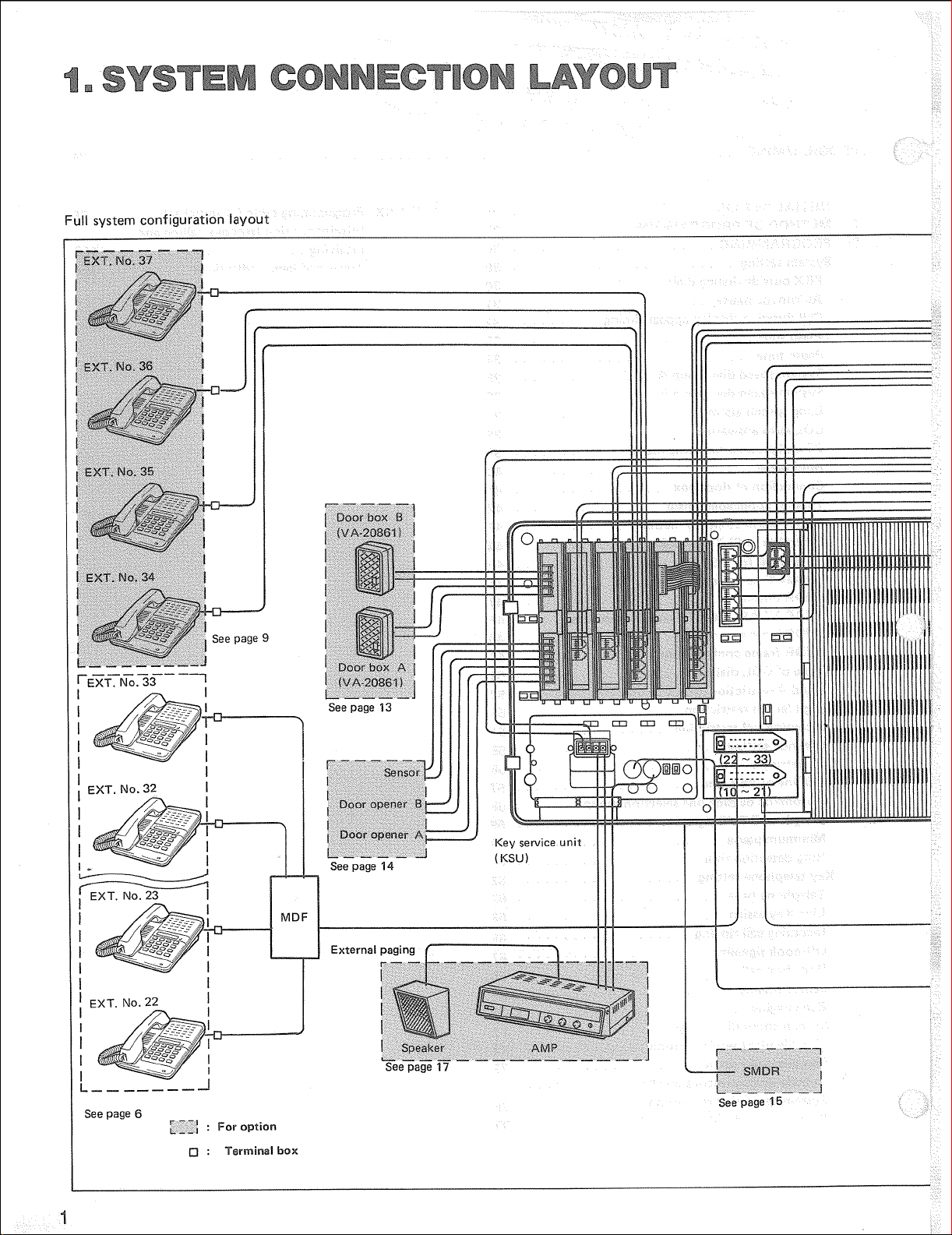
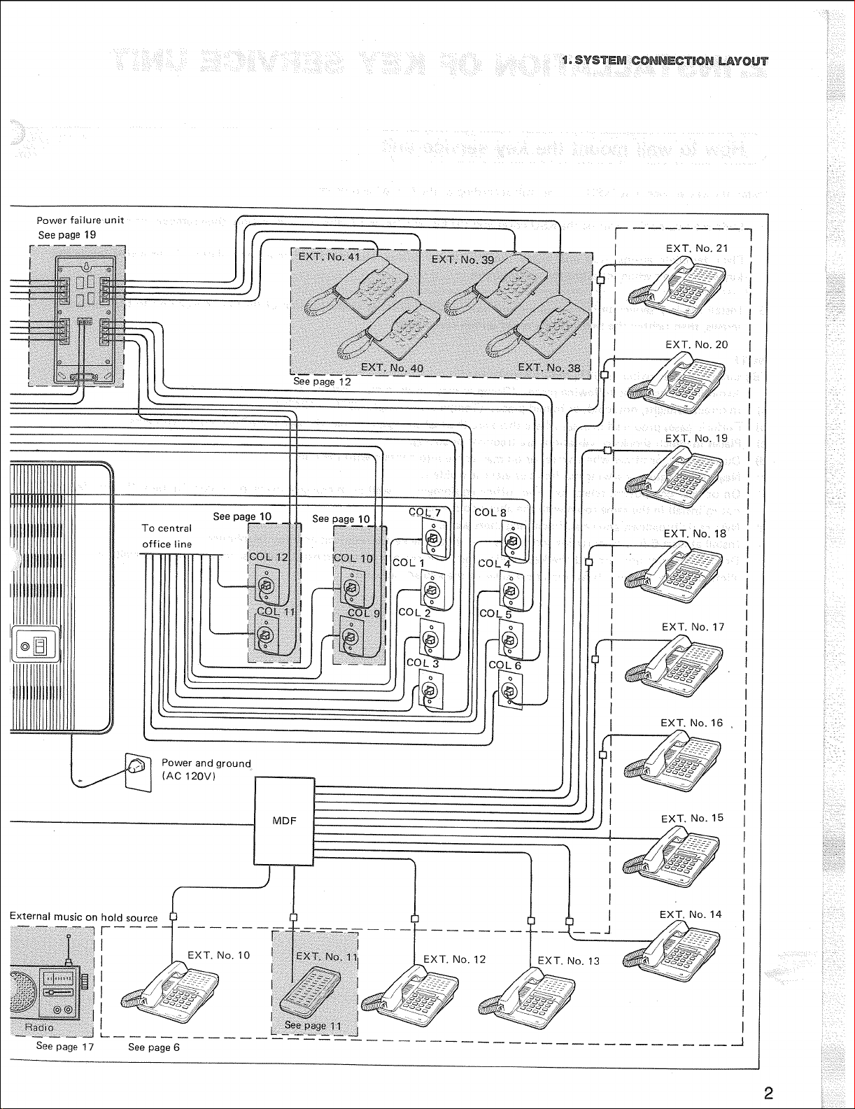
Thank you for purchasing the Panasonic Easa-Phone VA-1232, Key Telephone System.
This system can connect eight central office lines and twenty four key telephones and DSS, door box, external paging amp and
external music source can be added.
Please read this manual carefully before the installation of this system.
Please follow the installation procedure described below.
Before connecting telephone lines, inform to telephone company of the following.
COLl COL7
Telephone numbers
Model number
FCC registration number for VA-1232 KSU from factory ACK8GR-17656-KF-E
When modified to PBX (See page 18) ACK8GR-17655-MF-E
Factory interface code
Service order code
Ringer equivalence
Required network interface jack
COL2
COL3 COL9
COL4 COLIO
COL5 COLI 1
COL6 COL12
Panasonic VA-1 232
02 LS2
9.OF
0.48
USOC RJI IW, RJI IC
COL8
_
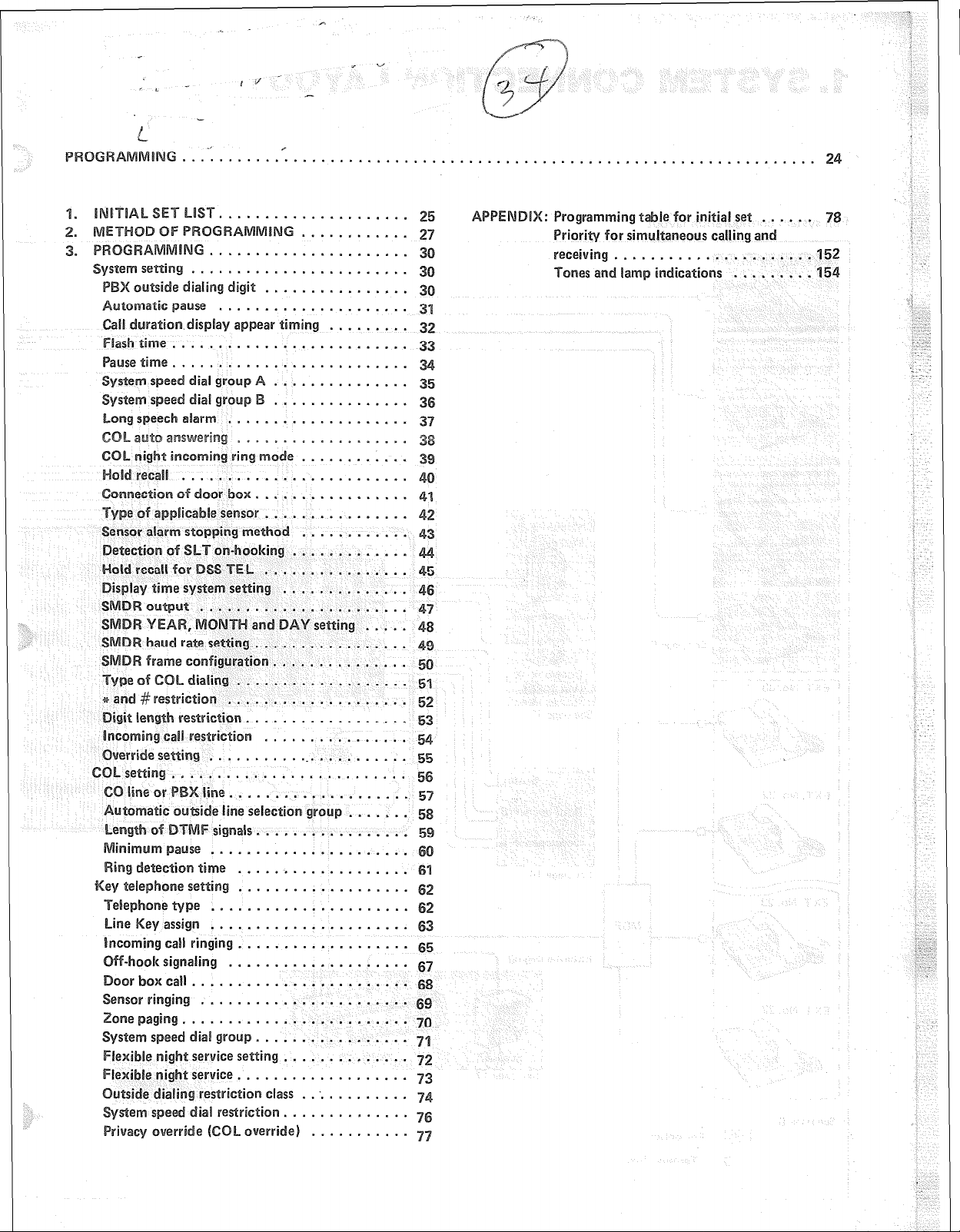
1. SYSTEMCONNECTIONLAYOUT ....................................................... 1
2. INSTALLATION OF KEY SERVICE UNIT
How to wall mount the key service unit
.................................................
...................................................
3. INSTALLATIONOFKEYTELEPHONE.. .................................................
How to wall mount the key telephone ....................................................
4. WIRINGCONNECTIONS .............................................................
Connection between the KSU, Key TEL and CO/PBX line ....................................... 8
Typeofwires ..................................................................... 7
Wiringcables..
...................................................................
5. CONNECTION OF OPTIONAL UNlT .....................................................
Variation of card connection
.......................................................... 9
Extension of CO/PBX line ............................................................ 10
Connection of direct station selector ..................................................... 11
Connections of single line telephone or -2 Key TELs/2 SLTs ...................................... 12
Connection of door box.
Connections of sensor and door opener.
ConnectionofSMDR ...............................................................
External music on hold source and external paging system
Set up for key service unit
8. CONNECTION OF POWER FAILURE UNIT
7. SPECIFICATIONS OF SYSTEM
Modules and system configuration
System capacity and specifications
Check list of parts.
.............................................................
...................................................
.......................................
............................................................ 18
................................................ 19
......................................................... 21
....................................................... 21
.......................................................
.................................................................
13
14
15
17
22
23
3
3
5
5
8
8
9
Page 3
.....................................
........................
.........................
ing .............
Ut .......................
.............
............
...............
..............
le for initial set ...... 7
Priority
152
ications ......... 154
setting
.................
~~~u~a~i~~ ...............
ialing ...................
....................
tion ..................
ing .......................
.......................
line.. ..................
e line s@i~~~i~~ .......
s~~~a~§. ................
se ......................
......................
assign ......................
call
ringing
~ig~a~i~g
rbQXCall.. ......................
~~~gi~~ .......................
aging .........................
t service setting
tservice
...................
.................... 67
...................
res~~~~~io~ class
.............. 7
7
.............
Page 4
Page 5
Page 6
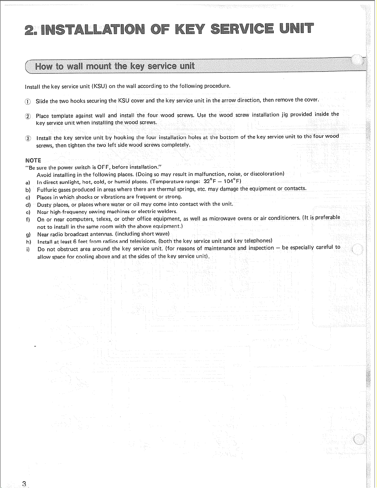
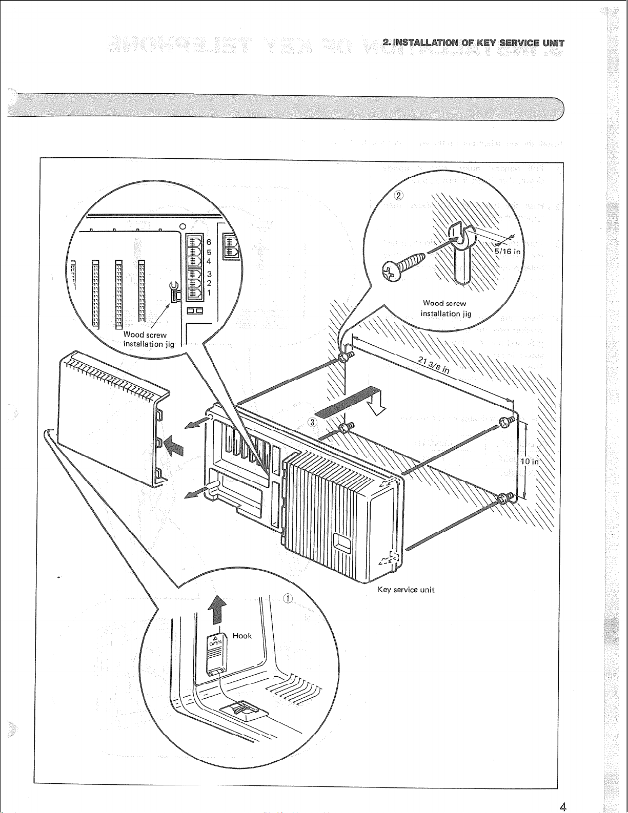
Install the key service unit (KSU) on the wall according to the following procedure.
@ Slide the two hooks securing the KSU cover and the key service unit in the arrow direction, then remove the cover.
@ Place template against wall and install the four wood screws. Use the wood screw installation jig provided inside the
key service unit when installing the wood screws.
‘Z.
@ Install the key service unit by hooking the four installation holes at the bottom of the key service unit to the four wood
screws, then tighten the two left side wood screws completely.
“Be
sure
the power switch is OFF, before installation.”
Avoid installing in the following places. (Doing so may result in malfunction, noise, or discoloration)
a) In direct sunlight, hot, cold, or humid places. (Temperature range: 32’F - ‘l04’F)
b) Fulfuric gases produced in areas where there are thermal springs, etc. may damage the equipment or contacts.
c) Places in which shocks or vibrations are frequent or strong.
d) Dusty places, or places where water or oil may come into contact with the unit.
e) Near high-frequency sewing machines or electric welders.
f) On or near computers, telexs, or other office equipment, as well as microwave ovens or air conditioners. (It is preferable
not to install in the same room with the above equipment.)
g) Near radio broadcast antennas. (including short wave)
h) Install at least 6 feet from radios and televisions. (both the key service unit and
Do not obstruct area around the
i)
allow space for cooling above
key
service unit. (for reasons of maintenance and inspection - be especially careful to
and at
the sides of the key service unit).
key
telephones)
‘,ii
;.
Page 7
Page 8

Install the key telephone on the wall according to the following procedure.
@ Pull handset guide, turn it upside
down, then insert it into its position.
@ Push the hooks at two places, then
remove the adapter.
@ Turn the adapter upside down, insert
the guides into two adapter mounting
holes provided at the lower portion of
the key telephone, then push in the
adapter.
@ Place the mounting holes of the
bracket over the studs of the modular
jack and pull the phone downward to
secure in place.
Short station cords are provided to
attach the key telephone.
Handset cord obtainable on the market.
VAX-20884 7 feet
VAX-20885 15 feet
Page 9

Make connections between the KSU, Key TEL and the central office/PBX line (CO/PBX) according to the following procedure.
Connect COL No. 1 through No. 8
jacks provided inside the KSU to the
CO/PBX line, respectively.
onnect EXT No. IO through No. 33
is desirable to use an LCD
display type key telephone (VA-1 2022
43) that is used for the
ING purpose described
later. (see page 28.)
a Push in the cables from the top of
the cable guide.
c$ Remove the clamp plate, insert
the cords, then reinstall the clamp
plate over the cords and secure
into place with the screw.
Keep the loop wire resistance to the
key telephone furthest from the key
service unit less than 40 ohms. (Max.
1100 feet with 22 AWG cable)
Do not wire the telephone cabls in
parallel with the AC power source,
s
computer, telex etc. If the cables run
near those wires, shield the cables
within metal tubing or use shielded
cable and ground the shields.
When cables run on the floor, use protectors or the like to protect the wires
where they may be stepped on. Avoid
wiring under carpets.
When using an AC power supply (AC
12OV), make sure the unit is ground.
To key telephone
Page 10
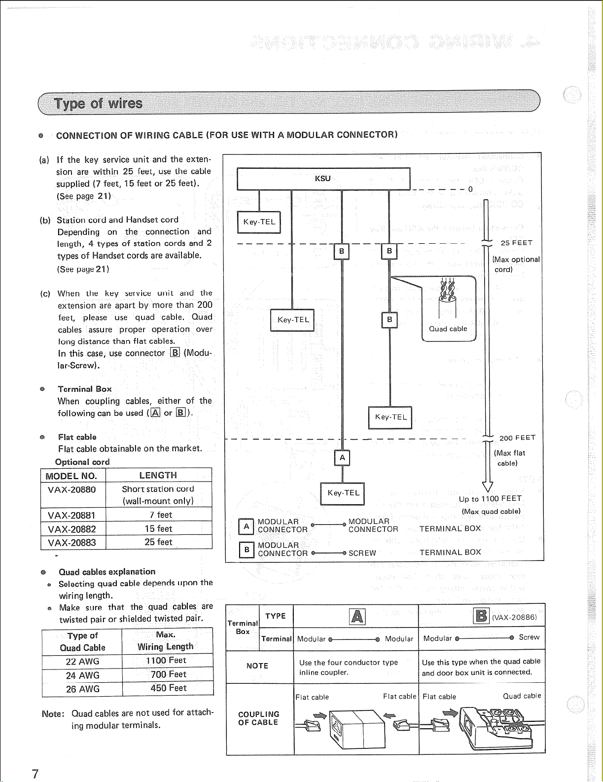
(a) If the key service unit and the exten-
sion are within 25 feet, use the cable
supplied (7 feet, 15 feet or 25 feet).
(See page 21)
(b) Station cord and Handset cord
Depending on the connection and
length, 4 types of station cords and 2
types of Mandset cords are available.
(See page 21)
(c) When the key service unit and the
extension are apart by more than 200
feet, please use quad cable. Quad
cables assure proper operation over
long distance than flat cables.
In this case, use connector
lar-screw).
ing cables, either of the
following can be used (
Flat cable obtainable on the market.
(Modu-
I
KSU
I
__-----
r
L
25 FEET
Max option<
cord)
200 FEET
IT
(Max flat
cable)
1
les ex~~a~at~~~
rng quad cable depends upon the
wiring length.
Make sure that the quad cables are
twisted pair or shielded twisted pair.
ate: Quad cables are not used for attach-
ing modular terminals.
MODULAR
CONNECTOR
MODULAR
CONNECTOR SCREW
lTerminall Modular Modular 1 Modular
OTE
COUPLlNG
OF CABLE
Use the four conductor type
inline coupler. and door box unit is connected.
Flat cable Flat cable Flat cable
MODULAR
CONNECTOR
up to 1100 FEET
(Max quad cable)
TERMINAL BOX
TERMINAL BOX
Screw
Use this type when the quad cable
Quad cable
Page 11

B:
R:
G:
YELLOW------J
Y:
Outer pins
Inner pins
Connect the cables to the modular connector and modular screw terminal so that the wires Y, G, R and B at both ends of the
cable are parallel.
Note that there are no polarity indications (plus or minus) for outer pins B and Y and inner pins R and G.
Connection of modular connector and modular-screw terminal.
ion to modular-screw terminal at both ends.
Modular-screw terminal Modular-screw terminal
L
For the outdoor wiring to prevent lightning hazard, connect the lightning protectors with TEL and KSU in such a
way that the distance between them can be kept short as
possible.
If telephone conversation is interrupted by lightning turn
off the POWER switch of KSU and turn it on again to see if
it works.
For
Key
TEL
v
G
R
I3
I I
---
GND
Circuit Diagram
KSU
-----
-----
-----
_----
I
I
ZNR = ERZCIOK 391
-: -.- -
I I.
G
R
I3
GkD
Page 12

If you are not using key telephones other than those initially mounted, door boxes or external paging, you can disregard this
section.
For installing more telephones, three variations are available to connect station card as shown below. Extention Nos. are
indicated on each card depending on jacks.
of VA-30940D, 30941 D and 309420 when you use Ihe VA-1 232 system (except
VA-30940D VA-30941 D VA-30942D
‘B
Key TEL 32 pcs Key TEL 30 pcs Key TEL 28 PCS
SL-r 0 SLT
2 pcs SLT
4 pcs
DPH COLl LC2 Lcl LC2 LC-S
(4KT) (4KT)
WI
Station card I
(VA-30940D)
DPH COLI LC2 LCl LC2 LC-S DPH COLI COL2 LCI LC2 LC-S
(4KT) (2KT) (2SLT)
-4 -_i
Station Station Station Station
card I card El card I card ll
(VA3094OD) (VA30942D)
(41(T) W3-S’)
--J i___-
(VA30940D) WA30941 D
’ :-.
Page 13

Be sure the power switch is off, before installing or removing the cards.
Make connections of an CO/PBX line cards and to respective CO/PBX line according to the following procedure. When inserting the CO/PBX line cards, make sure that the card top and bottom ribs are aligned with the respective slots located at the
regular positions inside the key service unit.
line cards
Insert the CO/PBX line cards into the
key service unit. This one card makes
four CO/PBX lines operable.
Co~~~~~io~ of central office lines
COL12
COLll
COL 10
COL9
Connect the central office lines to the
respective jacks on the card. COL
Nos. 9, 10, 12 and 12 assigned to the
connectors in order from the top.
Page 14
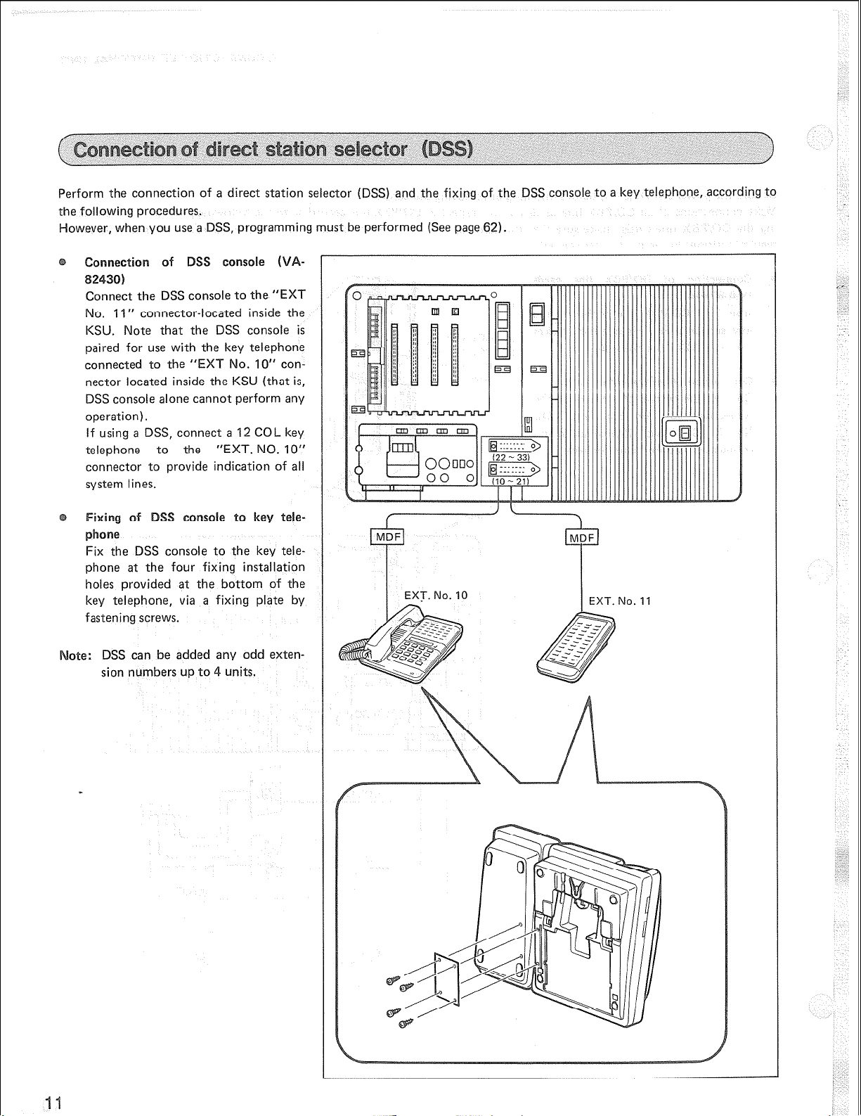
Perform the connection of a direct station selector (DSS) and the fixing of the DSS console to a key telephone, according to
the following procedures.
However, when you use a DSS, programming must be performed (See page 62).
Connectio of DSS console (V
82430)
Connect the DSS console to the “EXT
No. 11” connector-located inside the
KSU. Note that the DSS console is
paired for use with the key telephone
connected to the “EXT No. 10” con-
nector located inside the KSU (that is,
DSS console alone cannot perform any
operation).
If using a DSS, connect a 12 COL key
telephone to the “EXT. NO. IO”
connector to provide indication of all
system lines.
ixing of SS console to key tele-
phone
Fix the DSS console to the key telephone at the four fixing installation
holes provided at the bottom of the
key telephone, via a fixing plate by
fastening screws.
ate: DSS can be added any odd exten-
sion numbers up to 4 units.
Page 15

Make connections according to the following single line telephone connecting method and the 2 Key TEL/2 SLT connecting
method. When inserting a card, make sure that the card top and bottom ribs are aligned with the respective slots located at
the regular positions inside the key service unit. Programming is required for connecting a single line telephone
) Connection of station card II
(I
(See page 62).
(VA-30941 D)
Insert the station card II into the key
service unit, and insert the other piece
into its slots to the right of the first
EXT. No. 41
EXT. No. 40
EXT. No. 39
EXT. No. 38
card. One card is capable of making
4 single line telephones usable.
(2) Connection of single line telephone
Connect each of single line telephones
(Station card II )
to the respective jacks located on the
right side card. The jacks are allotted,
in order from the top, extensions
No. 41 through No. 38 respectively.
(1
) Connection of Station card III
(VA-30942D)
Insert the station card III into the key
service unit (for key TEL) and insert
the other piece (for SLT) into its slots.
One card is capable of making 2 key
telephones and 2 single line telephones
usable.
(2) Connection of Key TEL/SLT
Connect each of key telephones to the
respective jacks located on the key
T-EL card. Then, connect each of
single line telephones to the respective
jacks located on the station card II.
The jacks on the key TEL card are
allotted, in order from the top, exten-
sions No. 39 and No. 38, while those
on the SLT card are allotted, in order
from the top, extensions No. 41 and
No. 40.
EXT. No. 38
EXT. No. 41
EXT. No. 39
Page 16

Make connections of a door box card and of door box according to the following procedure.
Insert a door box card into the key
service unit. This one card is capable
of making 2 door boxes usable.
Door box
Door box
This card may be used for sensor and
door openers. (See page 14)
and to the
screw terminals (2 terminals make a
pair) located on the door box card.
Rib
b------- 3$in----4
Door box A
(VA-20861)
Door box B
(VA-20861)
,
. -:
‘\
Page 17

Make connections of sensor and door opener according to the following procedures.
(1) Insert a door box card (VA-30960)
into the key service unit.
This card makes sensor usable and also
be used for door box. (See page 13)
(2) Connect the sensor terminals (screw
terminals) on the door box card to
sensor to be used and must meet the
following requirements for connection.
II
Requirements for connection
(a) Always use a relay-type sensor.
(b) Ratings for contacts
See figure
(I) Insert a door box card (VA-30960)
into the key service unit. This one
card makes two door openers usable.
Contact with-stand voltage
: MIN. 5 V
Contact current
Contact resistance : MAX. 0.1 s2
: MIN. 2 mA
(2) Connect the screw terminals (two
terminals make a pair) located on the
door box card to the respective
door openers. Since the door openers
are one-to-one corresponding to the
door box, connections should be made
as shown below.
Door box of Door opener
Door box * Door opener
s
Note that the door openers to be used
must meet the following requirements
for connection.
Requirements for connection (Requirement for driving contacts of the
relay installed in KSU)
See figure
Door opener B
Drive voltage
:MAXAC50VorMAXDC30V
Drive current
: MAX 1 A
Operation time
: Approximately 1 second
Door opener A
L
Page 18

This system enables the output from KSU call record data for a telephone (duration of call, etc.) through the RS232C interface.
These data are output by the printer connected to KSU.
Programming is necessary for outputting from KSU. (See page 47)
connector of KSU and the printer (KXP1080i) by means of the RS232C cable. Note that because
the printer (KX-Pl080i) uses a parallel interface, KX-Pl1D is also necessary. See the manual for the RS232C interface
board (KX-PI 1 D) for how to mount KX-PI 1 D to the inside of the printers.
ecOr a
The following is an explanation concerning the output format and display contents for call record data.
am at
(Call record data with title)
UXXLJXX
G T$
TIME DURAT. C COf
uuuuxx:xxux:xx.xuxuuuxuuuuuxxxxx-xxx-xxxxuuuxxuuuuxxxxx
(Call record data only)
DIALED NO. TEL:: ACCTL’
U : Blank x : Data
D: When call has lasted over 10 hours.
L : For conference call.
I : For incoming call
Blank: For outgoing call.
t to a maximum
Page 19

CB
I
jti 1
7
1 CTS 1 20 *
7
I SG I AB
,
20
[ DTR 1
I
CD
Page 20

Make connections of the external music on hold ( OH) source and of the external paging system according to the following
procedure.
(I) Set the “MOH” switch inside the key
service unit to the “EXT” side.
(2) Connect from earphone or aux. out
jack to RCA “Mot-(” jack inside the
key service unit.
Do not connect directly to speaker
edanee 5
I&, level max. -10 dB)
) Connect an external amplifier to the
(I
“EPA-OUT” jack and to the “EPA-C”
terminals inside the key service unit.
The “EPA-C” terminals are to control
turning ON/OFF of the external
amplifier power.
Use RCA-type jack (output impedance: 600 Q, level: 0 dB) for the
connection to the “EPA-OUT” jack.
(2) Connect the external paging speaker
to the amplifier.
The functions of “EPA VOLs 1 and 2’
located inside the key service unit are
as follows.
EPA VOLI :
_ This volume is to control the level
of the music output applied from the
external sound source to EPA jack.
EPA VOL2:
This volume is to control the level of
the voice output applied from the TEL
to paged TEL, and EPA jack output.
,
EPA-VOL I volume
Radio
Speaker
Page 21

The internal set uP of the KSU and the explanations of switches and lamps are provided below.
(1) MOH Switch
Perform the set up of the MOH switch.
INl- :
EXT : To use external music on
(1) Power Switch
This AC power switch is to control
the whole system.
(2) Power Monitor Lamp
This lamps is to indicate that the
output level from power supply unit
is normal.
(3) RESET Switch
This switch resets the sYstem.
If the RAM switch is set to “HOLD”
system programming and speed dials
will not be reset.
To reset the system,short the two sides
of the pattern by inserting a screwdriver or other conductive implement.
To use built-in hold tone.
hold source. (See page
17.)
For PBX set jumper
r
(4) RAM Switch
This switch backup the RAM data.
Even when the power failure occurs,
the RAM memory data will not be
erased if the switch is on HOLD side.
(5) PATA MONIT Lamp
System is normal when lamp is flash-
i ng.
rogramming
line selection group.
In the FCC rules, this function is
regarded as one of the distinguishing
features of PBX as against the Key
telephone system. When shipped from
the factory this function cannot be
programmed unless one jumper on the
key service unit board is cut. (See page 5t
for automatic outside
Power Monitor Lamp
DATA MONIT Lamp
RESET switch
Page 22

Power Failure Unit (PFU) is optional equipment which, in case of power failure, directly connects CO/PBX lines and Single
Line Telephones.
all ~~~~~~~~ merho
@ Remove a PFU cover.
@ Install one wood screw on the wall remaining about 5/16 inches of the screw length unscrewed.
@ Hook the mounting hole provided at the top of the PFU to the on-wall installed wood screw, then fasten the wood screw
completely.
@ Install two wood screws on the wall through the two respective mounting holes provided at the bottom of the PFU.
(1) Connect the connectors labelled “FROM COL” (COL ‘I to 4) and located inside the power failure unit to the respective
central office lines.
(2) Connect COL NOS. 1, 2, 3 and 4 inside the key service unit to the connectors (4 places from the top) labelled “TO COL
(KSU)” and located inside the power failure unit, respectively.
I
(3) Connect the connectors (4 places from the top) located on the card of the SLT card (right side card), vvhich is set inside
the key service unit, to the connectors labelled “FROM SLT-LC(KSU)” and located inside the power failure unit, respectively.
(4) Connect the connectors (TELs 1 to 4) labelled “TO SLT” and located inside the power failure unit to the respective single
line telephones. These connectors are allotted, in order from the top, Extensions Nos. 38,39,40 and 41.
(5) Connect the two screw terminals labelled “PFU” and located inside the key service unit to the respective two screw
terminals labelled “TO KSU” and located inside the power failure unit.
(6) Remove the clamp plate, insert the cords, then reinstall the clamp plate over the cords and secure into place with the
screw.
Note: That when power failure occurs the COLs correspond to iXTs as shown below.
COL 1-+ EXT. No. 38
COL 2 -+ EXT. No. 39
COL 3 -+ EXT. No. 49
COL 4 -+ EXT. No. 41
Page 23

I16 in
from
SLT card
of KSU
EXT. No. 38
EXT. No. 39
EXT. No. 40
EXT. No. 41
r
-EXT. No. 39
-EXT. No. 40
-EXT. No. 41
COL 1
p; toCOL
COL 4
I
to KSU
to SLT
Page 24

tion
VA-123210 I<ey service unit 1
VA-30920 Standard telephone
VA-1 2020
VA-1 2022
VA-12022-6 1 Speakerphone with LCD Display
VA-82430 DSS console
VA-82444
VA-3094OD Station card I 2
VA-30941 D
VA-30965 Power failure unit 1 1
VAX-20880 Short station cord for wall mount
VAX-20881 Telephone line cord (7 feet)
VAX-20882
VAX-20883 Telephone line cord (25 feet)
VAX-20884 I f-fandset cord (7 feet)
VAX-20885
Standard telephone
I
Speakerphone
Speakerphone with LCD Display
I
I I
I
I
I
COPBX line card
I I
Station card
I I
Telephone line cord (15 feet) -
1 Handset cord (15 feet)
II 1
I I -
I -
5 I:::l~orn hands free i
32
~~1
4
2
IO
pi
13
IQ 1 pee for 4 COLs
-
-
Forl2COLs and 32 key telephones
VA-12022 in Black Color Type
I
Ipce. for 2 COIPBX line
t
9 1 pee for 4 key telephones
1 pee for 4 single line telephones
-
-
-
-
75 University Avenue, Westwood, Messachusetts 02090
5 Pine West Plaza, Washington Avenue Extension, Albany, New York 12205
50 Wleadowlands Parkway, Secaucus, New Jersey 07094
3rd Place, Suite F, Aurora, Colorado 8001
ne Gateway Center 426 North 44th, Suite
Page 25

COL capacity
12
intercom speech path
Key telephone*
Automatic dial
One touch dial
System speed dial
Speed dialing digits
edialing digits
(i
Key Service Unit
Key Telephone
Power Consumption (Watt)
6
UP to 32 (EXT. No. 10 to 41)
10 stations (for each telephone)
90 stations (for the system)
18 digits/Station (included PBX access code)
18 digits/Last number and save number
1 an eight (
12.8(H) x 23.0(W) x42(D), 9.5(ib)
8.5( l-4) x 6.7(W) x 2.4(D), 2.2(lb)
H
: ‘1, Specifications subject to change without notice.
2. &IV of the below combination
a. 32 Key telephones
b. 30 Key telephones 2 single line telephones
c. 28 Key telephones (k 4 single line telephones
Page 26

When you unpack the system phone, make sure that you have all of the following parts.
@Y
Key Service Unit (VA-123210)
Short station cord for wall mount
Operating instruction assy
Installation and programming manual assy
Base 1 pee
Handset
ice nit
Operating instructions
Operating instructions sheet
Installation and programming manual
Programming table
Screw template for wall mounting KSU
1 pee
3 pcs
1 set
1 copy
20 copies
1 set
1 copy
1 COPY
1 COPY
1 pee
Handset cord
Station cord
Name card of system speed dial 1 set
Name card of individual speed dial
Plastic case for system speed dial
1 cpe
1 pee
1 COPY
1 pee
Page 27

The Easa-Phone VA-1232 is a small, sophisticated Key Telephone system. It offers many features which can be easily programmed to uniquelly fit your communication needs.
The Easa-Phone utilizes Random Access Memory (RAM) for storage of the “User’s” variable programs and features. Each
telephone station can be assigned a set of features based on the individual “User’s” requirements.
Note that a program has been preset into the Easa-Phone VA-1232 system memory for
Set. Thus, no programming is necessary to immediately use your telephone system. Wowever, to properly change from the
Initial Set to any other option, the programming steps detailed under the Programming Settings for the desired feature must be followed. A programming record chart is provided for ease of recording yo indicating the Initial Set can be found in the back of this manual. henever programming changes are made, they should be immediately recorded on the Programming Table to provide a quick reference of the current programmed feature options.
s
program changes. A sample of this Programming Table
general
use which js called the Initial
.~....~.............~...~................,...........~......~..... 5
..~..~..*..*...~..*.~~...*..,...*~.~.,.~..~.~*......*.... 27
. . . ..~~.............*...*......*........~....*..*.*.~~..**.........
. . . ..~.~.~......~.~.........~..~.....~.~...~~~...~.~.......~~~...~.~.~.~..
Page 28

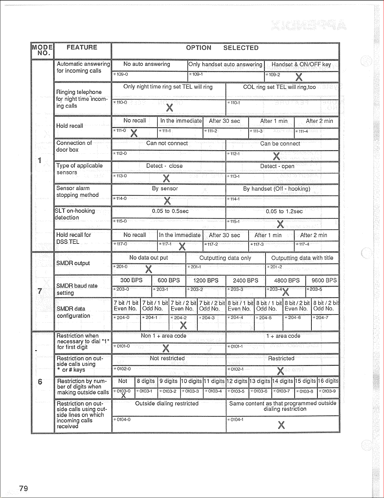
The table below describes the features, initial setting and those programming mode.
ause time I 2 set I 3 set
Recall after 30 set, 1 min, 2 min or immediately
--
30
31
32
33
34
35
36
37
36
39
40
41
42
ispley time system se
frame configuration
restriction ot restricte Restrict one of the digit
ecall after 30 set,
7 bit/l billeven, 7 bit/l bit/odd, 7 bit/2
bit/odd, 8 bit/l bit/even, 8 bit/l biVodd,
8 bit/2 bit/even, or 8 biV2 bit/odd
1 rrvn,
lenoth from
8 to 16 diaits
43
44
45
46
47
48
49
50
51
52
53
54
55
Page 29

. IO rings calls of
A will ring or only B will ring
no.10 is used always as
O/l & 4114555~976 restricted
Page 30
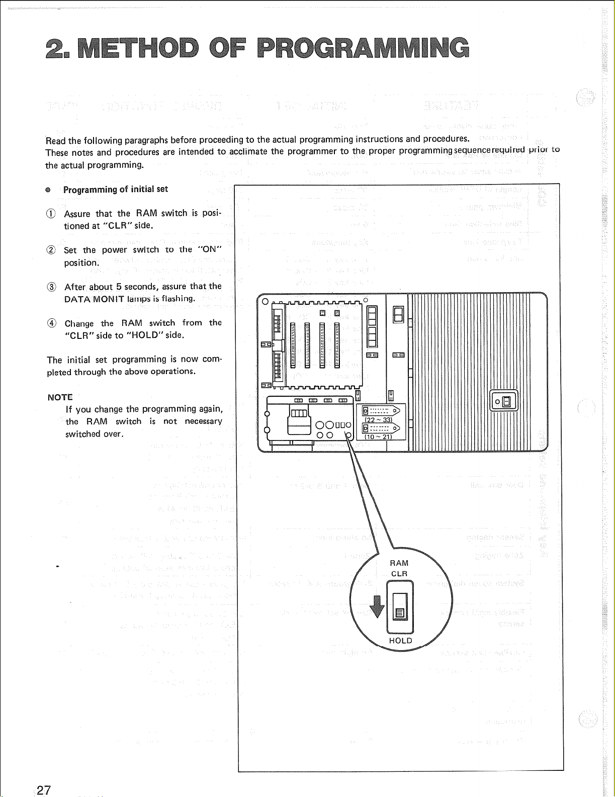
‘Read the following paragraphs before proceeding to the actual programming instructions and procedures.
These notes and procedures are intended to acclimate the programmer to the proper programmingsequencerequired prior to
the actual programming.
programming of initial set
@ Assure that the RAM switch is posi-
tioned at “CLR” side.
@ Set the power switch to the “ON”
position.
@ After about 5 seconds, assure that the
DATA MONIT lamps is flashing.
@ Change the RAM switch from the
“CLR” side to “HOLD” side.
The initial set programming is now completed through the above operations.
If you change the programming again,
the RAM switch is not necessary
switched over.
27
Page 31

All programming changes are made at
Extension No. 10 and it is recommended to use key telephone with a LCD
display (VA-1 2022 or VA-12022-B).
@ Press the ON/OFF button. The ON/
OFF indicator and MIC indicator
lights up and a continuous tone is
emitted.
mode 1:
System setting
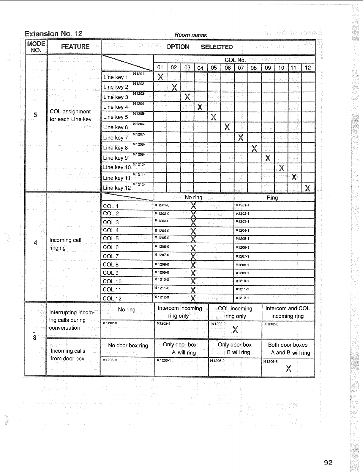
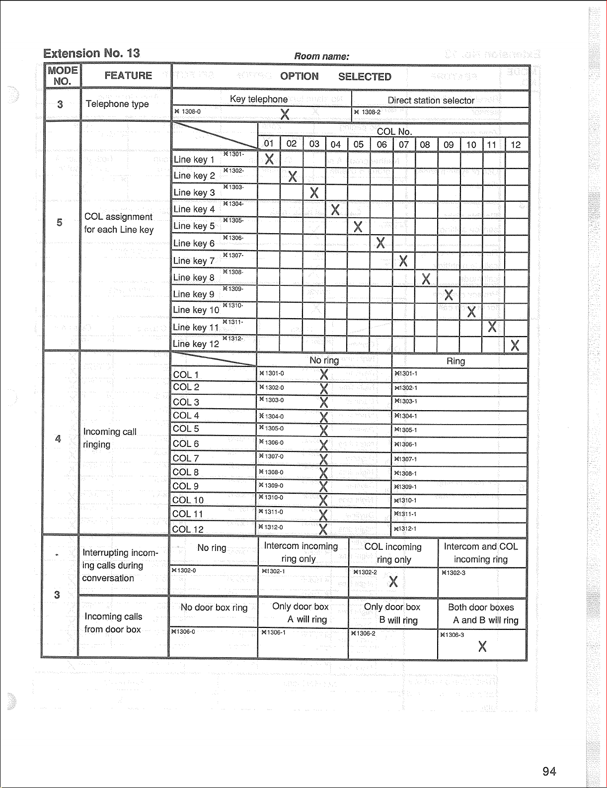
mode 2: COL setting
mode 3:
Key telephone setting
mode 4: Incoming call ringing setting
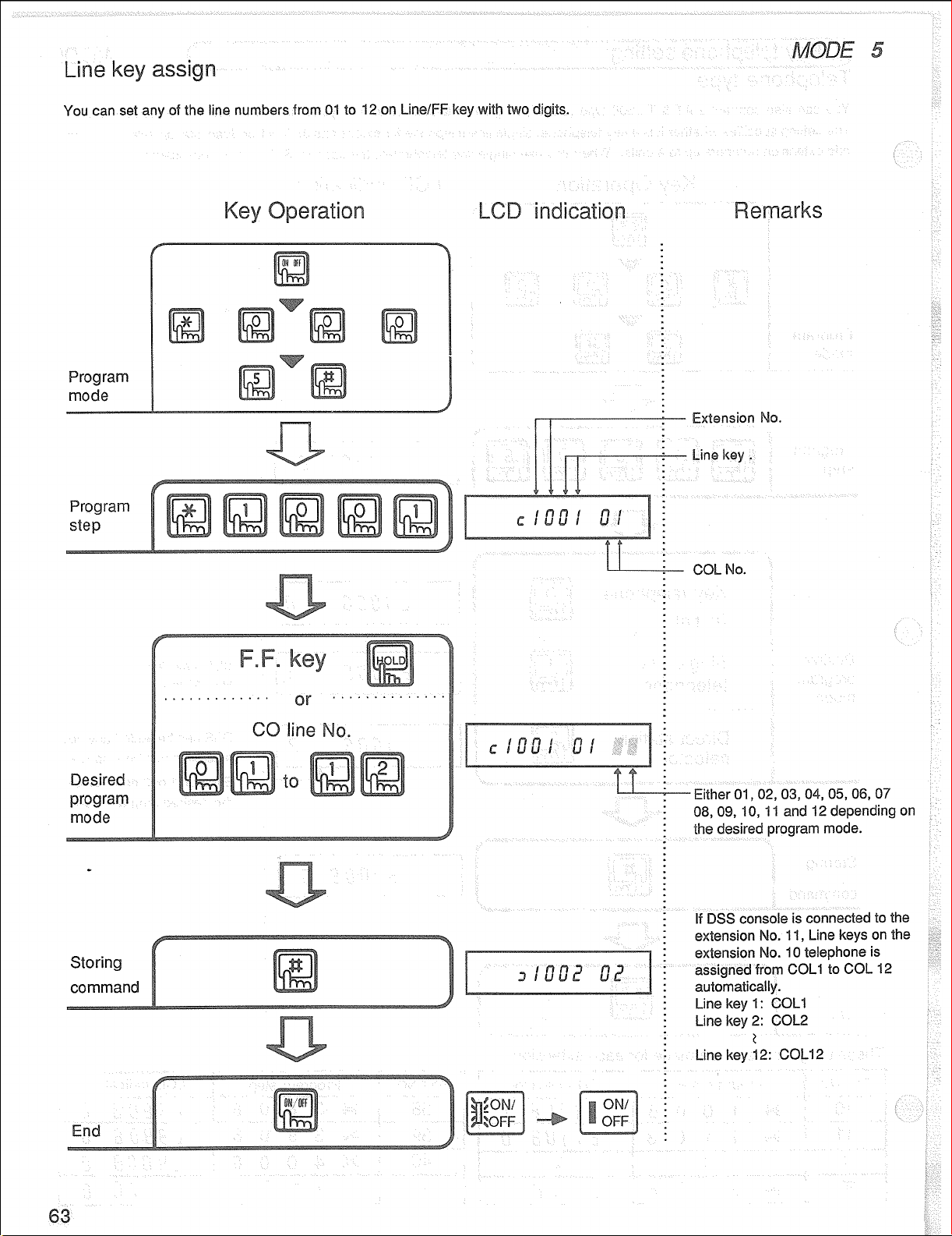
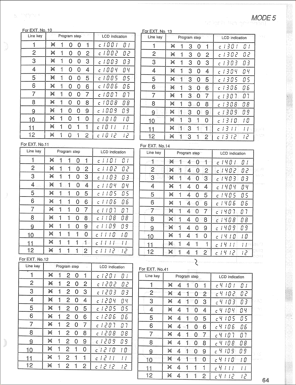
mode 5: Line/FF key setting
mode 6: Restriction setting
mode 7:
Display time setting
@ Press the program step numbers for
the desired feature option. Refer to
the PROGRAMMING TABLE for
programmable feature option.
@ Press the key to store the memo-
ry. The next program step will appear
on the LCD display. When mode
numbers of the programming features
to be changed are the same, program
step numbers of the programmings to
be changed can be input after the
registration. Therefore, the programm-
*
ing changes can be performed continuously for the programming features
having the same mode number.
LCD display
ON/OFF Button
ON/OF1 indicator
@ Press the ON/OFF button and display
will return to the clock mode (ON/
OFF indicator and MIC indicator will
go off).
If you want to confirm the mode number during programming, you can do
so with the LCD display by inputting
I, ,,
Page 32
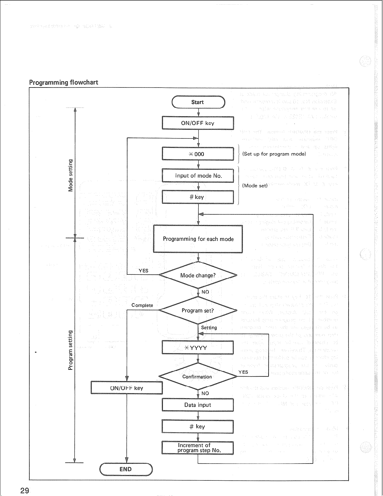
Programming for each mode
gram I
(Set up for program mode)
.
Page 33

You can have access to an outside line through PBX. This feature is necessary when the system is connected to PBX. Set
by sp@ccifying one digit from among dialing numbers 0 to 9 (PBX line access number ),
in at i
Program
mode
Program
step
Desired
program
mode
0 thru 9 can be programmed.
Initial setting is 9.
30
Page 34
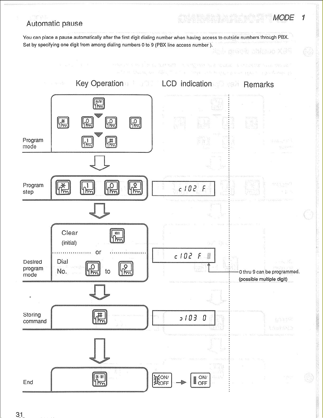
You can place a pause automatically after the first digit dialing number when having access to outside numbers through
Set by specifying one digit from among dialing numbers 0 to 9 (PM line access number ).
Program
e
Program
step
PBX.
Desired
program
mode
End
-0 thru 9 can be programmed.
(possible multiple digit)
Page 35

hen making an outside call by a key telephone with an LCD display, you can set how many seconds after completion of
dialing you want the conversation time to appear on the display.
Program
mode
Program
step
Desired
program
mode
Storing
command
(Initial)
fter 30
set
-Either 0 or 1 depending on the
desired program mode.
Page 36

You can set the length of open time for an outside line with FLASW key and that of auto-flash time with REDIAL key function.
hen you wish to use the call aiting service, just press FL
If the system is connected to the P X line and you do not use the hold function of PBX system, set to 2 seconds.
Program
mode
Program
step
Desired
program
mode
.6 set
1 set (Initial)
2 set
-Either
0,
1 or 2 depending on
the desired program mode.
Page 37

By
pressing
digit. This is used when YOU need to wait for a second dial tone when dialing an outside line.
REDlAL key, a pause can be
stored in
the system speed memory and one-touch key. One pause is counted as one
Program
e
Program
step
Desired
program
mode
L
2 set
(Initial)
3 set
L
Either 0 or 1 depending on the
desired program mode.
:
Page 38
sle
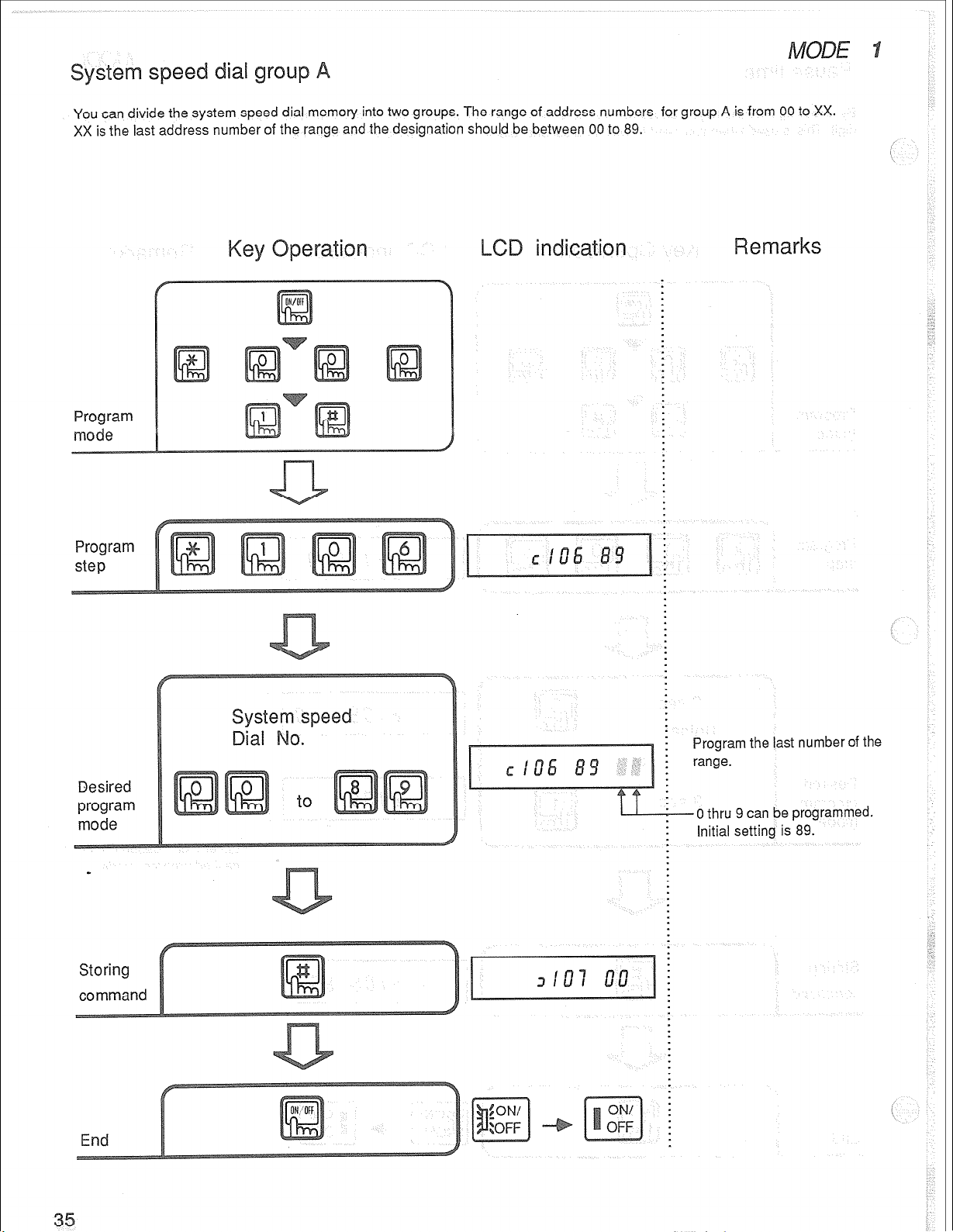
You can divide the system speed dial memory into two groups. The range of address numbers for group A is from 00 to XX.
XX is the last address number of the range and the designation should be between
Program
mode
00
to 89.
Program
step
Desired
program
mode
i Program the last number of the
: range.
0 thru 9 can be programmed.
Initial setting is 89.
Page 39

YOU
can
divide the system speed dial memory
the first address number of the range and the designation should be between
into two groups. The range of address numbers for group B is from YY to 89. YY is
00
and 89.
Program
Program
step
erali
in
at i
Desired
program
mode
End
Program the first number of the Program the first number of the
range. range.
0 thru 9 can be programmed. 0 thru 9 can be programmed.
Initial setting is 00. Initial setting is 00.
Page 40

hen making an outside call, you can set SO that a short alarm tone sounds from the speaker or handset every three minutes.
I,... in
Program
e
Program
step
Desired
program
mode
Storing
command
lawn tone
(Initial)
. . . . . . . . . . . . . . . . . . or
we alarm lone
I
Either 0 or 1 depending on the
: desired program mode.
Page 41

You can answer incoming calls without pressing Line key. There are two systems for answering: one is to
and the other is either to lift the handset or press ON/OFF key,
Program
m0de
Program
step
simply
lift the handset
Desired
program
mode
...........
.................. ...........
-Either 0, 1 or 2 depending on the
desired program mode.
Page 42

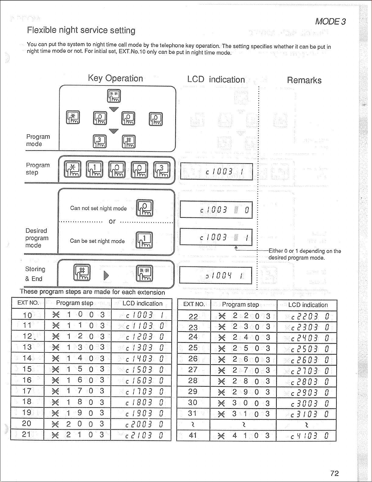
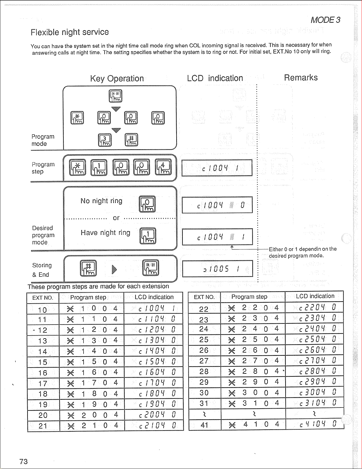
You can specify telephones to ring in case of night time incoming calls in systems programmed for this purpose . This is
necessary when the places for r ceiving incoming calls are different at daytime and night time.
Program
step
Desired
program
mode
Only night time ring
set TEL will ring.’
(Initial)
COL ring set TEL
will ring,too.
Either 0 or 1 depending on the
: desired rxoaram mode.
Page 43

Hold recall can
Program
aming tone sounds once ace&in period has elapsed after a calI has been put on hold.
disabled, or set for immediately, 30 seconds, 1 minute or 2 minutes.
Desired
program
mode
Storing
command
Either 0, 1, 2, 3 or 4 depending
on the desired program mode.
Page 44
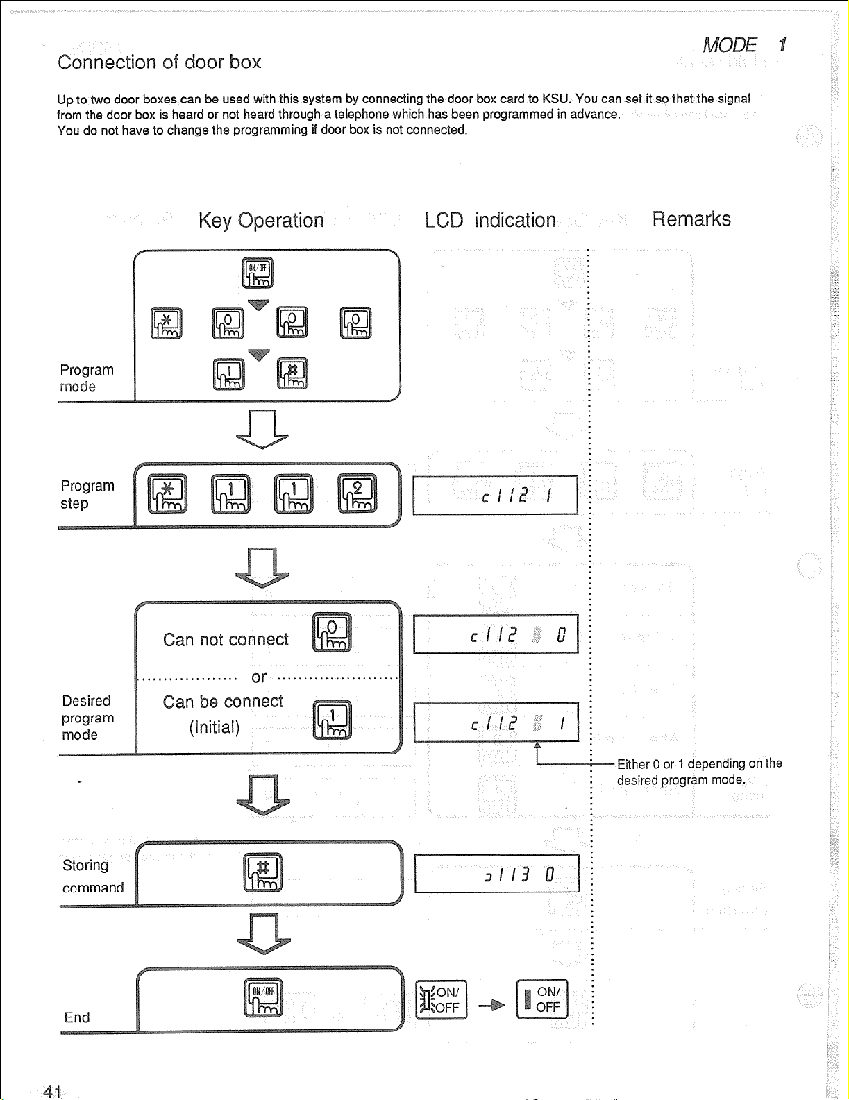
Up to two door boxes can be used with this system by corm
from the door box is heard or not heard through a telephone
You do not have to change the programming-if door box is not connected.
ng the door box card to KSU. You can set it so that the signal
ich has been programmed in advance.
Program
e
Program
step
-
Desired
program
mode
an n
,.*.. * . . . . . ..I.. *. or
nn
(hitial)
. . . ..**.**.**t......*.
Either 0 or 1 depending on the
desired program mode.
Page 45
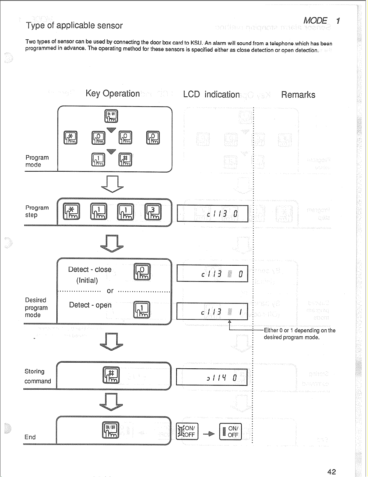
Two
lypss of sensor can bs used by connecling the door
programmed in advance. The operating method for these sensors is specified either as close detection or open detection.
Program
mode
Program
step
box card to KSU. An alarm will sound from a telephone which has been
Desired
program
mode
Storing
command
(Initial)
eteci - open
-Either 0 or 1 depending on the
desired program mod&.
Page 46
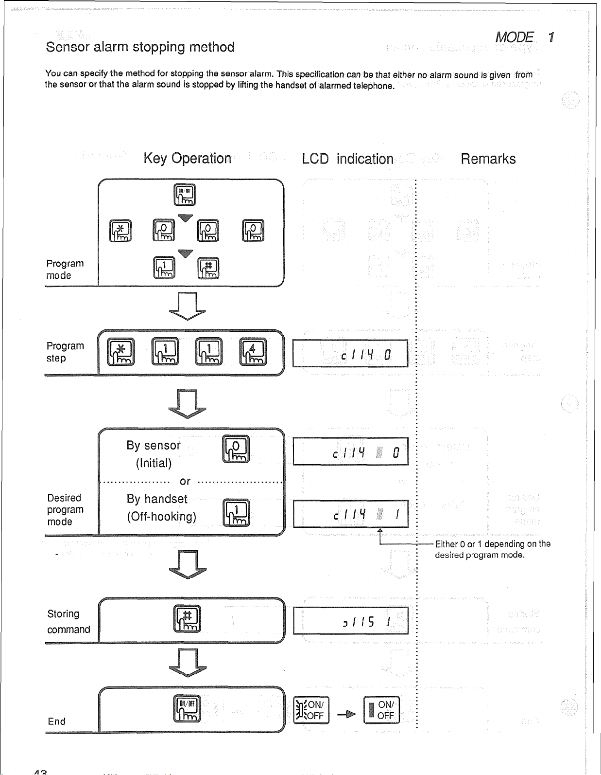
in eth
You can specify the method for stopping the sensor alarm. This specification can be that either no alarm sound is given from
the sensor or that the alarm sound is stopped by lifting the handset of alarmed telephone.
Program
ode
Program
step
Desired
program
mode
y SenSOr
(Initial)
. . . . . . . . . . . . . , . . . . or . . . . . . ..*.....*.*.*...
y handset
(Off-hooking)
1
Either 0 or 1 depending on the
: desired program mode.
Page 47
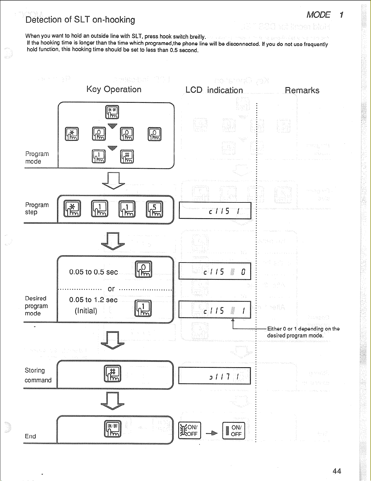
hen you want to hold an outside line with SLT, press hook switch breifly.
If the hooking time is longer than the time which programed,the phone line will be disconnected. If you do not use frequently
hold function, this hooking time should be set to less than
Progra
MO&?
Program
step
0.5
second.
Desired
program
mode
Storing
command
(Initial)
Either 0 or 1 depending on the
: desired program mode.
Page 48
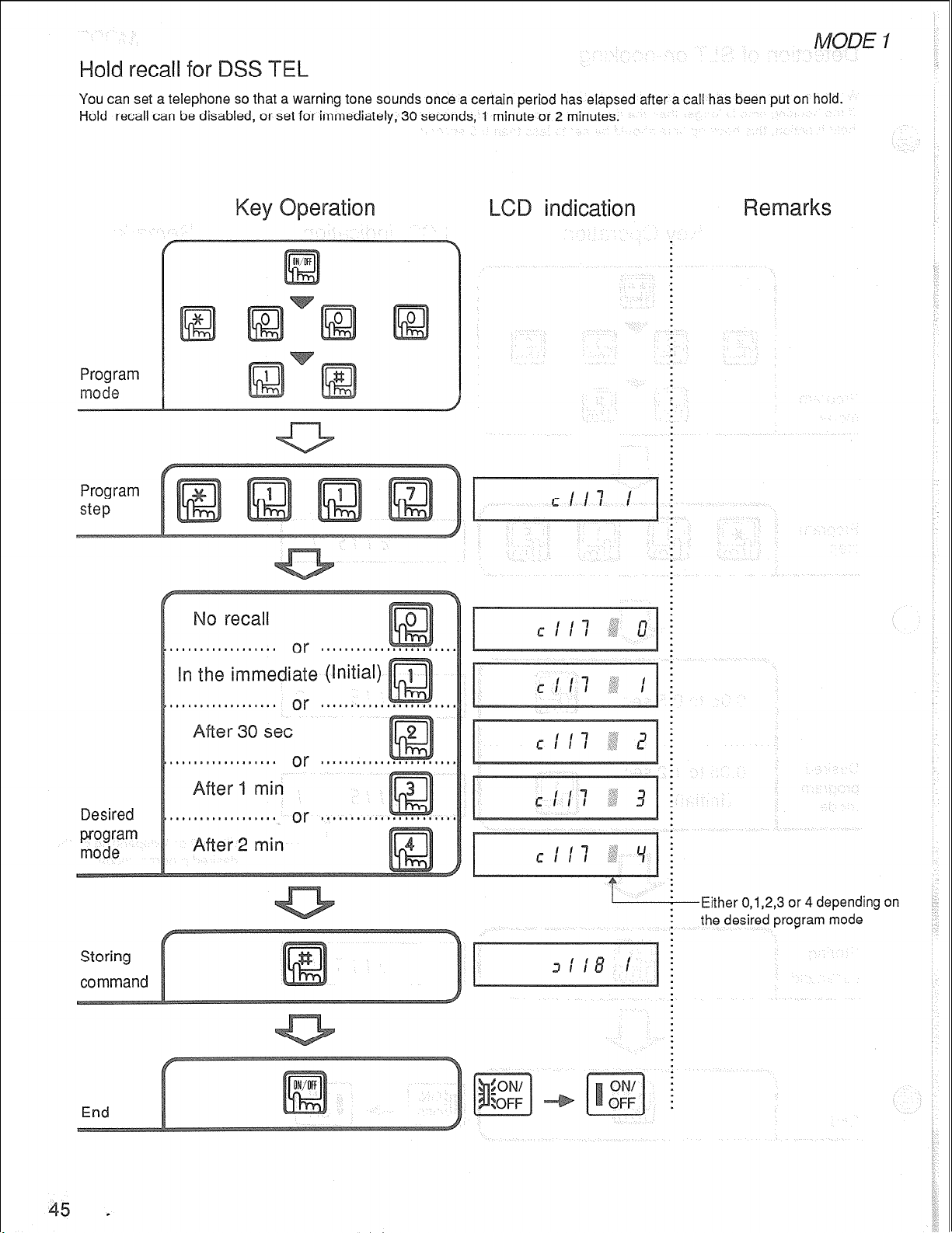
recall f
You can set a telephone so that a warning tone sounds once a certain period has elapsed after a call has been put on hold.
Hold recall can be disabled, or set for immediately, 30 seconds, 1 minute or 2 minutes.
Program
mode
Program
step
Desired
program
mode
5 .
: the desired program mode
Page 49

This feature is for setting the correct time for a key telephone with an
mode
Program
step
LCD display.
Desired
pro”gram
mode
A : 12:o
P : 12:o
is for night.
is for daytime.
Page 50

This feature is to program to output data onto the S
This is necessary when you want to notify the call record.
You can set for not outputting SMDR data, outputting the data with the title or outputting the data only.
Program
mode
Program
step
L.
n
Desired
program
mode
.................
.................
or ...... .......
Outputting da’r&
ith title
Either 0, 1 or 2 depending on the
desired program mode
Page 51

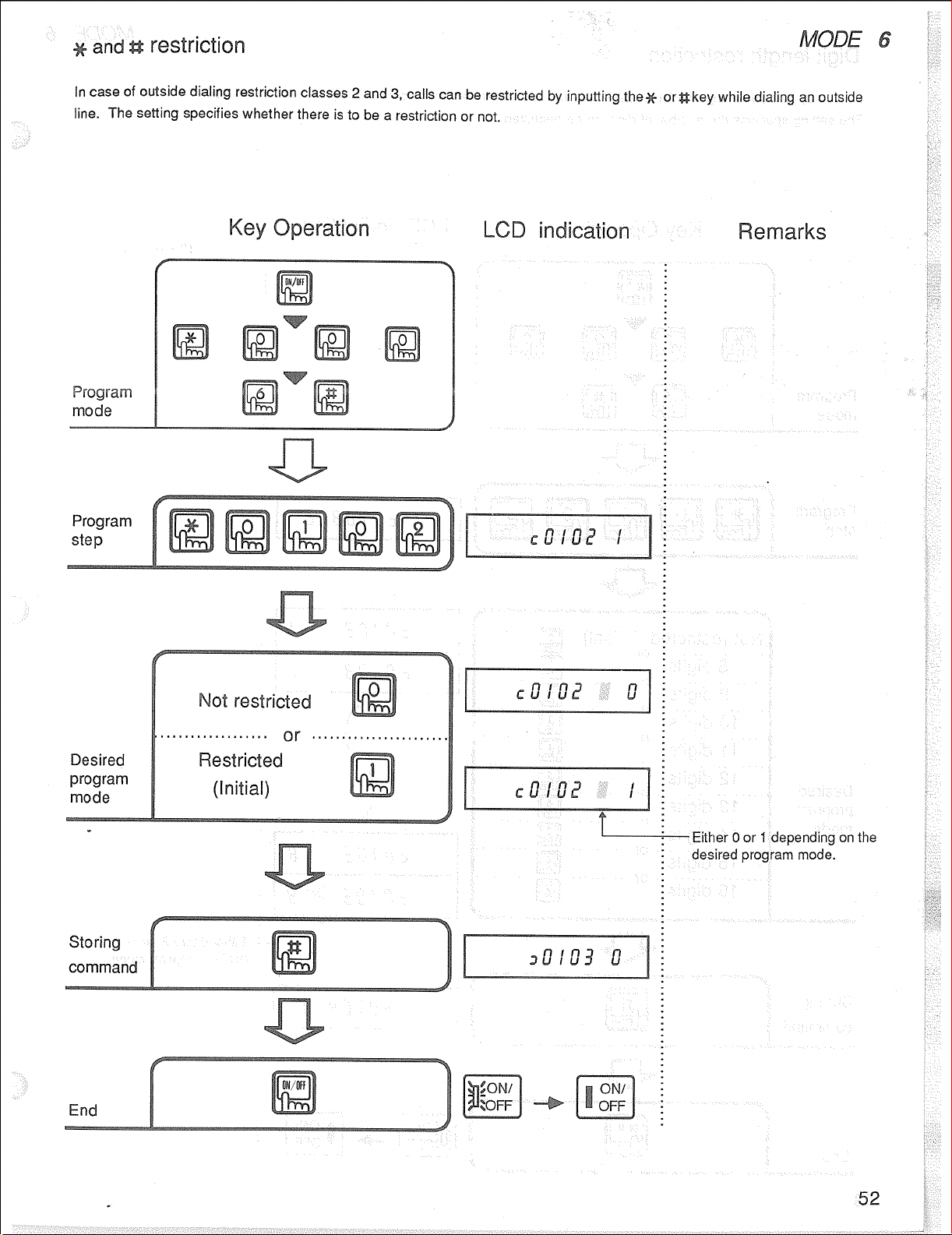
Page 52

Page 53

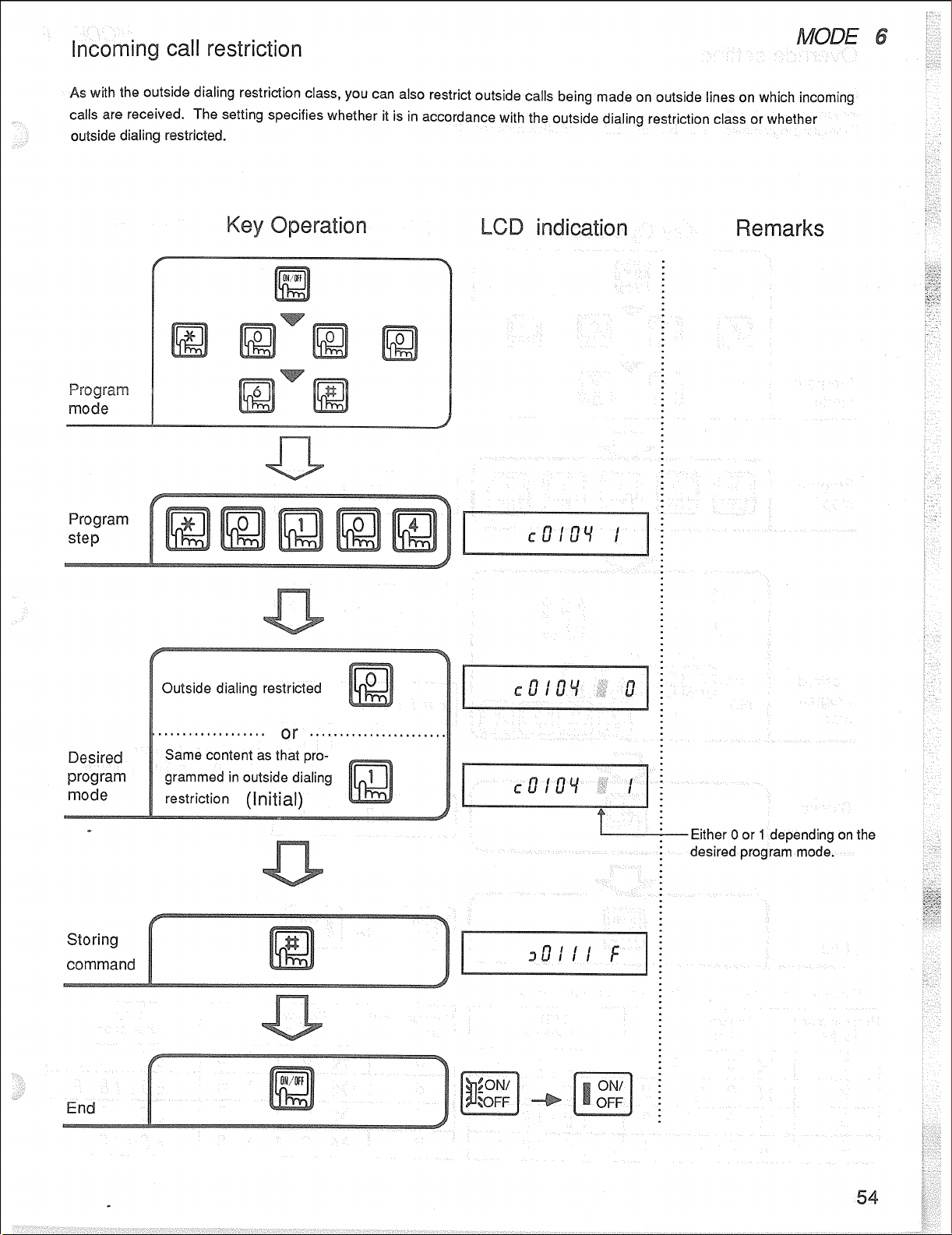
Page 54

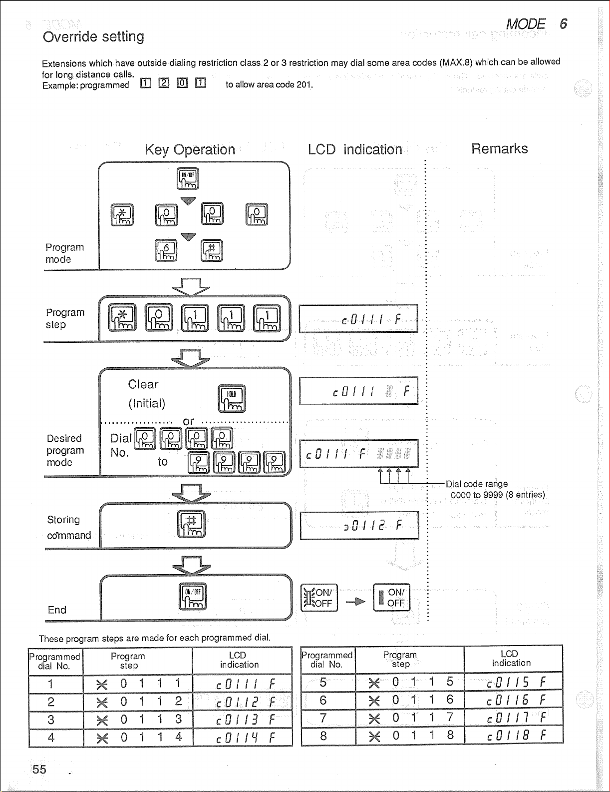
Page 55
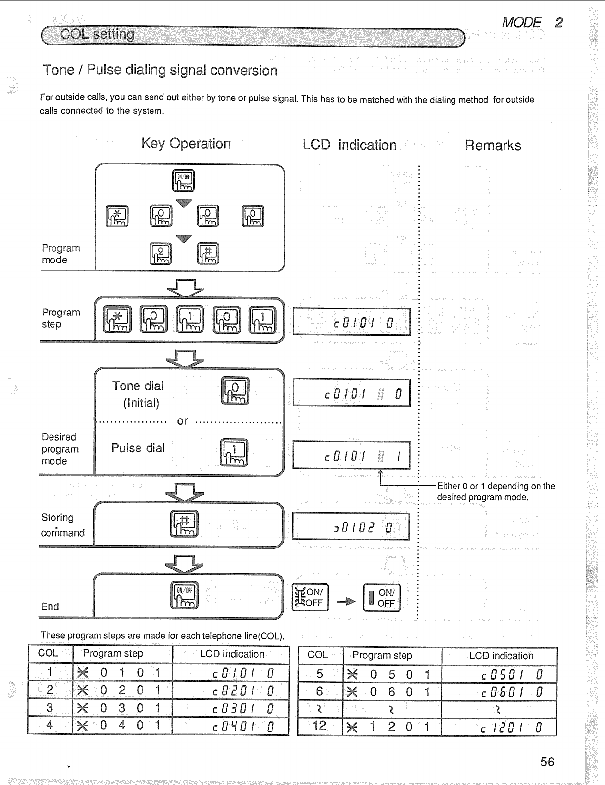
Page 56

Page 57
Page 58
Page 59
Page 60

Page 61

Page 62

Page 63

Page 64

Page 65

Page 66
Page 67
Page 68

Page 69

Page 70

Page 71

Page 72

Page 73

Page 74

Page 75
Page 76
Page 77

Page 78

Page 79

Page 80

Page 81

Page 82
Page 83

Page 84

Page 85

Page 86

Page 87

Page 88

Page 89

Page 90

Page 91
Page 92

Page 93
Page 94

Page 95

Page 96

Page 97

Page 98

Page 99

Page 100

 Loading...