

Page 1
U-72MF1U9
Order No. TD831158-11CE
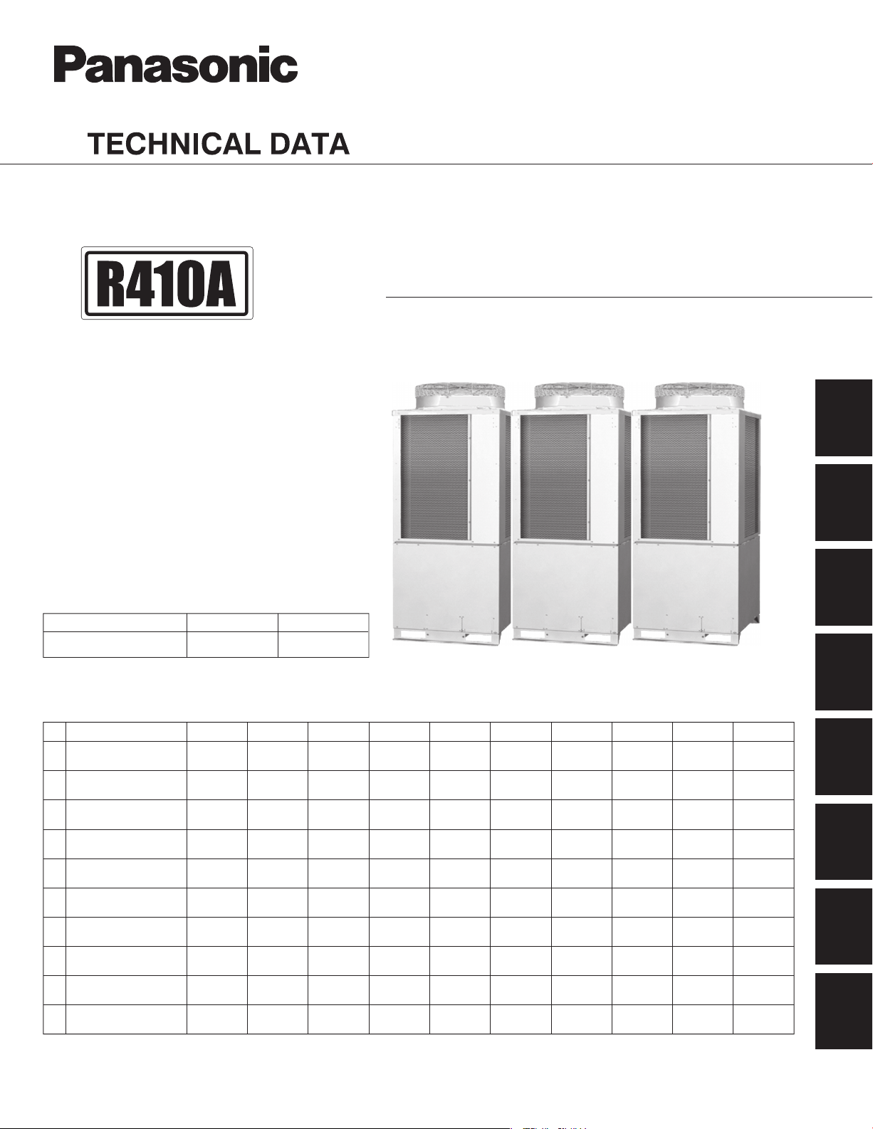
3WAY VRF System
U-72MF1U9E
*
U-96MF1U9
U-96MF1U9E
Model No.
Outdoor Unit
Model Name
Refrigerant R410A is used in the outdoor units.
* Salt-Air Damage Resistant Specifications.
Indoor Units
Class 24 36 48 54
U1
4-Way Cassette
4-Way Cassette 60×60
Y1
U-72MF1U9
U-72MF1U9E* U-96MF1U9E*
7 9 12 15 18
*
9672Class
U-96MF1U9
S-12MY1U6 S-18MY1U6
19
Section
1
2
3
4
S-24MU1U6 S-36MU1U6S-12MU1U6 S-18MU1U6
5
D1
1-Way Cassette
Low Silhouette Ducted
F1
Slim Low Static Ducted
M1
High Static Pressure
E1
Ducted
Ceiling
T1
Wall Mounted
K1
Floor Standing
P1
Concealed Floor
R1
Standing
** Necessary to install the External Electronic Expansion Valve Kit (Optional:CZ-P56SVK1U)
85464869258002
S-07MD1U6 S-09MD1U6 S-12MD1U6
S-07MF1U6 S-09MF1U6 S-12MF1U6 S-15MF1U6 S-18MF1U6
S-07MM1U6 S-09MM1U6 S-12MM1U6
S-12MT1U6 S-18MT1U6 S-24MT1U6
S-07MK1U6 S-09MK1U6 S-12MK1U6
S-07MP1U6 S-09MP1U6 S-12MP1U6 S-15MP1U6 S-18MP1U6 S-24MP1U6
S-07MR1U6 S-09MR1U6 S-12MR1U6 S-15MR1U6 S-18MR1U6 S-24MR1U6
S-15MM1U6 S-18MM1U6
S-18MK1U6
S-19MS1U6**S-24MK1U6
S-24MF1U6
REFERENCE NO.
S-36MF1U6 S-48MF1U6
S-36ME1U6 S-48ME1U6
TD831158-02
S-54MF1U6
6
7
8
Page 2
IMPORTANT!
Please Read Before Starting
This air conditioning system meets strict safety and
operating standards. As the installer or service person, it
is an important part of your job to install or service the
system so it operates safely and efficiently.
For safe installation and trouble-free operation, you
must:
Carefully read this instruction booklet before beginning.
Follow each installation or repair step exactly as shown.
Observe all local, state, and national electrical codes.
Pay close attention to all warning and caution notices
given in this manual.
This symbol refers to a hazard or
WARNING
CAUTION
If Necessary, Get Help
These instructions are all you need for most installation
sites and maintenance conditions. If you require help for a
special problem, contact our sales/service outlet or your
certified dealer for additional instructions.
In Case of Improper Installation
The manufacturer shall in no way be responsible for
improper installation or maintenance service, including
failure to follow the instructions in this document.
SPECIAL PRECAUTIONS
WARNING
Do not supply power to the unit until all wiring and tubing •
are completed or reconnected and checked.
Highly dangerous electrical voltages are used in this •
system. Carefully refer to the wiring diagram and these
instructions when wiring. Improper connections and
inadequate grounding can cause accidental injury or
death.
•
Ground the unit following local electrical codes.
Connect all wiring tightly. Loose wiring may cause •
overheating at connection points and a possible fire
hazard.
To prevent possible hazards from insulation failure, •
the unit must be grounded.
When Transporting
Be careful when picking up and moving the indoor and
outdoor units. Get a partner to help, and bend your knees
when lifting to reduce strain on your back. Sharp edges or
When Wiring
ELECTRICAL SHOCK CAN CAUSE
SEVERE PERSONAL INJURY OR DEATH.
ONLY A QUALIFIED, EXPERIENCED
ELECTRICIAN SHOULD ATTEMPT TO
WIRE THIS SYSTEM.
unsafe practice which can result
in severe personal injury or death.
This symbol refers to a hazard or
unsafe practice which can result
in personal injury or product or
property damage.
thin aluminum fins on the air conditioner can cut your
fingers.
When Installing…
Select an installation location which is rigid and strong
enough to support or hold the unit, and select a location
for easy maintenance.
…In a Room
Properly insulate any tubing run inside a room to prevent
“sweating” that can cause dripping and water damage to
walls and floors.
Keep the fire alarm and the air
CAUTION
…In Moist or Uneven Locations
Use a raised concrete pad or concrete blocks to provide a
solid, level foundation for the outdoor unit. This prevents
water damage and abnormal vibration.
…In an Area with High Winds
Securely anchor the outdoor unit down with bolts and a
metal frame. Provide a suitable air baffle.
…In a Snowy Area (for Heat Pump-type Systems)
Install the outdoor unit on a raised platform that is higher
than drifting snow. Provide snow vents.
outlet at least 5 feet away from the
unit.
When Connecting Refrigerant Tubing
Ventilate the room well, in the event that is refrigerant •
gas leaks during the installation. Be careful not to allow
contact of the refrigerant gas with a flame as this will
cause the generation of poisonous gas.
Keep all tubing runs as short as possible.•
Use the flare method for connecting tubing.•
Apply refrigerant lubricant to the matching surfaces of •
the flare and union tubes before connecting them, then
tighten the nut with a torque wrench for a leak-free
connection.
Check carefully for leaks before starting the test run.•
When performing piping work do •
not mix air except for specified
refrigerant (R410A) in refrigeration
cycle. It causes capacity down,
and risk of explosion and injury
due to high tension inside the
WARNING
Do not leak refrigerant while piping work for an •
installation or re-installation, and while repairing
refrigeration parts.
Handle liquid refrigerant carefully as it may cause
frostbite.
refrigerant cycle.
Refrigerant gas leakage may •
cause fire.
Do not add or replace refrigerant •
other than specified type. It may
cause product damage, burst and
injury etc.
i
Page 3
When Servicing
Turn the power OFF at the main power box (mains) •
before opening the unit to check or repair electrical
parts and wiring.
Keep your fingers and clothing away from any moving •
parts.
Clean up the site after you finish, remembering to check •
that no metal scraps or bits of wiring have been left
inside the unit being serviced.
WAR NI NG
Do not clean inside the indoor and •
outdoor units by users. Engage
authorized dealer or specialist for
cleaning.
In case of malfunction of this •
appliance, do not repair by yourself.
Contact to the sales dealer or service
dealer for a repair.
Others
CAUTION
CAUTION
Do not touch the air inlet or the
•
sharp aluminum fins of the
outdoor unit. You may get injured.
Ventilate any enclosed areas when •
installing or testing the refrigeration
system. Escaped refrigerant gas, on
contact with fire or heat, can produce
dangerously toxic gas.
Confirm after installation that no •
refrigerant gas is leaking. If the gas
comes in contact with a burning stove,
gas water heater, electric room heater
or other heat source, it can cause the
generation of poisonous gas.
Do not touch the air inlet or the
•
sharp aluminum fins of the
outdoor unit. You may get injured.
Do not sit or step on the unit, •
you may fall down accidentally.
Do not stick any object into the •
FAN CASE.
You may be injured and the unit
may be damaged.
Check of Density Limit
The room in which the air conditioner is to be
installed requires a design that in the event of
refrigerant gas leaking out, its density will not
exceed a set limit.
The refrigerant (R410A), which is used in the air
conditioner, is safe, without the toxicity or combustibility
of ammonia, and is not restricted by laws imposed to
protect the ozone layer. However, since it contains more
than air, it poses the risk of suffocation if its density
should rise excessively. Suffocation from leakage of
refrigerant is almost non-existent.
With the recent increase in the number of high density
buildings, however, the installation of multi air
conditioner systems is on the increase because of the
need for effective use of floor space, individual control,
energy conservation by curtailing heat and carrying
power, etc.
Most importantly, the multi air conditioner system is able
to replenish a large amount of refrigerant compared to
conventional individual air conditioners. If a single unit of
the multi air conditioner system is to be installed in a
small room, select a suitable model and installation
procedure so that if the refrigerant accidentally leaks
out, its density does not reach the limit (and in the event
of an emergency, measures can be made before injury
can occur).
ASHRAE and the International Mechanical Code of the
ICC as well as CSA provide guidance and define
safeguards related to the use of refrigerants, all of which
define a Refrigerant Concentration Level (RCL) of 25
pounds per 1,000 cubic feet for R410A refrigerant.
For additional guidance and precautions related to
refrigerant safety, please refer to the following
documents:
International Mechanical Code 2009 (IMC-2009)
(or more recently revised)
ASHRAE 15
ASHRAE 34
ii
Page 4
Precautions for Installation Using New Refrigerant
1. Care regarding tubing
1-1. Process tubing
Material: Use C1220 phosphorous deoxidized copper specified in JIS H3300 “Copper and Copper Alloy Seamless
Pipes and Tubes.”
For tubes of ø7/8" (ø22.22 mm) or larger, use C1220 T-1/2H material or H material, and do not bend the tubes.
Tubing size: Be sure to use the sizes indicated in the table below.
Use a tube cutter when cutting the tubing, and be sure to remove any flash. This also applies to distribution joints
(optional).
When bending tubing, use a bending radius that is 4 times the outer diameter of the tubing or larger.
Use sufficient care in handling the tubing. Seal the tubing ends with caps or tape to
Copper tube
Copper tube
CAUTION
Outer diameter 1/4 (6.35) 3/8 (9.52) 1/2 (12.7) 5/8 (15.88) 3/4 (19.05)
Wall thickness 1/32 (0.8) 1/32 (0.8) 1/32 (0.8) 5/128 (1.0)
Material
Outer diameter
Wall thickness
prevent dirt, moisture, or other foreign substances from entering. These substances
can result in system malfunction.
Unit: in. (mm)
OMaterial
over 5/128 (1.0)
Unit: in. (mm)
1/2 H, H
7/8 (22.22) 1-1/8 (28.58) 1-3/8 (34.92) 1-5/8 (41.28)
5/128 (1.0) 5/128 (1.0) 3/64 (1.1) over
3/64 (1.20)
1-2.
Prevent impurities including water, dust and oxide from entering the tubing. Impurities can cause R410A
refrigerant deterioration and compressor defects. Due to the features of the refrigerant and refrigerating machine
oil, the prevention of water and other impurities becomes more important than ever.
2. Be sure to recharge the refrigerant only in liquid form.
2-1.
Since R410A is a non-azeotrope, recharging the refrigerant in gas form can lower performance and cause defects
in the unit.
2-2. nce decreases when gas leaks, collect the remaining
Since refrigerant composition changes and performa
refrigerant and recharge the required total amount of new refrigerant after fixing the leak.
3. Different tools required
3-1.
Tool specifications have been changed due to the characteristics of R410A.
Some tools for R22- and R407C-type refrigerant systems cannot be used.
R407C tools
New
Item
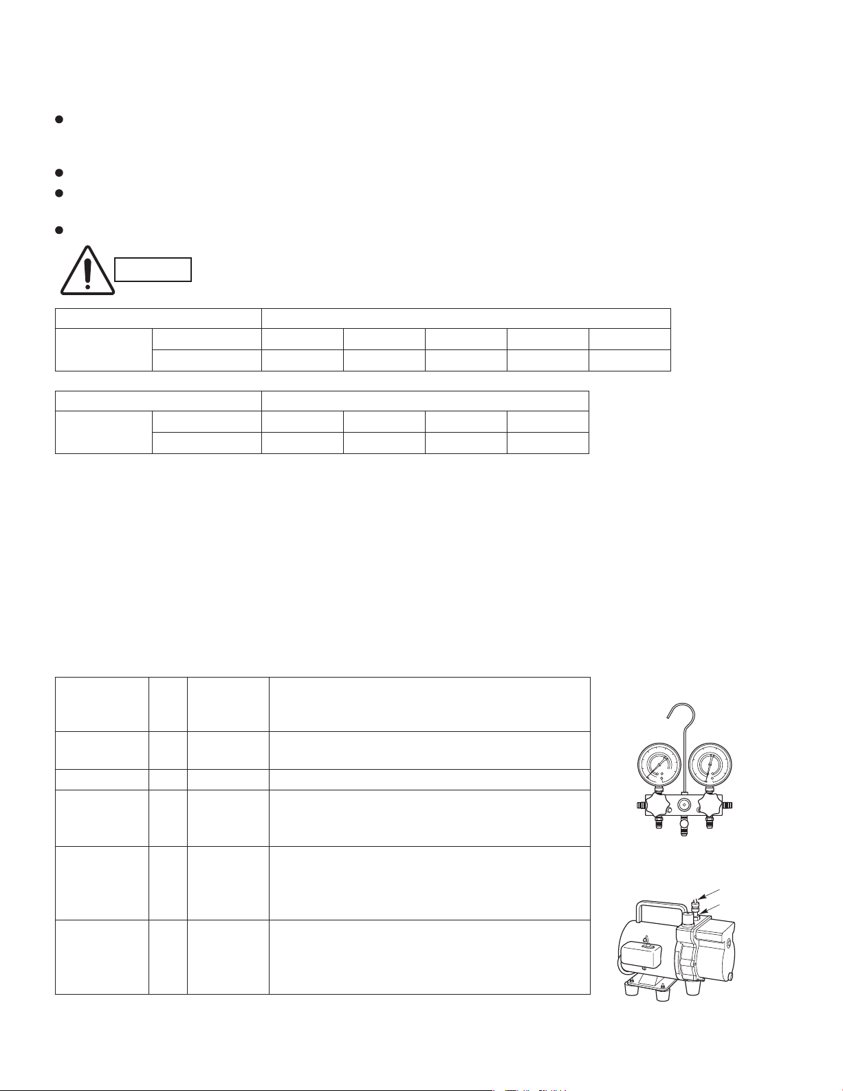
Manifold gauge Yes No Types of refrigerant, refrigerating machine
Charge hose Yes
Vacuum pump Use a conventional vacuum pump if it is equipped
Leak detector Leak detectors for CFC and HCFC that
Flaring oil For systems that use R22, apply mineral oil (Suniso oil)
* Using tools for R22 and R407C and new tools for R410A together can cause defects.
compatible
tool?
with R410A?
Yes
Yes No
Yes No
No
Yes
oil, and pressure gauge are different.
To resist higher pressure, material must be changed.
with a check valve. If it has no check valve,
purchase and attach a vacuum pump adapter.
react to chlorine do not function because
R410A contains no chlorine. Leak detector
for HFC134a can be used for R410A.
to the flare nuts on the tubing to prevent refrigerant
leakage. For machines that use R407C or R410A, apply
synthetic oil (ether oil) to the flare nuts.
Remarks
Manifold gauge
Vacuum pump
Outlet
Inlet
iii
Page 5
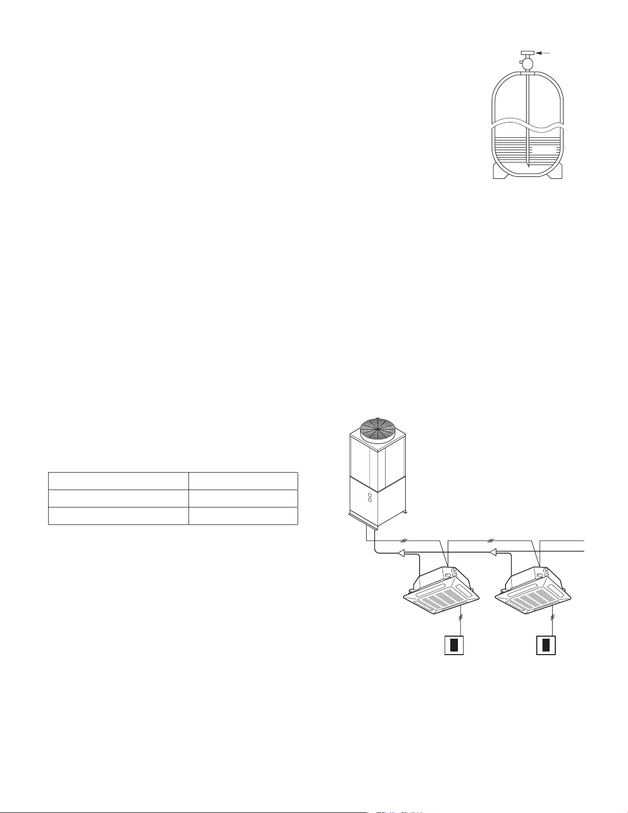
3-2. Use R410A exclusive cylinder only.
New refrigerant R410A cannot be used for
earlier models
1. Compressor specifications are different.
If recharging a R22 or R407C compressor with R410A,
durability will significantly decrease since some of the
materials used for compressor parts are different.
2. Existing tubing cannot be used (especially R22).
Completely cleaning out residual refrigerating
machine oil is impossible, even by flushing.
Val ve
Single-outlet valve
(with siphon tube)
Liquid refrigerant should be recharged
with the cylinder standing on end as
shown.
Liquid
3. Refrigerating machine oil differs (R22).
Since R22 refrigerating machine oil is mineral oil, it
does not dissolve in R410A. Therefore, refrigerating
machine oil discharged from the compressor can cause
compressor damage.
R22 refrigerating machine oil Mineral oil (Suniso oil)
R407C refrigerating machine oil Synthetic fluid (ether oil)
R410A refrigerating machine oil Synthetic fluid (ether oil)
iv
Page 6

Contents
Section 1: OUTLINE OF 3WAY VRF SYSTEM ......................................................................
Line-up ............................................................................................................
1. 1-2
Features of 3WAY VRF SYSTEM ....................................................................
2. 1-4
Salt-Air Damage Resistant Specifications .......................................................
3. 1-7
Section 2: DESIGN OF 3WAY VRF SYSTEM ........................................................................
Model Selecting and Capacity Calculator .......................................................
1. 2-2
System Design .............................................................................................
2. 2-18
3. 2-24
Electrical Wiring ............................................................................................
4. 2-32
Installation Instructions .................................................................................
5. 2-40HOW TO PROCESS TUBING ......................................................................
6. 2-44AIR PURGING ..............................................................................................
7. 2-47Optional Parts ...............................................................................................
Section 3: Control of 3WAY VRF SYSTEM ...........................................................................
Main Operating Functions
1.
Wireless Remote Controller
2.
Timer Remote Controller
3.
Simplified Remote Controller
4.
System Controller
5.
Schedule Timer
6.
Intelligent Controller (CZ-256ESMC1U)
7.
Communication Adaptor (CZ-CFUNC1U)
8.
Remote Sensor
9.
LonWorks Interface (CZ-CLNC1U)
10.
Refer to the 2WAY VRF SYSTEM TECHNICAL DATA (TD831157)
*
Section 4: 3WAY VRF SYSTEM UNIT SPECIFICATIONS .....................................................
Outdoor Unit ..................................................................................................
1.
2.
4-Way Cassette Type (U1 Type)
3.
4-Way Cassette 60×60 Type (Y1 Type)
4.
1-Way Cassette Type (D1 Type)
5.
Low Silhouette Ducted Type (F1 Type)
6.
Slim Low Static Ducted Type (M1 Type)
7.
High Static Pressure Ducted Type (E1 Type)
8.
Ceiling Type (T1 Type)
9.
Wall Mounted Type (K1 Type)
10.
Floor Standing Type (P1 Type)
11. Concealed Floor Standing Type (R1 Type)
12. Intaking Fresh Air of 4-Way Casstte Type and Slim Low Static Ducted Type
Refer to the 2WAY VRF SYSTEM TECHNICAL DATA (TD831157)
Section 5: TEST RUN .............................................................................................................
Section 6: ELECTRICAL DATA ..............................................................................................
Section 7: PCB AND FUNCTIONS ........................................................................................
Section 8: CAPACITY TABLE ................................................................................................
*
1. 5-2
Preparing for Test Run ....................................................................................
2. 5-3
Test Run Procedure ........................................................................................
3. 5-4
Main Outdoor Unit PCB Setting ......................................................................
4. 5-6
Auto Address Setting ......................................................................................
5. 5-12
Remote Controller Test Run Settings ...........................................................
6. 5-12
Caution for Pump Down ................................................................................
7. 5-13
Meaning of Alarm Messages ........................................................................
1. 6-2
Outdoor Unit ...................................................................................................
2.
Indoor Unit
Refer to the 2WAY VRF SYSTEM TECHNICAL DATA (TD831157)
*
1. 7-2
Outdoor Unit Control PCB ...............................................................................
2.
Indoor Unit Control PCB Switches and Functions
Refer to the 2WAY VRF SYSTEM TECHNICAL DATA (TD831157)
*
1. 8-2
Capacity Ratio of Outdoor Unit ......................................................................
2. 8-10
Cooling Capacity of Indoor Unit ....................................................................
vi
1-1
2-1
3-1
4-1
4-3
5-1
6-1
7-1
8-1
Page 7

Outline of 3WAY VRF SYSTEM
2
Contents
1. OUTLINE OF 3WAY VRF SYSTEM
1. Line-up ............................................................................................................................... 1-2
. Features of 3WAY VRF SYSTEM .......................................................................................
3. Salt-Air Damage Resistant Specifications .......................................................................
1-4
1-7
1
2
3
4
5
6
7
1 - 1
8
Page 8
Outline of 3WAY VRF SYSTEM
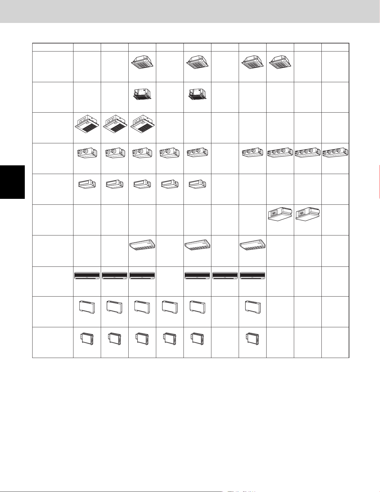
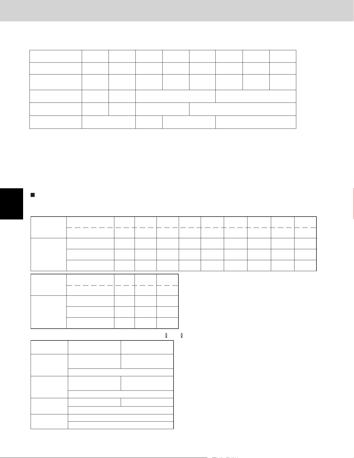
1. Line-up
Indoor units
Type 9 191815127 3624 48 54
4-Way Cassette
(U1 Type)
4-Way Cassette
60 X 60
(Y1 Type)
1-Way Cassette
(D1 Type)
Low Silhouette
Ducted
(F1 Type)
S-07MD1U6 S-09MD1U6 S-12MD1U6
S-07MF1U6 S-12MF1U6 S-15MF1U6 S-18MF1U6S-09MF1U6 S-24MF1U6
S-12MU1U6 S-18MU1U6
S-12MY1U6 S-18MY1U6
S-24MU1U6 S-36MU1U6
S-36MF1U6 S-48MF1U6 S-54MF1U6
1
2
3
4
5
Slim Low Static
Ducted
(M1 Type)
High Static
Pressure Ducted
(E1 Type)
Ceiling
(T1 Type)
Wall Mounted
(K1 Type)
Floor Standing
(P1 Type)
Concealed Floor
Standing
(R1 Type)
S-07MM1U6 S-12MM1U6 S-15MM1U6 S-18MM1U6S-09MM1U6
S-18MT1U6S-12MT1U6 S-24MT1U6
S-07MK1U6 S-09MK1U6 S-12MK1U6
S-07MP1U6 S-12MP1U6 S-15MP1U6 S-18MP1U6S-09MP1U6 S-24MP1U6
S-07MR1U6 S-12MR1U6 S-15MR1U6 S-18MR1U6S-09MR1U6 S-24MR1U6
S-19MS1U6
*
S-24MK1U6S-18MK1U6
S-36ME1U6
S-48ME1U6
6
7
8
* Necessary to install the External Electronic Expansion Valve Kit (Optional:CZ-P56SVK1U).
1 - 2
Page 9
1. Line-up
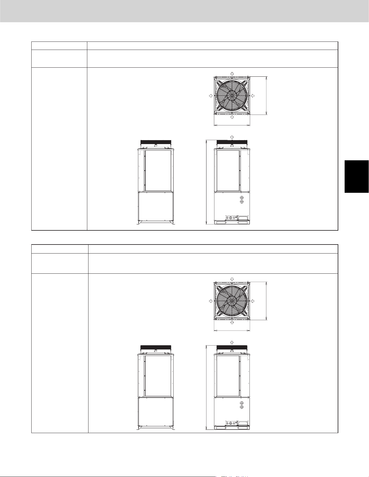
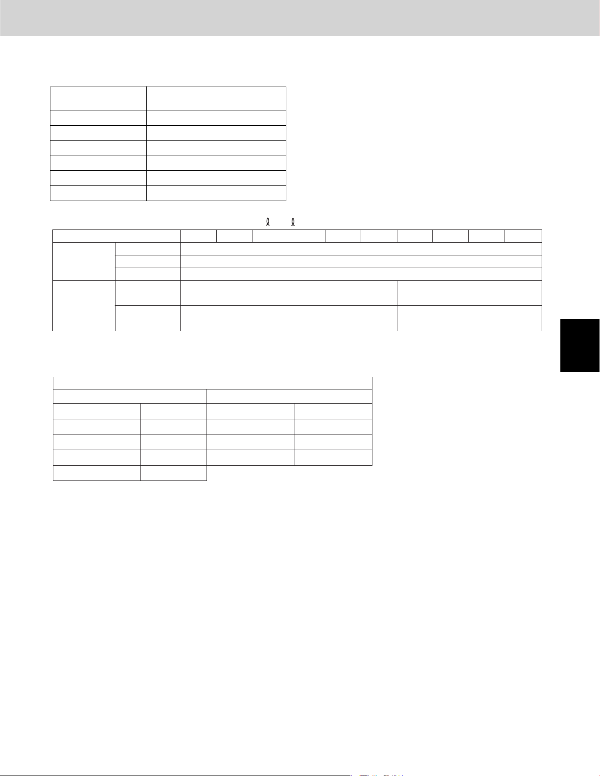
Outdoor units
Type
Capacity: BTU/h (kW)
Cooling / Heating
U-72MF1U9
U-72MF1U9E
Outline of 3WAY VRF SYSTEM
72
72,000 (21.1)
/ 81,000 (23.7)
*
Air
intake
Air intake
Air
intake
37-1/2
Outdoor Unit
Type
Capacity: BTU/h (kW)
Cooling / Heating
U-96MF1U9
U-96MF1U9E
Air
intake
(Ceiling panel dimensions)
35
Air discharge
(Maximum dimensions)
1
82-9/16
2
unit : in.
96
96,000 (28.1)
/ 108,000 (31.6)
*
Air
intake
Air intake
Air
intake
37-1/2
3
4
Air
intake
Outdoor Unit
Outdoor unit model name ended with letters "U9E". Refer to the Section 1 "3. Salt-Air Damage Resistant Specifications".
*
1 - 3
(Ceiling panel dimensions)
82-9/16
35
Air discharge
(Maximum dimensions)
unit : in.
5
6
7
8
Page 10
2. Features of 3WAY VRF SYSTEM
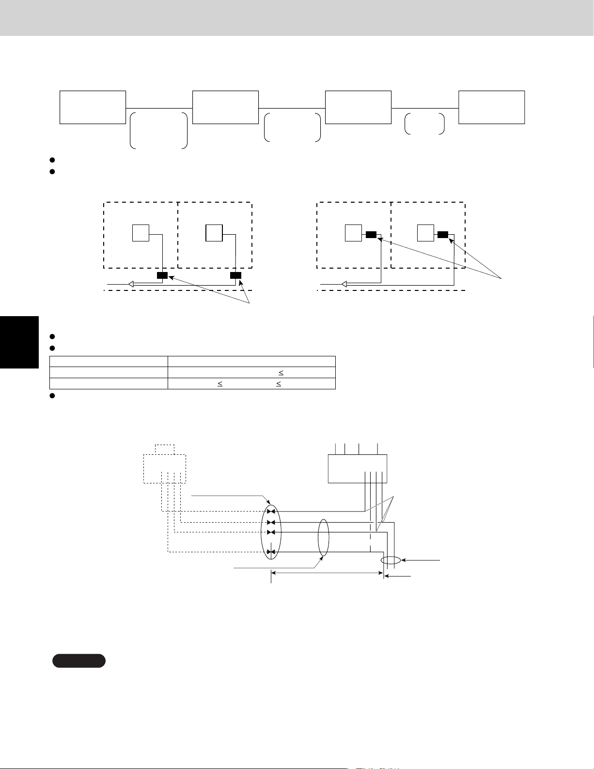
2-1. Outline of 3WAY VRF SYSTEM
System example
CONCENTRATION
Outline of 3WAY VRF SYSTEM
Since all pipings are concentrated
into one pipe shaft, you can minimize
piping space and construction labor
1
2
3
4
CONNECTION
System limitations
Maximum number of combined outdoor units
Maximum tonnage of combined outdoor units
Maximum number of connectable indoor units
Indoor/outdoor unit capacity ratio
Maximum actual piping length
Maximum level difference (when outdoor unit is lower)
Maximum total piping length
* Panasonic makes it possible to link outdoor
unit together for a large capacity (24-Ton).
If indoor/outdoor units need servicing, a ball
valve (field supply) cuts off non-operational
units to let other units stay running.
3
24-Ton
40
50~130%
492ft
164 (131) ft
984 ft
Solenoid
valve kit
Indoor unit
ADDITION
If your indoor capacity load changes in the future, it’s easy to
add on both indoor and outdoor units using the same pipings.
If the additional installment of outdoor and indoor units are
*
expected, the size of refrigerant piping should be decided
according to the total capacity after the addition.
5
6
7
8
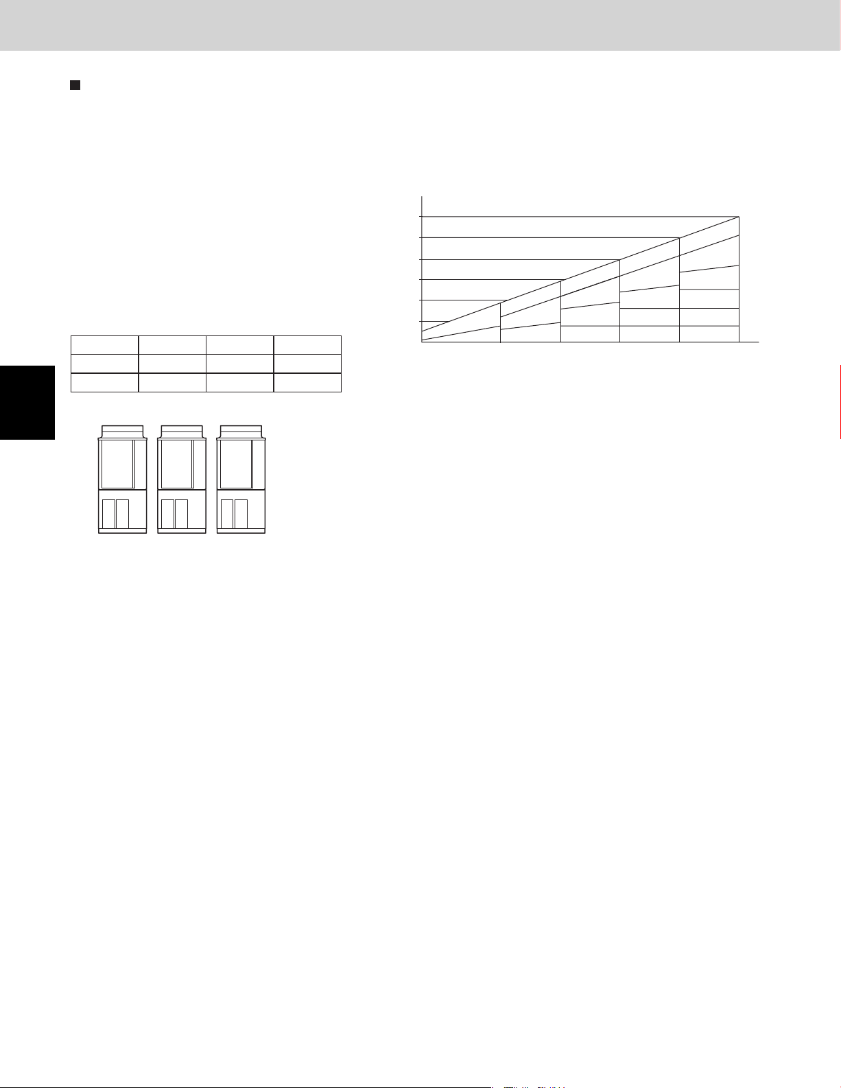
Combination of outdoor units
The DC inverter unit can be used independently or in combination.
CAUTION
Total
tonnage
Type (ton)
6
8
R407C models and R22 models must not be used in combination with each other.
6 8 12 14 18 20 22 24
1
11 231
12231
1 - 4
Page 11
2. Features of 3WAY VRF SYSTEM
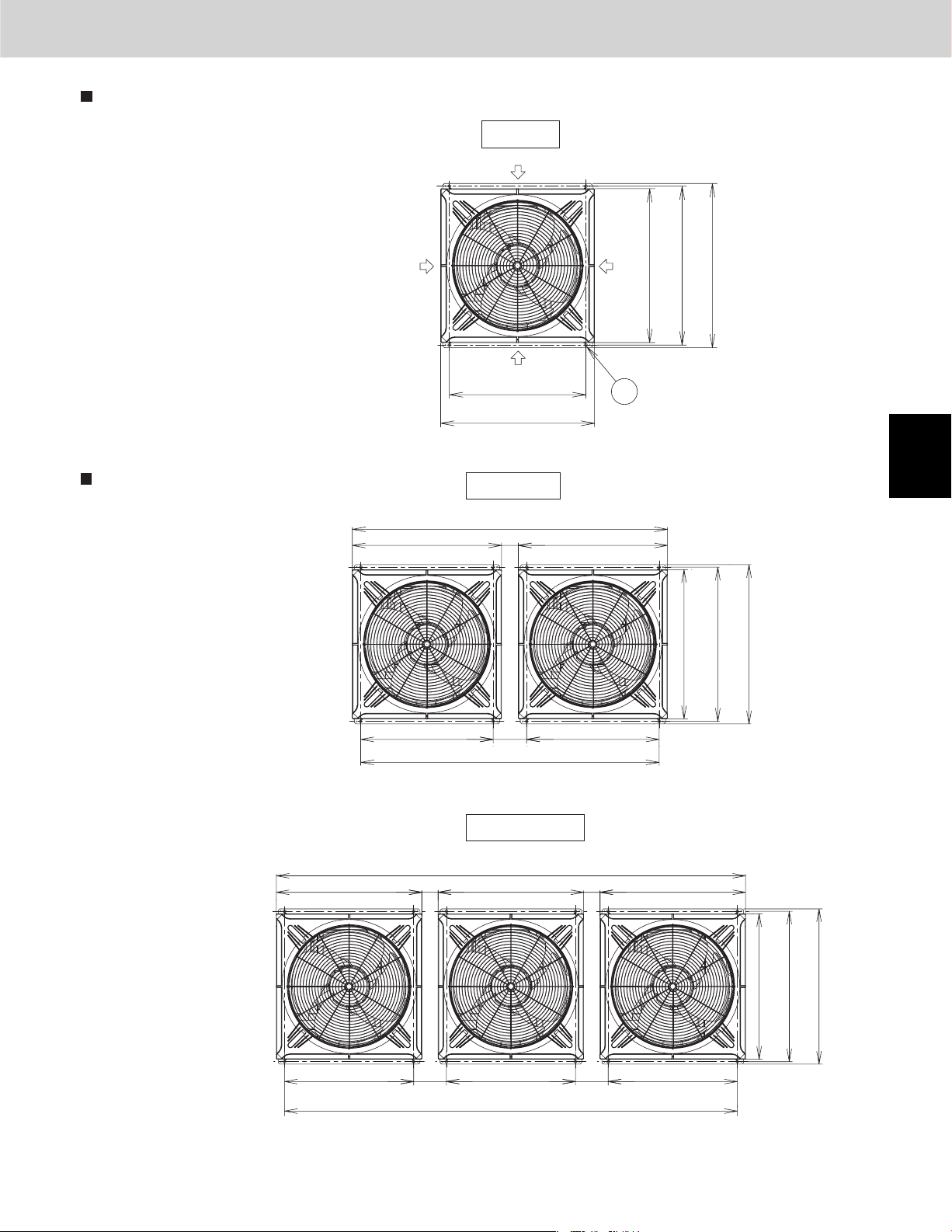
Dimensions
Outline of 3WAY VRF SYSTEM
6, 8 Ton
Air
intake
6-Ton
8-Ton
U-72MF1U9, U-72MF1U9E
U-96MF1U9, U-96MF1U9E
Dimensions of unit combinations
*
*
Air
intake
74 (Ceiling panel dimensions)
35
(Ceiling panel dimensions)
Air
intake
31-1/8
(Installation hole pitch)
35
(Ceiling panel dimensions)
Top view
12, 14 Ton
4
(Ceiling panel dimensions)
Air
intake
35
35
37-1/2
36-1/4
(Installation hole pitch)
(Ceiling panel dimensions)
4
35
(Maximum dimensions)
Unit: in.
36-1/4
37-1/2
1
2
3
(Installation hole pitch)
35
(Ceiling panel dimensions)
(Installation hole pitch)
31-1/8
7-7/8
(Installation hole pitch)
70-1/8
(Installation hole pitch)
Top view
18, 20, 22, 24 Ton
113 (Ceiling panel dimensions)
(Ceiling panel dimensions)
(Installation hole pitch)
109-1/16 (Installation hole pitch)
35
31-1/8
Top view
31-1/8
44
(Ceiling panel dimensions)
8/7-78/7-731-1/8
(Installation hole pitch)
35
31-1/8
(Installation hole pitch)
(Ceiling panel dimensions)
(Maximum dimensions)
Unit: in.
35
36-1/4
37-1/2
(Installation hole pitch)
(Ceiling panel dimensions)
Unit: in.
4
5
6
7
(Maximum dimensions)
8
*
Outdoor unit model name ended with letters "U9E". Refer to the Section 1 "3. Salt-Air Damage Resistant Specifications".
1 - 5
Page 12
Outline of 3WAY VRF SYSTEM
2. Features of 3WAY VRF SYSTEM
Capacity control
The compressor combination (DC inverter compressor + constant-speed compressor) allows smooth capacity control from
0.6-Ton to 24-Ton.
1
2
3
Realization of smooth capacity control
from 0.6-Ton to 24-Ton
Capacity control is possible smoothly with a DC
inverter compressor. The right graph shows the
image of the operating combination of compressors in case of 24-Ton system. In actual operation,
the combination will be changed by operating
condition, operating time amount, priority of compressor and so on.
Comp. HP Unit1(main) Unit2(sub1) Unit3(sub2)
DC comp. 4.0 4.0 4.0
AC comp. 5.0 5.0 5.0
*24 Ton = U-96MF1U9 (U-96MF1U9E) Type x 3
Unit 1
DC1
AC1
Unit 2
DC2
AC2
Unit 3
DC3
AC3
Capacity
(Ton)
24
20
16
12
In case of 24-Ton system
DC1
DC1
DC1
8
4
DC1
DC2
DC1
DC2
DC3
Example of 3 unit connection
DC2
DC3
AC1
DC2
DC3
AC1
AC2
LOAD
DC2
DC3
AC1
AC2
AC3
---
>
4
5
6
7
8
1 - 6
Page 13

3. Salt-Air Damage Resistant Specifi cations
Specifications
Relevant Parts Material Standard Specifications
Outline of 3WAY VRF SYSTEM
Salt-Air Damage Resistant
Specifications
Outdoor unit model name ended
with letters "U9E".
Outer box/side plate/
drain pan
between the stud
Base frame
Fan guard
Fin Aluminum
Tube Copper No treatment Zinc rich treatment (whole)
Tube plate
Exchanger
Heat
Propeller fan
Fan
Installation frame
Electrical component box
Tapping screws
Hot-dip zinc-coated
steel sheet
Hot-dip aluminum-zinc
coated steel sheet
Resin (Polypropylene) No treatment
Hot-dip zinc-coated
steel sheet
Resin
Aluminum
Hot-dip zinc-coated
steel sheet
--
Hot-dip zinc-coated
steel sheet
Hot-dip zinc-coated
steel sheet
SUS410
Polyester powder double coating
(both sides)( m)40
No treatment
No treatment
No treatment
No treatment
No treatment
No treatment
Motor maker's standard spec.Motor
Polyester powder double coating
(both sides) m)120(
No treatment
Hexavalent chromium-free
coating
Polyester powder double coating
(both sides) ( m)120
Polyester powder double coating
(both sides) ( m)120
No treatment
Zinc rich treatment
Zinc rich treatment (whole)
No treatment
Urethane coating
Urethane coating
Motor maker's spec. for salt-air
damage resistant (urethane coating)
Polyester powder double coating
(both sides) 120 m)(
Polyester powder coating( 120 m)
Hexavalent chromium-free coating +
urethane coating
(m)30
(m)30
1
2
3
Stud supplementary
bracket
Accumulator
Receiver tank
Welded portion Copper tube No treatment Urethane coating
Outer surface Copper tube No treatment Urethane coating
Refrigeration
cycle tube
Fixing bracket
Notes:
1 Consult us before introducing a salt-air damage resistant model as it requires a special treatment.
2 The specifications are subject to change without notice for development.
3 Contact us for the delivery schedule.
Hot-dip zinc-coated
steel sheet
Steel Epoxy coating + alkyd coating
Hot-dip zinc-coated
steel sheet
No treatment
No treatment
No treatment
Polyester powder double coating
( 120 m)
Dessicant coating
Zinc rich double coating + urethane
coating m)70(
Polyester powder double coating
(both sides) m)80(
m) 30 (PC board --
4
5
6
7
8
1 - 7
Page 14

– MEMO –
1 - 8
Page 15

Design of 3WAY VRF SYSTEM
Contents
2. DESIGN OF 3WAY VRF SYSTEM
1. Model Selecting and Capacity Calculator ........................................................................2-2
2-21-1. Operating Range .............................................................................................................
2-31-2. Procedure for Selecting Models and Calculating Capacity ...........................................
2-41-3. Tubing Length .................................................................................................................
2-61-4. Tubing Size ......................................................................................................................
2-81-5. Installation Standards ......................................................................................................
2-91-6. Straight Equivalent Length of Joints ...............................................................................
2-101-7. Check of limit density ....................................................................................................
2-11................................................................8-1 Calculation of Actual Capacity of Indoor Unit
2-15................................9-1 Capacity Correction Graph According to Temperature Condition
2-161-10. ...Capacity Correction Graph According to Tubing Length and Elevation Difference
................................................................................................................. 2-182. System Design
2-182-1. System Example............................................................................................................
2-20.......2-2. Example of Tubing Size Selection for Extension and Additional Charge Amount
2-23............................................................................................2-3. Installing Distribution Joint
2-243. Electrical Wiring ..............................................................................................................
2-243-1. General Precautions on Wiring .....................................................................................
Recommended Wire Length and Wire Diameter for Power Supply System ..................
4-5. 2-33Precautions When Installing in Heavy Snow Areas ......................................................
4-6. Dimensions of Wind Ducting
4-7. Dimensions of Snow Ducting
Indoor Unit
Refer to the 2WAY VRF SYSTEM TECHNICAL DATA (TD831157)
*
Distribution Joint Kits
Solenoid Valve Kit for 3WAY VRF System ......................................................................
.....................................................................................................
2 - 1
2-243-2.
2-253-3. Wiring System Diagrams ...............................................................................................
2-283-4. Important Note When Wiring for Common Type ..........................................................
2-313-5. Important Note When Wiring for Y1 Type ....................................................................
2-324. Installation Instructions ..................................................................................................
2-32Outdoor Unit ..................................................................................................................
2-324-1. Selecting the Installation Site for Outdoor Unit ............................................................
2-33.....................................................................2-4 Removing Fin Guard for Heat Exchanger
2-33.......................................................................3-4 Shield for Horizontal Exhaust Discharge
2-33.........................................................4-4 Installing the Outdoor Unit in Heavy Snow Areas
2-34Reference diagram for air-discharge chamber (field supply).......................................
2-35Reference diagram for snow-proof ducting (field supply)............................................
2-364-8. Transporting the Outdoor Unit .....................................................................................
2-364-9. Installing the Outdoor Unit ............................................................................................
2-374-10. Remove the Brackets Used for Transport ..................................................................
2-374-11. Routing the Tubing ......................................................................................................
2-384-12. Prepare the Tubing......................................................................................................
2-384-13. Connect the Tubing.....................................................................................................
2-405. HOW TO PROCESS TUBING ..........................................................................................
2-405-1. Connecting the Refrigerant Tubing ..............................................................................
2-415-2. Connecting Tubing Between Indoor and Outdoor Units .............................................
2-425-3. Insulating the Refrigerant Tubing .................................................................................
2-435-4. Taping the Tubes ..........................................................................................................
2-435-5. Finishing the Installation ................................................................................................
2-446. AIR PURGING .................................................................................................................
2-44Air Purging with a Vacuum Pump (for Test Run) Preparation ..................................
2-477. Optional Parts ..................................................................................................................
2-477-1.
2-517-2.
1
2
3
4
5
6
7
8
Page 16
1. Model Selecting and Capacity Calculator
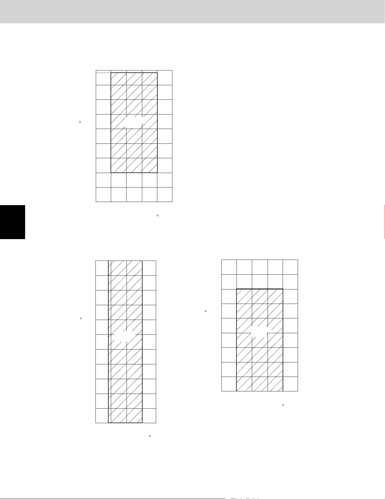
1-1. Operating Range
Heating and Cooling
77
75
68
59
Design of 3WAY VRF SYSTEM
1
2
3
4
50
41
32
23
14
Outdoor air intake temp. F (WB)
5
-4
50 59
Operating
range
68 77 86
Indoor air intake temp. F (DB)
Cooling
113
104
95
86
95
Heating
77
68
59
50
5
6
7
8
77
57
59
Operating
range
68 77
68
59
50
41
Outdoor air intake temp. F (DB)
32
23
14
50
Indoor air intake temp. F (WB)
41
32
23
14
Outdoor air intake temp. F (WB)
5
-4
50
Operating
range
68 77 86 95
59
Indoor air intake temp. F (DB)
86
2 - 2
Page 17

Design of 3WAY VRF SYSTEM
1. Model Selecting and Capacity Calculator
1-2. Procedure for Selecting Models and Calculating Capacity
Model Selection Procedure
Select the model and calculate the capacity for each refrigerant system according to the procedure shown below.
Calculation of the indoor air-conditioning load
Calculate the maximum air-conditioning load for each room or zone.
Selection of an air conditioning system
Select the ideal air conditioning system for air conditioning of each room or zone.
Design of the control system
Design a suitable control system for the selected air conditioning system.
Preliminary selection of indoor and outdoor units
Make preliminary selections that are within the allowable range for the system
Check of the tubing length and elevation difference
Check that the length of refrigerant tubing and the elevation difference are within the allowable
ranges.........................................................................................................................................
Calculation of the corrected outdoor unit capacity
Capacity correction coefficient for model................................................................................
Capacity correction coefficient for outdoor temperature conditions...........................
Capacity correction coefficient for tubing length and elevation difference........................
Heating capacity correction coefficient for frosting/defrosting..........................................
Calculation of the corrected capacity for each indoor unit
Capacity correction coefficient for indoor temperature conditions....................................
Capacity distribution ratio based on the tubing length and elevation difference..............
Calculation of the actual capacity for each indoor unit
Calculate the corrected indoor/outdoor capacity ratio, based on the corrected outdoor unit
capacity and the total corrected capacity of all indoor units in the same system. Use the result to
calculate the capacity correction coefficient for the indoor units.................................
Multiply the corrected capacity of each indoor unit by the capacity correction coefficient to calcu-
late the actual capacity for each indoor unit...........................................................................
Recheck of the actual capacity for each indoor unit
If the capacity is inadequate, reexamine the unit combinations.
Example 1: Increasing the outdoor unit capacity....................................................................
Example 2: Increasing the indoor unit capacity......................................................................
Increasing the tubing size........................................................................................................
Design of tubing
Create a tubing design which minimizes the amount of additional refrigerant charge as much as
possible...........................................................................................................................
If tubing extension for additional unit is expected in the future, create the tubing design with
adequate consideration for this extension.
Select the tubing size for the main tube (LA) up to the No. 1 distribution joint based on the rated
cooling capacity of the outdoor unit. Select tubing sizes after the distribution point based on the
total rated cooling capacity of the connected indoor units.
Increasing the tubing size of the wide tubes can reduce the loss of capacity caused by longer
tubing lengths. (Only the main wide tube with the largest tube diameter (main tube LA and main
tubes after the distribution point that are the same size as LA) can be changed.) In this case, it is
necessary to recalculate the actual indoor unit capacities.....................................................
Calculation of additional refrigerant charge amount
Calculate the additional refrigerant charge from the diameters and lengths of the refrigerant tubing. Even if the wide tubing diameter was increased, determine the additional refrigerant charge
based only on the narrow tubing size.....................................................................................
Check the minimum indoor capacity (limit density) with respect to the amount of refrigerant. If the
limit density is exceeded, be sure to install ventilation equipment or take other corrective steps.
Design of electrical wiring capacity
Select a wiring capacity according to the method of power supply.......................................
2 - 3
.
........
2-4 ~ 2-10
2-4
2-11
2-11, 13, 15
2-11, 14
2-11, 13
2-11, 14
2-11, 14
2-11 ~ 2-15
2-12
2-18
2-19
2-20
2-4 ~ 2-6
2-20
2-21
2-22
2-24
1
2
3
4
5
6
7
8
Page 18
Design of 3WAY VRF SYSTEM
1. Model Selecting and Capacity Calculator
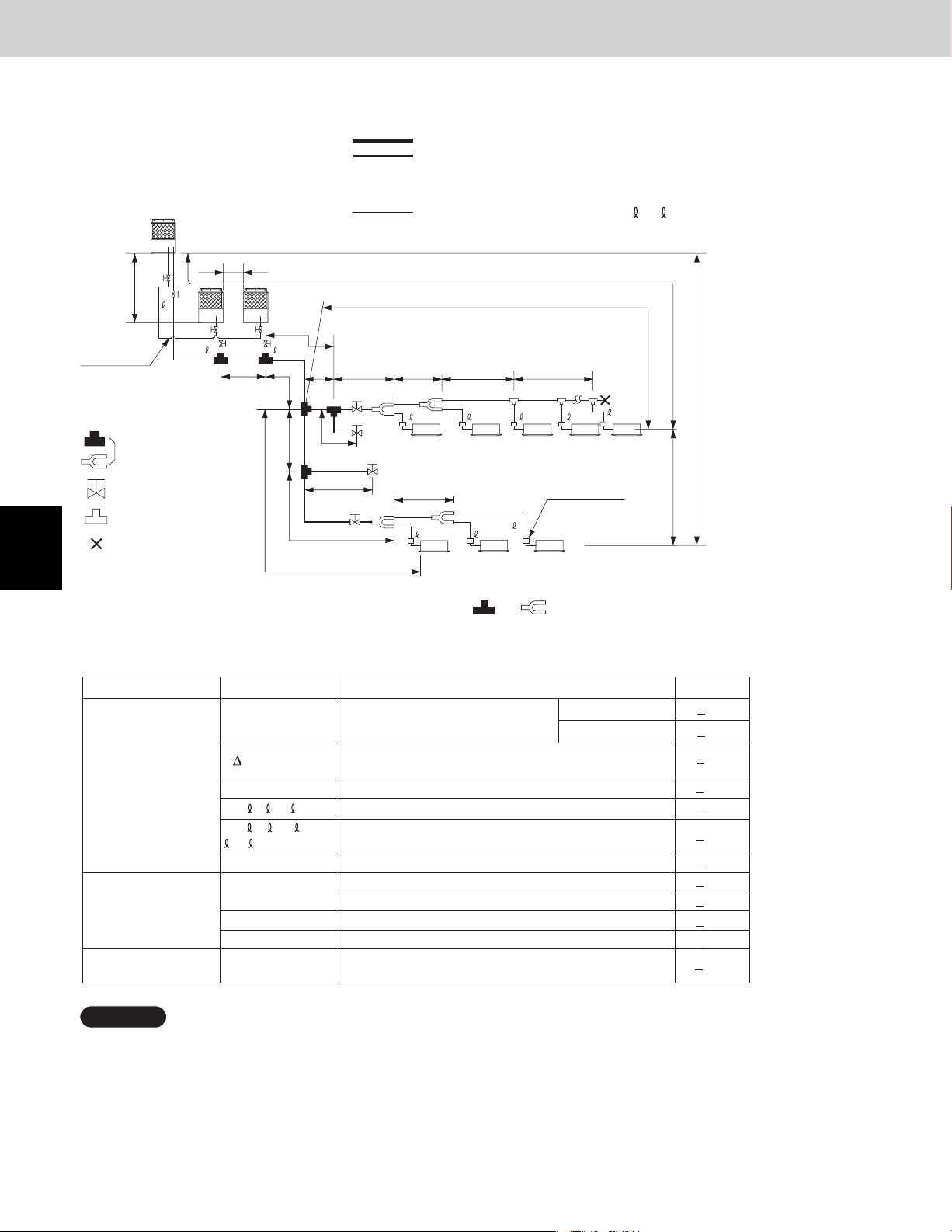
1-3. Tubing Length
Select the installation location so that the length and size of refrigerant tubing are within the allowable range shown
in the figure below.
1.
2. Main distribution tubes LC – LH are selected according to the capacity after the
The outdoor connection main tubing (LO portion) is determined by the total capacity of the
3.
outdoor units that are connected to the tube ends.
4.
Main tubing length LM = LA + LB … < 262 ft
distribution joint.
Sizes of indoor unit connection tubing 1 – 40 are determined by the connection
tubing sizes on the indoor units.
_
1
2
3
4
5
6
7
8
L5
H3
C
LM
Balance tubing
(ø3/8")
Explanation of symbols
Distribution joint
(purchased separately)
Ball valve (field supply)
T-joint (field supply)
Solidly welded shut
(pinch weld)
Note: Do not use commercially available T-joints for the liquid tubing and parts.
Be sure to use special R410A distribution joints (CZ: purchased separately) for outdoor
*
unit connections and tubing branches.
LO
AB
LA
LF
LB LC
Max.1.3 ft
Max.1.3 ft
LG
L4
For
extension
For
extension
LD
4
LH
1
L1
L2
T-joint tubing
(header joint system)
LE L3
5
6
3
2
40
7
Solenoid valve kit
R410A distribution joint
CZ-P900PH1U
CZ-P224BH1U (for indoor unit)
CZ-P680BH1U (for indoor unit)
CZ-P1350BH1U
H1
H2
(for outdoor unit)
(for indoor unit)
Table 2-1 Ranges that Apply to Refrigerant Tubing Lengths and to Differences in Installation Heights
Length (ft.)ContentsMarkItem
<
492
<
574
<
131
<
*2
262ML
<
98
<
984
<
32
<
164
<
131
<
49
<
13
<
6.6
Allowable tubing
length
Allowable elevation
difference
Allowable length of
joint tubing
L = Length, H = Height
L (L2 – L4)
,2...
1
L1+
+
1
A+B
L1
40
2
40
+
...
+LF+LG+LH
L5
H1
H2
H3
L3
Max. tubing length
Difference between max. length and min.
length from the No. 1 distribution joint
Max. length of main tubing (at max. diameter)
Max. length of each distribution tube
Total max. tubing length including length of
each distribution tube (only liquid tubing)
Distance between outdoor units
When outdoor unit is installed higher than indoor unit
When outdoor unit is installed lower than indoor unit
Max. difference between indoor units
Max. difference between outdoor units
T-joint tubing (field-supply); Max. tubing length between
the first T-joint and solidly welded-shut end point
Actual length
Equivalent length
NOTE
1:
The outdoor connection main tubing (LO portion) is determined by the total capacity of the outdoor units that
are connected to the tube ends.
2:
If the longest tubing length (L1) exceeds 295 ft. (equivalent length), increase the sizes of the main tubes (LM)
by 1 rank for the discharge tubes, suction tubes, and narrow tubes. (field supplied)
3:
If the longest main tube length (LM) exceeds 164 feet, increase the main tube size at the portion before 164 ft.
by 1 rank for the suction tubes and discharge tubes. (field supplied)
(For the portion that exceeds 164 feet, set based on the main tube sizes (LA) listed in the table on the following page.)
4: If the tubing length (LA) is less than 16.4 feet, it is recommended that the suction tube be increased by 1 rank.
2 - 4
Page 19

1. Model Selecting and Capacity Calculator
Refrigerant Charge Amount at Shipment (for outdoor unit)
DC
(oz)
Additional Refrigerant Charge
Additional refrigerant charge amount is calculated from the liquid tubing total length as follows.
Amount of Refrigerant Charge Per ft., According to Liquid Tubing Size
(in. (mm))
ø1/4" (ø6.35)
ø3/8" (ø9.52)
ø1/2" (ø12.7)
ø5/8" (ø15.88)
ø3/4" (ø19.05)
ø7/8" (ø22.22)
U-72MF1U9
U-72MF1U9E
416
Liquid tubing size
Amount of refrigerant
charge (oz/ft.)
0.279
0.602
1.38
1.99
2.78
3.93
U-96MF1U9
U-96MF1U9E
416
Required amount of additional refrigerant charge = [(Amount of
additional refrigerant charge per ft. of each size of liquid tube ×
its tube length) + (...) + (...)] + [Necessary amount of additional
refrigerant charge per outdoor unit + (...) + (...)]
* Always charge accurately using a scale for weighing.
Design of 3WAY VRF SYSTEM
1
Table 2-1-1 Necessary Amount of Refrigerant Charge Per Outdoor Unit
Further charge a certain amount listed below in addition to the amount of refrigerant charge.
U-72MF1U9
U-72MF1U9E
42 oz/unit
NOTE
If the tubing length (LA) is less than 16.4 feet, it is necessary to add 71 oz/unit of refrigerant in addition to 42 oz.
System Limitations
Max. capacity allowable connected outdoor units 288,000 BTU/h (24-Ton, 84 kW)
*1: Up to 3 units can be connected if the system has been extended.
U-96MF1U9
U-96MF1U9E
42 oz/unit
*1
3Max. No. allowable connected outdoor units
40Max. connectable indoor units
50 – 130 %Max. allowable indoor/outdoor capacity ratio
2
3
4
5
6
2 - 5
7
8
Page 20
1
Design of 3WAY VRF SYSTEM
1. Model Selecting and Capacity Calculator
1-4. Tubing Size
Table 2-2 Main Tubing Size (LA)
BTU/h
(kW)
Total system tonnage
Combined outdoor
models
Suction tubing
Discharge tubing
Liquid tubing
72,000
(21.1)
ø3/4"
(ø19.05)
ø5/8"
(ø15.88)
96,000
(28.1)
8
ø7/8"
(ø22.22)
ø3/4"
(ø19.05)
ø3/8"
(ø9.52)
139,000
(40.7)
12
U-72MF1U9(E)U-96MF1U9(E)U-72MF1U9(E)
U-72MF1U9(E)
ø1/2"
(ø12.7) (ø15.88)
168,000
(49.2)
14
U-96MF1U9(E)
U-72MF1U9(E)
ø1-1/8"
(ø28.58)
ø7/8"
(ø22.22)
203,000
(59.5)
186
U-72MF1U9(E)
U-72MF1U9(E)
U-72MF1U9(E)
ø5/8"
240,000
(70.3)
20
U-96MF1U9(E)
U-72MF1U9(E)
U-72MF1U9(E)
ø1-1/8"
(ø28.58)
264,000
U-96MF1U9(E)
U-96MF1U9(E)
U-72MF1U9(E)
ø1-3/8"
(ø34.92)
(ø19.05)
*1: If future extension is planned, select the tubing diameter based on the total tonnage after extension.
However extension is not possible if the resulting tubing size is two ranks higher.
*2: The balance tube (outdoor unit tube) diameter is ø3/8" (ø9.52).
*3: Type 1 tubing should be used for the refrigerant tubes.
*4: If the length of the longest tube (L1) exceeds 295 ft. (equivalent length), increase the main tube (LM) size by 1 rank for the
suction, discharge, and liquid tubes. (Use field-supply reducers.) (Select from Table 2-2 and Table 2-7.)
*5: If the longest main tube length (LM) exceeds 164 ft., increase the main tube size at the portion before 164 ft. by 1 rank for
the suction tubes and discharge tubes.
(For the portion that exceeds 164 ft., set based on the main tube sizes (LA) listed in the table above.)
(77.4)
22
ø3/4"
Unit: in. (mm)
288,000
(84.4)
24
U-96MF1U9(E)
U-96MF1U9(E)
U-96MF1U9(E)
2
3
4
5
6
7
8
Size of tubing (LO) between outdoor units
Select the size of tubing between outdoor units based on the main tubing size (LA) as given in the table above.
Table 2-3 Main Tubing Size After Distribution (LB, LC...)
Total capacity
after distribution
Tubing size
Total capacity
after distribution
Tubing size
Below BTU/h
Over BTU/h
Suction tubing
Discharge tubing
Liquid tubing
Below BTU/h
Over BTU/h
Suction tubing
Discharge tubing
Liquid tubing
24.200
(ø15.88) (ø19.05) (ø19.05) (ø22.22)
ø1/2" ø5/8" ø5/8" ø3/4"
ø3/8" ø3/8" ø3/8" ø3/8"
258.000
238.900 258.000
ø1-3/8" ø1-3/8" ø1-3/8"
ø1-1/8" ø1-1/8" ø1-1/8"
(ø19.05) (ø19.05) (ø19.05)
54.600
–
24.200
(ø15.88) (ø19.05) (ø22.22)(ø12.70)
334.400
85.300
54.600
ø3/4"ø3/4"ø5/8"
(ø15.88)
–
334.400
(ø34.92)(ø34.92)(ø34.92)
(ø28.58)(ø28.58)(ø28.58)
ø3/4"ø3/4"ø3/4"
102.400
Table 2-4 Outdoor Unit Tubing Connection Size ( A – D )
BTU/h
(kW)
Suction tubing
Discharge
tubing
Liquid tubing
Balance tubing
72,000
(21.1)
1
*
ø3/4"
*
(ø19.05)
Brazing connection
ø5/8"
(ø15.88)
Brazing connection
ø3/8" (ø9.52)
1
Flare connection
ø3/8" (ø9.52)
Flare connection
96,000
(28.1)
2
*
ø7/8"
*
(ø22.22)
ø3/4"
(ø19.05)
ø3/8" (ø9.52)
Unit: in. (mm)
2
*1
*2
2 - 6
143.300
124.200
(ø28.58)
ø7/8"
ø1/2"
(ø12.70)
85.300
(ø9.52)(ø9.52)(ø9.52)(ø9.52)
124.200
102.400
(ø28.58)
ø3/4"
(ø19.05)
ø1/2"
(ø12.70)
The outdoor unit connection tubing (LO) is
*1:
determined by the total capacity of the outdoor
units connected to the tube ends. The tubing
size is selected based on the table of main
tube sizes after the branch.
If the total capacity of the indoor units con-
*2:
nected to the tube ends is different from the
total capacity of the outdoor units, then the
main tube size is selected based on the total
capacity of the outdoor units.
(For LA, LB, and LF in particular)
If the size of tubing (LA) is less than 16.4 feet,
it is recommended that the tubing diameter be
larger than ø7/8" (ø22.22).
If the size of tubing (LA) is less than 16.4 feet,
it is recommended that the tubing diameter be
larger than ø1-1/8" (ø28.58).
162.400
143.300
(ø28.58)
ø7/8" ø7/8" ø1-1/8"
(ø22.22) (ø22.22)
ø1/2"
200.600
162.400
ø1-1/8"ø1-1/8"ø1-1/8"ø1-1/8"ø7/8"
(ø28.58)
(ø15.88)(ø12.70)
Unit: in. (mm)
238.900
200.600
ø1-1/8"
(ø28.58)
(ø28.58)
ø5/8"ø5/8"
(ø15.88)
Page 21
1. Model Selecting and Capacity Calculator
Table 2-5 Amount of Refrigerant Charge
Liquid tubing size Amount of refrigerant
(in. (mm)) charge (oz/ft.)
ø1/4" (ø6.35) 0.279
ø3/8" (ø9.52) 0.602
ø1/2" (ø12.7) 1.38
ø5/8" (ø15.88) 1.99
ø3/4" (ø19.05) 2.78
ø7/8" (ø22.22) 3.93
Design of 3WAY VRF SYSTEM
Table 2-6 Indoor Unit Tubing Connection Size ( 1– 40 )
Indoor unit type
Distribution
joint-solenoid
valve kit tubing
Solenoid valv
kit-Indoor
unit tubing
connection
*1: For the solenoid valve kits, use type 160 with parallel specifications. Branch the tubing before and after the solenoid valve kits.
Table 2-7 Refrigerant tubing (Existing tubing can be used.)
ø1/4" (ø6.35) t1/32 (t0.8)
ø3/8" (ø9.52) t1/32 (t0.8) ø1-1/8" (ø28.58) t5/128 (t1.0)
ø1/2" (ø12.7) t1/32 (t0.8)
ø5/8" (ø15.88) t5/128 (t1.0)
ø3/4" (ø19.05)
Suction tubing
Discharge tubing
Liquid tubing
e
Gas tubing
Liquid tubing
Material O Material 1/2H • H
over t5/128 (t1.0)
7
Tubing size (in. (mm))
9
ø7/8" (ø22.22) t5/128 (t1.0)
ø1-3/8" (ø34.92)
ø1-5/8" (ø41.28)
12 15 18 19 24 36 48 54
ø5/8" (ø15.88)
ø1/2" (ø12.7)
ø3/8" (ø9.52)
ø1/2" (ø12.7)
ø1/4" (ø6.35)
over t3/64 (t1.20)
t3/64 (t1.1)
*
When bending the tubes, use a bending
radius that is at least 4 times the outer
diameter of the tubes.
In addition, take sufficient care to avoid
crushing or damaging the tubes when
bending them.
ø5/8" (ø15.88)
ø3/8" (ø9.52)
Unit: in. (mm)
1
2
3
4
2 - 7
5
6
7
8
Page 22
1. Model Selecting and Capacity Calculator
1-5. Installation Standards
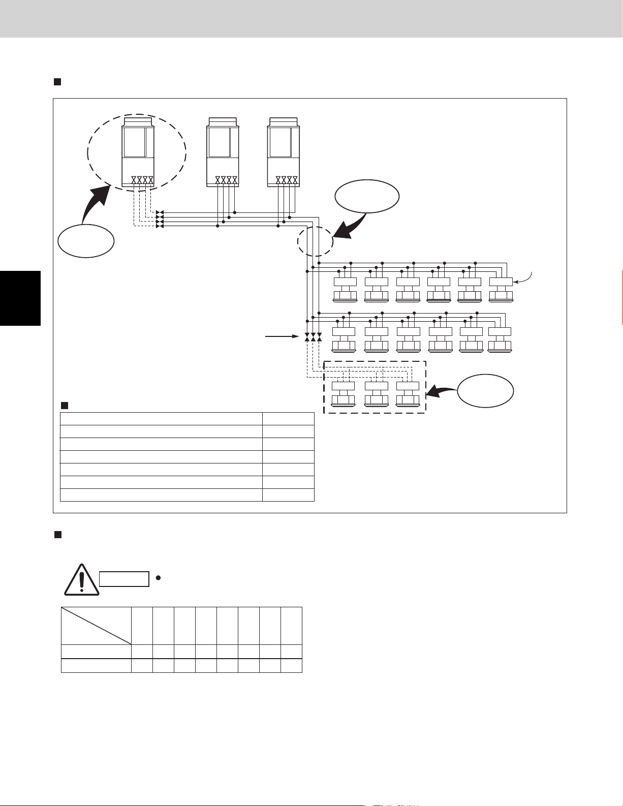
Relationship between A/C units and refrigerant tubing
Design of 3WAY VRF SYSTEM
1
2
3
Room
Indoor unit
Hallway
Solenoid
valve kit
Liquid
Room
Indoor unit
Gas tube
tube
Solenoid
valve kit
Outdoor unit Outdoor unit Indoor unit
Install the solenoid valve kit 98 ft. or less from the indoor unit.
In quiet locations such as hospitals, libraries, and hotel rooms, the refrigerant noise may be somewhat noticeable. It is recom-
mended that the solenoid valve kit be installed inside the corridor ceiling, at a location outside the room.
Hallway
Common solenoid valve kit
Multiple indoor units under group control can utilize a solenoid valve kit in common.
Categories of connected indoor unit capacities are determined by the solenoid valve kit.
Type of solenoid valve kit Total capacity of indoor units (BTU/h)
160 19.000 < Total capacity
56 7.500
If the capacity range is exceeded, use 2 solenoid valves connected in parallel.
4-tube layout 3-tube layout 2-tube layout
Suction tube
Discharge tube
Liquid tube
Solenoid
valve kit
54.600
Room
Indoor unit
Suction tube
Discharge tube
Liquid tube
Balance tube
Desirable Undesirable
Room
Indoor unit
Total capacity 19.000
(2) When adding ball valve for outdoor unit
1. Location: Install the ball valve at the main tube of the distribution joint.
4
5
6
7
8
Outdoor unit
for extension
Ball valve (for extension)
(Planned expansion)
Main tube of distribution joint
Balance tube
Discharge tube
Less than 1.3 ft
Distribution joint
(Suction tube)
Main tube
Liquid tube
To indoor unit
2. Installation requirements
• Be sure to install the ball valve up-grade to prevent the inadvertent flow of oil.
• Install the ball valve at the shortest distance (within 1.3 ft.) from the main tube. If the diameter of the ball valve
is smaller than that of the main tube, use a reducer or the like to reduce the size of the tubing at that location.
NOTE
• If the ball valve is installed at the outdoor unit (including extension for outdoor unit), face the service port of
the valve toward the outdoor unit side (see above illustration; dotted line) and allow a distance of over 1.6 ft
from the outdoor unit. If the ball valve is installed between the indoor unit (including extension for indoor unit)
and the main tube, face the ball valve toward the indoor unit side (see above illustration; dotted line).
• Use a field supply ball valve.
2 - 8
Page 23

Design of 3WAY VRF SYSTEM
1. Model Selecting and Capacity Calculator
1-6. Straight Equivalent Length of Joints
Design the tubing system by referring to the following table for the straight equivalent length of joints.
Table 2-8 Straight Equivalent Length of Joints
Gas tubing size (in.(mm))
90° elbow
45° elbow
U-shape tube bent
(R2–23/64–3–15/16 in.)
T r ap bend
Y-branch distr ibution joint Equivalent length conversion not needed.
Ball v alve f or ser vice Equivalent length conversion not needed.
1/2"
(12.7)
0.8 0.9 1
7.5 9.2 10.5 15.4
5/8"
(15.88)
1 1.1 1.4 1.9 2.5 2.8
3 3.4 4.1 5.6 7.4 8.4
3/4"
(19.05)
1.6
1.2
4.7
1-1/8"
(28.58)
1.4
7/8"
(22.22)
12.5 19.2 22.3
1-3/8"
(34.92)
1.8 2.0
Unit: ft.
1-5/8"
(41.28)
1
2
3
4
5
6
7
2 - 9
8
Page 24
1. Model Selecting and Capacity Calculator
Check of limit density
Design of 3WAY VRF SYSTEM
1
2
WARNING
1-7. Check of limit density
When installing an air conditioner in a room, it is necessary to ensure that if the refrigerant gas accidentally
leaks out, its density does not exceed the limit level for
that room.
CAUTION
Always check the gas density limit for the room in
which the unit is installed.
Pay special attention to any
location, such as a basement,
etc., where leaking refrigerant
can accumulate, since refrigerant gas is heavier than air.
3
4
5
6
7
8
2 - 10
Page 25

Design of 3WAY VRF SYSTEM
1. Model Selecting and Capacity Calculator
1-8. Calculation of Actual Capacity of Indoor Unit
Calculating the actual capacity of each indoor unit
Because the capacity of a multi air-conditioner changes according to the temperature conditions, tubing length, elevation difference and other factors, select the correct model after taking into account the various correction values. When selecting The
model, calculate the corrected capacities of the outdoor unit and each indoor unit. Use the corrected outdoor unit capacity and
the total corrected capacity of all the indoor units to calculate the actual final capacity of each indoor unit.
1. Outdoor unit capacity correction coefficient
Find the outdoor unit capacity correction coefficient for the following items.
(1) Capacity correction for the outdoor unit model
The capacity correction coefficient is 1.00.
(2)
Capacity correction for the outdoor unit temperature conditions
Cooling:
Heating:
(3) Capacity correction for the outdoor unit tubing length and elevation difference
From the graph of capacity change characteristics on page 2-14, use the tubing length and elevation difference to find the
capacity correction coefficient.
The outdoor unit correction coefficient is the value which corresponds to the most demanding indoor unit.
(4) Capacity correction for outdoor unit frosting/defrosting during heating
From the table on page 2-13, find the capacity correction coefficient.
From the graph of capacity characteristics on page 2-13 ( Graph of Outdoor Unit Capacity Characteristics),
use the outdoor temperature to find the capacity correction coefficient.
From the graph of capacity characteristics on page 2-15, use the outdoor temperature to find the capacity
correction coefficient.
* Indoor air intake temperature should be set to 68 °FDB.
1
2. Indoor unit capacity correction coefficients
Find the indoor unit capacity correction coefficient for the following items.
(2) Capacity correction for the indoor unit temperature conditions
From the graph of capacity characteristics on page 2-14 ( Graph of Indoor Unit Capacity Characteristics), use the indoor
temperature to find the capacity correction coefficient.
(3) Capacity distribution ratio based on the indoor unit tubing length and elevation difference
First, in the same way as for the outdoor unit, use the tubing length and elevation difference for each indoor unit to find the
correction coefficient from the graph of capacity change characteristics on page 2-14. Then divide the result by the outdoor
unit correction coefficient to find the capacity distribution ratio for each indoor unit.
Capacity distribution ratio for each indoor unit (3) = Correction coefficient for that indoor unit / Correction coefficient for the outdoor unit
3. Calculating the corrected capacities for the outdoor unit and each indoor unit
The corrected capacities for the outdoor unit and each indoor unit are calculated form the formula below.
<Cooling>
Outdoor unit corrected cooling capacity (5) = Outdoor unit rated cooling capacity × Correction coefficient for model ((1)
Page 2-11) × Correction coefficient for outdoor temperature conditions ((2)
Page 2-13) × Correction coefficient for tubing length and elevation difference
((3) Page 2-14)
* However, if the outdoor unit corrected cooling capacity [5] is greater than 100%, then the outdoor unit corrected cooling
capacity [5] is considered to be 100%.
Corrected cooling capacity of each indoor unit (5) = Rated cooling capacity for that indoor unit × Correction coefficient for
indoor temperature conditions at that indoor unit ((2) Page 2-14) × Distribution ratio based on tubing length and elevation difference at that indoor unit ((3) Page 2-14)
However, the corrected cooling capacity of each indoor unit is found as shown below.
If (2) < 100% and (2) × (3) > 100%: Corrected cooling capacity for that indoor unit [5] = Rated cooling capacity for that indoor unit
If (2) >100%: Corrected cooling capacity for that indoor unit (5) = Rated cooling capacity for that indoor unit × (2)
2
3
4
5
6
7
2 - 11
8
Page 26

Design of 3WAY VRF SYSTEM
1. Model Selecting and Capacity Calculator
<Heating>
Outdoor unit corrected heating capacity (5) = Outdoor unit rated heating capacity × Correction coeffi cient for model ((1)
Page 2-11) × Correction coeffi cient for outdoor temperature conditions ((2)
Page 2-15) × Correction coeffi cient for tubing length and elevation difference
((3) Page 2-14) × Correction coeffi cient for frosting/defrosting ((4) Page
* However, if the outdoor unit corrected heating capacity [5] is greater than 100%, then the outdoor unit corrected heating
capacity is considered to be 100%.
Corrected heating capacity of each indoor unit (5) = Rated heating capacity for that indoor unit × Correction coeffi cient for
indoor temperature conditions at that indoor unit ((2) Page 2-14) × Distribution ratio based on tubing length and elevation
difference at that indoor unit.
However, the corrected heating capacity of each indoor unit is found as shown below.
If (2) < 100% and (2)
100%: Corrected heating capacity for that indoor unit (5) = Rated heating capacity for that indoor unit × (2)
If (2)
* Characteristic graphs are shown on the pages listed above next to each correction item. Find each correction coeffi cient
from the appropriate conditions.
× (3) > 100%: Corrected heating capacity for that indoor unit (5) = Rated heating capacity for that indoor unit
2-13)
1
2
3
4
5
6
7
4. Calculating the actual indoor unit capacity based on the indoor/outdoor corrected capacity ratio
Calculate the actual capacity of each indoor unit from the values (found in (3)) for the corrected outdoor unit capacity and the
corrected capacity of each indoor unit.
<Cooling capacity>
Corrected indoor/outdoor capacity ratio during cooling (Ruc) = Total corrected cooling capacity of all indoor units in that system /
Corrected outdoor unit cooling capacity
If the corrected outdoor unit cooling capacity is greater than or equal to the total corrected unit cooling capacity of all indoor units
in that system (Ruc
Actual cooling capacity of each indoor unit (7) = Corrected cooling capacity of each indoor unit (5) (In other words, the correction coeffi cient (6), based on the corrected indoor/outdoor capacity ratios for each indoor unit, is 1.)
If the corrected outdoor unit cooling capacity is less than the total corrected unit cooling capacity of all indoor units in that system (Ruc > 1), then:
(Actual cooling capacity of each indoor unit (7)) = (Corrected cooling capacity of each indoor unit (5)) × (0.25 × Ruc + 0.75)
/ Ruc
(In other words, the correction coeffi cient (6), based on the corrected indoor/outdoor capacity ratios for each indoor unit, is
the underlined part in the formula above.)
<Heating capacity>
Corrected indoor/outdoor capacity ratio during heating (Ruh) = Total corrected heating capacity of all indoor units in that system
/ Corrected outdoor unit heating capacity
If the corrected outdoor unit heating capacity is greater than or equal to the total corrected unit heating capacity of all indoor
units in that system (Ruh
Actual heating capacity of each indoor unit (7) = Corrected heating capacity of each indoor unit (5)
(In other words, the correction coeffi cient (6), based on the corrected indoor/outdoor capacity ratios for each indoor unit, is 1.)
If the corrected outdoor unit heating capacity is less than the total corrected unit heating capacity of all indoor units in that system (Ruh > 1), then:
(Actual heating capacity of each indoor unit (7)) = (Corrected heating capacity of each indoor unit (5)) × (0.1 × Ruh + 0.9) /
Ruh
(In other words, the correction coeffi cient (6), based on the corrected indoor/outdoor capacity ratios for each indoor unit, is
the underlined part in the formula above.)
1), then:
1), then:
8
2 - 12
Page 27
Design of 3WAY VRF SYSTEM
1. Model Selecting and Capacity Calculator
Refer to the graph below for the correction coeffi cients for Ruc and Ruh.
Indoor unit capacity correction coefficient for Ruc (cooling)
Indoor unit capacity correction coefficient for Ruh (heating)
1.0
0.9
0.8
0.7
0.6
0.5
Indoor unit capacity correction coefficient
0.4 0.5 0.6 0.7 0.8 0.9 1.0 1.1 1.2 1.3 1.4 1.5 1.6 1.7 1.8 1.9
Corrected indoor/outdoor capacity ratio (Ruc or Ruh)
NOTE
When Ruc or Ruh is less than or equal to 1.0, the indoor unit capacity correction coefficient for both Ruc and Ruh is 1.0.
2.0
1
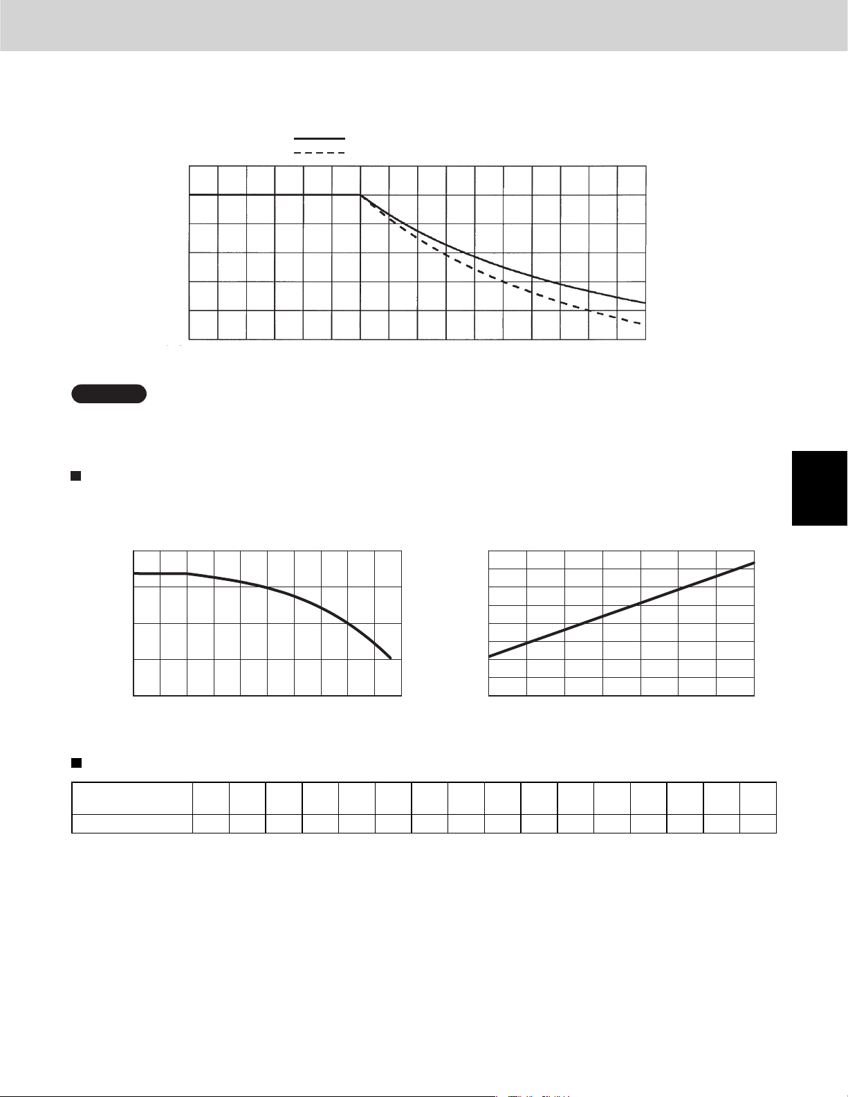
5. Graph of capacity correction coefficients
Graph of outdoor unit capacity characteristics (1 – (2))
Outdoor unit cooling capacity characteristics
120
110
100
90
80
Rate of cooling capacity change (%)
23 32 41 50 59 68 77 86 95 104 113
Outdoor air intake temp. (°F DB) Outdoor air intake temp. (°F WB)
Outdoor unit heating capacity correction coeffi cient during frosting/defrosting (1 – (4))
Outdoor intake air
(°FWB RH85%)
temp.
Correction coefficient 0.97 0.97 0.97 0.96 0.94 0.91 0.89 0.87 0.87 0.87 0.88 0.89 0.91 0.92 0.95 1.0
* To calculate the heating capacity with consideration for frosting/defrosting operation, multiply the heating capacity found
from the capacity graph by the correction coeffi cient from the table above.
–4 5 1417212324283032333537394142
Outdoor unit heating capacity characteristics
120
110
100
90
80
70
60
50
40
Rate of heating capacity change (%)
-4 5 142332415059
2
3
4
5
6
2 - 13
7
8
Page 28
1. Model Selecting and Capacity Calculator
Graph of indoor unit capacity characteristics (2 – (2))
Indoor unit cooling capacity characteristics Indoor unit heating capacity characteristics
Design of 3WAY VRF SYSTEM
1
2
3
4
120
110
100
90
80
57 59 60 62 64 66 68 69 71 73 75 77 59 60 62 64 66 68 69 71 73 75 77 78
Indoor air intake temp. ( °F WB)
Rate of cooling capacity change (%)
indicates the rating point. indicates the rating point.
110
105
100
95
90
Indoor air intake temp. ( °F DB)
Rate of heating capacity change (%)
80
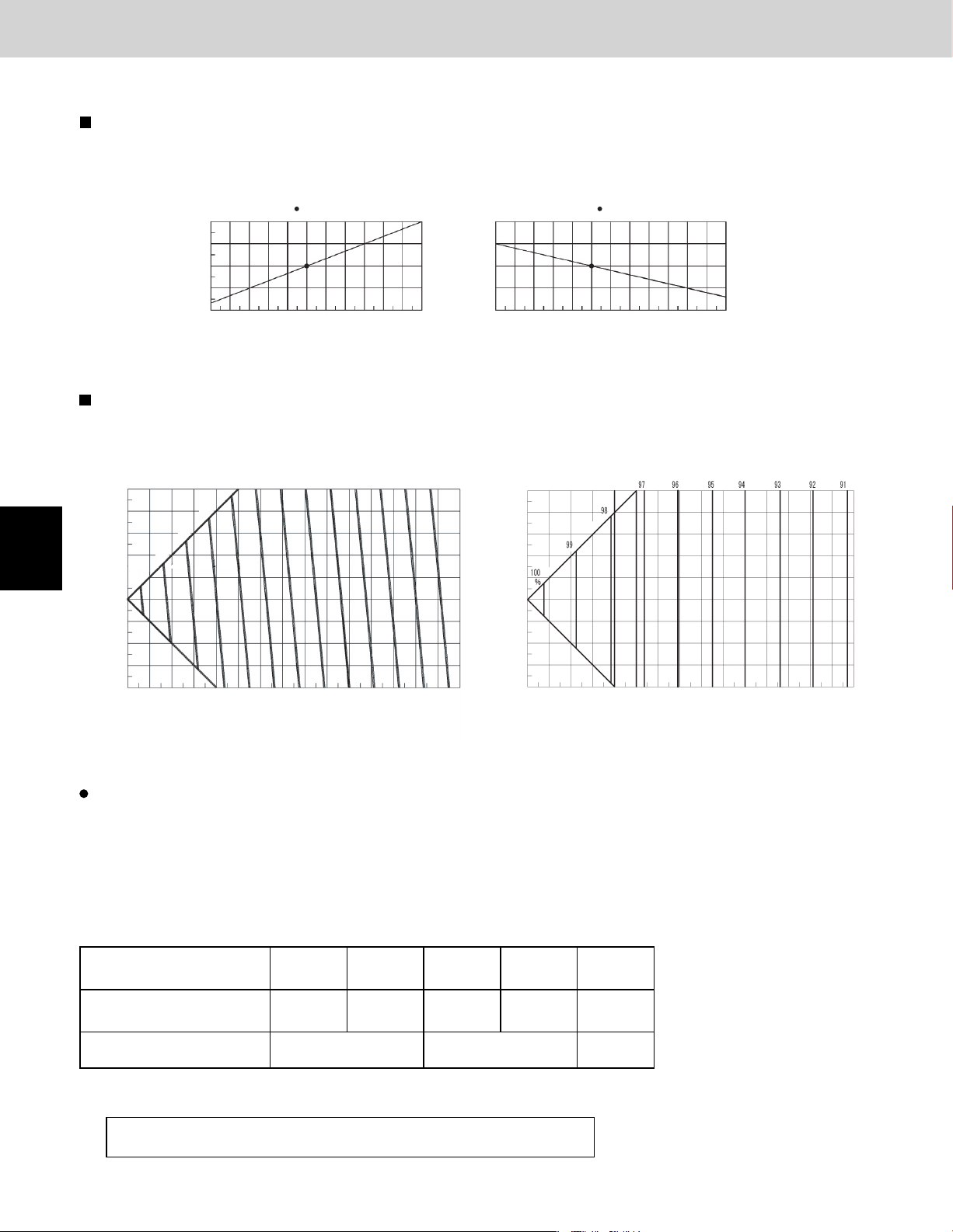
Graph of capacity change characteristics resulting from tubing length and elevation difference (1 / 2 – (3))
<Cooling>
Base capacity
change rate
164
131
98
66
100
33
%
0
-33
Elevation difference (ft)
-66
-98
-131
0 98 66 33 131 164 197 230 262 295 328 361 394 427 459 492
96
98
92 90 88 86 84 82 80 78 76
94
*1
Equiv
alent length (ft)
The positive side for the elevation difference indicates that the outdoor unit is installed at a higher position than the indoor units.
The negative side indicates the opposite.
<Heating>
Base capacity
change rate
164
131
98
66
33
0
-33
Elevation difference (ft)
-66
-98
-131
0 98 66 33 131 164 197 230 262 295 328 361 394 427 459 492
Equivalent length (ft)
5
6
7
8
The capacity loss that is caused by the tubing length can be reduced by increasing the sizes of the discharge tubes and suc-
tion tubes. Refer to Table 2-9 and make the appropriate changes. However be sure that the total length does not exceed the
maximum.
* The only sizes which can be increased are the LM (main tube with the largest diameter) gas tubes, and the changes are
limited to those shown in Table 2-9.
In addition, note that the additional refrigerant charge is determined only by the narrow-tube size.
Table 2-9 Equivalent Length Correction Coeffi cient when the Size of the Discharge Tubes and Suction Tubes (LM)
is Increased
Standard tubing diameter
(gas tube, in.(mm))
Tubing diameter after change
(gas tube,in.(mm))
Equivalent length correction
coefficient
ø1/2"
(ø12.7)
ø5/8" ø3/4" ø7/8" ø1-1/8" ø1-3/8"
(ø15.88) (ø19.05) (ø22.22) (ø28.58) (ø34.92)
ø5/8"
(ø15.88) (ø19.05) (ø22.22) (ø28.58)
0.4 0.5 0.6
ø3/4" ø7/8" ø1-1/8"
* If the size of the discharge tubes and suction tubes (LM) have been increased, apply the correction coeffi cient from Table
2-9 and calculate the equivalent length of the LM section.
Equivalent length of tubing after size increase
= Standard tubing equivalent length × Equivalent length correction coeffi cient
2 - 14
Page 29
Design of 3WAY VRF SYSTEM
1. Model Selecting and Capacity Calculator
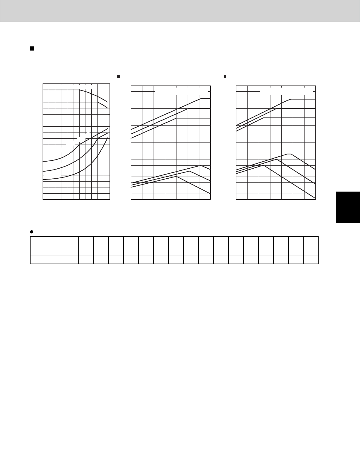
1-9. Capacity Correction Graph According to Temperature Condition
Capacity characteristics
(The corrected capacity for specifi c temperature conditions can be found from the graphs below.)
< Cooling > < Heating >
6-Ton 8-Ton
130
Indoor air intake temp. (WB) = 71 FIndoor air intake temp. (WB) = 71 F
Indoor air intake temp. (WB) = 72°F
120
110
WB = 67°F
100
90
WB = 61°F
80
Capacity ratio (%)
120
110
100
90
80
70
Indoor air intake temp. (WB) = 72°F
60
WB = 67°F
50
40
WB = 61°F
Input ratio (%)
30
20
10
14 23 32 41 50 59 68 77 86 95
104 113
130
120
110 110
100
90
80
70
60
Capacity ratio (%)
50
40
130
120
100
90
Input ratio (%)
80
70
60
50
- 4
Indoor air intake temp. (°F DB)
61
70
79
61
70
79
5 142332415059
130
120
100
90
80
70
60
Capacity ratio (%)
50
40
130
120
110110
100
90
Input ratio (%)
80
70
60
50
- 4
5 142332415059
Indoor air intake temp. (°F DB)
61
70
79
61
1
70
79
2
Heating capacity correction coeffi cients for frost/defrost operation
Outdoor intake air
temp.
–4 5 1417212324283032333537394142
(°F WB RH85%)
Correction coefficient 0.97 0.97 0.97 0.96 0.94 0.91 0.89 0.87 0.87 0.87 0.88 0.89 0.91 0.92 0.95 1.0
* The heating capacity when frost/defrost operation is considered is calculated by multiplying the heating capacity found
from the capacity graph by the correction coeffi cient from the table above.
3
4
5
6
7
2 - 15
8
Page 30
1
2
3
Design of 3WAY VRF SYSTEM
1. Model Selecting and Capacity Calculator
Rated performance values
Item Cooling Heating
Cooling capacity
Type
72 72,000(21.1) 5.30 81,000(23.7) 5.79
96 96,000(28.1) 7.75 108,000(31.6) 8.6
BTU/h(kW)
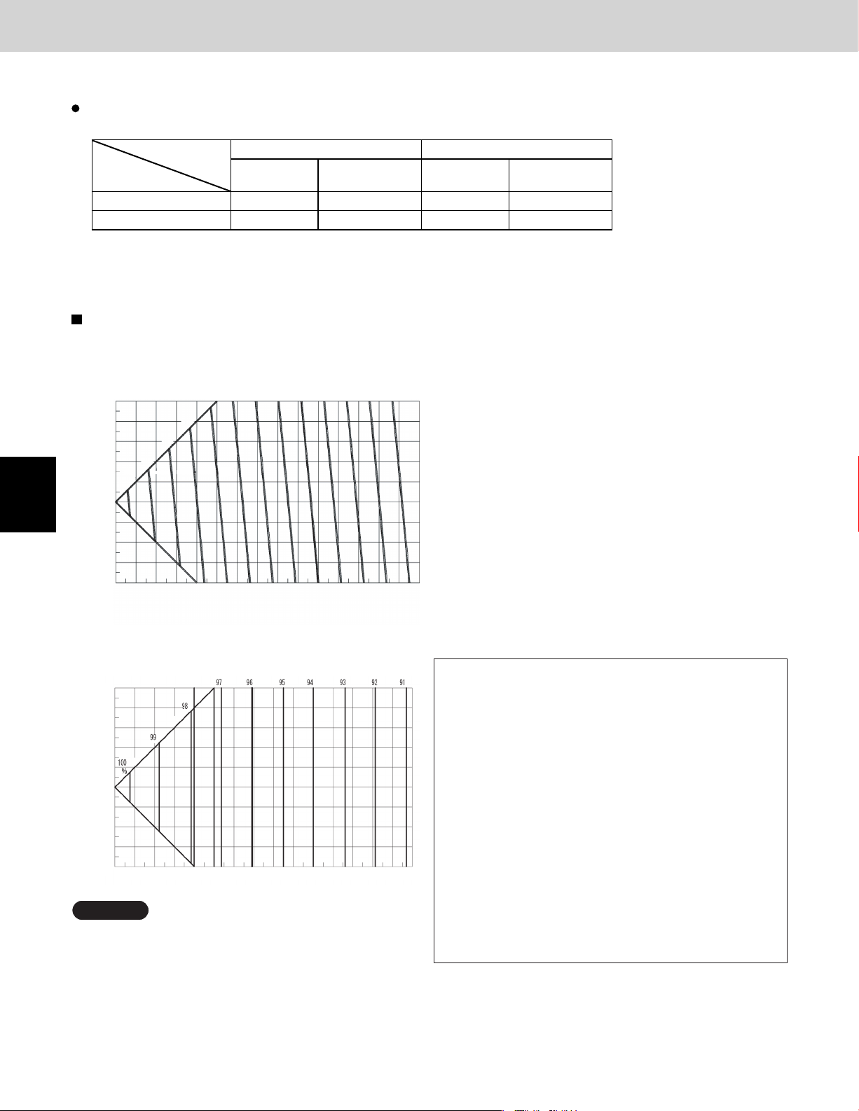
1-10. Capacity Correction Graph According to Tubing Length and Elevation Difference
Capacity change characteristics
<Cooling>
Base capacity
change rate
164
131
98
66
100
33
%
0
–33
Elevation difference (ft)
–66
–98
–131
0 33 66 98 131 164 197 230 262 295 328 361 394 427 459 4920 33 66 98 131 164 197 230 262 295 328 361 394 427 459 492
96
98
92 90 88 86 84 82 80 78 76
94
*1
Equivalent length (ft)
Power consumptionkWHeating capacity
BTU/h(kW)
Power consumption
kW
4
5
6
7
8
<Heating>
Base capacity
change rate
164
131
98
66
33
0
–33
–66
Elevation difference (ft)
–98
–131
0 33 66 98 131 164 197 230 262 295 328 361 394 427 459 492
Equivalent length (ft)
NOTE
The positive side for the elevation difference indicates that
the outdoor unit is installed at a higher position than the
indoor units. The negative side indicates the opposite.
*1 Sample calculations
(System: 8 Ton, 164ft equivalent length, 49ft elevation
difference
The cooling capacity and heating capacity for this system are
found as shown below.)
●
Cooling operation
From the graph, the base capacity change rate is found to be
92.0%.
×
96,000 BTU/h
(28.1kW
●
Heating operation
From the graph, the base capacity change rate is found to be
97.2%.
Because the calculation result exceeds 97.2%, the capacity
change rate is 97.2%.
(31.6kW
×
92.0% = 88,320 BTU/h
92.0% = 25.8kW)
×
97.2% = 105,000 BTU/h108,000 BTU/h
×
97.2% = 30.7kW) Heating capacity is
Capacity change rate is 92.0%.
Cooling capacity is
88,320 BTU/h (28.1 kW)
105,000 BTU/h (30.7 kW)
2 - 16
Page 31

Design of 3WAY VRF SYSTEM
1. Model Selecting and Capacity Calculator
If the maximum tubing length (L1) exceeds 295 ft (equivalent length), increase the tubing size of the main liquid, gas tubes(LM)
by one rank.
ø
However, the upper limit for the gas tube size is
Increasing the tubing size of the gas tubes can reduce the loss of capacity caused by longer tubing lengths.
Refer to Table 2-11 to increase the tubing size. However, the maximum allowable tubing length must not be exceeded.
* The amount of additional refrigerant charge is determined from the liquid tube size only.
Table 2-10 Correction coefficient for equivalent length when the size of the gas tube (LM) is increased
Standard tube diameter
(gas tube, in.(mm))
Tube diameter after change
(gas tube, in.(mm))
Equivalent length correction
coefficient
* When increasing the size of the suction and discharge tubing (LM), multiply by the
correction coefficient from Table 2-11 and calculate the equivalent length for section LM.
Tubing equivalent length after size increase
= Standard tubing equivalent length × Equivalent length correction coefficient
ø1/2"
(ø12.7)
ø5/8"
(ø15.88)
ø5/8"
(ø15.88)
ø3/4"
(ø19.05)
0.4 0.5 0.6
1-3/8".
ø3/4"
(ø19.05)
ø7/8"
(ø22.22)
ø7/8"
(ø22.22)
ø1-1/8"
(ø28.58)
ø1-1/8"
(ø28.58)
ø1-3/8"
(ø34.92)
1
Table 2-11 Dimensions for connections of each part Unit: in.
Position A B C D E F G H I J
Dimension ø1-1/2" ø1-1/4" ø1-1/8" ø1" ø7/8" ø3/4" ø5/8" ø1/2" ø3/8" −
2
3
4
5
6
2 - 17
7
8
Page 32

Design of 3WAY VRF SYSTEM
2. System Design
2-1. System Example
(1) Below are the tables created using the “PAC System Diagram Software.” Details of the calculations are shown in (2).
As the maximum tubing length (equivalent length) is over 295ft. in the following selection sample, the item (3) is applied due
to the main tube size up.
Outdoor
unit 1
Outdoor
unit 2
1
2
3
4
5
170 ft
Elevation
difference: 33 ft
33 ft 33 ft 66 ft
33 ft 33 ft 33 ft
Indoor
unit 1
Indoor
unit 2
Selection conditions
Outdoor unit
Cooling
Heating
Actual tubing length
Equivalent length (with consideration for curves, etc.)
[* Equivalent length after size-up correction]
* Equivalent length after size-up correction is used for the calculation of actual capacity.
Air condition (DB/WB)
Max. load (BTU/h)
Air condition (DB/WB)
Max. load (BTU/h)
91.0 / 72.0 78.0 / 64.0
37.0 / 35.0 69.0 / 55.0 69.0 / 55.0
367.2 ft
[285.6 ft]
Room 1
(indoor unit 1)
50,000
52,000
306 ft 205 ft
246 ft
[164.4 ft]
Preliminary selection
Outdoor unit
Selected model
Load (cooling/heating) (BTU/h)
Rated capacity (cooling/heating) (BTU/h)
(5) Corrected capacity (cooling/heating) (BTU/h)
(7) Actual capacity (cooling/heating) (BTU/h)
Total corrected capacity of indoor units (cooling/heating) = 126,915 / 143,254
Ruc = 126,915 / 125,752 = 1.009 > 1 Ruh = 143,254 / 120,304 = 1.191 > 1
Type
72 + 72
139,000 /
157,000
125,752 /
120,304
Room 1
(indoor unit 1)
Type 54
50,000 /
52,000
54,600 /
61,400
54,600 /
61,768
52,223 / 35,595 / 18,344 / 17,876 /
Indoor
unit 3
Room 2
(indoor unit 2)
78.0 / 64.0
32,000
33,000
238 ft
285.6 ft
[204 ft]
Room 2
(indoor unit 2)
Type 36
32,000 /
33,000 19,000
36,000 /
39,000
35,842 /
39,234
Room 3
(indoor unit 3)
Room 3
(indoor unit 3)
Solenoid valve kit
Indoor
unit 4
Room 4
(indoor unit 4)
78.0 / 64.0
18,000
69.0 / 55.0
19,000
271 ft
325.2 ft
[243.6 ft]
Type 18 Type 18
18,000 /
19,000 /
21,000
21,126
78.0 / 64.0
17,900
69.0 / 55.0
21,500
306 ft
367.2 ft
[285.6 ft]
Room 4
(indoor unit 4)
17,900 /
21,500
19,000 /
21,000
18,000 /18,472 /
21,126
18,07918,07933,57652,861
6
7
8
Outdoor unit changes
The corrected outdoor unit capacity is less than the total corrected capacity of all indoor units in the system. As a result, the actual capacity of
each indoor unit is less than the maximum load. Therefore the outdoor unit is increased by one rank.
Outdoor unit
Selected model Type 54
Load (cooling/heating) (BTU/h)
Rated capacity (cooling/heating) (BTU/h)
(5) Corrected capacity (cooling/heating) (BTU/h)
(7) Actual capacity (cooling/heating) (BTU/h)
Total corrected capacity of indoor units (cooling/heating) = 126,915 / 143,254
Ruh = 143,254 / 146,242 = 0.980 < 1Ruc = 126,915 / 146,710 = 0.865 < 1
Type
96 + 72
168,000 / 54,600 / 36,000 / 19,000 / 19,000 /
189,000
146,710 / 54,600 / 35,842 / 18,472 / 18,000 /
146,242 61,768
Room 1
(indoor unit 1)
50,000 /
52,000 33,000 19,000 21,500
61,400 39,000 21,000 21,000
2 - 18
Room 2
(indoor unit 2)
Type 36 Type 18 Type 18
32,000 / 18,000 / 17,900 /
39,00061,400
Room 3
(indoor unit 3)
21,12639,234
Room 4
(indoor unit 4)
21,126
18,000 /18,472 /35,842 /54,600 /
21,00021,000
Page 33

Design of 3WAY VRF SYSTEM
2. System Design
Indoor unit changes
The indoor unit in room 4, where the corrected indoor unit capacity is less than the maximum load, is increased by one rank.
Outdoor unit
Selected model
Load (cooling/heating) (BTU/h)
Rated capacity (cooling/heating) (BTU/h)
(5) Corrected capacity (cooling/heating) (BTU/h)
(7) Actual capacity (cooling/heating) (BTU/h)
Total corrected capacity of indoor units (cooling/heating) = 132,600 / 149,290
Ruh = 149,290 / 146,242 = 1.021 > 1Ruc = 132,600 / 146,710 = 0.904 < 1
For both cooling and heating in all rooms, actual capacity is now greater than or equal to the maximum load. Selection is completed.
Type
96 + 72
168,000 /
189,000
146,710 /
146,242
Room 1
(indoor unit 1)
Type 54 Type 36 Type 18 Type 24
50,000 /
52,000
54,600 /
61,400
54,600 /
61,768
54,600 /
60,631
(2) Calculate the final selection results according to the capacity calculation procedure.
Room 2
(indoor unit 2)
32,000 /
33,000
36,000 /
39,000
35,842 /
39,234
35,842 /
38,512
Room 3
(indoor unit 3)
18,000 /
19,000
19,000 /
21,000
18,472 /
21,126
18,472 /
20,737
Room 4
(indoor unit 4)
17,900 /
21,500
25,000 /
27,000
23,685 /
27,162
23,684 /
26,662
[From calculation of the correction coefficient to calculation of actual capacity]
Selected model
Load (cooling/heating) (BTU/h)
Rated capacity (cooling/heating) (BTU/h)
Model
(1)
(2) Temp. condition
(3) Tubing length, elevation difference
Distribution ratio
Correction coefficient
(4) Frosting/defrosting
Result of (2) × (3)
Correction coefficient applied to indoor unit *1
(5) Corrected capacity (BTU/h) *2
(6) Correction coefficient for corrected capacity ratio
(7) Actual capacity (BTU/h)
Outdoor unit
Type
96 + 72
168,000 /
189,000
1.0000 /
1.0000
1.0203 /
0.9688
0.8559 /
0.8974
0.8900
146,710 /
146,242
Room 1
(indoor unit 1)
Type 54 Type 36 Type 18 Type 24
50,000 /
52,000
54,600 /
61,400
0.9474 /
1.0060
0.9205 /
0.9436
1.0755 /
1.0515
1.0189 /
1.0578
1.0000 /
1.0000
54,600 /
61,768
1.0000 /
0.9816
54,600 /
60,631
Room 2
(indoor unit 2)
32,000 /
33,000
36,000 /
39,000
0.9474 /
1.0060
0.8995 /
0.9285
1.0509 /
1.0346
0.9956 /
1.0408
0.9956 /
1.0000
35,842 /
39,234
1.0000 /
0.9816
35,842 /
38,512
(Cooling/heating)
Room 3
(indoor unit 3)
18,000 /
19,000
19,000 /
21,000
0.9474 /
1.0060
0.8783 /
0.9134
1.0262 /
1.0178
0.9722 /
1.0239
0.9722 /
1.0000
18,472 /
21,126
1.0000 /
0.9816
18,472 /
20,737
Room 4
(indoor unit 4)
17,900 /
21,500
25,000 /
27,000
0.9474 /
1.0060
0.8559 /
0.8974
1.0000 /
1.0000
0.9474 /
1.0060
0.9474 /
1.0000
23,685 /
27,162
1.0000 /
0.9816
23,684 /
26,662
1
2
3
4
5
6
*1: This varies depending on the values of (2) and (2) × (Distribution ratio in (3)).
*2: Corrected outdoor unit capacity = Rated outdoor unit capacity × (1) × (2) × (3) × (4)
The actual capacity is calculated as shown below.
Cooling: Ruc = (54,600 + 35,842 + 18,472 + 23,684) / 146,710 = 0.904 < 1
Therefore,
Actual cooling capacity of each indoor unit = Corrected cooling capacity of each indoor unit
(In other words, the correction coefficient (6) for the corrected capacity ratio is 1.)
Heating: Ruh = (60,631 + 38,512 + 20,737 + 26,662) / 146,242 = 1.021 > 1
2 - 19
7
8
Page 34

Design of 3WAY VRF SYSTEM
2. System Design
(3) Increasing the size of the refrigerant tubing
Increasing the tubing size of the gas tubes can reduce the loss of capacity caused by longer tubing lengths.
Refer to Table 2-11 to increase the tubing size. However, the maximum allowable tubing length must not be exceeded.
* The amount of additional refrigerant charge is determined from the liquid tube size only.
Table 2-10 Correction coeffi cient for equivalent length when the size of the gas tube (LM) is increased
Standard tube diameter
(gas tube, in.(mm))
Tube diameter after change
(gas tube, in.(mm))
Equivalent length correction
coefficient
* When increasing the size of the suction and discharge tubing (LM), multiply by the correction coeffi cient from Table 2-11 and
calculate the equivalent length for section LM.
Tubing equivalent length after size increase
= Standard tubing equivalent length × Equivalent length correction coeffi cient
ø1/2"
(ø12.7)
ø5/8"
(ø15.88)
ø5/8"
(ø15.88)
ø3/4"
(ø19.05)
0.4 0.5 0.6
ø3/4"
(ø19.05)
ø7/8"
(ø22.22)
ø7/8"
(ø22.22)
ø1-1/8"
(ø28.58)
ø1-1/8"
(ø28.58)
ø1-3/8"
(ø34.92)
1
2
3
4
5
2-2. Example of Tubing Size Selection for Extension and Additional Charge Amount
Sample calculation for the system below
Type 96
Type 72
Lb
La
Elevation difference
H=16.4 ft.
Elevation difference
H=16.4 ft.
LM
LA LB LC
L1
Type 36
LH
LG
L7 L8 L9
Type 09 Type 18 Type 18
L2
1LD LE LE2
L3
Extension indoor units
LF
L4
Solenoid Valve Kit
L5
L6
Type 18Type 18Type 36Type 09Type 18
6
7
8
2 - 20
Page 35

2. System Design
Additional refrigerant charge before extension
La
Lb
LA
LB
LC
LD
LE1
LG
LH
L1
L2
L3
L7
L8
L9
Liquid tube
diameter
ø3/8
ø3/8
ø3/4
ø1/2
ø1/2
ø1/2
ø3/8
ø3/8
ø3/8
ø3/8
ø1/4
ø1/4
ø1/4
ø1/4
ø1/4
Tubing length (ft)
(A)
6.6
65.6
26.2
19.7
19.7
19.7
16.4
26.2
13.1
9.8
9.8
9.8
9.8
9.8
13.1
Additional refrigerant charge
per 1 ft (oz/ft) (B)
0.602
0.602
2.78
1.38
1.38
1.38
0.602
0.602
0.602
0.602
0.279
0.279
0.279
0.279
0.279
(A) × (B) oz
3.973
39.491
72.836
27.186
27.186
27.186
9.873
15.772
7.886
5.900
2.734
2.734
2.734
2.734
3.655
251.881Total (oz)
Design of 3WAY VRF SYSTEM
252 oz
Additional refrigerant charge after extension
LE2
LF
L4
L5
L6
Liquid tube
diameter
ø3/8
ø3/8
ø3/8
ø1/4
ø1/4
Tubing length (ft)
(A)
13.1
16.4
13.1
19.7
23.0
Additional refrigerant charge
per 1 ft (oz/ft) (B)
0.602
0.602
0.602
0.279
0.279 6.417
(A) × (B) oz
7.886
9.873
7.886
5.496
37.559Total (oz)
38 oz
Calculation of additional refrigerant charge for the entire 3WAY VRF system
(Additional refrigerant charge for entire 3WAY VRF system)
[After extension]
= (Refrigerant charge at outdoor unit) + (Additional refrigerant charge)
= (416+416=832) + (252+38=290) + (42+42=84)
= 1206
[Before extension]
= 416+252+42
=710
Remark:
When planning an extension model, be sure to include the values of the Table 2-1-1 (Page 2-5) Necessary Amount of
Refrigerant Charge per Outdoor Unit.
If the tubing length (LA) is less than 16.4 feet, it is necessary to add 71 oz/unit of refrigerant in addition to 42 oz.
1
2
3
4
5
6
2 - 21
7
8
Page 36

1
2. System Design
Always check the gas
WARNING
Checking of limit density
When installing an air conditioner in a room, it is necessary to
ensure that even if the refrigerant gas accidentally leaks out, its
density does not exceed the limit level for that room.
density limit for the room in
which the unit is installed.
Design of 3WAY VRF SYSTEM
2
3
4
5
6
7
8
2 - 22
Page 37

2. System Design
Design of 3WAY VRF SYSTEM
2-3. Installing Distribution Joint
Pay special attention to any
CAUTION
location, such as a basement,
etc., where leaking refrigerant
can accumulate, since
refrigerant gas is heavier than
air.
(1) Refer to “HOW TO ATTACH DISTRIBUTION JOINT”
enclosed with the optional distribution joint kit (CZP900PH1U, P224BH1U, P680BH1U, P1350BH1U).
(2) When creating a branch using a commercially available
T-joint (header joint system), orient the main tubing so that
it is either horizontal (level) or vertical. In order to prevent
accumulation of refrigerant oil in stopped units, if the main
tubing is horizontal then each branch tubing length “B”
should be at an angle that is greater than horizontal. If the
main tubing is vertical, provide a raised starting portion for
each branch.
When only one indoor unit is connected to the side of “A”
install part “A” at a positive angle (15-30°) for the fi eld tubing
as shown in the fi gure.
[Header joint system]
Be sure to solidly weld shut the T-joint end (marked by “X”
in the fi gure). In addition, pay attention to the insertion
depth of each connected tube so that the fl ow of refrigerant within the T-joint is not impeded.
When using the header joint system, do not make fur-
ther branches in the tubing.
Do not use the header joint system on the outdoor unit
side.
(3) If there are height differences between indoor units or if
branch tubing that follows a distribution joint is connected
to only 1 unit, a trap or ball valve must be added to that
distribution joint. (When adding the ball valve, locate it within
15 - 3/4" of the distribution joint.)
If a trap or ball valve is not added, do not operate the
system before repairs to a malfunctioning unit are
completed. (The refrigerant oil sent through the tubing
to the malfunctioning unit will accumulate and may
damage the compressor.)
Tube branching methods (horizontal use)
A
Arrow view D
15 to 30°
B
view D
B
Arrow view C
A
view C
Header joint system (Indoor)
Install at a
positive angle
Outdoor
Indoor
Horizontal
line
L3 6.56 ft.
Types of vertical trap specifications
(When using ball valve)
Main tubing
Ball valve
(BV: purchased
separately)
Indoor unit (1)
(When not using ball valve)
Main tubing
Branch tubing is
directed upward.
Indoor unit is directed downward
Indoor
Indoor
Horizontal
line
Indoor unit (more than 2 units)
(If only 1 unit is connected, a ball valve
is also needed on this side.)
Horizontal
Indoor unit
More than
7–7/8"
Solidly welded
shut (X)
(Each unit is connected
to tubing that is either
level or is directed
downward.)
15 to 30
Horizontal
line
View as seen
from arrow
Install at a
positive angle
(15 – 30°)
°
B
A
1
2
3
4
5
6
2 - 23
7
8
Page 38

3. Electrical Wiring
Design of 3WAY VRF SYSTEM
1
3-1. General Precautions on Wiring
(1) Before wiring, confi rm the rated voltage of the unit
as shown on its nameplate, then carry out the wiring
closely following the wiring diagram.
(2) Provide a power outlet to be used exclusively for each
unit, and a power supply disconnect, circuit breaker and
earth leakage breaker for overcurrent protection should
be provided in the exclusive line.
(3) To prevent possible hazards from insulation failure, the
unit must be grounded.
(4) Each wiring connection must be done in accordance
with the wiring system diagram. Wrong wiring may
cause the unit to misoperate or become damaged.
(5) Do not allow wiring to touch the refrigerant tubing, com-
pressor, or any moving parts of the fan.
(6) Unauthorized changes in the internal wiring can be very
dangerous. The manufacturer will accept no responsi-
3-2. Recommended Wire Length and Wire Diameter for Power Supply System
Outdoor unit
Time delay fuse or
circuit capacity
bility for any damage or misoperation that occurs as a
result of such unauthorized changes.
(7) Regulations on wire diameters differ from locality to lo-
cality. For fi eld wiring rules, please refer to your LOCAL
ELECTRICAL CODES before beginning.
You must ensure that installation complies with all rel-
evant rules and regulations.
(8) To prevent malfunction of the air conditioner caused by
electrical noise, care must be taken when wiring as follows:
The remote control wiring and the inter-unit control wiring
should be wired apart from the inter-unit power wiring.
Use shielded wires for inter-unit control wiring between
units and ground the shield on both sides.
(9) If the power supply cord of this appliance is damaged,
it must be replaced by a repair shop appointed by the
manufacture, because special purpose tools are required.
2
3
4
5
6
U-72MF1U9
U-72MF1U9E
U-96MF1U9
U-96MF1U9E
Indoor unit
Typ e
K1
D1, U1, Y1, F1, M1, T1, P1, R1
E1
Control wiring
(A) Inter-unit (between outdoor and
indoor units) control wiring*
AWG #18 (0.75 mm
Max. 3,280 ft.
NOTE
* With ring-type wire terminal.
Time delay fuse or
circuit capacity
10 – 16 A
10 – 16 A
10 – 16 A
2
) AWG #18 (0.75 mm2) AWG #18 (0.75 mm2)
40 A
45 A
(B) Remote control wiring (C) Control wiring for group control
Max. 1,640 ft.
(D) Inter-outdoor unit control wiring
Max. 650 ft. (Total)
AWG #18 (0.75 mm
Max. 980 ft.
2
)
7
8
2 - 24
Page 39
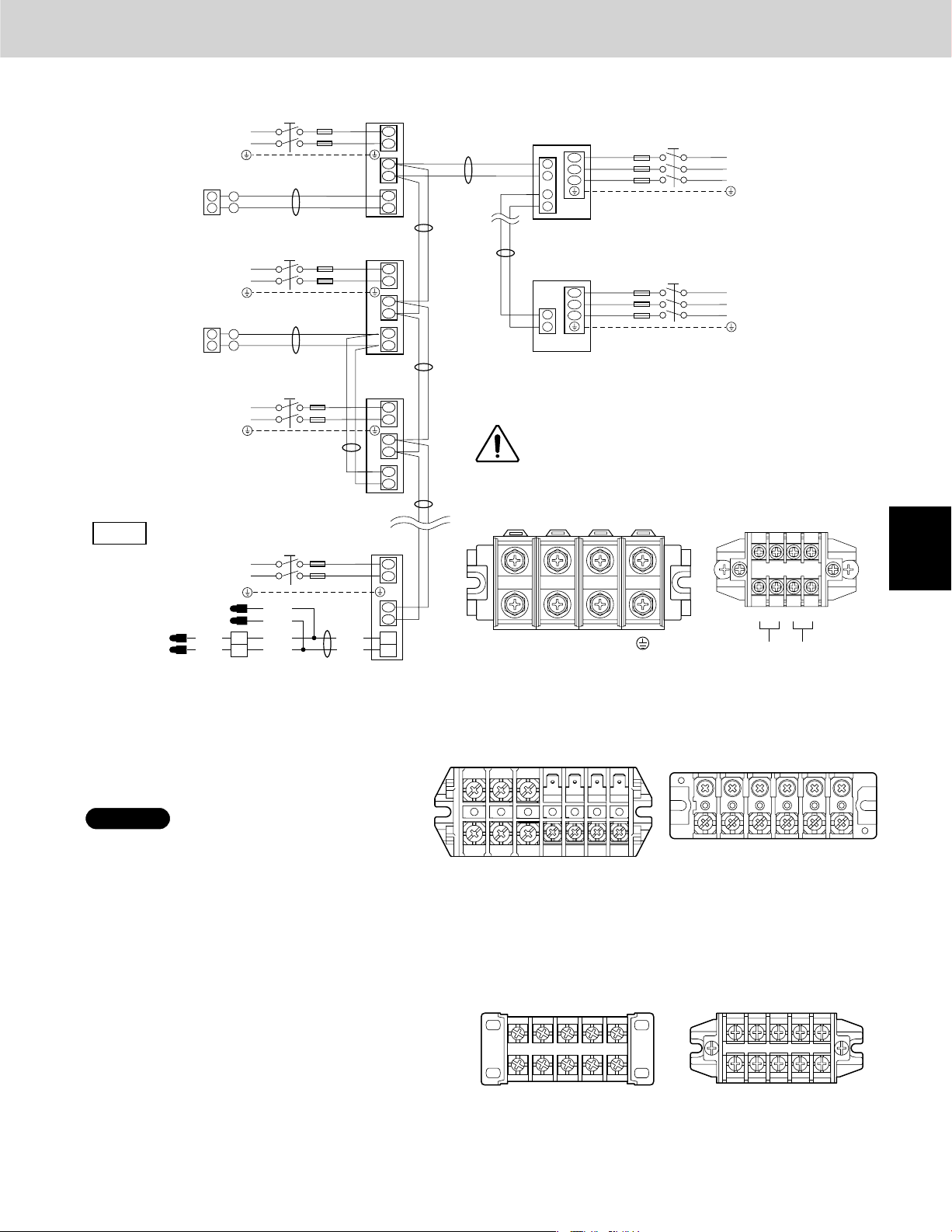
3. Electrical Wiring
Design of 3WAY VRF SYSTEM
3-3. Wiring System Diagram
1
2
212
1
2
1
2
1
L1
L2
Ground
L1
L2
Ground
L1
L2
Ground
L1
L2
Ground
BLK
WHT
BLK
WHT
Power supply
208 / 230V, 60Hz, 1-PH
Power supply
208 / 230V, 60Hz, 1-PH
Power supply
208 / 230V, 60Hz, 1-PH
K1 Type
Power supply
208 / 230V, 60Hz, 1-PH
Remote
Controller
Remote
Controller
WHT
BLK
Remote
Controller
WHT
BLK
BLK
WHT
CONNECTOR
2P(WHT)
Group control:
Indoor
B
C
BLK
WHT
unit (No. 1)
L1
L2
U1
U2
R1
R2
Indoor
unit (No. 2)
L1
L2
U1
U2
R1
R2
Indoor
unit (No. 3)
L1
L2
U1
U2
R1
R2
Indoor
unit (No. n)
L1
L2
U1
U2
3
1
Outdoor unit
A
A
A
*
INV unit
L1
1
L2
2
L3
3
4
Inter-outdoor unit control wiring
D
Outdoor unit
INV unit
L1
L2
3
L3
4
NOTE:
*
*
L1
Power supply
L2
208 / 230V, 60Hz, 3-PH
L3
Ground
L1
Power supply
L2
208 / 230V, 60Hz, 3-PH
L3
Ground
Disconnect switch
*
(Field Supply)
Disconnect Switch may be needed by the
National/Local code.
ALWAYS COMPLY WITH NATIONAL AND
LOCAL CODE REQUIREMENTS.
1
Outdoor Unit
A
4P terminal board
4P terminal board
2
1234
RC
(BLU)
L1 L2 L3
Inter-unit
control
wiring
Inter-outdoor
unit control
wiring
3
*
B
*
B
*
*
Indoor Unit
U1, E1 Types
7P terminal board
Y1, D1, T1, F1, M1, P1, R1 Types
6P terminal board
4
NOTE
(1)
Refer to Section 2 “3-2. Recommended Wire
Length and Wire Diameter for Power Supply
System” for the explanation of “A,” “B,” “C,”
and “D,” in the above diagram.
(2)
The basic connection diagram of the indoor
unit shows the 7P terminal board, so the
terminal boards in your equipment may differ
from the diagram.
(3)
Refrigerant Circuit (R.C.) address should be
set before turning the power on.
(4)
Regarding the R.C. address setting, refer to
Section 5 "TEST RUN." Address setting can be
executed by remote controller automatically.
1(L1) 2(L2)
Power
supply
K1 Type
Model : S-07MK1U6
S-09MK1U6
S-12MK1U6
5P terminal board 5P terminal board
1
(L1)2(L2)
Power
supply
2 - 25
U2
U1
Unit
control
Line
R1
R2
Remote
control
Line
Unit
control
Line
L1 L2 U1 U2 R1 R2
Power
supply
Unit
control
Line
Remote
control
Line
K1 Type
Model : S-18MK1U6
S-19MS1U6
S-24MK1U6
1
2U1U2U1U
(L1)2(L2)
Power
supply
Unit
control
Line
5
6
7
8
Page 40
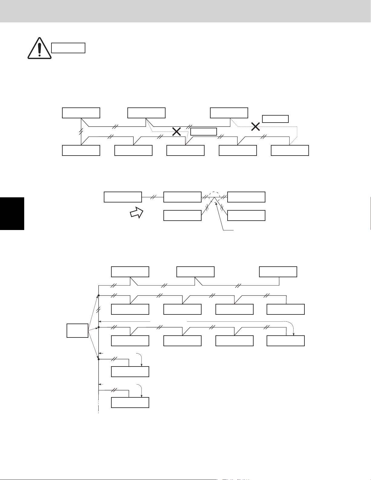
Design of 3WAY VRF SYSTEM
3. Electrical Wiring
CAUTION
(1)
When linking outdoor units in a network, disconnect the terminal extended from the short plug (CN003, 2P Black,
location: right bottom on the outdoor main control PCB) from all outdoor units except any one of the outdoor units.
(When shipping: In shorted condition.)
For a system without link (no connection wiring between outdoor units), do not remove the short plug.
(2)
Do not install the inter-unit control wiring in a way that forms a loop. (Fig. 2-1)
Outdoor unit
Indoor unit Indoor unit Indoor unit Indoor unit Indoor unit
(3) Do not install inter-unit control wiring such as star branch wiring. Star branch wiring causes mis-address setting.
1
2
3
(Fig. 2-2)
Outdoor unit Indoor unit Indoor unit
NO
(4) If branching the inter-unit control wiring, the number of branch points should be 16 or fewer.
(Branches less than 3.3 ft. are not included in the total branch number.) (Fig. 2-3)
Outdoor unit Outdoor unit Outdoor unit
Outdoor unit Outdoor unit
Prohibited
Prohibited
Fig. 2-1
Indoor unit Indoor unit
Branch point
Fig. 2-2
4
5
6
7
8
Branch
point
16 or fewer
Indoor unit Indoor unit Indoor unit Indoor unit
more than 3.3 ft.
Indoor unit
more than 3.3 ft.
Indoor unit
less than 3.3 ft.
Indoor unit
Indoor unit Indoor unit Indoor unit
Fig. 2-3
2 - 26
Page 41

3. Electrical Wiring
Loose wiring may cause the
WARNING
When connecting each power wire to the terminal,
follow the instructions on “How to connect wiring to the
terminal” and fasten the wire securely with the fixing
screw of the terminal plate.
How to connect wiring to the terminal
terminal to overheat or result
in unit malfunction. A fire
hazard may also exist.
Therefore, ensure that all
wiring is tightly connected.
Design of 3WAY VRF SYSTEM
For stranded wiring
(1)
Cut the wire end with cutting pliers, then strip the
insulation to expose the stranded wiring approx.
3/8" and tightly twist the wire ends. (Fig. 2-4)
(2)
Using a Phillips head screwdriver, remove the
terminal screw(s) on the terminal plate.
(3)
Using a ring connector fastener or pliers, securely
clamp each stripped wire end with a ring pressure
terminal.
(4)
Place the ring pressure terminal, and replace and
tighten the removed terminal screw using a
screwdriver. (Fig. 2-5)
Special
washer
Wire
Stranded wire
Strip 3/8"
Fig. 2-4
Screw
Ring pressure
terminal
Terminal plate
Wire
Fig. 2-5
Ring
pressure
terminal
Screw and
Special washer
Ring
pressure
terminal
1
2
3
4
2 - 27
5
6
7
8
Page 42

3. Electrical Wiring
Design of 3WAY VRF SYSTEM
1
2
3-4. Important Note When Wiring for Common Type
Connect the wires referring to the diagram.
Note that the control wirings (Low voltages) shall be
segregated from the power supply wires (High voltage)
as follows:
1.
Connect the Inter-unit control wiring to U1/U2
terminals and the remote control wire to R1/R2.
(excepting K1 type).
2.
Connect the power supply wires to “L1, L2” of the
terminal block. Be sure to connect the grounding
conductor of the incoming power supply to the earth
(ground) screw.
3.
Securely affix the power supply wires and remote
control wires by the clamping strap or clamping clip
not to cross each other and not to leave the wirings
loose. When loosening the clamping clip, twist the
strap and it will come undone.
Clamping clip
Twist
NOTE
Securely affix the 3-way wiring
harness with the remote
control wiring (U1 type).
U1 Type
Earth screw
Power wiring
(field supplied)
Clamping
clip
Conduit
Connection for
Solenoid Valve Kit
(for 3WAY)
Remote control wiring
and Inter-unit control wiring
(field supplied)
3
4
5
6
7
8
Clamping
clip
Remote control wiring
and Inter-unit control wiring
(field supplied)
Earth screw
Conduit
(field supplied)
Power wiring
(field supplied)
F1 TypeD1 Type
Earth screw
Power wiring
(field supplied)
Conduit
(field supplied)
Clamping
clip
Remote control wiring
and Inter-unit control wiring
(field supplied)
Connection for Solenoid
Valve Kit (for 3WAY)
2 - 28
Page 43

3. Electrical Wiring
Important Note When Wiring for Common Type (Continued)
Design of 3WAY VRF SYSTEM
E1 Type
Remote control wiring
and Inter-unit control
wiring (field supplied)
Earth screw
Power wiring
(field supplied)
Clamping
clip
Conduit
(field supplied)
T1 Type
Clamping
clip
Earth screw
Remote control wiring
(field supplied)
Power wiring
(field supplied)
Conduit
(field supplied)
1
2
M1 Type
Earth screw
Power wiring
(field supplied)
Clamping
clip
Conduit
(field supplied)
Remote control wiring
and Inter-unit control wiring
(field supplied)
P1, R1 Type
Clamping clip
Power wiring
(field supplied)
Earth screw
Conduit
Optional remote control
wiring (field supplied)
Connection
for Solenoid
Valve Kit
(for 3WAY)
3-way connection wiring
with harness(supplied)
3
4
5
6
7
8
2 - 29
Page 44
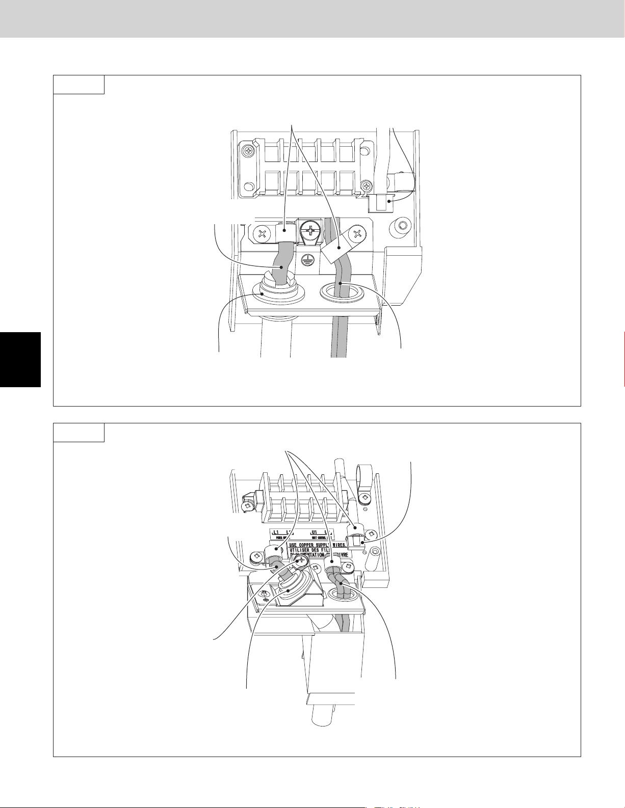
3. Electrical Wiring
Important Note When Wiring for Common Type (Continued)
K1 Type
Design of 3WAY VRF SYSTEM
1
2
Model : S-07MK1U6
S-09MK1U6
S-12MK1U6
Power wiring
(field supplied)
Conduit
(field supplied)
Clamping
strap
Connection for Solenoid
Valve Kit (for 3WAY)
Remote control wiring
and Inter-unit control
wiring (field supplied)
3
4
5
6
7
K1 Type
Model : S-18MK1U6
S-19MS1U6*
S-24MK1U6
Power wiring
(field supplied)
Earth screw
Clamping
strap
Conduit
(field supplied)
Connection for Solenoid
Valve Kit (for 3WAY)
Remote control wiring
and Inter-unit control
wiring (field supplied)
8
* Necessary to install the External Electronic Expansion Valve Kit (Optional : CZ-P56SVK1U)
2 - 30
Page 45

3. Electrical Wiring
3-5. Important Note When Wiring for Y1 Type
Connect the wires referring to the diagram.
Note that the control wirings (Low Voltages) shall be
segregated from the power supply wires (High Voltage)
as follows:
1.
Connect the Inter-unit control wiring to U1/U2
terminals and the remote control wire to R1/R2.
Then place and fix the two clasps so that the clasps
shall cover both the remote control wires, the Interunit control wiring and the 3-way wiring harness as
shown in the magnified drawing.
2.
Connect the grounding conductor of the incoming
power supply to the earth (ground) screw before
connecting the power supply conductors to “L1, L2”
of the terminal block.
3.
Securely affix the two power supply conductors (L1,
L2) in the wiring channel by the clamping strap as
shown.
Design of 3WAY VRF SYSTEM
Y1 Type
Connection for Solenoid
Valve Kit (for 3WAY)
Remote control wiring
(field supplied)
Clasp
Power wiring
(field supplied)
1
NOTE
Take care not to damage the control wirings by the clasp.
Do not leave the control wirings loose.
Entirely cover the control
wirings (Remote / Inter-unit
3WAY connection)
Remote control wiring and Inter-unit
control wiring (field supplied)
Conduit
(field supplied)
Earth screw
Clamping clip
2
3
4
5
6
2 - 31
7
8
Page 46

4. Installation Instructions
Design of 3WAY VRF SYSTEM
1
2
3
4
4-1. Selecting the Installation Site for Outdoor Unit
AVOID:
heat sources, exhaust fans, etc.
damp, humid or uneven locations
indoors (no-ventilation location)
DO:
choose a place as cool as possible.
choose a place that is well ventilated.
allow enough room around the unit for air intake/
exhaust and possible maintenance.
use lug bolts or equal to bolt down unit, reducing vibration
and noise.
Installation Space
Install the outdoor unit where there is enough space for
ventilation. Otherwise the unit may not operate properly. Fig.
2-7 shows the minimum space requirement around the outdoor
units when 3 sides are open and only 1 side is shuttered,
with open space above the unit. The mounting base should
be concrete or a similar material that allows for adequate
drainage. Make provisions for anchor bolts, platform height,
and other site-specific installation requirements.
Leave space open above the
CAUTION
unit.
Construct louvers or
other openings in the wall,
if necessary, to ensure
adequate ventilation.
NOTE
More than
2 in.
* More than 4 in.
* However, be sure to ensure a space of 1 ft. or more at
either the right side or the rear of the unit.
(Ceiling panel dimensions)
Exhaust fan
Hot air
Heat
Outdoor
unit
Fig. 2-6
Example of installation of 2 units
(When wall height is below 6 ft.)
* More than 4 in.
Fig. 2-7
113 (Ceiling panel dimensions)
(Ceiling panel dimensions)
35
4435
source
* More than 4 in.
(Ceiling panel dimensions)
35
More than
1.7 ft.
5
6
7
8
Do not do any wiring or tubing within 1 ft. of the front
panel, because this space is needed as a servicing
space for the compressor.
Ensure a base height of 4 in. or more to ensure that
drainage water does not accumulate and freeze
around the bottom of the unit.
If installing a drain pan, install the drain pan prior to
installing the outdoor unit.
* Make sure there is at least 6 in. between the outdoor
unit and the ground.
Also, the direction of the tubing and electrical wiring
should be from the front of the outdoor unit.
2 - 32
31-1/8
(Installation hole pitch)
7-7/8
109-1/16 (Installation hole pitch)
31-1/8
(Installation hole pitch)
Fig. 2-8
7-7/8
(Installation hole pitch)
31-1/8
35(Ceiling panel dimensions)
36-1/4 (Installation hole pitch)
37-1/2 (Maximum dimensions)
Unit: in.Top v ie w
Page 47

4. Installation Instructions
4-2. Removing Fin Guard for Heat Exchanger
After installation of the outdoor unit, detach the fin guard for
heat exchangers as following steps.
1.
Cut out the fin guard entirely attached to the panel and
remove it from the outdoor unit. Pay careful attention not
to damage the fin when cutting out the fin guard.
2.
If there is a case where easy to touch the sharp
aluminum fin of the outdoor unit, be sure to attach a
snow-proof ducting to the unit. It is recommended that
the outdoor unit be located away from the touched with
hands.
4-3. Shield for Horizontal Exhaust Discharge
It is necessary to install an air-discharge chamber (field
supply) to direct exhaust from the fan horizontally if it is
difficult to provide a minimum space of 7 ft. between the
air-discharge outlet and a nearby obstacle. (Fig. 2-9)
In regions with heavy snowfall,
CAUTION
the outdoor unit should be
provided with a solid, raised
platform and snow-proof
ducting (field supply). (Fig. 2-10)
Design of 3WAY VRF SYSTEM
Fig. 2-9
DO
1
2
4-4. Installing the Outdoor Unit in Heavy Snow
Areas
In locations where wind-blown snow can be a problem, snowproof ducting (field supply) should be fitted to the unit and
direct exposure to the wind should be avoided as much as
possible. (Fig. 2-11) The following problems may occur if proper
countermeasures are not taken:
The fan in the outdoor unit may stop running, causing the
unit to be damaged.
There may be no air flow.
The tubing may freeze and burst.
The condenser pressure may drop because of strong wind,
and the indoor unit may freeze.
4-5. Precautions When Installing in Heavy Snow
Areas
a)
The platform should be higher than the maximum snow
depth. (Fig. 2-10)
b)
The 2 anchoring feet of the outdoor unit should be used
for the platform, and the platform should be installed
beneath the air-intake side of the outdoor unit.
c)
The platform foundation must be solid and the unit must
be secured with anchor bolts.
d)
When installing on a roof subject to strong wind,
countermeasures must be taken to prevent the unit from
being overturned.
2 - 33
AVOID
Without snowproof ducting
(Without platform)
Fig. 2-10
Fig. 2-11
Fallen snow
With snowproof ducting
(High platform)
3
4
5
6
7
8
Page 48
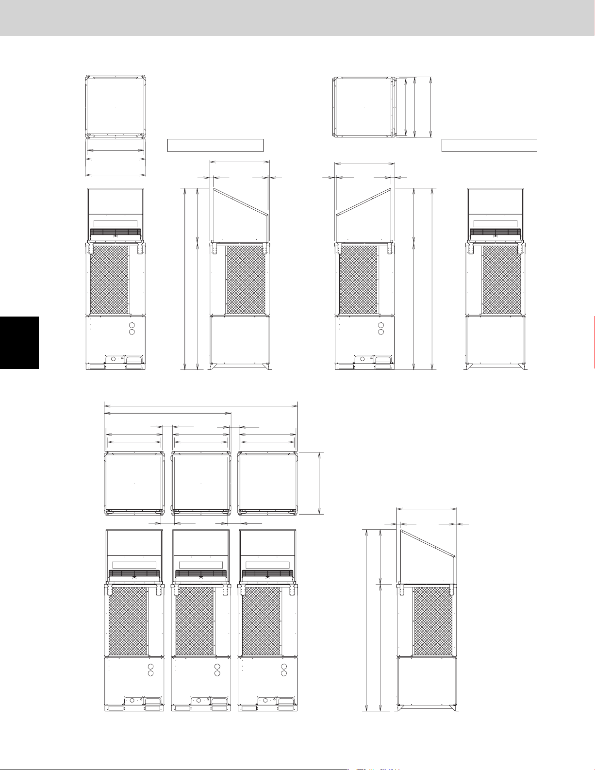
4. Installation Instructions
4-6. Dimensions of Wind Ducting
Reference diagram for air-discharge chamber (field supply)
Design of 3WAY VRF SYSTEM
unit: in.
1
2
3
4
33-3/16
35
(Ceiling panel dimensions)
35-1/4
(Maximum bracket dimensions)
Front view Right side view Front view Right side view
3-unit installation
(Installation hole pitch)
Ceiling panel Ceiling panel
Air direction: Front direction Air direction: Right direction
35
(Ceiling panel dimensions)
21
(32-1/8)
106-1/8
74-1/16
Note:
Can be installed so that the air direction is to the front, right, left or rear direction.
(3-unit installation: maximum dimensions)
113
(2-unit installation: maximum dimensions)
33-3/16 33-3/16 33-3/16
31-1/8
74-1/4
5-3/4
31-1/8
(Installation hole pitch)
5-3/4
31-1/8
(Installation hole pitch)
(Ceiling panel dimensions)
1
Top view
35
33-1/4
35-1/4
(Ceiling panel dimensions)
(Maximum bracket dimensions)
35
2
(32-1/8)
106-1/8
74-1/16
unit: in.
5
6
7
8
36-1/4
7-7/8 7-7/8
(Installation hole pitch)
(32-1/8)
106-1/8
74-1/16
Front view Right side view
35
(Ceiling panel dimensions)
21
2 - 34
Page 49

4. Installation Instructions
4-7. Dimensions of Snow Ducting
Reference diagram for snow-proof ducting (field supply)
Air direction:
Front direction
31-1/2
Design of 3WAY VRF SYSTEM
Air direction:
Right direction
54
31-1/2
31-1/2
(Air intake duct)
33-3/16
9-1/2 9-1/2
53-5/8
Note:
(Air outlet duct)
35
(Ceiling panel dimensions)
(54)
1 pc.
44-3/8
Front view
Can be installed so that the air direction is to the front, right, left or rear direction.
3-unit installation
Ceiling panel Ceiling panel
31-1/2
9-1/2
106-1/8
4 pc.
35 35 35
44
(Ceiling panel dimensions)
(32-1/8)
74-1/16
Right side view
113
35
32-7/8
35
31-1/2
33-3/16
(Air intake duct)
31-1/2
54
9-1/2 9-1/2 9-1/2
1
1
35
(Ceiling panel dimensions)
32-7/8
(54)
(Air outlet duct)
(Ceiling panel dimensions)
9-1/2 9-1/2
unit: in.
1
53-5/8
44-3/8
Right side viewFront view
2
3
Snowfall protection duct
(Field supply)
31-1/2
Air-discharge chamber
(Field supply)
Snowfall protection
duct (Field supply)
53-5/8
44-3/8
3
31-1/8
7-7/8 7-7/8
Board
(Field supply)
31-1/8 31-1/8
Board (Field supply)
Air-discharge chamber (Field supply)
131-3/4
Front view
35
37-3/8
36-1/4
Top view (Before installation of snowfall protection duct)
Snowfall protection duct
(Field supply)
31-1/2
35 (Ceiling panel dimensions)
7/82-1/8
Air-discharge chamber
(Field supply)
Snowfall protection duct
(Field supply)
44-3/8
Right side view
Ceiling panel
Snowfall protection
duct (Field supply)
53-5/8
44-3/8
9-1/2 9-1/2
106-1/8
74
4
unit: in.
5
6
7
53-5/8
8
2 - 35
Page 50

1
2
3
4. Installation Instructions
4-8. Transporting the Outdoor Unit
When transporting the unit, have it delivered as close to the installation site as
possible without unpacking. Use a hook for suspending the unit. (Fig. 2-12)
CAUTION
When hoisting the outdoor unit, pass ropes or straps under the bottom plate
as shown in the figure at right. When hoisting, the angle between the rope
and top panel must be 70° or greater so that the rope does not come into
contact with the fan guard.
(Use 2 lengths of rope 25 ft. long or longer.)
When passing the ropes through the square holes of the bottom plate:
Place the rope in the outer edge of the square holes.
Use protective panels or padding at all locations where the rope contacts the
outer casing or other parts to prevent scratching. In particular, use protective
material (such as cloth or cardboard) to prevent the edges of the top panel
from being scratched.
Be careful of the fan.
There is danger of injury if the fan starts to turn during inspection. Be sure to
turn OFF the remote power switch before beginning inspection.
4-9. Installing the Outdoor Unit
(1)
Use anchor bolts (M12 or 15/32") or similar to securely anchor the unit in
place. (Fig. 2-13)
(2)
Be sure the rubber vibration insulator and platform extend to the inside of
the legs. In addition, the washers used to anchor the unit from the top must
be larger than the installation anchor holes. (Figs. 2-13 and 2-14)
(Positions where anchor bolts are fastened)
Installation anchor hole (4-19/32 25/32 oval holes)
unit: in.
Design of 3WAY VRF SYSTEM
Fig. 2-12
Plate leg
Anchor bolts
Washer
25/32
3-15/32
(3-15/16)
(3-15/16)
The vibration insulator, base, or platform must
be large enough to bear the full surface of the
base plate legs.
Vibration insulator
1-31/32
Base
Unit: in.
4
5
6
7
8
31-1/8
(Installation hole pitch)
35
(Ceiling panel dimensions)
35
(Ceiling panel dimensions)
3
31-1/8
(Installation hole pitch)
35
113 (Ceiling panel dimensions)
(Ceiling panel dimensions)
109 (Installation hole pitch)
37-1/2
36-1/4
(Installation hole pitch)
(Ceiling panel dimensions)
(Installation hole pitch)
Fig. 2-15
(Maximum dimensions)
35
31-1/8
Top v i ew
(Ceiling panel dimensions)
35
31-1/8
(Installation hole pitch)
4 – 19/32 25/32 hole
35
37-1/2
36-1/4
(Installation hole pitch)
(Ceiling panel dimensions)
(Maximum dimensions)
Surface where
installation anchor
brackets are
installed
1-31/32
Fig. 2-13
(Detailed view of legs)
19/32
Unit: in.
1-33/64
Fig. 2-14
2 - 36
Page 51

Design of 3WAY VRF SYSTEM
4. Installation Instructions
4-10. Remove the Brackets Used for Transport
After installing the unit, remove the
2 transport brackets from the front
and rear (4 brackets total).
4-11. Routing the Tubing
The tubing can be routed out either from the front or from the bottom. (Fig. 2-17)
The connecting valve is contained inside the unit. Therefore, remove the front panel. (Fig. 2-17)
(1) If the tubing is routed out from the front, use cutting pliers or a similar tool to cut out the tubing outlet slit (part
indicated by ) from the tubing cover. (Figs. 2-17 and 2-18)
(Fig. 2-16)
Remove the 2 screws
(8 screws total)
Remove the 2 transport brackets from
the front and rear (4 brackets total)
Fig. 2-16
1
Front
Bottom
Tubing cover
Remove 2 screws
(2) If the tubing is routed out from the bottom, remove
the slit part (
Use a drill bit approximately 13/64" dia. to create
holes at the 4 slit hole indentations (openings).
Punch out the slit part ( ).
Be careful not to damage the base plate.
).
Use cutting pliers or similar
tool to cut cover out
Remove 11 panel
screws from front
panel
Fig. 2-17
Indentation
(4 locations)
Slit hole
2
3
4
5
6
7
2 - 37
Fig. 2-18
8
Page 52

1
2
Design of 3WAY VRF SYSTEM
4. Installation Instructions
4-12. Prepare the Tubing
Material: Use C1220 phosphorous deoxidized copper as described in JIS H3300, “Copper and Copper Alloy
Seamless Pipes and Tubes.”
(For tubes that are ø7/8" (ø22.22 mm) or larger, use 1/2H material or H material. For all others use O material.)
Tubing size
Use the tubing size indicated in the table below.
When cutting the tubing, use a tube cutter, and be sure to remove any burrs.
(The same applies to distribution tubing (optional).)
When bending the tubes, bend each tube using a radius that is at least 4 times the outer diameter of the tube.
When bending, use sufficient care to avoid crushing or damaging the tube.
For flaring, use a flare tool, and be sure that flaring is performed correctly.
Use sufficient caution during preparation of the tubing. Seal the tube ends by
CAUTION
Refrigerant tubing (Existing tubing can be used.)
Outer dia. Thickness Outer dia. Thickness
ø1/4" (ø6.35) t1/32" (t0.8) ø3/4" (ø19.05) over t5/128" (t1.0)
ø3/8" (ø9.52) t1/32" (t0.8) ø7/8" (ø22.22) t5/128" (t1.0)
ø1/2" (ø12.7) t1/32" (t0.8) ø1-1/8" (ø28.58) t5/128" (t1.0)
ø5/8" (ø15.88) t5/128" (t1.0) ø1-3/8" (ø34.92) t3/64" (t1.1)
4-13. Connect the Tubing
means of caps or taping to prevent dust, moisture, or other foreign substances
from entering the tubes.
Tubing size (mm)
3
4
5
6
7
8
Use the supplied connector tubing. (See figure below.)
72 type (6-Ton)
2
34
96 type (8-Ton)
34
1
Refrigerant
tubing
Suction tube Brazed connection
1
Discharge tube Brazed connection
2
Liquid tube Brazed connection No
3
Balance tube Flared connection No
4
2
1
Refrigerant
tubing
Suction tube Brazed connection
1
Discharge tube Brazed connection
2
Liquid tube Brazed connection No
3
Balance tube Flared connection No
4
Connection method
Connection method
Refrigerant tube port
Use caulking, putty, or a similar material to fill any
gaps at the refrigerant tube port ( ) in order to
prevent rainwater, dust or foreign substances from
entering the unit.
* Perform this work even if the tubing is routed out
in a downward direction.
Use supplied
connector tube?
No
No
Use supplied
connector tube?
Yes (ø3/4" → ø7/8")
Yes (ø5/8" → ø3/4")
Tubing routed out forward
2 - 38
Tubing
cover
Tubing routed out downward
Base plate
Page 53

4. Installation Instructions
Design of 3WAY VRF SYSTEM
Tighten each cap as specified below.
Tightening torque for each cap
Service port cap
(width 19/32")
Valve cap
(width 55/64")
Flare nut
(valve dia. ø3/8")
Do not apply an adjustable wrench
to the hexagonal part.
Do not use two adjustable wrenches
when removing or installing the balance
tube flare nut. In particular, do not apply
an adjustable wrench to the hexagonal
part at the top of the valve.
(If force is applied to this part,
gas leakage will occur.)
60 – 100 lbs · in (70 – 120 kgf · cm)
170 – 220 lbs · in (200 – 250 kgf · cm)
300 – 360 lbs · in (340 – 420 kgf · cm)
Valve cap
Flare nut
Service port cap
Use two adjustable wrenches, as shown in the figure,
when removing the liquid tube valve flare nut.
1. Do not apply a wrench to the valve cap when removing or
installing the flare nuts. Doing so may damage the valve.
2. If the valve cap is left off for a long period of time, refrigerant
leakage will occur. Therefore, do not leave the valve cap off.
3. Applying refrigerant oil to the flare surface can be effective in
preventing gas leakage, however be sure to use a refrigerant
oil which is suitable for the refrigerant that is used in the system.
(This unit utilizes R410A refrigerant, and the refrigerant oil is
ether oil (synthetic oil). However, hub oil (synthetic oil) can also
be used.)
1
Precautions for brazing
Be sure to replace the air inside the tube with nitrogen to prevent oxide film from forming during the brazing process.
Be sure to use a damp cloth or other means to cool the valve unit during brazing.
Work method
CAUTION
Field-supply tube
Brazing locations
Be sure to use nitrogen. (Oxygen, CO
1. 2
2.
Use a pressure-reducing valve on the nitrogen tank.
3.
Do not use agents intended to prevent the formation of oxide film. They will adversely affect the
refrigeration oil, and may cause equipment failure.
4.
The balance tube is not used if only 1 outdoor unit is installed.
Use the unit in the same conditions as when it was shipped from the factory.
Taping
Remote valve
Pressure-reducing valve (regulator)
Nitrogen
, and CFC must not be used.)
2
3
4
5
6
2 - 39
7
8
Page 54

5. HOW TO PROCESS TUBING
Design of 3WAY VRF SYSTEM
1
2
5. HOW TO PROCESS TUBING
The liquid tubing side is connected by a flare nut, and the
gas tubing side is connected by brazing.
5-1. Connecting the Refrigerant Tubing
Use of the Flaring Method
Many of conventional split system air conditioners employ
the flaring method to connect refrigerant tubes which run
between indoor and outdoor units. In this method, the
copper tubes are flared at each end and connected with
flare nuts.
Flaring Procedure with a Flare Tool
(1)
Cut the copper tube to the required length with a tube
cutter. It is recommended to cut approx. 1 – 2 ft. longer
than the tubing length you estimate.
(2)
Remove burrs at the end of the copper tube with a tube
reamer or file. This process is important and should be
done carefully to make a good flare. (Fig. 2-19)
NOTE
When reaming, hold the tube end downward and be sure
that no copper scraps fall into the tube. (Fig. 2-20)
Deburring
AfterBefore
Fig. 2-19
Copper
tubing
Reamer
Fig. 2-20
3
4
5
6
7
(3)
Remove the flare nut from the unit and be sure to
mount it on the copper tube.
(4)
Make a flare at the end of copper tube with a flare
tool. (Fig. 2-21)
NOTE
A good flare should have the following characteristics:
inside surface is glossy and smooth
edge is smooth
tapered sides are of uniform length
Flare nut
Copper
tubing
Flare tool
Fig. 2-21
8
2 - 40
Page 55

5. HOW TO PROCESS TUBING
Caution Before Connecting Tubes Tightly
(1)
Apply a sealing cap or water-proof tape to prevent
dust or water from entering the tubes before they are
used.
(2)
Be sure to apply refrigerant lubricant to the matching
surfaces of the flare and union before connecting them
together. This is effective for reducing gas leaks.
(Fig. 2-22)
(3)
For proper connection, align the union tube and flare
tube straight with each other, then screw in the flare
nut lightly at first to obtain a smooth match. (Fig. 2-23)
Adjust the shape of the liquid tube using a tube bender
at the installation site and connect it to the liquid tubing
side valve using a flare.
Design of 3WAY VRF SYSTEM
Apply refrigerant
lubricant
Fig. 2-22
Union
Fig. 2-23
Flare nut
Cautions During Brazing
Replace air inside the tube with nitrogen gas to
prevent copper oxide film from forming during the
brazing process. (Oxygen, carbon dioxide and
Freon are not acceptable.)
Do not allow the tubing to get too hot during
brazing. The nitrogen gas inside the tubing may
overheat, causing refrigerant system valves to
become damaged. Therefore allow the tubing to
cool when brazing.
Use a reducing valve for the nitrogen cylinder.
Do not use agents intended to prevent the
formation of oxide film. These agents adversely
affect the refrigerant and refrigerant oil, and may
cause damage or malfunctions.
5-2. Connecting Tubing Between Indoor and
Outdoor Units
(1)
Tightly connect the indoor-side refrigerant tubing
extended from the wall with the outdoor-side tubing.
(2)
To fasten the flare nuts, apply specified torque as at
right:
When removing the flare nuts from the tubing
connections, or when tightening them after
connecting the tubing, be sure to use 2 adjustable
wrenches or spanners as shown. (Fig. 2-24)
If the flare nuts are over-tightened, the flare may be
damaged, which could result refrigerant leakage and
cause in injury or asphyxiation to room occupants.
For the flare nuts at tubing connections, be sure to
use the flare nuts that were supplied with the unit,
or else flare nuts for R410A (type 2). The refrigerant
tubing that is used must be of the correct wall
thickness as shown in the table at right.
Torque wrench
Indoor unit
Outdoor unit
Fig. 2-24
Tube diameter
ø1/4" (ø6.35 mm)
ø3/8" (ø9.52 mm)
ø1/2"(ø12.7 mm)
ø5/8" (ø15.88 mm)
ø3/4" (ø19.05 mm)
Because the pressure is approximately 1.6 times
higher than conventional refrigerant pressure, the
use of ordinary flare nuts (type 1) or thin-walled
tubes may result in tube rupture, injury, or
asphyxiation caused by refrigerant leakage.
In order to prevent damage to the flare caused by
over-tightening of the flare nuts, use the table
above as a guide when tightening.
When tightening the flare nut on the liquid tube, use
an adjustable wrench with a nominal handle length
of 7-7/8 in.
Tightening torque,
approximate
120 – 160 lbs·inch
(140 – 180 kgf·cm)
300 – 360 lbs·inch
(340 – 420 kgf·cm)
430 – 480 lbs·inch
(490 – 550 kgf·cm)
590 – 710 lbs·inch
(680 – 820 kgf·cm)
870 – 1040 lbs·inch
(1000 – 1200 kgf·cm)
Spanner
Tube thickness
1/32"
(0.8 mm)
1/32"
(0.8 mm)
1/32"
(0.8 mm)
5/128"
(1.0 mm)
over 5/128"
(1.0 mm)
1
2
3
4
5
6
7
8
2 - 41
Page 56

5. HOW TO PROCESS TUBING
Design of 3WAY VRF SYSTEM
1
2
3
4
5-3. Insulating the Refrigerant Tubing
Tubing Insulation
Thermal insulation must be applied to all unit tubing,
including the distribution joint (purchased separately).
(Fig. 2-25)
* For gas tubing, the insulation material must be heat
resistant to 248°F or above. For other tubing, it must
be heat resistant to 176°F or above.
Insulation material thickness must be 25/64 in. or
greater.
If the conditions inside the ceiling exceed DB 86°F
and RH 70%, increase the thickness of the gas
tubing insulation material by 1 step.
If the exterior of the outdoor
CAUTION
Taping the flare nuts
Wind the white insulation tape around the flare nuts at
the gas tube connections. Then cover up the tubing
connections with the flare insulator, and fill the gap at the
union with the supplied black insulation tape. Finally,
fasten the insulator at both ends with the supplied vinyl
clamps. (Fig. 2-26)
unit valves has been finished
with a square duct covering,
make sure you allow
sufficient space to use the
valves and to allow the
panels to be attached and
removed.
Two tubes arranged together
Liquid tubing
Three tubes arranged together
Liquid tubing
Insulation
Four tubes arranged together
Discharge tubing
Balance tubing
Sealer (supplied)
Unit side
insulator
Flare nut
Insulation
Cosmetic
(finishing) tape
Cosmetic
(finishing) tape
Insulation
Fig. 2-25
Insulation tape (white)
(supplied)
Vinyl clamps (supplied)
Fig. 2-26
Gas tubing
Gas tubing
Balance tubing
Suction tubing
Liquid tubing
Flare insulator (supplied)
Tube insulator
(not supplied)
Heat resistant
248°F or above
5
6
7
8
2 - 42
Page 57

5. HOW TO PROCESS TUBING
5-4. Taping the Tubes
(1)
At this time, the refrigerant tubes (and electrical wiring
if local codes permit) should be taped together with
armoring tape in 1 bundle. To prevent the
condensation from overflowing the drain pan, keep the
drain hose separate from the refrigerant tubing.
(2)
Wrap the armoring tape from the bottom of the
outdoor unit to the top of the tubing where it enters
the wall. As you wrap the tubing, overlap half of each
previous tape turn.
(3)
Clamp the tubing bundle to the wall, using 1 clamp
approx. each ft. (Fig. 2-27)
NOTE
Do not wind the armoring tape too tightly since this will
decrease the heat insulation effect. Also ensure that the
condensation drain hose splits away from the bundle and
drips clear of the unit and the tubing.
Design of 3WAY VRF SYSTEM
Insulated tubes
Fig. 2-27
Apply putty here
Clamp
Drain hose
1
5-5. Finishing the Installation
After finishing insulating and taping over the tubing, use
sealing putty to seal off the hole in the wall to prevent rain
and draft from entering. (Fig. 2-28)
2
Tubing
Fig. 2-28
3
4
5
6
2 - 43
7
8
Page 58
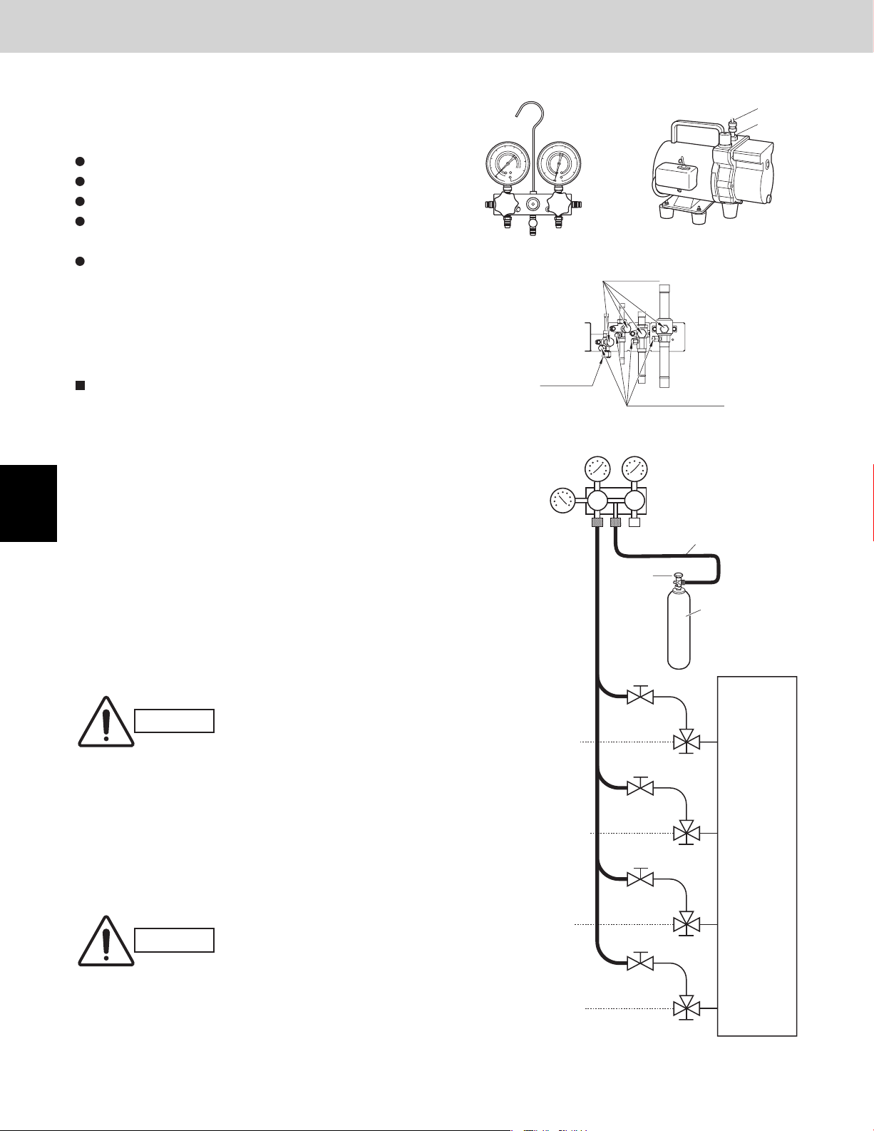
6. AIR PURGING
Design of 3WAY VRF SYSTEM
1
2
6. AIR PURGING
Air and moisture in the refrigerant system may have
undesirable effects as indicated below.
pressure in the system rises
operating current rises
cooling (or heating) efficiency drops
moisture in the refrigerant circuit may freeze and block
capillary tubing
water may lead to corrosion of parts in the refrigerant
system
Therefore, the indoor unit and tubing between the indoor
and outdoor unit must be leak tested and evacuated to
remove any noncondensables and moisture from the
system.
Air Purging with a Vacuum Pump (for Test Run)
Preparation
Check that each tube between the indoor and outdoor
units have been properly connected and all wiring for the
test run has been completed. Remove the valve caps
from all service ports on the outdoor unit. (Fig. 2-30) Note
that all service valves on the outdoor unit are kept closed
at this stage. The balance tube leak test is not necessary
if only 1 outdoor unit is installed.
Manifold gauge
Fig. 2-29a
Flare nut
Pressure
gauge
Vacuum pump
Outlet
Inlet
Fig. 2-29b
Valve cap
Service port cap
Fig. 2-30
Manifold valve
Lo Hi
Charge hose
3
4
5
6
7
8
Leak test
(1) Attach a manifold valve (with pressure gauges) and
dry nitrogen gas cylinder to all service ports with
charge hoses.
The balance tube leak test is not necessary if only 1
outdoor unit is installed.
Use a manifold valve for air
CAUTION
(2) Pressurize the system to no more than 450 psig
(31 kgf/cm2G) with dry nitrogen gas and close the
cylinder valve when the gauge reading reaches
450 psig (31 kgf / cm2G). Then, test for leaks with
liquid soap.
CAUTION
purging. If it is not available,
use a stop valve for this
purpose. The “Hi” knob of
the manifold valve must
always be kept closed.
To avoid nitrogen entering the
refrigerant system in a liquid
state, the top of the cylinder
must be higher than the
bottom when you pressurize
the system. Usually, the
cylinder is used in a vertical
standing position.
Suction
tube
Discharge
tube
Liquid
tube
Balance
tube
Cylinder
valve
Open
Open
Open
Open
Fig. 2-31
Nitrogen gas cylinder
(In vertical standing
position)
Close
Outdoor unit
Close
Close
Close
2 - 44
Page 59

6. AIR PURGING
(3)
Do a leak test of all joints of the tubing (both indoor
and outdoor) and all service valves. Bubbles
indicate a leak. Wipe off the soap with a clean cloth
after a leak test.
(4)
After the system is found to be free of leaks, relieve
the nitrogen pressure by loosening the charge hose
connector at the nitrogen cylinder. When the system
pressure is reduced to normal, disconnect the hose
from the cylinder.
Evacuation
(1) Attach the charge hose end described in the
preceding steps to the vacuum pump to evacuate
the tubing and indoor unit. Confirm that the “Lo”
knob of the manifold valve is open. Then, run the
vacuum pump. The operation time for evacuation
varies with the tubing length and capacity of the
pump.
Evacuation is not necessary for the balance tube if
only 1 outdoor unit is installed.
Pressure
gauge
Suction
tube
Design of 3WAY VRF SYSTEM
Manifold valve
Lo Hi
Vacuum pump
Open
Close
1
NOTE
The vacuum condition should be less than
–14.7 psig (–755 mmHg, 5 Torr).
Discharge
tube
Liquid
tube
Balance
tube
Open
Open
Open
Fig. 2-32
Close
Close
Close
2
Outdoor unit
3
4
5
6
2 - 45
7
8
Page 60

6. AIR PURGING
Design of 3WAY VRF SYSTEM
1
2
3
4
5
6
(2) When the desired vacuum is reached, close the “Lo”
knob of the manifold valve and turn off the vacuum
pump. Please confirm that the gauge pressure is
under –14.7 psig (–755 mmHg, 5 Torr) after 4 to 5
minutes of vacuum pump operation.
Charging additional refrigerant
CAUTION
Use a cylinder designed for
use with R410A.
Charging additional refrigerant (calculated from the
liquid tube length as shown in Section “Additional
Refrigerant Charge (page 2-5)”) using the liquid tube
service valve. (Fig. 2-33)
Use a balance or scale to measure the refrigerant
accurately.
If the additional refrigerant charge amount cannot be
charged at once, charge the remaining refrigerant in
liquid form by using the suction tube service valve
with the system in Cooling mode at the time of test
run. (Fig. 2-34)
Close the valve on the cylinder containing R410A.
Finishing the job
(1)
With a flathead screwdriver, turn the liquid tube
service valve counter-clockwise to fully open the
valve.
(2)
Turn the all service valve counter-clockwise to fully
open the valve.
(3)
Close all stop valves and loosen the “Lo” knob of
the manifold valve.
(4)
Loosen the charge hose connected to all service
port, then remove the hose.
(5)
Replace all valve caps at all service ports and fasten
them securely.
This completes air purging with a vacuum pump.
The air conditioner is now ready for a test run.
Pressure
gauge
Suction
tube
Discharge
tube
Liquid
tube
Balance
tube
Manifold valve
Suction
tube
Discharge
tube
Lo Hi
Close
Close
Open
Close
Fig. 2-33
Open
Close
Valve
Liquid
R410A
Close
Outdoor unit
Close
Close
Close
Open
Outdoor unit
Open
7
8
Close
Liquid
tube
Open
Close
Balance
tube
Open
Fig. 2-34
2 - 46
Page 61

7. Optional Parts
7-1. Distribution Joint Kits
CZ-P900PH1U (for R410A)
How to Attach Distribution Joint
1. Accompanying Parts
Check the contents of your distribution joint kit.
2. Distribution Joint Kits (with insulation)
Design of 3WAY VRF SYSTEM
CZ-P900PH1U
Suction Tube
300
BC
Distribution
Joint
Insulators for both the Suction tube and the Discharge tube are the same.
*
Suction tube and Discharge tube are similar in sizes and both the tube entrances have the same diameter.
*
So the both Distribution joints can fit into different tubes. Since the diameter of the tube ends for both Suction and
Discharge tube are different, take care not to connect the distribution joint different.See the "#" marks on the above
figures.
#C
#C
D
E
C
Insulation
USE:For outdoor unit (Capacity after distribution joint is 90.0kW or less.)
Discharge Tube
300
D
E
Reducing
Joints
ED C
#C
#C
D
E
F
Insulation
C
FDE
Liquid Tube
G
F
E
340
Insulation
Size of connection point on each part (Shown are inside diameters of tubing)
Size
mm
Inch
Part B
Ø34.92
1-3/8
Part C
Ø28.58
1-1/8
Part D
Ø25.4
1
Part E
Ø22.22
7/8
Part F
Ø19.05
3/4
Part G
Ø15.88
5/8
Part H
Ø12.7
1/2
Part I
Ø9.52
3/8
GFEEFG
IHIH
1
2
3
4
Using a tube cutter, cut the joints at the diameter required to match the outside diameter of the tubing you are
connecting.
(This is usually done at the installation site.) The tube diameter depends on the total capacity of the outdoor unit.
Note that you do not have to cut the joints if it already matches the tubing end size. For size selection of the tube
diameter, refer to the installation instructions provided with the outdoor unit.
NOTE
Avoid forceful cutting that may harm the shape of the joints or tubing.
(Inserting the tubing will not be possible if the tube shape is not proper.)
Stopper(boss)
Cutting point
Cut off as far away from stopper as possible.
After cutting the joints, be sure to remove burrs on the inside of the joints.
(If the joints have been squashed or dented badly, reshaped them using a
tube spreader.)
Make sure there is no dirt or other foreign substances inside the distribution
joint.
2 - 47
Make this as long as
possible.
Insertion length of the
connecting tube
5
6
7
8
Page 62

7. Optional Parts
The distribution joint can be either horizontal or vertical.
In the case of horizontal, the L-shaped tubing must be slanted slightly upward (15° to 90° ).
Design of 3WAY VRF SYSTEM
1
2
15 to 30°
Outdoor unit
Side
In case of horizontal position
When brazing, replace air inside the tube with nitrogen gas to prevent copper oxide from forming.
To insulate the distribution joint, use the supplied tubing insulation.
(If using insulation other than that supplied, make sure that its heat resistance is 248°F or higher.)
For additional details, refer to the installation instructions provided with the outdoor unit.
upward slant
Indoor unit
Side
In case of vertical position
(directed upward or downward)
Direction of Distribution Joint
Outdoor
unit
Outdoor
unit
Direction of
Distribution Joint
Indoor unit
3
4
5
6
7
8
2 - 48
Page 63

7. Optional Parts
CZ-P224BH1U, CZ-P680BH1U, CZ-P1350BH1U (for R410A)
How to Attach Distribution Joint
1. Accompanying Parts
Check the contents of your distribution joint kit.
2. Distribution Joint Kits (with insulation)
Design of 3WAY VRF SYSTEM
CZ-P224BH1U
Suction Tube
F
G
F
Distribution
Joint
Insulation Insulation
CZ-P680BH1U
Suction Tube
300
FED C
Insulation
Insulators for both the Suction tube and the Discharge tube are the same.
*
*
Suction tube and Discharge tube are similar in sizes and both the tube entrances have the same diameter.
GH
F
G
H
Reducing
Joints
USE:For indoor unit(Capacity after distribution joint is greater than 22.4kW and no more than 68.0kW.)
#C
#C
D
E
F
G
USE:For Indoor unit(Capacity after distribution joint is 22.4kW or less.)
Discharge Tube
186210 235
DFE
G
Discharge Tube
G
DEF
C
Insulation
300
G
HH
H
G
GH
EF
#D
#D
E
F
G
H
Liquid Tube
I
H
Insulation
Liquid Tube
I
H
G
F
E
340
Insulation
HIIH
GFEEFG
So the both Distribution joints can fit into different tubes. Since the diameter of the tube ends for both Suction and
Discharge tube are different, take care not to connect the distribution joint different. See the "#" marks on the above
figures.
Unit:mm
1
Unit:mm
2
HIHI
3
4
5
CZ-P1350BH1U
USE:For indoor unit(Capacity after distribution joint is greater than 68.0kW and no more than 135.0kW.)
Suction Tube·Discharge Tube
H
G
F
E
D
C
A
BBB
90
Insulation
ECDAFFCDAE
Liquid Tube
I
H
G
F
E
340
Insulation
GFEEFG
HIHI
2 - 49
Unit:mm
6
7
8
Page 64

1
2
Design of 3WAY VRF SYSTEM
7. Optional Parts
Size of connection point on each part (Shown are inside diameters of tubing)
Size Part D E traPA traP H traPB traP Part G Part IF traPC traP
mm
Inch
3. Making Branch Connections
Using a tube cutter,cut the joints at the diameter required to match the outside diameter of the tubing you are
connecting.
(This is usually done at the installation site.) The tube diameter depends on the total capacity of the indoor unit.
Note that you do not have to cut the joints if it already matches the tubing end size. For size selection of the tube
diameter, refer to the installation instructions provided with the outdoor unit.
NOTE
Avoid forceful cutting that may harm the shape of the joints or tubing.
(Inserting the tubing will not be possible if the tube shape is not proper.)
Cut off as far away from stopper as possible.
After cutting the joints,be sure to remove burrs on the inside of the joints.
(If the joints have been squashed or dented badly, reshaped them using a tube spreader.)
Make sure there is no dirt or other foreign substances inside the distribution joint.
The distribution joint can be either horizontal or vertical.
In the case of horizontal, the L-shaped tubing must be
slanted slightly upward (15° to 30°).
Ø25.4 22.22Ø1.83Ø 7.21Ø31.75Ø Ø15.88 Ø9.5250.91Ø85.82Ø
18/72/1-1 2/14/1-1 5/8 3/84/38/1-1
Stopper (boss)
Cutting point
3
4
5
6
7
Indoor unit
Outdoor unit
Side
In case of horizontal position
When brazing,replace air inside the tube with nitrogen gas to
prevent copper oxide from forming.
To insulate the distribution joint, use the supplied tubing
insulation.
(If using insulation other than that supplied, make sure
that its heat resistance is 248˚F or higher.)
For additional details, refer to the installation instructions
provided with the outdoor unit.
Side
15 to 30°
upward slant
Make this as long as
possible.
Insertion length of the
connecting tube
In case of vertical position
(directed upward or downward)
8
2 - 50
Page 65

7. Optional Parts
7-2. Solenoid Valve Kit for 3WAY VRF System
CZ-P56HR1U, CZ-P160HR1U
For safety installation and trouble-free operation, you must:
Carefully read this instruction booklet before beginning.
Follow each installation or repair step exactly as shown.
Observe all local, state, and national electrical codes.
Pay close attention to all warning and caution notices given in this manual.
Design of 3WAY VRF SYSTEM
WARNING
CAUTION
1. Accessories
Part Name Figure Q'ty Remarks
Washer
Hanging hook
M4 screw ( L=15/32")
Tapping screw ( L=5/16")
Wire holder
3-Way connect wire
(6.5ft.)
This symbol refers to a hazard or unsafe practice which can result in severe
personal injury or death.
This symbol refers to a hazard or unsafe practice which can result in personal
injury or product or property damage.
For hanging bolts
2
Used to hang the Solenoid Valve Kit
1
For hanging hook
4
4
For Solenoid Valve Relay Kit
For Solenoid Valve Relay Kit wiring
1
1
1
2
3
ACC-3WAY-AAB
Solenoid Valve Relay Kit
1
2. Positioning for Installation
The solenoid valve kit produces some refrigerant noise. If it is to be installed in a quiet place such as a hospital,
library or hotel, it is recommended that the solenoid valve kit be installed in the ceiling of a corridor, etc. apart
from the room.
Room Room
Indoor unit Indoor unit
Solenoid valve kit
Corridor
Recommended
installation
Room Room
Indoor unit Indoor unit
Avoid
Solenoid valve kit
Corridor
2 - 51
4
5
6
7
8
Page 66

7. Optional Parts
Be sure to secure the solenoid valve kit to the
structure and the hanging bolts, etc. using the top or
side holes of the hanging hooks. Do not place the
solenoid valve kit directly on the ceiling surface.
When installing the solenoid valve kit,
install it with the top surface facing upward.
(See the figure shown in the subsection "How to use
the fittings" in " 3. Valve Dimensions and Hanging
Method.")
Provide a service space of 7-7/8" or more in front
of the installing site.
Never conduct drilling or welding on the sheet
metal.
Place the solenoid valve kit so that it does
not hinder draining.
Do not cover air holes.
remember to
Design of 3WAY VRF SYSTEM
Front side
7-7/8" or more
Service space
1
2
3
4
5
3. Valve Dimensions and Hanging Method
There are 2 types of solenoid valve kits: type 56
and type 160. The corresponding indoor unit model
capacities are shown in the table at right.
Gas tube ID 1/2" ( 5/8" )
1-21/32
3-21/32
4-7/32
Liquid tube ID 1/4" ( 3/8" )
Hanging hook
Holes for suspension bolt ø15/32
5-55/64
Solenoid Valve Kit
CZ-P56HR1U
CZ-P160HR1U
Discharge tube ID 1/2"
Front side
4-21/64 4-21/64 5-55/64
Indoor Unit Capacity
7 -18 Type
24 - 48 Type
63/64
2-31/64
3-15/16
6-29/64
8-15/32
Liquid tube ID 3/8"
Suction tube ID 5/8"
6
7
8
53/64 2-63/64
NOTE
This figure shows the unit with suspension fittings attached.
2 - 52
43/64
1-7/64
Cover of electrical components
7/16
7-41/64
5-55/64
unit : in.
9-29/64
Page 67

7. Optional Parts
How to use the fittings
Design of 3WAY VRF SYSTEM
Suspension bolt (3/8" or M10) (field supplied)
Nut (field supplied) (3/8" or M10)
Washer
Suspension hook
Install the hanging hook with supplied 4 screws (M4 X 15/32") taking care of the positioning.
CAUTION
4. Wiring, Tubing, and Heat Insulation
1. Refrigerant tubing
Gas tube
Wrong positioning will become unfitted center of gravity position,
causing injuries or product damage.
Cool with damp cloth or other means when brazing the joint with a torch.
Otherwise, the solenoid valve will be damaged.
M4 screw (M4 × 15/32")
M4 screw (M4 × 15/32" : supplied )
Never use a long screw
other than the accessory screw.
This may bore a hole through
the tube surface, causing
refrigerant leakage.
1
2
Liquid tube
Discharge tube
Liquid tube
NOTE
When brazing, be sure to perform nitrogen replacement inside the tube so that oxidation coating does not form
inside the tube. Then stop performing when nitrogen replacement is completed. The solenoid valve, however,
will be damaged if nitrogen is applied during while brazing.
Heat sensitive components, protect from flame and heat conduction.
Comply with all Local Code Requirements.
Clean base metals throughly.
Use proper ventilation to carry fumes away from the work area.
Use a high quality silver based solder of at least 15% silver.
Heat the base materials broadly and uniformly.
Take precautions not to overheat the device which could damage sensitive internal components.
Insure compliance with all local codes!
2. Heat Insulation
Be sure to insulate the tubing after finishing leakage inspection.
Wrap insulators (field supplied) having a thickness of 25/64" or more with the heat resistance of 248 or more
around the discharge tubes and gas tubes, and 176 or more around the suction tubes and liquid tubes.
Wrap around the each tube not to make gaps between the thermal insulation.
Failure to conduct shielding gaps and thermal insulation will cause water leakage.
Suction tube
3
4
5
6
7
8
2 - 53
Page 68

7. Optional Parts
Wiring3.
Design of 3WAY VRF SYSTEM
1
2
3
Indoor Unit
Solenoid valve relay kit
Solenoid valve
Control PCB
It requires that the Class wire and Class wire should be separated.
4.
Procedure :
1. Connect the power supply wire to the solenoid valve kit,
using the Class wire.
2. Connect the solenoid valve kit to the solenoid valve relay kit,
using the Class wire.
3. Connect the solenoid valve relay kit to the indoor unit,
using the supplied connect wire.
4. The left-over wires connected to the solenoid valve relay kit
should be tied up in a bundle of wires by the supplied wire
holder not to leave the wires loose as shown in the diagram
at right.
5P connector
3-Way connect wire (6.5ft ) / supplied
1
2
3
4
5
Terminal base
ELECTRICAL BOX
Indoor PCB
Wiring from indoor unit PCB
5 wires / field supplied
(Class , 98ft Max.)
Class field
supplied
Power
G
Solenoid valve kit
1
2
G
1
2
3
4
5
Terminal base
3-Way connect wire
(supplied)
5 wires / field supplied
(Class , 98ft Max.)
4
5
6
7
8
5. Installation to the Solenoid Valve Relay Kit
Install the solenoid valve relay kit into the indoor unit and fix it using a Philips-head screwdriver. See the
diagram in the section of "6. Electrical Wiring Diagrams".
WARNING
Do not install outside the building and the area where the water is splashed. Failure to do
so could result in product or property damage.
Do not handle or touch the unit with wet hands. Failure to do so could result in electric shock.
2 - 54
Page 69

Design of 3WAY VRF SYSTEM
7. Optional Parts
Electrical Wiring Diagrams6.
Make sure that the power supply wiring, communication wiring and 3-way wiring will not be crossed each other.
U1 Type
Solenoid valve
relay kit
Y1 Type
Solenoid valve
relay kit
1
2
D1 Type
Only for 3-Way connect
wire, fix with a clip.
Bracket
Tapping screws (4 pcs.)
3
4
Unscrew the tapping screws and
remove the bracket.
5
Reinstall the bracket with
the tapping screws.
Turn 180 degrees (upside-down).
6
7
3-Way wiring connector
8
2 - 55
Page 70

1
Design of 3WAY VRF SYSTEM
7. Optional Parts
F1 Type
Solenoid valve relay kit
E1 Type
2
3
4
5
6
K1 Type
Solenoid valve relay kit
Put the 3-way connect wire through
the eyelet.
For wall-mount type (K1 type), install the solenoid valve relay kit on the wall.
Important:
Installation behind the wall or ceiling is required that the maintenance should become capable.
Solenoid valve relay kit
Solenoid valve relay kit
7
8
2 - 56
Page 71

7. Optional Parts
T1 Type
Common use
Model : S-12MT1U6/
S-18MT1U6
Design of 3WAY VRF SYSTEM
Only for 3-Way connect
wire, fix with a clip.
3-Way wiring connector
1
Model : S-24MT1U6
Solenoid Valve Relay Kit
2
Open the knock-out hole and install the eyelet (Ø1-3/16") supplied with
the indoor unit. Then put the 3-way connect wire through the eyelet.
3
4
5
AA
Solenoid Valve Relay Kit
Open the knock-out hole and install the eyelet (Ø1-3/16") supplied with
the indoor unit. Then put the 3-way connect wire through the eyelet.
6
2 - 57
7
8
Page 72

– MEMO –
2 - 58
Page 73

Contents
3. Control of 3WAY VRF SYSTEM
1. Main Operating Functions
2. Wireless Remote Controller
3. Timer Remote Controller
4. Simplifi ed Remote Controller
5. System Controller
6. Schedule Timer
7. Intelligent Controller (CZ-256ESMC1U)
8. Communication Adaptor (CZ-CFUNC1U)
9. Remote Sensor
10. LonWorks Interface (CZ-CLNC1U)
* Refer to the 2WAY VRF SYSTEM TECHNICAL DATA (TD831157)
Control of 3WAY VRF SYSTEM
1
2
3
4
5
6
3 - 1
7
8
Page 74

– MEMO –
3 - 2
Page 75

Contents
3WAY VRF SYSTEM Unit Specifi cations
4. 3WAY VRF SYSTEM UNIT SPECIFICATIONS
1. Outdoor Unit ..................................................................................................................... 4-2
1-1. Specifications .............................................................................................................. 4-2
1-2. AHRI Registration Values ........................................................................................ 4-10
1-3. Dimensional Data ..................................................................................................... 4-11
1-4. Multiple Unit Installation Example ............................................................................
1-5. Refrigerant Flow Diagram ..........................................................................................
1-6. Noise Criterion Curves .............................................................................................
4-Way Cassette Type (U1 Type)
2.
4-Way Cassette 60×60 Type (Y1 Type)
3.
1-Way Cassette Type (D1 Type)
4.
Low Silhouette Ducted Type (F1 Type)
5.
Slim Low Static Ducted Type (M1 Type)
6.
High Static Pressure Ducted Type (E1 Type)
7.
Ceiling Type (T1 Type)
8.
Wall Mounted Type (K1 Type)
9.
10.
Floor Standing Type (P1 Type)
11.
Concealed Floor Standing Type (R1 Type)
12.
Intaking Fresh Air of 4-Way Casstte Type and Slim Low Static Ducted Type
Refer to the 2WAY VRF SYSTEM TECHNICAL DATA (TD831157)
*
4-12
4-14
4-15
1
2
3
4
5
6
7
4 - 1
8
Page 76

1
2
3
4
5
6
7
8
1. Outdoor Unit
3WAY VRF SYSTEM Unit Specifi cations
1-1. Specifi cations
Unit Specifi cations (1)
MODEL NAME
MODEL No.
SOURCE
PERFORMANCE
Cooling capacity BTU / h (kW) 72,000 (21.1)
Heating capacity BTU / h (kW) 81,000 (23.7)
Height in. (mm) 82-9/16 (2097)
UNIT DIMENSIONS
Net weight lbs. (kg) 573 (260)
Color (Munsell code) Silky shade (1Y 8.5 / 0.5)
ELECTRICAL RATINGS
Voltage rating V 208 230
Cooling
Heating
Starting amperes A 3 3
COMPRESSOR
Type - Q'ty Inverter driven Rotary type x 1
Motor output kW 4.1
Refrigeration oil
Crankcase heater W 25
Capacity control % 10 - 100 %
Refrigerant amount at shipment lbs. (kg)
Refrigerant control
Defrost method
Heat exchanger
FAN DEVICE
Type - Q'ty Propeller fan x 1
Air circulation CFM 5,300
External static pressure in.WG 0
Motor output (No. of poles) kW 0.7/8P
Protective devices High pressure switch, overcurrent (CT method)
TUBING
Refrigerant tubing
Drain port
External air temperature operation range °F Cooling: 14 ~ 113 °F (DB) Heating: -4 ~ 59 (WB)
Operation sound (Hi) dB-A 54.5 (Quiet mode: 51.5)
Primary accessories
* Outdoor unit model name ended with the letter “E”
Refer to the Section 1 “3. Salt-Air Damage Resistant Specifications.”
*1 If the tubing length (LA) is less than 16.4 feet, it is recommended that the suction tube be increased by 1 rank.
Rated conditions
Performance, electrical characteristics values and operating sound are based on JIS B8616 package A/C.
(Cooling : Indoor intake air temperature 80°F DB / 67°F WB. Outdoor intake air temperature 95°F DB.)
(Heating : Indoor intake air temperature 70°F DB. Outdoor intake air temperature 47°F DB / 43°F WB.)
Width in. (mm) 35 (890)
Depth in. (mm)
Running amperes A 15.1 14.2
Power input kW 5.30 5.30
Power factor % 97.3 93.8
Running amperes A 16.5 15.5
Power input kW 5.79 5.79
Power factor % 97.4 94.0
Type FV68S (Ether oil)
Charge amount gal 1.40 (5.3 liters)
Suction tube in. (mm) ø3/4 (ø19.05)
Discharge tube in. (mm) ø5/8 (ø15.88) (Brazing)
Liquid tube in. (mm) ø3/8 (ø9.52) (Brazing)
Balance tube in. (mm) ø3/8 (ø9.52) (Flare nut)
3WAY SYSTEM Capacity Control Outdoor Unit <6-Ton>
U-72MF1U9, U-72MF1U9E*
208-230V/3N/60Hz
Ceiling dimension : 35
Electronic expansion valve
Reverse-cycle defrost, outdoor unit cycle defrost
Aluminum plate fin / Copper tube
ø7/8 (ø22.22) - ø3/4 (ø19.05)
(890)
R410A - 25.9 (11.8)
*1
(Brazing)
–
Connection tubing
4 - 2
Page 77

1. Outdoor Unit
3WAY VRF SYSTEM Unit Specifi cations
Unit Specifi cations (2)
MODEL NAME
MODEL No.
SOURCE
PERFORMANCE
Cooling capacity BTU / h (kW) 96,000 (28.1)
Heating capacity BTU / h (kW) 108,000 (31.6)
Height in. (mm) 82-9/16 (2097)
UNIT DIMENSIONS
Net weight lbs. (kg) 672 (305)
Color (Munsell code) Silky shade (1Y 8.5 / 0.5)
ELECTRICAL RATINGS
Voltage rating V 208 230
Cooling
Heating
Starting amperes A 140 136
COMPRESSOR
Type - Q'ty Inverter driven Rotary type x 1 + Fixed Speed Scroll type x 1
Motor output kW 2.7 + 3.75
Refrigeration oil
Crankcase heater W 25 + 32
Capacity control % 8 - 100 %
Refrigerant amount at shipment lbs. (kg)
Refrigerant control
Defrost method
Heat exchanger
FAN DEVICE
Type - Q'ty Propeller fan x 1
Air circulation CFM 5,650
External static pressure in.WG 0
Motor output (No. of poles) kW 0.7/8P
Protective devices High pressure switch, overcurrent (CT method)
TUBING
Refrigerant tubing
Drain port
External air temperature operation range °F Cooling: 14 ~ 113 °F (DB) Heating: -4 ~ 59 (WB)
Operation sound (Hi) dB-A 55.0 (Quiet mode: 52.0)
Primary accessories
* Outdoor unit model name ended with the letter “E”
Refer to the Section 1 “3. Salt-Air Damage Resistant Specifications.”
*1 If the tubing length (LA) is less than 16.4 feet, it is recommended that the suction tube be increased by 1 rank.
Rated conditions
Performance, electrical characteristics values and operating sound are based on JIS B8616 package A/C.
(Cooling : Indoor intake air temperature 80°F DB / 67°F WB. Outdoor intake air temperature 95°F DB.)
(Heating : Indoor intake air temperature 70°F DB. Outdoor intake air temperature 47°F DB / 43°F WB.)
Width in. (mm) 35 (890)
Depth in. (mm)
Running amperes A 23.2 21.6
Power input kW 7.75 7.75
Power factor % 92.8 90.2
Running amperes A 25.4 23.7
Power input kW 8.60 8.60
Power factor % 94.0 91.2
Type FV68S (Ether oil)
Charge amount gal 1.96 (7.4 liters)
Suction tube in. (mm) ø7/8 (ø22.22)
Discharge tube in. (mm) ø3/4 (ø19.05) (Brazing)
Liquid tube in. (mm) ø3/8 (ø9.52) (Brazing)
Balance tube in. (mm) ø3/8 (ø9.52) (Flare nut)
3WAY SYSTEM Capacity Control Outdoor Unit <8-Ton>
U-96MF1U9, U-96MF1U9E*
208-230V/3N/60Hz
Ceiling dimension : 35
Electronic expansion valve
Reverse-cycle defrost, outdoor unit cycle defrost
Aluminum plate fin / Copper tube
ø1-1/8 (ø28.58) - ø3/4 (ø19.05)
ø7/8 (ø22.22) - ø3/4 (ø19.05)
ø3/4 (ø19.05) - ø5/8 (ø15.88)
4 - 3
(890)
R410A - 25.9 (11.8)
*1
(Brazing)
–
Connection tubing
1
2
3
4
5
6
7
8
Page 78

1
2
3
4
5
6
7
8
1. Outdoor Unit
3WAY VRF SYSTEM Unit Specifi cations
Unit Specifi cations (3)
MODEL NAME
GENERAL MODEL No.
COMPONENT OUTDOOR UNIT
SOURCE
PERFORMANCE
Cooling capacity BTU / h (kW) 144,000 (42.2)
Heating capacity BTU / h (kW) 162,000 (47.3)
Height in. (mm) 82-9/16 (2097)
UNIT DIMENSIONS
Net weight lbs. (kg) 573 (260) 573 (260)
Color (Munsell code) Silky shade (1Y 8.5 / 0.5)
ELECTRICAL RATINGS
Voltage rating V 208 230
Cooling
Heating
Starting amperes A 20 19
COMPRESSOR
Type - Q'ty
Motor output kW 4.1 4.1
Refrigeration oil
Crankcase heater W 25 25
Capacity control % –
Refrigerant amount at shipment lbs. (kg)
Refrigerant control
Defrost method
Heat exchanger
FAN DEVICE
Type - Q'ty Propeller fan x 1 Propeller fan x 1
Air circulation CFM 5,300 5,300
External static pressure in.WG 0 0
Motor output (No. of poles) kW 0.7/8P 0.7/8P
Protective devices High pressure switch, overcurrent (CT method)
TUBING
Refrigerant tubing
Drain port
External air temperature operation range °F Cooling: 14 ~ 113 °F (DB) Heating: -4 ~ 59 (WB)
Operation sound (Hi) dB-A 58.0 (Quiet mode: 55.0)
Primary accessories
* Outdoor unit model name ended with the letter “E”
Refer to the Section 1 “3. Salt-Air Damage Resistant Specifications.”
*1 If the tubing length (LA) is less than 16.4 feet, it is recommended that the suction tube be increased by 1 rank.
Rated conditions
Performance, electrical characteristics values and operating sound are based on JIS B8616 package A/C.
(Cooling : Indoor intake air temperature 80°F DB / 67°F WB. Outdoor intake air temperature 95°F DB.)
(Heating : Indoor intake air temperature 70°F DB. Outdoor intake air temperature 47°F DB / 43°F WB.)
Width in. (mm) 74 (1880)
Depth in. (mm)
Running amperes A 30.2 28.4
Power input kW 10.6 10.6
Power factor % 97.3 93.8
Running amperes A 33.0 30.9
Power input kW 11.6 11.6
Power factor % 97.4 94.0
Type FV68S (Ether oil)
Charge amount gal 1.40 (5.3 liters) 1.40 (5.3 liters)
Suction tube in. (mm) ø1-1/8 (ø28.58) (Brazing)
Discharge tube in. (mm) ø7/8 (ø22.22) (Brazing)
Liquid tube in. (mm) ø1/2 (ø12.7) (Brazing)
Balance tube in. (mm) ø3/8 (ø9.52) (Flare nut)
3WAY SYSTEM Capacity Control Outdoor Unit <12-Ton>
WU-144MF1U9, WU-144MF1U9E
U-72MF1U9, U-72MF1U9E* U-72MF1U9, U-72MF1U9E*
208-230V/3N/60Hz 208-230V/3N/60Hz
Ceiling dimension : 35 ~ +2-3/8
Inverter driven Rotary type x 1 Inverter driven Rotary type x 1
R410A - 25.9 (11.8) R410A - 25.9 (11.8)
Reverse-cycle defrost, outdoor unit cycle defrost
Aluminum plate fin / Copper tube
Connection tubing
ø7/8 (ø22.22) - ø3/4 (ø19.05)
4 - 4
(890 ~ +60)
Electronic expansion valve
–
Connection tubing
ø7/8 (ø22.22) - ø3/4 (ø19.05)
Page 79
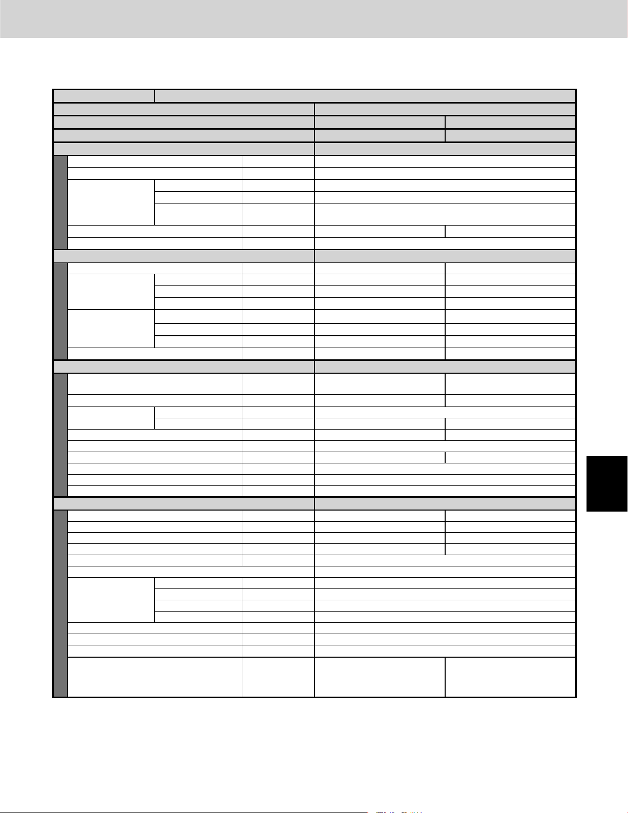
1. Outdoor Unit
3WAY VRF SYSTEM Unit Specifi cations
Unit Specifi cations (4)
MODEL NAME
GENERAL MODEL No.
COMPONENT OUTDOOR UNIT
SOURCE
PERFORMANCE
Cooling capacity BTU / h (kW) 168,000 (49.2)
Heating capacity BTU / h (kW) 189,000 (55.4)
Height in. (mm) 82-9/16 (2097)
UNIT DIMENSIONS
Net weight lbs. (kg) 573 (260) 672 (305)
Color (Munsell code) Silky shade (1Y 8.5 / 0.5)
ELECTRICAL RATINGS
Voltage rating V 208 230
Cooling
Heating
Starting amperes A 157 152
COMPRESSOR
Type - Q'ty
Motor output kW 4.1 2.7 + 3.75
Refrigeration oil
Crankcase heater W 25 25 + 32
Capacity control % –
Refrigerant amount at shipment lbs. (kg)
Refrigerant control
Defrost method
Heat exchanger
FAN DEVICE
Type - Q'ty Propeller fan x 1 Propeller fan x 1
Air circulation CFM 5,300 5,650
External static pressure in.WG 0 0
Motor output (No. of poles) kW 0.7/8P 0.7/8P
Protective devices High pressure switch, overcurrent (CT method)
TUBING
Refrigerant tubing
Drain port
External air temperature operation range °F Cooling: 14 ~ 113 °F (DB) Heating: -4 ~ 59 (WB)
Operation sound (Hi) dB-A 58.0 (Quiet mode: 55.0)
Primary accessories
* Outdoor unit model name ended with the letter “E”
Refer to the Section 1 “3. Salt-Air Damage Resistant Specifications.”
*1 If the tubing length (LA) is less than 16.4 feet, it is recommended that the suction tube be increased by 1 rank.
Rated conditions
Performance, electrical characteristics values and operating sound are based on JIS B8616 package A/C.
(Cooling : Indoor intake air temperature 80°F DB / 67°F WB. Outdoor intake air temperature 95°F DB.)
(Heating : Indoor intake air temperature 70°F DB. Outdoor intake air temperature 47°F DB / 43°F WB.)
Width in. (mm) 74 (1880)
Depth in. (mm)
Running amperes A 38.3 35.8
Power input kW 13.1 13.1
Power factor % 94.6 91.6
Running amperes A 41.9 39.1
Power input kW 14.4 14.4
Power factor % 95.4 92.3
Type FV68S (Ether oil)
Charge amount gal 1.40 (5.3 liters) 1.96 (7.4 liters)
Suction tube in. (mm) ø1-1/8 (ø28.58) (Brazing)
Discharge tube in. (mm) ø7/8 (ø22.22) (Brazing)
Liquid tube in. (mm) ø5/8 (ø15.88) (Brazing)
Balance tube in. (mm) ø3/8 (ø9.52) (Flare nut)
3WAY SYSTEM Capacity Control Outdoor Unit <14-Ton>
WU-168MF1U9, WU-168MF1U9E
U-72MF1U9, U-72MF1U9E* U-96MF1U9, U-96MF1U9E*
208-230V/3N/60Hz 208-230V/3N/60Hz
Ceiling dimension : 35 ~ +2-3/8
Inverter driven Rotary type x 1
R410A - 25.9 (11.8) R410A - 25.9 (11.8)
Reverse-cycle defrost, outdoor unit cycle defrost
Aluminum plate fin / Copper tube
Connection tubing
ø7/8 (ø22.22) - ø3/4 (ø19.05)
4 - 5
(890 ~ +60)
Inverter driven Rotary type x 1
+ Fixed Speed Scroll type x 1
Electronic expansion valve
–
Connection tubing
ø1-1/8 (ø28.58) - ø3/4 (ø19.05)
ø7/8 (ø22.22) - ø3/4 (ø19.05)
ø3/4 (ø19.05) - ø5/8 (ø15.88)
1
2
3
4
5
6
7
8
Page 80

1
2
3
4
5
6
7
8
1. Outdoor Unit
3WAY VRF SYSTEM Unit Specifi cations
Unit Specifi cations (5)
MODEL NAME
GENERAL MODEL No.
COMPONENT OUTDOOR UNIT
SOURCE
PERFORMANCE
Cooling capacity BTU / h (kW) 216,000 (63.3)
Heating capacity BTU / h (kW) 243,000 (71.1)
Height in. (mm) 82-9/16 (1887)
UNIT DIMENSIONS
Net weight lbs. (kg) 573 (260) 573 (260) 573 (260)
Color (Munsell code) Silky shade (1Y 8.5 / 0.5)
ELECTRICAL RATINGS
Voltage rating V 208 230
Cooling
Heating
Starting amperes A 36 34
COMPRESSOR
Type - Q'ty
Motor output kW 4.1 4.1 4.1
Refrigeration oil
Crankcase heater W 25 25 25
Capacity control % –
Refrigerant amount at shipment lbs. (kg)
Refrigerant control
Defrost method
Heat exchanger
FAN DEVICE
Type - Q'ty Propeller fan x 1 Propeller fan x 1 Propeller fan x 1
Air circulation CFM 5,300 5,300 5,300
External static pressure in.WG 0 0 0
Motor output (No. of poles) kW 0.7/8P 0.7/8P 0.7/8P
Protective devices High pressure switch, overcurrent (CT method)
TUBING
Refrigerant tubing
Drain port
External air temperature operation range °F Cooling: 14 ~ 113 °F (DB) Heating: -4 ~ 59 (WB)
Operation sound (Hi) dB-A 58.0 (Quiet mode: 55.0)
Primary accessories
* Outdoor unit model name ended with the letter “E”
Refer to the Section 1 “3. Salt-Air Damage Resistant Specifications.”
*1 If the tubing length (LA) is less than 16.4 feet, it is recommended that the suction tube be increased by 1 rank.
Rated conditions
Performance, electrical characteristics values and operating sound are based on JIS B8616 package A/C.
(Cooling : Indoor intake air temperature 80°F DB / 67°F WB. Outdoor intake air temperature 95°F DB.)
(Heating : Indoor intake air temperature 70°F DB. Outdoor intake air temperature 47°F DB / 43°F WB.)
Width in. (mm) 113 (2870)
Depth in. (mm)
Running amperes A 45.4 42.5
Power input kW 15.9 15.9
Power factor % 97.3 93.8
Running amperes A 49.5 46.4
Power input kW 17.4 17.4
Power factor % 97.4 94.0
Type FV68S (Ether oil)
Charge amount gal 1.40 (5.3 liters) 1.40 (5.3 liters) 1.40 (5.3 liters)
Suction tube in. (mm) ø1-3/8 (ø34.92) (Brazing)
Discharge tube in. (mm) ø1-1/8 (ø28.58) (Brazing)
Liquid tube in. (mm) ø5/8 (ø15.88) (Brazing)
Balance tube in. (mm) ø3/8 (ø9.52) (Flare nut)
3WAY SYSTEM Capacity Control Outdoor Unit <18-Ton>
WU-216MF1U9, WU-216MF1U9E
U-72MF1U9(E*) U-72MF1U9(E*) U-72MF1U9(E*)
208-230V/3N/60Hz 208-230V/3N/60Hz 208-230V/3N/60Hz
Ceiling dimension : 35 ~ +2-3/8
Inverter driven Rotary type x 1 Inverter driven Rotary type x 1 Inverter driven Rotary type x 1
R410A - 25.9 (11.8) R410A - 25.9 (11.8) R410A - 25.9 (11.8)
Reverse-cycle defrost, outdoor unit cycle defrost
Aluminum plate fin / Copper tube
Connection tubing
ø7/8 (ø22.22) – ø3/4 (ø19.05)
4 - 6
(890 ~ +60)
Electronic expansion valve
–
Connection tubing
ø7/8 (ø22.22) – ø3/4 (ø19.05)
Connection tubing
ø7/8 (ø22.22) – ø3/4 (ø19.05)
Page 81

1. Outdoor Unit
3WAY VRF SYSTEM Unit Specifi cations
Unit Specifi cations (6)
MODEL NAME
GENERAL MODEL No.
COMPONENT OUTDOOR UNIT
SOURCE
PERFORMANCE
Cooling capacity BTU / h (kW) 240,000 (70.3)
Heating capacity BTU / h (kW) 270,000 (79.1)
Height in. (mm) 82-9/16 (2097)
UNIT DIMENSIONS
Net weight lbs. (kg) 672 (305) 573 (260) 573 (260)
Color (Munsell code) Silky shade (1Y 8.5 / 0.5)
ELECTRICAL RATINGS
Voltage rating V 208 230
Cooling
Heating
Starting amperes A 173 167
COMPRESSOR
Type - Q'ty
Motor output kW 2.7 + 3.75 4.1 4.1
Refrigeration oil
Crankcase heater W 25 + 32 25 25
Capacity control % –
Refrigerant amount at shipment lbs. (kg)
Refrigerant control
Defrost method
Heat exchanger
FAN DEVICE
Type - Q'ty Propeller fan x 1 Propeller fan x 1 Propeller fan x 1
Air circulation CFM 5,650 5,300 5,300
External static pressure in.WG 0 0 0
Motor output (No. of poles) kW 0.7/8P 0.7/8P 0.7/8P
Protective devices High pressure switch, overcurrent (CT method)
TUBING
Refrigerant tubing
Drain port
External air temperature operation range °F Cooling: 14 ~ 113 °F (DB) Heating: -4 ~ 59 (WB)
Operation sound (Hi) dB-A 58.0 (Quiet mode: 55.0)
Primary accessories
* Outdoor unit model name ended with the letter “E”
Refer to the Section 1 “3. Salt-Air Damage Resistant Specifications.”
*1 If the tubing length (LA) is less than 16.4 feet, it is recommended that the suction tube be increased by 1 rank.
Rated conditions
Performance, electrical characteristics values and operating sound are based on JIS B8616 package A/C.
(Cooling : Indoor intake air temperature 80°F DB / 67°F WB. Outdoor intake air temperature 95°F DB.)
(Heating : Indoor intake air temperature 70°F DB. Outdoor intake air temperature 47°F DB / 43°F WB.)
Width in. (mm) 113 (2870)
Depth in. (mm)
Running amperes A 53.4 49.9
Power input kW 18.4 18.4
Power factor % 95.4 92.2
Running amperes A 58.4 54.6
Power input kW 20.2 20.2
Power factor % 95.9 92.8
Type FV68S (Ether oil)
Charge amount gal 1.96 (7.4 liters) 1.40 (5.3 liters) 1.40 (5.3 liters)
Suction tube in. (mm) ø1-3/8 (ø34.92) (Brazing)
Discharge tube in. (mm) ø1-1/8 (ø28.58) (Brazing)
Liquid tube in. (mm) ø3/4 (ø19.05) (Brazing)
Balance tube in. (mm) ø3/8 (ø9.52) (Flare nut)
3WAY SYSTEM Capacity Control Outdoor Unit <20-Ton>
WU-240MF1U9, WU-240MF1U9E
U-96MF1U9(E*) U-72MF1U9(E*) U-72MF1U9(E*)
208-230V/3N/60Hz 208-230V/3N/60Hz 208-230V/3N/60Hz
Ceiling dimension : 35 ~ +2-3/8
Inverter driven Rotary type x 1
+ Fixed Speed Scroll type x 1
R410A - 25.9 (11.8) R410A - 25.9 (11.8) R410A - 25.9 (11.8)
Reverse-cycle defrost, outdoor unit cycle defrost
Aluminum plate fin / Copper tube
Connection tubing
ø1-1/8 (ø28.58) - ø3/4 (ø19.05)
ø7/8 (ø22.22) - ø3/4 (ø19.05)
ø3/4 (ø19.05) - ø5/8 (ø15.88)
4 - 7
(890 ~ +60)
Inverter driven Rotary type x 1 Inverter driven Rotary type x 1
Electronic expansion valve
–
Connection tubing
ø7/8 (ø22.22) - ø3/4 (ø19.05)
Connection tubing
ø7/8 (ø22.22) - ø3/4 (ø19.05)
1
2
3
4
5
6
7
8
Page 82

1
2
3
4
5
6
7
8
1. Outdoor Unit
3WAY VRF SYSTEM Unit Specifi cations
Unit Specifi cations (7)
MODEL NAME
GENERAL MODEL No.
COMPONENT OUTDOOR UNIT
SOURCE
PERFORMANCE
Cooling capacity BTU / h (kW) 264,000 (77.4)
Heating capacity BTU / h (kW) 297,000 (87.0)
Height in. (mm) 82-9/16 (2097)
UNIT DIMENSIONS
Net weight lbs. (kg) 672 (305) 672 (305) 573 (260)
Color (Munsell code) Silky shade (1Y 8.5 / 0.5)
Width in. (mm) 113 (2870)
Depth in. (mm)
ELECTRICAL RATINGS
Voltage rating V 208 230
Running amperes A 61.5 57.3
Cooling
Heating
Starting amperes A 182 175
Power input kW 20.8 20.8
Power factor % 93.9 91.1
Running amperes A 67.3 62.8
Power input kW 23.0 23.0
Power factor % 94.9 91.9
COMPRESSOR
Type - Q'ty
Motor output kW 2.7 + 3.75 2.7 + 3.75 4.1
Refrigeration oil
Crankcase heater W 25 + 32 25 + 32 25
Capacity control % –
Refrigerant amount at shipment lbs. (kg)
Refrigerant control
Defrost method
Heat exchanger
Type FV68S (Ether oil)
Charge amount gal 1.96 (7.4 liters) 1.96 (7.4 liters) 1.40 (5.3 liters)
FAN DEVICE
Type - Q'ty Propeller fan x 1 Propeller fan x 1 Propeller fan x 1
Air circulation CFM 5,650 5,650 5,300
External static pressure in.WG 0 0 0
Motor output (No. of poles) kW 0.7/8P 0.7/8P 0.7/8P
Protective devices High pressure switch, overcurrent (CT method)
TUBING
Suction tube in. (mm) ø1-3/8 (ø34.92) (Brazing)
Refrigerant tubing
Drain port
External air temperature operation range °F Cooling: 14 ~ 113 °F (DB) Heating: -4 ~ 59 (WB)
Operation sound (Hi) dB-A 58.0 (Quiet mode: 55.0)
Primary accessories
* Outdoor unit model name ended with the letter “E”
Refer to the Section 1 “3. Salt-Air Damage Resistant Specifications.”
*1 If the tubing length (LA) is less than 16.4 feet, it is recommended that the suction tube be increased by 1 rank.
Rated conditions
Performance, electrical characteristics values and operating sound are based on JIS B8616 package A/C.
(Cooling : Indoor intake air temperature 80°F DB / 67°F WB. Outdoor intake air temperature 95°F DB.)
(Heating : Indoor intake air temperature 70°F DB. Outdoor intake air temperature 47°F DB / 43°F WB.)
Discharge tube in. (mm) ø1-1/8 (ø28.58) (Brazing)
Liquid tube in. (mm) ø3/4 (ø19.05) (Brazing)
Balance tube in. (mm) ø3/8 (ø9.52) (Flare nut)
3WAY SYSTEM Capacity Control Outdoor Unit <22-Ton>
WU-264MF1U9, WU-264MF1U9E
U-96MF1U9(E*) U-96MF1U9(E*) U-72MF1U9(E*)
208-230V/3N/60Hz 208-230V/3N/60Hz 208-230V/3N/60Hz
Ceiling dimension : 35 ~ +2-3/8
Inverter driven Rotary type x 1
+ Fixed Speed Scroll type x 1
R410A - 25.9 (11.8) R410A - 25.9 (11.8) R410A - 25.9 (11.8)
Reverse-cycle defrost, outdoor unit cycle defrost
Aluminum plate fin / Copper tube
Connection tubing
ø1-1/8 (ø28.58) - ø3/4 (ø19.05)
ø7/8 (ø22.22) - ø3/4 (ø19.05)
ø3/4 (ø19.05) - ø5/8 (ø15.88)
4 - 8
(890 ~ +60)
Inverter driven Rotary type x 1
+ Fixed Speed Scroll type x 1
Electronic expansion valve
–
Connection tubing
ø1-1/8 (ø28.58) - ø3/4 (ø19.05)
ø7/8 (ø22.22) - ø3/4 (ø19.05)
ø3/4 (ø19.05) - ø5/8 (ø15.88)
Inverter driven Rotary type x 1
Connection tubing
ø7/8 (ø22.22) - ø3/4 (ø19.05)
Page 83

1. Outdoor Unit
3WAY VRF SYSTEM Unit Specifi cations
Unit Specifi cations (8)
MODEL NAME
GENERAL MODEL No.
COMPONENT OUTDOOR UNIT
SOURCE
PERFORMANCE
Cooling capacity BTU / h (kW) 288,000 (84.4)
Heating capacity BTU / h (kW) 324,000 (94.9)
Height in. (mm) 82-9/16 (2097)
UNIT DIMENSIONS
Net weight lbs. (kg) 672 (305) 672 (305) 672 (305)
Color (Munsell code) Silky shade (1Y 8.5 / 0.5)
Width in. (mm) 113 (2870)
Depth in. (mm)
ELECTRICAL RATINGS
Voltage rating V 208 230
Running amperes A 69.5 64.7
Cooling
Heating
Starting amperes A 191 183
Power input kW 23.3 23.3
Power factor % 92.8 90.2
Running amperes A 76.2 71.0
Power input kW 25.8 25.8
Power factor % 94.0 91.2
COMPRESSOR
Type - Q'ty
Motor output kW 2.7 + 3.75 2.7 + 3.75 2.7 + 3.75
Refrigeration oil
Crankcase heater W 25 + 32 25 + 32 25 + 32
Capacity control % –
Refrigerant amount at shipment lbs. (kg)
Refrigerant control
Defrost method
Heat exchanger
Type FV68S (Ether oil)
Charge amount gal 1.96 (7.4 liters) 1.96 (7.4 liters) 1.96 (7.4 liters)
FAN DEVICE
Type - Q'ty Propeller fan x 1 Propeller fan x 1 Propeller fan x 1
Air circulation CFM 5,650 5,650 5,650
External static pressure in.WG 0 0 0
Motor output (No. of poles) kW 0.7/8P 0.7/8P 0.7/8P
Protective devices High pressure switch, overcurrent (CT method)
TUBING
Suction tube in. (mm) ø1-3/8 (ø34.92) (Brazing)
Refrigerant tubing
Drain port
External air temperature operation range °F Cooling: 14 ~ 113 °F (DB) Heating: -4 ~ 59 (WB)
Operation sound (Hi) dB-A 58.0 (Quiet mode: 55.0)
Primary accessories
* Outdoor unit model name ended with the letter “E”
Refer to the Section 1 “3. Salt-Air Damage Resistant Specifications.”
*1 If the tubing length (LA) is less than 16.4 feet, it is recommended that the suction tube be increased by 1 rank.
Rated conditions
Performance, electrical characteristics values and operating sound are based on JIS B8616 package A/C.
(Cooling : Indoor intake air temperature 80°F DB / 67°F WB. Outdoor intake air temperature 95°F DB.)
(Heating : Indoor intake air temperature 70°F DB. Outdoor intake air temperature 47°F DB / 43°F WB.)
Discharge tube in. (mm) ø1-1/8 (ø28.58) (Brazing)
Liquid tube in. (mm) ø3/4 (ø19.05) (Brazing)
Balance tube in. (mm) ø3/8 (ø9.52) (Flare nut)
3WAY SYSTEM Capacity Control Outdoor Unit <24-Ton>
WU-288MF1U9, WU-288MF1U9E
U-96MF1U9(E*) U-96MF1U9(E*) U-96MF1U9(E*)
208-230V/3N/60Hz 208-230V/3N/60Hz 208-230V/3N/60Hz
Ceiling dimension : 35 ~ +2-3/8
Inverter driven Rotary type x 1
+ Fixed Speed Scroll type x 1
R410A - 25.9 (11.8) R410A - 25.9 (11.8) R410A - 25.9 (11.8)
Reverse-cycle defrost, outdoor unit cycle defrost
Aluminum plate fin / Copper tube
Connection tubing
ø1-1/8 (ø28.58) - ø3/4 (ø19.05)
ø7/8 (ø22.22) - ø3/4 (ø19.05)
ø3/4 (ø19.05) - ø5/8 (ø15.88)
4 - 9
(890 ~ +60)
Inverter driven Rotary type x 1
+ Fixed Speed Scroll type x 1
Electronic expansion valve
–
Connection tubing
ø1-1/8 (ø28.58) - ø3/4 (ø19.05)
ø7/8 (ø22.22) - ø3/4 (ø19.05)
ø3/4 (ø19.05) - ø5/8 (ø15.88)
Inverter driven Rotary type x 1
+ Fixed Speed Scroll type x 1
Connection tubing
ø1-1/8 (ø28.58) - ø3/4 (ø19.05)
ø7/8 (ø22.22) - ø3/4 (ø19.05)
ø3/4 (ø19.05) - ø5/8 (ø15.88)
1
2
3
4
5
6
7
8
Page 84

1. Outdoor Unit
1-2. AHRI Registration Values
3WAY VRF SYSTEM Unit Specifi cations
1
2
Outdoor Unit
Models
U-72MF1U9(E)
U-96MF1U9(E)
WU-144MF1U9(E)
WU-168MF1U9(E)
WU-216MF1U9(E)
Indoor Unit
Types
Ducted
Non Ducted
Mixed Non-Ducted and Duced
Ducted
Non Ducted
Mixed Non-Ducted and Duced
Ducted
Non Ducted
Mixed Non-Ducted and Duced
Ducted
Non Ducted
Mixed Non-Ducted and Duced
Ducted
Non Ducted
Cooling
Capacity
BTU/h 95°F
72,000 81,000 47,00011.4 3.50 2.2816.4
198,000 220,000 120,00010.5 3.21 2.0516.6
EER IEER
HI
Heating
Capacity
BTU/h
HI COP
47°F
Low
Heating
Capacity
BTU/h
Low COP SCHE
17°F
24.0
24.769,000 77,000 42,00010.9 3.31 2.2517.1
24.471,000 79,500 44,50011.2 3.41 2.2716.8
23.195,000 106,000 69,00011.0 3.30 2.2516.0
23.593,000 103,000 58,50010.9 3.31 2.2516.7
23.394,000 104,500 63,50011.0 3.31 2.2516.4
23.1138,000 156,000 93,00010.8 3.21 2.0516.4
23.8136,000 150,000 83,00010.9 3.31 2.2517.1
23.5137,000 153,000 88,00010.9 3.26 2.1516.8
22.6164,000 184,000 114,00010.7 3.21 2.0516.1
23.3160,000 178,000 98,00010.5 3.21 2.0516.9
23.0162,000 181,000 106,00010.6 3.21 2.0516.5
22.2202,000 228,000 136,00010.6 3.21 2.0516.0
22.9
3
4
5
6
7
WU-240MF1U9(E)
WU-264MF1U9(E)
WU-288MF1U9(E)
Mixed Non-Ducted and Duced
Ducted
Non Ducted
Mixed Non-Ducted and Duced
Ducted
Non Ducted
Mixed Non-Ducted and Duced
Ducted
Non Ducted
Mixed Non-Ducted and Duced
220,000 246,000 136,00010.5 3.21 2.0516.4
252,000 268,000 150,0009.4 3.21 2.0516.3
274,000 292,000 164,0009.4 3.21 2.0516.2
22.6200,000 224,000 128,00010.6 3.21 2.0516.3
22.0230,000 264,000 158,00010.5 3.21 2.0516.0
22.4
22.2225,000 255,000 147,00010.5 3.21 2.0516.2
21.6258,000 288,000 176,0009.7 3.21 2.0515.9
22.0
21.8255,000 278,000 163,0009.6 3.21 2.0516.1
21.2280,000 312,000 194,0009.6 3.21 2.0515.8
21.6
21.4277,000 302,000 179,0009.5 3.21 2.0516.0
8
4 - 10
Page 85

1. Outdoor Unit
1-3. Dimensional Data
U-72MF1U9, U-72MF1U9E, U-96MF1U9, U-96MF1U9E
U-72MF1U9
U-72MF1U9E
(6-Ton) (8-Ton)
3/4" (
ø
1
Refrigerant tube (gas tube)
2
Refrigerant tube (discharge tube)
3
Refrigerant tube (liquid tube)
4
Refrigerant tube (balance tube)
5
Installation holes (4 –19/32" × 25/32" elongated holes), anchor bolts M12 or 15/32" or larger
6
Refrigerant port (front: knock-out hole and slit)
7
Refrigerant port (bottom: slit hole)
8
Electrical wiring port (front: ø2-23/64", ø1-7/64" knock-out holes – for conduit connection)
9
Electrical wiring port (bottom:ø2-23/64", ø1-1/2" knock-out holes – for conduit connection)
10
Pressure outlet port (for high pressure: ø5/16" (ø7.94) Schrader-type connection)
11
Pressure outlet port (for low pressure: ø5/16" (ø7.94) Schrader-type connection)
12
Knock-out hole for connecting pressure gauge (optional)
brazed connection
brazed connection
brazed connection
flared connection
19.05)
5/8" (ø15.88) 3/4" (ø19.05)
3/8" (ø9.52) 3/8" (ø9.52)
ø
9.52) 3/8" (ø9.52)
3/8" (
unit : in.(mm)
U-96MF1U9
U-96MF1U9E
7/8" (ø22.22)
3WAY VRF SYSTEM Unit Specifi cations
Air
intake
Air
intake
31-1/8
(Installation hole pitch)
(Ceiling panel dimensions)
Air
intake
35
Air
discharge
Air
intake
5
35
(Ceiling panel dimensions)
Top view
unit : in.
37-1/2
36-1/4
(Installation hole pitch)
(Maximum dimensions)
10
3
4
2
11
1
c
b
a
13-37/64
1-31/32
d
e
f
9-61/64
Position of refrigerant
connection
Position of
installation
(Knock-out hole)
1-1/2
(Knock-out hole)
Left side
2-23/64
9
37-13/32
(Bottom plate dimension)
34-9/64
(Bottom plate dimension)
Z view
(8-1/2)
82-9/16
74-1/16
31-19/64
6-59/64
Space for creation of hole on-site
(Max. diameter
17-51/64
14-1/4
9-1/16
7
13/64
ø1-57/64)
5-1/8
4-39/64
3-15/16
Table of Measurements for Refrigerant Tube Connection
Equivalent
tonnage
6-Ton
1-31/32
A
8-Ton
*
Measurements for 8-Ton assume that the supplied
connection tubing is used.
4 - 11
6-11/32
Z
8
Front view
1-31/32
mounting surface
Installation bracket
(1-33/64)
Enlarged view of A
abcde
10-25/32
10-1/8
(257)
6-37/64
(167)
(274)
6-27/32
(174)
13-5/16
18-5/8
2-11/64
8-47/64
(19/32)
Size in. (mm)
12-29/32
(328)
12-29/32
(328)
12
6
2-29/32
3-35/64
(90)
3-35/64
(90)
4-39/64
5-63/64
(152)
5-63/64
(152)
f
8-17/64
(210)
8-17/64
(210)
1
2
3
4
5
6
7
8
Page 86

1. Outdoor Unit
3WAY VRF SYSTEM Unit Specifi cations
1
1-4. Multiple Unit Installation Example
Equivalent
tonnage
12-Ton
14-Ton
6-Ton
U-72MF1U9
U-72MF1U9E
8-Ton
U-96MF1U9
U-96MF1U9E
-
(8-1/2)
82-9/16
74-1/16
74 (Ceiling panel dimensions)
(Ceiling panel dimensions)
35
31-1/8
(Installation hole pitch)
(Installation hole pitch)
70-1/8
4
(Ceiling panel dimensions)
7-7/8
35
31-1/8
(Installation hole pitch)
35
36-1/4
(Ceiling panel dimensions)
Top view
37-1/2
(Installation hole pitch)
(Maximum dimensions)
unit: in.
2
3
4
5
6
Equivalent
tonnage
18-Ton
20-Ton
22-Ton
24-Ton
6-Ton
U-72MF1U9
U-72MF1U9E
-
31-19/64
Left side Right sideFront view
113 (Ceiling panel dimensions)
8-Ton
U-96MF1U9
U-96MF1U9E
-
(8-1/2)
(Ceiling panel dimensions)
35
(Installation hole pitch)
7-7/8 7-7/831-1/8
109-1/16 (Installation hole pitch)
44
(Ceiling panel dimensions)
35
31-1/8
(Installation hole pitch)
(Ceiling panel dimensions)
35
31-1/8
(Installation hole pitch)
35
36-1/4
(Ceiling panel dimensions)
Top view
37-1/2
(Installation hole pitch)
(Maximum dimensions)
7
8
82-9/16
74-1/16
31-19/64
Left side Right sideFront view
4 - 12
Page 87
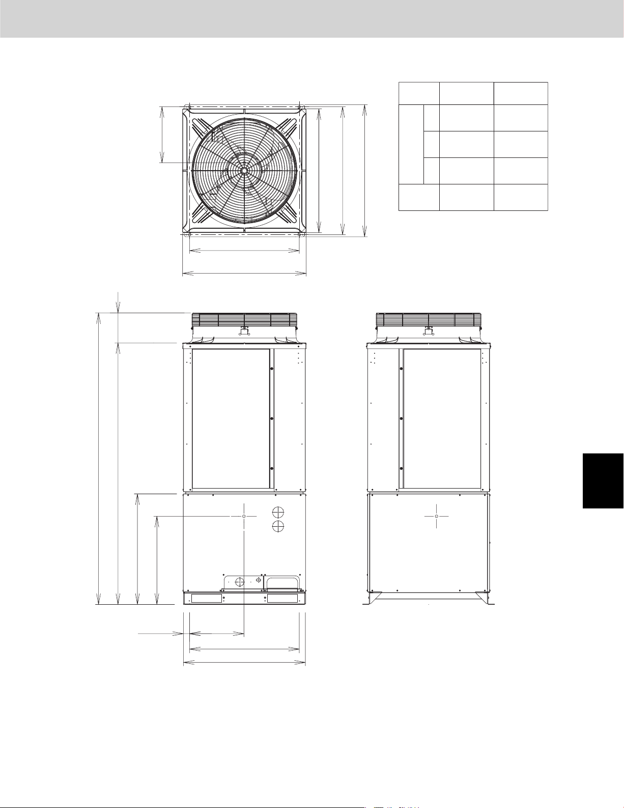
1. Outdoor Unit
Position of center
of gravity
Y
3WAY VRF SYSTEM Unit Specifi cations
MODEL
35
(Ceiling panel dimensions)
37-1/2
36-1/4
(Installation hole pitch)
(Maximum dimensions)
Position of center
Weight
lbs (kg)
X
in. (mm)
Y
Z
of gravity
U-72MF1U9
U-72MF1U9E
15-3/8
(392)
17-3/4
(452)
33-5/8
(853)
573
(260)
U-96MF1U9
U-96MF1U9E
13-1/4
(336)
18-7/8
(481)
30-1/4
(767)
683
(310)
(8-1/2)
82-9/16
74-1/16
31-1/8
(Installation hole pitch)
35
(Ceiling panel dimensions)
Top view
1
2
3
4
Z
31-19/64
1-47/64
X
31-7/64
34-9/16
Front view
4 - 13
Right side
unit : in.
5
6
7
8
Page 88

1
1. Outdoor Unit
1-5. Refrigerant Flow Diagram
U-72MF1U9, U-72MF1U9E
Solenoid
valve
Oil separator
Oil drain
High pressure switch
S
Solenoid
valve
S
HP
Solenoid valve
S
4-way
valve
Solenoid
valve
S
S
S
S
4-way
valve
Solenoid
valve
3WAY VRF SYSTEM Unit Specifi cations
LPS
Low pressure sensor
To be brazed pinch
after oil is inserted. (1 portion)
Accumulator
S
HPS
High Pressure sensor
S
Fusible
plug
S
Thermistor position
Strainer
For LP
For HP
Balance tube
ø3/8" flare connection
Suction tube
ø3/4" Brazing
Discharge tube
ø5/8" Brazing
Narrow tube
ø3/8" Brazing
2
3
4
5
6
7
Outside air
Electronic
control valv
U-96MF1U9, U-96MF1U9E
High pressure switch
Solenoid
valve
Oil separator
Oil drain
S
Solenoid
valve
Outside air
M
e
M
Electronic control valve
HP
HP
Solenoid valve
S
S
4-way
S
valve
Solenoid
valve
S
4-way
valve
Solenoid
valve
Fusible
plug
M
LPS
Low pressure sensor
o be brazed pinch
T
after oil is inserted. (1 portion)
Accumulator
S
S
S
HPS
High Pressure sensor
Thermistor position
Strainer
For LP
For HP
Balance tube
ø3/8" flare connection
Suction tube
ø7/8" Brazing (Use supplied only)
Discharge tube
ø3/4" Brazing (Use supplied only)
Narrow tube
S
S
Fusible
plug
ø3/8" Brazing
8
Electronic
control valve
Fusible
M
M
M
plug
Electronic control valve
4 - 14
Page 89

1. Outdoor Unit
1-6. Noise Criterion Curves
3WAY VRF SYSTEM Unit Specifi cations
MODEL
SOUND LEVEL
dB(A)
(Cooling/Heating)
CONDITION
70
60
50
40
30
Approximate
minimum audible
limit for continuous
noise
20
Overall
Octave Band Level (dB)
63 125 250 500 1000 2000 4000 8000
U-72MF1U9, U-72MF1U9E
54.5
(Quiet mode 51.5)
3.3 ft front at height of 4.9 ft
Frequency at center of octave band (Hz)
60Hz
Standard mode
Quiet mode
MODEL
SOUND LEVEL
dB(A)
(Cooling/Heating)
CONDITION
70
60
50
40
30
Approximate
minimum audible
limit for continuous
noise
20
Overall
Octave Band Level (dB)
63 125 250 500 1000 2000 4000 8000
U-96MF1U9, U-96MF1U9E
55.0
(Quiet mode 52.0)
3.3 ft in front at height of 4.9 ft
Frequency at center of octave band (Hz)
60Hz
Standard mode
Quiet mode
1
2
3
4
5
6
7
4 - 15
8
Page 90

– MEMO –
4 - 16
Page 91

Test Run
Contents
5. TEST RUN
1. Preparing for Test Run .......................................................................................................5-2
2. Test Run Procedure ............................................................................................................5-3
3. Main Outdoor Unit PCB Setting.........................................................................................5-4
4. Auto Address Setting .........................................................................................................5-6
5. Remote Controller Test Run Settings .............................................................................5-12
6. Caution for Pump Down ...................................................................................................5-12
7. Meaning of Alarm Messages ...........................................................................................5-13
1
2
3
4
5
6
5 - 1
7
8
Page 92

1
2
3
1. Preparing for Test Run
1. Preparing for Test Run
Before attempting to start the air conditioner, check the fol-
z
lowing.
(1) The control wiring is correctly connected and all electrical
connections are tight.
(2) The transportation pads for the indoor fan have been
removed. If not, remove them now.
(3) The power has been connected to the unit for at least 5
hours before starting the compressor. The bottom of the
compressor should be warm to the touch and the crankcase heater around the feet of the compressor should be
hot to the touch.
(Fig. 5-1)
(4) If only 1 outdoor unit is installed, close the service valve
on the balance tubes, and open the service valve on the
other 3 tubes (suction, discharge, and liquid tubes). (Fig.
5-2)
If 2 or 3 outdoor units are installed, open the service
valves on all 4 tubes (suction, discharge, liquid, and balance tubes). (Fig. 5-2)
(5) Request that the customer be present for the trial run.
Explain the contents of the instruction manual, then have
the customer actually operate the system.
(6) Be sure to give the instruction manual and warranty cer-
tifi cate to the customer.
(7) When replacing the control PCB, be sure to make all the
same settings on the new PCB as were in use before
replacement.
The existing EEP ROM is not changed, and is connected
to the new control PCB.
Power mains switch
Balance tube
Liquid tube
Discharge tube
Test Run
ON
(Power must be turned ON
at least 5 hours before
attempting test run)
Fig. 5-1
Suction tube
4
5
6
7
8
Fig. 5-2
5 - 2
Page 93

2. Test Run Procedure
2. Test Run Procedure
Test Run
Recheck the items to check before the test run.
<Outdoor unit control PCB>
Unit No. setting switch
(S007)
<Outdoor unit control PCB>
Unit No. setting switch
(S006)
<Outdoor unit control PCB>
Unit No. setting switch
(S004 and S005)
(Check the link wiring.)
<Outdoor unit control PCB>
Unit No. setting switch
(S002 and S003)
Refer to Fig. 5-4
Is it OK to start the compressors?
Turn ON the indoor and
*2
(CN101) on the outdoor main unit PCB.
*3 *3
outdoor unit power.
Short-circuit the mode change pin
At the same time, short-circuit the
automatic address pin (CN100) for 1
second or longer, then release it.
Start indoor and outdoor unit
cooling operation.
LED 1 and 2 blink alternately.
When multiple outdoor main units exist, disconnect the terminals
extended from the shorted plugs (CN003) at all outdoor main unit
PCBs except for 1. Alternatively, move the sockets to the OPEN side.
NO
CASE 3B CASE 3A
Are LEDs 1 and 2 on the
outdoor unit PCB OFF?
Set the No. of outdoor units.
Set the No. of indoor units.
inter-unit control wires connected
to more than 1 refrigerant
Set the system address.
to turn ON the power only for the 1 refrigerant
system where the test run will be
Will automatic address setting
be performed in Heating mode?
Have the outdoor sub
units been connected?
YES
Set the unit address.
*1 The unit with the unit No. set to 1 is
the main unit. All other units are sub
units.
Are the
system?
YES
Is it possible
performed?
YES
Is it OK to start the compressors?
Turn ON the indoor and
outdoor unit power.
*2
Short-circuit the automatic
address pin (CN100) on the
outdoor main unit PCB for
1 second or longer,
then release it.
Start indoor and outdoor unit
heating operation.
LED 1 and 2 blink alternately.
NO
YES
*1
NO
NO
CASE 1
NO
Note: It is not necessary to remove
CASE 2
YES
Make necessary corrections.
Turn OFF the indoor and
outdoor unit power.
Check the alarm contents.
Make necessary
corrections
Refer to Table of Self-Diagnostic
Functions and Description of Alarm Displays.
Turn OFF the indoor
and outdoor unit power.
Check the alarm
contents.
A minimum of 5 hours must have passed after
*2
the power was turned ON to the outdoor unit.
*3 All indoor units operate in all refrigerant
systems where the power is ON.
Items to Check Before the Test Run
1. Turn the remote power switch on at
least 5 hours before the test, in order to
energize the crankcase heater.
2. Turn the outdoor service valves
(4 locations) to the full-open positions.
Use caution when making the settings.
If there are duplicated system addresses,
or if the settings for the Nos. of the indoor
units are not consistent, an alarm will
occur and the system will not start.
These settings are not made on the
indoor unit PCB.
the socket that is used to
short-circuit the terminal plugs
from the outdoor sub unit
PCBs.
Turn ON the indoor and outdoor unit power
for that refrigerant system only.
Short-circuit the automatic address
pin (CN100) on the outdoor main unit PCB
for 1 second or longer, then release it.
LED 1 and 2 blink alternately
(about 2 or 3 minutes).
NO
Are LEDs 1 and 2 on the
outdoor unit PCB OFF?
YES
1
2
3
4
5
6
(Do not allow the short-circuited pins to remain short-circuited.)
Refer to the remote
controller test-run
settings.
Check that test run preparation is OK.
Set the wired remote controller for test run.
Does system operate?
YES
Return remote control to normal mode
NO
Check and make corrections according
to Table of Self-Diagnostic Functions.
5 - 3
Fig. 5-3
7
8
Page 94

1
2
3. Main Outdoor Unit PCB Setting
3. Main Outdoor Unit PCB Setting
L Examples of the No. of indoor units settings (S005, S004)
No. of indoor units
1 unit (factory setting)
11 units
21 units
31 units
40 units
Indoor unit setting (S005)
(3P DIP switch, blue)
All OFF
1 ON
2 ON
3 ON
1 & 3 ON
10 20 30
ON
1
ON
1
ON
1
ON
1
ON
1
ON
3
2
OFF
ON
3
2
OFF
ON
3
2
OFF
ON
3
2
OFF
ON
3
2
OFF
L Examples of refrigerant circuit (R.C.) address settings (required when link wiring is used) (S003, S002)
System address (S003)
System address No.
System 1 (factory setting)
System 11
System 21
System 30
(2P DIP switch, blue)
10 20
1 ON
2 ON
ON
2
1
ON
2
1
ON
2
1
ON
2
1
Both OFF
1 & 2 ON
Indoor unit setting (S004)
(Rotary switch, red)
1
Set to 1
1
Set to 1
1
Set to 1
1
Set to 1
0
Set to 0
System address (S002)
(Rotary switch, black)
ON
OFF
ON
OFF
ON
OFF
ON
OFF
1
1
1
0
Set to 1
Set to 1
Set to 1
Set to 0
Test Run
3
4
5
6
7
L Examples of the No. of outdoor units settings (S006)
No. of outdoor units
1 unit (factory setting)
2 units
3 units
Outdoor unit setting (S006)
(3P DIP switch, blue)
ON
1 ON
2 ON
1 & 2 ON
1
ON
12
ON
1
2
2
ON
3
OFF
ON
3
OFF
ON
3
OFF
L Address setting of main outdoor unit (S007)
Unit No. setting
Unit No. 1 (main unit)
Address setting of outdoor unit (S007)
(3P DIP switch, blue)
ON
21ON3
OFF
L Address setting of sub outdoor unit
Unit No. setting
Unit No. 2 (sub unit)
Unit No. 3 (sub unit)
Address setting of outdoor unit (S007)
(3P DIP switch, blue)
ON
2 ON
12
ON
1 & 2 ON
21
ON
3
OFF
ON
3
OFF
The sub unit control PCB contains the same switches as the main unit control PCB for No. of indoor units, No. of outdoor units,
and system address. However it is not necessary to set these switches.
8
5 - 4
Page 95

3. Main Outdoor Unit PCB Setting
Test Run
1
CN003
CN101
CN100
2
3
4
5
6
Fig. 5-4
5 - 5
7
S002S003S004S005S007 S006
8
Page 96

1
4. Auto Address Setting
4. Auto Address Setting
Basic wiring diagram: Example (1)
• If link wiring is not used (The inter-unit control wires are not connected to multiple refrigerant systems.)
Indoor unit addresses can be set without operating the compressors.
No. 1 (main outdoor unit)
settings
System address
(system 1 setting)
(S003)(S002)
ON
1
No. of
outdoor
units (3 units
setting)
ON
2
1
OFF
(S006) (S007)
ON
1
Outdoor Unit
2
3
OFF
Unit number
ON
setting
(Unit No. 1)
Unit
No. 1
(Main)
No. of indoor units
(10 units setting)
(S004)
0
(S005)
ON
1ON3
2
OFF
ON
ON
1
2
3
OFF
Leave the socket that
is used to short-circuit
the terminal plug.
(CN003)
Inter-outdoor unit
control wiring
Inter-unit control wiring
No. 2 (sub unit)
Unit
number
setting
(Unit No. 2)
(S007)
ON
123
Unit
No. 2
(Sub)
ON
OFF
Inter-outdoor unit
control wiring
Unit
number
setting
(Unit No. 3)
No. 3 (sub unit)
(S007)
ON
2
1
3
Unit
No. 3
(Sub)
Test Run
ON
OFF
2
3
4
5
6
Case 1
Indoor Unit
Remote controller
1-1
1-2
1-3
Remote control
communication wiring
1-10
Fig. 5-5
(1) Automatic Address Setting from the Outdoor Unit
1. To set the number of outdoor units, on the outdoor main unit control PCB set the No. of outdoor units DIP switch (S006) to
ON
123
On the No. 2 (sub) unit control PCB, set the unit No. switch (S007) to
2.
ON
(3 units), and set the unit No. DIP switch (S007) to (unit No. 1 - main outdoor unit).
OFF
On the No. 3 (sub) unit control PCB, set the unit No. switch (S007) to
3.
On the outdoor main unit control PCB, check that the system address rotary switch (S002) is set to “1” and that the DIP
switch (S003) is set to
4.
To set the number of indoor units that are connected to the outdoor unit to 10 on the outdoor main unit control PCB, set the
No. of indoor units DIP switch (S005) to
Turn ON the power to the indoor and outdoor units.
5.
On the outdoor main unit control PCB, short-circuit the automatic address pin (CN100) for 1 second or longer, then release it.
6.
ON
ON
1
2
“0.” (These are the settings at the time of factory shipment.)
OFF
ON
1
ON
2
“1.” and set the rotary switch (S004) to “0.”
3
OFF
ON
1
2
3
ON
1
ON
123
3
2
(unit No. 2).
(unit No. 3).
7
8
(Communication for automatic address setting begins.)
To cancel, again short-circuit the automatic address pin (CN100) for 1 second or longer, then release it.
*
The LED that indicates that automatic address setting is in progress turns OFF and the process is stopped.
Be sure to perform automatic address setting again.
(Automatic address setting is completed when LEDs 1 and 2 on the outdoor main unit control PCB turn OFF.)
Operation from the remote controllers is now possible.
7.
To perform automatic address setting from the remote controller, perform steps 1 to 5, then use the remote controller and
*
complete automatic address setting.
Refer to “Automatic Address Setting from the Remote Controller.”
5 - 6
Page 97
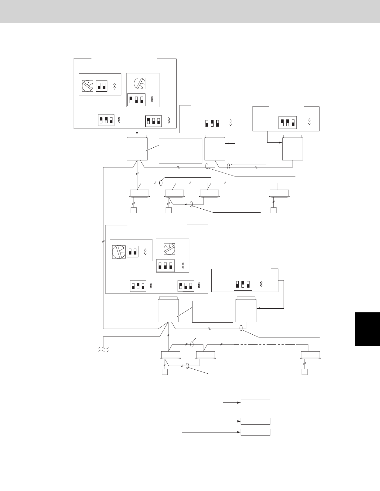
4. Auto Address Setting
Basic wiring diagram: Example (2)
No. 1 (main outdoor unit) settings
System address
(system 1 setting)
(S003)(S002)
ON
ON
1
2
1
OFF
No. of
outdoor units
(3 units
setting)
ON
(S006)
1
Unit
ON
number
2
setting
3
(unit No. 1)
OFF
•
If link wiring is used
No. of indoor units
(13 units setting)
(S004)
3
(S005)
ON
1
ON
3
2
OFF
(S007)
ON
2
3
1
ON
OFF
No. 2 (sub unit)
Unit
number
setting
(unit No. 2)
Test Run
*
When multiple outdoor main units exist, remove the socket that is
used to short-circuit the terminal plug (CN003) from all outdoor
main unit PCBs except for one unit.
Alternatively, move the sockets to the “OPEN” side.
No. 3 (sub unit)
ON
123
ON
OFF
Unit
number
setting
(unit No. 3)
(S007)(S007)
ON
2
1
ON
3
OFF
No. 2
Refrigerant
circuit
Outdoor unit
system 1
Indoor unit
Remote
controller
System address
(system 2 setting)
2
No. of
outdoor
units (2 units
setting)
Unit
No. 1
(Main)
Leave the socket that
is used to short-circuit
the terminal plug.
(CN003)
Inter-unit control wiring
No. 1 (main unit) settings
No. of indoor units
(9 units setting)
ON
OFF
(S004)
9
(S005)
2
1ON3
Unit
number
setting
(unit No. 1)
(S003)(S002)
ON
1
2
(S006)
ON
123
ON
OFF
Unit
Outdoor unit
system 2
No. 1
(Main)
ON
OFF
(S007)
ON
ON
2
3
1
OFF
Move the socket to
the “OPEN” side
(CN003).
Unit
No. 2
(Sub)
Inter-outdoor unit
control wiring
Inter-outdoor unit control wiring
Remote control
communication wiring
No. 2 (sub unit) settings
Unit
number
setting
(unit No. 2)
(S007)
ON
123
Unit
No. 2
(Sub)
Unit
No. 3
(Sub)
1
1-131-31-21-1
2
3
ON
OFF
4
Inter-unit control wiring
To other system
link wiring
Indoor unit
Remote
controller
2-1 2-2 2-9
Remote control
communication wiring
Make settings as appropriate for the cases listed below.
(Refer to the instructions on the following pages.)
· Indoor and outdoor unit power can be turned ON for each system separately.
· Indoor and outdoor unit power cannot be turned ON for each system separately.
Automatic address setting in Heating mode
Automatic address setting in Cooling mode
Fig. 5-6
5 - 7
Inter-outdoor unit control wiring
Case 2
Case 3A
Case 3B
5
6
7
8
Page 98

4. Auto Address Setting
Test Run
1
Case 2
Automatic Address Setting from Outdoor Unit
1.
2.
3.
Automatic Address Setting (no compressor operation)
Indoor and outdoor unit power can be turned ON for each system separately.
Indoor unit addresses can be set without operating the compressors.
ON
On the No. 1 (main) unit control PCB, set the unit No. switch (S007) to
On the No. 2 (sub) unit control PCB, set the unit No. switch (S007) to
On the No. 3 (sub) unit control PCB, set the unit No. switch (S007) to
To set the number of outdoor units on the outdoor main unit control PCB, set the No. of outdoor units DIP switch (S006) to
ON
123
On the outdoor main unit control PCB, check that the system address rotary switch (S002) is set to “1” and that the DIP
switch (S003) is set to “0”
ON
OFF
(3 units).
ON
ON
(These are the settings at the time of factory shipment.)
1
.
2
OFF
1
ON
1
ON
1
2
3
2
3
2
(unit No. 1).
3
(unit No. 2).
(unit No. 3).
2
3
4
5
6
To set the number of indoor units that are connected to the outdoor unit to 13 on the outdoor main unit control PCB, set the
4.
ON
No. of indoor units DIP switch (S005) to “1”
5.
Turn on power to all indoor and outdoor units in the system.
6.
Short-circuit the automatic address pin at the outdoor main unit (CN100) for 1 second or longer, then release it.
(Communication for automatic address setting begins.)
*
To cancel, again short-circuit the automatic address pin (CN100) for 1 second or longer, then release it.
The LED that indicates automatic address setting is in progress turns OFF and the process is stopped.
Be sure to perform automatic address setting again.
(Automatic address setting is completed when LEDs 1 and 2 on the outdoor main unit control PCB turn OFF.)
7.
Next turn the power ON only for the indoor and outdoor units of the next (different) system. Repeat steps 1 - 5 in the same
way to complete automatic address settings for all systems.
8.
Operation from the remote controllers is now possible.
*
To perform automatic address setting from the remote controller, perform steps 1 - 5, then use the remote controller and
complete automatic address setting.
1
ON
2
, and set the rotary switch (S004) to “3.”
3
OFF
7
8
Refer to “Automatic Address Setting from Remote Controller.”
5 - 8
Page 99

4. Auto Address Setting
Case 3A Automatic Address Setting in Heating Mode
Indoor and outdoor unit power cannot be turned ON for each system separately.
z
In the following, automatic setting of indoor unit addresses is not possible if the compressors are not operating.
Therefore perform this process only after completing all refrigerant tubing work.
Automatic Address Setting from Outdoor Unit
Test Run
1. Perform steps 1 - 4 in the same way as for
5. Turn the indoor and outdoor unit power ON at all systems.
6. To perform automatic address setting in Heating mode , on the outdoor main unit control PCB in the refrigerant system
where you wish to set the addresses, short-circuit the automatic address pin (CN100) for 1 second or longer, then release
it. (Be sure to perform this process for one system at a time. Automatic address settings cannot be performed for more than
one system at the same time.)
(Communication for automatic address setting begins, the compressors turn ON, and automatic address setting in
Heating mode begins.)
(All indoor units operate.)
* To cancel, again short-circuit the automatic address pin (CN100) for 1 second or longer, then release it. The
LED that indicates automatic address setting is in progress turns OFF and the process is stopped. Be sure to
perform automatic address setting again.
(Automatic address setting is completed when the compressors stop and LEDs 1 and 2 on the main unit control PCB turn
OFF.)
7. At the outdoor main unit in the next (different) system, short-circuit the automatic address pin (CN100) for 1 second or
longer, then release it.
(Repeat the same steps to complete automatic address setting for all units.)
8. Operation from the remote controllers is now possible.
* To perform automatic address setting from the remote controller, perform steps 1 - 5, then use the remote controller and
complete automatic address setting.
Refer to “Automatic Address Setting from Remote Controller.”
z
Case 2
.
1
2
3
4
5 - 9
5
6
7
8
Page 100
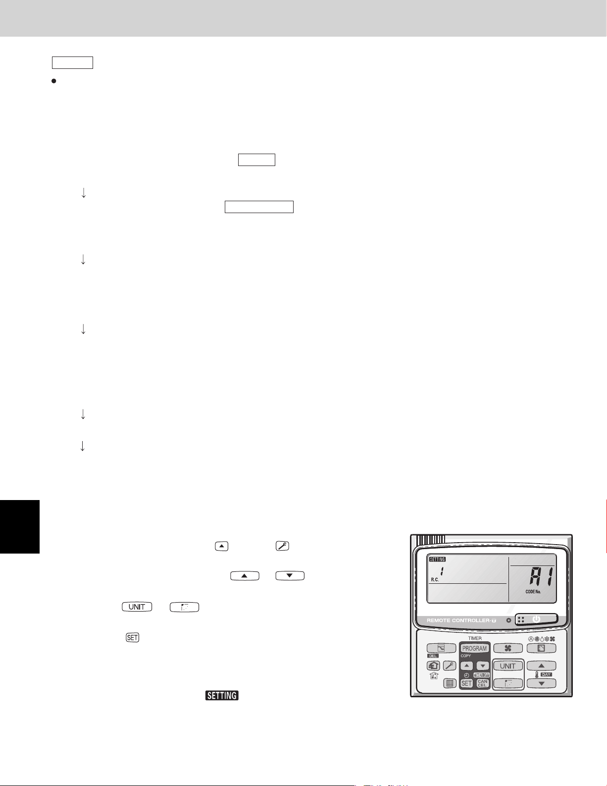
4. Auto Address Setting
Test Run
1
2
Case 3B
Indoor and outdoor unit power cannot be turned ON for each system separately.
In the following, automatic setting of indoor unit addresses is not possible if the compressors are not operating.
Therefore perform this process only after completing all refrigerant tubing work.
Automatic address setting can be performed during Cooling operation.
Automatic Address Setting from Outdoor Unit
Perform steps 1 – 4 in the same way as for .
1.
Turn the indoor and outdoor unit power ON at all systems.
5.
To perform automatic address setting in , on the outdoor main unit control PCB in the refrigerant system
6.
where you wish to set the addresses, short-circuit the mode change 2P pin (CN101). At the same time, short-circuit the
automatic address pin (CN100) for 1 second or longer, then release it. (Be sure to perform this process for one system at
a time. Automatic address settings cannot be performed for more than one system at the same time.)
(Communication for automatic address setting begins, the compressors turn ON, and automatic address setting in
Cooling mode begins.)
(All indoor units operate.)
(Automatic address setting is completed when the compressors stop and LEDs 1 and 2 on the outdoor main unit control
PCB turn OFF.)
Automatic Address Setting in Cooling Mode
Case 2
Cooling mode
To cancel, again short-circuit the automatic address pin (CN100) for 1 second or longer, then release it.
*
The LED that indicates automatic address setting is in progress turns OFF and the process is stopped.
Be sure to perform automatic address setting again.
3
4
5
6
7
At the outdoor main unit in the next (different) system, short-circuit the automatic address pin (CN100) for 1 second or longer,
7.
then release it.
(Repeat the same steps to complete automatic address setting for all units.)
Operation from the remote controllers is now possible.
8.
* Automatic address setting in Cooling mode cannot be done from the remote controller.
Automatic Address Setting* from the Remote Controller
Selecting each refrigerant system individually for automatic address setting
---Automatic address setting for each system: Item code “A1”
Press the remote controller timer time button and button at the same time.
1.
(Press and hold for 4 seconds or longer.)
Next, press either the temperature setting or button.
2.
(Check that the item code is “A1.”)
Use either the or button to set the system No. to perform automatic
3.
address setting.
4. Then press the
(Automatic address setting for one refrigerant system begins.)
(When automatic address setting for one system is completed, the system returns to
normal stopped status.) <Approximately 4 – 5 minutes is required.>
button.
8
(During automatic address setting, “ ” is displayed on the remote controller.
This message disappears when automatic address setting is completed.)
Repeat the same steps to perform automatic address setting for each successive system.
5.
5 - 10
 Loading...