

Page 1
INSTALLATION INSTRUCTIONS
Air Conditioner
This air conditioner uses the refrigerant R410A.
NOTE
External diameter of service port R410A: 5/16" (7.94mm)
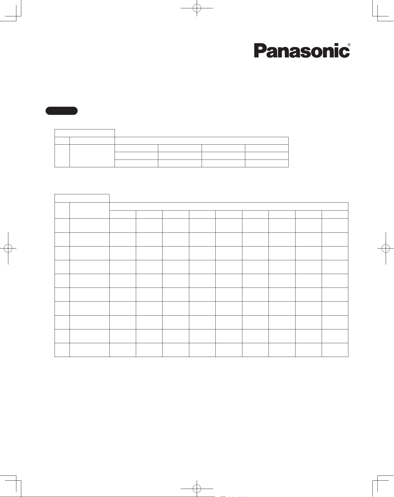
Model No.
Outdoor Units
Type Outdoor Unit Type Nominal Capacity
72 96 120 144
ME2 2WAY VRF System
U-72ME2U9 U-96ME2U9 U-120ME2U9 U-144ME2U9
U-72ME2U94 U-96ME2U94 U-120ME2U94 U-144ME2U94
• To be connecting Indoor Unit
Indoor Units
Type Indoor Unit Type
4-Way Cassette
U2
36" × 36"
4-Way Cassette
Y2
24" × 24"
D1 1-Way Cassette
Concealed Duct
F2
- Medium Static
Concealed Duct
M2
- Low Static
Concealed Duct
E1
- High Static
7 9 12 15 18 24 36 48 54
S-07MU2U6 S-09MU2U6 S-12MU2U6 S-24MU2U6 S-36MU2U6
S-07MY2U6 S-09MY2U6 S-12MY2U6 S-18MY2U6
S-07MD1U6 S-09MD1U6 S-12MD1U6
S-07MF2U6 S-09MF2U6 S-12MF2U6 S-15MF2U6 S-18MF2U6 S-24MF2U6 S-36MF2U6 S-48MF2U6 S-54MF2U6
S-07MM2U6 S-09MM2U6 S-12MM2U6 S-15MM2U6 S-18MM2U6
Nominal Capacity
S-36ME1U6 S-48ME1U6
T2 Ceiling
K2 Wall Mounted
P1 Floor Standing
Concealed Floor
R1
Standing
S-07MK2U6 S-09MK2U6 S-12MK2U6 S-18MK2U6 S-24MK2U6
S-07MP1U6 S-09MP1U6 S-12MP1U6 S-15MP1U6 S-18MP1U6 S-24MP1U6
S-07MR1U6 S-09MR1U6 S-12MR1U6 S-15MR1U6 S-18MR1U6 S-24MR1U6
S-12MT2U6 S-18MT2U6 S-24MT2U6
Read through the Installation Instructions before you proceed with the installation.
In particular, you will need to read under the “IMPORTANT!” section at the top of the page.
CV6231977845
85464369760022
ACXF60-18511
00_302411_EN.indd 1 2018/7/4 13:27:15
Page 2
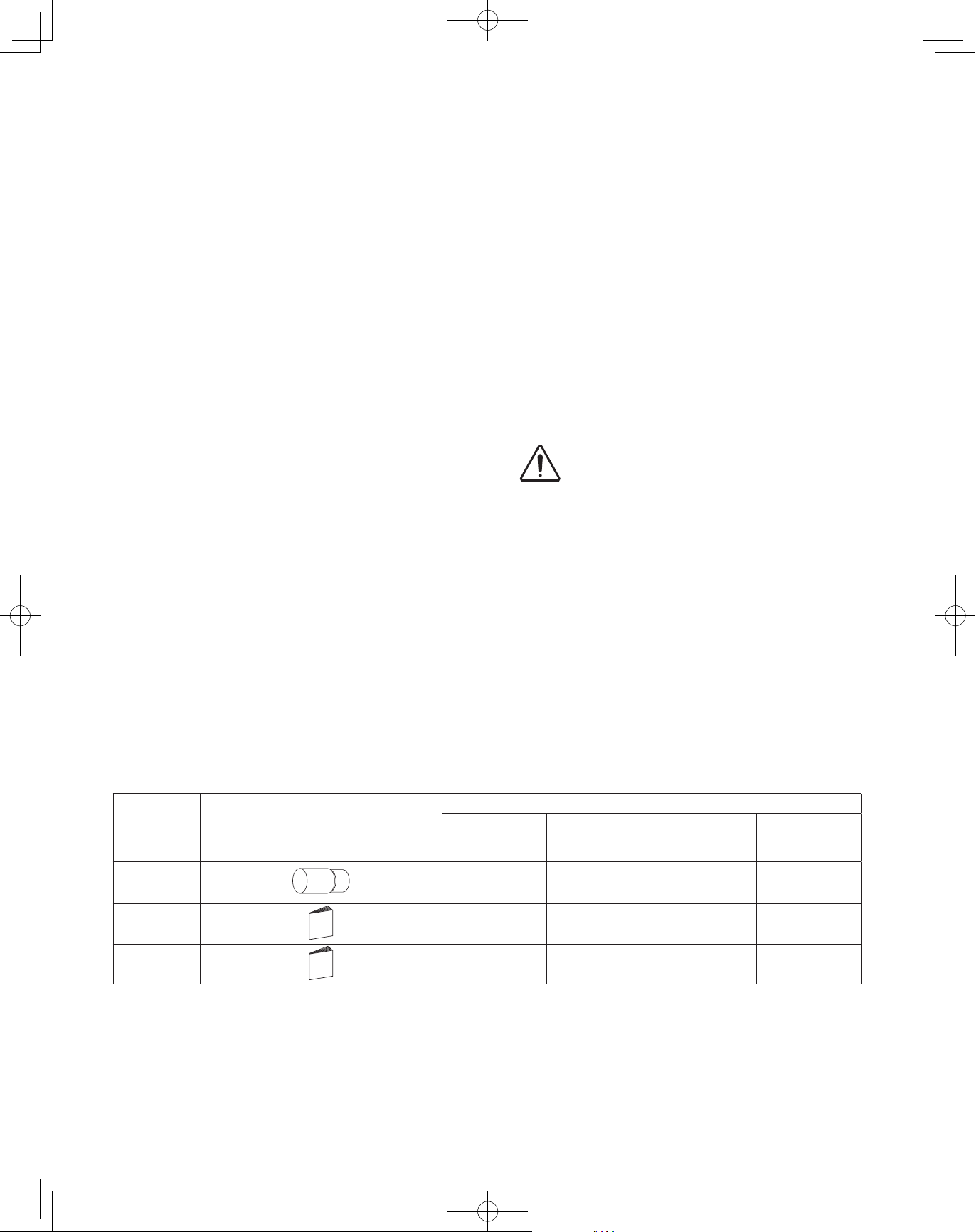
IMPORTANT!
WARNING
WARNING
WARNING
WARNING
WARNING
Please Read Before Starting
This air conditioning system meets strict safety and
operating standards. As the installer or service person, it is
an important part of your job to install or service the
system so it operates safely and efficiently.
For safe installation and trouble-free operation, you
must:
● Carefully read this instruction booklet before beginning.
● Follow each installation or repair step exactly as shown.
● This air conditioner shall be installed in accordance with
National Wiring Regulations.
● Pay close attention to all warning and caution notices
given in this manual.
This symbol refers to a hazard or
WARNING
CAUTION
If Necessary, Get Help
These instructions are all you need for most installation
sites and maintenance conditions. If you require help for a
special problem, contact our sales/service outlet or your
certified dealer for additional instructions.
In Case of Improper Installation
The manufacturer shall in no way be responsible for
improper installation or maintenance service, including
failure to follow the instructions in this document.
SPECIAL PRECAUTIONS
• Do not supply power to the unit until all wiring and tubing
are completed or reconnected and checked.
• Highly dangerous electrical voltages are used in this system.
Carefully refer to the wiring diagram and these instructions
when wiring. Improper connections and inadequate
grounding can cause accidental injury or death.
• Ground the unit following local electrical codes.
• Connect all wiring tightly. Loose wiring may cause over-
heating at connection points and a possible re hazard.
• To prevent possible hazards from insulation failure,
the unit must be grounded.
• This equipment is strongly recommended to be installed
with Earth Leakage Circuit Breaker (ELCB) or Residual
Current Device (RCD). Otherwise, it may cause electrical
shock and re in case of equipment breakdown or
insulation breakdown.
WARNING
ELECTRICAL SHOCK CAN CAUSE
SEVERE PERSONAL INJURY OR DEATH.
ONLY A QUALIFIED, EXPERIENCED
ELECTRICIAN SHOULD ATTEMPT TO
WIRE THIS SYSTEM.
unsafe practice which can result
in severe personal injury or death.
This symbol refers to a hazard or
unsafe practice which can result
in personal injury or product or
property damage.
When Wiring
When Transporting
Be careful when picking up and moving the indoor and
outdoor units. Get a partner to help, and bend your knees
when lifting to reduce strain on your back. Sharp edges or
thin aluminum fins on the air conditioner can cut your
fingers.
When Installing…
Select an installation location which is rigid and strong
enough to support or hold the unit, and select a location for
easy maintenance.
…In a Room
Properly insulate any tubing run inside a room to prevent
“sweating” that can cause dripping and water damage to
walls and floors.
Keep the fire alarm and the air
CAUTION
…In Moist or Uneven Locations
Use a raised concrete pad or concrete blocks to provide a
solid, level foundation for the outdoor unit. This prevents
water damage and abnormal vibration.
…In an Area with High Winds
Securely anchor the outdoor unit down with bolts and a
metal frame. Provide a suitable air bafe.
…In a Snowy Area (for Heat Pump-type Systems)
Install the outdoor unit on a raised platform that is higher
than drifting snow. Provide snow vents.
outlet at least 5 ft. (1.5 m) away
from the unit.
When Connecting Refrigerant Tubing
• Pay particular attention to refrigerant leakages.
• Ventilate the room immediately, in the event that is
refrigerant gas leaks during the installation. Be careful not
to allow contact of the refrigerant gas with a flame as this
will cause the generation of toxic gas.
• Keep all tubing runs as short as possible.
• Apply refrigerant lubricant to the matching surfaces of the
are and union tubes before connecting them, then tighten
the nut with a torque wrench for a leak-free connection.
• Check carefully for leaks before starting the test run.
WARNING
• When performing piping work, do not mix air
except for specified refrigerant (R410A) in
refrigeration cycle. It causes capacity down, and
risk of explosion and injury due to high tension
inside the refrigerant cycle.
• If the refrigerant comes in contact with a ame,
it produces a toxic gas.
• Do not add or replace refrigerant other than
specied type. It may cause product damage,
burst and injury, etc.
2
00_302411_EN.indd 2 2018/7/4 13:27:15
Page 3
• Do not leak refrigerant while piping work for an
WARNING
WARNING
WARNING
installation or re-installation, and while repairing
refrigeration parts.
Handle liquid refrigerant carefully as it may cause
frostbite.
When Servicing
• Turn the power OFF at the main power box (mains)
before opening the unit to check or repair electrical
parts and wiring.
• Keep your fingers and clothing away from any moving
parts.
• Clean up the site after you nish, remembering to
check that no metal scraps or bits of wiring have been
left inside the unit .
WARNING
• This product must not be modied or
disassembled under any circumstances.
Modied or disassembled unit may cause re,
electric shock or injury.
• Do not clean inside the indoor and outdoor
units by users. Engage authorized dealer or
specialist for cleaning.
• In case of malfunction of this appliance, do
not repair by yourself. Contact to the sales
dealer or service dealer for a repair.
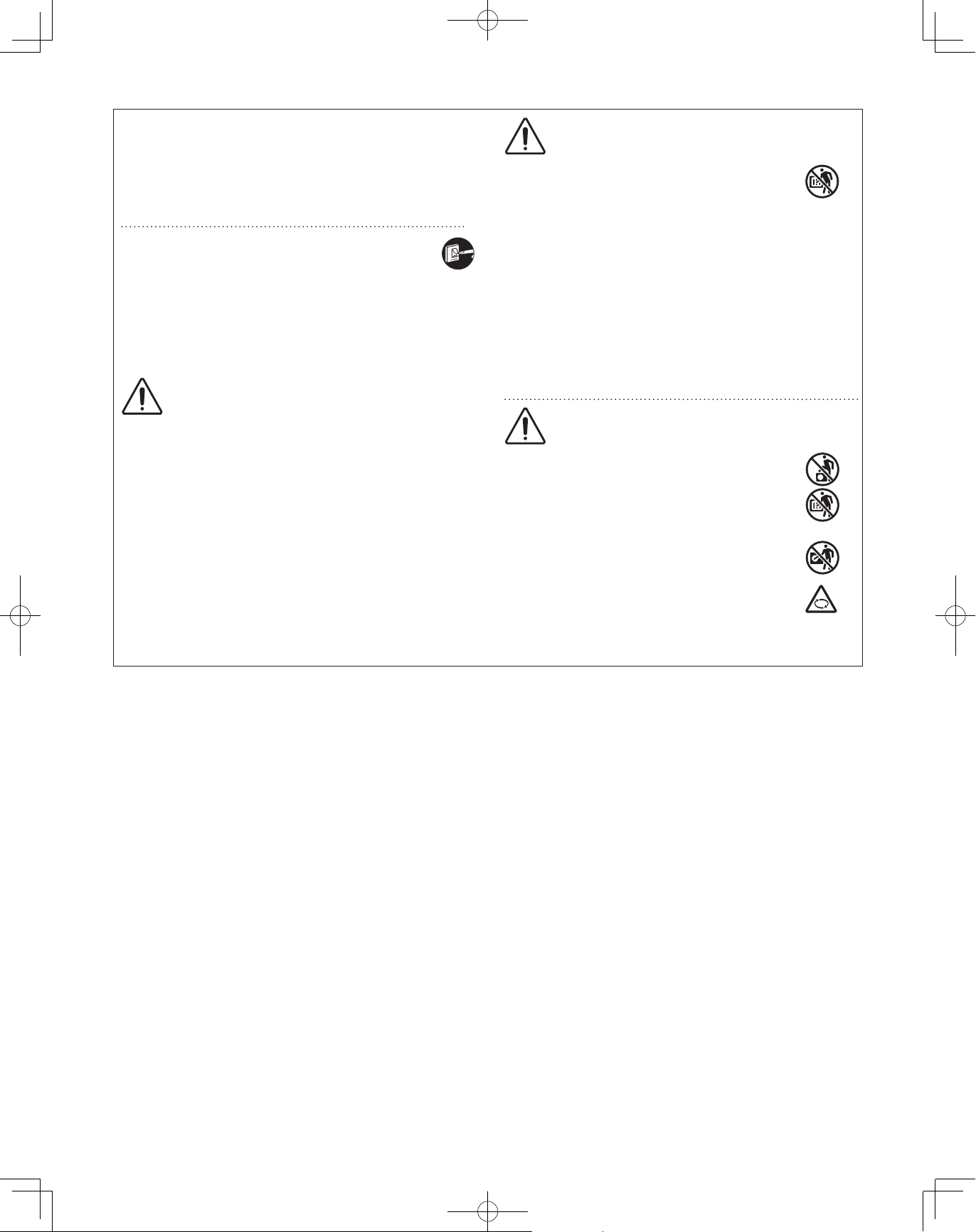
CAUTION
• Do not touch the air inlet or the sharp
aluminum fins of the outdoor unit. You
may get injured.
• Ventilate any enclosed areas when installing or
testing the refrigeration system. Leaked
refrigerant gas, on contact with re or heat, can
produce dangerously toxic gas.
• Conrm after installation that no refrigerant gas
is leaking. If the gas comes in contact with a
burning stove, gas water heater, electric room
heater or other heat source, it can cause the
generation of toxic gas.
Others
CAUTION
• Do not sit or step on the unit, you may
fall down accidentally.
• Do not touch the air inlet or the sharp
aluminum fins of the outdoor unit.
You may get injured.
• Do not stick any object into the FAN
CASE.
You may be injured and the unit may
be damaged.
Check of Density Limit
The room in which the air conditioner is to be
installed requires a design that in the event of
refrigerant gas leaking out, its density will not exceed
a set limit.
The refrigerant (R410A), which is used in the air
conditioner, is safe, without the toxicity or combustibility of
ammonia, and is not restricted by laws imposed to protect
the ozone layer. However, since it contains more than air,
it poses the risk of suffocation if its density should rise
excessively. Suffocation from leakage of refrigerant is
almost non-existent. With the recent increase in the
number of high density buildings, however, the installation
of multi air conditioner systems is on the increase
because of the need for effective use of oor space,
individual control, energy conservation by curtailing heat
and carrying power, etc.
Most importantly, the multi air conditioner system is able
to replenish a large amount of refrigerant compared to
conventional individual air conditioners.
If a single unit of the multi air conditioner system is to be
installed in a small room, select a suitable model and
installation procedure so that if the refrigerant
accidentally leaks out, its density does not reach the limit
(and in the event of an emergency, measures can be
made before injury can occur).
ASHRAE and the International Mechanical Code of the
ICC as well as CSA provide guidance and dene
safeguards related to the use of refrigerants, all of which
dene a Refrigerant Concentration Level (RCL) of 400 oz
3
(11.3 kg) per 1,000 ft
(28.3 m3) for R410A refrigerant.
For additional guidance and precautions related to
refrigerant safety, please refer to the following documents:
International Mechanical Code 2012 (IMC-2012)
(or more recently revised)
ASHRAE 15
ASHRAE 34
3
00_302411_EN.indd 3 2018/7/4 13:27:15
Page 4
Precautions for Installation Using New Refrigerant
CAUTION
1. Care regarding tubing
1-1. Process tubing
●
Material: Use seamless phosphorous deoxidized copper tube for refrigeration. Wall thickness shall comply with the
applicable legislation. The minimal wall thickness must be in accordance with the table below.
●
Tubing size: Be sure to use the sizes indicated in the table below.
●
Use a tube cutter when cutting the tubing, and be sure to remove any flash. This also applies to distribution joints
(optional).
●
When bending tubing, use a bending radius that is 4 times the outer diameter of the tubing or larger.
Outer diameter Wall thickness Outer diameter Wall thickness
CAUTION
Material: O Material: O
1/4" (6.35) 0.025 (0.635) 7/8" (22.22) 0.045 (1.143)
3/8" (9.52) 0.030 (0.762) 1-1/8" (28.58) 0.050 (1.27)
1/2" (12.7) 0.035 (0.889) 1-3/8" (34.92) 0.055 (1.397)
5/8" (15.88) 0.040 (1.016) 1-5/8" (41.28) 0.060 (1.524)
3/4" (19.05) 0.042 (1.0668) Unit: in. (mm)
1-2. Prevent impurities including water, dust and oxide from entering the tubing. Impurities can cause R410A
refrigerant deterioration and compressor defects. Due to the features of the refrigerant and refrigerating machine
oil, the prevention of water and other impurities becomes more important than ever.
Use sufficient care in handling the tubing. Seal the tubing ends with caps or tape to
prevent dirt, moisture, or other foreign substances from entering.
These substances can result in system malfunction.
2. Be sure to recharge the refrigerant only in liquid form.
2-1. Since R410A is a non-azeotrope, recharging the refrigerant in gas form can lower performance and cause defects
in the unit.
2-2. Since refrigerant composition changes and performance decreases when gas leaks, collect the remaining
refrigerant and recharge the required total amount of new refrigerant after fixing the leak.
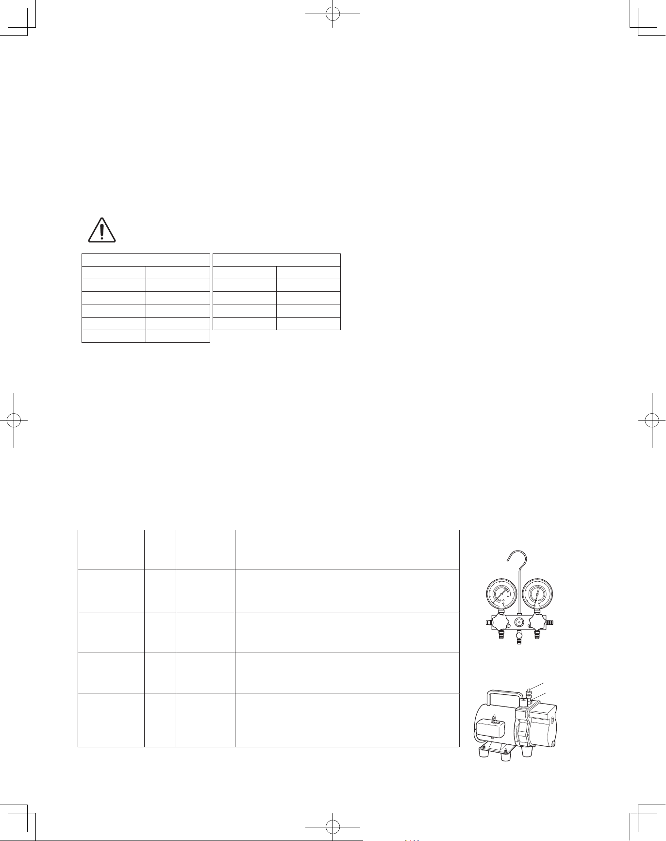
3. Different tools required
3-1. Tool specifications have been changed due to the characteristics of R410A.
Some tools for R22- and R407C-type refrigerant systems cannot be used.
R407C tools
Item
Manifold gauge Yes No
Charge hose Yes No To resist higher pressure, material must be changed.
Vacuum pump Yes Yes
Leak detector Yes No
Flaring oil Yes No
* Using tools for R22 and R407C and new tools for R410A together can cause defects.
New
tools?
compatible
with R410A?
Remarks
Types of refrigerant, refrigerating machine oil, and
pressure gauge are different.
Use a conventional vacuum pump if it is equipped with
a check valve. If it has no check valve, purchase and
attach a vacuum pump adapter.
Leak detectors for CFC and HCFC that react to chlorine
do not function because R410A contains no chlorine.
Leak detector for HFC134a can be used for R410A.
For systems that use R22, apply mineral oil (Suniso
oil) to the flare nuts on the tubing to prevent refrigerant
leakage. For machines that use R407C or R410A, apply
synthetic oil (ether oil) to the flare nuts.
Manifold gauge
Vacuum pump
Outlet
Inlet
4
00_302411_EN.indd 4 2018/7/4 13:27:15
Page 5
3-2. Use R410A exclusive cylinder only.
New refrigerant R410A cannot be used for
earlier models
1. Compressor specifications are different.
If recharging a R22 or R407C compressor with
R410A, durability will significantly decrease since
some of the materials used for compressor parts are
different.
Valve
Single-outlet valve
(with siphon tube)
Liquid refrigerant should be recharged
with the cylinder standing on end as
shown.
Liquid
2. Existing tubing cannot be used (especially R22).
Completely cleaning out residual refrigerating
machine oil is impossible, even by flushing.
3. Refrigerating machine oil differs (R22).
Since R22 refrigerating machine oil is mineral oil, it
does not dissolve in R410A. Therefore, refrigerating
machine oil discharged from the compressor can
cause compressor damage.
R22 refrigerating machine oil Mineral oil (Suniso oil)
R407C refrigerating machine oil Synthetic fluid (ether oil)
R410A refrigerating machine oil Synthetic fluid (ether oil)
5
00_302411_EN.indd 5 2018/7/4 13:27:15
Page 6
CONTENTS
Page Page
IMPORTANT! . . . . . . . . . . . . . . . . . . . . . . . . . . . . . 2
Please Read Before Starting
Check of Density Limit
Precautions for Installation Using New Refrigerant
New refrigerant R410A cannot be used for earlier models
1. GENERAL . . . . . . . . . . . . . . . . . . . . . . . . . . . . . 7
1-1. Tools Required for Installation (not supplied)
1-2. Accessories Supplied
1-3. Type of Copper Tube and Insulation Material
1-4. Additional Materials Required for Installation
1-5. Tubing Length
1-6. Tubing Size
1-7. Straight Equivalent Length of Joints
1-8. Additional Refrigerant Charge
1-9. System Limitations
1-10. Check of Limit Density
1-11. Installing Distribution Joint
1-12. Optional Distribution Joint Kits
1-13. Example of Tubing Size Selection and
Refrigerant Charge Amount
2. SELECTING THE INSTALLATION SITE . . . . . 17
5. HOW TO PROCESS TUBING . . . . . . . . . . . . . 34
5-1. Connecting the Refrigerant Tubing
5-2. Connecting Tubing Between Indoor and
Outdoor Units
5-3. Insulating the Refrigerant Tubing
5-4. Taping the Tubes
5-5. Finishing the Installation
6. AIR PURGING . . . . . . . . . . . . . . . . . . . . . . . . . 37
Air Purging with a Vacuum Pump (for Test Run)
n
Preparation
7. TEST RUN . . . . . . . . . . . . . . . . . . . . . . . . . . . . 40
7-1. Preparing for Test Run
7-2. Test Run Procedure
7-3. Main Outdoor Unit PCB Setting
7-4. Function Switches on P.C. Board
7-5. Auto Address Setting
7-6. Setting Test Run Remote Controller
7-7. Caution for Pump Down
7-8. Self-Diagnosis Function Table and Contents of
Alarm Display
2-1. Outdoor Unit
2-2. Shield for Horizontal Exhaust Discharge
2-3. Installing the Outdoor Unit in Heavy Snow
Areas
2-4. Precautions When Installing in Heavy Snow
Areas
2-5. Dimensions of Wind Ducting
2-6. Dimensions of Snow Ducting
3. HOW TO INSTALL THE OUTDOOR UNIT . . . . 23
3-1. Transporting
3-2. Installing the Outdoor Unit
3-3. Routing the Tubing
3-4. Prepare the Tubing
3-5. Connect the Tubing
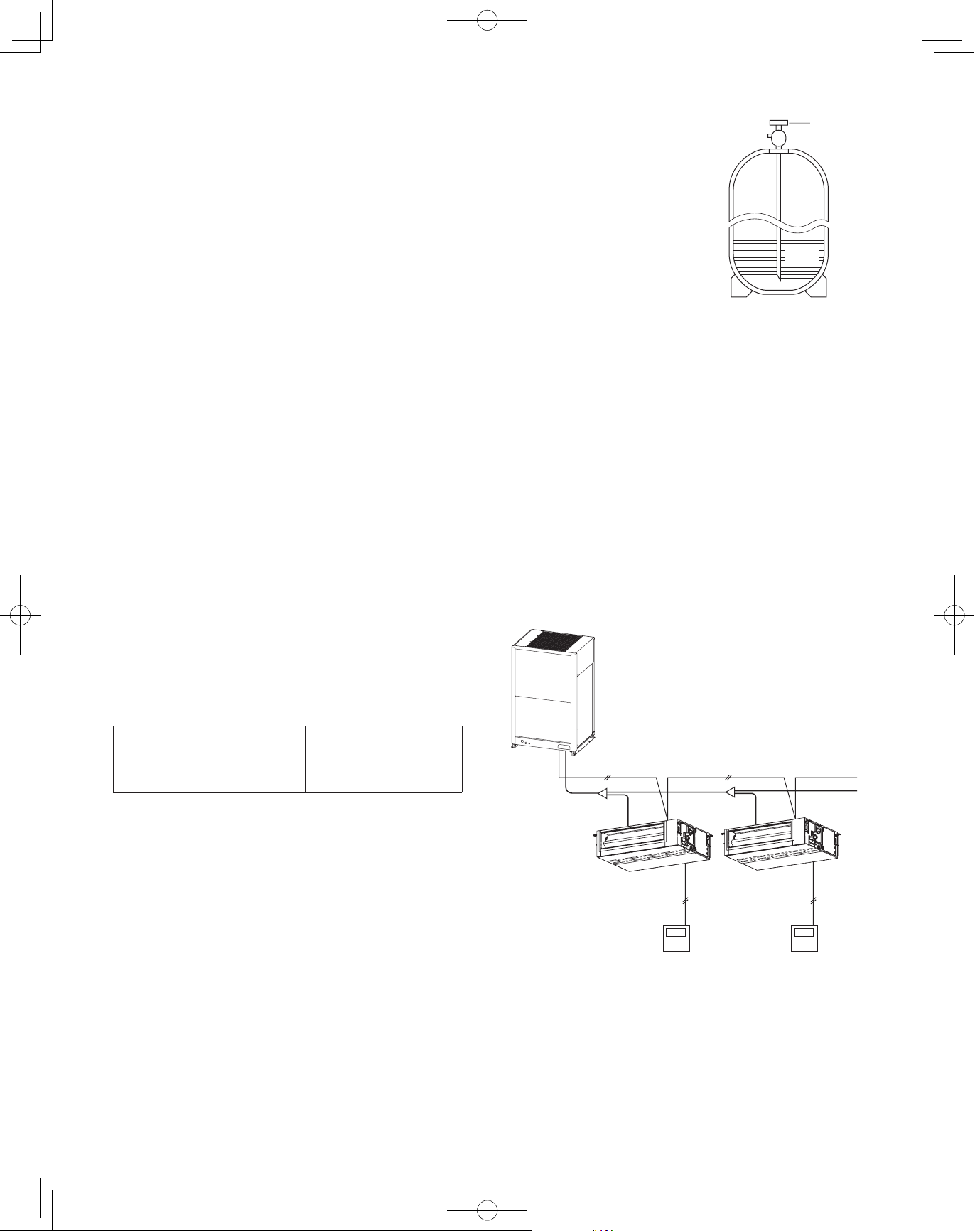
4. ELECTRICAL WIRING . . . . . . . . . . . . . . . . . . 28
4-1. General Precautions on Wiring
4-2. Recommended Wire Length and Wire
Diameter for Power Supply System
4-3. Wiring System Diagram
6
00_302411_EN.indd 6 2018/7/4 13:27:15
Page 7
CAUTION
1. GENERAL
This booklet briefly outlines where and how to install the air conditioning system. Please read over the entire set of instructions for
the outdoor unit and make sure all accessory parts listed are with the system before beginning.
1-1. Tools Required for Installation (not supplied)
1. Flathead screwdriver
2. Phillips head screwdriver
3. Knife or wire stripper
4. Tape measure
5. Level gauge
6. Sabre saw or keyhole saw
7. Hacksaw
8. Core bits
9. Hammer
10. Drill
11. Tube cutter
12. Tube flaring tool
13. Torque wrench
14. Adjustable wrench
15. Reamer (for deburring)
1-2. Accessories Supplied
See Table 1.
1-3. Type of Copper Tube and Insulation Material
If you wish to purchase these materials separately from a local
source, you will need:
1. Deoxidized annealed copper tube for refrigerant tubing.
2. Foamed polyethylene insulation for copper tubes as
required to precise length of tubing. Wall thickness of the
insulation should be not less than 5/16" (7.94mm).
3. Use insulated copper wire for field wiring. Wire size varies
with the total length of wiring.
“
See the section
4. ELECTRICAL WIRING” for details.
Check local electrical codes and
CAUTION
regulations before obtaining
wire. Also, check any specified
instructions or limitations.
1-4. Additional Materials Required for Installation
1. Refrigeration (armored) tape
2. Insulated staples or clamps for connecting wire
(See your local codes.)
3. Putty
4. Refrigeration tubing lubricant
5. Clamps or saddles to secure refrigerant tubing
6. Scale for weighing
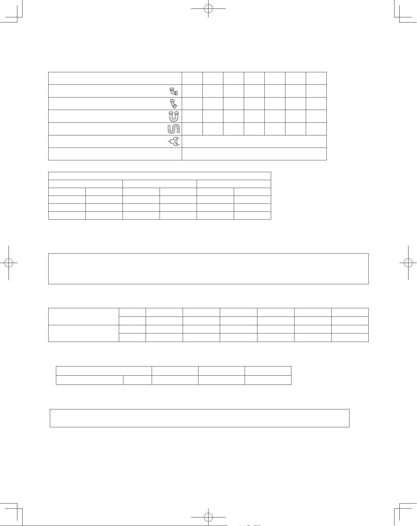
Table 1 Outdoor Unit
Part name Figure
Connection
tubing
Operating
Instructions
Installation
Instructions
Outer
diameter
ø1-1/8"(ø28.58)
Inner
diameter
ø1"(ø25.4)
paper
paper
Q’ty
U-72ME2U9
U-72ME2U94
(6 ton)
U-96ME2U9
U-96ME2U94
(8 ton)
U-120ME2U9
U-120ME2U94
(10 ton)
0 0 1 1
1 1 1 1
1 1 1 1
7
U-144ME2U9
U-144ME2U94
(12 ton)
00_302411_EN.indd 7 2018/7/4 13:27:16
Page 8
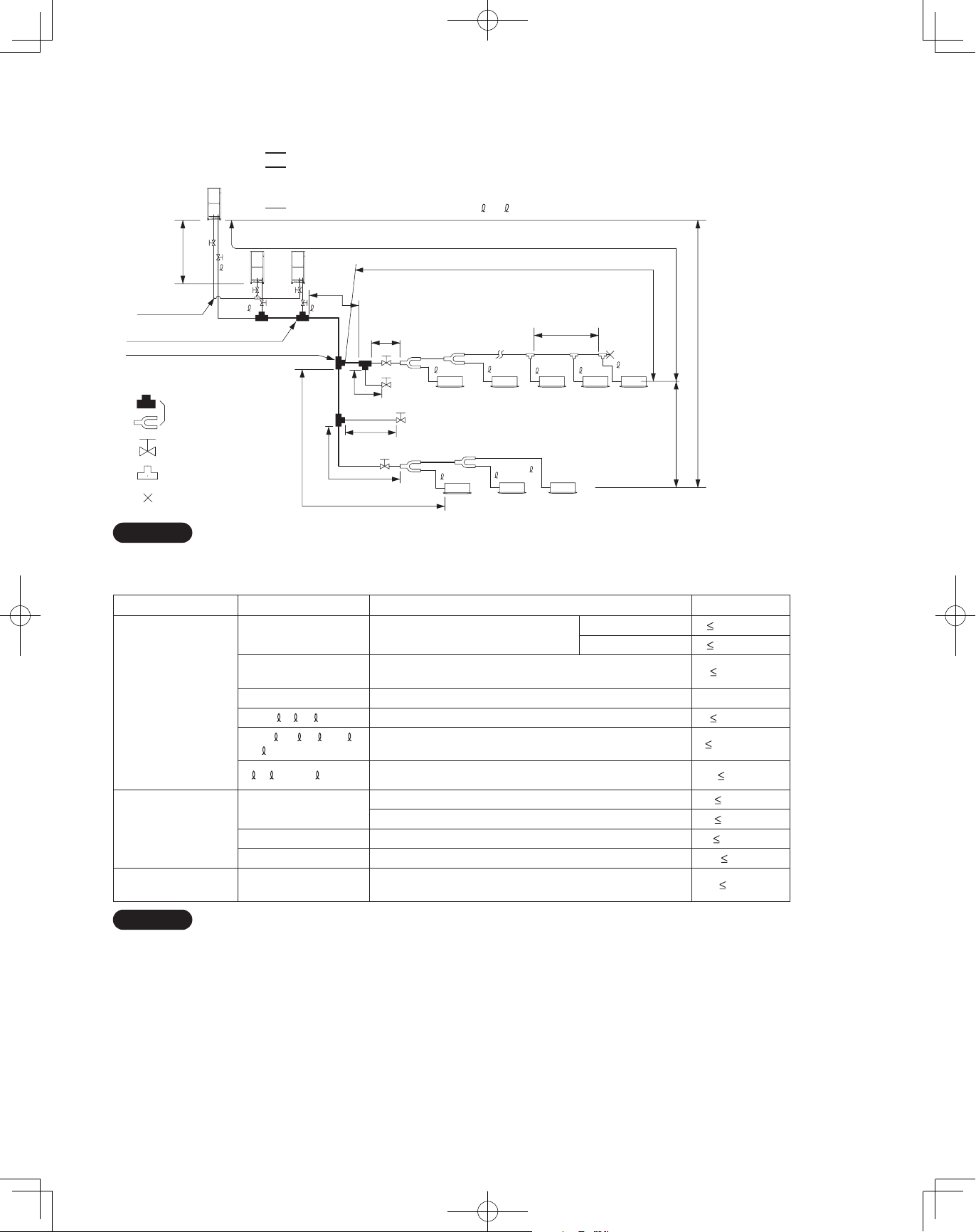
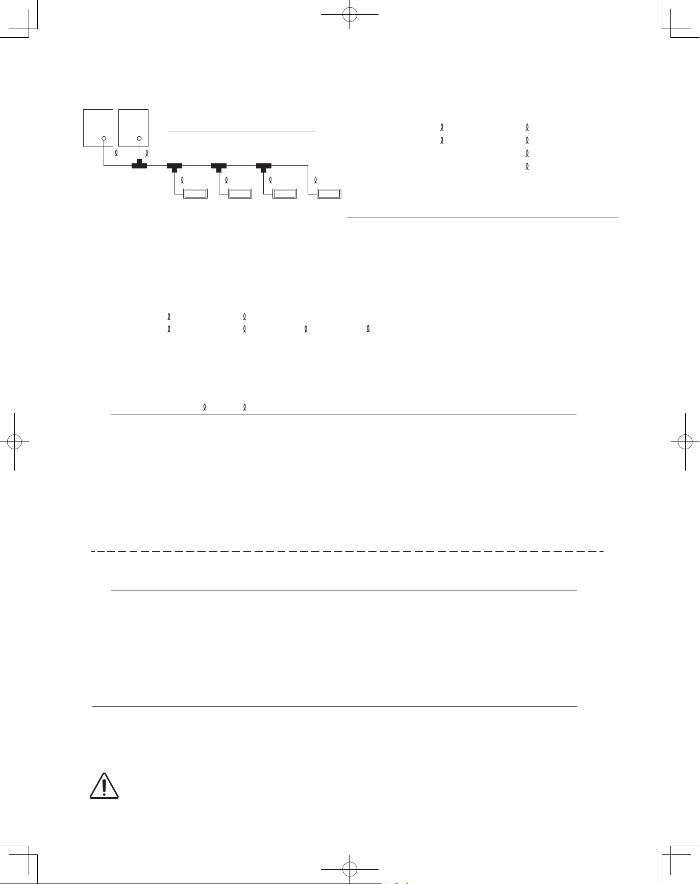
1-5. Tubing Length
Select the installation location so that the length and size of refrigerant tubing are within the allowable range show in the figure below.
1.
Main tubing length (maximum tubing size) LM = LA + LB …
2. Main distribution tubes LC – LH are selected according to the capacity after the distribution joint.
3. The outdoor connection main tubing (LO portion) is determined by the total capacity of the outdoor units that are
connected to the tube ends.
4.
Sizes of indoor unit connection tubing
1 – 64 are determined by the connection tubing sizes on the indoor units.
H3
C
Balance tubing
(ø1/4" (6.35mm))
No.1 distribution joint for outdoor unit
No.1 distribution joint (for indoor unit)
Explanation of symbols
Distribution joint
(CZ: optional parts)
Ball valve (field supply)
T-joint (field supply)
Solidly welded shut
(pinch weld)
LO
LM
AB
LA
LB
LF
Max.1.3 ft (40cm)
Max.1.3 ft (40cm)
LG
L4
LC
For
extension
LD
For
extension
LH
4
1
L1
L2
3L
5
62
3
2
64
63
H2
R410A optional distribution joint
CZ-P680PJ1U (for outdoor unit)
CZ-P1350PJ1U (for outdoor unit)
CZ-P160BK1U (for indoor unit)
CZ-P680BK1U (for indoor unit)
CZ-P1350BK1U (for indoor unit)
H1
NOTE
* Be sure to use special R410A distribution joints (CZ: optional parts) for outdoor unit connections and tubing branches.
Table 1-2 Ranges that Apply to Refrigerant Tubing Lengths and to Differences in Installation Heights
Item Mark Contents Length
Actual length
Equivalent length
Allowable tubing
length
Allowable elevation
difference
Allowable length of
joint tubing
L1 Max. tubing length
L (L2 – L4)
Difference between max. length and min.
length from the No.1 distribution joint
LM Max. length of main tubing (at maximum size)
1, 2~ 64 Max. length of each distribution tube
L1 + 1 + 2~ 63 + A
+ B + LF + LG + LH
A, B + LO, C + LO
H1
Total max. tubing length including length of each distribution
tube (only liquid tubing)
Maximum tubing length from outdoor’s 1st distribution
joint to each outdoor unit
When outdoor unit is installed higher than indoor unit
When outdoor unit is installed lower than indoor unit
H2 Max. difference between indoor units
H3 Max. difference between outdoor units
L3
T-joint tubing (field-supply); Max. tubing length between the
first T-joint and solidly welded-shut end point
unit: ft. (m)
656 (200)*
689 (210)*
164 (50)*
-
164 (50)*
3280 (1000)
33 (10)
164 (50)
131 (40)
49 (15)*
13 (4)
6.6 (2)
4
3
*
6
5
2
2
L = Length
H = Height
NOTE
1: The outdoor connection main tubing (LO portion) is determined by the total capacity of the outdoor units that are connected to
the tube ends.
2: If the longest tubing length (L1) exceeds 295 ft. (90m) (equivalent length), increase the sizes of the main tubes (LM) by 1 rank for
gas tubes and liquid tubes. (Use a field supply reducer.) (Select the tube size from the table of main tube sizes (Table 1-3) on the
following page (LA table), and from the table of refrigerant tubing sizes (Table 1-9) on the second following page.)
3: If the longest main tubing length (LM) exceeds 164 ft. (50m), increase the main tube size at the portion before 164 ft. (50m) by 1
rank for the gas tubes. (Use a field supply reducer.)
(For the portion that exceeds 164 ft. (50m), set based on the main tube sizes (LA) listed in the table on the following page.)
4: If the tubing length marked "L" (L2 - L4) exceeds 131 ft. (40m), increase the liquid tube and gas tube by 1 rank.
5: If the total distribution tubing length exceeds 1,640ft. (500m), maximum allowable elevation difference (H2) between the indoor
units is calculated by the following formula. Make sure the indoor unit’s actual elevation difference should fall within the figure
calculated as follows.
Unit of account (feet): 49 x (2 - total tubing length(ft.) ÷ 1,640) or Unit of account (meter): 15 x (2 - total tubing length(m) ÷ 500)
6: If any of the tubing length exceeds 98ft. (30m), increase the size of the liquid and gas tubes by 1 rank.
8
00_302411_EN.indd 8 2018/7/4 13:27:16
Page 9

1-6. Tubing Size
Table 1-3 Main Tubing Size (LA)
Between No.1 distribution joint for outdoor unit and No.1 distribution joint (for indoor unit)
BTU/h
(kW)
Total system
tonnage
Gas tubing
Liquid tubing
72,000
(21.1)
ø3/4"
(ø19.05)
96,000
(28.1)
6 8 10 12 14 16 18 20 22 24 26 28 30
ø7/8"
(ø22.22)
ø3/8"
(ø9.52)
120,000
(35.2)
(ø12.7)
ø1/2"
144,000
(42.2)
168,000
(49.2)
ø1-1/8"
(ø28.58)
192,000
(56.3)
ø5/8"
(ø15.88)
216,000
(63.3)
240,000
(70.3)
264,000
(77.4)
288,000
(84.4)
ø1-3/8"
(ø34.92)
(ø19.05)
312,000
(91.4)
ø3/4"
*1: If future extension is planned, select the tubing diameter based on the total tonnage after extension.
However, extension is not possible if the resulting tubing size is three ranks higher.
*2: The balance tube (outdoor unit tube) diameter is ø1/4" (6.35mm).
*3: Type 1 tubing should be used for the refrigerant tubes.
Size of tubing (LO) between outdoor units
n
Select the size of tubing between outdoor units based on the main tubing size (LA) as given in the table above.
Table 1-4 Main Tubing Size After Distribution (LB, LC...)
Total capacity
after distribution
Tubing size
Below BTU/h (kW)
Over BTU/h (kW) –
Gas tubing
Liquid tubing
24,200
(7.09)
ø1/2"
(ø12.7)
ø3/8"
(ø9.52)
54,600
(16.0)
24,200
(7.09)
ø5/8"
(ø15.88)
ø3/8"
(ø9.52)
76,800
(22.5)
54,600
(16.0)
ø3/4"
(ø19.05)
ø3/8"
(ø9.52)
102,400
(30.0)
76,800
(22.5)
ø7/8"
(ø22.22)
ø3/8"
(ø9.52)
143,300
(42.0)
102,400
(30.0)
ø1-1/8"
(ø28.58)
ø1/2"
(ø12.7)
178,800
(52.4)
143,300
(42.0)
ø1-1/8"
(ø28.58)
ø1/2"
(ø12.7)
238,900
(70.0)
178,800
(52.4)
ø1-1/8"
(ø28.58)
ø5/8"
(ø15.88)
340,000
(99.6)
238,900
(70.0)
ø1-3/8"
(ø34.92)
ø3/4"
(ø19.05)
Note: In case the total capacity of connected indoor units exceeds the total capacity of the outdoor units, select the main tubing size
for the total capacity of the outdoor units.
Unit: in. (mm)
336,000
(98.4)
Unit: in. (mm)
–
340,000
(99.6)
ø1-5/8"
(ø41.28)
ø3/4"
(ø19.05)
360,000
(105.5)
ø1-5/8"
(ø41.28)
A
Table 1-5 Outdoor Unit Tubing Connection Size (
BTU/h
(kW)
Gas tubing
Liquid tubing
Balance tubing
72,000
(21.1)
ø3/4"
(ø19.05)
ø3/8" (ø9.52) ø3/8" (ø9.52) ø1/2" (ø12.7)
96,000
(28.1)
ø7/8"
(ø22.22)
Brazing connection
Flare connection
ø1/4" (ø6.35)
Flare connection
120,000
(35.2)
–
ø1-1/8"
(ø28.58)
C
)
Unit: in. (mm)
144,000
(42.2)
ex.) type72
Balance
tube
Liquid tube
Table 1-6 Refrigerant Charge Amount at Shipment (for outdoor unit)
BTU/h (kW) 72,000 (21.1) 96,000 (28.1) 120,000 (35.2) 144,000 (42.2)
Initial amount
Table 1-7 Indoor Unit Tubing Connection Size
oz (g) 321 (9,100) 363 (10,300) 300 (8,500) 416 (11,800)
Unit: in. (mm)
Indoor unit type 7 9 12 15 18 24 36 48 54
Gas tubing ø1/2" (ø12.7) ø5/8" (ø15.88)
Liquid tubing ø1/4" (ø6.35) ø3/8" (ø9.52)
Gas tube
9
00_302411_EN.indd 9 2018/7/4 13:27:17
Page 10
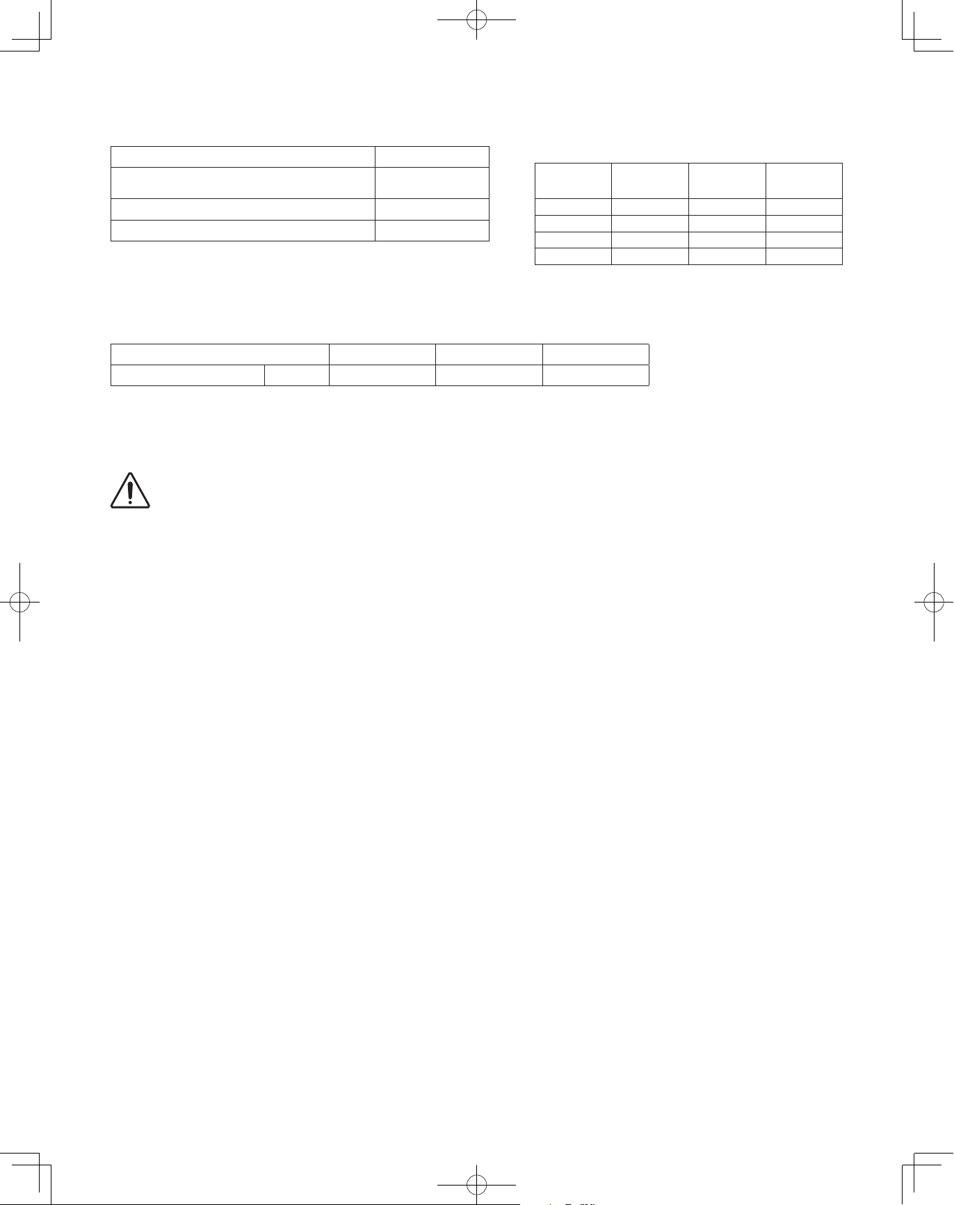
1-7. Straight Equivalent Length of Joints
Design the tubing system by referring to the following table for the straight equivalent length of joints.
Table 1-8 Straight Equivalent Length of Joints
Gas tubing size (in. (mm))
90° elbow
45° elbow
U-shape tube bent (R2-3/8" – 4" (60 – 100mm))
Trap bend
Y-branch distribution joint
Ball valve for service Equivalent length conversion not needed.
1/2"
(12.7)
(0.30)
0.8
(0.23)
(0.90)
7.5
(2.30)
Table 1-9 Refrigerant tubing (Existing tubing can be used.)
Tubing size (in. (mm))
Material: O Material: O Material: O
Outer diameter Wall thickness Outer diameter Wall thickness Outer diameter Wall thickness
1/4" (6.35) 0.025 (0.635) 5/8" (15.88) 0.040 (1.016) 1-1/8" (28.58) 0.050 (1.27)
3/8" (9.52) 0.030 (0.762) 3/4" (19.05) 0.042 (1.0668) 1-3/8" (34.92) 0.055 (1.397)
1/2" (12.7) 0.035 (0.889) 7/8" (22.22) 0.045 (1.143) 1-5/8" (41.28) 0.060 (1.524)
1
3
5/8"
(15.88)
1.1
(0.35)
0.9
(0.26)1(0.32)
3.4
(1.05)
9.2
(2.80)
Equivalent length conversion not needed.
3/4"
(19.05)
1.4
(0.42)
4.1
(1.26)
10.5
(3.20)
7/8"
(22.22)
1.6
(0.48)
1.2
(0.36)
4.7
(1.44)
12.5
(3.80)
1-1/8"
(28.58)
1.9
(0.57)
1.4
(0.43)
5.6
(1.71)
15.4
(4.70)
* When bending the tubes, use a
bending radius that is at least 4 times
the outer diameter of the tubes.
In addition, take sufficient care to
avoid crushing or damaging the tubes
when bending them.
1-3/8"
(34.92)
2.5
(0.76)
1.8
(0.55)
7.4
(2.26)
19.2
(5.85)
Unit: ft. (m)
1-5/8"
(41.28)
2.8
(0.85)
2.0
(0.61)
8.4
(2.56)
22.3
(6.80)
1-8. Additional Refrigerant Charge
Additional refrigerant charge amount is calculated from the liquid tubing total length, combination number of outdoor unit and
refrigerant amount according to all indoor unit cooling capacity.
Required amount of additional refrigerant charge
= [(Necessary amount of additional refrigerant charge per ft. (m) of each size of liquid tube x its tube length) + (...) + (...)]
+ [Necessary amount of additional refrigerant charge per outdoor unit]
+ [Necessary amount of additional refrigerant charge for all indoor unit cooling capacity]
* Always charge accurately using a scale for weighing.
Table 1-10-1 Necessary Amount of Additional Refrigerant Charge Per ft. (or per meter), According to Liquid Tubing Size
Liquid tubing size
Additional amount
Table 1-10-2 Necessary Amount of Additional Refrigerant Charge Per Outdoor Unit
Further charge a certain amount listed below in addition to the amount of refrigerant charge.
Combination number of outdoor unit 1 2 3
Additional amount oz (g) 70.5 (2,000) 141.0 (4,000) 212 (6,000)
Necessary Amount of Additional Refrigerant Charge for All Indoor Unit Cooling Capacity
Charge a refrigerant amount calculated in the following formula according to the total amount of indoor unit cooling capacity.
inch ø1/4" ø3/8" ø1/2" ø5/8" ø3/4" ø7/8"
(mm) (ø6.35) (ø9.52) (ø12.7) (ø15.88) (ø19.05) (ø22.22)
oz/ft. 0.279 0.602 1.38 1.99 2.78 3.93
(g/m) (26) (56) (128) (185) (259) (366)
Additional refrigerant amount when cooling capacity is BTU/h = Cooling capacity (BTU/h) x 1.034 x 0.001 + 10.6 (oz)
or Additional refrigerant amount when cooling capacity is kW = Cooling capacity (kW) x 1000 x 0.1 + 300 (g)
10
00_302411_EN.indd 10 2018/7/4 13:27:17
Page 11
1-9. System Limitations
CAUTION
Table 1-11 System Limitations
Max. No. allowable connected outdoor units 3
Max. capacity allowable connected outdoor
units
360,000 BTU/h
(30 ton, 105.5 kW)
Max. connectable indoor units 64
Max. allowable indoor/outdoor capacity ratio 50 – 200 %
*2
*1
*3
*1: In the case of 18 ton (63.3kW) or smaller units, the number is
limited by the total capacity of the connected indoor units.
*2: Up to 3 units can be connected if the system has been extended.
*3: It is strongly recommended that you choose the unit so the load
can become between 50 and 130%.
Table 1-12 System Limitations of Total Refrigerant Amount
Combination number of outdoor unit 1 2 3
g
Upper limit oz (
) 1,763 (50,000) 2,821 (80,000) 3,703 (105,000)
Make sure the values calculated using the following formula should not exceed the maximum allowable values (Table 1-12).
Total refrigerant amount = Refrigerant charge amount at shipment (for outdoor unit)
+ Necessary amount of additional refrigerant charge per ft. (or per meter) according to liquid tubing size
+ Necessary amount of additional refrigerant charge per outdoor unit
+ Necessary amount of additional refrigerant charge for all indoor unit cooling capacity
Maximum number of connectable indoor units
when connected with minimum capacity
Total system
tonnage
Number of
indoor units
Total system
tonnage
Number of
indoor units
6 20 14 45
8 25 16 50
10 32 18 55
12 39 20~30 64
WARNING
Always check the gas density limit for the room in which the unit is installed.
1-10. Check of Limit Density
When installing an air conditioner in a room, it is necessary to ensure that even if the refrigerant gas accidentally leaks out, its
density does not exceed the limit level for that room.
11
00_302411_EN.indd 11 2018/7/4 13:27:17
Page 12
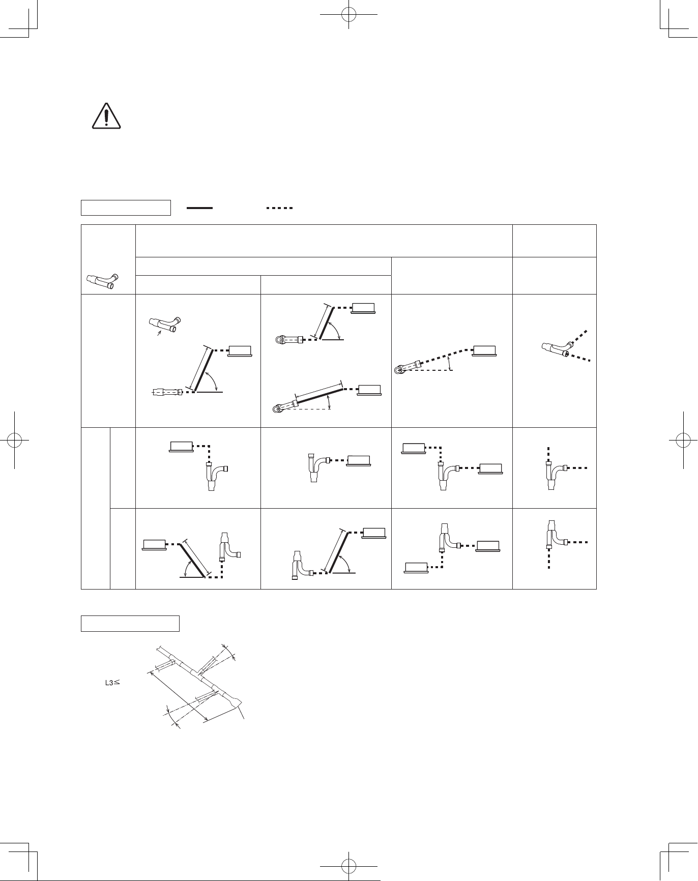
1-11. Installing Distribution Joint
CAUTION
15〜90°
CAUTION
Pay special attention to any location, such as a basement, etc., where leaking refrigerant can
accumulate, since refrigerant gas is heavier than air.
(1) Refer to “HOW TO ATTACH DISTRIBUTION JOINT” enclosed with the optional distribution joint kit (CZ-P680PJ1U,
CZ-P1350PJ1U, CZ-P160BK1U, CZ-P680BK1U, CZ-P1350BK1U).
● When connecting a branch tubing to the indoor unit directly, it is necessary for each branch tubing to install at a positive angle
with respect to horizontal in order to prevent accumulation of refrigerant oil in stopped units. (See the below chart.)
Branch tubing system Restricted
How to install
branch tubing
B
A
Horizontal
* In case of common use solenoid valve kit
When connecting to A When connecting to B
B
A
D
Straight tubing
length over
8 in. (200mm)
Arrow view D
When connecting branch tubing to indoor unit directly
Suction tube
15〜90°
Not restricted
Straight tubing
length over
8 in. (200mm)
Horizontal
Straight tubing length
over 8 in. (200mm)
or
15〜90°
15〜30°
(Branch tubing
angle)
Liquid tube / Discharge tube
0〜30°
(Branch tubing
angle)
When not connecting
branch tubing to indoor
unit directly
Suction tube /
Discharge tube /
Liquid tube
Horizontal
Upward
Vertical
Downward
Header branch system
Outdoor
Indoor
6.5 ft. (2m)
(From 1st branch to tip
of solidly welded part)
Horizontal line
Install at a positive angle
Vertical
Straight tubing
length over
8 in. (200mm)
15〜90°
(Main tubing is horizontal.)
Indoor
Install at a positive angle
Indoor
(15~30°)
Vertical
Straight tubing
length over
Vertical
Horizontal line
Solidly welded shut (X)
8 in. (200mm)
Vertical
(15~30°)
Vertical
Vertical
15〜90°
Vertical
Vertical
● Be sure to solidly weld shut the T-joint end (marked by X in
the figure). In addition, pay attention to the insertion depth
of each connected tube so that the flow of refrigerant within
the T-joint is not impeded.
Be sure to use a commercial available T-joint.
● When using the header joint system, do not make further
branches in the tubing.
● Do not use the header joint system on the outdoor unit
side.
12
00_302411_EN.indd 12 2018/7/4 13:27:18
Page 13
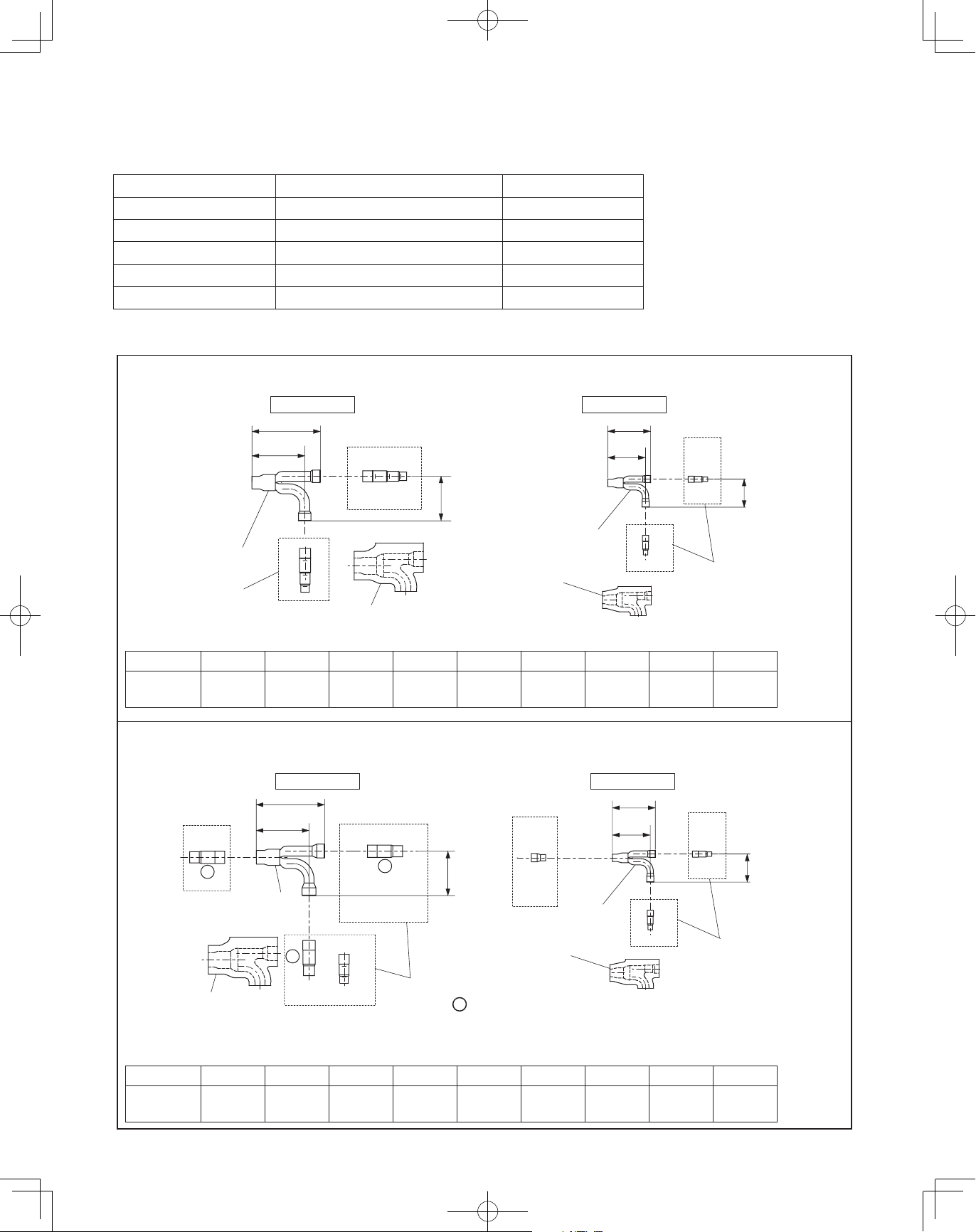
1-12. Optional Distribution Joint Kits
4-21/64
2-53/64
2-53/64
6-57/64
4-21/64
See the installation instructions packaged with the distribution joint kit for the installation procedure.
Table 1-12
Model name Cooling capacity after distribution Remarks
1. CZ-P680PJ1U 232,000 BTU/h (68.0 kW) or less For outdoor unit
2. CZ-P1350PJ1U more than 232,000 BTU/h (68.0 kW) For outdoor unit
3. CZ-P160BK1U 76,400 BTU/h (22.4 kW) or less* For indoor unit
4. CZ-P680BK1U 232,000 BTU/h (68.0 kW) or less* For indoor unit
5. CZ-P1350BK1U more than 232,000 BTU/h (68.0 kW)* For indoor unit
Tubing size (with thermal insulation)
n
1. CZ-P680PJ1U
For outdoor unit (Capacity after distribution joint is 232,000 BTU/h (68.0 kW) or less.)
Example:
Distribution
Joint
Reducing
Joints
Gas tubing Liquid tubing
6-59/64
(175)
5-5/16
(135)
C
C
Insulation
4-31/64
(114)
F E D C
Insulation
G
Distribution
Joint
* In case the total capacity of indoor
(110)
3-13/16
(97)
G
G
H
I
units connected after distribution
exceeds the total capacity of the
outdoor units, select the distribution
tube size for the total capacity of the
outdoor units.
HI
(72)
Reducing
Joints
Unit: in. (mm)
Table 1-13 Size of connection point on each part (Shown are inside diameters of tubing)
Size Part A Part B Part C Part D Part E Part F Part G Part H Part I
in. (mm)
ø1-3/8"
(ø34.92)
ø1-1/4"
(ø31.75)
ø1-1/8"
(ø28.58)
ø1"
(ø25.4)
ø7/8"
(ø22.22)
ø3/4"
(ø19.05)
ø5/8"
(ø15.88)
ø1/2"
(ø12.7)
2. CZ-P1350PJ1U
For outdoor unit (Capacity after distribution joint is greater than 232,000 BTU/h (68.0 kW).)
Example:
C
D
Insulation
With regard to the diameter of the tube without description in Table 1-14, use a reducer (field supply) to adjust the tube diameter.
*
B
A
Distribution
Joint
Gas tubing Liquid tubing
(175)
5-5/16
(135)
B
B
C
A
D
E
F
C
A
Reducing
Joints
D
4-31/64
(114)
: Outside dimension
F
Insulation
G
Distribution
Joint
(110)
3-13/16
(97)
G
H I
G
H
I
Reducing
Joints
Table 1-14 Size of connection point on each part (Shown are inside diameters of tubing)
ø3/4"
ø5/8"
(ø15.88)
ø1/2"
(ø12.7)
Size Part A Part B Part C Part D Part E Part F Part G Part H Part I
in. (mm)
ø1-3/8"
(ø34.92)
ø1-1/4"
(ø31.75)
ø1-1/8"
(ø28.58)
ø1"
(ø25.4)
ø7/8"
(ø22.22)
(ø19.05)
ø3/8"
(ø9.52)
(72)
Unit: in. (mm)
ø3/8"
(ø9.52)
13
00_302411_EN.indd 13 2018/7/4 13:27:18
Page 14
3. CZ-P160BK1U Use: For indoor unit (Capacity after distribution joint is 76,400 BTU/h (22.4 kW) or less.)*
4-21/64
4-21/64
2-53/64
6-57/64
2-53/64
2-53/64
6-57/64
Example:
A
Insulation
(110)
3-13/16 3-13/16
(97)
B
Distribution
Joint
B
B
C
Gas tubing
C
A
(72)
2-53/64
D
Insulation
(110)
(97)
C
Distribution
Joint
C
C
D
E
Liquid tubing
D E
Unit: in. (mm)
(72)
Table 1-15 Size of connection point on each part (Shown are inside diameters of tubing)
Size Part A Part B Part C Part D Part E
in. (mm)
ø3/4"
(ø19.05)
ø5/8"
(ø15.88)
ø1/2"
(ø12.7)
ø3/8"
(ø9.52)
ø1/4"
(ø6.35)
4. CZ-P680BK1U Use: For indoor unit (Capacity after distribution joint is greater than 76,400 BTU/h (22.4 kW) and no more
than 232,000 BTU/h (68.0 kW).)*
Example:
D C B
Insulation
A
Distribution
Joint
(175)
5-5/16
(135)
A
Gas tubing
4-31/64
A
B
C
D
E
F
B C D
Reducing
Joints
E F
(114)
F G
Distribution
Joint
Insulation
4-21/64
(110)
3-13/16
(97)
E
E
F
G
H
E
Liquid tubing
(72)
F G H
Reducing
Joints
Unit: in. (mm)
Table 1-16 Size of connection point on each part (Shown are inside diameters of tubing)
Size Part A Part B Part C Part D Part E Part F Part G Part H
in. (mm)
ø1-1/8"
(ø28.58)
ø1"
(ø25.4)
ø7/8"
(ø22.22)
ø3/4"
(ø19.05)
ø5/8"
(ø15.88)
ø1/2"
(ø12.7)
ø3/8"
(ø9.52)
ø1/4"
(ø6.35)
5. CZ-P1350BK1U Use: For indoor unit (Capacity after distribution joint is greater than 232,000 BTU/h (68.0 kW).)*
G
ø5/8"
(ø15.88)
4-21/64
(110)
3-13/16
(97)
G
H
I
J
G
ø1/2"
(ø12.7)
Liquid tubing
F
H
Reducing
Joints
Unit: in. (mm)
ø3/8"
(ø9.52)
(72)
Example:
A
C D
Insulation
*
With regard to the diameter of the tube without description in Table 1-17, use a reducer (field supply) to adjust the tube diameter.
Table 1-17 Size of connection point on each part (Shown are inside diameters of tubing)
Size Part A Part B Part C Part D Part E Part F Part G Part H Part I Part J
in. (mm)
ø1-3/8"
(ø34.92)
(175)
5-5/16
(135)
B
Distribution
Joint
C
D
E
F
G
H
ø1-1/4"
(ø31.75)
B
B
A
ø1-1/8"
(ø28.58)
Gas tubing
Reducing
Joints
ø1"
(ø25.4)
C D
A
4-31/64
(114)
: Outside dimension
ø7/8"
(ø22.22)
ø3/4"
(ø19.05)
F
Distribution
Joint
Insulation
In case the total capacity of indoor units connected after distribution exceeds the total capacity of the outdoor units, select the
distribution tube size for the total capacity of the outdoor units.
14
ø1/4"
(ø6.35)
00_302411_EN.indd 14 2018/7/4 13:27:18
Page 15
1-13. Example of Tubing Size Selection and Refrigerant Charge Amount
CAUTION
Additional refrigerant charging
Based on the values in Tables 1-3, 4, 5, 7, 10-1 and 10-2, use the liquid tubing size and length, and calculate the amount of
additional refrigerant charge using the formula below.
Unit of account (oz)
Required additional
refrigerant charge (oz)
or
g
Unit of account (
)
Required additional
refrigerant charge (g)
(a) : Liquid tubing Total length of ø7/8" (ft.) or (m) (d) : Liquid tubing Total length of ø1/2" (ft.) or (m)
(b) : Liquid tubing Total length of ø3/4" (ft.) or (m) (e) : Liquid tubing Total length of ø3/8" (ft.) or (m)
(c) : Liquid tubing Total length of ø5/8" (ft.) or (m) (f) : Liquid tubing Total length of ø1/4" (ft.) or (m)
Charging procedure
●
Be sure to charge with R410A refrigerant in liquid form.
1. After performing a vacuum, charge with refrigerant from the liquid tubing side.
At this time, all valves must be in the “fully closed” position.
2. If it was not possible to charge the designated amount, operate the system in Cooling mode while charging with refrigerant
from the gas tubing side. (This is performed at the time of the test run. For this, all valves must be in the “fully open” position.
However, if only one outdoor unit is installed, a balance tube is not used. Therefore, leave the valves fully closed.)
Charge with R410A refrigerant in liquid form.
With R410A refrigerant, charge while adjusting the amount being fed a little at a time in order to prevent liquid refrigerant from
backing up.
After charging is completed, turn all valves to the “fully open” position.
●
Replace the tubing covers as they were before.
●
CAUTION
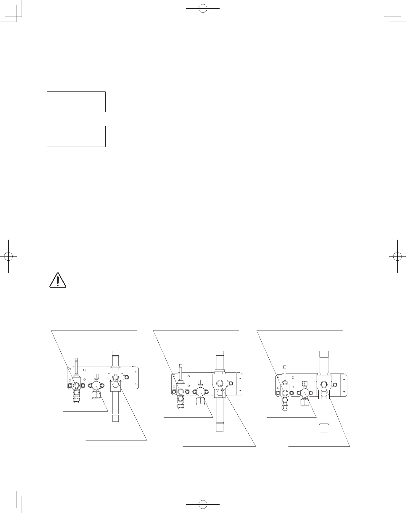
For type 72 For type 96 For type 120/144
Balance tube
Use a flathead screwdriver and
open by turning the part with the
screw groove to the right, from “–”
to “|”.
Necessary Amount of Additional Refrigerant Charge Per Outdoor Unit
=
+ 3.93 × (a) + 2.78 × (b) + 1.99 × (c) + 1.38 × (d) + 0.602 × (e) + 0.279 × (f)
+ Necessary amount of additional refrigerant charge for all indoor unit cooling capacity
Necessary Amount of Additional Refrigerant Charge Per Outdoor Unit
=
+ 366 × (a) + 259 × (b) + 185 × (c) + 128 × (d) + 56 × (e) + 26 × (f)
+ Necessary amount of additional refrigerant charge for all indoor unit cooling capacity
1. R410A additional charging absolutely must be done through liquid charging.
2. The R410A refrigerant cylinder has a gray base color, and the top part is pink.
3. The R410A refrigerant cylinder includes a siphon tube. Check that the siphon tube is present.
(This is indicated on the label at the top of the cylinder.)
4. Due to differences in the refrigerant, pressure, and refrigerant oil involved in installation, it is
not possible in some cases to use the same tools for R22 and for R410A.
Balance tube
Use a flathead screwdriver and
open by turning the part with the
screw groove to the right, from “–”
to “|”.
Balance tube
Use a flathead screwdriver and
open by turning the part with the
screw groove to the right, from “–”
to “|”.
Liquid tube
Use a hex wrench
(width 5/32 inch (4mm))
and turn to the left to
open.
Gas tube
Use a flathead screwdriver and
open by turning the part with the
screw groove to the right, from “–”
to “|”.
Liquid tube
Use a hex wrench
(width 5/32 inch (4mm))
and turn to the left to
open.
Gas tube
Use a flathead screwdriver and
open by turning the part with the
screw groove to the right, from “–”
to “|”.
Liquid tube
Use a hex wrench
(width 5/32 inch (4mm))
and turn to the left to
open.
Gas tube
Use a flathead screwdriver and
open by turning the part with the
screw groove to the right, from “–”
to “|”.
15
00_302411_EN.indd 15 2018/7/4 13:27:19
Page 16
Example:
Outdoor unit
Type 96 Type 72
B
Example of all outdoor units
●
cooling capacity
Type 72: 72,000 BTU/h (21.1 kW)
Type 96: 96,000 BTU/h (28.1 kW)
[Total]
A
LA
168,000 BTU/h (49.2 kW)
LB
1 2 3 4
LC
Example of each tubing length
●
Main tubing Distribution joint tubing
LA = 131 ft. (40m) Outdoor side Indoor side
LB = 16 ft. (4.9m)
LC = 16 ft. (4.9m)
A = 7 ft.
B = 7 ft.
(2.1m)
(2.1m)
1 = 98 ft.
2 = 16 ft.
3 = 16 ft.
4 = 65 ft.
Example of all indoor unit cooling capacity
●
(30m)
(4.9m)
(4.9m)
(19.8m)
[Type 48 x 3] 47,800 x 3 = 143,400 BTU/h (14.0 x 3 = 42.0 kW)
Type 48 Type 48 Type 48 Type 36
[Type 36 x 1] 36,000 x 1 = 36,000 BTU/h (10.6 x 1 = 10.6 kW)
[Total] 179,400 BTU/h (52.6 kW)
Obtain liquid tubing size from Tables 1-3, 4, 5, 7 and 10-1.
●
Main tubing
LA = ø5/8 (in.) (Total capacity of indoor unit is 179,400 BTU/h (52.6kW))
LB = ø1/2 (in.) (Total capacity of indoor unit is 131,600 BTU/h (38.6kW))
LC = ø3/8 (in.) (Total capacity of indoor unit is 83,800 BTU/h (24.6kW))
Distribution joint tubing
Outdoor side
Indoor side
Obtain additional charge amount for each tubing size and additional refrigerant charge amount for all indoor unit cooling capacity.
●
A: ø3/8 (in.) B: ø3/8 (in.) (from outdoor unit connection tubing)
1: ø3/8 (in.) 2: ø3/8 (in.) 3: ø3/8 (in.) 4: ø3/8 (in.) (from indoor unit connection tubing)
Note 1: The charge amounts per 1 ft. are different for each liquid tubing size.
ø5/8 (in.)
ø1/2 (in.)
ø3/8 (in.)
LA : 131 ft. × 1.99 oz/ft. = 261 oz (40m × 185 g/m = 7,400g)
→
LB : 16 ft. × 1.38 oz/ft. = 22 oz (4.9m × 128 g/m = 627g)
→
→
LC +
A – B + 1 – 4
: 225 ft. × 0.602 oz/ft. = 135 oz (68.6m × 56 g/m = 3,842g)
Total 418 oz (Total 11,869g)
Additional refrigerant charge amount is 418 oz (11,869g).
Note 2: Necessary amount of additional refrigerant charge per outdoor unit is 141oz (4,000g) in combination of 2 units.
(See the Table 1-10-2.)
Note 2) Amount of additional charge for outdoor unit (combination number) : 141oz (4,000g)
Note 3: Necessary amount of additional refrigerant charge for all indoor unit cooling capacity
[BTU/h] [kW]
179,400 BTU/h
Cooling capacity (BTU/h) x 1.034 x 0.001 + 10.6 oz
= 179,400 x 1.034 x 0.001 + 10.6 = 196 oz
(52.6 kW)
(Cooling capacity (kW) x1000 x 0.1 + 300
= 52.6 x 1000 x 0.1 + 300 = 5,560 g)
g
Note 1) Amount of additional charge per tubing length : 418 oz (11,869g)
Note 2) Amount of additional charge for outdoor unit (combination number) : 141 oz (4,000g)
Note 3) Amount of additional charge for all indoor unit cooling capacity : 196 oz (5,560g)
Total of additional refrigerant charge amount : 755 oz (21,429g)
Therefore, the total of additional refrigerant charge amount reaches 755 oz (21,429g).
Obtain overall refrigerant charge amount.
●
Overall refrigerant charge amount of the system indicates the calculated value shown above the additional charge amount in
addition to the total refrigerant charge amount (shown in the Table 1-6) at shipment in total cooling capacity of outdoor unit.
Refrigerant charge amount at shipment
(total cooling capacity of outdoor unit) : : [168,000BTU/h] 684 oz [49.2kW] (19,400g)
Total of additional refrigerant charge amount
:
755 oz (21,429g)
Grand total 1,439 oz (40,829g)
Therefore, overall refrigerant charge amount of the system reaches 1,439 oz (40,829g).
Remark:
Be sure to include the values in Table 1-10-2 Necessary Amount of Additional Refrigerant Charge Per Outdoor Unit.
CAUTION
Be sure to check the limit density for the room in which the indoor unit is installed.
16
00_302411_EN.indd 16 2018/7/4 13:27:19
Page 17
2. SELECTING THE INSTALLATION SITE
CAUTION
2-1. Outdoor Unit
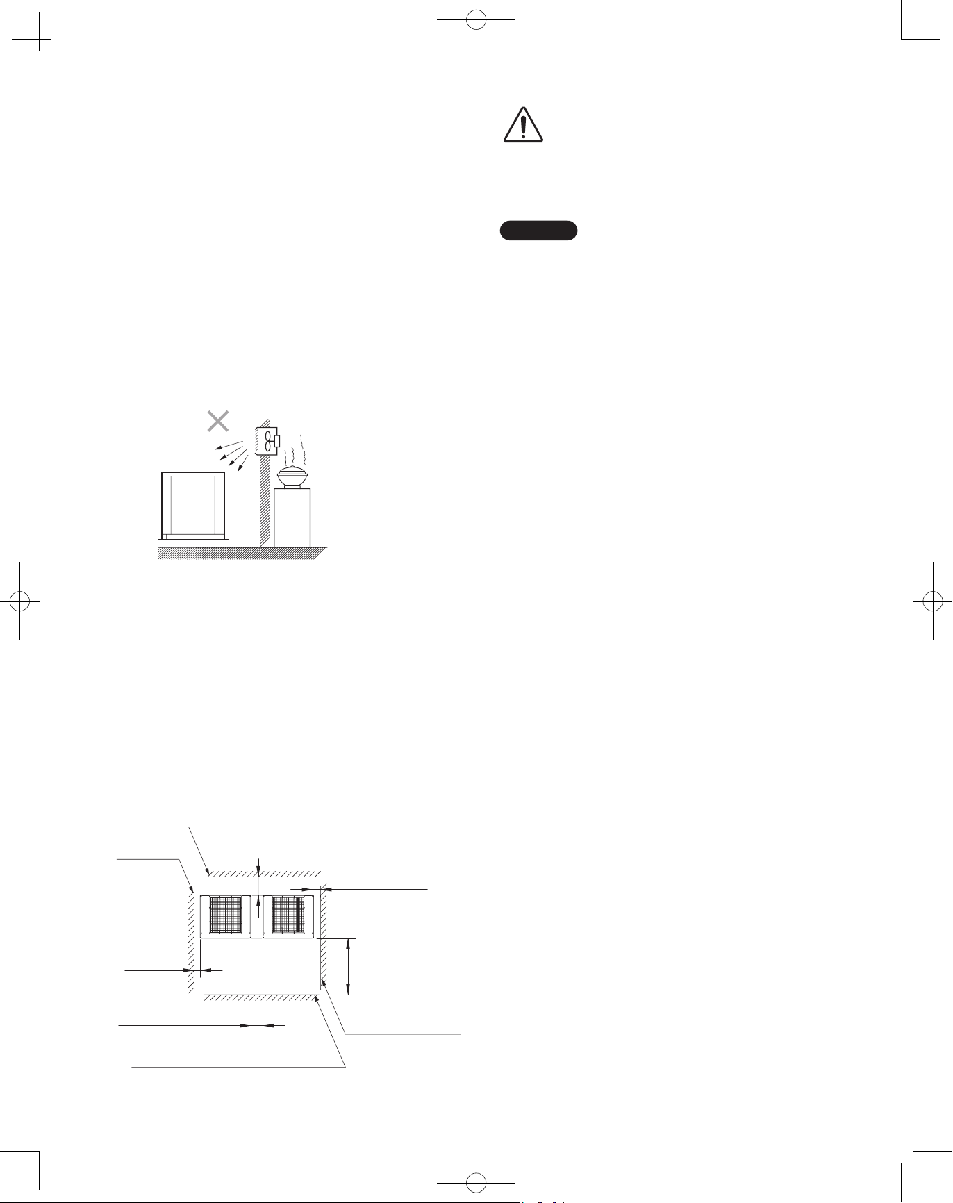
AVOID:
heat sources, exhaust fans, etc.
●
damp, humid or uneven locations
●
indoors (no-ventilation location)
●
DO:
choose a place as cool as possible.
●
choose a place that is well ventilated.
●
allow enough room around the unit for air intake/exhaust
●
and possible maintenance.
use lug bolts or equal to bolt down unit, reducing vibration
●
and noise.
Exhaust fan
Hot air
Heat
Out-
door
unit
Installation Space
Install the outdoor unit where there is enough space for
ventilation. Otherwise the unit may not operate properly.
The figure shows the minimum space requirement around
the outdoor units when 3 sides are open and only 1 side is
shuttered, with open space above the unit. The mounting
base should be concrete or a similar material that allows for
adequate drainage. Make provisions for anchor bolts, platform
height, and other site-specific installation requirements.
source
Leave space open above the
CAUTION
●
unit.
Construct louvers or other
●
openings in the wall, if
necessary, to ensure adequate
ventilation.
NOTE
Do not do any wiring or tubing within 1 ft. (300mm) of the
●
front panel, because this space is needed as a servicing
space for the compressor.
Ensure a base height of 4 in. (100mm) or more to ensure
●
that drainage water does not accumulate and freeze
around the bottom of the unit.
If installing a drain pan, install the drain pan prior to
●
installing the outdoor unit.
* Make sure there is at least 6 in. (150mm) between the
outdoor unit and the ground.
Also, the direction of the tubing and electrical wiring should
be from the front of the outdoor unit.
* When setting the anchor bolt to "B" or "C" (see page 20),
make enough space for installation operation.
(Space between units: Over 0.6 ft. (180mm), Space from
wall: Over 0.83 ft. (250mm))
* When installing a snow-proof ducting, make space between
the units 7-3/32 in. (180mm) regardless of the positions (A C) for installation holes.
* Make a walk-in space in front and behind the unit to ensure
ease of operation.
Example: 2 units installation
* For other installation, follow the standards of combination
installation.
Wall height: Less than 1.7ft. (500mm)
Wall height:
Unlimited
* Over 2 in.
(50mm)
Over 2-3/8 in. (60mm)
Wall height: Less than 4.9 ft. (1500mm)
Over 1 ft.(300mm)
* Over 2 in. (50mm)
Over 1.7ft. (500mm)
Wall height: Unlimited
17
00_302411_EN.indd 17 2018/7/4 13:27:19
Page 18
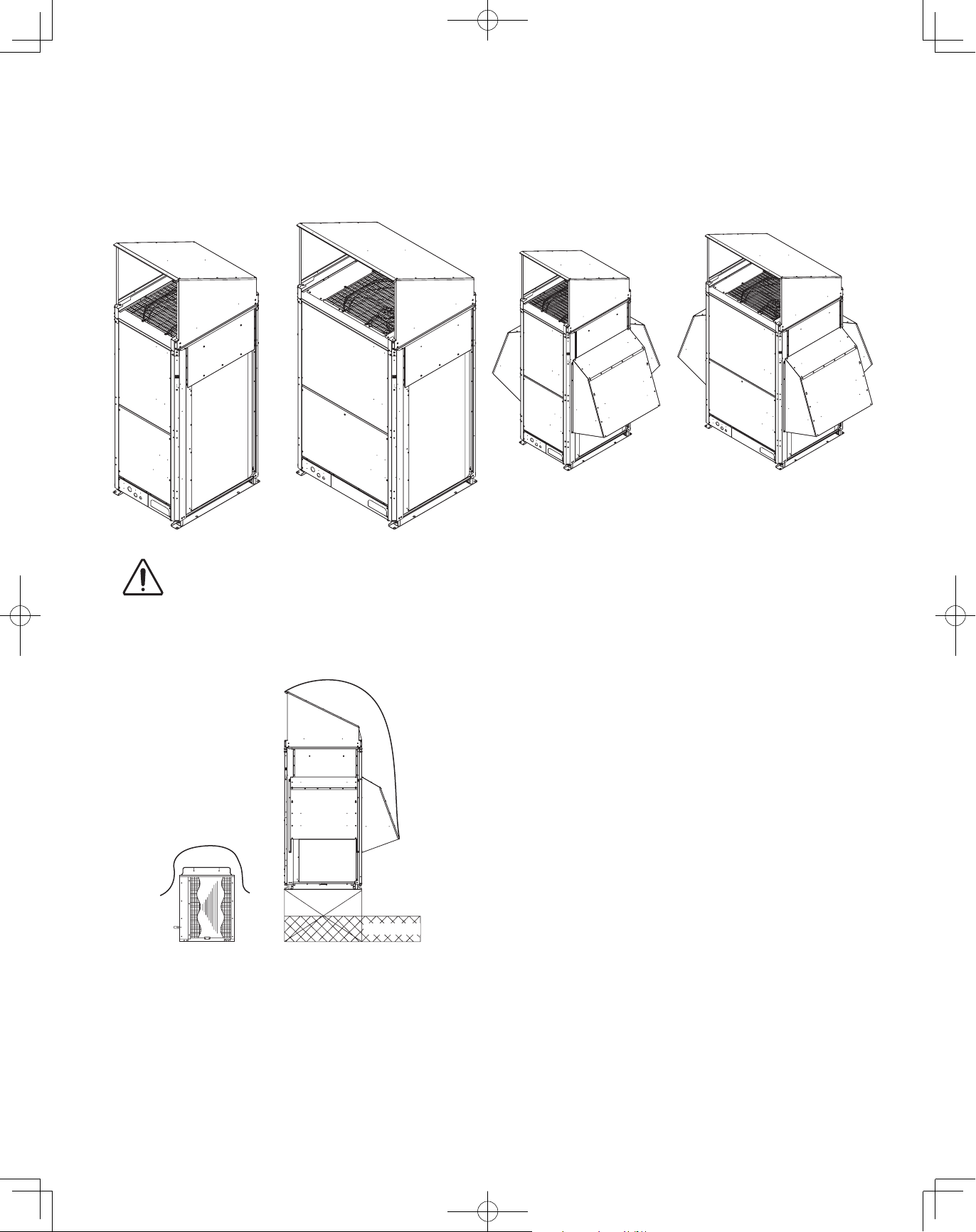
2-2. Shield for Horizontal Exhaust Discharge
CAUTION
It is necessary to install an air-discharge chamber (field
supply) to direct exhaust from the fan horizontally if it is difficult
to provide a minimum space of 7 ft. (2m) between the airdischarge outlet and a nearby obstacle.
In regions with heavy snowfall,
CAUTION
the outdoor unit should be
provided with a solid, raised
platform and snow-proof
ducting (field supply).
DO
2-3. Installing the Outdoor Unit in Heavy Snow
Areas
In locations where wind-blown snow can be a problem,
snow-proof ducting (field supply) should be fitted to the unit
and direct exposure to the wind should be avoided as much as
possible.
The following problems may occur if proper countermeasures
are not taken:
The fan in the outdoor unit may stop running, causing the
●
unit to be damaged.
There may be no air flow.
●
The tubing may freeze and burst.
●
The condenser pressure may drop because of strong wind,
●
and the indoor unit may freeze.
AVOID
Without snowproof ducting
(Without platform)
2-4. Precautions When Installing in Heavy Snow
Areas
a) The platform should be higher than the maximum snow
depth.
b) The 2 anchoring feet of the outdoor unit should be used for
the platform, and the platform should be installed beneath
the air-intake side of the outdoor unit.
c) The platform foundation must be solid and the unit must be
secured with anchor bolts.
d) When installing on a roof subject to strong wind,
countermeasures must be taken to prevent the unit from
being overturned.
Fallen snow
With snowproof ducting
(High platform)
18
00_302411_EN.indd 18 2018/7/4 13:27:22
Page 19
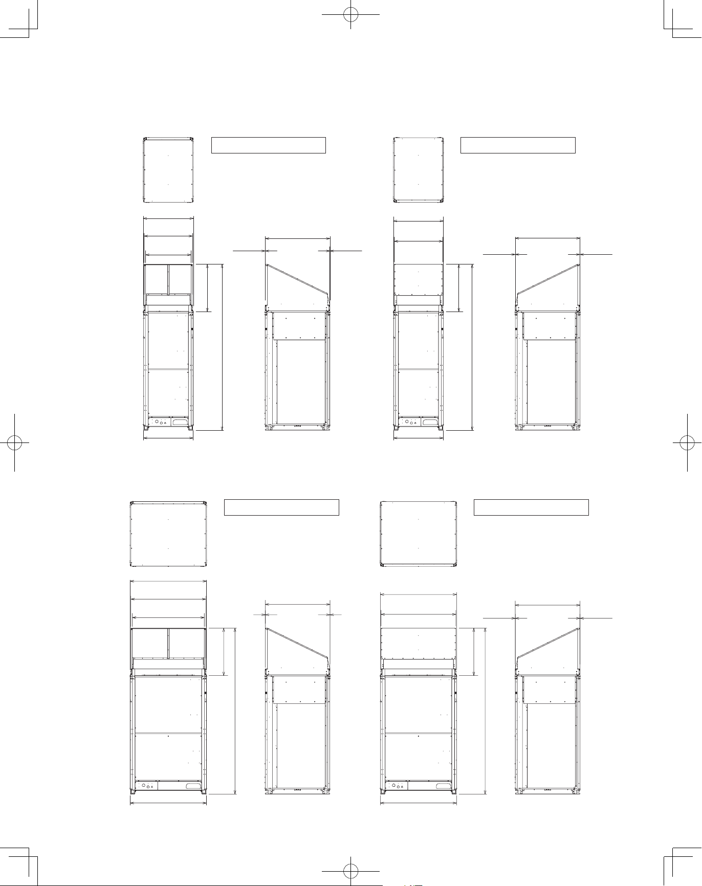
2-5. Dimensions of Wind Ducting
Reference diagram for air-discharge chamber (field supply)
For type 72/96
Note: Can be installed so that the air direction is to the front or rear direction.
unit: in. (mm)
Air direction: Front direction
30-35/64
(776)
29-29/64
(748)
27-43/64
(703)
(733)
28-55/64
(2570)
101-3/16
30-5/16
(770) (770)
Front view Right side view Front view Right side view
39-31/64
(1003)
5/64 (2)3/64 (1)
For type 120/144
Note: Can be installed so that the air direction is to the front or rear direction.
30-35/64
(776)
29-29/64
(748)
30-5/16
Air direction: Rear direction
Top viewTop view
39-31/64
(733)
28-55/64
(2570)
101-3/16
(1003)
unit: in. (mm)
3/64 (1)5/64 (2)
Air direction: Front direction
46-11/16
(1186)
45-19/32
(1158)
43-13/16
(1113)
46-29/64
(1180)
Front view Right side view Front view Right side view
3/64 (1)
(733)
28-55/64
(2570)
101-3/16
39-31/64
(1003)
5/64 (2)
46-11/16
(1186)
45-19/32
(1158)
46-29/64
(1180)
Air direction: Rear direction
Top viewTop view
39-31/64
5/64 (2)
(733)
28-55/64
(2570)
101-3/16
(1003)
19
3/64 (1)
00_302411_EN.indd 19 2018/7/4 13:27:24
Page 20
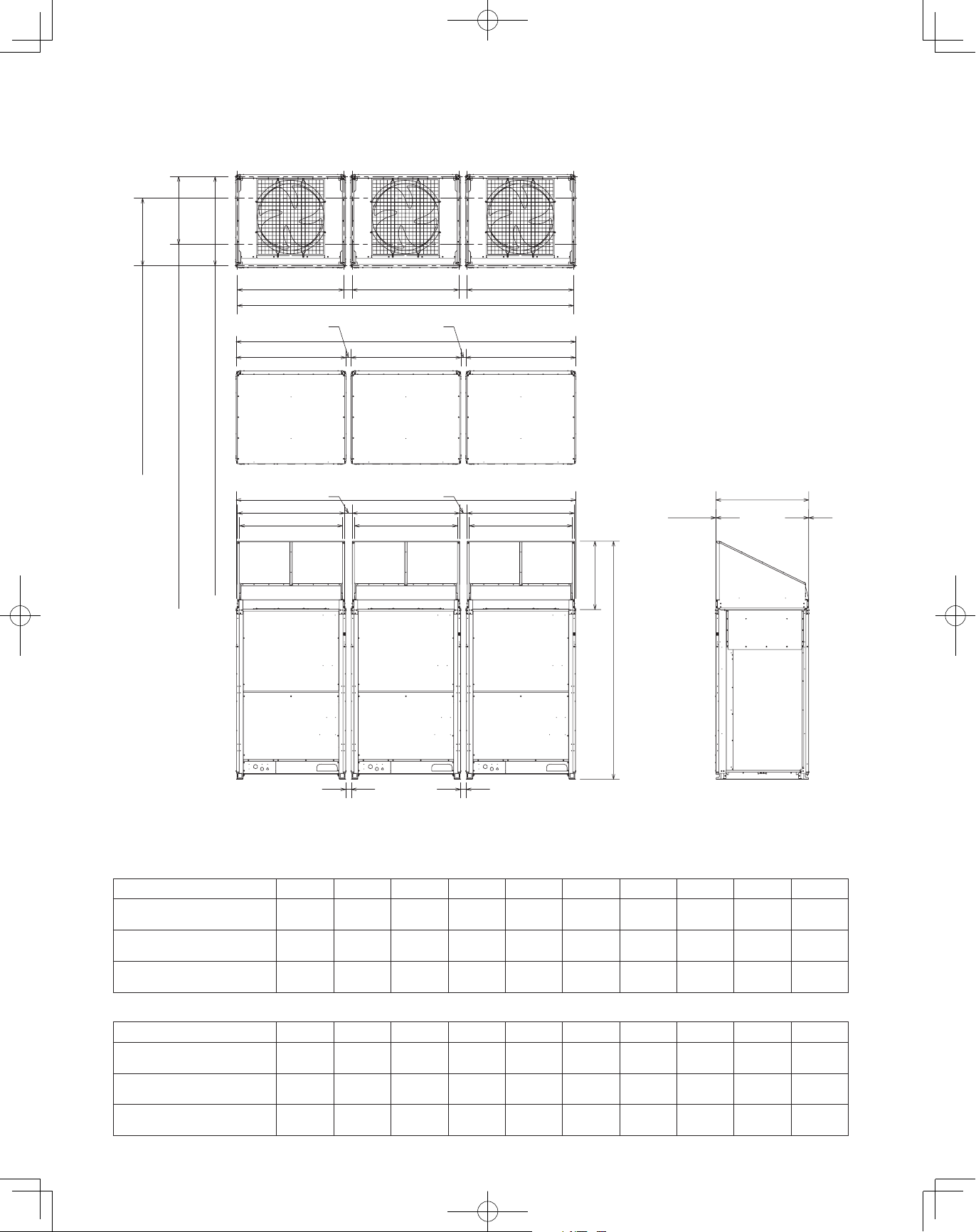
Reference diagram for air-discharge chamber (field supply) (continued)
Combination of units
For various types of combination, refer to Technical Data.
unit: in. (mm)
Top view
(Before installing air-discharge chamber)
J
K
C : 28-47/64 (730) Installation hole pitch
L
M
A : 37-61/64 (964) Installation hole pitch forward tubing direction
B : 28-47/64 (730) Installation hole pitch downward tubing direction
G
E
I I
J
H
F
K
F
L
M
G
E
J
K
Top view
39-31/64
L
M
(733)
28-55/64
(2570)
101-3/16
3/64 (1) 5/64 (2)
(1003)
D
Front view Right side view
According to the installation site, you may choose the setting position in the depth direction of the anchor bolt from “A”, “B” or “C”.
D
Sample of small size models (3 units):
D E F G H I J K L M
Installation hole pitch
A :
B :
Installation hole pitch
C :
Installation hole pitch
2-23/64
(60)
7-3/32
(180)
7-3/32
(180)
2-1/8
(54)
6-27/32
(174)
6-27/32
(174)
95-29/32
(2,436)
105-23/64
(2,676)
105-23/64
(2,676)
3-35/64
(90)
8-17/64
(210)
8-17/64
(210)
94-31/64
(2,400)
103-15/16
(2,640)
103-15/16
(2,640)
3-15/64
(82)
7-61/64
(202)
7-61/64
(202)
29-9/64
(740)
29-9/64
(740)
29-9/64
(740)
30-35/64
(776)
30-35/64
(776)
30-35/64
(776)
29-29/64
29-29/64
29-29/64
Sample of middle size models (3 units):
D E F G H I J K L M
Installation hole pitch
A :
B :
Installation hole pitch
C :
Installation hole pitch
2-23/64
(60)
7-3/32
(180)
7-3/32
(180)
2-1/8
(54)
6-27/32
(174)
6-27/32
(174)
144-21/64
(3,666)
153-25/32
(3,906)
153-25/32
(3,906)
3-35/64
(90)
8-17/64
(210)
8-17/64
(210)
142-29/32
(3,630)
152-23/64
(3,870)
152-23/64
(3,870)
3-15/64
(82)
7-61/64
(202)
7-61/64
(202)
45-9/32
(1,150)
45-9/32
(1,150)
45-9/32
(1,150)
46-11/16
(1,186)
46-11/16
(1,186)
46-11/16
(1,186)
45-19/32
(1,158)
45-19/32
(1,158)
45-19/32
(1,158)
20
(748)
(748)
(748)
27-43/64
(703)
27-43/64
(703)
27-43/64
(703)
43-13/16
(1,113)
43-13/16
(1,113)
43-13/16
(1,113)
00_302411_EN.indd 20 2018/7/4 13:27:27
Page 21

2-6. Dimensions of Snow Ducting
26-7/64
26-7/64
57-9/16
42-1/4
57-9/16
Reference diagram for snow-proof ducting (field supply)
For type 72/96
Note: Can be installed so that the air direction is to the front or rear direction.
(663)
Air direction: Front direction
(663)
unit: in. (mm)
Air direction: Rear direction
(872)
34-21/64
(74)
2-29/32
19-1/4
(489)
(1462)
(655)
25-25/32
(478)
18-13/16
For type 120/144
(872)
34-21/64
30-35/64
(776)
29-29/64
(748)
27-43/64
(703)
19-1/4
(489)
30-5/16
(770)
68-13/64
(1748)
Front view Right side view Front view Right side view
Note: Can be installed so that the air direction is to the front or rear direction.
(1073)
3/64 (1) 5/64 (2)
(733)
28-55/64
(2570)
101-3/16
Air direction: Front direction
39-31/64
(1003)
58-5/8
(1489)
19-1/4
(489)
18-13/16
(478)
25-25/32
57-9/16
(655)
(1462)
30-35/64
(776)
29-29/64
(748)
42-1/4
(1073)
Top viewTop view
39-31/64
5/64 (2) 3/64 (1)
Air direction: Rear direction
(1003)
unit: in. (mm)
19-1/4
(489)
(872)
34-21/64
(74)
2-29/32
19-1/4
(489)
(1462)
(655)
25-25/32
18-13/16
46-11/16
(1186)
45-19/32
(1158)
43-13/16
(1113)
(733)
28-55/64
19-1/4
(489)
101-3/16
(478)
46-29/64
(1180)
84-61/64
(2158)
Front view Right side view Front view Right side view
39-31/64
(1003)
(2570)
58-5/8
(1489)
5/64(2)3/64(1)
19-1/4
(489)
18-13/16
(478)
25-25/32
21
34-21/64
(1462)
57-9/16
(655)
(872)
46-11/16
(1186)
45-19/32
(1158)
Top viewTop view
39-31/64
(1003)
3/64(1)5/64(2)
19-1/4
(489)
00_302411_EN.indd 21 2018/7/4 13:27:35
Page 22

Reference diagram for snow-proof ducting (field supply) (continued)
8-17/64 (210) 8-17/64 (210)
Combination of units
For various types of combination, refer to Technical Data.
7-3/32 (180) 7-3/32 (180)
G
E
(872)
34-21/64
E
DD
H
unit: in. (mm)
E
D
Top view
(Before installing snow-proof ducting)
39-3/8
(1000)
Top view
(872)
34-21/64
F
7-61/64 (202)
(515)
20-9/32
(1466)
57-23/32
I
Front view Right side view
2-29/32 (74)
(1462)
57-9/16
(655)
25-25/32
35/64
(14)
19-1/4
(489)
(478)
18-13/16
C : 28-47/64 (730) Installation hole pitch
A : 37-61/64 (964) Installation hole pitch forward tubing direction
B : 28-47/64 (730) Installation hole pitch downward tubing direction
According to the installation site, you may choose the setting position in the depth direction of the anchor bolt from “A”, “B” or “C”.
7-61/64 (202)
(515)
20-9/32
57-23/32
(1466)
35/64 (14)
19-1/4
(489)
(478)
18-13/16
(74)
2-29/32
28-55/64
57-9/16
(655)
25-25/32
3/64 (1) 5/64 (2)
(733)
(2570)
101-3/16
(1462)
39-31/64
(1003)
Sample of small size models (3 units):
D E F G H I
A : Installation hole pitch
B : Installation hole pitch
C : Installation hole pitch
29-9/64
(740)
30-5/16
(770)
105-23/64
(2,676)
105-1/8
(2,670)
100-29/32
(2,563)
143-5/8
(3,648)
19-19/64
(490)
(478)
25-53/64
18-13/16
57-9/16
(656)
(1462)
Sample of middle size models (3 units):
D E F G H I
A : Installation hole pitch
B : Installation hole pitch
C : Installation hole pitch
45-9/32
(1,150)
46-29/64
(1,180)
153-25/32
(3,906)
153-35/64
(3,900)
149-21/64
(3,793)
192-3/64
(4,878)
22
00_302411_EN.indd 22 2018/7/4 13:27:42
Page 23

3. HOW TO INSTALL THE OUTDOOR UNIT
CAUTION
D
D
3-1. Transporting
When transporting the unit, have it delivered as close to the installation site as
possible without unpacking. Use a hook for suspending the unit.
●
CAUTION
When hoisting the outdoor unit, pass ropes or straps under the bottom plate
as shown in the figure at right. When hoisting, the angle between the rope
and top panel must be 70° or greater so that the rope does not come into
contact with the fan guard.
(Use 2 lengths of rope 25 ft. (approx. 7.6 m) long or more.)
When passing the ropes through the square holes of the bottom plate:
●
Place the rope in the outer edge of the square holes.
Use protective panels or padding at all locations where the rope
●
contacts the outer casing or other parts to prevent scratching.
In particular, use protective material (such as cloth or cardboard)
A A
Rope
to prevent the edges of the top panel from being scratched.
Be careful of the fan.
●
There is danger of injury if the fan starts to turn during inspection.
Be sure to turn OFF the remote power switch before beginning
inspection.
Detailed
drawing A
This is not a lifting lug.
<Do not attempt to lift the unit by one of the
legs at each corner of the unit or with hooks
or shackles attached for installing the legs.>
3-2. Installing the Outdoor Unit
(1) Use anchor bolts (15/32" or M12) or similar to securely anchor the unit in place.
(2) Make sure the rubber vibration insulator and platform extend to the inside of the legs. In addition, the washers used to anchor the
unit from the top must be larger than the installation anchor holes.
Type 120/144
D D
E E
H
Unit: in. (mm)
Vibration insulator Vibration insulator Vibration insulator
G
D D
F
A: 37-61/64 (964)
(Installation hole pitch)
D
E E
<Detailed view of legs>
2 support area per each leg (x2) must install vibration insulator material and mount.
The area of dimension marked with the asterisk (*) must cover the base.
Unit: in. (mm)
Vibration insulator
View F (area D/E) View G (area D) View H (area E)
Anchor bolt
Washer
19-32 (15)
*2-51/64 (71)
Base
Leg
Vibration insulator
4” (100)
Over
Leg
*3-15/16 (100)
Base
<Detailed view of installation holes>
Unit: in. (mm)
Installation elongated hole
(19/32 (15) x 53/64(21))
45/64 (18)
9-59/64 (252)
19/32 (15)
B: 28-47/64 (730)
Anchor bolt
Washer
4” (100)
Over
(Installation hole pitch)
D D
Anchor bolt
Vibration insulator
*3-15/16 (100)
Base
C: 28-47/64 (730)
(Installation hole pitch)
Unit: in. (mm)
Washer
4” (100)
23
00_302411_EN.indd 23 2018/7/4 13:27:42
Page 24

Type 72/96 Type 120/144
Air intake Air intake
Unit: in. (mm)
Air intake
39-3/8 (1000)
19/32 (15) 19/32 (15)
29-9/64 (740) 45-9/32 (1150)
(Installation hole pitch) (Installation hole pitch)
30-5/16 (770) 46-29/64 (1180)
A : 37-61/64 (964) [Installation hole pitch] * The tubing is routed out from the front.
B : 28-47/64 (730) [Installation hole pitch] * The tubing is routed out from the bottom.
C : 28-47/64 (730) [Installation hole pitch]
Air intake
B
C
A
39-3/8 (1000)
45/64 (18)
Air intake
Air intake
B
A
C
45/64 (18)
3-3. Routing the Tubing
The tubing can be routed out either from the front or from the bottom.
●
The connecting valve is contained inside the unit. Therefore, remove the front panel.
●
(1) If the tubing is routed out from the front, use cutting pliers or a similar tool to cut out the tubing outlet slit (part indicated by
from the tubing cover.
For type 72/96
Front
Bottom
For type 120/144 ex.) type72/96 (208/230 V model)
Tubing cover
Front
Bottom
Remove 3 screws
ex.) type 120/144 (208/230 V model)
Use cutting pliers or similar tool
to cut cover out
)
Remove 8 panel screws
from front panel
Remove 10 panel screws
from front panel
(2) If the tubing is routed out from the bottom, remove the slit part ( ).
Use a drill bit approximately 13/64" (5.2 mm) dia. to create holes at the
●
5 slit hole indentations (openings).
Punch out the slit part (
●
Be careful not to damage the base plate.
●
).
24
Tubing cover
Remove 4 screws
Use cutting pliers or similar tool
to cut cover out
Tubing cover
Slit hole
Tubing cover
Slit part
Indentation (5 locations)
00_302411_EN.indd 24 2018/7/4 13:27:43
Page 25

3-4. Prepare the Tubing
CAUTION
1
2
1
2
2
3
2
3
Material: Use seamless phosphorous deoxidized copper tube for refrigeration. Wall thickness shall comply with the applicable
●
legislation. The minimal wall thickness must be in accordance with the table below.
Tubing size
●
Use the tubing size indicated in the table below.
When cutting the tubing, use a tube cutter, and be sure to remove any burrs.
●
(The same applies to distribution tubing (optional).)
When bending the tubes, bend each tube using a radius that is at least 4 times the outer diameter of the tube.
●
When bending, use sufficient care to avoid crushing or damaging the tube.
For flaring, use a flare tool, and be sure that flaring is performed correctly.
●
CAUTION
Use sufficient caution during preparation of the tubing. Seal the tube ends by means of caps or
taping to prevent dust, moisture, or other foreign substances from entering the tubes.
Refrigerant tubing (Existing tubing can be used.)
Tubing size (in. (mm))
Material: O Material: O
Outer diameter Wall thickness Outer diameter Wall thickness
1/4" (6.35) 0.025 (0.635) 7/8" (22.22) 0.045 (1.143)
3/8" (9.52) 0.030 (0.762) 1-1/8" (28.58) 0.050 (1.27)
1/2" (12.7) 0.035 (0.889) 1-3/8" (34.92) 0.055 (1.397)
5/8" (15.88) 0.040 (1.016) 1-5/8" (41.28) 0.060 (1.524)
3/4" (19.05) 0.042 (1.0668)
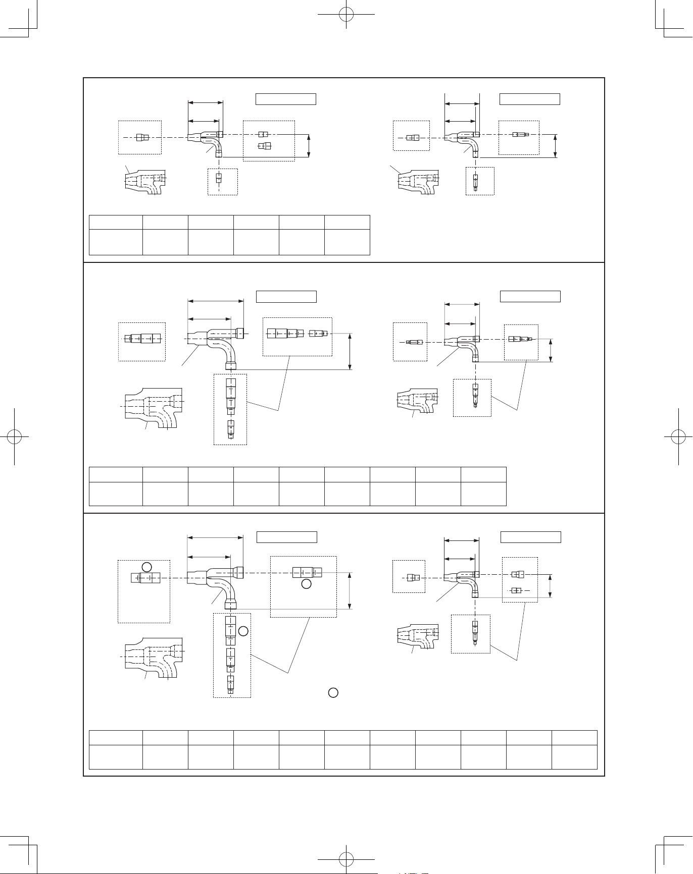
3-5. Connect the Tubing
Use the supplied connector tubing. (See figure below.)
●
Type 72 (6 Ton) Type 120 (10 Ton)
3
Refrigerant
tubing
1
Gas tube Brazing No
2
Liquid tube Flare No
3
Balance tube Flare No
Connection
method
Supplied
parts used?
3
Refrigerant
tubing
1
Gas tube Brazing
2
Liquid tube Flare No
3
Balance tube Flare No
Connection
method
(ø25.4 ø28.58)
Supplied
parts used?
Yes
ø1" ø1-1/8"
Type 96 (8 Ton) Type 144 (12 Ton)
1
Refrigerant
tubing
1
Gas tube Brazing No
2
Liquid tube Flare No
3
Balance tube Flare No
Connection
method
Supplied
parts used?
1
Refrigerant
tubing
1
Gas tube Brazing
2
Liquid tube Flare No
3
Balance tube Flare No
Connection
method
Supplied
parts used?
Yes
ø1" ø1-1/8"
(ø25.4 ø28.58)
25
00_302411_EN.indd 25 2018/7/4 13:27:44
Page 26

Refrigerant tube port
Use caulking, putty, or a similar material to fill any gaps at the
●
refrigerant tube port (
) in order to prevent rainwater, dust or
foreign substances from entering the unit.
* Perform this work even if the tubing is routed out in a downward
direction.
Tighten each cap as specified below.
●
Tightening torque for each cap
Cap tightening torque
Width unit: lbs · inch unit: N · m unit: {kgf · cm}
Service port cap 43/64" (17mm) 90 - 100 10 - 12 {100 - 120}
Valve cap
35/64" (14mm),
43/64" (17 mm)
3/4" (19 mm) 120 - 170 14 - 20 {140 - 200}
17/16" (27mm) 190 - 240 22 - 28 {220 - 280}
170 - 220 20 - 25 {200 - 250}
Tubing cover
Tubing routed out
through the front side
Bottom plate
Tubing routed out
through the bottom
For type 72
Service port cap
width 43/64 (17)
Valve cap
width 3/4 (19)
Valve cap
width 35/64 (14)
Service port cap
width 43/64 (17)
Flare nut
ø1/4 (6.35)
For type 120/144
Service port cap
width 43/64 (17)
Valve cap
width 17/16 (27)
Valve cap
width 35/64 (14)
Service port cap
width 43/64 (17)
Flare nut
ø1/4 (6.35)
Flare nut
ø3/8 (9.52)
Flare nut
ø1/2 (12.7)
Valve cap
width 35/64 (14)
Service port cap
width 43/64 (17)
Valve cap
width 43/64 (17)
Service port cap
width 43/64 (17)
For type 96
Service port cap
width 43/64 (17)
Valve cap
width 3/4 (19)
Valve cap
width 35/64 (14)
Service port cap
width 43/64 (17)
Flare nut
ø1/4 (6.35)
Unit: in. (mm)
Valve cap
width 43/64 (17)
Flare nut
ø3/8 (9.52)
Do not apply an adjustable wrench
to the hexagonal part.
Do not use two adjustable wrenches when removing or
installing the balance tube flare nut. In particular, do not
apply an adjustable wrench to the hexagonal part at the top
of the valve. (If force is applied to this part, gas leakage will
occur.)
Use two adjustable wrenches, as shown in the figure,
when removing the liquid tube valve flare nut.
1. Do not apply a wrench to the valve cap when
removing or installing the flare nuts.
Doing so may damage the valve.
2. If the valve cap is left off for a long period of time,
refrigerant leakage will occur.
Therefore, do not leave the valve cap off.
3. Applying refrigerant oil to the flare surface can be
effective in preventing gas leakage, however be
sure to use a refrigerant oil which is suitable for
the refrigerant that is used in the system. (This unit
utilizes R410A refrigerant, and the refrigerant oil is
ether oil (synthetic oil).
However, hub oil (synthetic oil) can also be used.)
Service port cap
width 43/64 (17)
26
00_302411_EN.indd 26 2018/7/4 13:27:45
Page 27

Precautions for brazing
CAUTION
●
Be sure to replace the air inside the tube with nitrogen to prevent oxide
film from forming during the brazing process. Be sure to use a damp cloth
or other means to cool the valve unit during brazing.
Work method
Brazing locations
CAUTION
Pressure-reducing
valve (regulator)
Field-supply tube
Taping
Remote valve
Nitrogen
1. Be sure to use nitrogen. (Oxygen, CO2, and CFC must not be used.)
2. Use a pressure-reducing valve on the nitrogen tank.
3. Do not use agents intended to prevent the formation of oxide film.
They will adversely affect the refrigeration oil, and may cause equipment failure.
4. The balance tube is not used if only 1 outdoor unit is installed.
Use the unit in the same conditions as when it was shipped from the factory.
27
00_302411_EN.indd 27 2018/7/4 13:27:45
Page 28

4. ELECTRICAL WIRING
CAUTION
4-1. General Precautions on Wiring
(1) Before wiring, confirm the rated voltage of the unit as
shown on its nameplate, then carry out the wiring closely
following the wiring diagram.
WARNING
(2) This equipment is strongly recommended to be
installed with Earth Leakage Circuit Breaker (ELCB)
or Residual Current Device (RCD). Otherwise,
it may cause electrical shock and fire in case of
equipment breakdown or insulation breakdown.
Provide a power outlet to be used exclusively for
each unit, and Earth Leakage Circuit Breaker
(ELCB) for overcurrent protection should be
provided in the exclusive line.
(3) To prevent possible hazards from insulation failure,
the unit must be grounded.
(4) Each wiring connection must be done in accordance with
the wiring system diagram. Wrong wiring may cause the
unit to misoperate or become damaged.
(5) Do not allow wiring to touch the refrigerant tubing,
compressor, or any moving parts of the fan.
(6) Unauthorized changes in the internal wiring can be very
dangerous. The manufacturer will accept no responsibility
for any damage or misoperation that occurs as a result of
such unauthorized changes.
(7) Regulations on wire diameters differ from locality to
locality. For field wiring rules, please refer to your LOCAL
ELECTRICAL CODES before beginning.
You must ensure that installation complies with all relevant
rules and regulations.
(8) To prevent malfunction of the air conditioner caused by
electrical noise, care must be taken when wiring as follows:
The remote control wiring and the inter-unit control wiring
●
should be wired apart from the inter-unit power wiring.
Use shielded wires for inter-unit control wiring between
●
units and ground the shield on both sides.
(9) If the power supply cord of this appliance is damaged,
it must be replaced by a repair shop appointed by the
manufacturer, because special purpose tools are required.
4-2. Recommended Wire Length and Wire Diameter for Power Supply System
Outdoor unit Indoor unit
Type
U-72ME2U9 50 A K2 15 A
U-96ME2U9 60 A
U-120ME2U9 60 A E1 15 A
U-144ME2U9 60 A
U-72ME2U94 25 A
U-96ME2U94 25 A
U-120ME2U94 25 A
U-144ME2U94 30 A
Control wiring
(A) Inter-unit (between outdoor and
indoor units) control wiring*
AWG #18 (0.75 mm2) AWG #18 (0.75 mm2) AWG #18 (0.75 mm2)
Max. 3,280 ft. (1,000 m) Max. 1,640 ft. (500 m) Max. 650 ft. (200 m) Total
Time delay fuse or
circuit capacity
(B) Remote control wiring (C) Control wiring for group control
Type
D1, U2, Y2, F2, M2, T2, P1, R1
Time delay fuse or
circuit capacity
15 A
(D) Inter-outdoor unit control wiring
2
NOTE
* With ring-type wire terminal.
28
00_302411_EN.indd 28 2018/7/4 13:27:45
AWG #18 (0.75 mm
Max. 980 ft. (300 m)
)
Page 29

4-3. Wiring System Diagram
*
Power supply
208 / 230V, 60Hz, 1-PH
Remote
Controller
WHT
1
BLK
2
Power supply
208 / 230V, 60Hz, 1-PH
Remote
Controller
1
WHT
2
BLK
Power supply
208 / 230V, 60Hz, 1-PH
Power supply
208 / 230V, 60Hz, 1-PH
Remote
Controller
WHT
1
2
BLK
L1
L2
Ground
1
2
L1
L2
Ground
1
2
Group control:
L1
L2
Ground
L1
L2
Ground
1
2
B
*
B
*
*
B
Indoor
unit (No. 1)
L1
L2
U1
U2
R1
R2
A
U-72ME2U9 / U-96ME2U9 / U-120ME2U9 / U-144ME2U9
Outdoor unit
INV unit
U1
U2
1
2
L1
L2
L3
*
L1
L2
L3
Power supply
208 / 230V, 60Hz, 3-PH
Ground
A
Indoor
unit (No. 2)
L1
L2
U1
U2
R1
R2
D
Inter-outdoor unit control wiring
Outdoor unit
INV unit
L1
L2
1
L3
2
*
L1
L2
L3
Power supply
208 / 230V, 60Hz, 3-PH
Ground
A
Indoor
unit (No. 3)
L1
L2
U1
C
U2
R1
R2
A
Indoor
unit (No. n)
L1
L2
U1
U2
R1
R2
U-72ME2U94 / U-96ME2U94 / U-120ME2U94 / U-144ME2U94
Outdoor unit
INV unit
L1
U1
L2
U2
L3
1
2
D
Inter-outdoor unit control wiring
Outdoor unit
INV unit
L1
L2
1
L3
2
*
L1
L2
L3
*
L1
L2
L3
Power supply
460V, 60Hz, 3-PH
Ground
Power supply
460V, 60Hz, 3-PH
Ground
* Disconnect switch (Field Supply)
* NOTE:
Disconnect Switch may be needed by the National/Local code.
NOTE
(1) See the section “4-2. Recommended Wire Length
and Wire Diameter for Power Supply System” for the
explanation of “A,” “B,” “C” and “D” in the above diagram.
(2) The basic connection diagram of the indoor unit shows
the 6P terminal board, so the terminal boards in your
equipment may differ from the diagram.
(3) Refrigerant Circuit (R.C.) address should be set before
turning the power on.
(4) Regarding the R.C. address setting, See the section “7-5.
Auto Address Setting”. Address setting can be executed
by remote controller automatically.
ALWAYS COMPLY WITH NATIONAL AND LOCAL CODE
REQUIREMENTS.
3P terminal board
L2 L3L1
2P terminal board (×2)
(U-72ME2U9 / U-96ME2U9 /
U-120ME2U9 / U-144ME2U9)
U1 1U2 2
Inter-unit
control wiring
Inter-outdoor unit
control wiring
Outdoor Unit
4P terminal board
(U-72ME2U94 / U-96ME2U94 /
U-120ME2U94 / U-144ME2U94)
U1 U2
Inter-unit
control wiring
1 2
Inter-outdoor unit
control wiring
29
00_302411_EN.indd 29 2018/7/4 13:27:45
Page 30

CAUTION
CAUTION
(1) When linking outdoor units in a network, disconnect the terminal extended from the short plug (CN67) from all outdoor
units except any one of the outdoor units. (When shipping: In shorted condition.)
For a system without link (no connection wiring between outdoor units), do not remove the short plug.
(2) Do not install the inter-unit control wiring in a way that forms a loop.
Outdoor unit
Indoor unit Indoor unit Indoor unit Indoor unit Indoor unit
Outdoor unit Outdoor unit
Prohibited
Prohibited
(3) Do not install inter-unit control wiring such as star branch
wiring. Star branch wiring causes mis-address setting.
Outdoor unit Indoor unit Indoor unit
Indoor unit Indoor unit
NO
Branch point
(4) If branching the inter-unit control wiring, the number of branch points should be 16 or fewer.
Outdoor unit
Central Controller
: Branch point
More than 7ft. (2m) required
Outdoor unit
Outdoor unit
Indoor unit
Indoor unit
Indoor unit
Indoor unit
Indoor unit
Indoor unit
Indoor unit
Indoor unit
Indoor unit
30
00_302411_EN.indd 30 2018/7/4 13:27:45
Page 31

CAUTION
WARNING
Loose wiring may cause the terminal to overheat or result in unit malfunction.
A fire hazard may also exist.
Therefore, ensure that all wiring is tightly connected.
When connecting each power wire to the terminal, follow the instructions on “How to connect wiring to the terminal” and fasten the
wire securely with the fixing screw of the terminal board.
How to connect wiring to the terminal
For stranded wiring
n
(1) Cut the wire end with cutting pliers, then strip the insulation
to expose the stranded wiring approx. 3/8" (10mm) and tightly
twist the wire ends.
(2) Using a Phillips head screwdriver, remove the terminal screw(s)
on the terminal board.
(3) Using a ring connector fastener or pliers, securely clamp each
stripped wire end with a ring pressure terminal.
(4) Place the ring pressure terminal, and replace and tighten the
removed terminal screw using a screwdriver.
Checking voltage of terminal board
Check if the wiring AC200V or more is connected to the inter-unit
control wiring connection terminal board.
First, turn off the power and then proceed the work.
If AC200V or higher voltage is mistakenly applied to the P.C. board,
the fuse (FUSE3, 0.4A) of outdoor control P.C. board is broken and
the P.C. board will be protected.
Special
washer
Wire
Stranded wire
Strip 3/8" (10mm)
Screw
Ring pressure
terminal
Terminal board
Wire
Ring
pressure
terminal
Screw and
Special washer
Ring
pressure
terminal
U-72ME2U9 / U-96ME2U9 / U-120ME2U9 / U-144ME2U9
In this case, reconnect the wires correctly and disconnect the 2P connector (BLU, OC, CN76) on P.C. board.
Then, replace that connector with the 2P connector (BRN, EMG, CN69).
Cut out the jumper (JP11).
U-72ME2U9 / U-96ME2U9
(CR-72ME2U9/A747841)
Jumper
JP11
EMG, CN69
2P connector,
BRN
OC, CN76
2P connector,
CN69CN76
OC
BLU
Fuse
FUSE3
JP11
EMG
FUSE3
U-120ME2U9 / U-144ME2U9
(CR-144ME2U9/A747593)
Jumper
JP11
EMG, CN69
2P connector,
BRN
JP11
CN69
OC, CN76
2P connector,
EMG
OC
CN76
BLU
FUSE3
Fuse
FUSE3
31
00_302411_EN.indd 31 2018/7/4 13:27:46
Page 32

U-72ME2U94 / U-96ME2U94 / U-120ME2U94 /
U-144ME2U94
In this case, replace the pins 1 and 2 of the 2P connector
(BRN, EMG, CN69) with the pins 2 and 3.
Cut out the jumper (JP11).
Wiring sample
n
U-72ME2U9 / U-96ME2U9 / U-120ME2U9 / U-144ME2U9
Type 72/96
Electronic component box
(CR-72ME2U94/ACXA73-03280)
Jumper
JP11
EMG, CN69
2P connector,
BRN
Fuse
FUSE3
Type 120/144
Type 72/96
Inter-unit control wiring (U1, U2)
2P terminal board *
Inter-outdoor unit control wiring (1, 2)
2P terminal board *
Terminal board for power supply
3P terminal board *
Earth terminal *
1
1
2
3
Tightening torque
lbs.inch N · m
*1 11
*2 55
*3 73
3 1.25 0.25
2 6.2 0.2
4 8.2 0.4
Fit wires with cable clamps.
Type 120/144
Fit power supply and Inter-unit
control wires with cable clamps
respectively (field supply).
32
00_302411_EN.indd 32 2018/7/4 13:27:48
Page 33

U-72ME2U94 / U-96ME2U94 / U-120ME2U94 / U-144ME2U94
Type 72/96 Type 120/144
Electronic component box
Inter-unit control wiring (U1, U2)
4P terminal board *
Inter-outdoor unit control wiring (1, 2)
4P terminal board *
Terminal board for power supply
3P terminal board *
1
1
2
P.C. boardP.C. board
Earth terminal *
3
Tightening torque
lbs.inch N · m
*1 11
*2 55
*3 73
1 1.30 0.1
2 6.2 0.2
4 8.2 0.4
Fit wires with cable clamps.
Fit power supply and Inter-unit
control wires with cable clamps
respectively (field supply).
Hollow to cut out opening *
4
Unit: in. (mm)
ø1-3/4" (ø44) (Power supply wiring inserting port: knockout holes)
Wiring panel
ø1-3/8" (ø35) (Power supply wiring inserting port: knockout holes)
(Front)
ø7/8" (ø23) (Inter-unit control wiring inserting port: knockout holes)
Hollow to cut out opening *
4
ø1-3/8" (ø35) (Power supply wiring inserting port: knockout holes)
ø7/8" (ø23) (Inter-unit control wiring inserting port: knockout holes)
Wiring panel
(Bottom)
ø1-3/4" (ø44) (Power supply wiring inserting port: knockout holes)
*4 ・ Hollow for jigsaw holes (Maximum allowed per hole is ø1-7/8" (ø48).)
・ Be sure to use waterproof conduit for electrical wiring to the outdoor unit.
・ Protective structure is necessary to avoid raindrops through wiring ports.
・ Hollow to cut out openings for wiring ports on the panel with a jigsaw.
33
00_302411_EN.indd 33 2018/7/4 13:27:49
Page 34

5. HOW TO PROCESS TUBING
The liquid tubing side is connected by a flare nut, and the gas
tubing side is connected by brazing.
5-1. Connecting the Refrigerant Tubing
(3) Remove the flare nut from the unit and be sure to mount it
on the copper tube.
(4) Make a flare at the end of copper tube with a flare tool.
Use of the Flaring Method
Many of conventional split system air conditioners employ the
flaring method to connect refrigerant tubes which run between
indoor and outdoor units. In this method, the copper tubes are
flared at each end and connected with flare nuts.
Flaring Procedure with a Flare Tool
(1) Cut the copper tube to the required length with a tube cutter.
It is recommended to cut approx. 1 – 2 ft. (0.3 - 0.6m) longer
than the tubing length you estimate.
(2) Remove burrs at the end of the copper tube with a tube
reamer or file. This process is important and should be done
carefully to make a good flare.
Deburring
Before After
Flare nut
Copper
tubing
Flare tool
NOTE
A good flare should have the following characteristics:
inside surface is glossy and smooth
●
edge is smooth
●
tapered sides are of uniform length
●
NOTE
When reaming, hold the tube end downward and be sure that no
copper scraps fall into the tube.
Copper
tubing
Reamer
34
00_302411_EN.indd 34 2018/7/4 13:27:49
Page 35

Caution Before Connecting Tubes Tightly
(1) Apply a sealing cap or water-proof tape to prevent dust or water from entering the
tubes before they are used.
(2) Be sure to apply refrigerant lubricant to the matching surfaces of the flare and union
before connecting them together. This is effective for reducing gas leaks.
(3) For proper connection, align the union tube and flare tube straight with each other,
then screw in the flare nut lightly at first to obtain a smooth match.
Adjust the shape of the liquid tube using a tube bender at the installation site and
●
connect it to the liquid tubing side valve using a flare.
Cautions During Brazing
Replace air inside the tube with nitrogen gas to prevent copper oxide film
●
from forming during the brazing process. (Oxygen, carbon dioxide and Freon
are not acceptable.)
Do not allow the tubing to get too hot during brazing.
●
The nitrogen gas inside the tubing may overheat, causing refrigerant system
valves to become damaged.
Therefore allow the tubing to cool when brazing.
Use a reducing valve for the nitrogen cylinder.
●
Do not use agents intended to prevent the formation of oxide film.
●
These agents adversely affect the refrigerant and refrigerant oil, and may
cause damage or malfunctions.
5-2. Connecting Tubing Between Indoor and Outdoor Units
Apply refrigerant
lubricant
Union Flare nut
Torque wrench
Spanner
Indoor unit
Outdoor unit
(1) Tightly connect the indoor-side refrigerant tubing
extended from the wall with the outdoor-side
tubing.
(2) To fasten the flare nuts, apply specified torque as at right:
When removing the flare nuts from the tubing
●
connections, or when tightening them after connecting the
tubing, be sure to use 2 adjustable wrenches or spanners
as shown.
If the flare nuts are over-tightened, the flare may be
damaged, which could result refrigerant leakage and
cause in injury or asphyxiation to room occupants.
For the flare nuts at tubing connections, be sure to use
●
the flare nuts that were supplied with the unit, or else flare
Tube
diameter
in. (mm)
ø1/4
(ø6.35)
ø3/8
(ø9.52)
ø1/2
(ø12.7)
ø5/8
(ø15.88)
ø3/4
(ø19.05)
Tightening torque, approximate Tube thickness
lbs · in. N · m {kgf · cm} inch mm
120 – 160 14 – 18 {140 – 180} 0.025 0.635
300 – 360 34 – 42 {340 – 420} 0.030 0.762
430 – 610 49 – 61 {490 – 610} 0.035 0.889
590 – 710 67 – 81 {680 – 820} 0.040 1.016
870 – 1040 99 – 118 {1000 – 1200} 0.042 1.0668
nuts for R410A (type 2).
The refrigerant tubing that is used must be of the correct
wall thickness as shown in the table at right.
Because the pressure is approximately 1.6 times higher than conventional refrigerant pressure, the use of ordinary flare nuts
(type 1) or thin-walled tubes may result in tube rupture, injury, or asphyxiation caused by refrigerant leakage.
In order to prevent damage to the flare caused by over-tightening of the flare nuts, use the table above as a guide when
●
tightening.
When tightening the flare nut on the liquid tube, use an adjustable wrench with a nominal handle length of 7-7/8" (200 mm).
●
35
00_302411_EN.indd 35 2018/7/4 13:27:50
Page 36

5-3. Insulating the Refrigerant Tubing
CAUTION
5-4. Taping the Tubes
Tubing Insulation
Thermal insulation must be applied to all unit tubing, including
●
the distribution joint (purchased separately).
How to arrange 2 tubes (between outdoor unit and indoor unit)
Liquid tubing
Insulation
Gas tubing
How to arrange 3 tubes (between outdoor units)
Cosmetic
(finishing) tape
Liquid tubing
Insulation
* For gas tubing, the insulation material must be heat resistant to
248°F (120°C) or above.
For other tubing, it must be heat resistant to 176°F (80°C) or
above.
Insulation material thickness must be 25/64" (10mm) or greater.
If the conditions inside the ceiling exceed DB 86°F (30°C) and
RH 70%, increase the thickness of the gas tubing insulation
material by 1 step.
If the exterior of the outdoor unit
CAUTION
valves has been finished with a
square duct covering, make sure
you allow sufficient space to use
the valves and to allow the panels
to be attached and removed.
Taping the flare nuts
Wind the white insulation tape around the flare nuts at the gas
tube connections.
Then cover up the tubing connections with the flare insulator, and
fill the gap at the union with the supplied black insulation tape.
Finally, fasten the insulator at both ends with the supplied vinyl
clamps.
Sealer (supplied)
Insulation tape (white)
Gas tubing
Balance tubing
(supplied)
Flare insulator (supplied)
(1) At this time, the refrigerant tubes (and electrical wiring
if local codes permit) should be taped together with
armoring tape in 1 bundle.
To prevent the condensation from overflowing the drain
pan, keep the drain hose separate from the refrigerant
tubing.
(2) Wrap the armoring tape from the bottom of the outdoor
unit to the top of the tubing where it enters the wall.
As you wrap the tubing, overlap half of each previous
tape turn.
(3) Clamp the tubing bundle to the wall, using 1 clamp
approx. each ft. (m).
Clamp
Insulated tubes
Drain hose
NOTE
Do not wind the armoring tape too tightly since this will
decrease the heat insulation effect.
Also ensure that the condensation drain hose splits away from
the bundle and drips clear of the unit and the tubing.
5-5. Finishing the Installation
After finishing insulating and taping over the tubing, use
sealing putty to seal off the hole in the wall to prevent rain and
draft from entering.
Apply putty here
Unit side
insulator
Flare nut
Tube insulator
(not supplied)
Heat resistant
248°F (120°C)
or above
Vinyl clamps (supplied)
Tubing
36
00_302411_EN.indd 36 2018/7/4 13:27:50
Page 37

6. AIR PURGING
CAUTION
CAUTION
Air and moisture in the refrigerant system may have undesirable effects as
indicated below.
pressure in the system rises
●
operating current rises
●
cooling (or heating) efficiency drops
●
moisture in the refrigerant circuit may freeze and block capillary tubing
●
water may lead to corrosion of parts in the refrigerant system
●
Therefore, the indoor unit and tubing between the indoor and outdoor unit
must be leak tested and evacuated to remove any noncondensables and
moisture from the system.
Air Purging with a Vacuum Pump (for Test Run) Preparation
n
Check that each tube (both liquid and gas tubes) between the indoor and
outdoor units have been properly connected and all wiring for the test run has
been completed.
Remove the valve caps from all service valves on the outdoor unit.
Note that both liquid and gas tube service valves on the outdoor unit are kept
closed at this stage.
The balance tube leak test is not necessary if only 1 outdoor unit is installed.
Leak test
(1) With the service valves on the outdoor unit closed, remove the 5/16"
(7.94mm) flare nut and its bonnet on the gas tube service valve.
(Save for reuse.)
(2) Attach a manifold valve (with pressure gauges) and dry nitrogen gas
cylinder to this service port with charge hoses.
The balance tube leak test is not necessary if only 1 outdoor unit is
installed.
Use a manifold valve for air purging.
CAUTION
(3) Pressurize the system to no more than 484 psig (3.34MPa {33.1 kgf/cm
with dry nitrogen gas and close the cylinder valve when the gauge reading
reaches 484 psig (3.34MPa {33.1 kgf/cm
Then, test for leaks with liquid soap.
CAUTION
If it is not available, use a stop valve for this
purpose.
The “Lo” knob of the manifold valve must always
be kept closed.
2
G})
2
G}).
To avoid nitrogen entering the refrigerant system
in a liquid state, the top of the cylinder must be
higher than the bottom when you pressurize the
system.
Usually, the cylinder is used in a vertical
standing position.
Manifold gauge
Vacuum pump
Outlet
Inlet
Manifold valve
Pressure
gauge
Charge hose
Cylinder
valve
Nitrogen gas cylinder
(In vertical standing
position)
Open
Gas
tube
Close
Open
Outdoor unit
Liquid
tube
Close
Open
Balance
tube
Close
37
00_302411_EN.indd 37 2018/7/4 13:27:50
Page 38

(4) Do a leak test of all joints of the tubing (both indoor and outdoor) and
all service valves.
Bubbles indicate a leak.
Wipe off the soap with a clean cloth after a leak test.
(5) After the system is found to be free of leaks, relieve the nitrogen
pressure by loosening the charge hose connector at the nitrogen
cylinder.
When the system pressure is reduced to normal, disconnect the hose
from the cylinder.
Evacuation
(1) Attach the charge hose end described in the preceding steps to the
vacuum pump to evacuate the tubing and indoor unit.
Confirm that the “Lo” knob of the manifold valve is open.
Then, run the vacuum pump.
The operation time for evacuation varies with the tubing length and
capacity of the pump.
Evacuation is not necessary for the balance tube if only 1 outdoor unit
is installed.
Manifold valve
Vacuum
gauge
Vacuum pump
Open
NOTE
The vacuum condition should be less than –14.7 psig (-0.1MPa)
{–755 mmHg, 5 Torr}.
(2) When the desired vacuum is reached, close the “Lo” knob of the
manifold valve and turn off the vacuum pump.
Please confirm that the gauge pressure is under –14.7 psig (-0.1MPa)
{–755 mmHg, 5 Torr} after 4 to 5 minutes of vacuum pump operation.
Gas
tube
Liquid
tube
Balance
tube
Open
Open
Close
Outdoor unit
Close
Close
38
00_302411_EN.indd 38 2018/7/4 13:27:50
Page 39

Charging additional refrigerant
CAUTION
CAUTION
Use a cylinder designed for use with
CAUTION
Charging additional refrigerant (calculated from the liquid
●
R410A respectively.
tube length as shown in Section “1-8. Additional Refrigerant
Charge”) using the liquid tube service valve.
Use a balance to measure the refrigerant accurately.
●
If the additional refrigerant charge amount cannot be charged
●
at once, charge the remaining refrigerant in liquid form by
using the gas tube service valve with the system in cooling
operation mode at the time of test run.
Finishing the job
Manifold valve
Pressure
gauge
Valve
Liquid
R410A
(1) With a hex wrench, turn the liquid tube service valve stem
counter-clockwise to fully open the valve.
To avoid gas from leaking when
CAUTION
removing the charge hose, make
sure the stem of the gas tube is
turned all the way out (“BACK
SEAT” position).
(2) Turn the gas tube service valve stem counter-clockwise to
fully open the valve.
(3) Loosen the charge hose connected to the gas tube service
port (5/16" (7.94mm)) slightly to release the pressure, then
remove the hose.
(4) Replace the 1/4" (6.35mm) flare nut and its bonnet on the
gas tube service port and fasten the flare nut securely with
an adjustable wrench or box wrench.
This process is very important to prevent gas from leaking
from the system.
(5) Replace the valve caps at both gas and liquid service valves
and fasten them securely.
This completes air purging with a vacuum pump.
The air conditioner is now ready for a test run.
Gas
tube
Liquid
tube
Balance
tube
Close
Open
Close
Open
Close
Outdoor unit
Close
Close
Gas
tube
Close
Liquid
tube
Close
Balance
tube
Open
Outdoor unit
Open
Open
39
00_302411_EN.indd 39 2018/7/4 13:27:51
Page 40

7. TEST RUN
7-1. Preparing for Test Run
Before attempting to start the air conditioner, check the
●
following.
(1) All loose matter is removed from the cabinet especially
steel filings, bits of wire, and clips.
(2) The control wiring is correctly connected and all electrical
connections are tight.
(3) The protective spacers for the compressor used for
transportation have been removed.
If not, remove them now.
(4) The transportation pads for the indoor fan have been
removed. If not, remove them now.
(5) The power has been connected to the unit for at least
5 hours before starting the compressor. The bottom of
the compressor should be warm to the touch and the
crankcase heater around the feet of the compressor
should be hot to the touch.
(7) Request that the customer be present for the trial run.
Explain the contents of the instruction manual, then have
the customer actually operate the system.
(8) Be sure to give the instruction manual and warranty
certificate to the customer.
(9) When replacing the control PCB, be sure to make all the
same settings on the new PCB as were in use before
replacement.
The existing EEPROM is not changed, and is connected to
the new control PCB.
ON
(Power must be turned
ON at least 5 hours before
attempting test run)
Power mains switch
(6) Both the gas and liquid tube service valves are open.
If not, open them now.
Balance tube
Liquid tube
Gas tube
40
00_302411_EN.indd 40 2018/7/4 13:27:51
Page 41

7-2. Test Run Procedure
Have outdoor sub units been connected?
<All outdoor unit control P.C.B>
Unit number setting switch
<Outdoor main unit control P.C.B>
Number of outdoor units setting
<Outdoor main unit control P.C.B>
Number of indoor units setting
<Outdoor main unit control P.C.B>
System address setting switch
(SW5)
switch (SW6)
switch (SW3 and SW4)
(Check link wiring.)
(SW1 and SW2)
unit P.C.B is made link wiring more than 2 refrigerant
connected to a multiple refrigerant system?
If the terminating resistance pin on outdoor main
systems, set to OPEN side excepting the nearest
outdoor unit and the farthest outdoor unit from the
Recheck before the test run.
YES
*1
Set outdoor unit address.
Set No. of outdoor units.
Set No. of indoor units.
Are indoor and outdoor control wires
*1 The unit set to 1
YES
System address setting
central controller.
NO
becomes the outdoor
main unit.
NO
CASE 1
Note:
It is not necessary to control the terminating
resistance pin excepting the outdoor main
unit.
Notes:
1. Use caution when making the settings.
If there are duplicated system addresses, or if
the settings for the number of indoor units are not
consistent, an alarm will occur and the system will
not start.
2. These settings are not made on the indoor unit P.C.
board.
Is it possible to turn ON power only
for 1 refrigerant system where the
test run will be performed?
YES
CASE 2
NO
YES
CASE 3.b
Is it OK to start the compressor?
Turn ON power to indoor and outdoor units.
NO
Is auto address setting
performed in heating mode?
*2
While COOL side of MODE pin (CN40) on
outdoor main unit P.C.B short circuited, short
circuit the A.ADD pin (CN30) on outdoor main
unit P.C.B for over 1 second long.
*3
Cooling of indoor and outdoor units started.
LEDs 1 and 2 blink alternately.
Are LEDs 1 and 2 on
outdoor unit P.C.B OFF?
Is it OK to start the compressor?
Turn ON power to indoor and outdoor units.
*2
Short circuit the A.ADD pin (CN30) on outdoor
main unit P.C. board for over 1 second long and
then open circuit.
*3
Heating of indoor and outdoor units started.
LEDs 1 and 2 blink alternately.
CASE 3.a
NO
YES
Test run preparation is completed. (Do not allow short-circuited pin to remain short-circuited.)
Make necessary
corrections.
Turn OFF power
to indoor and
outdoor units.
*4
Check alarm
contents.
NO
Make necessary
corrections.
Turn OFF power to
indoor and outdoor units.
*4
Check alarm contents.
Turn ON power to indoor and outdoor
units only for that refrigerant system.
Short circuit the A.ADD pin (CN30)
on outdoor main unit P.C.B for over 1
second long and then open circuit.
LEDs 1 and 2 blink alternately.
(Approx. 2 - 3 minutes)
Are LEDs 1 and 2 on
outdoor unit P.C.B OFF?
YES
See the section “7-6. Setting
Test Run Remote Controller.”
Set the remote controller to a test run.
Does system operate?
YES
Return remote controller
to normal mode.
NO
Follow the section “7-8. Self-Diagnosis Function Table and Contents of Alarm
Display” and resolve the problem.
*2 At least 5 hours must have passed after the power ON to the outdoor unit.
*3 All indoor units operate in all refrigerant systems where the power is ON.
*4 See the section “7-8. Self-Diagnosis Function Table and Contents of Alarm
Display”.
End test run.
41
00_302411_EN.indd 41 2018/7/4 13:27:51
Page 42

7-3. Main Outdoor Unit PCB Setting
U-72ME2U9 / U-96ME2U9
Terminating resistance pin
SHORT OPEN
CN67
CN73
SW6 CN23 CN34
SW5
SW4
ON
OFFONOFF
O/U. ADD
SW6SW5
NO. OF O/U
CN24
ON
OFF
NO. OF I / U
ON
OFF
CN33
COOL
A. ADD
SW1SW2SW3SW4
R. C. ADD
CN27SW3
CN28
CN30
CN40
HEAT
MODE
SW2
CR-72MF2U9 / A748186
SW1
U-120ME2U9 / U-144ME2U9
SW6 SW3 SW1 CN28 CN24
Terminating resistance pin
SW5 SW4 SW2 CN23 CN30CN27CN73
CN40
MODE
COOLHEAT
R. C. ADD
ON
SW2
SW3
OFF
SW1
CR-144MF2U9 / A748187
SHORT OPEN
CN67
O/U. ADD
ON
OFFONOFF
NO. OF O/U
SW6SW5
NO. OF I / U
ON
SW4
OFF
A. ADD
CN40CN30
CN33
CN34
42
00_302411_EN.indd 42 2018/7/4 13:27:51
Page 43

CN73
U-72ME2U94 / U-96ME2U94 / U-120ME2U94 / U-144ME2U94
Terminating resistance pin
CN34
CN33
SW5
SW6
SW4
SW3
SW2
SW1
CN24
CN23
CN40
CN30
CN28
CN27
43
00_302411_EN.indd 43 2018/7/4 13:27:56
Page 44

<Sample> Outdoor unit number setting (SW5)
21
3
1 2
3
3
2
1
21
3
1 2
3
3
2
21
3
1 2
3
1
3
2
1
0
8
1
2
3
1
1
0
●
Unit number setting
Unit number setting (SW5)
(3P Dip switch, blue)
ON
Unit 1 (at shipment) 1: ON
Unit 2 2: ON
ON
Unit 3 1 & 2: ON
ON
<Sample> Setting number of outdoor units (SW6)
●
Number of outdoor units
Setting number of units (SW6)
(3P Dip switch, blue)
ON
1 unit (at shipment) 1: ON
2 units 2: ON
ON
3 units 1 & 2: ON
<Sample> Setting number of indoor units (SW4, SW3)
●
ON
1
Setting number of units (SW4)
Number of indoor units
(3P Dip switch, blue)
10 2030
1 unit (at shipment) All: OFF
ON
3
2
1
ON
11 units 1: ON
21 units 2: ON
ON
31 units 3: ON
40 units 1 & 3: ON
58 units 2 & 3: ON
ON
1
ON
3
2
1
ON
3
2
1
ON
64 units All: ON
ON
OFF
ON
OFF
ON
OFF
ON
OFF
ON
OFF
ON
OFF
ON
OFF
ON
OFF
ON
OFF
ON
OFF
ON
OFF
ON
OFF
ON
OFF
Notes:
(1) Unit 1 (outdoor main unit) needs to prepare the settings
of “number of outdoor units”, “number of indoor units” and
“system address”.
(2) These settings are not required excepting the unit 1
outdoor unit.
Setting number of units (SW3)
(Rotary switch, red)
1
Set to 1
1
Set to 1
Set to 1
Set to 1
Set to 0
Set to 8
4
Set to 4
<Sample> Setting system address (Necessary when link wiring established.) (SW2, SW1)
●
System address number
1 system (at shipment)
11 systems
21 systems
30 systems
System address (SW2)
(2P Dip switch, black)
10 20
Both: OFF
1: ON
2: ON
1 & 2: ON
ON
2
ON
2
1
ON
2
1
ON
2
1
ON
OFF
ON
OFF
ON
OFF
ON
OFF
System address (SW1)
(Rotary switch, black)
Set to 1
1
Set to 1
1
Set to 1
Set to 0
44
00_302411_EN.indd 44 2018/7/4 13:27:58
Page 45
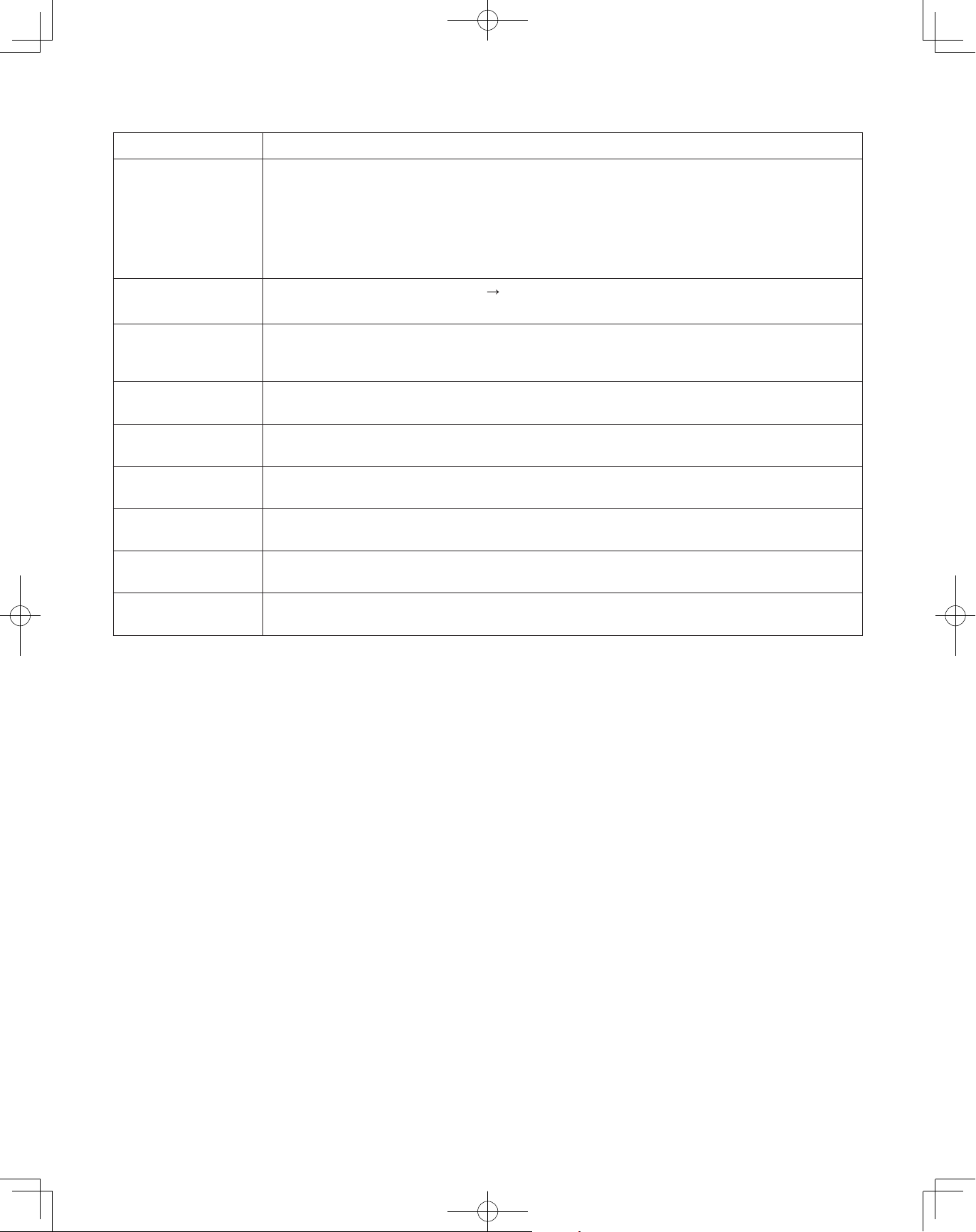
7-4. Function Switches on P.C. Board
Function Switch Remarks
Changes to cooling/heating mode. (outdoor main unit is only usable.)
When in normal operation: When short circuited the COOL side, indoor unit operation in the same
MODE pin (3P, BLK)
(CN40)
When in auto address setting: Changes to heating mode with open-circuit.
refrigerant system changes to all cooling mode.
When short circuited the HEAT side, indoor unit operation in the same
refrigerant system changes to all heating mode.
A.ADD pin (2P, WHT)
(CN30)
CHK pin (2P, WHT)
(CN23)
RC plug (3P, BLU)
(CN73)
RUN pin (2P, WHT)
(CN27)
STOP pin (2P, WHT)
(CN28)
AP pin (2P, WHT)
(CN24)
SNOW plug (3P, RED)
(CN34)
SILENT plug (2P, WHT)
(CN33)
Short circuited for over 1 second long
If short circuit lasts for over 1 second long during auto address setting, the setting is interrupted.
When short circuited, test run begins.
(If the remote controller is connected in test run mode, it is automatically cancelled after 1 hour.)
Also, if short-circuit is cancelled, test run mode is cancelled.
Connects to outdoor unit maintenance remote controller and content of alarm message will be
checked.
When short circuited and pulse signal is given, all indoor units operate in the same refrigerant system.
When short circuited and pulse signal is given, all indoor units stop in the same refrigerant system.
(When short circuited, operation cannot be performed by the indoor unit's remote controller.)
Can be used when vacuuming the outdoor unit.
Can be used when installing a snowfall sensor device.
Can be used when setting the outdoor unit fan in sound absorbing mode.
For details, refer to Test Run Service Manual.
Auto address setting starts with open-circuit.
45
00_302411_EN.indd 45 2018/7/4 13:27:58
Page 46

123
231
1
2
7-5. Auto Address Setting
Example: Basic Wiring Diagram (1)
• Caseofnolinkwiring
(Inter-unit control wiring is not connected to a multiple system.)
Indoor unit address setting is possible without starting the compressor.
Unit 1 setting (outdoor main unit)
System address
(System 1 setting)
(SW1)
(SW2)
ON
1
2
(SW6)
ON
1
ON
OFF
Unit
ON
number
2
setting
3
OFF
(unit 1)
Unit 1
(Main)
1
Number of
outdoor units
(3 units setting)
Outdoor Unit
No. of indoor units
(10 units setting)
(SW3)
0
(SW4)
ON
ON
3
2
1
OFF
(SW5)
ON
ON
213
OFF
Set the terminating
resistance pin
to SHORT side.
(CN67)
Inter-outdoor unit
control wiring
Inter-unit control wiring
* It is not necessary to control the terminating
resistance pin (3P) (CN67) on the outdoor unit
P.C. board.
3P pin is plugged in SHORT side at shipment.
Confirm it is plugged in SHORT side.
Unit 2 setting Unit 3 setting
Unit
number
setting
(unit 2)
(SW5) (SW5)
ON
1
ON
OFF OFF
2
3
Unit 2
(Sub)
Inter-outdoor unit
control wiring
Unit
number
setting
(unit 3)
ON
1
Unit 3
(Sub)
3P terminating
resistance pin
(SHORT side)
OPENSHORT
ON
2
3
Indoor unit
Remote controller
1-1 1-2 1-3 1-10
Remote control
communication wiring
Case 1
Auto Address Control from Outdoor Unit
1. Regarding the number of outdoor units, set the Dip switch (SW6) for setting the number of outdoor units on Unit 1 control P.C.B to 3
ON
units
ON
and the Unit Number Setting Dip switch (SW5) to unit number 1.
OFF
ON
This unit becomes the outdoor main unit.
ON
2. Set the Unit Number Setting switch (SW5) on unit 2 control P.C. board to unit number 2.
3
2
1
ON
Set the Unit Number Setting switch (SW5) on unit 3 control P.C. board to unit number 3.
3
2
1
3. Check the refrigerant system's Address Setting Rotary switch (SW1) on outdoor main unit control P.C. board to “1” and the Dip switch
ON
ON
(SW2) to “0” (at shipment).
OFF
4. Regarding the setting of the number of indoor units connected to the outdoor unit, set the Dip switch (SW4) for setting the number of
ON
ON
indoor units on outdoor main unit control P.C. board connected to the outdoor unit to “1”.
231
OFF
If the Rotary switch (SW3) set to “0”, 10 units can be prepared for operation.
5. Turn on power to indoor and outdoor units.
6. Short circuit the A.ADD pin (CN30) on outdoor main unit control P.C. board for over 1 second long and open circuit.
Communication for auto address setting begins.
* To cancel, short circuit the A.ADD pin (CN30) again for over 1 second long and then open circuit. The LED that
indicates auto address setting goes out and the process is stopped.
Be sure to perform auto address setting again.
Auto address setting is completed when LEDs 1 and 2 on outdoor main unit control P.C. board go out.
7. Remote control operation is now available.
* When auto address setting is controlled by the remote controller, perform auto address setting by the remote controller after step 5
described above.
See to section “Auto Address Setting from Remote Controller”.
●
46
00_302411_EN.indd 46 2018/7/4 13:27:58
Page 47

Example: Basic Wiring Diagram (2)
• Caseoflinkwiring
No. 1 refrigerant system
Unit 1 setting (outdoor main unit)
System address
(System 1 setting)
(SW1) (SW2)
1
Number of
outdoor units
(3 units setting)
Central Controller
Inter-unit
control wiring
ON
ON
2
1
OFF
(SW6)
ON
2
3
1
Outdoor unit
system 1
Indoor unit
ON
OFF
* See the section “ATTENTION!”.
No. of indoor units
(13 units setting)
(SW3)
3
(SW4)
ON
Unit
number
setting
(unit 1)
ON
3
2
1
OFF
(SW5)
ON
213
ON
OFF
Unit
number
setting
(unit 2)
Set the terminating
Unit 1
(Main)
resistance pin to
SHORT side. (CN67)
Inter-outdoor unit
control wiring
Inter-unit control wiring
1-1 1-2 1-131-3
Unit 2 setting
(SW5)
ON
1
2
3
Unit 2
(Sub)
Setting of terminal pin (CN67)
Refrigerant circuit No. 1
Unit No. 1 (Main) : short-circuit (at shipment)
Unit No. 2 (Sub) : short-circuit (at shipment)
Unit No. 3 (Sub) : short-circuit (at shipment)
Refrigerant circuit No. 2 to z-1
Unit No. 1 (Main) : open-circuit
Unit No. 2 (Sub) : short-circuit (at shipment)
Refrigerant circuit No. z
Unit No. 1 (Main) : short-circuit (at shipment)
Unit No. 2 (Sub) : short-circuit (at shipment)
Unit 3 setting
ON
OFF
Unit
number
setting
(unit 3)
(SW5)
ON
3
2
1
Unit 3
(Sub)
Inter-outdoor unit
control wiring
ON
OFF
No. 2 refrigerant system
No. z refrigerant system
Remote
Controller
Unit 1 setting (outdoor main unit)
System address
(System 2 setting)
(SW1) (SW2)
2
ON
ON
2
1
OFF
Number of
outdoor units
(2 units setting)
(SW6)
ON
2
1
ON
3
OFF
Outdoor unit
system 2
Indoor unit
Remote
Controller
Remote control
communication wiring
Number of indoor units
(9 units setting)
(SW3)
9
Unit 1
(Main)
(SW4)
ON
Unit
number
setting
(unit 1)
ON
213
OFF
(SW5)
ON
ON
213
OFF
Set the terminating
resistance pin to
OPEN side. (CN67)
Unit
number
setting
(unit 2)
Unit 2 setting
(SW5)
ON
123
Unit 2
(Sub)
ON
OFF
Inter-outdoor unit control wiring
Inter-unit control wiring
2-1 2-2 2-9
Remote control
communication wiring
Set the terminating
resistance pin to
SHORT side. (CN67)
Unit 2
(Sub)
Inter-unit
Outdoor unit
system z
Unit 1
(Main)
control wiring
Inter-unit control wiring
Inter-outdoor unit control wiring
To z refrigerant system indoor unit
47
00_302411_EN.indd 47 2018/7/4 13:27:58
Page 48

231
3
2
1
3
2
1
123
1
2
● Final check before operation
Final check must be done under the conditions of inter-outdoor unit control wiring
connected to the centralized control system and the resistor between conductors
must be measured by a Megger. Check if it is showing between 30Ω and 120Ω.
If the resistance value is out of range, check adjustment of the termination resistor again.
Even if it is out of range, the problem is caused by wiring.
• Is the wiring connection properly completed?
• Are there any scratches or deterioration on the coverage?
• Measure between conductors and also between wiring and ground by 500V Megger
insulation resistance tester.
Make sure the Megger is showing more than 100MΩ.
When measuring, remove both ends of the wiring from the terminal board.
If not removed, it will be damaged.
If it is less than 100MΩ, a new wiring connection should be made.
Make settings according to each case as described below.
●
• In case of possibility of turning ON power to indoor/outdoor units for each refrigerant system
• In case of impossibility of turning ON power to indoor/outdoor units for each refrigerant system
Auto address setting in heating mode
Auto address setting in cooling mode
Case 2
In case of possibility of turning ON power to indoor/outdoor units for each refrigerant system:
●
In case of possibility of turning ON power to indoor/outdoor units for each refrigerant system:
Indoor unit address setting can be made without starting the compressor.
How to control auto address setting from outdoor unit
1. Set the unit number setting switch (SW5) on unit 1 (outdoor main unit) control P.C. board to:
Between conductors
Wire
Wire
Between wiring and ground
Wire
Wire
Ground Ground
Case 2
Case 3.a
Case 3.b
ON
(Unit 1: This unit becomes to the outdoor main unit.)
ON
Set the unit number setting switch (SW5) on unit 2 control P.C. board to:
ON
Set the unit number setting switch (SW5) on unit 3 control P.C. board to:
2. Regarding the number of outdoor units, set the Dip switch (SW6) for setting the number of outdoor units on outdoor main unit
ON
ON
control P.C. board to 3 units.
OFF
3. Check that the refrigerant system address Rotary switch (SW1) on outdoor main unit control P.C. board in 1 refrigerant system is
ON
ON
set to “1” and the Dip switch (SW2) is set to “0” (at shipment).
OFF
4. Regarding the number of indoor units connected to the outdoor unit, set the Dip switch (SW4) for setting the number on indoor
units on outdoor main unit control P.C. board to “1”
ON
1
ON
and set the Rotary switch (SW3) to “3”.
2
3
OFF
Total of 13 units installation are made.
5. Turn ON power to all indoor and outdoor units in one refrigerant system.
6. Short circuit the A.ADD pin (CN30) of outdoor main unit for over 1 second long and then open circuit.
(Communication for auto address setting begins.)
* To cancel, again short circuit the A.ADD pin (CN30) for over 1 second long and then open circuit.
LEDs 1 and 2 that indicate auto address setting is in progress go out and that process is stopped.
Be sure to perform auto address setting again.
(Auto address setting is completed when the compressor stops and LEDs 1 and 2 on outdoor main unit control P.C. board go out.)
7. Turn ON power to indoor and outdoor units only for another refrigerant system and repeat steps 1 to 5 described above.
Complete auto address setting for each refrigerant system.
8. Remote control operation is now available.
* When performing auto address setting by the remote controller, perform auto address setting by the remote controller after
step 5.
Refer to section “Auto Address Setting by Remote Controller.”
●
48
00_302411_EN.indd 48 2018/7/4 13:27:59
Page 49

Case 3.a
In case of impossibility of turning ON power to indoor/outdoor units in each refrigerant system:
●
(Auto address setting in heating mode)
Indoor unit auto address setting cannot be made unless the compressor is started.
How to control automatic address from outdoor unit
Case 2
1. Make all settings following the same procedure described under steps 1 to 4 in
.
5. Turn ON power to all indoor and outdoor units in all refrigerant systems.
6. If you wish to make auto address setting in
heating mode
, short circuit the A.ADD pin (CN30) on outdoor main unit control
P.C. board for the desired auto address setting in a refrigerant system for over 1 second long and then open circuit.
(Be sure to make settings in each refrigerant system. It is impossible to perform auto address setting in a multiple refrigerant
system simultaneously.)
(Communication for auto address setting begins and the compressor is started and auto address setting in heating mode
begins.)
(All indoor units can also be operated.)
* To cancel, again short circuit the A.ADD pin (CN30) for over 1 second long and then open circuit.
LEDs 1 and 2 that indicate auto address setting is in progress go out and that process is stopped.
Be sure to perform auto address setting again.
(Auto address setting is completed when the compressor stops and LEDs 1 and 2 on outdoor main unit control P.C. board go
out.)
7. Short circuit the A.ADD pin (CN30) on outdoor main unit in another refrigerant system for over 1 second long and then open
circuit.
(Repeat the same procedure and complete auto address setting.)
8. Remote control operation is now available.
* When installing auto address setting by the remote controller, control auto address setting by the remote controller after step 5.
Refer to section “Auto Address Setting by Remote Controller.”
●
49
00_302411_EN.indd 49 2018/7/4 13:27:59
Page 50

Case 3.b
In case of impossibility of turning ON power to indoor/outdoor units in each refrigerant system:
●
(Automatic address setting in cooling mode)
The indoor unit auto address setting cannot be made unless the compressor is started.
How to control automatic address from outdoor unit
Case 2
1. Make all settings following the same procedure described under steps 1 to 4 of
.
5. Turn ON power to all indoor and outdoor units in all refrigerant systems.
6. If you wish to make auto address setting in
cooling mode
, while short circuiting COOL side of the MODE pin (CN40) on
outdoor main unit control P.C. board for the desired auto address setting, short circuit the A.ADD pin (CN30) for over 1 second
long and then open circuit.
(Be sure to install address settings in each refrigerant system. It is impossible to perform auto address setting in a multiple
refrigerant system simultaneously.)
(Communication for auto address setting begins and the compressor starts and auto address setting in cooling mode begins.)
(All indoor units can also be operated.)
* To cancel, again short circuit the A.ADD pin (CN30) for over 1 second long and then open circuit.
LEDs 1 and 2 that indicate auto address setting is in progress go out and that process is stopped.
Be sure to perform auto address setting again.
(Auto address setting is completed when the compressor stops and LEDs 1 and 2 on outdoor main unit control P.C. board go
out.)
7. Short circuit the A.ADD pin (CN30) on outdoor main unit in another refrigerant system for over 1 second long.
Then, open circuit.
(Repeat the same procedure and complete auto address setting.)
8. Remote control operation is now available.
* It is impossible to perform auto address setting in cooling mode by the remote controller.
50
00_302411_EN.indd 50 2018/7/4 13:27:59
Page 51

Auto Address Setting from the High-spec Wired Remote Controller (CZ-RTC5A)
Keep pressing the
1
simultaneously for 4 or more seconds.
,
and
buttons
The “Maintenance func” screen appears on the LCD
display.
Press the
2
or
button to see each menu.
If you wish to see the next screen instantly, press the
or
button.
Select “9. Auto address” on the LCD display and
press the
The “Auto address” screen appears on the LCD
3
9. Auto address
10. Set elec. consumption
11. Set touch key
12. Check touch key
Sel. Page [ ] Confirm
button.
Maintenance func
20:30 (THU)
display.
Change the “Code no.” to “A1” by pressing the
or button.
Auto address
Code no. O/D unit no.
A1
Sel. Next
20:30 (THU)
1
20:30 (THU)
[ ]
START
CZ-RTC5A
Select the “O/D unit no.” by pressing the
4
button.
or
Select one of the “O/D unit no.” for auto address by
pressing the
or
button.
Approximately about 10 minutes are required.
When auto address setting is completed, the units
return to normal stopped status.
Auto Address Setting* from the Remote Controller (CZ-RTC4)
* Auto address setting in Cooling mode cannot be done from the remote controller.
N OT E
Selecting each refrigerant system individually for auto address setting
●
Auto address setting for each system: Item code “A1”
●
Press and hold the remote controller timer time
1
button
and button simultaneously for 4 seconds or longer.
Next, press either the temperature setting
2
/
button.
Check that the item code is “A1”.
Use either the
3
button to set the system No. to perform
auto address setting.
Then press the
4
button.
Auto address setting for one refrigerant system begins.
When auto address setting for one system is completed,
the system returns to normal stopped status.
<Approximately 4 – 5 minutes are required.>
During auto address setting, “
” is displayed on
the remote controller. This message disappears when auto
address setting is completed.
Repeat the same steps to perform auto address setting for
5
2
each successive system.
4
3
1
51
00_302411_EN.indd 51 2018/7/4 13:28:00
4
CZ-RTC4
Page 52

Display During Auto Address Setting
1
2
On the surface of outdoor unit control P.C. board
●
LED
* Do not short circuit the A.ADD pin (CN30) again during auto address setting.
LEDs 1 and 2 go out and address setting is interrupted.
* When auto address setting is normally completed, both LEDs 1 and 2 go out.
Blinks alternately
Contents of LEDs 1 and 2 on outdoor unit control P.C. board
●
In other cases, correct settings referring to the following table and perform auto address setting again.
: Illuminating
: Blinking
: Go out
LED 1 LED 2 Contents of display
After turned ON power (not during auto address setting), it is entirely impossible to communicate with
the indoor unit in the system.
After turned ON power (not during auto address setting), although the indoor units more than 1 unit in
the system are recognized, there are inconsistencies between the number of indoor units and setting
number of indoor units.
Alternately
Under auto address setting
Auto address setting completed
There are inconsistencies between the number of indoor units and setting number of indoor units.
Simultaneously
Alternating
Display of remote controller
●
(at the time of auto address setting)
See the section “7-8. Self-Diagnosis Function Table and Contents of Alarm Display”.
CZ-RTC5A CZ-RTC4
Auto address
1
Assigning
Cancel
Blinking “ ” indicator
Request concerning recording the indoor/outdoor unit combination Nos.
After auto address setting has been completed, be sure to record them for future reference.
List the outdoor main unit system address and the addresses of the indoor units in that system in an easily visible location (next
to the nameplate), using a permanent marking pen or similar means that cannot be abraded easily.
Example: (Outdoor) 1 - (Indoor) 1-1, 1-2, 1-3… (Outdoor) 2 - (Indoor) 2-1, 2-2, 2-3…
These numbers are necessary for later maintenance. Please be sure to indicate them.
52
00_302411_EN.indd 52 2018/7/4 13:28:01
Page 53

Checking the indoor unit addresses
Use the remote controller to check the indoor unit address.
CZ-RTC5A (High-spec wired remote controller)
Keep pressing the
1
simultaneously for 4 or more seconds.
,
and
buttons
The “Maintenance func” screen appears on the LCD
display.
The “Simple settings” screen appears on the LCD
3
display.
Select the “Unit no.” by pressing the
or
button for changes.
Press the
2
Maintenance func
1. Outdoor unit error data
2. Service contact
3. RC setting mode
4.Test run
Sel. Page [ ] Confirm
or
20:30 (THU)
button to see each menu.
If you wish to see the next screen instantly, press the
or
button.
Select “7. Simple settings” on the LCD display and
press the
button.
Maintenance func
5. Sensor info.
6. Servicing check
7. Simple settings
8. Detailed settings
Sel. Page [ ] Confirm
20:30 (THU)
Simple settings
Unit no. Code no. Set data
3-1 0001
Sel. Next
20:30 (THU)
01
The indoor unit fan operates only at the selected
indoor unit.
20:30 (THU)
[ ]
START
CZ-RTC5A
CZ-RTC4 (Timer remote controller)
<If 1 indoor unit is connected to 1 remote controller>
1. Press and hold the
seconds or longer (simple settings mode).
2. The address is displayed for the indoor unit that is connected to
the remote controller.
Only the address of the indoor unit that is connected to the
remote controller can be checked.
3. Press the
controller mode.
<If multiple indoor units are connected to 1 remote controller (group control)>
1. Press and hold the
seconds or longer (simple settings mode).
2. “ALL” is displayed on the remote controller.
3. Next, press the
4. The address is displayed for 1 of the indoor units which is
connected to the remote controller. Check that the fan of that
indoor unit starts and that air is discharged.
5. Press the
each indoor unit in sequence.
6. Press the
mode.
button again to return to normal remote
again to return to normal remote controller
button and button for 4
button and button for 4
button.
button again and check the address of
Number changes to
indicate which indoor unit
is currently selected.
Indoor unit address
Number changes
to indicate which
indoor unit is currently
selected.
Indoor unit address
53
00_302411_EN.indd 53 2018/7/4 13:28:02
Page 54

7-6. Setting Test Run Remote Controller
CZ-RTC5A (High-spec wired remote controller)
Keep pressing the
1
buttons simultaneously for 4 or more seconds.
,
and
The “Maintenance func” screen appears on the
LCD display.
20:30 (THU)
[ ]
START
Maintenance func
1. Outdoor unit error data
2. Service contact
3. RC setting mode
4.Test run
Sel. Page [ ] Confirm
Press the or button to see each menu.
2
20:30 (THU)
If you wish to see the next screen instantly, press
the
or
button.
Select “4. Test run” on the LCD display and press
the
button.
Maintenance func
1. Outdoor unit error data
2. Service contact
3. RC setting mode
4.Test run
Sel. Page [ ] Confirm
20:30 (THU)
Change the display from OFF to ON by pressing
the or button. Then press the
button.
Test run
Test run
20:30 (THU)
ON
CZ-RTC5A
Press the
3
button. “TEST” will be displayed
on the LCD display.
20:30 (THU)
TEST
START[ ]
Press the
4
button. Test run will be started.
Test run setting mode screen appears on the LCD
display.
20:30 (THU)
TEST
MODE
COOL
Change
CZ-RTC4 (Timer remote controller)
1. Press the remote controller
Then press the
“
●
●
2. The test run can be performed using the HEAT, COOL, or FAN
3. If correct operation is not possible, a code is displayed on the remote
4. After the test run is completed, press the
” appears on the LCD display while the test run is in progress.
The temperature cannot be adjusted when in Test Run mode.
This mode places a heavy load on the machines.
Therefore, use it only when performing the test run.
operation modes.
N OT E
The outdoor units will not operate for approximately 3 minutes after the
power is turned ON and after operation is stopped.
controller LCD display.
See the section “7-8. Self-Diagnosis Function Table and Contents of
Alarm Display” and correct the problem.
Check that “
To prevent continuous test runs, this remote controller includes a timer
function that cancels the test run after 60 minutes.
* If the test run is performed using the wired remote controller, operation
is possible even if the cassette-type ceiling panel has not been
installed. (“P09” display does not occur.)
[ ] Confirm
button for 4 seconds or longer.
button.
button again.
” disappears from the LCD display.
1
1
4
CZ-RTC4
54
00_302411_EN.indd 54 2018/7/4 13:28:03
Page 55

7-7. Caution for Pump Down
CAUTION
Pump down means refrigerant gas in the system is returned to the outdoor unit.
Pump down is used when the unit is to be moved, or before servicing the refrigerant circuit.
Refer to Service Manual.
This outdoor unit cannot collect more than the rated refrigerant amount as shown by the
CAUTION
●
nameplate on the back.
If the amount of refrigerant is more than that recommended, do not conduct pump down.
●
In this case use another refrigerant collecting system.
7-8. Self-Diagnosis Function Table and Contents of Alarm Display
How to know LEDs 1 and 2 alarm display on outdoor unit control P.C. board
LED 1 LED 2 Contents of Alarm Display
Alarm display
Alternating
After LED1 blinks M times, LED2 blinks N times.
This will be repeated.
Times of blinks Type of alarm
2 P Alarm
3 H Alarm
M
4 E Alarm
5 F Alarm
6 L Alarm
N = Times of alarm No.
For example: After LED1 blinks twice, LED2 blinks 17 times. This will be repeated.
The alarm shows “P17”.
: Blink) Connect the outdoor unit maintenance remote controller to the RC plug (3P, BLU) on outdoor main unit control
(
P.C. board and make confirmation.
Self-Diagnosis Function Table
n
• Cause and countermeasure against the symptom of auto address failure
Symptom Cause and countermeasure
• When turning ON power to the outdoor main unit, LEDs 1
and 2 illuminate or blink excluding going out.
Auto address setting is not available.
• When auto address setting by the remote controller begins,
the alarm display appears immediately.
• When auto address setting by the remote controller begins,
no display appears.
• Auto address setting begins but finishes improperly.
Symptom Cause and countermeasure
• Soon after a few seconds or after a few minutes, the alarm
content is displayed on the remote controller.
See “Contents of Alarm Display” and make corrections.
Are remote control wiring and inter-unit control wiring
connected properly?
Is indoor unit turned ON power?
See “Contents of Alarm Display” and make a correction.
• After a few minutes when auto address setting begins, the
compressor may occasionally start and stop several times.
LEDs 1 and 2 on outdoor unit control P.C. board show the
display of auto address setting with blinking alternately
but LEDs 1 and 2 do not indicate the completion of auto
address setting (go out).
00_302411_EN.indd 55 2018/7/4 13:28:03
Are remote control wiring and inter-unit control wiring
connected properly?
Is indoor unit turned ON power?
55
Page 56

• If the alarm display “E15”, “E16” and “E20” appear after auto address setting began, check the following items.
Alarm display Alarm contents
E15
E16
E20
Have you forgotten to turn ON power to indoor unit?
Are indoor and outdoor control wiring connected properly?
(Check for incorrect wiring to open & short-circuit, terminal pin and remote control terminal.)
Is remote control wiring connected properly? (Check for open & short-circuit, wrong connection
to indoor/outdoor unit control wiring terminal, inter-unit control wiring.)
Are the number of the connecting indoor units set by SW3 and SW4 of outdoor main unit control
P.C. board connected properly?
Is additional appropriate amount of refrigerant charge?
(Compressor ON at the time of auto address setting)
Is the refrigerant tubing connected properly?
(Compressor ON at the time of auto address setting)
Are E1 and E3 sensors of indoor unit normal?
(Compressor ON at the time of auto address setting)
Are there any wrong system address installed in indoor units caused by manual or incorrect auto
address control?
1) When auto address setting from outdoor main unit control P.C. board or remote controller begins, “Under Setting” appears on the
remote controller as for normal indoor units under the inter-unit control wirings and remote control wirings.
LEDs 1 and 2 indicators on outdoor main unit control P.C. board blink alternately.
2) If there is an error at the inter-unit control wiring of the remote controller when in the indoor unit group control, address setting
may not occasionally be made although “under setting” is displayed.
3) Although the alarm “E15” and “E16” are displayed, addresses will be installed in the recognized indoor units.
The installed addresses can be checked by the remote controller. See the section “Checking the indoor unit address”.
• When operating the remote controller after auto address setting completed (LEDs 1 and 2 indicators on outdoor main unit control
P.C. board go out), correct the symptom if the following alarms appear on the remote controller.
Remote control display
No display
If any other alarm appear on the display, refer to the Test Run Service Manual.
Recognized number of indoor units at the time of auto address setting are fewer than that of indoor units
set by SW3 and SW4 on outdoor main unit P.C. board.
Recognized number of indoor units at the time of auto address setting are more than that of indoor units
set by SW3 and SW4 on outdoor main unit P.C. board.
Outdoor unit could not entirely receive serial communication signal from the indoor unit within 90
seconds after auto address setting began.
Check E15 E16 E20
Cause
Remote controller is not connected properly. (Power failure)
When auto address setting was completed, the power of indoor unit was turned off.
Indoor unit does not respond to remote controller.
E01
E02
P09 Connection to the panel of indoor unit is not good.
Indoor unit address was mistakenly controlled by undesired indoor unit remote controller.
(Impossible to communicate with outdoor unit)
The remote controller is having error in sending serial communication signal.
(Impossible to communicate with indoor unit by remote controller)
• Alarm display can be checked by the outdoor maintenance remote controller. When operating, refer to the Test Run Service
Manual.
Alarm display can also be checked by number of blinking of LEDs 1 and 2 on outdoor unit control P.C. board.
See the section “How to know LEDs 1 and 2 alarm display on outdoor unit control P.C. board” under the section “7-8. SelfDiagnosis Function Table and Contents of Alarm Display”.
Remote control display Alarm contents
E01 Indoor unit does not respond to remote controller.
E02 The remote controller is having error in sending serial communication signal.
E03 Controller does not respond to indoor unit.
E04 Oudoor unit does not respond to indoor unit.
E06 Some indoor units does not respond to outdoor unit.
E08 Indoor unit address is dupulicating.
56
00_302411_EN.indd 56 2018/7/4 13:28:03
Page 57

Remote control display Alarm contents
E09 Two or more remote controllers are set as main on R1-R2 link.
E12 Auto Address failed to start.
E14 Two or more indoor units are set as main, in the group controlled indoor units.
E15 Fewer indoor units are found in Auto Addressing than the setting on outdoor PCB.
E16 More indoor units are found in Auto Addressing than the setting on outdoor PCB.
E18 No response from sub indoor to the main indoor unit in group control wiring.
E20 No indoor unit responded in Auto Addressing.
E24 No response from sub outdoor unit.
E25 The outdoor unit address is duplicating.
E26 The number of responding outdoor units does not match with the setting on the main outdoor unit.
E27 Improper wiring between main and sub outdoor units.
E29 No response from main outdoor unit.
E30
The outdoor unit is having error in sending serial communication signal on main-sub communication line.
E31 Error in communication inside outdoor unit control box.
F01 E1 thermistor on liquid side of indoor heat exchanger has failure. (E1)
F02 Indoor unit set as single split. (E2)
F03 E3 thermistor on gas side of indoor heat exchanger has failure. (E3)
F04 DISCH1 thermistor at the discharge of 1st compressor reading is abnormal.
F05 DISCH2 thermistor at the discharge of 2nd compressor reading is abnormal.
F06 EXG1 thermistor at the gas side of 1st heat exchanger of the outdoor unit has failure. (EXG1)
F07 EXL1 thermistor at the liquid side of 1st heat exchanger of the outdoor unit has failure. (EXL1)
F08 TO thermistor for outdoor ambient air temperature has failure. (TO)
F10 TA thermistor for intake air temperature (room temperature) of the indoor unit has failure. (TA)
F11 BL thermistor for supply air temperature of the indoor unit has failure. (BL)
F12 SCT thermistor at the suction refrigerant of compressors has failure. (SCT)
F14 SCG thermistor at the outlet of subcooling heat exchanger in outdoor unit has failure. (SCG)
F16 High pressure sensor of the outdoor unit has failure. (HPS)
F17 Low pressure sensor of the outdoor unit has failure. (LPS)
F23 EXG2 thermistor at the gas side of 2nd heat exchanger of the outdoor unit has failure. (EXG2)
F24 EXL2 thermistor at the liquid side of 2nd heat exchanger of the outdoor unit has failure. (EXL2)
F29 EEPROM on indoor unit PCB has failure.
F31 EEPROM on outdoor unit PCB has failure.
H01 Overcurrent in 1st compressor.
H03 Current sensor for the 1st compressor is disconnected or shorted.
H05
DISCH1 thermistor at the discharge of 1st compressor is disconnected, shorted or misplaced. (DISCH1)
H06 Low pressure is too low.
H07 Low on oil or the oil recovery circuit has restriction.
H08 OIL1 thermistor for the oil of 1st compressor has failure. (OIL1)
H11 Overcurrent in 2nd compressor.
H13 Current sensor for the 2nd compressor is disconnected or shorted.
H15
DISCH2 thermistor at the discharge of 2nd compressor is disconnected, shorted or misplaced. (DISCH2)
H21 HIC for 2nd compressor has failure. Overcurrent or overheat of HIC.
H27 OIL2 thermistor for the oil of 2nd compressor has failure. (OIL2)
H31 HIC for 1st compressor has failure. Overcurrent or overheat of HIC.
L01 Indoor unit address setting has error. (No main indoor unit in group control.)
L02 Indoor unit model does not match with the outdoor unit model. (Multi-split/mini-split)
L03 Two or more indoor units are set as main in group control.
L04 Duplicate system address setting on outdoor units.
L05 Two or more indoor units are set as priority indoor unit.
L06 Two or more indoor units are set as priority indoor unit.
L07 Group control wiring is detected for indoor unit set as individual control.
L08 Indoor unit address is not set.
L09 Capacity setting of indoor unit is not correct.
L10 Capacity setting of outdoor unit is not correct.
L13 Indoor unit model does not match with outdoor unit.
L17 Model mismatch between outdoor units in one refrigerant circuit.
L18 Reversing valve or solenoid valve failure.
P01 Indoor fan motor activated thermal protector.
P03 1st compressor discharge temperature too high.
57
00_302411_EN.indd 57 2018/7/4 13:28:03
Page 58

Remote control display Alarm contents
P04
Protection device activated. High pressure switch (63PH, 63PH1 or 63PH2) or compressor thermal
protector (49C1 / 49C2).
P05 Missing phase in power input is detected at HIC for 1st compressor.
P09 Connection to the panel of indoor unit is not good.
P10 Float switch of drain pan safety is activated.
P11 Drain pump failure or locked rotor.
P12 Indoor fan inverter protection control is activated.
P14 Input detected at EXCT terminal on indoor PCB for refrigerant detector.
P15 Missing phase in power input is detected at HIC for 2nd compressor.
P16
Overcurrent of 1st compressor on the secondary side of inverter circuit, or inverter failed to syncronize
with rotation.
P17 2nd compressor discharge temperature too high.
P19 Inverter for 2nd compressor failed to start or failed to syncronize with rotation.
P20 Too high load in refrigerant circuit.
P22 Fan motor or inverter drive of outdoor unit has failure.
P26
Overcurrent of 2nd compressor on the secondary side of inverter circuit, or inverter failed to syncronize
with rotation.
P29 Inverter for 1st compressor failed to start or failed to syncronize with rotation.
P31 Other indoor unit in group control has an alarm.
• Contents of alarm display on remote controller
For the remote controller, there are other alarm contents listed on the following table besides the alarm display on outdoor main
unit control P.C. board.
Wired remote
control display
<E01>
<E02>
<<E03>>
E04
E06
E08
<<E09>>
E12
E15
E16
E20
E24
E25
E26
E29
E31
<<L02>>
<L03>
L05
L06
L07
L08
<<L09>>
L04
L10
L17
L18
Remote controller is detecting error signal
from indoor unit.
Controller does not respond to indoor unit.
Indoor unit is detecting error signal from
main outdoor unit.
Outdoor unit is detecting error signal from
indoor unit.
Improper setting of indoor unit or remote
controller.
During auto address setting, number of
connected units does not correspond to
number set.
When turning on the power supply, number
of connected units does not correspond to
number set.
(Except R.C. address is “0.”)
Improper setting.
Detected contents
Indoor unit does not respond to remote controller.
The remote controller is having error in sending serial
communication signal.
Outdoor unit does not respond to indoor unit.
Some indoor units does not respond to outdoor unit.
Indoor unit address is dupulicating.
Two or more remote controllers are set as main on R1-R2 link.
Auto Address failed to start.
Fewer indoor units are found in Auto Addressing than the setting
on outdoor PCB.
More indoor units are found in Auto Addressing than the setting
on outdoor PCB.
No indoor unit responded in Auto Addressing.
No response from sub outdoor unit.
The outdoor unit address is duplicating.
The number of responding outdoor units does not match with
the setting on the main outdoor unit.
No response from main outdoor unit.
Error in communication inside outdoor unit control box.
Indoor unit model does not match with the outdoor unit model.
(Multi-split/mini-split)
Two or more indoor units are set as main in group control.
Two or more indoor units are set as priority indoor unit.
Two or more indoor units are set as priority indoor unit.
Group control wiring is detected for indoor unit set as individual
control.
Indoor unit address is not set.
Capacity setting of indoor unit is not correct.
Duplicate system address setting on outdoor units.
Capacity setting of outdoor unit is not correct.
Model mismatch between outdoor units in one refrigerant circuit.
Reversing valve or solenoid valve failure.
58
00_302411_EN.indd 58 2018/7/4 13:28:03
Page 59

Wired remote
control display
<<F01>>
<<F02>>
<<F03>>
<<F10>>
<<F11>>
F04
F05
F06
F07
F08
F12
F14
F16
F17
F23
F24
<<P01>>
<<P09>>
<<P10>>
<<P12>>
P14
P03
P04
P05
P15
P16
P17
P19
P20
P22
P26
P29
<P31>
F29
F31
H01
H03
H05
H11
H13
H15
H06
H08
H27
Indoor thermistor is either open or damaged.
Outdoor thermistor is either open or damaged.
Protective device in indoor unit is activated.
Protective device in outdoor unit is activated.
Indoor unit communication error of group control
wiring.
EEPROM on indoor unit PCB failure
EEPROM on outdoor unit PCB failure
Protective device for compressor No. 1 is
activated.
Protective device for compressor No. 2 is
activated.
Oil sensor fault. (Disconnection, etc.)
Detected contents
E1 thermistor on liquid side of indoor heat exchanger has failure. (E1)
Indoor unit set as single split. (E2)
E3 thermistor on gas side of indoor heat exchanger has failure. (E3)
TA thermistor for intake air temperature (room temperature) of the indoor
unit has failure. (TA)
BL thermistor for supply air temperature of the indoor unit has failure.
(BL)
DISCH1 thermistor at the discharge of 1st compressor reading is
abnormal.
DISCH2 thermistor at the discharge of 2nd compressor reading is
abnormal.
EXG1 thermistor at the gas side of 1st heat exchanger of the outdoor
unit has failure. (EXG1)
EXL1 thermistor at the liquid side of 1st heat exchanger of the outdoor
unit has failure. (EXL1)
TO thermistor for outdoor ambient air temperature has failure. (TO)
SCT thermistor at the suction refrigerant of compressors has failure.
(SCT)
SCG thermistor at the outlet of subcooling heat exchanger in outdoor
unit has failure. (SCG)
High pressure sensor of the outdoor unit has failure. (HPS)
Low pressure sensor of the outdoor unit has failure. (LPS)
EXG2 thermistor at the gas side of 2nd heat exchanger of the outdoor
unit has failure. (EXG2)
EXL2 thermistor at the liquid side of 2nd heat exchanger of the outdoor
unit has failure. (EXL2)
Indoor fan motor activated thermal protector.
Connection to the panel of indoor unit is not good.
Float switch of drain pan safety is activated.
Indoor fan inverter protection control is activated.
Input detected at EXCT terminal on indoor PCB for refrigerant detector.
1st compressor discharge temperature too high.
Protection device activated. High pressure switch (63PH, 63PH1 or
63PH2) or compressor thermal protector (49C1 / 49C2).
Missing phase in power input is detected at HIC for 1st compressor.
Missing phase in power input is detected at HIC for 2nd compressor.
Overcurrent of 1st compressor on the secondary side of inverter circuit,
or inverter failed to syncronize with rotation.
2nd compressor discharge temperature too high.
Inverter for 2nd compressor failed to start or failed to syncronize with
rotation.
Too high load in refrigerant circuit.
Fan motor or inverter drive of outdoor unit has failure.
Overcurrent of 2nd compressor on the secondary side of inverter circuit,
or inverter failed to syncronize with rotation.
Inverter for 1st compressor failed to start or failed to syncronize with
rotation.
Other indoor unit in group control has an alarm.
Overcurrent in 1st compressor.
Current sensor for the 1st compressor is disconnected or shorted.
DISCH1 thermistor at the discharge of 1st compressor is disconnected,
shorted or misplaced. (DISCH1)
Overcurrent in 2nd compressor.
Current sensor for the 2nd compressor is disconnected or shorted.
DISCH2 thermistor at the discharge of 2nd compressor is disconnected,
shorted or misplaced. (DISCH2)
Low pressure is too low.
OIL1 thermistor for the oil of 1st compressor has failure. (OIL1)
OIL2 thermistor for the oil of 2nd compressor has failure. (OIL2)
59
00_302411_EN.indd 59 2018/7/4 13:28:03
Page 60

Wired remote
control display
H21
H31
Abnormal device function
Detected contents
HIC for 2nd compressor has failure. Overcurrent or overheat of HIC.
HIC for 1st compressor has failure. Overcurrent or overheat of HIC.
• The parentheses of << >> used in the table of alarm display does not affect anything the operation of other indoor units.
• The parentheses of < > used in the table of alarm display implies that there are two cases: according to the content of the
symptom, some affect the operation of other indoor units and others do not affect anything.
Alarm messages displayed on system controller
Indoor or main outdoor unit is not operating correctly.
Mis-wiring of control wiring between indoor unit, main outdoor unit and
system controller.
Indoor or main outdoor unit is not operating correctly.
Mis-wiring of control wiring between indoor unit, main outdoor unit and
system controller.
CN1 is not connected properly.
When using wireless remote controller or system controller, in order to
check the alarm message in detail, connect wired remote controller to
indoor unit temporarily.
C05
C06
P30
Serial
communication
errors
Mis-setting
Activation of
protective
device
Error in transmitting serial
communication signal
Error in receiving serial
communication signal
Protective device of sub indoor
unit in group control is activated.
NOTE
1. Alarm messages in << >> do not affect other indoor unit operations.
2. Alarm messages in < > sometimes affect other indoor unit operations depending on the fault.
ATTENTION!
Adjustment of terminating resistance (pin) is necessary.
Communication failure will occur unless adjustment is made correctly.
• Terminating resistance (pin) is mounted on outdoor unit control P.C. board.
• When connecting central controller, interface or peripheral equipment, adjustment of terminating resistance (pin) is necessary.
Although the connection is not made, confirmation is necessary for VRF systems.
• In the case of a refrigerant system, the terminating resistance (pin) for this inter-unit control wiring (S-LINK wiring) is one
location (See the section “7-5. Auto Address Setting”).
For 2 or more refrigerant systems, 2 locations should be valid (“SHORT” for VRF systems at shipment). See the section
“7-5. Auto Address Setting”.
In order to make 2 locations valid, let the terminating resistance (pin) of the nearest outdoor unit and the farthest outdoor unit be
valid (SHORT side) from the location of central controller.
In other refrigerant systems excepting 2 locations described above, make them invalid (OPEN side).
It is prohibited making more than 3 locations of terminating resistance valid.
• Since the use of linking the sub outdoor units of VRF systems is not connected to the inter-unit control wiring, it is not necessary
to make the terminating resistance invalid “OPEN side”.
Make final confirmation regarding the central controller or interface & inter-unit control wiring (S-LINK wiring) connected to the
peripheral equipment.
Measure the line resistance with a tester and check whether the values are in the range of 30Ω - 120Ω.
If the resistance values are out of range, check again the terminating resistance.
Nevertheless, if the values are out of range, the problem comes from wiring.
• Is the connection properly made?
• Are there any scratches or damages on the coated surface?
Megger
Line
(Wire)
(Wire)
• Measure the line, between wires and ground with the 500V megger (insulation
resistance meter) and check the values are over 100MΩ.
• When measuring, be sure to remove both edges of the wire from the terminal board.
If not removed, it will be damaged.
• If the line resistance is within 100MΩ, newly carry out the wiring work.
Between wires and ground
(Wire)
(Wire)
(Ground)
60
00_302411_EN.indd 60 2018/7/4 13:28:03
Page 61

– NOTE –
61
00_302411_EN.indd 61 2018/7/4 13:28:03
Page 62

– NOTE –
62
00_302411_EN.indd 62 2018/7/4 13:28:03
Page 63

– NOTE –
63
00_302411_EN.indd 63 2018/7/4 13:28:03
Page 64

Printed in China
85464369760022
00_302411_EN.indd 64 2018/7/4 13:28:04
ACXF60-18511
DC0314-30718
 Loading...