

Page 1
Operating Instructions
Air Conditioner
Before operating the unit, read these operating instructions thoroughly and
keep them for future reference.
Model No.
Indoor Units
CASSETTE
(4-WAY: U1 type)
S-22MU1E5
S-28MU1E5
S-36MU1E5
S-45MU1E5
S-56MU1E5
S-73MU1E5
S-106MU1E5
S-140MU1E5
S-160MU1E5
(4-WAY: Y1 Type)
S-22MY1E5
S-28MY1E5
S-36MY1E5
S-45MY1E5
S-56MY1E5
(1-WAY: D1 Type)
S-28MD1E5
S-36MD1E5
S-45MD1E5
S-56MD1E5
S-73MD1E5
(2-WAY: L1 Type)
S-22ML1E5
S-28ML1E5
S-36ML1E5
S-45ML1E5
S-56ML1E5
S-73ML1E5
CEILING-MOUNTED
(T1 Type)
S-36MT1E5
S-45MT1E5
S-56MT1E5
S-73MT1E5
S-106MT1E5
S-140MT1E5
FLOOR STANDING
(P1 Type)
S-22MP1E5
S-28MP1E5
S-36MP1E5
S-45MP1E5
S-56MP1E5
S-71MP1E5
WALL-MOUNTED
(K1 Type)
S-22MK1E5
S-28MK1E5
S-36MK1E5
S-45MK1E5
S-56MK1E5
S-73MK1E5
S-106MK1E5
CONCEALED
FLOOR STANDING
(R1 Type)
S-22MR1E5
S-28MR1E5
S-36MR1E5
S-45MR1E5
S-56MR1E5
S-71MR1E5
CONCEALED DUCT
(Slim Low Static)
(M1 Type)
S-22MM1E5
S-28MM1E5
S-36MM1E5
S-45MM1E5
S-56MM1E5
(Low Silhouette)
(F1 Type)
S-22MF1E5
S-28MF1E5
S-36MF1E5
S-45MF1E5
S-56MF1E5
S-73MF1E5
S-90MF1E5
S-106MF1E5
S-140MF1E5
S-160MF1E5
Outdoor Units
Mini VRF U-4LE1E5, U-5LE1E5, U-6LE1E5
U-4LE1E8, U-5LE1E8, U-6LE1E8
This air conditioner uses the refrigerant R410A.
85464609141021
(High Static Pressure)
(E1 Type)
S-73ME1E5
S-106ME1E5
S-140ME1E5
S-224ME1E5
S-280ME1E5
Panasonic Corporation
1006 Kadoma, Kadoma City, Osaka, Japan
Page 2
Contents
Product Information .......................................................................................................................2
Alert Symbols ................................................................................................................................2
Installation Location.......................................................................................................................3
Electrical Requirements ................................................................................................................3
Safety Instructions.........................................................................................................................4
Wireless Remote Controller (Optional parts) ................................................................................5
NOTE Refer to the Operating Instructions attached to the optional Wireless Remote
Controller. ....................................................................................................................5
Timer Remote Controller (Optional parts) .....................................................................................5
NOTE Refer to the Operating Instructions attached to the optional Timer Remote
Controller. ....................................................................................................................5
Operation Condition ......................................................................................................................5
Adjusting the Airflow Direction.......................................................................................................6
Adjusting the Airflow Direction for Multiple Indoor Units Using a Single Remote Controller
(Wired)...........................................................................................................................................8
Special Remarks ...........................................................................................................................9
Care and Cleaning ........................................................................................................................9
Specifications ............................................................................................................................112
Page
Product Information
If you have problems or questions concerning your Air Conditioner, you will need the following
information. Model and serial numbers are on the nameplate on the bottom of the cabinet.
Model No. _________________________________ Serial No. _______________________
Date of purchase______________________________________________________________
Dealer’s address ______________________________________________________________
Phone number________________________________________________________________
Alert Symbols
The following symbols used in this manual, alert you to potentially dangerous conditions
to users, service personnel or the appliance:
This symbol refers to a hazard or unsafe practice
which can result in severe personal injury or
death.
This symbol refers to a hazard or unsafe practice
which can result in personal injury or product or
property damage.
2
OI-141-2-EN
Page 3
Installation Location
• We recommend that this air conditioner be installed properly by qualified installation
technicians in accordance with the Installation Instructions provided with the unit.
• Before installation, check that the voltage of the electric supply in your home or office is the
same as the voltage shown on the nameplate.
• Do not install this air conditioner where there are fumes or flammable gases, or in an
extremely humid space such as a greenhouse.
• Do not install the air conditioner where excessively high heat-generating objects
are placed.
Avoid: To protect the air conditioner from heavy corrosion, avoid installing the outdoor unit where
salty sea water can splash directly onto it or in sulphurous air near a spa.
Electrical Requirements
1. All wiring must conform to the local electrical codes. Consult your dealer or a qualified
electrician for details.
2. Each unit must be properly grounded with a ground (or earth) wire or through the supply
wiring.
3. Wiring must be done by a qualified electrician.
The wires in this mains lead are colored in accordance with the following code:
Green-and-Yellow: Earth
Blue: Neutral
Brown: Live
As the colors of the wires in the mains lead of this appliance may not correspond with the colored
markings identifying the terminals in your plugs, proceed as follows:
The wire which is colored green and yellow must be connected to the terminal in the plug which
is marked by the letter E or by the safety earth symbol or colored green or green-and-yellow.
The wire which is colored blue must be connected to the terminal which is marked with letter N or
colored black.
The wire which is colored brown must be connected to the terminal which is marked with the
letter L or colored red.
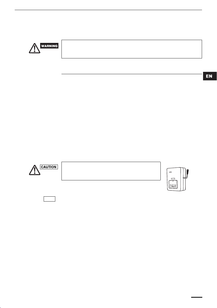
To warm up the system, the power mains must be turned on
at least five (5) hours before operation. Leave the power
mains ON unless you will not be using this appliance for an
extended period.
Power mains
ON
OI-141-3-EN
NOTE
Pull off the power plug from a receptacle, or switch off the breaker, or switch off the power
disconnecting mean to isolate the air conditioner from the main power supply when not in use
for a long time.
3
Page 4
NOTICE
Safety Instructions
• Read these Operating Instructions carefully before using this air conditioner. If you still
have any difficulties or problems, consult your dealer for help.
• This air conditioner is designed to give you comfortable room conditions. Use this only
for its intended purpose as described in these Operating Instructions.
• Confirm to authorized dealer or specialist on usage of specified refrigerant type.
Using of refrigerant other than the specified type may cause product damage, burst
and injury etc.
• Never touch the unit with wet hands.
• Never use or store gasoline or other flammable vapor or liquid near the air
conditioner — it is very dangerous.
• Do not use this appliance in a potentially explosive atmosphere.
• This air conditioner has no ventilator for intaking fresh air from outdoors. You must
open doors or windows frequently when you use gas or oil heating appliances in
the same room, which consume a lot of oxygen from the air. Otherwise there is a
risk of suffocation in an extreme case.
• Provide a power outlet to be used exclusively for each unit, and a power supply
disconnect, circuit breaker and earth leakage breaker for overcurrent protection
should be provided in the exclusive line.
• Provide a power outlet exclusively for each unit, and full disconnection means
having a contact separation in all poles must be incorporated in the fixed wiring in
accordance with the wiring rules.
• To prevent possible hazards from insulation failure, the unit must be
grounded.
• Do not clean inside the indoor and outdoor units by users. Engage authorized
dealer or specialist for cleaning.
• In case of malfunction of this appliance, do not repair by yourself. Contact to the
sales dealer or service dealer for a repair.
• Refrigerant gas leakage may cause fire.
• For safety, be sure to turn the air conditioner off and also to disconnect
the power before cleaning or servicing.
• Pull off the power plug from a receptacle, or switch off the breaker, or
switch off the power disconnecting mean to isolate the air conditioner from the
main power supply in case of emergency.
• Do not turn the air conditioner on and off from the power mains switch. Use the ON/
OFF operation button.
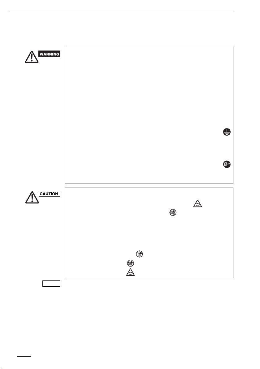
• Do not stick anything into the air outlet of the outdoor unit.
This is dangerous because the fan is rotating at high speed.
• Do not touch the air inlet or the sharp aluminum
fins of the outdoor unit. You may get injured.
• Keep the fire alarm and the air outlet at least 1.5m away from the unit.
• This appliance is not intended for use by persons(including children) with reduced
physical, sensory or mental capabilities, or lack of experience and knowledge,
unless they have been given supervision or instruction concerning use of the
appliance by a person responsible for their safety. Children should be supervised to
ensure that do not play with the appliance.
• Do not cool or heat the room too much if babies or invalids are present.
• Do not sit or step on the unit.
You may fall down accidentally.
• Do not stick any object
into the FAN CASE.
You may be injured and
the unit may be damaged.
• The compressor may occasionally stop during thunderstorms.
This is not a mechanical failure. The unit automatically recovers after a few minutes.
• The English text is the original instructions. Other languages are translation of the
original instructions.
4
OI-141-4-EN
Page 5
Wireless Remote Controller (Optional parts)
NOTE
NOTE
Refer to the Operating Instructions attached to the optional Wireless Remote Controller.
Timer Remote Controller (Optional parts)
Refer to the Operating Instructions attached to the optional Timer Remote Controller.
Operation Condition
Use this air conditioner under the following temperature range.
Indoor temperature range:
Cooling mode 14°C ~ 25°C (*WBT) / 18°C ~ 32°C (*DBT)
Heating mode 16°C ~ 30°C (*DBT)
Outdoor temperature range:
Cooling mode -10°C ~ 46°C (*DBT)
Heating mode -20°C ~ 18°C (*WBT) / -20°C ~ 24°C (*DBT)
*DBT: Dry bulb temperature
*WBT: Wet bulb temperature
OI-141-5-EN
5
Page 6
Adjusting the Airflow Direction
The functions differ depending on the indoor unit used. The airflow direction cannot be set
using the remote controller for any unit which is not listed below.
U1 type, Y1 type, L1 type, D1 type, T1 type and K1 type.
• Never use your hands to move the flap (vertical airflow flap) that is controlled using the
remote controller.
• When the air conditioner is turned off, the flap (vertical airflow flap) automatically moves to
the downward position.
• The flap (vertical airflow flap) moves to the upward position when performing the standby
operation for heating. The swing operation is made after the standby operation for heating is
released, but swing is indicated on the remote controller even during the standby operation
for heating.
Setting the airflow
direction
To activate the swing
operation
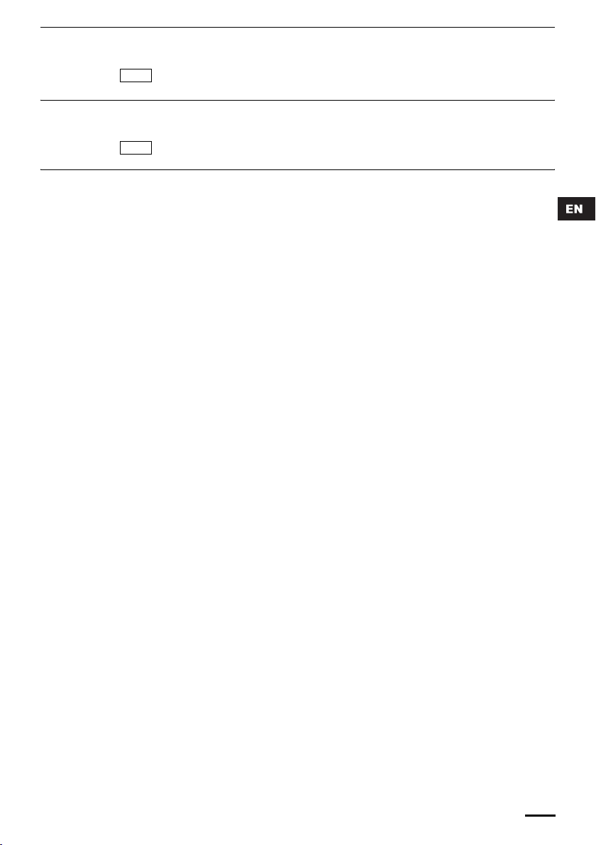
Heating Cooling and drying Fan operation All operations
Set the flap (vertical airflow flap) to the downward
position. If the flap is set to the upward position,
the warm air may not reach the floor.
The airflow direction changes each time the FLAP button is pressed during operation.
Press the FLAP button to set the flap (vertical airflow flap) to the downward position, and then
press the FLAP button again. This displays , and the airflow automatically swings up and
down.
The flap (vertical airflow flap) can
be set to one of three positions.
Initial setting
Initial setting
Initial setting
Continuous
operation
To stop the swing
operation
6
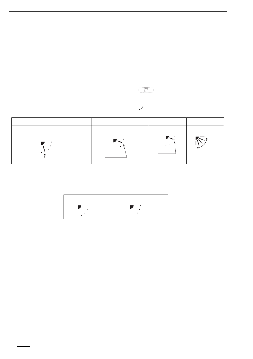
Press the FLAP button again during the flap swing operation to stop the flap at the desired
position. Then, the airflow can be set from the top position by pressing the FLAP button again.
Indicator when swing operation is stopped
Fan and heating Cooling and drying
During cooling or drying operation, the flap will not stop at the downward position. Even if the
flap is stopped at the downward position during the swing operation, it will not stop until it
moves to the third position from the top.
OI-141-6-EN
Page 7

Adjusting the Airflow Direction (continued)
U1 type, Y1 type, L1 type and D1 type air conditioners are equipped with auto flaps.
You can set the airflow direction to a specific angle or to the sweep mode using the remote
controller.
Do not move the flap with your hands.
4-way (U1 type), (Y1 type) • The air outlet flap can be easily removed and washed with water.
Indoor unit
• Be sure to always stop operation before removing the flap.
• After washing with water, allow it to dry, and then remount it with the arrow facing outward.
Ceiling mounted type (T1)
Vertical directions (automatic)
This air conditioner is equipped with an auto flap. You can set the airflow direction to a specific
angle or to the sweep mode using the remote controller. (Refer to the description of the remote
controller.)
Do not move the flap with your hands.
Horizontal directions (manual)
The horizontal airflow direction can be adjusted manually by moving the vertical vanes to the
left or right.
Wall mounted type (K1)
Vertical directions (automatic)
Confirm that the remote controller has been turned on. Press the FLAP button to start the flap
moving up and down. If you want to stop the flap movement and to direct the air in the desired
direction, press the FLAP button again. In the cool mode, do not direct the flap down and move
out of the cooling zone “A”, otherwise, condensation may drip on to the floor. Zone ‘‘A’’ is the
recommended flap position for cooling.
When operating continuously in the fixed airflow direction setting for about an hour, the airflow
direction is automatically controlled and the flap position is changed. The airflow direction may
be different from the display on the remote controller.
Do not move the flap with your hands.
Zone
‘‘A’’ for
cooling
OI-141-7-EN
Zone ‘‘B’’ for
heating
Horizontal directions (manual)
The horizontal airflow direction can be adjusted manually by moving the vertical vanes to the
left or right.
Concealed duct type (F1, M1, E1)
This air conditioner is not equipped with air outlet parts. These must be obtained locally. Please
refer to the manual of the locally adopted air outlet parts.
7
Page 8

Adjusting the Airflow Direction for Multiple Indoor Units
Using a Single Remote Controller (Wired)
• The airflow direction cannot be set using the remote controller for the concealed duct type
(F1, M1, E1) and floor standing type (P1, R1).
• If multiple indoor units are connected to a remote controller, the airflow direction can be set
for each indoor unit by selecting the indoor units (see the operation below).
Auto Flap ( ) button
One outdoor unit and eight indoor units Two outdoor units and four indoor units
No display
Unit No.
1–1
• To set the airflow for individual units, press the UNIT button. Display shows the indoor unit
number under group control. Set the airflow direction for the indoor unit that is shown on the
display.
• Each time UNIT is pressed, the indicator changes in the order shown below.
• When nothing is displayed, you can make the setting for all indoor units in one operation.
• The unit number is displayed as Outdoor Unit Number–Indoor Unit Number. It varies
depending on the number of units under group control.
Unit
Unit
Unit
Unit No.
1–2
Unit No.
1–3
Unit No.
1–8
No
display
Unit
No.
1–1
No.
1–2
No.
1–3
No.
1–4
Unit
No.
2–1
Unit
No.
2–4
8
OI-141-8-EN
Page 9

Special Remarks
‘‘DRY’’ Operation
How it works • Once the room temperature reaches the level that was set, the unit repeats the cycle of
Heating Operation
Heating performance • Because this appliance heats a room by utilizing the heat of the outside air (heat pump
Defrosting • When the outdoor temperature is low, frost or ice may form on the outdoor heat exchanger
(standby) on the
display
NOTE
turning on and off automatically.
• In order to prevent the humidity in the room from rising again, the indoor fan also turns off
when the unit stops operating.
• The fan speed is set to ‘‘LO.’’ automatically, and cannot be adjusted.
• ‘‘DRY’’ operation is not possible if the outdoor temperature is 15 °C or less.
system), the heating efficiency will fall off when the outdoor temperature is very low. If
sufficient heat cannot be obtained with this heat pump, use another heating appliance in
conjunction with this unit.
coil, reducing the heating performance. When this happens, a microcomputer-controlled
defrosting system operates. At the same time, the fan on the indoor unit stops (or runs at
very low speed in some cases) and the ‘‘STANDBY’’ indicator appears on the display until
defrosting is completed. Heating operation then restarts after several minutes. (This interval
will vary slightly depending upon the outdoor temperature and the way in which frost forms.)
• For several minutes after the start of heating operation, the indoor fan will not start running
(or it will run at very low speed in some cases) until the indoor heat exchanger coil has
warmed up sufficiently. This is because a cold draft prevention system is operating. During
this period, the ‘‘ ’’ (standby) indicator remains displayed.
• ‘‘ ’’ (standby) remains displayed during defrosting or when the compressor has been
turned off (or when the unit is running at very low speed) by the thermostat when the
system is in the heating mode.
• Upon completion of defrosting and when the compressor is turned on again, ‘‘ ’’
(standby) will turn off automatically as heating operation resumes.
Should the power fail while the unit is running
If the power supply for this unit is temporarily cut off, the unit will automatically resume
operation (once the power is restored) using the same settings before the power was cut off.
Air intake and outlet side
OI-141-9-EN
(Indoor unit)
Care and Cleaning
1. For safety, be sure to turn the air conditioner off and also to disconnect the power
before cleaning.
2. Do not pour water on the indoor unit to clean it. This will damage the internal
components and cause an electric shock hazard.
Clean the air intake and outlet side of the indoor unit with a vacuum cleaner brush, or wipe
them with a clean, soft cloth.
If these parts are stained, use a clean cloth moistened with water. When cleaning the air outlet
side, be careful not to force the vanes out of place.
1. Never use solvents or harsh chemicals when cleaning the indoor unit. Do not wipe
plastic parts using very hot water.
2. Some metal edges and the fins are sharp and may cause injury if handled
improperly; be especially careful when you clean these parts.
3. The internal coil and other components of the outdoor unit must be cleaned
periodically. Consult your dealer or service center.
9
Page 10

Information for Users on Collection and Disposal of Old Equipment and Used Batteries
These symbols on the products, packaging, and/or accompanying documents mean that used electrical and
electronic products and batteries should not be mixed with general household waste.
For proper treatment, recovery and recycling of old products and used batteries, please take them to
applicable collection points, in accordance with your national legislation and the Directives 2002/96/EC and
2006/66/EC.
By disposing of these products and batteries correctly, you will help to save valuable resources and prevent
any potential negative effects on human health and the environment which could otherwise arise from
inappropriate waste handling.
For more information about collection and recycling of old products and batteries, please contact your local
municipality, your waste disposal service or the point of sale where you purchased the items.
Penalties may be applicable for incorrect disposal of this waste, in accordance with national legislation.
For business users in the European Union
If you wish to discard electrical and electronic equipment, please contact your dealer or supplier for further
information.
[Information on Disposal in other Countries outside the European Union]
These symbols are only valid in the European Union. If you wish to discard these items, please contact your
local authorities or dealer and ask for the correct method of disposal.
Note for the battery symbol (bottom two symbol examples):
This symbol might be used in combination with a chemical symbol. In this case it complies with the requirement
Pb
set by the Directive for the chemical involved.
Safety Instructions
Stop using the product when any abnormality/failure occurs and
disconnect the power plug.
(Risk of smoke/fire/electric shock)
Examples of
abnormality/
failure
- The product sometimes does not start when turned on.
- The power is sometimes disconnected when the cord is moved.
- Burnt odor or abnormal noise is detected during operation.
- The body is deformed or abnormally hot.
Contact immediately your local dealer for maintenance/repair.
To be followed absolutely
10
OI-141-10-EN
Page 11

Specifications
4-Way Cassette (U1 type)
Model Name
Power Source 220 - 230 - 240 V, single-phase, 50/60 Hz
Cooling Capacity
Heating Capacity
High
Sound Pressure Level
Sound Power Level
Unit Dimensions (H×W×D)
Net Weight
Model Name S-106MU1E5 S-140MU1E5
Power Source 220 - 230 - 240 V, single-phase, 50/60 Hz
Cooling Capacity
Heating Capacity
Sound Pressure Level
Sound Power Level
Unit Dimensions (H×W×D)
Net Weight
Medium
Low
High
Medium
Low
High
Medium
Low
High
Medium
Low
S-22MU1E5 S-28MU1E5 S-36MU1E5 S-45MU1E5 S-56MU1E5 S-73MU1E5
kW
BTU/h
kW
BTU/h
dB(A)
dB(A)
dB(A)
dB(A)
dB(A)
dB(A)
mm
kg
kW
BTU/h
kW
BTU/h
dB(A)
dB(A)
dB(A)
dB(A)
dB(A)
dB(A)
mm
kg 29 29
2.2 2.8 3.6 4.5
7,500 9,600 12,000 15,000
2.5 3.2 4.2 5.0
8,500 11,000 14,000 17,000
29 29 29 30
28 28 28 28
27 27 27 27
44 44 44 47
42 42 42 45
41 41 41 43
290×950×950
10.6 14.0
36,000 47,800
11.4 16.0
39,000 54,600
353×950×950
290×950×950 290×950×950 290×950×950 290×950×950 290×950×950
24
43 44
38 39
32 33
60 61
55 55
47 49
24
353×950×950
24
S-160MU1E5
16.0
54,600
18.0
61,400
45
40
34
62
56
50
353×950×950
29
19,000
21,000
24 24 25
5.6
6.3
7.3
25,000
8.0
27,000
32
29
27
50
47
44
35
31
28
54
48
44
Ceiling (T1 type)
Model Name
Power Source 220 - 230 - 240 V, single-phase, 50/60 Hz
Cooling Capacity
Heating Capacity
High
Sound Pressure Level
Sound Power Level
Unit Dimensions (H×W×D)
Net Weight
Medium
Low
High
Medium
Low
S-36MT1E5 S-45MT1E5 S-56MT1E5 S-73MT1E5 S-106MT1E5 S-140MT1E5
kW
BTU/h
kW
BTU/h
dB(A)
dB(A)
dB(A)
dB(A)
dB(A)
dB(A)
mm
kg
3.6 4.5 5.6 7.3
12,000 15,000 19,000 25,000
4.2 5.0 6.3 8.0
14,000 17,000 21,000 27,000
35 36 36 38
32 33 33 36
30 30 30 33
46 47 47 49
43 44 44 47
41 41 41 44
210×910×680
210×910×680 210×910×680 210×1180×680 210×1595×680 210×1595×680
21
21 21 25 33 33
36,000
39,000
112
10.6
11.4
41
38
35
52
49
46
14.0
47,800
16.0
54,600
43
40
37
54
51
48
Page 12

Specifications
High Static Pressure Ducted (E1 type)
Model Name
Power Source 220 - 230 - 240 V, single-phase, 50/60 Hz
Cooling Capacity
Heating Capacity
High
Sound Pressure Level
Sound Power Level
Unit Dimensions (H×W×D)
Net Weight
Medium
Low
High
Medium
Low
4-Way Cassette 60x60 (Y1 type)
Model Name S-22MY1E5 S-28MY1E5 S-36MY1E5 S-45MY1E5 S-56MY1E5
Power Source 220 - 230 - 240 V, single-phase, 50/60 Hz
Cooling Capacity
Heating Capacity
High
Sound Pressure Level
Sound Power Level
Unit Dimensions (H×W×D)
Net Weight
Medium
Low
High
Medium
Low
Slim Low Static Ducted (M1 type)
Model Name
Power Source 220 - 230 - 240 V, single-phase, 50/60 Hz
Cooling Capacity
Heating Capacity
High
Sound Pressure Level
Sound Power Level
Unit Dimensions (H×W×D)
Net Weight
Medium
Low
High
Medium
Low
S-73ME1E5 S-106ME1E5 S-140ME1E5 S-224ME1E5 S-280ME1E5
220 - 230 - 240 V,
single-phase, 50 Hz
kW
BTU/h
kW
BTU/h
dB(A)
dB(A)
dB(A)
dB(A)
dB(A)
dB(A)
mm
kg 47 50 54 110 120
kW
BTU/h
kW
BTU/h
dB(A)
dB(A)
dB(A)
dB(A)
dB(A)
dB(A)
mm
kg
kW
BTU/h
kW
BTU/h
dB(A)
dB(A)
dB(A)
dB(A)
dB(A)
dB(A)
mm
kg
7.3 10.6 14.0 22.4
25,000 36,000 47,800 76,400
8.0 11.4 16.0 25.0
27,000 39,000 54,600 85,300
44 45 47 48
43 44 46 47
42 42 44 46
55 56 58 59
54 55 57 58
53 53 55 57
420×1065×620
7,500 9,600 12,000 16,000
8,500 11,000 14,000 17,000
313×625×625
S-22MM1E5 S-28MM1E5 S-36MM1E5 S-45MM1E5 S-56MM1E5
7,500 9,600 12,000 15,000
8,500 11,000 14,000 17,000
200×750×640
420×1065×620 450×1065×620
2.2 2.8 3.6 4.7
2.5 3.2 4.2 5.0
30 30 32 36
27 27 29 32
25 25 26 28
46 46 49 53
43 43 46 48
41 41 42 45
313×625×625 313×625×625 313×625×625 313×625×625
18.4
2.2 2.8 3.6 4.5
2.5 3.2 4.2 5.0
28 30 32 34
27 29 30 32
25 27 28 30
43 45 47 49
42 44 45 47
40 42 43 45
19
18.4 18.4 18.4 18.4
200×750×640 200×750×640 200×750×640 200×750×640
19 19 19 19
467×1428×1230 467×1428×1230
28.0
95,500
31.5
107,500
51
50
49
62
61
60
5.6
19,000
6.3
21,000
41
37
33
58
54
50
5.6
19,000
6.3
21,000
35
33
31
52
50
48
113
Page 13

Specifications
Low Silhouette Ducted (F1 type)
Model Name
Power Source 220 - 230 - 240 V, single-phase, 50/60 Hz
Cooling Capacity
Heating Capacity
High
Sound Pressure Level
Sound Power Level
Unit Dimensions (H×W×D)
Net Weight
Model Name S-90MF1E5 S-106MF1E5
Power Source 220 - 230 - 240 V, single-phase, 50/60 Hz
Cooling Capacity
Heating Capacity
Sound Pressure Level
Sound Power Level
Unit Dimensions (H×W×D)
Net Weight
Medium
Low
High
Medium
Low
High
Medium
Low
High
Medium
Low
S-22MF1E5 S-28MF1E5 S-36MF1E5 S-45MF1E5 S-56MF1E5 S-73MF1E5
kW
BTU/h
kW
BTU/h
dB(A)
dB(A)
dB(A)
dB(A)
dB(A)
dB(A)
mm
kg
kW
BTU/h
kW
BTU/h
dB(A)
dB(A)
dB(A)
dB(A)
dB(A)
dB(A)
mm
kg 32 47 47
2.2 2.8 3.6 4.5
7,500 9,600 12,000 15,000
2.5 3.2 4.2 5.0
8,500 11,000 14,000 17,000
29 29 29 30
26 26 26 28
22 22 22 25
40 40 40 41
37 37 37 39
33 33 33 36
310×700×630
30,000 36,000
10.0 11.4
34,000 39,000
310×1000×630
310×700×630 310×700×630 310×700×630 310×700×630 310×1000×630
24
9.0 10.6
34 38
30 33
27 31
45 49
41 44
38 42
24 24 25 25 32
310×1480×630
S-140MF1E5
47,800
54,600
310×1480×630
S-160MF1E5
14.0
16.0
40
37
33
51
48
44
310×1480×630
16.0
54,600
18.0
61,500
40
37
33
51
48
44
47
5.6
19,000
6.3
21,000
30
28
25
41
39
36
7.3
25,000
8.0
27,000
34
30
27
45
41
38
2-Way Cassette (L1 type)
Model Name
Power Source 220 - 230 - 240 V, single-phase, 50/60 Hz
Cooling Capacity
Heating Capacity
High
Sound Pressure Level
Sound Power Level
Unit Dimensions (H×W×D)
Net Weight
Medium
Low
High
Medium
Low
S-22ML1E5 S-28ML1E5 S-36ML1E5 S-45ML1E5 S-56ML1E5 S-73ML1E5
kW
BTU/h
kW
BTU/h
dB(A)
dB(A)
dB(A)
dB(A)
dB(A)
dB(A)
mm
kg
2.2 2.8 3.6 4.5
7,500 9,600 12,000 15,000
2.5 3.2 4.2 5.0
8,500 11,000 14,000 17,000
30 33 34 35
27 29 31 33
24 26 28 29
40 44 45 46
38 40 42 44
35 37 39 40
358×1060×680
358×1060×680 358×1060×680 358×1060×680 358×1060×680 358×1060×680
30
30 30 30 30 30
114
5.6
19,000
6.3
21,000
35
33
29
46
44
40
7.3
25,000
8.0
27,000
38
35
33
49
46
44
Page 14

Specifications
1-Way Cassette (D1 type)
Model Name
Power Source
Cooling Capacity
Heating Capacity
High
Sound Pressure Level
Sound Power Level
Unit Dimensions (H×W×D)
Net Weight
Medium
Low
High
Medium
Low
Floor Standing (P1 type)
Model Name S-22MP1E5 S-28MP1E5 S-36MP1E5 S-45MP1E5 S-56MP1E5
Power Source 220 - 230 - 240 V, single-phase, 50/60 Hz
Cooling Capacity
Heating Capacity
High
Sound Pressure Level
Sound Power Level
Unit Dimensions (H×W×D)
Net Weight
Medium
Low
High
Medium
Low
S-28MD1E5 S-36MD1E5 S-45MD1E5 S-56MD1E5 S-73MD1E5
220 - 230 - 240 V, single-phase, 50/60 Hz
kW
BTU/h
kW
BTU/h
dB(A)
dB(A)
dB(A)
dB(A)
dB(A)
dB(A)
mm
kg 26.5 26.5 26.5 26.5 27.5
kW
BTU/h
kW
BTU/h
dB(A)
dB(A)
dB(A)
dB(A)
dB(A)
dB(A)
mm
kg
2.8 3.6 4.5 5.6
9,600 12,000 15,000 19,000
3.2 4.2 5.0 6.3
11,000 14,000 17,000 21,000
36 36 36 38
34 34 35 36
33 33 34 34
47 47 47 49
45 45 46 47
44 44 45 45
220×1230×800
7,500 9,600 12,000 15,000
8,500 11,000 14,000 17,000
615×1065×230
220×1230×800 220×1230×800 220×1230×800 220×1230×800
2.2 2.8 3.6 4.5
2.5 3.2 4.2 5.0
33 33 39 38
30 30 35 35
28 28 29 31
44 44 50 49
41 41 46 46
39 39 40 42
615×1065×230 615×1065×230 615×1380×230 615×1380×230
29
29 29 39 39
7.3
25,000
8.0
27,000
45
40
36
56
51
47
5.6
19,000
6.3
21,000
39
36
31
50
47
42
S-71MP1E5
7.1
24,000
8.0
27,000
41
38
35
52
49
46
615×1380×230
39
Concealed Floor Standing (R1 type)
Model Name S-22MR1E5 S-28MR1E5 S-36MR1E5 S-45MR1E5 S-56MR1E5
Power Source 220 - 230 - 240 V, single-phase, 50/60 Hz
Cooling Capacity
Heating Capacity
High
Sound Pressure Level
Sound Power Level
Unit Dimensions (H×W×D)
Net Weight
Medium
Low
High
Medium
Low
kW
BTU/h
kW
BTU/h
dB(A)
dB(A)
dB(A)
dB(A)
dB(A)
dB(A)
mm
kg
2.2 2.8 3.6 4.5
7,500 9,600 12,000 15,000
2.5 3.2 4.2 5.0
8,500 11,000 14,000 17,000
33 33 39 38
30 30 35 35
28 28 29 31
44 44 50 49
41 41 46 46
39 39 40 42
616×904×229
616×904×229 616×904×229 616×1219×229616×1219×229 616×1219×229
21
21 21 28 28
5.6
19,000
6.3
21,000
39
36
31
49
46
42
S-71MR1E5
7.1
24,000
8.0
27,000
41
38
35
52
49
46
616×1219×229
28
115
Page 15

Specifications
Wall Mounted (K1 type)
Model Name
Power Source 220 - 230 - 240 V, single-phase, 50/60 Hz
Cooling Capacity
Heating Capacity
High
Sound Pressure Level
Sound Power Level
Unit Dimensions (H×W×D)
Net Weight
Model Name S-45MK1E5 S-56MK1E5
Power Source 220 - 230 - 240 V, single-phase, 50/60 Hz
Cooling Capacity
Heating Capacity
Sound Pressure Level
Sound Power Level
Unit Dimensions (H×W×D)
Net Weight
Medium
Low
High
Medium
Low
High
Medium
Low
High
Medium
Low
S-22MK1E5 S-28MK1E5 S-36MK1E5
kW
BTU/h
kW
BTU/h
dB(A)
dB(A)
dB(A)
dB(A)
dB(A)
dB(A)
mm
kg
kW
BTU/h
kW
BTU/h
dB(A)
dB(A)
dB(A)
dB(A)
dB(A)
dB(A)
mm
kg 13 13 14.5
2.2 2.8 3.6
7,500 9,600 12,000
2.5 3.2 4.2
8,500 11,000 14,000
35 35 37
32 32 33
28 28 29
46 46 48
43 43 44
39 39 40
285×825×217
15,000 19,000
17,000 21,000
300×1065×230
285×825×217 285×825×217
10
4.5 5.6
5.0 6.3
38 40
34 36
30 32
49 51
45 47
41 43
10 10
300×1065×230
S-73MK1E5
300×1065×230
S-106MK1E5
7.3
25,000
8.0
27,000
47
44
40
58
55
51
300×1065×230
10.6
36,000
11.4
39,000
49
45
42
60
56
53
14.5
116
Page 16

Specifications
Mini VRF (Single-phase)
Model Name
Power Source
Cooling Capacity
Heating Capacity
Sound Pressure Level (C/H)
Sound Power Level (C/H) dB(A)
Unit Dimensions (H×W×D)
Net Weight
Mini VRF (3-phase)
Model Name
Power Source
Cooling Capacity
Heating Capacity
Sound Pressure Level (C/H)
Sound Power Level (C/H) dB(A)
Unit Dimensions (H×W×D)
Net Weight
kW
BTU/h
kW
BTU/h
dB(A)
mm
kg
kW
BTU/h
kW
BTU/h
dB(A)
mm
kg
U-4LE1E5 U-5LE1E5 U-6LE1E5
Single-phase, 220 - 230 - 240 V, 50 Hz
12.1 14.0 15.5
41,300 47,800 52,900
12.5 16.0 18.0
42,700 54,600 61,400
50/52 51/53 52/55
68/70 69/71 70/73
1330×940×340
104
U-4LE1E8 U-5LE1E8 U-6LE1E8
3-phase, 380 - 400 - 415 V, 50 Hz
12.1 14.0 15.5
41,300 47,800 52,900
12.5 16.0 18.0
42,700 54,600 61,400
50/52 51/53 52/55
68/70 69/71 70/73
104
104 104
1330×940×340
104 104
117
Page 17

Specifications
Caractéristiques / Especificaciones / Technische Daten /
Specifiche / Specificatie / Especificações
English Français Español Deutsch
4-Way Cassette (U1 type) Cassette 4 voies (Type U1) Cassette de 4 vías (tipo U1) 4-Weg Kassette (Typ U1)
Ceiling (T1 type) Plafond (Type T1) Techo (tipo T1) Deckenmontage (Typ T1)
High Static Pressure Ducted (E1
type)
4-Way Cassette 60x60 (Y1 type) Cassette 4 voies 60x60 (Type Y1) Cassette de 4 vías 60x60 (tipo Y1) 4-Weg Kassette 60 x 60 (Typ Y1)
Slim Low Static Ducted (M1 type) Conduit Mince Faible S
Low Silhouette Ducted (F1 type) Conduit Silhouette Basse
2-Way Cassette (L1 type) Cassette 2 voies (Type L1) Cassette d e 2 vías (tipo L1) 2-Weg Kassette (Typ L1)
assette (D1 type) Cassette 1 voie (Type D1) Cassette de 1 vía (tipo D1) 1-Weg Kassette (Typ D1)
1-Way C
Floor Standing (P1 type) Vertical au sol (Type P1) De pie (tipo P1) Bodenaufstellung (Typ P1)
Concealed Floor Standing
(R1 type)
Wall Mounted (K1 type) Monté au mur (Type K1) Montado en pared (tipo K1) Wandmontage (Typ K1)
Standard-COP mode Mode COP standard Modo COP estándar COP-Modus Standard
High-COP mode Mode COP élevé Modo COP alto COP-Modus hoch
series) Mini (sér ie LE2) Mini (serie LE2) Mini (Serie LE2)
Mini (LE2
Conduit Haute Pression Statique
(Type E1)
(Type M1)
(Type F1)
Ver ti cal au sol caché (Type R1) De pie y oculto (tipo R1) Bodenaufstellung/Einbau (Typ R1)
tatique
Conductos de presión estática
alta (tipo E1)
Conductos finos de presión
estática baja (tipo M1)
Conductos de silueta baja
(tipo F1)
Kanalgerät mit hoher statischer
Pressung (Typ E1)
Flaches Kanalgerät mit niedriger
statischer Pressung (M1)
Kanalgerät, flache Bauform (Typ
F1)
English Italiano Nederlands Português
4-Way Cassette (U1 type) A cassetta a 4 vie (tipo U1) 4-weg cassette (type U1) Cassete de 4 vias (Tipo U1)
Ceiling (T1 type) A soffitto (tipo T1) Plafond (type T1) Tecto (Tipo T1)
High Static Pressure Ducted
(E1 type)
4-Way Cassette 60x60 (Y1 type) A cassetta a 4 vie 60x60 (tipo Y1) 4-weg cassette 60x60 (type Y1) Cassete de 4 vias 60x60 (Tipo Y1)
Slim Low Static Ducted (M1 type) S
Low Silhouette Ducted (F1 type) A prof ilo basso a condotto
2-Way Cassette (L1 type) A cassetta a 2 vie (tipo L1) 2-weg cassette (type L1) Cassete de 2 vias (Tipo L1)
1-Way Cassette (D1 type) A cassetta
Floor Standing (P1 type) A pavimento (tipo P1) Vloermodel (type P1) Montagem no chão (Tipo P1)
Concealed Floor Standing
(R1 type)
Wall Mounted (K1 type) Con montaggio a parete (tipo K1) Wandmodel (K1) Montagem na parede (Tipo K1)
Standard-COP mode Modalità CO P standard Standaard-COP-modus Modo COP padrão
High-COP mode Modalità COP alta Hoge-COP-modus Modo COP alto
Mini (LE2 series) Mini (s
A condotto ad alta pressione
statica (tipo E1)
ottile a condotto a bassa
pressione statica (tipo M1)
(tipo F1)
a 1 via (tipo D1) 1-weg cassette (type D1) Cassete de 1 via (Tipo D1)
A pavimento nascosto (tipo R1) Verborgen vloermodel (type R1) Montagem no chão oculta
erie LE2) Mini (serie LE2) Mini (Série LE2)
Kanaalmodel met hoge statische
druk (type E1)
Slank laag statisch kanaalmodel
(type M1)
Kanaalmodel met onopvallend
silhouet (type F1)
Pressão estática elevada no tubo
(Tipo E1)
Estática baixa fina no tubo
(Tipo M1)
Baixo perfil no tubo (Tipo F1)
(Tipo R1)
118
Page 18

Specifications
Caractéristiques / Especificaciones / Technische Daten /
Specifiche / Specificatie / Especificações
EnglishFrançais Español Deutsch
Model Name Nom du modèle Nombre del modelo Modellbezeichnung
Power Source Source d'alimentation Fuente de alimentación Spannungsquelle
Cooling Capacity Capacité de refroidissement Capacidad de refrigeración Kühlleistung
Heating Capacity Capacité de chauffage Capacidad de calefacción Heizleistung
Sound Pressure Level (High/
Medium/Low)
Sound Power Level (High/
Medium/Low)
Unit Dimensions (HxWxD; mm) Dimensions d'unité (HxLxP ; mm) Dimensiones de la unidad (Alto x
Mini (LE2 series) Mini (série LE2) Mini (serie LE2) Mini (Serie LE 2)
(HxWxD: ceiling dimension) (HxLxP : dimensions plafond) (Alto x Largo x Ancho: dimensión
Net Weight (kg) Poids net (kg) Peso neto (kg) Nettog ewicht (kg)
Outdoor unit model name ended
with letters “E8E” is salt-air
damage resistant specifications.
Niveau de press
Moyen/Bas)
Niveau de puissance sonore
(Haut/Moyen/Bas)
Les noms de modèle d'unité
extér ieure se terminant par les
lettres « E8E » sont des
spécific
dommages provoqués par l'air
marin.
ion sonore (Haut/
ations de résistance aux
Nivel de presión acústica (alto/
medio/bajo)
Nivel de potencia acústic a (alto/
medio/bajo)
Largo x Ancho; mm)
del techo)
El nombre del modelo de la
unidad exterior termina con los
caracteres “E8E” para indicar sus
especificaciones de resistencia al
aire salado.
Schalldruckpegel (hoch/mittel/
niedrig)
Schallleistungspegel (hoch/mittel/
niedrig)
bmessungen (H x B x T
Gerätea
[mm])
(H x B x T: Deckenmaß)
Die Außeneinheit, deren
Modelbezeichnung auf „E8E“
endet, ist laut Spezifikation
salzluftbeständig.
English Italiano Nederlands Português
Model Name Modello Modelnaam Nome do modelo
Power Source Fonte di alimentazione Voeding Fonte de alimentação
Cooling Capacity Capacità di raffreddamento Koelingscapaciteit Capacidade de arrefecimento
Heating Capacity Capacità di riscaldamento Verwarmingscapaciteit Capacidade de aquecimento
Sound Pressure Level (High/
Medium/Low)
Sound Power Level (High/
Medium/Low)
Unit Dimensions (HxWxD; mm) Dimensioni unit à (AxLxP; mm) Afmetingen van de unit (H x B x D;
Mini (LE2 series) Mini (s
(HxWxD: ceiling dimension) (AxLxP: dimensione soffitto) (H x B x D: plafo ndafmeting) (AxLxP: dimensão do tecto)
Net Weight (kg) Peso netto (kg) Nettogewicht (kg) Peso líquido (kg)
Outdoor unit model name ended
with letters “E8E” is salt-air
damage resistant specifications.
Livello di pressione acustica (alto/
asso)
medio/b
Livello di potenza acustica (alto/
medio/basso)
erie LE2) Mini (serie LE2) Mini (Série LE2)
I nomi dei modelli di unità esterne
che terminano con i caratteri
“E8E” indicano caratteristiche
tecniche di resistenza al
danneggiamento da sal
sedine.
Geluidsdrukniveau (hoog/
normaal/laag)
Geluidsvermogenniveau (hoog/
normaal/laag)
mm)
Als de modelnaam van de
buitenunit eindigt op "E8E",
voldoet het model aan de
specificaties voor producten die
resistent zijn tegen schade door
zoute lucht.
Nível da pressão do som (Alto/
Médio/Baixo)
Nível da potência de som (Alto/
Médio/Baixo)
Dimensões da unidade (AxLxP;
mm)
O nome do modelo da unidade
exterior terminado pelas letras
“E8E” é a especificação de
resistência aos danos do ar
salgado.
119
Page 19

Specifications
Προδιαγραφές / Спецификации /
Технические характеристики / Специфікаціа
English Ελληνικη Български Русский Українська
4-Way Cassette (U1 type) Κασέτας 4-δρομο (Τύπ ος
Ceiling (T1 type) Ορ οφής (Τύ πο ς T1) Таванен (тип Т1) Потолочный (Тип T1) Стельовий (тип T1)
High Static Pressure
Ducted (E1 type)
4-Way Cassette 60x60
(Y1 type)
Slim Low Static Ducted
(M1 type)
Low Silhouette Ducted
(F1 type)
2-Way Cassette (L1 type) Κασέτας 2-δρομο (Τύπ ο ς
1-Way Cassette (D1 type) Κασέτας 1-δρομο (Τύπ ος
Floor Standing (P1 type) Όρθιο δαπέδου (Τύπ ος
Concealed Floor Standing
(R1 type)
Wall Mounted (K1 type) Επιτοίχιο (Τύ π ος K1)
Standard-COP mode Λειτουργία τυπικού COP Режим със стандартен
High-COP mode Λειτουργία υψηλού COP Режим с висок COP
Mini (LE2 series) Mini (Σειρά LE2) Mini (серия LE2) Mini (серии LE2) Mini (серія LE2)
U1)
Αγωγός υψηλής στατικής
πίεσης (Τύπο ς E1)
Κασέτας 4-δρομο 60x60
(Τύπ ο ς Y1)
Αγωγός χαμηλής στατικής
πίεσης λεπτού τύπου
(Τύπ ο ς M1)
Χαμηλής σιλουέτας με
αγωγό (Τύπ ο ς F1 )
L1)
D1)
P1)
Εντοιχισμένο όρθιο
δαπέδου (Τύπ ος R1)
4-пътен касетен (тип U1) Кассетный с 4
Високонапорен канален
(тип Е1)
4-пътен касетен 60х60
(тип Y1)
Тънък нисконапорен
канален (тип М1)
Канален с нисък силует
(тип F1)
2-пътен касетен (тип L1) Кассетный с 2
1-пътен касетен (тип D1) Кассетный с 1
Подов колонен (тип P1) Напольный (Тип P1) Підлоговий (тип P1)
Скрит подов колонен
(тип R1)
Стенен (тип К1) Настенный (тип K1) Настінний (тип K1)
COP (КПД)
(КПД)
направлениями потока
(тип U1)
Скрытый с высоким
статическим давлением
(тип E1)
Кассетный с 4
направлениями потока
60x60 (тип Y1)
Скрытый тонкий с
низким статическим
давлением (тип M1)
Скрытый плоский (тип
F1)
направлениями потока
(тип L1)
направлением потока
(тип D1)
Скрытый напольный (Тип
R1)
Стандартный COP
режим
Высокий COP режим Режим високого ККД
4-канальний касетний
(тип U1)
Із каналом під високим
статичним тиском (тип
E1)
4-канальний касетний
60x60 (тип Y1)
Тонкий, із каналом під
низьким статичним
тиском (тип M1)
Із каналом з низького
профілю (тип F1)
2-канальний касетний
(тип L1)
1-канальний касетний
(тип D1)
Прихований підлоговий
(тип R1)
Режим стандартного ККД
English Ελληνικη Български Русский Українська
Model Name Όνομα μοντέλου Наименование на модел Название модели Назва моделі
Powe r Source Πηγή ισχύος Захранване Источник питания Джерело живлення
Cooling Capacity Δυνατότητα ψύξης Охлаждаща мощност Мощность охлаждения Охолоджувальна
Heating Capacity Δυνατότητα θέρμανση ς Отоплителна мощност Мощность обогрева Нагрівальна здатність
Sound Pressure Level
(High/Medium/Low)
Sound Power Level (High/
Medium/Low)
Unit Dimensions (HxWxD;
mm)
Mini (LE2 series) Mini (Σειρά LE2) Mini (серия LE2) Mini (серии LE2) Mini (серія LE2)
(HxWxD: ceiling
dimension)
Net Weight (kg) Καθαρό βάρος (kg) Нетно тегло (кг) Вес нетто (кг) Вага нетто (кг)
Outdoor unit model name
ended with letters “E8E” is
salt-air damage resistant
specifications.
Επίπεδο πίεσης ήχου
(Υψηλό/Μεσαίο/Χαμηλό)
Επίπεδο ισχύος ήχου
(Υψηλό/Μεσαίο/Χαμηλό)
μονάδας
Διαστάσεις
(ΥxΠxΒ, mm)
(ΥxΠxΒ: διαστάσεις
οροφής)
Το μοντέ λο εξωτερικής
μονάδας του οποίου η
ονομασία τελειώνει
χαρακ τήρες “E8E” είναι
ανθεκτικό στην πρόκληση
βλάβης από αέρα που
περιέχει αλάτι.
με τους
Ниво на звуково
налягане
Ниво на сила на звука Уровень звуковой
Размери на модула
(ВхШхД, мм)
ВхШхД: размери на
тавана)
Външните тела с
наименования на
модела, завършващи на
„E8E”, са устойчиви на
вредните въздействия
на солен въздух.
Уровень звукового
давления (Высокий/
Средний/Низкий)
мощности (Высокий/
Средний/Низкий)
Размеры аппарата
(ВxШxГ; мм)
(ВxШxГ: размеры
потолка)
Название модели
внешнего блока,
оканчивающееся
буквами “E8E”,
представляет собой
устойчивый к соленому
воздуху вариант.
120
здатність
Рівень звукового тиску
(високий/середній/
низький)
Рівень потужності звуку
(високий/середній/
низький)
Розміри пристрою
(ВxШxГ; мм)
(ВxШxГ: розмір стелі)
Якщо назва моделі
зовнішнього пристрою
закінчується буквами
«E8E», це означає, що
модель стійка до дії
солоного повітря.
Page 20

Authorized representative in EU
Panasonic Testing Centre
Panasonic Marketing Europe GmbH
Winsbergring 15, 22525 Hamburg, Germany
BE0611-10811
Printed in China
 Loading...