

Panasonic U-4LE2E8, U-6LE2E8, U-6LE2E5, U-5LE2E8, S-28MD1E5 Service Manual & Test Run Service Manual
...
Order No. SBPAC1706004CE
SERVICE MANUAL & TEST RUN SERVICE MANUAL
Mini VRF SYSTEM
Model No.
Outdoor Units
Type Outdoor Unit Type
LE2 mini VRF System
HP = horsepower
Rated Capacity
4 HP 5 HP 6 HP
U-4LE2E5 U-5LE2E5 U-6LE2E5
U-4LE2E8 U-5LE2E8 U-6LE2E8
REFERENCE NO.SM830258-01

Model No.
IMPORTANT!
Please Read Before Starting
This air conditioner must be installed by the sales dealer
or installer.
This information is provided for use only by authorized
persons.
For safe installation and trouble-free operation, you
must:
●
Carefully read this instruction booklet before beginning.
●
Follow each installation or repair step exactly as shown.
●
This air conditioner shall be installed in accordance with
National Wiring Regulations.
●
This product is intended for professional use.
Permission from the power supplier is required when
installing the U-4LE2E8, U-5LE2E8, U-6LE2E8 outdoor
units that are connected to a 16 A distribution network.
●
This equipment complies with EN/IEC 61000-3-12
provided that the short-circuit power Ssc is greater than
or equal to the following table at the interface point
between the user’s supply and the public system.
It is the responsibility of the installer or user of
the equipment to ensure, by consultation with the
distribution network operator if necessary, that the
equipment is connected only to supply with a short-
circuit power Ssc greater than or equal to the values in
the table.
U-4LE2E5 U-5LE2E5 U-6LE2E5
Ssc 3,000 kVA 4,550 kVA 4,750 kVA
●
The product meets the technical requirements of
EN/IEC 61000-3-3.
●
Pay close attention to all warning and caution notices
given in this manual.
WARNING
This symbol refers to a hazard or unsafe
practice which can result in severe
personal injury or death.
CAUTION
This symbol refers to a hazard or unsafe
practice which can result in personal
injury or product or property damage.
If Necessary, Get Help
These instructions are all you need for most installation
sites and maintenance conditions. If you require help for
a special problem, contact our sales/service outlet or your
certified dealer for additional instructions.
In Case of Improper Installation
The manufacturer shall in no way be responsible for
improper installation or maintenance service, including
failure to follow the instructions in this document.
SPECIAL PRECAUTIONS
WARNING
WARNING When Wiring
ELECTRICAL SHOCK CAN
CAUSE SEVERE PERSONAL
INJURY OR DEATH. ONLY A
QUALIFIED, EXPERIENCED
ELECTRICIAN SHOULD
ATTEMPT TO WIRE THIS
SYSTEM.
• Do not supply power to the unit until
all wiring and tubing are completed or
reconnected and checked.
• Highly dangerous electrical voltages are
used in this system. Carefully refer to the
wiring diagram and these instructions
when wiring. Improper connections
and inadequate grounding can cause
accidental injury or death.
• Connect all wiring tightly. Loose wiring
may cause overheating at connection
points and a possible fire hazard.
• Provide a power outlet to be used
exclusively for each unit.
• ELCB must be incorporated in the
fixed wiring. Circuit breaker must be
incorporated in the fixed wiring in
accordance with the wiring regulations.
U-4LE2E5 U-5LE2E5 U-6LE2E5
Circuit breaker
25 A 30 A 35 A
U-4LE2E8 U-5LE2E8 U-6LE2E8
Circuit breaker
15 A 15 A 15 A
• Provide a power outlet exclusively for
each unit, and full disconnection means
having a contact separation by 3 mm
in all poles must be incorporated in the
fixed wiring in accordance with the wiring
rules.
• To prevent possible hazards from
insulation failure, the unit must be
grounded.
• This equipment is strongly recommended
to be installed with Earth Leakage
Circuit Breaker (ELCB) or Residual
Current Device (RCD). Otherwise, it may
cause electrical shock and fire in case
of equipment breakdown or insulation
breakdown.
• To be connecting Indoor Unit
Type Indoor Unit Type
D1 1-Way Cassette
L1 2-Way Cassette
U2 4-Way Cassette
Y2 4-Way Cassette 60 × 60
K1 Wall-Mounted
K2 Wall-Mounted
T2 Ceiling
F2 Low Silhouette Ducted
M1 Slim Low Static Ducted
P1 Floor Standing
R1 Concealed Floor Standing
Type Indoor Unit Type
D1 1-Way Cassette
L1 2-Way Cassette
U2 4-Way Cassette
K1 Wall-Mounted
K2 Wall-Mounted
T2 Ceiling
F2 Low Silhouette Ducted
P1 Floor Standing
R1 Concealed Floor Standing
Indoor Units
15 22 28 36 45 56 60
S-15MY2E5A S-22MY2E5A S-28MY2E5A S-36MY2E5A S-45MY2E5A S-56MY2E5A
S-15MK2E5A S-22MK2E5A S-28MK2E5A S-36MK2E5A S-45MK2E5A S-56MK2E5A
S-15MF2E5A S-22MF2E5A S-28MF2E5A S-36MF2E5A S-45MF2E5A S-56MF2E5A S-60MF2E5A
S-15MM1E5A S-22MM1E5A S-28MM1E5A S-36MM1E5A S-45MM1E5A S-56MM1E5A
71 / 73 90 106 140 160
S-73MD1E5
S-73ML1E5
S-73MU2E5A S-90MU2E5A S-106MU2E5A S-140MU2E5A S-160MU2E5A
S-73MK1E5A S-106MK1E5A
S-73MK2E5A S-106MK2E5A
S-73MT2E5A S-106MT2E5A S-140MT2E5A
S-73MF2E5A S-90MF2E5A S-106MF2E5A S-140MF2E5A S-160MF2E5A
S-71MP1E5
S-71MR1E5
S-22ML1E5 S-28ML1E5 S-36ML1E5 S-45ML1E5 S-56ML1E5
S-22MU2E5A S-28MU2E5A S-36MU2E5A S-45MU2E5A S-56MU2E5A S-60MU2E5A
S-22MP1E5 S-28MP1E5 S-36MP1E5 S-45MP1E5 S-56MP1E5
S-22MR1E5 S-28MR1E5 S-36MR1E5 S-45MR1E5 S-56MR1E5
Rated Capacity
S-28MD1E5 S-36MD1E5 S-45MD1E5 S-56MD1E5
Rated Capacity
S-36MT2E5A S-45MT2E5A S-56MT2E5A
S-45MK1E5A S-56MK1E5A
i

IMPORTANT!
WARNING
Please Read Before Starting
This air conditioner must be installed by the sales dealer
or installer.
This information is provided for use only by authorized
persons.
For safe installation and trouble-free operation, you
must:
●
Carefully read this instruction booklet before beginning.
●
Follow each installation or repair step exactly as shown.
●
This air conditioner shall be installed in accordance with
National Wiring Regulations.
●
This product is intended for professional use.
Permission from the power supplier is required when
installing the U-4LE2E8, U-5LE2E8, U-6LE2E8 outdoor
units that are connected to a 16 A distribution network.
●
This equipment complies with EN/IEC 61000-3-12
provided that the short-circuit power Ssc is greater than
or equal to the following table at the interface point
between the user’s supply and the public system.
It is the responsibility of the installer or user of
the equipment to ensure, by consultation with the
distribution network operator if necessary, that the
equipment is connected only to supply with a shortcircuit power Ssc greater than or equal to the values in
the table.
U-4LE2E5 U-5LE2E5 U-6LE2E5
Ssc 3,000 kVA 4,550 kVA 4,750 kVA
●
The product meets the technical requirements of
EN/IEC 61000-3-3.
●
Pay close attention to all warning and caution notices
given in this manual.
This symbol refers to a hazard or unsafe
WARNING
CAUTION
If Necessary, Get Help
These instructions are all you need for most installation
sites and maintenance conditions. If you require help for
a special problem, contact our sales/service outlet or your
certified dealer for additional instructions.
In Case of Improper Installation
The manufacturer shall in no way be responsible for
improper installation or maintenance service, including
failure to follow the instructions in this document.
practice which can result in severe
personal injury or death.
This symbol refers to a hazard or unsafe
practice which can result in personal
injury or product or property damage.
SPECIAL PRECAUTIONS
WARNING When Wiring
ELECTRICAL SHOCK CAN
CAUSE SEVERE PERSONAL
INJURY OR DEATH. ONLY A
QUALIFIED, EXPERIENCED
ELECTRICIAN SHOULD
ATTEMPT TO WIRE THIS
SYSTEM.
• Do not supply power to the unit until
all wiring and tubing are completed or
reconnected and checked.
• Highly dangerous electrical voltages are
used in this system. Carefully refer to the
wiring diagram and these instructions
when wiring. Improper connections
and inadequate grounding can cause
accidental injury or death.
• Connect all wiring tightly. Loose wiring
may cause overheating at connection
points and a possible fire hazard.
• Provide a power outlet to be used
exclusively for each unit.
• ELCB must be incorporated in the
fixed wiring. Circuit breaker must be
incorporated in the fixed wiring in
accordance with the wiring regulations.
U-4LE2E5 U-5LE2E5 U-6LE2E5
Circuit breaker
Circuit breaker
• Provide a power outlet exclusively for
each unit, and full disconnection means
having a contact separation by 3 mm
in all poles must be incorporated in the
fixed wiring in accordance with the wiring
rules.
• To prevent possible hazards from
insulation failure, the unit must be
grounded.
• This equipment is strongly recommended
to be installed with Earth Leakage
Circuit Breaker (ELCB) or Residual
Current Device (RCD). Otherwise, it may
cause electrical shock and fire in case
of equipment breakdown or insulation
breakdown.
25 A 30 A 35 A
U-4LE2E8 U-5LE2E8 U-6LE2E8
15 A 15 A 15 A
ii
CAUTION
• When operating in emergency backup
CAUTION
Others
When disposal of the product, comply
with national regulations.
CAUTION
WARNING
• Do not sit or step on the unit.
You may fall down accidentally
.
CAUTION
CAUTION
• Do not touch the air inlet or
the sharp aluminum fins of the
outdoor unit. You may get
injured.
• Do not stick any object into the
FAN CASE.
You may be injured and the unit
may be damaged.
• Do not leak refrigerant while piping work
for an installation or re-installation, and
while repairing refrigeration parts.
Handle liquid refrigerant carefully as it
may cause frostbite.
When Servicing
• Turn the power OFF at the main
power box (mains), wait at least 10
minutes until it is discharged, then
open the unit to check or repair
electrical parts and wiring.
• Keep your fingers and clothing away
from any moving parts.
• Clean up the site after you finish,
remembering to check that no metal
scraps or bits of wiring have been left
inside the unit.
CAUTION
WARNING
• This product must not be
modified or disassembled under
any circumstances. Modified or
disassembled unit may cause fire,
electric shock or injury.
• Do not clean inside the indoor and
outdoor units by users. Engage
authorized dealer or specialist for
cleaning.
• In case of malfunction of this
appliance, do not repair by
yourself. Contact to the sales
dealer or service dealer for a repair
and disposal.
CAUTION
CAUTION
• Ventilate any enclosed areas when
installing or testing the refrigeration
system. Leaked refrigerant gas,
on contact with fire or heat, can
produce dangerously toxic gas.
• Confirm after installation that no
refrigerant gas is leaking. If the gas
comes in contact with a burning
stove, gas water heater, electric
room heater or other heat source,
it can cause the generation of toxic
gas.
mode and switching from grid power to
off-grid generator power or vice versa to
provide power for the air conditioner, be
sure to follow the guidelines below.
Otherwise, the air conditioner may
malfunction due to damage to the PCBs
or other causes.
(1) The electrical waveform of the
generator must be a distortion
free sine wave that is within the
frequency and voltage tolerances
defined by the equipment
specifications.
(2) When switching from grid power
to off-grid generator power or
vice versa, first reduce the supply
voltage to 0V and confirm that the air
conditioner has completely stopped
before switching the power source.
When Transporting
• It may need two or more people to carry
out the installation work.
• Be careful when picking up and moving
the indoor and outdoor units. Get a
partner to help, and bend your knees
when lifting to reduce strain on your
back. Sharp edges or thin aluminum
fins on the air conditioner can cut your
fingers.
When Installing…
Select an installation location which is
rigid and strong enough to support or
hold the unit, and select a location for
easy maintenance.
…In a Room
Properly insulate any tubing run inside
a room to prevent “sweating” that can
cause dripping and water damage to
walls and floors.
CAUTION
…In Moist or Uneven Locations
Use a raised concrete pad or concrete
blocks to provide a solid, level foundation
for the outdoor unit. This prevents water
damage and abnormal vibration.
Keep the fire alarm and
the air outlet at least
1.5 m away from the unit.
…In an Area with High Winds
Securely anchor the outdoor unit down
with bolts and a metal frame. Provide a
suitable air baffle.
…In a Snowy Area (for Heat Pumptype Systems)
Install the outdoor unit on a raised
platform that is higher than drifting snow.
Provide snow vents.
When Connecting Refrigerant
Tubing
Pay particular attention to refrigerant
leakages.
WARNING
• Ventilate the room immediately, in the
• Keep all tubing runs as short as
• Apply refrigerant lubricant to the
• Check carefully for leaks before starting
• When performing piping work,
do not mix air except for
specified refrigerant (R410A)
in refrigeration cycle. It causes
capacity down, risk of explosion
and injury due to high tension
inside the refrigerant cycle.
• If the refrigerant comes in contact
with a flame, it produces a toxic
gas.
• Do not add or replace refrigerant
other than specified type. It may
cause product damage, burst and
injury, etc.
event that is refrigerant gas leaks during
the installation. Be careful not to allow
contact of the refrigerant gas with a
flame as this will cause the generation
of toxic gas.
possible.
matching surfaces of the flare and union
tubes before connecting them, then
tighten the nut with a torque wrench for
a leak-free connection.
the test run.
iii
CAUTION
CAUTION
• Do not leak refrigerant while piping work
CAUTION
CAUTION
for an installation or re-installation, and
while repairing refrigeration parts.
Handle liquid refrigerant carefully as it
may cause frostbite.
Others
When disposal of the product, comply
with national regulations.
When Servicing
• Turn the power OFF at the main
power box (mains), wait at least 10
minutes until it is discharged, then
open the unit to check or repair
electrical parts and wiring.
• Keep your fingers and clothing away
from any moving parts.
• Clean up the site after you finish,
remembering to check that no metal
scraps or bits of wiring have been left
inside the unit.
WARNING
• This product must not be
modified or disassembled under
any circumstances. Modified or
disassembled unit may cause fire,
electric shock or injury.
• Do not clean inside the indoor and
outdoor units by users. Engage
authorized dealer or specialist for
cleaning.
• In case of malfunction of this
appliance, do not repair by
yourself. Contact to the sales
dealer or service dealer for a repair
and disposal.
WARNING
• Do not sit or step on the unit.
You may fall down accidentally
CAUTION
• Do not touch the air inlet or
the sharp aluminum fins of the
outdoor unit. You may get
injured.
• Do not stick any object into the
FAN CASE.
You may be injured and the unit
may be damaged.
.
CAUTION
• Ventilate any enclosed areas when
installing or testing the refrigeration
system. Leaked refrigerant gas,
on contact with fire or heat, can
produce dangerously toxic gas.
• Confirm after installation that no
refrigerant gas is leaking. If the gas
comes in contact with a burning
stove, gas water heater, electric
room heater or other heat source,
it can cause the generation of toxic
gas.
iv
Check of Density Limit
Precautions for Installation Using New Refrigerant
1. Care regarding tubing
1-1. Process tubing
● Material: Use seamless phosphorous deoxidized copper tube for refrigeration. Wall thickness shall comply with the applicable
legislation. The minimal wall thickness must be in accordance with the table below.
● Tubing size: Be sure to use the sizes indicated in the table below.
For the renewal tubing size, refer to the Technical Data.
● Use a tube cutter when cutting the tubing, and be sure to remove any flash. This also applies to distribution joints (optional).
● When bending tubing, use a bending radius that is 4 times the outer diameter of the tubing or larger.
CAUTION
Use sufficient care in handling the tubing. Seal the tubing ends with caps or tape to prevent dirt,
moisture, or other foreign substances from entering. These substances can result in system
malfunction.
Unit: mm
Material Temper - O (Soft copper tube)
Copper tube
Outer diameter 6.35 9.52 12.7 15.88 19.05
Wall thickness 0.8 0.8 0.8 1.0 1.2
1-2. Prevent impurities including water, dust and oxide from entering the tubing. Impurities can cause R410A refrigerant deterioration
and compressor defects. Due to the features of the refrigerant and refrigerating machine oil, the prevention of water and other
impurities becomes more important than ever.
2. Be sure to recharge the refrigerant only in liquid form.
2-1. Since R410A is a non-azeotrope, recharging the refrigerant in gas form can lower performance and cause defects in the unit.
2-2. Since refrigerant composition changes and performance decreases when gas leaks, collect the remaining refrigerant and recharge
the required total amount of new refrigerant after fixing the leak.
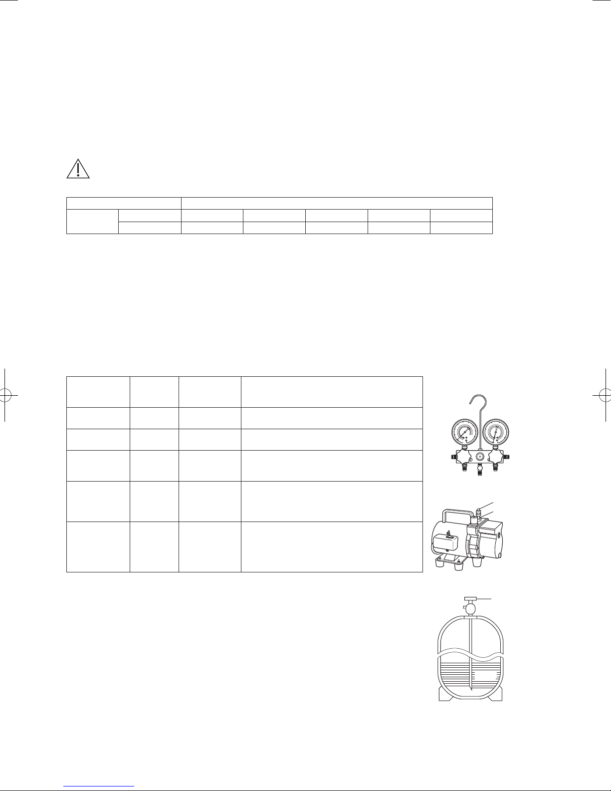
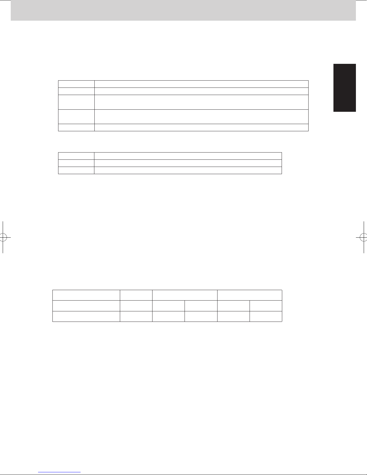
3. Different tools required
3-1. Tool specifications have been changed due to the characteristics of R410A.
Some tools for R22- and R407C-type refrigerant systems cannot be used.
Item New tool?
R407C tools
compatible
with R410A?
Remarks
Manifold gauge
Manifold gauge Yes No Types of refrigerant, refrigerating machine oil,
and pressure gauge are different.
Charge hose Yes No To resist higher pressure, material must be
changed.
Vacuum pump Yes Yes Use a conventional vacuum pump if it is equipped
with a check valve. If it has no check valve,
purchase and attach a vacuum pump adapter.
Leak detector Yes No Leak detectors for CFC and HCFC that react to
chlorine do not function because R410A contains
no chlorine. Leak detectors for HFC134a can be
used for R410A.
Vacuum pump
Outlet
Inlet
Flaring oil Yes No For systems that use R22, apply mineral oil
(Suniso oil) to the flare nuts on the tubing to
prevent refrigerant leakage. For machines that
use R407C or R410A, apply synthetic oil (ether
oil) to the flare nuts.
* Using tools for R22 and R407C and new tools for R410A together can cause defects.
3-2. Use R410A exclusive cylinder only.
Single-outlet valve
(with siphon tube)
Liquid refrigerant should be
recharged with the cylinder
standing on end as shown.
Valve
Liquid
Check the amount of refrigerant in the system and
floor space of the room according to the legislation on
refrigerant drainage. If there is no applicable legislation,
follow the standards described below.
The room in which the air conditioner is to be installed
requires a design that in the event of refrigerant gas
leaking out, its density will not exceed a set limit.
The refrigerant (R410A), which is used in the air conditioner,
is safe, without the toxicity or combustibility of ammonia, and
is not restricted by laws imposed to protect the ozone layer.
However, since it contains more than air, it poses the risk of
suffocation if its density should rise excessively. Suffocation
from leakage of refrigerant is almost non-existent. With the
recent increase in the number of high density buildings,
however, the installation of multi air conditioner systems is
on the increase because of the need for effective use of floor
space, individual control, energy conservation by curtailing heat
and carrying power, etc.
Most importantly, the multi air conditioner system is able
to replenish a large amount of refrigerant compared to
conventional individual air conditioners. If a single unit of the
multi air conditioner system is to be installed in a small room,
select a suitable model and installation procedure so that if the
refrigerant accidentally leaks out, its density does not reach the
limit (and in the event of an emergency, measures can be made
before injury can occur).
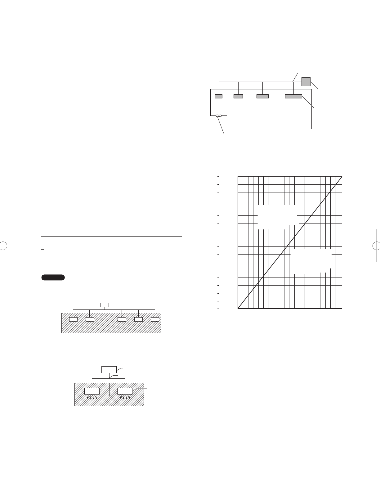
In a room where the density may exceed the limit, create an
opening with adjacent rooms, or install mechanical ventilation
combined with a gas leak detection device. The density is as
given below.
< Density limit (kg/m
The density limit of refrigerant which is used in multi air
conditioners is 0.44 kg/m
Total amount of refrigerant (kg)
Min. volume of the indoor unit installed room (m
3
)
3
(ISO 5149).
3
)
NOTE
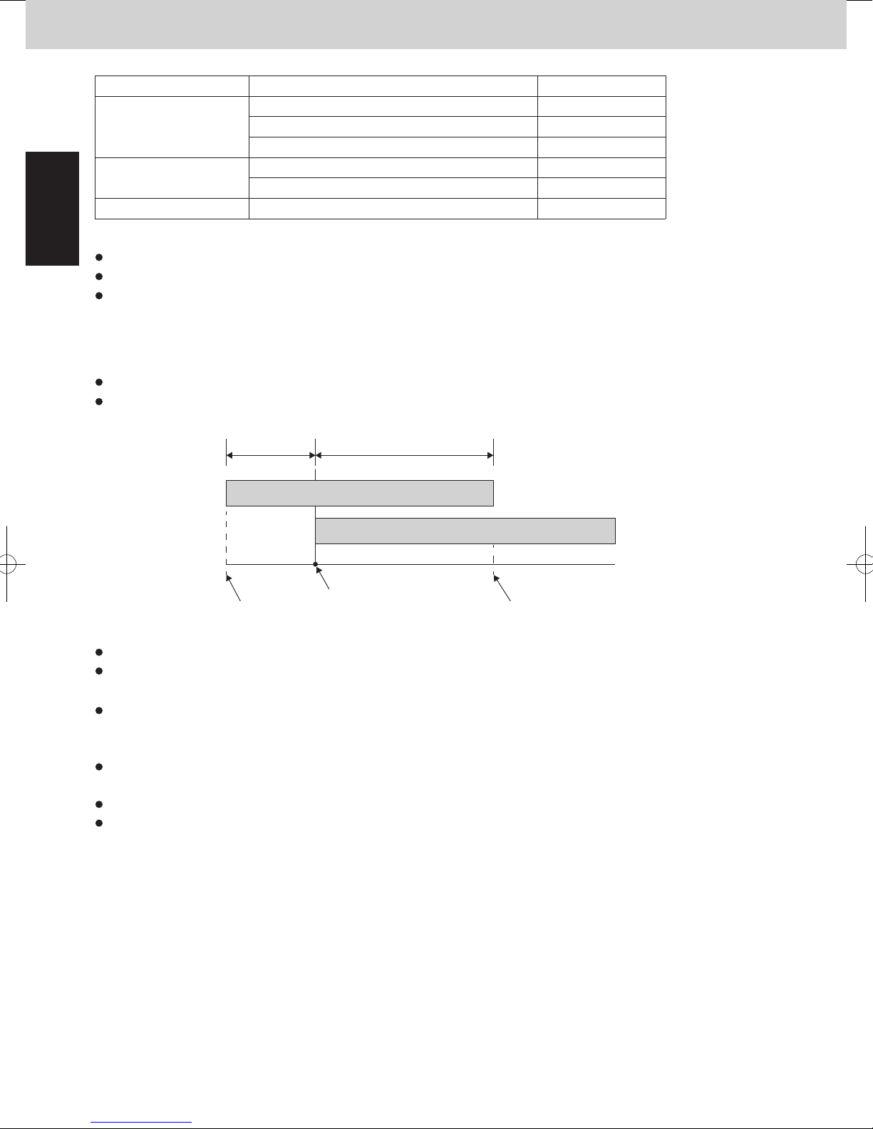
1. The standards for minimum room volume are as follows.
(1) No partition (shaded portion)
(3) If an indoor unit is installed in each partitioned room and
the refrigerant tubing is interconnected, the smallest room
of course becomes the object. But when mechanical
ventilation is installed interlocked with a gas leakage
detector in the smallest room where the density limit is
exceeded, the volume of the next smallest room becomes
the object.
Very
small
room
Small
room
Mechanical ventilation device – Gas leak detector
Medium
room
Large room
2. The minimum indoor floor space compared with the
amount of refrigerant is roughly as follows: (When the
ceiling is 2.7 m high)
3
2
m
m
229.5
85
80
216.0
75
202.5
70
189.0
Range below the
density limit of
0.44 kg/m³
(Countermeasures
not needed)
20100 30 40 60 70 80 90 10050
Total amount of refrigerant
65
175.5
60
162.0
55
148.5
50
135.0
45
121.5
40
108.0
35
94.5
30
81.0
Min. indoor volume
25
Min. indoor floor area
(when the ceiling is 2.7 m high)
67.5
20
54.0
40.5
15
10
27.0
5
13.5
0
0.0
Refrigerant tubing
Outdoor unit
Indoor unit
Range above the
density limit of
0.44 kg/m³
(Countermeasures
needed)
(2) When there is an effective opening with the adjacent room
for ventilation of leaking refrigerant gas (opening without
a door, or an opening 0.15% or larger than the respective
floor spaces at the top or bottom of the door).
Outdoor unit
Refrigerant tubing
Indoor unit
kg
v
Precautions for Installation Using New Refrigerant
1. Care regarding tubing
1-1. Process tubing
● Material: Use seamless phosphorous deoxidized copper tube for refrigeration. Wall thickness shall comply with the applicable
legislation. The minimal wall thickness must be in accordance with the table below.
● Tubing size: Be sure to use the sizes indicated in the table below.
For the renewal tubing size, refer to the Technical Data.
● Use a tube cutter when cutting the tubing, and be sure to remove any flash. This also applies to distribution joints (optional).
● When bending tubing, use a bending radius that is 4 times the outer diameter of the tubing or larger.
CAUTION
Copper tube
1-2. Prevent impurities including water, dust and oxide from entering the tubing. Impurities can cause R410A refrigerant deterioration
and compressor defects. Due to the features of the refrigerant and refrigerating machine oil, the prevention of water and other
impurities becomes more important than ever.
2. Be sure to recharge the refrigerant only in liquid form.
2-1. Since R410A is a non-azeotrope, recharging the refrigerant in gas form can lower performance and cause defects in the unit.
2-2. Since refrigerant composition changes and performance decreases when gas leaks, collect the remaining refrigerant and recharge
the required total amount of new refrigerant after fixing the leak.
3. Different tools required
3-1. Tool specifications have been changed due to the characteristics of R410A.
Some tools for R22- and R407C-type refrigerant systems cannot be used.
Item New tool?
Manifold gauge Yes No Types of refrigerant, refrigerating machine oil,
Charge hose Yes No To resist higher pressure, material must be
Vacuum pump Yes Yes Use a conventional vacuum pump if it is equipped
Leak detector Yes No Leak detectors for CFC and HCFC that react to
Flaring oil Yes No For systems that use R22, apply mineral oil
* Using tools for R22 and R407C and new tools for R410A together can cause defects.
3-2. Use R410A exclusive cylinder only.
Use sufficient care in handling the tubing. Seal the tubing ends with caps or tape to prevent dirt,
moisture, or other foreign substances from entering. These substances can result in system
malfunction.
Unit: mm
Material Temper - O (Soft copper tube)
Outer diameter 6.35 9.52 12.7 15.88 19.05
Wall thickness 0.8 0.8 0.8 1.0 1.2
R407C tools
compatible
with R410A?
Remarks
and pressure gauge are different.
changed.
with a check valve. If it has no check valve,
purchase and attach a vacuum pump adapter.
chlorine do not function because R410A contains
no chlorine. Leak detectors for HFC134a can be
used for R410A.
(Suniso oil) to the flare nuts on the tubing to
prevent refrigerant leakage. For machines that
use R407C or R410A, apply synthetic oil (ether
oil) to the flare nuts.
Single-outlet valve
(with siphon tube)
Liquid refrigerant should be
recharged with the cylinder
standing on end as shown.
Manifold gauge
Vacuum pump
Outlet
Inlet
Valve
Liquid
vi
Important Information Regarding The Refrigerant Used
This product contains fluorinated greenhouse gases. Do not vent gases into the atmosphere.
Refrigerant type: R410A
(1)
GWP
value: 2088
(1)
GWP = global warming potential
Periodical inspections for refrigerant leaks may be required depending on European or local legislation.
Please contact your local dealer for more information.
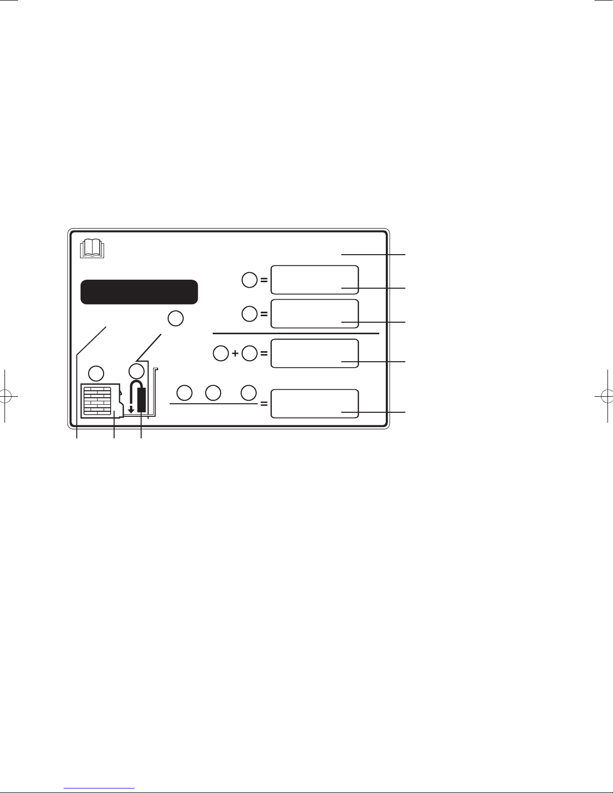
Please fill in with indelible ink,
■ 1: the factory refrigerant charge of the product
■ 2: the additional refrigerant amount charged in the field
■ 1 + 2: the total refrigerant charge
■ (1 + 2) x 3/1000: CO
on the refrigerant charge label supplied with the product.
The filled out label must be adhered in the proximity of the product charging port (e.g. onto the inside of the service cover).
2
equivalent in tons; multiply the total refrigerant charge by GWP value, then divided by 1000.
This product contains fluorinated greenhouse gases.
CO2 equivalent amount is shown in “CO2 eq.”
1
R410A
GWP : 2088
1
2
3
“CO2 eq.”
( ) x
1 2 3
+
1 000
* English text printed on this label is original. Each
7
1. Factory refrigerant charge of the product: see unit name plate
2. Additional refrigerant amount charged in the field
3. Total refrigerant charge
4. Contains fluorinated greenhouse gases
5. Outdoor unit
6. Refrigerant cylinder and manifold for charging
7. GWP(global warming potential) of the refrigerant used in this product
8. CO
56
2
equivalent of fluorinated greenhouse gases contained in this product
2
1 2
language label will be sealed on this original text.
4
kg
1
kg
2
kg
3
ton
8
vii

—
CONTENTS
—
Section 1: CONTROL FUNCTIONS - Outdoor Unit ............................. 1-1
1. Introduction ............................................................. 1-2
2. Compressor Control ...................................................... 1-3
3. Output of PCB .......................................................... 1-10
4. Outdoor Unit Fan Control .................................................. 1-12
5. Outdoor Unit CCU (command controller unit) Control ............................ 1-16
6. Oil Control ............................................................. 1-21
7. 4-Way Valve Adjustment Control ............................................ 1-23
8. Defrost Control ......................................................... 1-24
9. Demand Control ........................................................ 1-26
10. Other Functions ......................................................... 1-30
11. Detailed Settings in EEPROM of Outdoor Unit ................................. 1-33
12. Outdoor Unit Control PCB ................................................. 1-35
13. Electrical Data .......................................................... 1-42
Section 2: CONTROL FUNCTIONS - Indoor Unit .............................. 2-1
1. Room Temperature Control ................................................. 2-2
2. Heating Standby ......................................................... 2-4
3. Automatic Fan Speed Control ............................................... 2-5
4. Indoor Unit MOV Control ................................................... 2-6
5. Drain Pump Control ...................................................... 2-6
6. Automatic Heating / Cooling Control .......................................... 2-7
7. Discharge Air Temperature Control ........................................... 2-8
8. RAP Valve Kit Control ..................................................... 2-8
9. Automatic Flap Control .................................................... 2-9
10. Filter Sign .............................................................. 2-9
11. Fan Control during Dry Mode .............................................. 2-10
12. Ventilation Fan Output .................................................... 2-11
13. T10 Terminal ........................................................... 2-11
14. Parameter ............................................................. 2-12
Section 3: OUTDOOR UNIT REPAIR PROCEDURES ........................... 3-1
1. Removing Panels ......................................................... 3-2
2. Discharging Compressor Oil ................................................ 3-3
3. Recovering Refrigerant .................................................... 3-4
4. Checking for Leakage After Repair ........................................... 3-9
5. Evacuating System ...................................................... 3-10
6. Charging Compressor Oil ................................................. 3-11
7. Pumping Out Refrigerant from Outdoor Unit ................................... 3-15
8. Compressor ............................................................ 3-18
viii

Section 4: OUTDOOR UNIT MAINTENANCE REMOTE CONTROLLER ............ 4-1
1. Overview ............................................................... 4-2
2. Functions ............................................................... 4-3
3. Ordinary Display Controls and Functions ...................................... 4-4
4. Monitoring Operations ..................................................... 4-9
5. Outdoor Unit Alarm History Monitor ......................................... 4-11
6. Mode Settings .......................................................... 4-12
Section 5: REMOTE CONTROLLER FUNCTIONS ............................. 5-1
1. Simple Settings Function ................................................... 5-2
2. Detailed Settings Function .................................................. 5-8
3. Remote Controller Servicing Functions ....................................... 5-18
Section 6: TROUBLE DIAGNOSIS .......................................... 6-1
1. Contents of Remote Controller Switch Alarm Display .............................6-2
2. Outdoor Unit Control Panel LED Display ...................................... 6-4
3. Mini VRF Alarm Codes .................................................... 6-5
4. Inspection and Characteristics of Parts ...................................... 6-22
5. Test Pin ............................................................... 6-25
6. Symptom: Thermostat in OFF continues or cycles OFF & ON too frequently .......... 6-26
Section 7: TEST RUN. . . . . . . . . . . . . . . . . . . . . . . . . . . . . . . . . . . . . . . . . . . . . . . . . . . . . 7-1
1. Preparing for Test Run ..................................................... 7-2
2. Test Run Procedure ....................................................... 7-3
3. Main Outdoor Unit P.C.Board Setting .......................................... 7-4
4. Auto Address Setting ...................................................... 7-9
5. Setting Test Run Remote Controller. . . . . . . . . . . . . . . . . . . . . . . . . . . . . . . . . . . . . . . . . . 7-15
6. Caution for Pump Down ................................................... 7-16
7. Self-Diagnosis Function Table and Contents of Alarm Display ..................... 7-16
ix

Mini VRF SYSTEM
Control Functions - Outdoor unit
1
Contents
1. CONTROL FUNCTIONS - Outdoor unit
1. Introduction ........................................................... 1-2
2. Compressor Control .................................................... 1-3
3. Output of PCB ........................................................ 1-10
4. Outdoor Unit Fan Control ............................................... 1-12
5. Outdoor Unit CCU (command controller unit) Control ....................... 1-16
6. Oil Control ........................................................... 1-21
7. 4-Way Valve Adjustment Control ......................................... 1-23
8. Defrost Control ....................................................... 1-24
9. Demand Control ....................................................... 1-26
10. Other Functions ....................................................... 1-30
11. Detailed Settings in EEPROM of Outdoor Unit ..............................1-33
12. Outdoor Unit Control PCB ..............................................1-35
13. Electrical Data ........................................................1-42
1 - 1
Mini VRF SYSTEM
Control Functions - Outdoor unit
1
1. Introduction
Mini VRF SYSTEM is a multi system that is connected to a single outdoor unit. The outdoor unit contains an inverter
compressor.
To operate this system, the below settings must be made at the time of the test run.
Table 1-1
Setting item
System address 1 System 1 – 30
No. of indoor units 1 1 – 12 units
Table 1-2
Maximum number of connected indoor units 7 (10) 8 (12) 9 (12)
The numbers in parenthesis are available with the capacity of 1.5 kW indoor unit connection.
Be sure to connect indoor units so that the resulting indoor-outdoor capacity ratio (total capacity of all indoor units
compared with the outdoor unit capacity) is within the range of 50% – 130%.
At shipment
from factory
Settable range
4 HP 5 HP 6 HP
1 - 2
Mini VRF SYSTEM
Control Functions - Outdoor unit
1
2. Compressor Control
(1) Compressors Mounted in the Outdoor Units
Type of outdoor unit 4HP 5HP 6HP
Compressor
* The inverter compressor is operated according to the load and does not operate beyond outdoor unit capacity.
Inverter compressor
(High pressure rotary)
● ● ●
(2) Operating Frequency Range of Inverter Compressor
The inverter compressor can operate within the range in the table below.
1
When the high pressure is over 2.8MPa, the upper limit frequency is restricted.
2
If the low pressure is over 1.6MPa during operation of the inverter compressor, the system is stopped.
(P27: Pre-trip)
Type of outdoor unit 4HP 5HP 6HP
Minimum frequency (Hz) *1 15.0 15.0 15.0
Maximum frequency (Hz) *2 63.0 79.0 95.0
* The frequency range in the table above is subject to change without notice.
*1 The minimum Hz changes according to the outdoor air temperature during cooling operation.
*2
• The upper limit frequency is sometimes restricted to 54.0Hz until the compressor gets warmer.
• During special control (4-way valve adjustment control, system oil recovery control or defrost control) the
maximum frequency is limited.
• In heating low temperature operation, the frequency may be larger than the value in the table.
1 - 3

Mini VRF SYSTEM
Control Functions - Outdoor unit
1
2. Compressor Control
2WAY VRF SYSTEM
Control Functions
3. Compressor Control
Compressor capacity can increase
6.5+ α
Compressor capacity
cannot increase
Compressor capacity decreases
Max. load level
15
0
6.0 + α
3.0 + α
deg
2.5+ α
Te_tgt_max. 6.0+ α
Te_tgt_min. 3.0+ α
16.0
unit: °C
13.0
30
11.0 + α/2
8.0 + α/2
Area B
Area C
Area A
Evaporation temperature area
3. Compressor Control
2WAY VRF SYSTEM
Control Functions
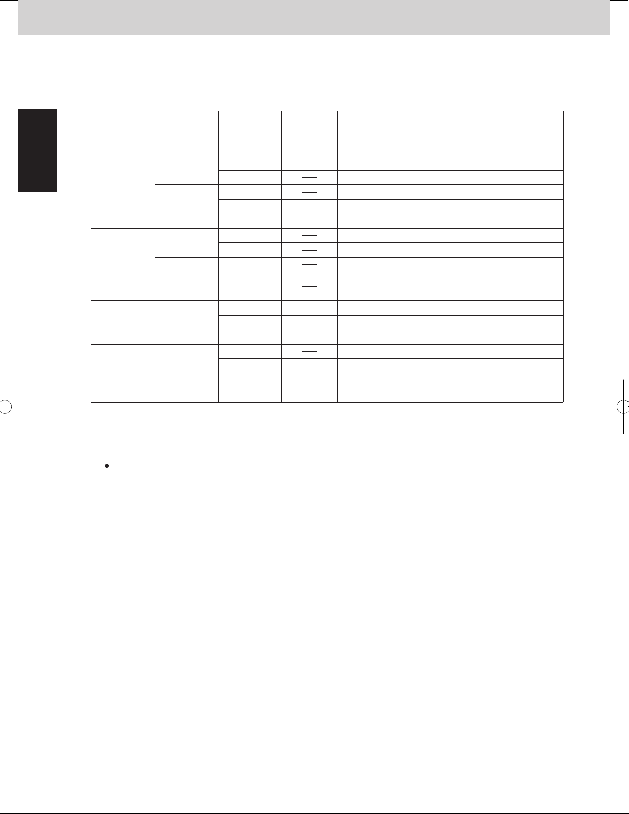
4-1. Evaporation temperature (= Te) control
The cooling capacity is adjusted with this control. It prevents freezing of the indoor unit heat
exchanger and the dew to the outside panel of the indoor unit. The capacity is adjusted according
to the following figure.
If the test run is continued for a long time, the mist may occur but it is not abnormal.*
If more than 1 indoor unit is in test run mode, the evaporation temperature control is not applicable.
Once the indoor unit is selected for the test run, the thermostat will not be turned OFF.
After the last indoor unit is operated in the test run mode, the test run is automatically cancelled
after 1 hour.
4-2. Condensation Temperature Control
Target temperature of the Area B is different between cooling and heating operation.
In Cooling Mode
The purpose of this control at cooling
is to prevent abnormal high-pressure.
1
The evaporation temperature area changes depending on the maximum load level in each indoor
unit as shown on previous page.
The Area C is regarded as Area B for 6 minutes after compressor starts.
If outdoor temperature ≥ 15°C, α is enable.
Minimum α is enable in all indoor units.
If outdoor temperature < 10°C, α is disable.
Outdoor
temperature α is enable
α
2
5
3
Indoor unit type
α : Correction Value of Te
Type D1, L1
Type P1, R1
Indoor units inapplicable to Gr 1, Gr 2
Gr 1
Gr 2
Gr 3
α is disable
start
15°C
10°C
Test run mode in cooling operation is used when the room temperature is low and the indoor unit
thermostat is not turn ON. This mode is used for operation check when the outdoor unit is fully
operated or additional refrigerant charge without stopping the system.
When the system operates in a minimum capacity, the system will continue operating for at least
6 minutes if the evaporation temperature area is Area C.
During special controls such as defrosting or oil recovering between the systems, the compressor
capacity will not be controlled by the evaporation temperature control area.
If the outdoor unit is stopped while the evaporation temperature is in Area C, the system may
operate from the lower compressor capacity when starting next time.
Test run mode
In Heating Mode
Heating capacity is adjusted with this control.
It also prevents abnormal high-pressure simultaneously.
The capacity is controlled in the following diagram.
2
(3) Forced Stopping of Compressor
Once a compressor stops, it will not start for a period of 3 minutes (3-minute forced OFF).
However, this is not applied when the compressor was forced to stop as the result of a special control
operation. (Start control, Defrost control, Refrigerant oil recovery control, etc.)
(4) Capacity Control of Compressor (Roadmap Control)
Capacity control of compressor (start & stop of compressor and increase & decrease of inverter frequency)
1
are controlled according to the numerical value of the pressure sensor installed at the outdoor unit and the
temperature sensor installed at the indoor unit heat exchanger.
* The pressure detected by the pressure sensor is converted to the saturated temperature.
This control is performed every 30 seconds.
2
When cooling operation, evaporation temperature (= antifreeze control) and condensation temperature
3
(= high pressure prevention control) are applied.
When heating operation, condensation temperature (= high pressure prevention control) is applied.
Definition of evaporation temperature (Te)
Lowest temperature of all indoor units’ evaporation temperature (E1, E3) in the system including the
stopped indoor units
Definition of condensation temperature (Tc)
Outdoor units’ high pressure saturated temperature
Load level varies from a minimum of 0 to a maximum of 30 on 1 to 1 basis up to 31 levels.
When the indoor unit stops (including thermostat OFF), the level shows “0”.
In the case of test run mode, the actual level implies “30” even if a PC monitor indicates “31”.
* In the case that the compressor is stopped from such as special controls, load level does not turn to “0”
The indoor unit demand level varies according to the following 2 conditions.
Load level increases when the differential temperature noted above indicates plus (+) value and
decreases when it indicates minus (-) value.
However, the types of units which are set to control the discharge temperature vary according to the
lowest value from the intake temperature difference and discharge temperature difference.
Te target and Tc target are controlled by the maximum value of all indoor units load level.
High pressure saturated temperature is converted from values detected by the high pressure sensor.
Low pressure saturated temperature is converted from values detected by the low pressure sensor.
even if the indoor unit is most likely to be in stopped state.
Intake temperature difference:
Discharge temperature difference:
Difference between indoor unit remote control set temperature and intake temperature (TA)
Difference between preset discharge setting temperature according to the type of indoor unit and
actual discharge temperature (TF)
1 - 4

Mini VRF SYSTEM
Control Functions - Outdoor unit
1
2. Compressor Control
3. Compressor Control
2WAY VRF SYSTEM
Control Functions
4-1. Evaporation temperature (= Te) control
The cooling capacity is adjusted with this control. It prevents freezing of the indoor unit heat
exchanger and the dew to the outside panel of the indoor unit. The capacity is adjusted according
to the following figure.
Evaporation temperature area
6.5+ α
Te_tgt_max. 6.0+ α
Te_tgt_min. 3.0+ α
2.5+ α
If outdoor temperature ≥ 15°C, α is enable.
Minimum α is enable in all indoor units.
If outdoor temperature < 10°C, α is disable.
Outdoor
temperature α is enable
15°C
10°C
The evaporation temperature area changes depending on the maximum load level in each indoor
unit as shown on previous page.
The Area C is regarded as Area B for 6 minutes after compressor starts.
When the system operates in a minimum capacity, the system will continue operating for at least
6 minutes if the evaporation temperature area is Area C.
During special controls such as defrosting or oil recovering between the systems, the compressor
capacity will not be controlled by the evaporation temperature control area.
If the outdoor unit is stopped while the evaporation temperature is in Area C, the system may
operate from the lower compressor capacity when starting next time.
Test run mode
Test run mode in cooling operation is used when the room temperature is low and the indoor unit
thermostat is not turn ON. This mode is used for operation check when the outdoor unit is fully
operated or additional refrigerant charge without stopping the system.
If the test run is continued for a long time, the mist may occur but it is not abnormal.*
If more than 1 indoor unit is in test run mode, the evaporation temperature control is not applicable.
Once the indoor unit is selected for the test run, the thermostat will not be turned OFF.
After the last indoor unit is operated in the test run mode, the test run is automatically cancelled
after 1 hour.
deg
Compressor capacity can increase
Area A
Compressor capacity
cannot increase
Compressor capacity decreases
start
α is disable
Area B
Area C
α : Correction Value of Te
Gr 1
Gr 2
Gr 3
16.0
13.0
8.0 + α/2
0
Max. load level
Indoor unit type
α
Type D1, L1
2
Type P1, R1
5
Indoor units inapplicable to Gr 1, Gr 2
3
11.0 + α/2
15
unit: °C
6.0 + α
3.0 + α
30
4-2. Condensation Temperature Control
Target temperature of the Area B is different between cooling and heating operation.
In Cooling Mode
1
The purpose of this control at cooling
is to prevent abnormal high-pressure.
In Heating Mode
2
Heating capacity is adjusted with this control.
It also prevents abnormal high-pressure simultaneously.
The capacity is controlled in the following diagram.
1 - 5
Mini VRF SYSTEM
Control Functions - Outdoor unit
1
2. Compressor Control
2WAY VRF SYSTEM
Control Functions
3. Compressor Control
3. Compressor Control
2WAY VRF SYSTEM
Control Functions
* Discharge temperature that is used for this control is the highest temperature among all compressors.
When the temperature falls in the Area D (over PX temperature), the operation stops within 0 to
30 seconds at the interval of the roadmap control.
After Tc falls in the Area D and the thermostat is turned OFF, the system may resume operating
from the lower compressor capacity.
Test Run
Test run mode in heating operation is used when the room temperature is high and the indoor unit
thermostat is not turned ON. This mode is used for operation check when the outdoor unit is fully
operated or additional refrigerant charge without stopping the system.
When the system operates in a minimum capacity, the system will continue operating for at least
6 minutes if the condensation temperature area is the Area C.
If it maintains in the Area C, the thermostat may turn OFF.
Once the indoor unit is selected for the test run, the thermostat will not be turned OFF.
However, condensation temperature control is performed in order to prevent the high load
according to the figure shown on previous page.
After the last indoor unit is operated in the test run mode, the test run is automatically cancelled
after 1 hour.
4-3. Protection Control
Compressor stops
Horsepower decreases
Horsepower cannot increase
Horsepower can increase
Capacity goes down 2.0HP
Capacity goes down 1.0HP
Capacity goes down 0.5HP
Compressor discharge temperature protection
The compressor capacity is controlled according to the figure below.
1
Low pressure protection control
In order to prevent the excessive decrease of low pressure, the compressor capacity is controlled
according to the figure below.
2
106
105
104
100
Capacity goes down 0.3HP
96
94
°C
No restriction
Capacity goes up slowly
0.25
0.20
Capacity cannot increase
Capacity goes down
H06 trip (Continuous for 2 minutes)
0.17
0.06
H06 trip0.02
Low pressure
MPa
・Standard setting (at the shipment)
°C °C
PX=58.0 PX=58.0
57.9
55.1
55.0
53.0
52.9
・Renewal setting (JP001 cut on all outdoor unit PCB) * For details, see Section 9 of Technical Data.
°C °C
52.5
PX=
52.5-0.1
49.1
49.0
47.0
46.9
Thermostat
OFF
Horsepower
decrease
Horsepower
increase
prohibited
Horsepower
increase
possible
Thermostat
OFF
Horsepower
decrease
Horsepower
increase
prohibited
Horsepower
increase
possible
Area D
Area C
Area B
Area A
Area D
Area C
Area B
Area A
Thermostat
OFF
57.9
Horsepower
decrease
50.1
50.0
48.0
47.9
PX=
52.5-0.1
52.5
48.1
48.0
47.0
46.9
Horsepower
increase
prohibited
Horsepower
increase
possible
Thermostat
OFF
Horsepower
decrease
Horsepower
increase
prohibited
Horsepower
increase
possible
Area D
Area C
Area B
Area A
Area D
Area C
Area B
Area A
42.0
34.0
33.0
Max. required level
40.5
33.5
32.5
40.5
15 300
39.5
°C
50.0
48.0
°C
48.0
47.0
15 300
Max. required level
1 - 6
Mini VRF SYSTEM
Control Functions - Outdoor unit
1
2. Compressor Control
3. Compressor Control
2WAY VRF SYSTEM
Control Functions
When the temperature falls in the Area D (over PX temperature), the operation stops within 0 to
30 seconds at the interval of the roadmap control.
After Tc falls in the Area D and the thermostat is turned OFF, the system may resume operating
from the lower compressor capacity.
When the system operates in a minimum capacity, the system will continue operating for at least
6 minutes if the condensation temperature area is the Area C.
If it maintains in the Area C, the thermostat may turn OFF.
Test Run
Test run mode in heating operation is used when the room temperature is high and the indoor unit
thermostat is not turned ON. This mode is used for operation check when the outdoor unit is fully
operated or additional refrigerant charge without stopping the system.
Once the indoor unit is selected for the test run, the thermostat will not be turned OFF.
However, condensation temperature control is performed in order to prevent the high load
according to the figure shown on previous page.
After the last indoor unit is operated in the test run mode, the test run is automatically cancelled
after 1 hour.
4-3. Protection Control
Compressor discharge temperature protection
1
The compressor capacity is controlled according to the figure below.
* Discharge temperature that is used for this control is the highest temperature among all compressors.
°C
106
105
104
100
96
94
Compressor stops
Capacity goes down 2.0HP
Capacity goes down 1.0HP
Horsepower decreases
Capacity goes down 0.5HP
Capacity goes down 0.3HP
Horsepower cannot increase
Horsepower can increase
Low pressure protection control
2
In order to prevent the excessive decrease of low pressure, the compressor capacity is controlled
according to the figure below.
Low pressure
MPa
0.25
0.20
0.17
0.06
No restriction
Capacity goes up slowly
Capacity cannot increase
Capacity goes down
H06 trip (Continuous for 2 minutes)
H06 trip0.02
1 - 7
Mini VRF SYSTEM
Control Functions - Outdoor unit
1
2. Compressor Control
Current protection
3
This restriction protects the compressor and controls the compressor electric current simultaneously.
The current limitation value changes to “normal status” and “overload status” according to the outdoor
temperature.
The primary and secondary current values of the inverter compressors are measured.
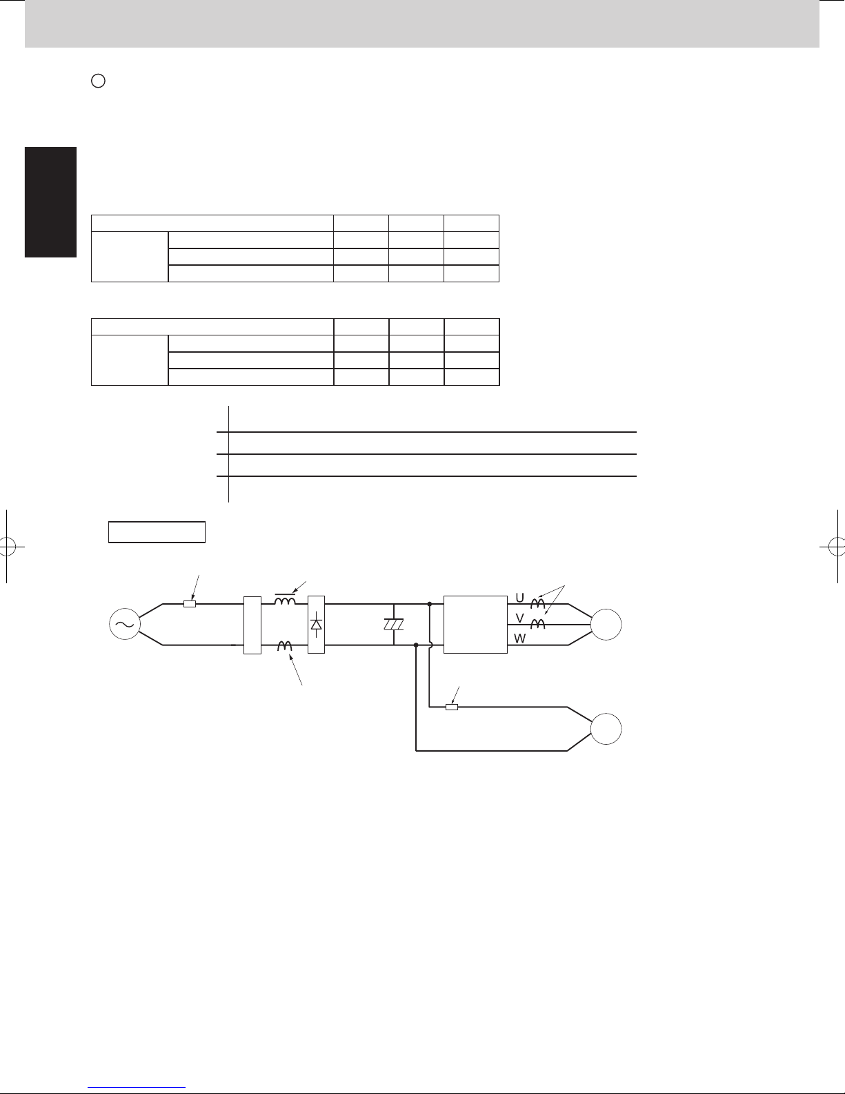
U-4LE2E5, U-5LE2E5, U-6LE2E5
unit: Ampere
Type of outdoor unit 4HP 5HP 6HP
Limit current 1 32.2 32.2 32.2
Primary
* Normally, maximum current is limited in demand control shown on page 1-26.
Secondary
Maximum current 1 H 25.0 25.0 28.0
Maximum current 1 L 24.0 24.0 27.0
Type of outdoor unit 4HP 5HP 6HP
Limit current 2 24.5 24.5 24.5
Maximum current 2 H 21.0 21.0 21.0
Maximum current 2 L 20.0 20.0 20.0
Limit current 1, 2
Max. current 1H, 2H
Max. current 1L, 2L
Inverter layout
FuseFuse
Power
supply
L
N
Stop If this current is detected at regular intervals, alarm appears.
Frequency of inverter compressor goes down.
Frequency of inverter compressor cannot increase.
Frequency of inverter compressor can increase.
Noise filter
Reactor
Diode
bridge
Primary CT1
IPM
(CM1)
Fuse
Secondary CT
Compressor
Fan motor
1 - 8
Mini VRF SYSTEM
Control Functions - Outdoor unit
1
2. Compressor Control
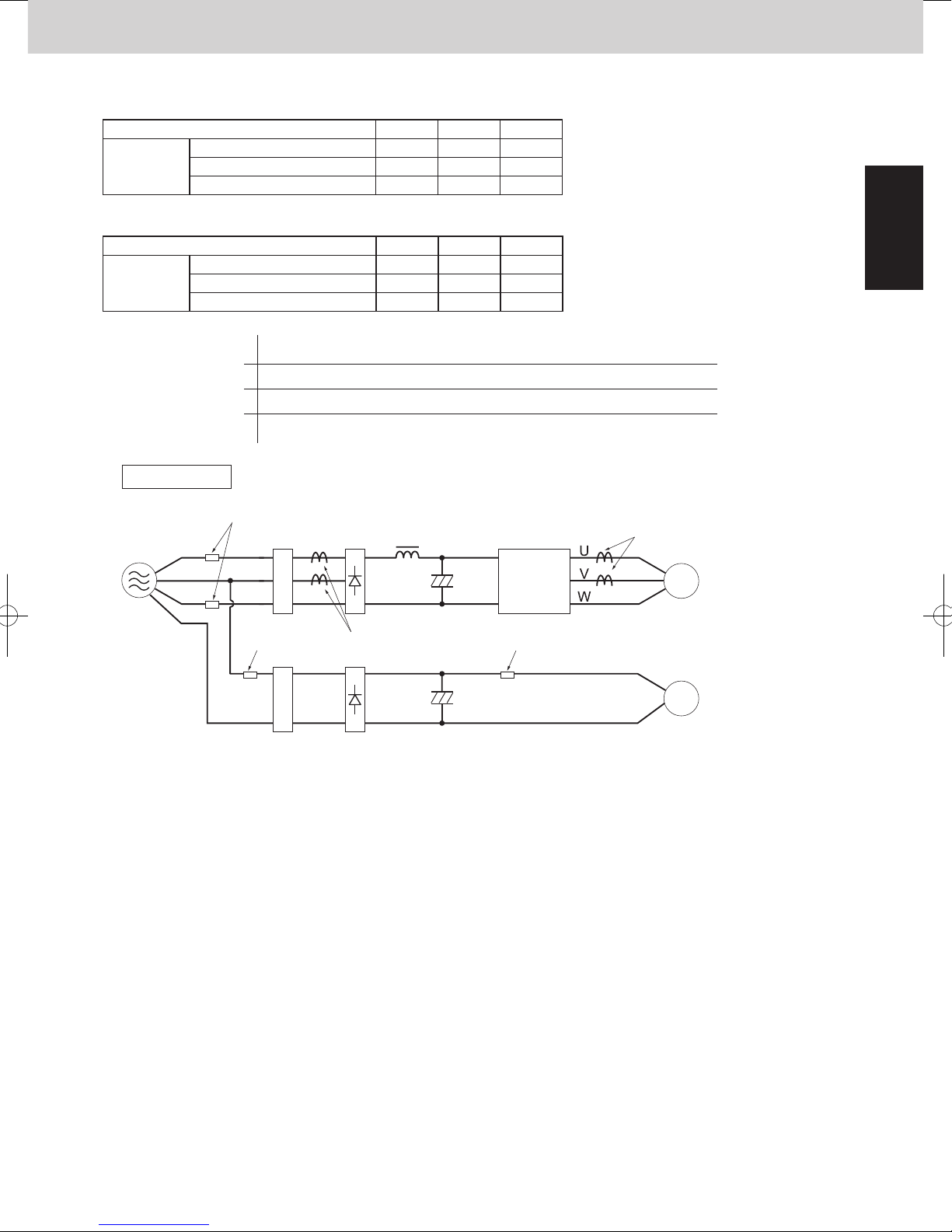
U-4LE2E8, U-5LE2E8, U-6LE2E8
unit: Ampere
Type of outdoor unit 4HP 5HP 6HP
Limit current 1 14.0 14.0 14.0
Primary
* Normally, maximum current is limited in demand control shown on page 1-26.
Secondary
Limit current 1, 2
Max. current 1H, 2H
Max. current 1L, 2L
Maximum current 1 H 8.0 10.0 12.0
Maximum current 1 L 7.0 9.0 11.0
Type of outdoor unit 4HP 5HP 6HP
Limit current 2 15.2 15.2 15.2
Maximum current 2 H 12.2 12.2 12.2
Maximum current 2 L 11.2 11.2 11.2
Stop If this current is detected at regular intervals, alarm appears.
Frequency of inverter compressor goes down.
Frequency of inverter compressor cannot increase.
Frequency of inverter compressor can increase.
Inverter layout
Power
supply
L1
L2
L3
N
FuseFuse
Noise filter
Fuse
Noise filter
Diode
bridge
Primary CT
Diode
bridge
Reactor
(CM1)
Fuse
IPM
Secondary CT
Compressor
Fan motor
1 - 9
Mini VRF SYSTEM
Control Functions - Outdoor unit
1
3. Output of PCB
4. Special Control
2WAY VRF SYSTEM
Control Functions
2WAY VRF SYSTEM
Control Functions
4. Special Control
(3) O2 Valve [O2] *O2 valve is the local supply parts.
This valve works when the outdoor unit receives signal of the refrigerant leakage from the indoor unit.
(5) Crankcase Heater Control [CH]
When the compressor stops, the crankcase heater of its own compressor is turned ON / OFF in the following
conditions.
●
When the outdoor air temperature < 25°C :ON
●
When the outdoor air temperature ≥ 27°C : OFF
The indoor unit that transmits the signal of the refrigerant leakage gives “P14”alarm.
To activate this function, it is necessary to set it to EEPROM on the main outdoor PCB and indoor PCB.
EEPROM setting in main outdoor unit
CODE: C1
Setting No.
Setting No.
0
0
1
1
2
This function invalid (factory preset mode)
3
Never use
This valve is turned OFF when the system is normal.
This valve is turned ON when the outdoor unit receives signal from the indoor unit
This valve is turned ON when the system is normal.
This valve is turned OFF when the outdoor unit receives signal from the indoor unit
EEPROM setting in indoor unit
CODE: 0B
Function of EXCT plug short-circuit
Indoor unit does thermostat OFF
(factory preset mode)
Indoor unit gives “P14”alarm and transmits the refrigerant leakage signal.
4-1. Type of Electronic control valves
4-2. Power Initialization
MOV1 is for adjusting refrigerant flow amount of outdoor heat exchanger.
MOV4 is for adjusting refrigerant flow amount of Sub cooler.
If no indoor units have started (even once) after the power supply to the outdoor unit, the MOV holds the 480
pulses (fully open).
4-3. Control of Electronic control valves
Electronic control valves for heat exchanger control according to the operation mode.
Cooling HeatingMode of system
Compressor
MOV1 and MOV4 (pulse)
Stop
Stop
0
Operation
480
Stop
0*
1
Operation
0 ~ 480*
3
Stop
0*
2
*When the indoor unit receives the signal for operation request from the control equipment, the pulse turns
other than the 480 pulses (regardless of the thermostat ON/OFF or operating ON/OFF).
It is necessary to switch ON the power supply again if the 480 pulses are required.
*1 However, 100 pulses remain for 2 minutes after unit stopped.
*2 When the outdoor unit stops and low pressure ≤ 0.16 MPa, 100 pulses remain for 30 seconds.
*3 If the outdoor unit is operating in heating mode, electronic control valves perform SH control.
SH control adjusts the difference of temperature between the liquid and gas temperature to -1 ~ 5 degrees
Celsius.
(4) Electronic Control Valves [MOV1, MOV4]
Items Remarks Indication on PCB
Solenoid valve
Motor Operated Valve
Crankcase heater
(1) 4-way Valve [20S]
This valve turns OFF at cooling mode, and turns ON at heating mode.
Regarding the operation in defrost control, see the section “8. Defrost Control”.
When the outdoor unit stops, the 4-way valve maintains in the same state as before.
(2) Oil Recovery Valve [ORVR]
The purpose of this valve is to recover oil from the oil separator to the compressor and is to adjust the
capacity and pressure.
This valve is always OFF when outdoor unit is stopped.
This valve turns ON for 5 seconds before the inverter compressor starts. After the inverter compressor starts, the
valve is ON for 2 minutes. After that, it turns OFF.
This valve turns ON for 30 seconds after the outdoor unit stops. After that, it turns OFF.
This valve turns ON when the high pressure is too high.
This valve turns OFF when the high pressure goes down.
This valve turns ON when the high pressure switch is activated.
This valve stays ON for 10 seconds after the high pressure switch returns in normal.
After that, it turns OFF.
This valve might turn ON when the system capacity is excessive although the inverter compressor operates at
minimum frequency.
This valve turns ON while the discharge temperature of the compressor is low.
This valve turns ON during the operation of 4-way valve control.
Valve turns ON Valve turns OFF
4-way valve
Oil recovery valve
2 valve
O
MOV for heat exchanger
MOV for Sub cooler
Crankcase heater
5 seconds 2 minutes
ORVR valve
Compressor
Inverter compressor starts
20S
ORVR
O
2
MOV1
MOV4
CH
1 - 10
Mini VRF SYSTEM
Control Functions - Outdoor unit
1
3. Output of PCB
2WAY VRF SYSTEM
Control Functions
4. Special Control
(3) O2 Valve [O2] *O2 valve is the local supply parts.
This valve works when the outdoor unit receives signal of the refrigerant leakage from the indoor unit.
The indoor unit that transmits the signal of the refrigerant leakage gives “P14”alarm.
To activate this function, it is necessary to set it to EEPROM on the main outdoor PCB and indoor PCB.
EEPROM setting in main outdoor unit
CODE: C1
Setting No.
0
1
2
3
EEPROM setting in indoor unit
CODE: 0B
Setting No.
0
1
(4) Electronic Control Valves [MOV1, MOV4]
4-1. Type of Electronic control valves
MOV1 is for adjusting refrigerant flow amount of outdoor heat exchanger.
MOV4 is for adjusting refrigerant flow amount of Sub cooler.
This function invalid (factory preset mode)
This valve is turned OFF when the system is normal.
This valve is turned ON when the outdoor unit receives signal from the indoor unit
This valve is turned ON when the system is normal.
This valve is turned OFF when the outdoor unit receives signal from the indoor unit
Never use
Function of EXCT plug short-circuit
Indoor unit does thermostat OFF
Indoor unit gives “P14”alarm and transmits the refrigerant leakage signal.
(factory preset mode)
4-2. Power Initialization
If no indoor units have started (even once) after the power supply to the outdoor unit, the MOV holds the 480
pulses (fully open).
*When the indoor unit receives the signal for operation request from the control equipment, the pulse turns
other than the 480 pulses (regardless of the thermostat ON/OFF or operating ON/OFF).
It is necessary to switch ON the power supply again if the 480 pulses are required.
4-3. Control of Electronic control valves
Electronic control valves for heat exchanger control according to the operation mode.
Stop
0*
Cooling HeatingMode of system
Operation
1
480
Stop
0*
2
Operation
0 ~ 480*
3
Stop
Compressor
MOV1 and MOV4 (pulse)
*1 However, 100 pulses remain for 2 minutes after unit stopped.
*2 When the outdoor unit stops and low pressure ≤ 0.16 MPa, 100 pulses remain for 30 seconds.
*3 If the outdoor unit is operating in heating mode, electronic control valves perform SH control.
SH control adjusts the difference of temperature between the liquid and gas temperature to -1 ~ 5 degrees
Celsius.
(5) Crankcase Heater Control [CH]
When the compressor stops, the crankcase heater of its own compressor is turned ON / OFF in the following
conditions.
●
When the outdoor air temperature < 25°C :ON
●
When the outdoor air temperature ≥ 27°C : OFF
Stop
0
1 - 11

Mini VRF SYSTEM
Control Functions - Outdoor unit
1
4. Outdoor Unit Fan Control
5. Outdoor Unit Fan Control
2WAY VRF SYSTEM
Control Functions
11
2WAY VRF SYSTEM
Control Functions
5. Outdoor Unit Fan Control
(4) Fixed Initial Fan Step
For the first 30 seconds after operation starts, the mode is fixed at the initial mode which was calculated from
the relationship between the outdoor air temperature and the outdoor unit horsepower.
If the outdoor unit horsepower (compressor capacity) changes dramatically, the initial mode may be
recalculated and may be again fixed for 30 seconds.
(5) Operation after Fixed Initial Fan Step
After the fixed initial fan step, the fan step is increased or decreased according to the operating conditions.
5-1. Cooling operation
* The fan step is always increased when the detected high pressure sensor temperature is 46°C or higher.
Fan step is increased when the detected high pressure saturated temperature is high, and is decreased when
the high pressure saturated temperature is low.
The fan step may be decreased when the system detects refrigerant shortage at an indoor unit.
During cooling operation, if the fan step becomes “0” and this condition maintains for 3 minutes, the fan step
is changed to “1”.
5-2. When all indoor units are operating in heating mode
If the pressure sensor temperature is low, the fan step is increased at regular intervals.
If the pressure sensor temperature is high, the fan step is decreased in order to prevent excessive loads.
The fan step may be increased when the liquid temperature of outdoor unit heat exchanger drops to 1 degrees
Celsius or below.
Selecting the silent mode results in operation that gives priority to reducing noise at the outdoor unit.
When the setting is in silent mode, the outdoor fan step and the maximum frequency is limited.
So the capacity will be decreased. However, the frequency is not limited during the special controls.
Maximum fan step & maximum frequency in silent mode
Type of outdoor unit
Silent effect
-3dB mode
-1.5dB mode
-7dB mode
-5dB mode
Fan step
Compressor frequency (Hz)
Fan step
Compressor frequency (Hz)
Fan step
Compressor frequency (Hz)
6HP
Heating Cooling
58.2
6
55.0
6
53.4
Heating
64.6
9
48.6
8
48.6
4HP
Cooling
710
Heating
64.6
9
48.6
8
48.6
5HP
Cooling
51.8
108
Fan step
Compressor frequency (Hz) 95.0 95.0
48.6
8
48.6
7
43.8
10
63.0
11 10 12
43.8
8
7
43.8
6
43.8
63.0
9
79.079.0
1310
6
51.8
6
48.6
(6) Silent Mode
(1) Number of Fan Motor
Type of outdoor unit
Number of fan motor
(2) Fan Step
These outdoor units utilize a DC fan motor that can be controlled in 0〜15 steps (0〜15 modes) in ordinary mode.
The control range is expanded to a maximum of 15 steps (15 modes) if high static-pressure mode has been set.
The fan rotating numbers will be changed according to the fan steps.
(3) Minimum Fan Step and Maximum Fan Step
These outdoor units utilize a DC fan motor that can be controlled in a maximum of 15 steps (15 modes).
However, fan modes 15 can only be used if high static pressure mode or high efficiency mode has been set.
* For information concerning EEPROM settings, refer to the field application functions.
Maximum value
Minimum value
4, 5, 6 HP
1
Standard
High static pressure
mode setting
High efficiency mode
setting
Status of heat
exchanger
Condenser
Evaporator
Condenser
Evaporator
Condenser
Evaporator
Ambient temperature ≥ 38°C
Ambient temperature < 38°C
Ambient temperature ≥ 3
Ambient temperature < 3
5HP4HP 6HP
1211 12
1110 11
1211 12
1414 14
1313 13
1515 15
1312 13
1515 15
1
1 - 12

Mini VRF SYSTEM
Control Functions - Outdoor unit
1
4. Outdoor Unit Fan Control
2WAY VRF SYSTEM
Control Functions
5. Outdoor Unit Fan Control
(4) Fixed Initial Fan Step
For the first 30 seconds after operation starts, the mode is fixed at the initial mode which was calculated from
the relationship between the outdoor air temperature and the outdoor unit horsepower.
If the outdoor unit horsepower (compressor capacity) changes dramatically, the initial mode may be
recalculated and may be again fixed for 30 seconds.
(5) Operation after Fixed Initial Fan Step
After the fixed initial fan step, the fan step is increased or decreased according to the operating conditions.
5-1. Cooling operation
Fan step is increased when the detected high pressure saturated temperature is high, and is decreased when
the high pressure saturated temperature is low.
* The fan step is always increased when the detected high pressure sensor temperature is 46°C or higher.
The fan step may be decreased when the system detects refrigerant shortage at an indoor unit.
During cooling operation, if the fan step becomes “0” and this condition maintains for 3 minutes, the fan step
is changed to “1”.
5-2. When all indoor units are operating in heating mode
If the pressure sensor temperature is low, the fan step is increased at regular intervals.
If the pressure sensor temperature is high, the fan step is decreased in order to prevent excessive loads.
The fan step may be increased when the liquid temperature of outdoor unit heat exchanger drops to 1 degrees
Celsius or below.
(6) Silent Mode
Selecting the silent mode results in operation that gives priority to reducing noise at the outdoor unit.
When the setting is in silent mode, the outdoor fan step and the maximum frequency is limited.
So the capacity will be decreased. However, the frequency is not limited during the special controls.
Maximum fan step & maximum frequency in silent mode
Type of outdoor unit
-1.5dB mode
-3dB mode
-5dB mode
-7dB mode
4HP
Silent effect
Fan step
Compressor frequency (Hz) 95.0 95.0
Fan step
Compressor frequency (Hz)
Fan step
Compressor frequency (Hz)
Fan step
Compressor frequency (Hz)
Cooling
9
63.0
8
43.8
7
43.8
6
43.8
Heating Cooling
11 10 12
63.0
10
48.6
8
48.6
7
43.8
Cooling
51.8
6
51.8
6
48.6
5HP
Heating
1310
79.079.0
108
64.6
9
48.6
8
48.6
6HP
Heating
710
58.2
6
55.0
6
53.4
64.6
9
48.6
8
48.6
1 - 13

Mini VRF SYSTEM
Control Functions - Outdoor unit
1
4. Outdoor Unit Fan Control
5. Outdoor Unit Fan Control
2WAY VRF SYSTEM
Control Functions
The system entirely becomes to the silent mode by setting in the main outdoor unit.
EEPROM setting in main outdoor unit
CODE : 05
Setting No.
0
1
2
3
4
5
6
7
8
10
11
12
Invalidity (Factory preset mode)
Mode
Capacity is given priority (*)
Capacity is given priority
Capacity is given priority
Capacity is given priority
Capacity is given priority (*)
Capacity is given priority
Capacity is given priority
Capacity is given priority
Silent is given priority (*)9
Silent is given priority
Silent is given priority
Silent is given priority
External input to PCB
Necessary
Necessary -3dB
Necessary
Necessary
Unnecessary
Unnecessary -3dB
Unnecessary
Unnecessary
Necessary
Necessary -3dB
Necessary
Necessary
Silent effect
-1.5dB
-5dB
-7dB
-1.5dB
-5dB
-7dB
-1.5dB
-5dB
-7dB
13
14
15
16
(*) Rated capacity is maintained under rated condition.
NOTE
When the setting is “external input necessary”, this function works in either of the following way
1
short circuiting “SILENT” plug on the PCB.
2
-1 Change setting the outdoor unit EEPROM CODE: 78 to “01”.
CODE: 78
Setting No.
0
1
2
-2 When setting in Quiet operation by the indoor unit address 1 remote controller (CZ-RTC5A / CZ-RTC5B):
*Regarding the method of setting Quiet operation, see the Operating Instructions provided with the
remote controller.
When the setting is “external input to PCB unnecessary”, this function always works.
When the setting is “Capacity is given priority”, this function is interrupted in the following conditions.
Cooling operation: Ambient temperature ≥ 38°C
Heating operation: Ambient temperature < 2°C
In case of selecting silent priority mode (more than “9” setting) in high load situation, the system has
possibility to stop to prevent high pressure cut.
Silent is given priority (*)
Silent is given priority
Silent is given priority
Silent is given priority
Input by indoor unit remote controller
Invalid (Factory preset mode)
Valid
Unnecessary
Unnecessary -3dB
Unnecessary
Unnecessary
-1.5dB
-5dB
-7dB
1 - 14

Mini VRF SYSTEM
Control Functions - Outdoor unit
1
4. Outdoor Unit Fan Control
(7) High Static Pressure Mode
The outdoor unit allows a high static pressure changing the settings.
The maximum permissible static pressure is 35Pa.
EEPROM setting in each outdoor unit
CODE:8F
Setting No.
0 Invalid (factory preset mode)
1 High static pressure mode 1
However, maximum fan mode is upper limit.
(8)High Efciency Mode
Theoutdoorunitallowsahighefciencymodechangingthesettings.
CODE:5F
Setting No.
0 Invalid (factory preset mode)
1 Valid
1 - 15
Mini VRF SYSTEM
Control Functions - Outdoor unit
1
5. Outdoor Unit CCU (command controller
unit) Control
6. Outdoor Unit CCU (command controller unit) Control
2WAY VRF SYSTEM
Control Functions
2WAY VRF SYSTEM
Control Functions
6. Outdoor Unit CCU (command controller unit) Control
Operating
mode of
indoor unit
Operating
mode of
outdoor unit
Operating
mode of
compressor
Thermostat
ON/OFF
MOV pulse of indoor unit
Stop
Cooling
Stop
Operation
Stop
Operation
Stop
Operation
Stop
Stop
Stop
OFF
OFF
ON
ON
Operation
20
20
20
20
20
20
20
20
20
20
20
60 ~ 480 (SH control*
1
)
65 - 480 pulses (SC control*
3
)
20
Operation
Operation
Fan (only)
Cooling
Heating
Heating
Cooling
Cooling
Heating
Heating
1-2. Indoor unit with RAP valve kit
Go to previous page and see the comments with asterisks *1 and *3.
In the case of special controls, the MOV performs a special operation.
For details, see “3. Special Control” under this section.
unit : pulse
Some actuators of indoor unit are controlled by CCU.
(1)
MOV of Indoor Unit
1-1. Indoor unit without RAP valve kit
Operating
mode of
indoor unit
Stop
Fan (only)
Cooling
Heating
*1 SH control adjusts the difference between the liquid temperature and gas temperature in indoor unit.
SH = gas temperature (E3) - liquid temperature (E1)
Target SH is 3 degrees Celsius when the load level of indoor unit is “30” or “31 (test run)”.
Target SH will be increased up to 17.5 degrees Celsius when the load level of indoor unit is low.
When the refrigerant amount in the system is adjusted, it is necessary to select test run mode that the
required level becomes “31”.
*2 MOV pulse changes to 55 for 1 minute when the MOV pulse continues to be 55 or more for 10 minutes.
The purpose of this control is to decrease the flow volume of the refrigerant so that room temperature can
be detected with less influence of heat from the refrigerant.
*3 SC control adjusts the difference in temperature between the liquid temperature in indoor unit and
high-pressure saturated temperature in outdoor unit.
SC = high-pressure sensor temperature (HPT) - liquid temperature (E1)
Target SC is 5 - 15 degrees Celsius according to the operating condition.
Operating
mode of
outdoor unit
Cooling
Heating
Cooling
Heating
Cooling
Heating
Operating
mode of
compressor
Operation
Operation
Operation
Operation
Operation
Operation
Stop
Stop
Stop
Stop
Stop
Stop
Thermostat
ON/OFF
OFF
OFF
20
20
85
65 ~ 80
(prevent remaining refrigerant )
20
20
85
65 ~ 80
(prevent remaining refrigerant)
20
20
ON
ON
60 ~ 480 (SH control*
85
55 ~ 80 (prevent remaining refrigerant,
suction temperature control*
65 - 480 pulses (SC control*
MOV pulse of indoor unit
1
)
2
)
3
)
unit : pulse
1 - 16

Mini VRF SYSTEM
Control Functions - Outdoor unit
1
5. Outdoor Unit CCU (command controller
unit) Control
2WAY VRF SYSTEM
Control Functions
6. Outdoor Unit CCU (command controller unit) Control
1-2. Indoor unit with RAP valve kit
Operating
mode of
indoor unit
Stop
Fan (only)
Cooling
Heating
Go to previous page and see the comments with asterisks *1 and *3.
In the case of special controls, the MOV performs a special operation.
For details, see “3. Special Control” under this section.
Operating
mode of
outdoor unit
Cooling
Heating
Cooling
Heating
Cooling
Heating
Operating
mode of
compressor
Stop
Operation
Stop
Operation
Stop
Operation
Stop
Operation
Stop
Operation
Stop
Operation
Thermostat
ON/OFF
OFF
ON
OFF
ON
20
20
20
20
20
20
20
20
20
20
60 ~ 480 (SH control*
20
20
65 - 480 pulses (SC control*
MOV pulse of indoor unit
1
)
3
)
unit : pulse
1 - 17
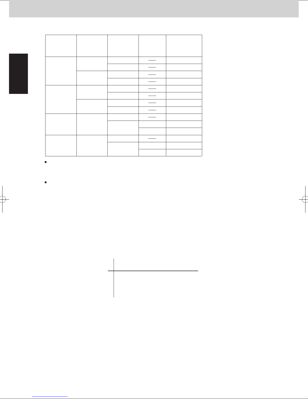
Mini VRF SYSTEM
Control Functions - Outdoor unit
1
5. Outdoor Unit CCU (command controller
unit) Control
6. Outdoor Unit CCU (command controller unit) Control
2WAY VRF SYSTEM
Control Functions
2WAY VRF SYSTEM
Control Functions
6. Outdoor Unit CCU (command controller unit) Control
3-2. Heating mode
The indoor unit fan in heating mode is stopped from the CCU in the following condition.
Discharge air temperature of indoor unit ≤ 20°C
High pressure saturated temperature (HPT) in outdoor unit≤ 25°C
Liquid temperature (E1) in indoor unit ≤ 20°C
EEPROM setting in main outdoor unit
CODE: 0C
Indoor unit
operation mode
Setting No.
0
1
2
4
6
7 (Factory
preset mode)
3
5
Movement of drain pump
Invalid
DP operates for 20 minutes and stops for 2 hours
DP operates for 20 minutes and stops for 20 minutes
DP always operates
DP operates for XX minutes when indoor unit's operation changes;
from thermostat ON or thermostat OFF → operation stopped.
DP operates for XX minutes when indoor unit's operation changes;
from thermostat ON → thermostat OFF or operation stopped.
All mode
Cooling mode
Dry mode
Heating mode
Cooling mode
Dry mode
Both Setting No. 4 and 5 functions.
DP operates for XX minutes when indoor unit's operation changes
from thermostat ON or thermostat OFF → operation stopped.
(4) Drain Pump Control
The CCU intervenes in drain pump control of the indoor
unit according to the setting in EEPROM in the outdoor unit.
The drain pump operates from the CCU control at the following condition.
DP counter ≥ 5
*The DP counter counts each oil recovery control, and 4-way Valve Adjustment Control in cooling operation.
Liquid temperature (E1) in the indoor unit which selected cooling mode < 0 °C
* Regardless of operating / stopped mode
*
To activate this function, it is necessary to set EEPROM on the main outdoor unit PCB.
*
When any of setting Nos. 4 – 7 is selected, this function works only for the type of F2, M1.
Low Silhouette Ducted type indoor unit
In Low Silhouette Ducted types, dirt might be accumulated when water collects in the drain pan for a long
term.
Therefore, the drain pump works longer to drain water surely.
(2) RAP Valve Kit
(3) Indoor Fan Speed Control
3-1. Dry mode
Operating
mode of
indoor unit
Stop
Fan (only)
Cooling
Heating
RAP valve kit state (ON/OFF) is displayed on "D" in DSBE column when the Checker software is used.
0:OFF
1:ON
In the case of special controls, the MOV performs a special operation.
For details, see “3. Special Control” under this section.
The CCU intervenes in fan control of the indoor unit according to the status of the operating mode.
The priority order of fan control by the CCU is higher than that of indoor units.
Indoor unit fan operated in the dry mode is controlled from the CCU as shown in the figure below.
Operating
mode of
outdoor unit
Cooling
Heating
Cooling
Heating
Cooling
Heating
Operating
mode of
Compressor
Stop
Operation
Stop
Operation
Stop
Operation
Stop
Operation
Stop
Operation
Stop
Operation
Thermostat
ON/OFF
OFF
OFF
RAP valve kit
ON
ON
ON/OFF
OFF
OFF
OFF
OFF
OFF
OFF
OFF
OFF
OFF
OFF
OFF
OFF
OFF
ON
+ 1.0 degrees Celsius
* DTi = ( Air intake temperature of indoor unit) - (Preset temperature by remote controller)
DTi
Preset fan speed by remote controller
Fan speed
In the case of thermostat ON : “L”
In the case of thermostat OFF : “LL”
1 - 18
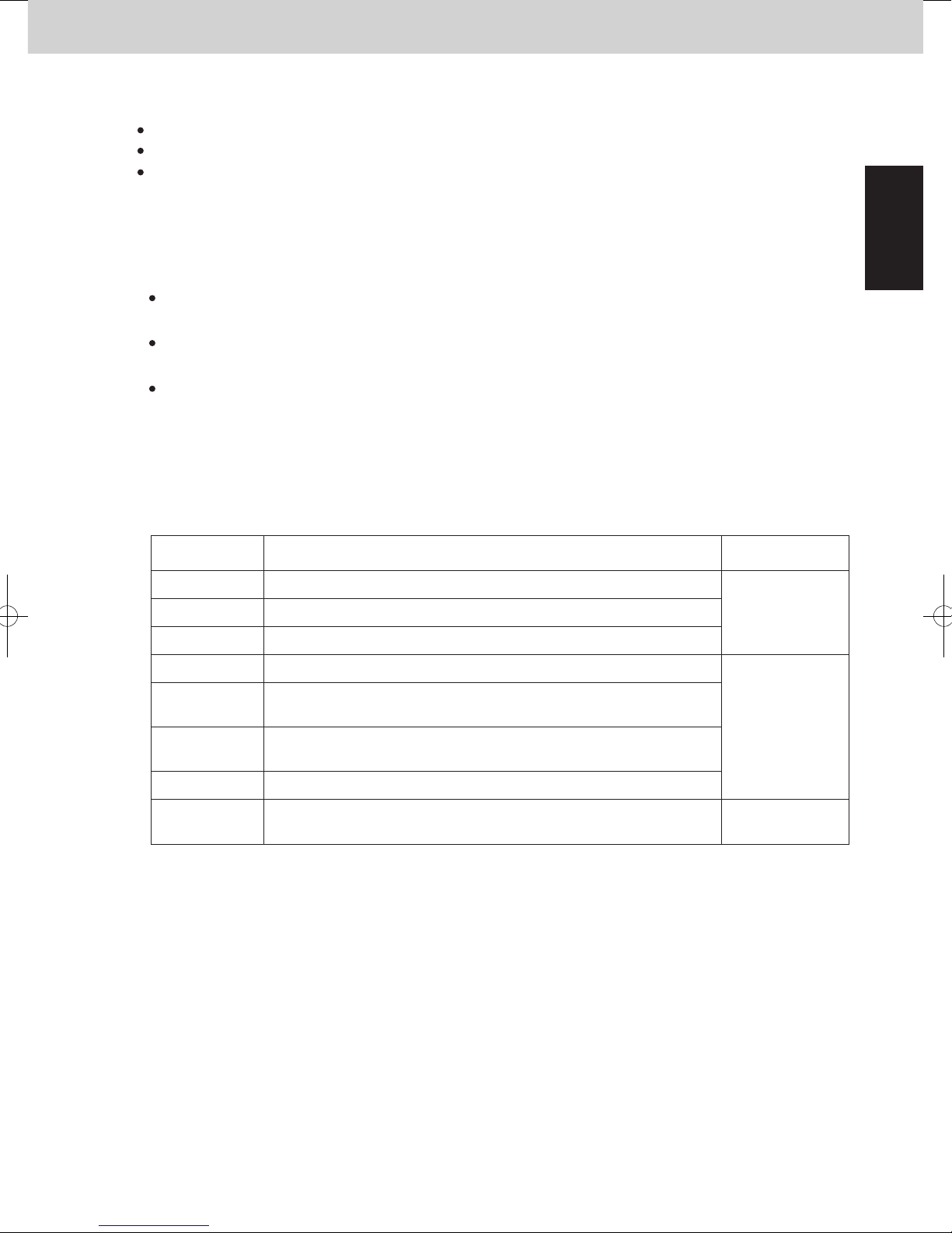
Mini VRF SYSTEM
Control Functions - Outdoor unit
1
5. Outdoor Unit CCU (command controller
unit) Control
2WAY VRF SYSTEM
Control Functions
6. Outdoor Unit CCU (command controller unit) Control
3-2. Heating mode
The indoor unit fan in heating mode is stopped from the CCU in the following condition.
Discharge air temperature of indoor unit ≤ 20°C
High pressure saturated temperature (HPT) in outdoor unit≤ 25°C
Liquid temperature (E1) in indoor unit ≤ 20°C
(4) Drain Pump Control
The CCU intervenes in drain pump control of the indoor
unit according to the setting in EEPROM in the outdoor unit.
The drain pump operates from the CCU control at the following condition.
DP counter ≥ 5
*The DP counter counts each oil recovery control, and 4-way Valve Adjustment Control in cooling operation.
Liquid temperature (E1) in the indoor unit which selected cooling mode < 0 °C
* Regardless of operating / stopped mode
Low Silhouette Ducted type indoor unit
In Low Silhouette Ducted types, dirt might be accumulated when water collects in the drain pan for a long
term.
Therefore, the drain pump works longer to drain water surely.
To activate this function, it is necessary to set EEPROM on the main outdoor unit PCB.
*
EEPROM setting in main outdoor unit
CODE: 0C
Setting No.
0
Invalid
Movement of drain pump
Indoor unit
operation mode
1
2
3
4
5
6
7 (Factory
preset mode)
*
When any of setting Nos. 4 – 7 is selected, this function works only for the type of F2, M1.
DP operates for 20 minutes and stops for 2 hours
DP operates for 20 minutes and stops for 20 minutes
DP always operates
DP operates for XX minutes when indoor unit's operation changes;
from thermostat ON → thermostat OFF or operation stopped.
DP operates for XX minutes when indoor unit's operation changes;
from thermostat ON or thermostat OFF → operation stopped.
Both Setting No. 4 and 5 functions.
DP operates for XX minutes when indoor unit's operation changes
from thermostat ON or thermostat OFF → operation stopped.
All mode
Cooling mode
Dry mode
Heating mode
Cooling mode
Dry mode
1 - 19
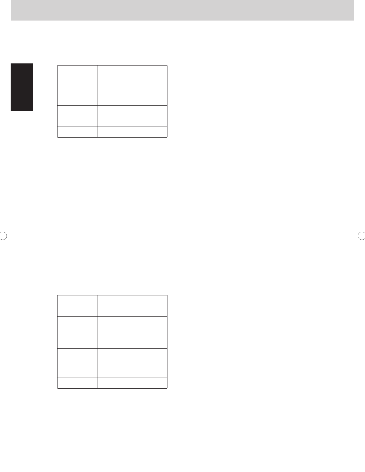
Mini VRF SYSTEM
Control Functions - Outdoor unit
1
5. Outdoor Unit CCU (command controller
unit) Control
6. Outdoor Unit CCU (command controller unit) Control
2WAY VRF SYSTEM
Control Functions
2WAY VRF SYSTEM
Control Functions
7. Oil Control
(1) Self-separator Oil Recovery Control
Oil is recovered from the oil separator to the compressor through the ORVR.
(2)
2-1.
System Oil Recovery Control
All indoor units MOV are opened for recovering oil from indoor side to compressor.
Start of system oil recovery control
Amount of oil in the compressor is presumed from operation condition. If presumed oil shortage, system oil
recovery control start.
This control is performed every 30 minutes - 5 hours.
For max 3 minutes
Indoor units
Control time
Outdoor units
MOV
RAP valve kit
Fan
All outdoor units operate at maximum horsepower.
MOV at all indoor units operate at a fixed pulse according to the indoor unit
capacity.
All indoor units operate in Cooling mode (OFF status).
Fan rotates at the set fan speed depending on the indoor unit operation mode
or at fan speed “LL”.
In the case of cooling mode
For 3 minutes
Indoor units
Control time
Outdoor units
MOV
RAP valve kit
Fan
All outdoor units operate at more than half horsepower.
MOV at all indoor units operate at 250 pulses.
All indoor units operate in Heating mode (ON status.)
Fan rotates at the set fan speed depending on the indoor unit operation mode
or at fan speed “LL”.
In the case of heating mode
2-2.
The system oil recovery control shall be performed as the flow mentioned below.
Normal operation → System oil recovery control → Normal operation
Simplified flow of system oil recovery control
*
Operating time “XX” under the section “(4) Drain Pump Control” described on previous page is able to set
(5) Discharge Air Temperature Control
in EEPROM of the main outdoor unit.
EEPROM setting in main outdoor unit
CODE: 2B
Setting No.
20
30
40
50 50 (minutes)
60
*
The drain pump always operates when the indoor unit is thermostat ON in cooling operation.
Once the drain pump operates, it keeps operating for 20 minutes.
*
In the above 2 cases, the drain pump operates by the signal of indoor PCB, not by the CCU.
For Type F2 and M1 indoor units, discharge air temperature is controlled from the CCU to prevent
dew condensation on duct surface in cooling operation.
It is able to use this function on cassette models but have to change the parameter in indoor unit.
The CCU monitors and adjusts ∆To of indoor unit.
The adjustment is made by compressor capacity and MOV operation in the indoor unit.
∆To : Cooling (Discharge air temperature) - (Preset discharge air temperature)
Heating (Preset discharge air temperature) - (Discharge air temperature)
(factory preset mode)
XX
20 (minutes)
30 (minutes)
40 (minutes)
60 (minutes)
Situation in which indoor unit thermostat OFF by discharge air temperature control
∆To ≤ - 3.5 degrees Celsius, and this condition continues for 7 minutes
∆To < - 2.0 degrees Celsius, and this condition continues for (20 + XX) minutes
*
The above mentioned “XX” is able to set in EEPROM of the main outdoor unit.
EEPROM setting in main outdoor unit
CODE: E1
Setting No.
*
Regarding the preset discharge air temperature that is set in the indoor unit is able to change,
see the section “5. REMOTE CONTROLLER FUNCTIONS” in this Service Manual.
-20
-19
-18
...
0
...
10
XX
-20 (minutes)
-19 (minutes)
-18 (minutes)
...
0 (minutes)
(factory preset mode)
...
10 (minutes)
1 - 20
 Loading...