

Panasonic U-8ME1E8, U-10ME1E8, U-12ME1E8 E, U-14ME1E8, U-16ME1E8 Installation Instructions Manual
...
EN
FR
INSTALLATION INSTRUCTIONS
INSTRUCTIONS D’INSTALLATION
EINBAUANLEITUNG
ISTRUZIONI DI INSTALLAZIONE
INSTRUÇÕES DE INSTALAÇÃO
ΟΔΗΓΙΕΣ ΕΓΚΑΤΑΣΤΑΣΗΣ
INSTRUCCIONES DE INSTALACIÓN
Outdoor Units
U-8ME1E8(E), U-10ME1E8(E), U-12ME1E8(E), U-14ME1E8(E), U-16ME1E8(E), U-18ME1E8(E), U-20ME1E8(E)
Unités extérieures
U-8ME1E8(E), U-10ME1E8(E), U-12ME1E8(E), U-14ME1E8(E), U-16ME1E8(E), U-18ME1E8(E), U-20ME1E8(E)
Außeneinheiten
U-8ME1E8(E), U-10ME1E8(E), U-12ME1E8(E), U-14ME1E8(E), U-16ME1E8(E), U-18ME1E8(E), U-20ME1E8(E)
Unità esterne
U-8ME1E8(E), U-10ME1E8(E), U-12ME1E8(E), U-14ME1E8(E), U-16ME1E8(E), U-18ME1E8(E), U-20ME1E8(E)
Unidades exteriores
U-8ME1E8(E), U-10ME1E8(E), U-12ME1E8(E), U-14ME1E8(E), U-16ME1E8(E), U-18ME1E8(E), U-20ME1E8(E)
Εξωτερικές Μονάδες
U-8ME1E8(E), U-10ME1E8(E), U-12ME1E8(E), U-14ME1E8(E), U-16ME1E8(E), U-18ME1E8(E), U-20ME1E8(E)
Unidades exteriores
U-8ME1E8(E), U-10ME1E8(E), U-12ME1E8(E), U-14ME1E8(E), U-16ME1E8(E), U-18ME1E8(E), U-20ME1E8(E)
– 2WAY System Air Conditioner –
for Refrigerant R410A
– Climatiseur Système 2 VOIES –
pour réfrigérant R410A
–
Klimaanlagen-System in ZWEIWEGE-AUSFÜHRUNG
für Kühlmittel R410A
– Condizionatore d’aria 2 VIE –
per refrigerante R410A
– Sistema de Ar Condicionado de 2 Vias –
para Refrigerante R410A
2 κατευθύνσεων κλιματικό σύστημα
–
για το Ψυκτικό μέσο R410A
–
Acondicionador de aire del sistema 2 SENTIDOS
para refrigerante R410A
–
–
–
DE
IT
PT
GR
ES
SUPPLEMENT
85464369333022 2010
INSTALLATION INSTRUCTIONS
– 2WAY System Air Conditioner –
for Refrigerant R410A
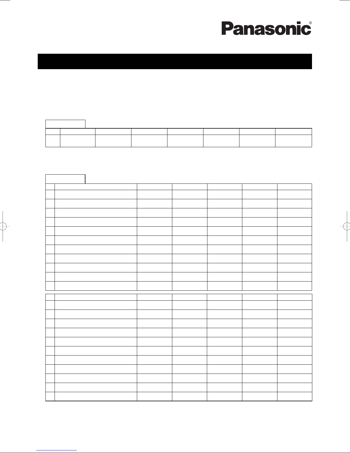
R410A Models
■
Model No.
Outdoor Units
Type 8hp 10hp 12hp 14hp 16hp 18hp 20hp
ME1
* Refrigerant R410A is used in the outdoor units.
* When the DIP switch (S011) on the outdoor unit PCB is set to the “ON” position, the unit changes to the high-COP mode.
** Outdoor unit model name ended with letters “E8E” is salt-air damage resistant specifi cations.
U-8ME1E8
U-8ME1E8E**
For details, refer to “9. INSTRUCTIONS FOR HIGH-COP MODE”.
Indoor Units
Indoor Unit Type 22 28 36 45 56
D1 1-Way Cassette S-28MD1E5 S-36MD1E5 S-45MD1E5 S-56MD1E5
L1 2-Way Cassette S-22ML1E5 S-28ML1E5 S-36ML1E5
U1 4-Way Cassette S-22MU1E5 S-28MU1E5 S-36MU1E5 S-45MU1E5 S-56MU1E5
Y1 4-Way Cassette 60 × 60 S-22MY1E5
K1 Wall-Mounted S-22MK1E5 S-28MK1E5 S-36MK1E5 S-45MK1E5 S-56MK1E5
T1 Ceiling
F1 Low Silhouette Ducted S-22MF1E5 S-28MF1E5 S-36MF1E5 S-45MF1E5 S-56MF1E5
M1 Slim Low Static Ducted S-22MM1E5 S-28MM1E5 S-36MM1E5 S-45MM1E5 S-56MM1E5
E1 High Static Pressure Ducted
P1 Floor Standing S-22MP1E5 S-28MP1E5 S-36MP1E5 S-45MP1E5 S-56MP1E5
R1 Concealed Floor Standing S-22MR1E5 S-28MR1E5 S-36MR1E5 S-45MR1E5 S-56MR1E5
U-10ME1E8
U-10ME1E8E**
U-12ME1E8
U-12ME1E8E**
U-14ME1E8
U-14ME1E8E**
S-28MY1E5 S-36MY1E5 S-45MY1E5 S-56MY1E5
U-16ME1E8
U-16ME1E8E**
S-36MT1E5 S-45MT1E5 S-56MT1E5
U-18ME1E8
U-18ME1E8E**
S-45ML1E5 S-56ML1E5
U-20ME1E8
U-20ME1E8E**
Indoor Unit Type 73 90 106 140 160
D1 1-Way Cassette S-73MD1E5
L1 2-Way Cassette S-73ML1E5
U1 4-Way Cassette S-73MU1E5 S-106MU1E5 S-140MU1E5 S-160MU1E5
Y1 4-Way Cassette 60 × 60
K1 Wall-Mounted S-73MK1E5 S-106MK1E5
T1 Ceiling S-73MT1E5 S-106MT1E5 S-140MT1E5
F1 Low Silhouette Ducted S-73MF1E5 S-90MF1E5 S-106MF1E5 S-140MF1E5 S-160MF1E5
M1 Slim Low Static Ducted
E1 High Static Pressure Ducted S-73ME1E5 S-106ME1E5 S-140ME1E5
P1 Floor Standing S-71MP1E5
R1 Concealed Floor Standing S-71MR1E5
* S-224ME1E5 and S-280ME1E5 are available.
IMPORTANT!
Please Read Before Starting
This air conditioning system meets strict safety and
operating standards. As the installer or service person,
it is an important part of your job to install or service the
system so it operates safely and efficiently.
For safe installation and trouble-free operation, you
must:
●
Carefully read this instruction booklet before beginning.
●
Follow each installation or repair step exactly as shown.
●
Observe all local, state, and national electrical codes.
●
This product is intended for professional use.
Permission from the power supplier is required when
installing the U-8ME1E8 (E) outdoor unit that is
connected to a 16 A distribution network.
●
This equipment complies with EN/IEC 61000-3-12
provided that the short-circuit power Ssc is greater than
or equals to the values corresponding to each model as
shown in the table below at the interface point between
the user’s supply and the public system.
It is the responsibility of the installer or user of the
equipment to ensure; by consultation with the distribution
network operator if necessary that the equipment is
connected only to supply with a short-circuit power Ssc
greater than or equals to the values corresponding to
each model as shown in the table below.
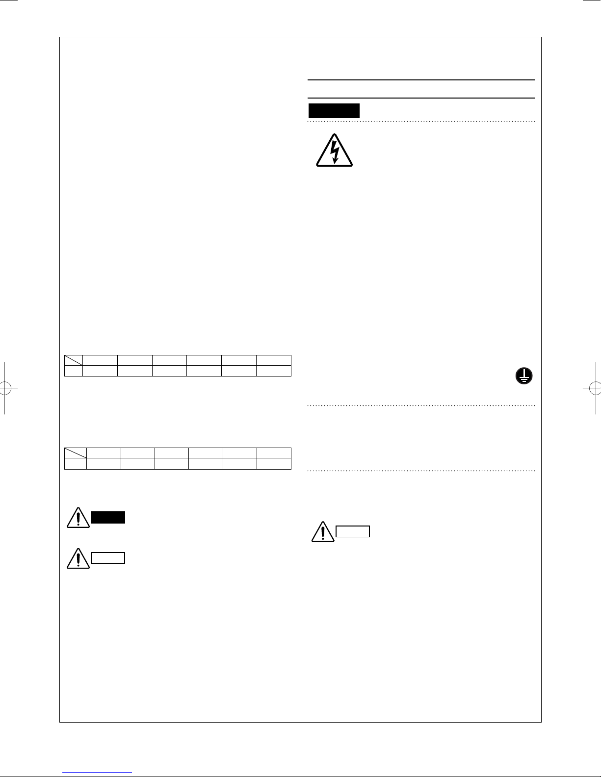
U-10ME1E8(E) U-12ME1E8(E) U-14ME1E8(E) U-16ME1E8(E) U-18ME1E8(E) U-20ME1E8(E)
Ssc
1,660 kW 1,660 kW 1,510 kW 1,510 kW 1,690 kW 1,690 kW
●
This equipment complies with EN/IEC 61000-3-11
provided that the system impedance Zmax is less than
or equal to the values corresponding to each model as
shown in the table below at the interface point between
the user’s supply and the public system. Consult with
the supply authority for the system impedance Zmax
U–10ME1E8(E) U–12ME1E8(E) U–14ME1E8(E) U–16ME1E8(E) U–18ME1E8(E)U–20ME1E8(E)
Zmax
0.194Ω 0.194Ω 0.194Ω 0.194Ω 0.194Ω 0.194Ω
●
Pay close attention to all warning and caution notices
given in this manual.
This symbol refers to a hazard or unsafe
WARNING
CAUTION
practice which can result in severe
personal injury or death.
This symbol refers to a hazard or
unsafe practice which can result in
personal injury or product or property
damage.
.
If Necessary, Get Help
These instructions are all you need for most installation
sites and maintenance conditions. If you require help for a
special problem, contact our sales/service outlet or your
certified dealer for additional instructions.
In Case of Improper Installation
The manufacturer shall in no way be responsible for
improper installation or maintenance service, including
failure to follow the instructions in this document.
SPECIAL PRECAUTIONS
WARNING
• Do not supply power to the unit until all wiring and tubing
are completed or reconnected and checked.
•
Highly dangerous electrical voltages are used in this system.
Carefully refer to the wiring diagram and these instructions
when wiring. Improper connections and inadequate
grounding can cause accidental injury or death.
• Ground the unit following local electrical codes.
•
Connect all wiring tightly. Loose wiring may cause
overheating at connection points and a possible fire hazard.
• Provide a power outlet to be used exclusively for each
unit, and a power supply disconnect, circuit breaker and
earth leakage breaker for overcurrent protection should
be provided in the exclusive line.
• Provide a power outlet exclusively for each unit, and
full disconnection means having a contact separation
in all poles must be incorporated in the fixed wiring in
accordance with the wiring rules.
• To prevent possible hazards from insulation failure,
the unit must be grounded.
When Transporting
Be careful when picking up and moving the indoor and
outdoor units. Get a partner to help, and bend your knees
when lifting to reduce strain on your back. Sharp edges or
thin aluminum fins on the air conditioner can cut your fingers.
When Installing…
…In a Room
Properly insulate any tubing run inside a room to prevent
“sweating” that can cause dripping and water damage to
walls and floors.
…In Moist or Uneven Locations
Use a raised concrete pad or concrete blocks to provide
a solid, level foundation for the outdoor unit. This prevents
water damage and abnormal vibration.
…In an Area with High Winds
Securely anchor the outdoor unit down with bolts and a
metal frame. Provide a suitable air baffle.
…In a Snowy Area (for Heat Pump-type Systems)
Install the outdoor unit on a raised platform that is higher
than drifting snow. Provide snow vents.
When Wiring
ELECTRICAL SHOCK CAN CAUSE
SEVERE PERSONAL INJURY OR DEATH.
ONLY A QUALIFIED, EXPERIENCED
ELECTRICIAN SHOULD ATTEMPT TO
WIRE THIS SYSTEM.
CAUTION
Keep the fire alarm and the air outlet
at least 1.5 m away from the unit.
2

When Connecting Refrigerant Tubing
Others
• When performing piping work do
not mix air except for specifIed
refrigerant (R410A) in refrigeration
cycle. It causes capacity down, and
WARNING
• Ventilate the room well, in the event that is refrigerant
gas leaks during the installation. Be careful not to allow
contact of the refrigerant gas with a flame as this will
cause the generation of poisonous gas.
• Keep all tubing runs as short as possible.
• Use the flare method for connecting tubing.
Apply refrigerant lubricant to the matching surfaces
•
of the flare and union tubes before connecting them,
then tighten the nut with a torque wrench for a leak-free
connection.
• Check carefully for leaks before starting the test run.
• Do not leak refrigerant while piping work for an
installation or re-installation, and while repairing
refrigeration parts.
Handle liquid refrigerant carefully as it may cause
frostbite.
risk of explosion and injury due to
high tension inside the refrigerant
cycle.
• Refrigerant gas leakage may cause
fire.
CAUTION
• Do not touch the air inlet or the
sharp aluminum fins of the
outdoor unit. You may hurt.
• Do not sit or step on the unit,
you may fall down accidentally.
• Do not stick any object into the
FAN CASE.
You may be injured and the
unit may be damaged.
When Servicing
• Turn the power OFF at the main power box
(mains) before opening the unit to check or repair
electrical parts and wiring.
• Keep your fingers and clothing away from any moving
parts.
• Clean up the site after you finish, remembering to
check that no metal scraps or bits of wiring have been
left inside the unit being serviced.
• Do not clean inside the indoor and
WARNING
CAUTION
outdoor units by users. Engage
authorized dealer or specialist for
cleaning.
• In case of malfunction of this
appliance, do not repair by yourself.
Contact to the sales dealer or service
dealer for a repair.
• Do not touch the air inlet or the
sharp aluminum fins of the
outdoor unit. You may get hurt.
•
Ventilate any enclosed areas when
installing or testing the refrigeration
system. Escaped refrigerant gas, on
contact with fire or heat, can produce
dangerously toxic gas.
•
Confirm after installation that no
refrigerant gas is leaking. If the gas
comes in contact with a burning stove,
gas water heater, electric room heater
or other heat source, it can cause the
generation of poisonous gas.
3
Check of Density Limit
The room in which the air conditioner is to be installed
requires a design that in the event of refrigerant gas
leaking out, its density will not exceed a set limit.
The refrigerant (R410A), which is used in the air conditioner,
is safe, without the toxicity or combustibility of ammonia, and
is not restricted by laws imposed to protect the ozone layer.
However, since it contains more than air, it poses the risk of
suffocation if its density should rise excessively. Suffocation
from leakage of refrigerant is almost non-existent. With the
recent increase in the number of high density buildings,
however, the installation of multi air conditioner systems is
on the increase because of the need for effective use of floor
space, individual control, energy conservation by curtailing heat
and carrying power, etc.
Most importantly, the multi air conditioner system is able
to replenish a large amount of refrigerant compared to
conventional individual air conditioners. If a single unit of the
multi air conditioner system is to be installed in a small room,
select a suitable model and installation procedure so that if the
refrigerant accidentally leaks out, its density does not reach the
limit (and in the event of an emergency, measures can be made
before injury can occur).
In a room where the density may exceed the limit, create an
opening with adjacent rooms, or install mechanical ventilation
combined with a gas leak detection device. The density is as
given below.
Total amount of refrigerant (kg)
Min. volume of the indoor unit installed room (m
< Density limit (kg/m
The density limit of refrigerant which is used in multi air
conditioners is 0.3 kg/m
3
(ISO 5149).
3
)
NOTE
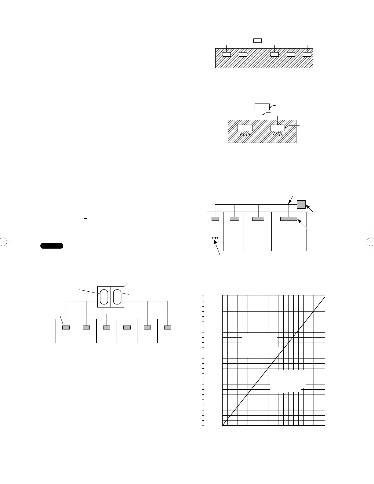
1. If there are 2 or more refrigerating systems in a single
refrigerating device, the amount of refrigerant should be as
charged in each independent device.
For the amount of charge in this example:
e.g., charged
amount (10 kg)
Indoor unit
Room A Room B Room C Room D Room E Room F
Outdoor unit
e.g., charged
amount (15 kg)
The possible amount of leaked refrigerant gas in rooms A,
B and C is 10 kg.
The possible amount of leaked refrigerant gas in rooms D,
E and F is 15 kg.
3
)
2. The standards for minimum room volume are as follows.
(1) No partition (shaded portion)
(2) When there is an effective opening with the adjacent room
for ventilation of leaking refrigerant gas (opening without
a door, or an opening 0.15% or larger than the respective
floor spaces at the top or bottom of the door).
Outdoor unit
Refrigerant tubing
Indoor unit
(3) If an indoor unit is installed in each partitioned room and
the refrigerant tubing is interconnected, the smallest room
of course becomes the object. But when mechanical
ventilation is installed interlocked with a gas leakage
detector in the smallest room where the density limit is
exceeded, the volume of the next smallest room becomes
the object.
Refrigerant tubing
Outdoor unit
Very
small
room
Small
room
Mechanical ventilation device – Gas leak detector
Medium
room
Large room
Indoor unit
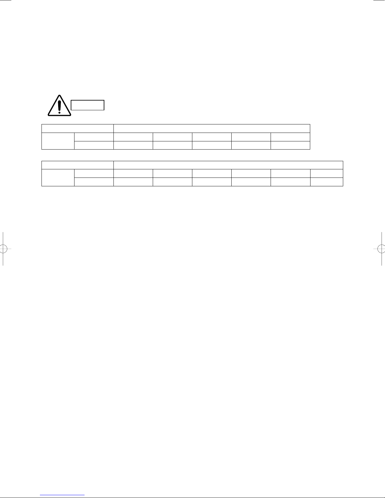
3. The minimum indoor floor space compared with the
amount of refrigerant is roughly as follows: (When the
ceiling is 2.7 m high)
3
2
m
m
337.5
125
324.0
120
310.5
115
297.0
110
283.5
105
100
270.0
95
256.0
90
243.0
85
229.5
80
216.0
75
202.5
70
189.0
65
175.5
60
162.0
55
148.5
50
135.0
Min. indoor volume
45
Min. indoor floor area
121.5
(when the ceiling is 2.7 m high)
40
108.0
35
94.5
30
81.0
25
67.5
20
54.0
40.5
15
10
27.0
5
13.5
0
0.0
Range below the
density limit of
0.3 kg/m³
(Countermeasures
not needed)
Range above the
density limit of 0.3
kg/m³
(Countermeasures
needed)
20100 3040 6070809010050
Total amount of refrigerant
kg
4
Precautions for Installation Using New Refrigerant
1. Care regarding tubing
1-1. Process tubing
● Material: Use C1220 phosphorous deoxidized copper specified in JIS H3300 “Copper and Copper Alloy Seamless Pipes and Tubes.”
For tubes of ø22.22 or larger, use C1220 T-1/2H material or H material, and do not bend the tubes.
● Tubing size: Be sure to use the sizes indicated in the table below.
● Use a tube cutter when cutting the tubing, and be sure to remove any flash. This also applies to distribution joints (optional).
● When bending tubing, use a bending radius that is 4 times the outer diameter of the tubing or larger.
Use sufficient care in handling the tubing. Seal the tubing ends with caps or tape to
CAUTION
Material O
Copper tube
Copper tube
1-2. Prevent impurities including water, dust and oxide from entering the tubing. Impurities can cause R410A refrigerant deterioration
and compressor defects. Due to the features of the refrigerant and refrigerating machine oil, the prevention of water and other
impurities becomes more important than ever.
Outer diameter 6.35 9.52 12.7 15.88 19.05
Wall thickness 0.8 0.8 0.8 1.0 1.2
Material 1/2 H, H
Outer diameter 22.22 25.4 28.58 31.75 38.1 41.28
Wall thickness 1.0 1.0 1.0 1.1 over 1.35 over 1.45
prevent dirt, moisture, or other foreign substances from entering. These substances
can result in system malfunction.
Unit: mm
Unit: mm
2. Be sure to recharge the refrigerant only in liquid form.
2-1. Since R410A is a non-azeotrope, recharging the refrigerant in gas form can lower performance and cause defects in the unit.
2-2. Since refrigerant composition changes and performance decreases when gas leaks, collect the remaining refrigerant and recharge
the required total amount of new refrigerant after fixing the leak.
5

3. Different tools required
3-1. Tool specifications have been changed due to the characteristics of R410A.
Some tools for R22- and R407C-type refrigerant systems cannot be used.
R407C tools
Item New tool?
compatible
Remarks
with R410A?
Manifold gauge Yes No Types of refrigerant, refrigerating machine oil,
and pressure gauge are different.
Charge hose Yes No To resist higher pressure, material must be
changed.
Vacuum pump Yes Yes Use a conventional vacuum pump if it is equipped
with a check valve. If it has no check valve,
purchase and attach a vacuum pump adapter.
Leak detector Yes No Leak detectors for CFC and HCFC that react to
chlorine do not function because R410A contains
no chlorine. Leak detectors for HFC134a can be
used for R410A.
Flaring oil Yes No For systems that use R22, apply mineral oil
(Suniso oil) to the flare nuts on the tubing to
prevent refrigerant leakage. For machines that
use R407C or R410A, apply synthetic oil (ether
oil) to the flare nuts.
* Using tools for R22 and R407C and new tools for R410A together can cause defects.
Manifold gauge
Vacuum pump
Outlet
Inlet
3-2. Use R410A exclusive cylinder only.
Single-outlet valve
(with siphon tube)
Liquid refrigerant should be
recharged with the cylinder
standing on end as shown.
Valve
Liquid
6

CONTENTS
Page Page
IMPORTANT! . . . . . . . . . . . . . . . . . . . . . . . . . . . . . . . . . . . . . . 2
Please Read Before Starting
Check of Density Limit
Precautions for Installation Using New Refrigerant
1. GENERAL . . . . . . . . . . . . . . . . . . . . . . . . . . . . . . . . . . . . . . 8
1-1. Tools Required for Installation (not supplied)
1-2. Accessories Supplied with Outdoor Unit
1-3. Type of Copper Tube and Insulation Material
1-4. Additional Materials Required for Installation
1-5. Tubing Length
1-6. Tubing Size
1-7. Straight Equivalent Length of Joints
1-8. Additional Refrigerant Charge
1-9. System Limitations
1-10. Check of Limit Density
1-11. Installing Distribution Joint
1-12. Optional Distribution Joint Kits
1-13. Example of Tubing Size Selection and Refrigerant
Charge Amount
2. SELECTING THE INSTALLATION SITE . . . . . . . . . . . . . 18
2-1. Outdoor Unit
2-2. Shield for Horizontal Exhaust Discharge
2-3. Installing the Outdoor Unit in Heavy Snow Areas
2-4. Precautions When Installing in Heavy Snow Areas
2-5. Dimensions of Wind Ducting
2-6. Dimensions of Snow Ducting
6. AIR PURGING . . . . . . . . . . . . . . . . . . . . . . . . . . . . . . . . . . 36
Air Purging with a Vacuum Pump (for Test Run) Preparation
■
7. TEST RUN . . . . . . . . . . . . . . . . . . . . . . . . . . . . . . . . . . . . 39
7-1. Preparing for Test Run
7-2. Test Run Procedure
7-3. Main Outdoor Unit PCB Setting
7-4. Auto Address Setting
7-5. Remote Controller Test Run Settings
7-6. Caution for Pump Down
7-7. Meaning of Alarm Messages
8. MARKINGS FOR DIRECTIVE
97/23/EC (PED) . . . . . . . . . . . . . . . . . . . . . . . . . . . . . . . . . 55
9. INSTRUCTIONS FOR HIGH-COP MODE . . . . . . . . . . . . 56
3. HOW TO INSTALL THE OUTDOOR UNIT . . . . . . . . . . . . 20
3-1. Transporting
3-2. Installing the Outdoor Unit
3-3. Routing the Tubing
3-4. Prepare the Tubing
3-5. Connect the Tubing
4. ELECTRICAL WIRING . . . . . . . . . . . . . . . . . . . . . . . . . . . 26
4-1. General Precautions on Wiring
4-2. Recommended Wire Length and Wire Diameter for
Power Supply System
4-3. Wiring System Diagram
5. HOW TO PROCESS TUBING . . . . . . . . . . . . . . . . . . . . . 31
5-1. Connecting the Refrigerant Tubing
5-2. Connecting Tubing Between Indoor and Outdoor
Units
5-3. Insulating the Refrigerant Tubing
5-4. Taping the Tubes
5-5. Finishing the Installation
7
1. GENERAL
This booklet briefly outlines where and how to install the air conditioning system. Please read over the entire set of instructions for the
outdoor unit and make sure all accessory parts listed are with the system before beginning.
1-1. Tools Required for Installation (not supplied)
1. Flathead screwdriver
2. Phillips head screwdriver
3. Knife or wire stripper
4. Tape measure
5. Carpenter’s level
6. Sabre saw or key hole saw
7. Hacksaw
8. Core bits
9. Hammer
10. Drill
11. Tube cutter
12. Tube flaring tool
13. Torque wrench
14. Adjustable wrench
15. Reamer (for deburring)
16. Hexagonal wrench (4 mm and 5 mm)
17. Pliers
18. Cutting pliers
1-2. Accessories Supplied with Outdoor Unit
See Table 1-1.
1-3. Type of Copper Tube and Insulation Material
If you wish to purchase these materials separately from a local
source, you will need:
1. Deoxidized annealed copper tube for refrigerant tubing.
2. Foamed polyethylene insulation for copper tubes as
required to precise length of tubing. Refer to
“5-3. Insulating the Refrigerant Tubing” for details.
3. Use insulated copper wire for field wiring. Wire size varies
with the total length of wiring.
Refer to “4. Electrical Wiring” for details.
Check local electrical codes and
CAUTION
regulations before obtaining
wire. Also, check any specified
instructions or limitations.
1-4. Additional Materials Required for Installation
1. Refrigeration (armored) tape
2. Insulated staples or clamps for connecting wire
(See your local codes.)
3. Putty
4. Refrigeration tubing lubricant
5. Clamps or saddles to secure refrigerant tubing
6. Scale for weighing
Table 1-1 Outdoor Unit Unit: mm
Part Name Figure
Outer diameter
ø28.58
Connection
tubing
Inner diameter
ø25.4
8 hp 10 hp 12 hp 14 hp 16 hp 18 hp 20 hp
0000100
Q’ty
8
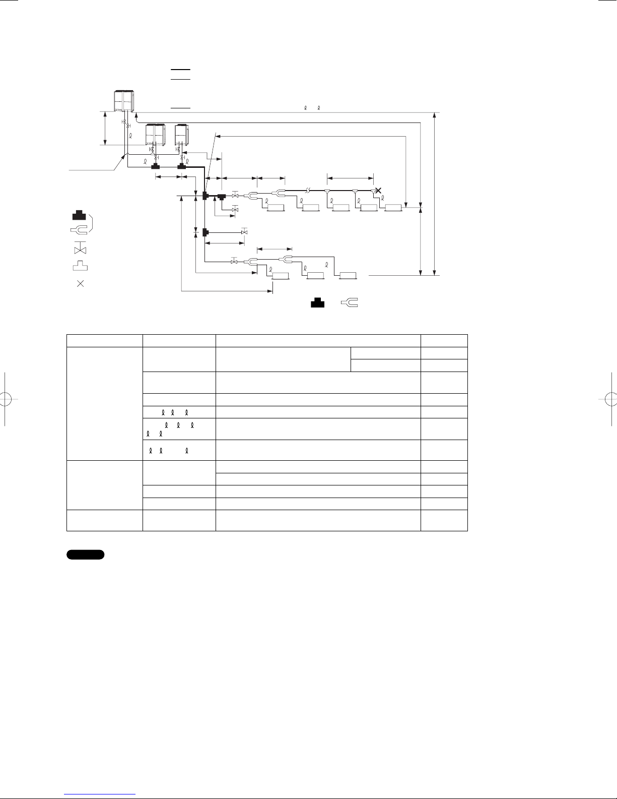
1-5. Tubing Length
Select the installation location so that the length and size of refrigerant tubing are within the allowable range shown in the figure below.
1. Main tubing length LM = LA + LB …
2.
Main distribution tubes LC – LH are selected according to the capacity after the distribution joint.
3. The outdoor connection main tubing (LO portion) is determined by the total capacity of the outdoor units that are connected to the
tube ends.
Sizes of indoor unit connection tubing 1 – 64 are determined by the connection tubing sizes on the indoor units.
4.
L1
H3
Balance tubing
(ø6.35)
Explanation of symbols
Distribution joint
(APR: purchased
separately)
Ball valve (field supply)
T-joint (field supply)
Solidly welded shut
(pinch weld)
Note: Do not use commercially available T-joints for the liquid tubing
* Be sure to use special R410A distribution joints (purchased separately) for outdoor unit connections and tubing branches.
C
LM
AB
LO
LA
LF
LB LC
Max. 40cm
Max. 40cm
LG
L4
LD L3
4
For
extension
For
extension
LH
1
L2
5
3
2
and parts.
R410A distribution joint
CZ-P680PJ2 (for outdoor unit)
CZ-P1350PJ2 (for outdoor unit)
CZ-P160BK2 (for indoor unit)
H1
62
64
63
CZ-P680BK2 (for indoor unit)
CZ-P1350BK2 (for indoor unit)
H2
Table 1-2 Ranges that Apply to Refrigerant Tubing Lengths and to Differences in Installation Heights
Item Mark Contents Length (m)
≤
≤
≤
≤
≤
≤
≤
≤
≤
≤
≤
180
200
50 *
3
30
1000
10
50
40
15 *
4
2
5
6
Allowable tubing
length
Allowable elevation
difference
Allowable length of
joint tubing
L = Length, H = Height
L1 Max. tubing length
∆
L (L2 – L4)
Difference between max. length and min.
length from the No.1 distribution joint
Actual length
Equivalent length
LM Max. length of main tubing (at max. diameter) *
1, 2... 64 Max. length of each distribution tube
L1+
1+ 2... 63+
A+ B+LF+LG+LH
A, B+LO, C+LO
H1
Total max. tubing length including length of
each distribution tube (only liquid tubing)
Maximum tubing length from outdoor’s 1st distribution
joint to each outdoor unit
When outdoor unit is installed higher than indoor unit
When outdoor unit is installed lower than indoor unit
H2 Max. difference between indoor units
H3 Max. difference between outdoor units
L3
T-joint tubing (field-supply); Max. tubing length between
the first T-joint and solidly welded-shut end point
NOTE
1: The outdoor connection main tubing (LO portion) is determined by the total capacity of the outdoor units that are connected to the
tube ends.
2: If the longest tubing length (L1) exceeds 90 m (equivalent length), increase the sizes of the main tubes (LM) by 1 rank for gas tubes
and liquid tubes. (Use a field supply reducer.) (Select the tube size from the table of main tube sizes (Table 1-3) on the following
page (LA table), and from the table of refrigerant tubing sizes (Table 1-8) on the second following page.)
3: If the longest main tube length (LM) exceeds 50 m, increase the main tube size at the portion before 50 m by 1 rank for the gas
tubes. (Use a field supply reducer.) Determine the length less than the limitation of allowable maximum tubing length.
(For the portion that exceeds 50 m, set based on the main tube sizes (LA) listed in the table on the following page.)
4: If the size of the existing tubing is already larger than the standard tubing size, it is not necessary to further increase the size.
* If the existing tubing is used, and the amount of on-site refrigerant charge exceeds the value listed below, then change the size of
the tubing to reduce the amount of refrigerant.
Total amount of refrigerant for the system with 1 outdoor unit: 50 kg
Total amount of refrigerant for the system with 2 outdoor units: 80 kg
Total amount of refrigerant for the system with 3 outdoor units: 100 kg
5: When the tubing length exceeds 40m, increase a longer liquid or gas tubing by 1 rank.
Refer to the Technical Data for the details.
6: If the tubing length exceeds 500m, the formula is 15 x (2 - all tubing length/500). Determine the length less than the limitation of
allowable maximum tubing length.
9

1-6. Tubing Size
Table 1-3 Main Tubing Size (LA)
kW 22.4 28.0 33.5 40.0 45.0 50.0 56.0 61.5 68.0 73.0 78.5 85.0 90.0 96.0
Total system
horsepower
Combined
outdoor units
Gas tubing (mm)
Liquid tubing (mm) ø9.52 ø12.7 ø15.88 ø19.05
kW 101.0 107.0 113.0 118.0 124.0 130.0 135.0 140.0 145.0 151.0 156.0 162.0 168.0
Total system
horsepower
Combined
outdoor units
Gas tubing (mm)
Liquid tubing (mm) ø19.05
*1: If future extension is planned, select the tubing diameter based on the total horsepower after extension.
However extension is not possible if the resulting tubing size is two ranks higher.
*2: The balance tube (outdoor unit tube) diameter is ø6.35.
*3: The refrigerant tubing should be used with R410A refrigerant.
*4: If the length of the longest tube (L1) exceeds 90 m (equivalent length), increase the main tube (LM) size by 1 rank for the
gas and liquid tubes. (Use field-supply reducers.) (Select from Table 1-3 and Table 1-8.)
*5: If the longest main tube length (LM) exceeds 50 m, increase the main tube size at the portion before 50 m by 1 rank for the
gas tubes.
(For the portion that exceeds 50 m, set based on the main tube sizes (LA) listed in the table above.)
8 10121416182022242628303234
8 101214161820
ø19.05 ø22.22
ø25.4 ø28.58 ø31.75
14 814 1014 1216 1216 1416 1618
36 38 40 42 44 46 48 50 52 54 56 58 60
16
16
16
16
18
20
20
20
20
20
16
20
18
20
20
14
12
16
12
16
14
16
16
16
16
16
16
18
16
18
18
20
18
20
20
20
ø38.10
Unit: mm
16
Size of tubing (LO) between outdoor units
■
Select the size of tubing between outdoor units based on the main tubing size (LA) as given in the table above.
Table 1-4 Main Tubing Size After Distribution (LB, LC...)
Total capacity
after distribution
Tubing size
Below kW
7.1
(2.5 hp)
Over kW –
Gas tubing (mm) ø12.7 ø15.88 ø19.05 ø22.22 ø25.4 ø28.58 ø28.58 ø31.75 ø38.1
Liquid tubing (mm)
ø9.52 ø9.52 ø9.52 ø9.52 ø12.7 ø12.7 ø15.88 ø19.05 ø19.05
16.0
(6 hp)
7.1
(2.5 hp)
22.5
(8.1 hp)
16.0
(6 hp)
30.0
(11 hp)
22.5
(8.1 hp)
42.0
(15 hp)
30.0
(11 hp)
52.4
(19 hp)
42.0
(15 hp)
70.0
(25 hp)
52.4
(19 hp)
98.0
(35 hp)
70.0
(25 hp)
Unit: mm
hp = horsepower
–
98.0
(35 hp)
Note: In case the total capacity of connected indoor units exceeds the total capacity of the outdoor units, select the main tubing size for
the total capacity of the outdoor units. (Especially the main tubing segments of LA, LB and LF.)
Table 1-5 Outdoor Unit Tubing Connection Size(
A – C)
Unit: mm
kW 22.4 28.0 33.5 40.0 45.0 50.0 56.0
Gas tubing
Liquid tubing
Balance tubing
ø19.05 ø22.22 ø25.4 ø28.58
Brazing connection
ø9.52 ø12.7 ø15.88
Flare connection
ø6.35
Flare connection
Gas tube
Balance tube Liquid tube
Table 1-6 Indoor Unit Tubing Connection Size
Indoor unit type 22 28 36 45 56 73 90 106 140 160 224 280
Gas tubing (mm) ø12.7 ø15.88 ø19.05 ø22.22
Liquid tubing (mm) ø6.35 ø9.52
Note: Use C1220T-1/2H or -H material for tubing over ø22.22.
10
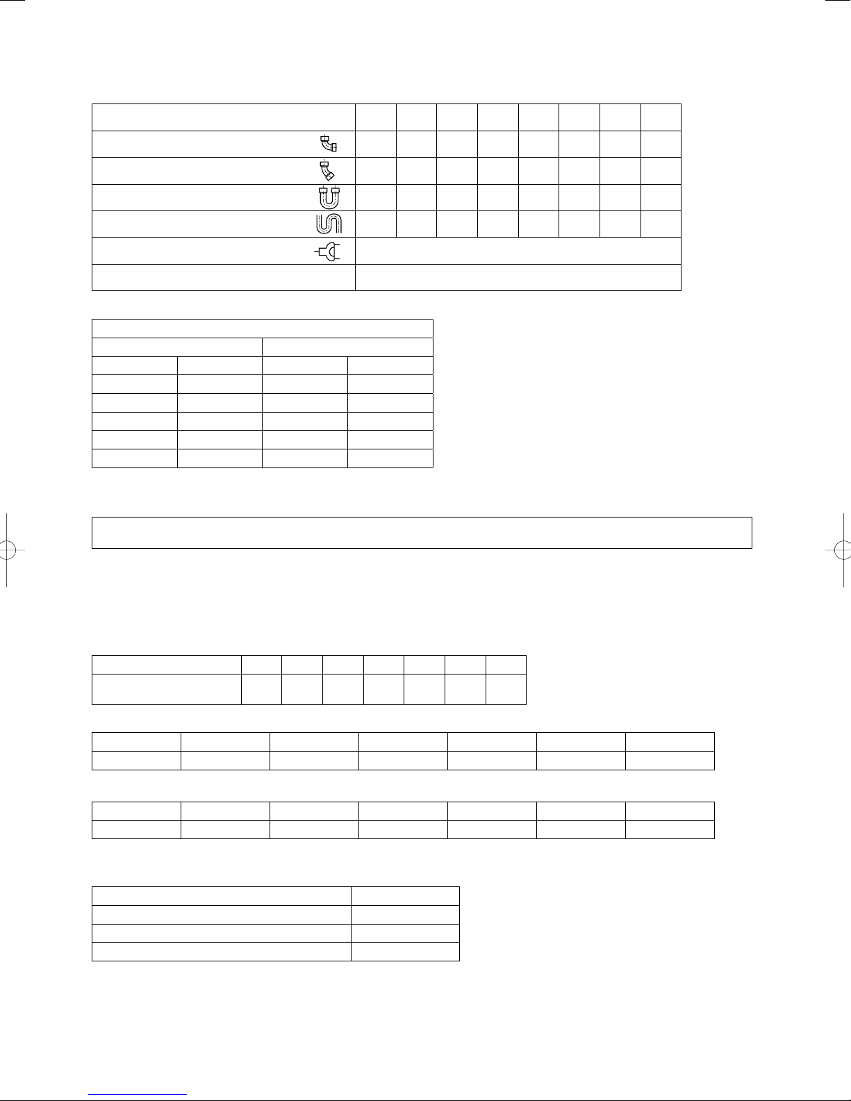
1-7. Straight Equivalent Length of Joints
Design the tubing system by referring to the following table for the straight equivalent length of joints.
Table 1-7 Straight Equivalent Length of Joints
Gas tubing size (mm) 12.7 15.88 19.05 22.22 25.4 28.58 31.8 38.1
90° elbow 0.30 0.35 0.42 0.48 0.52 0.57 0.70 0.79
45° elbow 0.23 0.26 0.32 0.36 0.39 0.43 0.53 0.59
U-shape tube bent (R60-100 mm) 0.90 1.05 1.26 1.44 1.56 1.71 2.10 2.37
Trap bend 2.30 2.80 3.20 3.80 4.30 4.70 5.00 5.80
Y-branch distribution joint Equivalent length conversion not needed.
Ball valve for service Equivalent length conversion not needed.
Table 1-8 Refrigerant tubing (Existing tubing can be used.)
Tubing size (mm)
Material O Material 1/2H • H
ø6.35 t0.8 ø22.22 t1.0
ø9.52 t0.8 ø25.4 t1.0
ø12.7 t0.8 ø28.58 t1.0
ø15.88 t1.0 ø31.75 t1.1
ø19.05 t1.2 ø38.1 over t1.35
ø41.28 over t1.45
* When bending the tubes, use a bending
radius that is at least 4 times the outer
diameter of the tubes.
In addition, take sufficient care to avoid
crushing or damaging the tubes when
bending them.
1-8. Additional Refrigerant Charge
Additional refrigerant charge amount is calculated below.
Required amount of additional refrigerant charge = [ (Amount of additional refrigerant charge per meter of each size of liquid tube x
its tube length) + (...) + (...)] + [(Necessary amount of additional refrigerant charge per outdoor unit) + (...) + (...)]
*Always charge accurately using a scale for weighing.
* If the existing tubing is used and the amount of on-site refrigerant charge exceeds the value listed below, change the size of the tubing
to reduce the amount of refrigerant.
Total amount of refrigerant for the system with 1 outdoor unit: 50 kg
Total amount of refrigerant for the system with 2 outdoor units: 80 kg
Total amount of refrigerant for the system with 3 outdoor units: 100 kg
Table 1-9-1 Amount of Additional Refrigerant Charge Per Meter, According to Liquid Tubing Size
Liquid tubing size 6.35 9.52 12.7 15.88 19.05 22.22 25.4
Amount of additional
refrigerant charge/m (g/m)
26 56 128 185 259 366 490
Table 1-9-2 Necessary Amount of Additional Refrigerant Charge Per Outdoor Unit
U-8ME1E8(E) U-10ME1E8(E) U-12ME1E8(E) U-14ME1E8(E) U-16ME1E8(E) U-18ME1E8(E) U-20ME1E8(E)
2.5 kg 3.5 kg 3.5 kg 6.4 kg 6.4 kg 7.6 kg 7.6 kg
Table 1-10 Refrigerant Charge Amount at Shipment (for Outdoor Unit)
U-8ME1E8(E) U-10ME1E8(E) U-12ME1E8(E) U-14ME1E8(E) U-16ME1E8(E) U-18ME1E8(E) U-20ME1E8(E)
9.9 kg 9.9 kg 9.9 kg 9.9 kg 9.9 kg 9.9 kg 9.9 kg
1-9. System Limitations
Table 1-11 System Limitations
Max. No. allowable connected outdoor units 3 *
Max. capacity allowable connected outdoor units 168 kW (60 hp)
Max. connectable indoor units 64 *
Max. allowable indoor/outdoor capacity ratio 50 – 200 % *
*1: In the case of 22 hp (type 61.5 kW) or smaller units, the number is limited by the total capacity of the connected indoor units.
*2: Up to 3 units can be connected if the system has been extended.
*3: It is strongly recommended that you choose the unit so the load can become between 50 and 130%.
2
1
3
11

WARNING
limit for the room in which the
unit is installed.
1-10. Check of Limit Density
Always check the gas density
When installing an air conditioner in a room, it is necessary to
ensure that even if the refrigerant gas accidentally leaks out, its
density does not exceed the limit level for that room.
If the density could exceed the limit level, it is necessary to
provide an opening between the unit and the adjacent room, or
to install mechanical ventilation which is interlocked with a leak
detector.
(Total refrigerant charged amount: kg)
(Min. indoor volume where the indoor unit is installed: m³)
≤ Limit density 0.3 (kg/m³)
The limit density of refrigerant R410A which is used in this unit
is 0.3 kg/m³ (ISO 5149).
The shipped outdoor unit comes charged with the amount of
refrigerant fi xed for each type, so add it to the amount that
is charged in the fi eld. (For the refrigerant charge amount at
shipment, refer to the unit’s nameplate.)
Minimum indoor volume & fl oor area as against the amount of
refrigerant is roughly as given in the following table.
3
2
m
m
337.5
125
324.0
120
310.5
115
297.0
110
283.5
105
100
270.0
95
256.0
90
243.0
85
229.5
80
216.0
75
202.5
70
189.0
65
175.5
60
162.0
55
148.5
50
135.0
Min. indoor volume
45
Min. indoor floor area
121.5
(when the ceiling is 2.7 m high)
40
108.0
35
94.5
30
81.0
25
67.5
20
54.0
40.5
15
10
27.0
5
13.5
0
0.0
Range below the
density limit of
0.3 kg/m³
(Countermeasures
not needed)
Range above the
density limit of 0.3
kg/m³
(Countermeasures
needed)
20100 3040 6070809010050
Total amount of refrigerant
Pay special attention to any
location, such as a basement,
CAUTION
etc., where leaking refrigerant
can accumulate, since refrigerant
gas is heavier than air.
1-11. Installing Distribution Joint
(1) Refer to “HOW TO ATTACH DISTRIBUTION JOINT”
enclosed with the optional distribution joint kit
(CZ-P680PJ2, CZ-P1350PJ2, CZ-P160BK2, CZ-P680BK2,
CZ-P1350BK2).
(2) When creating a branch using a commercially available
T-joint (header joint system), orient the main tubing so that
it is either horizontal (level) or vertical. In order to prevent
accumulation of refrigerant oil in stopped units, if the main
tubing is horizontal then each branch tubing length should be
at an angle that is greater than horizontal. If the main tubing
is vertical, provide a raised starting portion for each branch.
[Header joint system]
● Be sure to solidly weld shut the T-joint end (marked by “X” in
the figure). In addition, pay attention to the insertion depth of
each connected tube so that the flow of refrigerant within the
T-joint is not impeded.
● When using the header joint system, do not make further
branches in the tubing.
● Do not use the header joint system on the outdoor unit side.
(3) If there are height differences between indoor units or if
branch tubing that follows a distribution joint is connected
to only 1 unit, a trap or ball valve must be added to that
distribution joint. (When adding the ball valve, locate it within
40 cm of the distribution joint.)
If a trap or ball valve is not added, do not operate the
system before repairs to a malfunctioning unit are
completed. (The refrigerant oil sent through the tubing
to the malfunctioning unit will accumulate and may
damage the compressor.)
°
15 to 30
B
B
Header joint system (Indoor)
Outdoor
Indoor
Horizontal
line
L3< 2 m
Horizontal
A
line
Arrow view
Install at a
positive angle
Indoor
Indoor
Horizontal
line
A
View as seen
from arrow
Install at a
positive angle
(15 – 30°)
Solidly welded
shut (X)
Types of vertical trap specifications
(When using ball valve)
Main tubing
Ball valve
kg
(BV: purchased
separately)
Indoor unit (1)
Main tubing
Indoor unit is directed downward
(When not using ball valve)
Indoor unit (more than 2 units)
(If only 1 unit is connected, a ball valve
is also needed on this side.)
Branch tubing is
directed upward.
More than
20 cm
Horizontal
Indoor unit
(Each unit is connected
to tubing that is either
level or is directed
downward.)
12
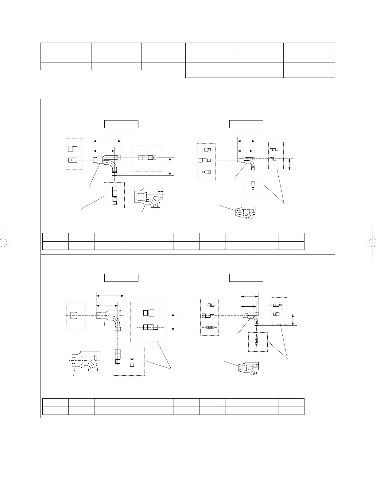
1-12. Optional Distribution Joint Kits
See the installation instructions packaged with the distribution joint kit for the installation procedure.
Table 1-12
Model name
1. CZ-P680PJ2 68.0 kW or less For outdoor unit 3. CZ-P160BK2 22.4 kW or less For indoor unit
2. CZ-P1350PJ2 168.0 kW or less For outdoor unit 4. CZ-P680BK2 68.0 kW or less For indoor unit
Tubing size (with thermal insulation)
■
Cooling capacity
after distribution
Remarks Model name
5. CZ-P1350BK2 168.0 kW or less For indoor unit
Cooling capacity
after distribution
Remarks
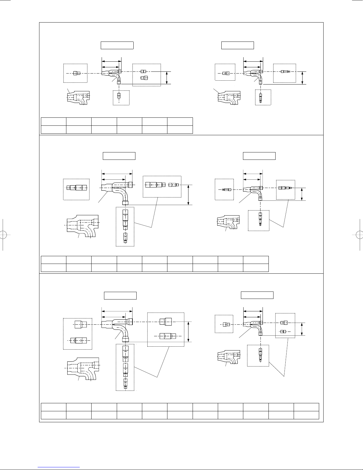
1. CZ-P680PJ2
For outdoor unit (Capacity after distribution joint is 68.0 kW or less.)
Example:
Gas tubing
Liquid tubing
B
D
Distribution Joint
Reducing Joints
135
175
C
DCEF
114
C
Insulation
F
EF
I
H
Insulation
Distribution
Joint
110
97
HFI
G
G
G
H
I
Reducing
Joints
Table 1-13 Size of connection point on each part (Shown are inside diameters of tubing)
Size Part A Part B Part C Part D Part E Part F Part G Part H Part I
mm ø38.1 ø31.75 ø28.58 ø25.4 ø22.22 ø19.05 ø15.88 ø12.7 ø9.52
2. CZ-P1350PJ2
For outdoor unit (Capacity after distribution joint is greater than 68.0 kW and no more than 168.0 kW.)
Example:
A
Insulation
B
Distribution
Joint
Gas tubing
175
135
Liquid tubing
110
B
A
114
C
D
B
C
E
D
F
Reducing
Joints
F
EF
I
H
Insulation
Distribution
Joint
97
G
HFI
G
G
H
I
Reducing
Joints
Table 1-14 Size of connection point on each part (Shown are inside diameters of tubing)
Size Part A Part B Part C Part D Part E Part F Part G Part H Part I
mm ø38.1 ø31.75 ø28.58 ø25.4 ø22.22 ø19.05 ø15.88 ø12.7 ø9.52
72
Unit: mm
72
Unit: mm
13
3. CZ-P160BK2
Use: For indoor unit (Capacity after distribution joint is 22.4 kW or less.)
Example:
Gas tubing
Liquid tubing
Insulation
A
B
Distribution
Joint
110
97
C
B
B
A
72
Insulation
D
Distribution
Joint
110
97
C
C
Table 1-15 Size of connection point on each part (Shown are inside diameters of tubing)
Size Part A Part B Part C Part D Part E
mm ø19.05 ø15.88 ø12.7 ø9.52 ø6.35
4. CZ-P680BK2
Use: For indoor unit (Capacity after distribution joint is greater than 22.4 kW and no more than 68.0 kW.)
Example:
D
C
B
Distribution
Joint
A
Gas tubing
175
135
A
Liquid tubing
110
97
A
C
B
F
D
114
E
G
E
F
Distribution
Joint
B
C
Insulation
D
E
F
Reducing
Joints
Insulation
Table 1-16 Size of connection point on each part (Shown are inside diameters of tubing)
Size Part A Part B Part C Part D Part E Part F Part G Part H
mm ø28.58 ø25.4 ø22.22 ø19.05 ø15.88 ø12.7 ø9.52 ø6.35
C
D
72
E
C
D
E
Unit: mm
E
G
F
72
H
E
F
G
H
Reducing
Joints
Unit: mm
5. CZ-P1350BK2
Use: For indoor unit (Capacity after distribution joint is greater than 68.0 kW and no more than 168.0 kW.)
Example:
A
D
C
Insulation
Gas tubing
135
B
Distribution
Joint
175
A
B
C
114
D
B
F
Distribution
Joint
C
D
E
F
G
H
Reducing
Joints
Insulation
Liquid tubing
110
97
G
F
G
H
72
G
H
I
J
Reducing
Joints
Unit: mm
Table 1-17 Size of connection point on each part (Shown are inside diameters of tubing)
Size Part A Part B Part C Part D Part E Part F Part G Part H Part I Part J
mm ø38.1 ø31.75 ø28.58 ø25.4 ø22.22 ø19.05 ø15.88 ø12.7 ø9.52 ø6.35
14

1-13. Example of Tubing Size Selection and Refrigerant Charge Amount
Additional refrigerant charging
Based on the values in Tables 1-3, -4, -5, -6, 9-1 and 9-2, use the liquid tubing size and length, and calculate the amount of additional
refrigerant charge using the formula below.
Required additional
refrigerant charge (kg)
(a) : Liquid tubing Total length of ø22.22 (m) (d) : Liquid tubing Total length of ø12.7 (m)
(b) : Liquid tubing Total length of ø19.05 (m) (e) : Liquid tubing Total length of ø9.52 (m)
(c) : Liquid tubing Total length of ø15.88 (m) (f) : Liquid tubing Total length of ø6.35 (m)
● Charging procedure
Be sure to charge with R410A refrigerant in liquid form.
1. After performing a vacuum, charge with refrigerant from the liquid tubing side. At this time, all valves must be in the “fully closed”
position.
2. If it was not possible to charge the designated amount, operate the system in Cooling mode while charging with refrigerant from
the gas tubing side. (This is performed at the time of the test run. For this, all valves must be in the “fully open” position. However
if only one outdoor unit is installed, a balance tube is not used. Therefore, leave the valves fully closed.)
Charge with R410A refrigerant in liquid form.
With R410A refrigerant, charge while adjusting the amount being fed a little at a time in order to prevent liquid refrigerant from
backing up.
● After charging is completed, turn all valves to the “fully open” position.
● Replace the tubing covers as they were before.
CAUTION
=[366 ×(a) + 259 ×(b) + 185 ×(c) + 128 ×(d) + 56 ×(e) + 26 ×(f)] ×10–3 + Necessary amount of
additional refrigerant charge per outdoor unit.
1. R410A additional charging absolutely must be done through liquid charging.
2. The R410A refrigerant cylinder has a gray base color, and the top part is pink.
3. The R410A refrigerant cylinder includes a siphon tube. Check that the siphon tube is present.
(This is indicated on the label at the top of the cylinder.)
4. Due to differences in the refrigerant, pressure, and refrigerant oil involved in installation, it is
not possible in some cases to use the same tools for R22 and for R410A.
Balance tube
Use a flathead screwdriver and
open by turning the part with the
screw groove to the right, from
“–” to “|”.
Liquid tube
Use a Hexagonal wrench and turn
to the left to open.
Hexagonal wrench width : 8 ~ 16 hp types 4 mm
Gas tube
8 hp type :
Use a flathead screwdriver and open by turning the part
with the screw groove to the left, from “–” to “|”.
10 ~ 20 hp types :
Use pliers and turn 90 degrees to the left and open.
18 ~ 20 hp types 5 mm
Turn 90 degrees to the left.
Fully closed (at shipment) Fully open
How to turn the tub
(10 ~ 20 hp types)
15

Example:
Outdoor unit
12 hp
type
● Example of each tubing length
14 hp
type
C
B
16 hp
type
LO
A
LA
LB
1 2 3 4 5 6 7
160 type 106 type 140 type 160 type 160 type 73 type 140 type
LC
LD
LE
LF
Main tubing Distribution joint tubing
LO = 2 m LD = 15 m Outdoor side Indoor side
LA = 40 m LE = 10 m
LB = 5 m LF = 10 m
LC = 5 m
A = 2 m 1 = 30 m 5 = 2 m
B = 2 m 2 = 5 m 6 = 6 m
C = 3 m 3 = 5 m 7 = 5 m
4 = 5 m
Note :The maximum tubing length (equivalent length) exceeds 90 m.
● Obtain liquid tubing size from Tables 1-3, -4, -5, -6 and 9-1.
Main tubing
LO = ø19.05 m (Total capacity of outdoor unit is 73.5 kW) LD = ø15.88 m (Total capacity of indoor unit is 53.3 kW)
LA*= ø22.22 m (Total capacity of outdoor unit is 118.0 kW) LE = ø12.7 m (Total capacity of indoor unit is 37.3 kW)
LB = ø19.05 m (Total capacity of indoor unit is 77.9 kW) LF = ø9.52 m (Total capacity of indoor unit is 21.3 kW)
LC = ø15.88 m (Total capacity of indoor unit is 67.3 kW)
The longest main tubing length in this example (LM = 40 + 5 = 45 m)
* The tubing size ø19.05 was increased to ø22.22.
Distribution joint tubing
Outdoor side
Indoor side
A: ø12.7 B: ø12.7 C: ø12.7 (from outdoor unit connection tubing)
1: ø9.52 2: ø9.52 3: ø9.52 4: ø9.52
5: ø9.52 6: ø9.52 7: ø9.52 (from indoor unit connection tubing)
● Obtain additional charge amount.
Note 1*
The charge amounts per 1 meter are different for each liquid tubing size.
ø22.22 → LA : 40 m ×0.366 kg/m = 14.640
ø19.05 → LB + LO : 7 m ×0.259 kg/m = 1.813
ø15.88 → LC + LD : 20 m ×0.185 kg/m = 3.7
ø12.7 → LE +
ø9.52 → LF +(
A + B + C : 17 m ×0.128 kg/m = 2.176
1 – 7) : 68 m ×0.056 kg/m = 3.808
26.137 kg
Total
Note 2*
Necessary amount of additional refrigerant charge per outdoor unit (See the Table 1-9-2.)
Amount of additional charge per outdoor unit : U-12ME1E8(E) 3.5 kg
U-14ME1E8(E) 6.4 kg
U-16ME1E8(E) 6.4 kg
Total 16.3 kg
Therefore,
*Note 1 : Amount of additional charge per tubing length : 26.137 kg
*Note 2 : Amount of additional charge per outdoor unit : 16.3 kg
Therefore, the total of additional refrigerant charge amount reaches 42.437 kg.
● Obtain overall refrigerant charge amount.
Overall refrigerant charge amount of the system indicates the calculated value shown above the additional charge amount in
addition to the total of the refrigerant charge amount (shown in the Table 1-10) at the shipment of each outdoor unit.
Refrigerant charge amount at shipment:
U-12ME1E8(E) : 9.9 kg
U-14ME1E8(E) : 9.9 kg
U-16ME1E8(E) : 9.9 kg
Additional charge amount : 42.437 kg
Grand total : 72.137 kg
Therefore, overall refrigerant charge amount of the system reaches 72.137 kg.
16
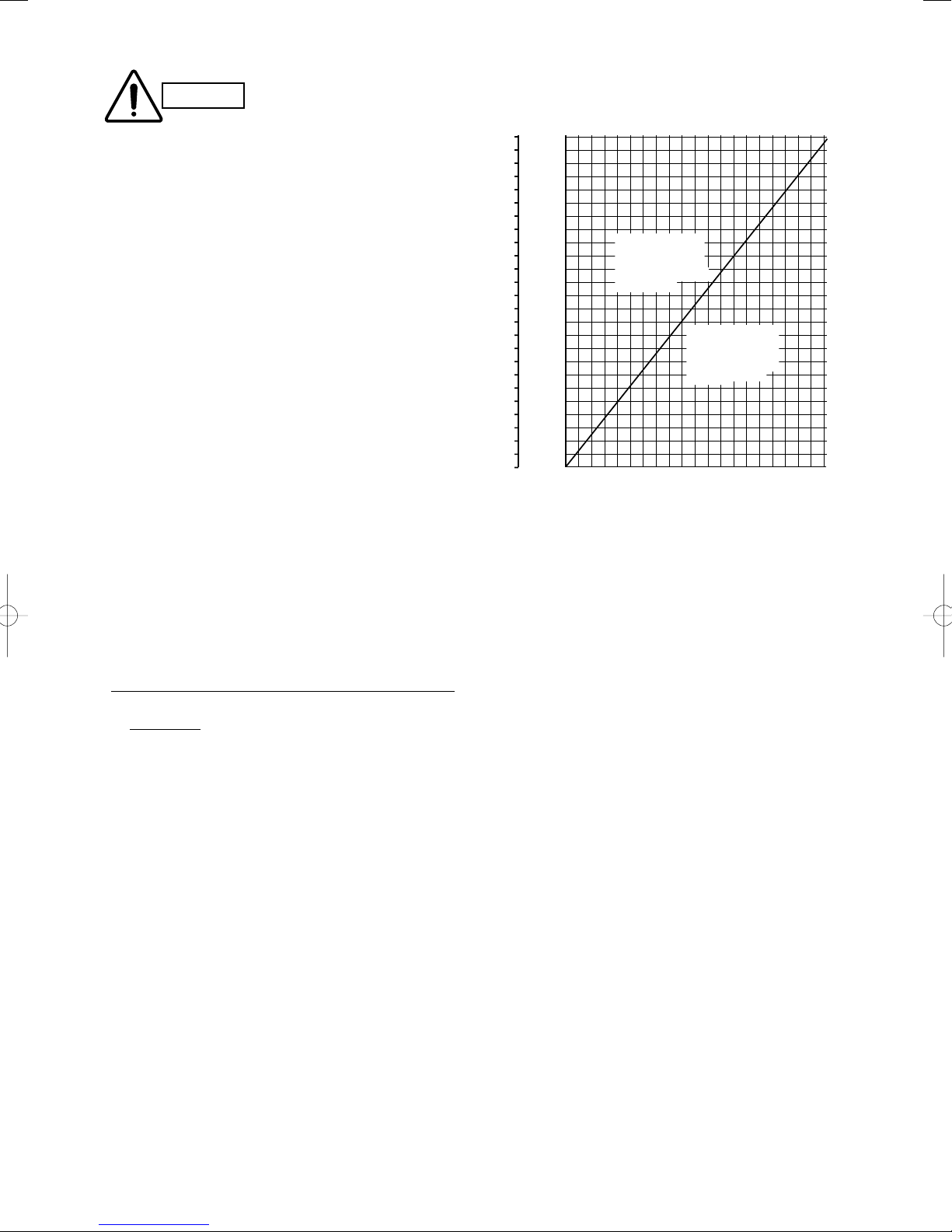
CAUTION
Be sure to check the limit density for the room in which the indoor unit is installed.
Checking of limit density
Density limit is determined on the basis of the size of a room
using an indoor unit of minimum capacity.
For instance, when an indoor unit is used in a room (floor area
2
15m
× ceiling height 2.7m = room volume 40.5m3), the graph
at right shows that the maximum overall refrigerant charge
amount of limit density (0.3kg/m
3
) that is not required to install a
ventilation fan should be calculated as follows.
Due to the room volume,
Maximum overall refrigerant charge amount
= (room volume) × (limit density)
3
= 40.5 (m
) × 0.3 (kg/m3)
= 12.15 kg
Overall refrigerant charge amount for this system is 72.137(kg).
The formula for the minimum room volume should be
determined as follows.
Required minimum room volume
= (overall refrigerant charge amount) ÷ (limit density)
= 72.137 (kg) ÷ 0.3 (kg/m
3
= 240.5 (m
)
3
)
Required minimum floor area
= (minimum room volume) ÷ (ceiling height)
= 240.5 (m
= 89.1 (m
3
) ÷ 2.7 (m)
2
)
3
2
m
m
337.5
125
324.0
120
310.5
115
297.0
110
283.5
105
100
270.0
95
256.0
90
243.0
85
229.5
80
216.0
75
202.5
70
189.0
65
175.5
60
162.0
55
148.5
50
135.0
Min. indoor volume
45
Min. indoor floor area
121.5
(when the ceiling is 2.7 m high)
40
108.0
35
94.5
30
81.0
25
67.5
20
54.0
40.5
15
10
27.0
5
13.5
0
0.0
Range below the
density limit of
0.3 kg/m³
(Countermeasures
not needed)
Range above the
density limit of 0.3
kg/m³
(Countermeasures
needed)
20100 3040 6070809010050
Total amount of refrigerant
kg
Therefore an opening for ventilation is required.
< Formula for computation >
Overall refrigerant charge amount for the air conditioner: kg
(Minimum room volume for indoor unit: m3)
72.137 (kg)
=
40.5 (m³)
= 1.78 (kg/m3) > 0.3 (kg/m³)
Accordingly, it is necessary to install a ventilation fan for this
room.
17
2. SELECTING THE INSTALLATION SITE
2-1. Outdoor Unit
AVOID:
● heat sources, exhaust fans, etc.
● damp, humid or uneven locations
● indoors (no-ventilation location)
DO:
● choose a place as cool as possible.
● choose a place that is well ventilated.
● allow enough room around the unit for air intake/
exhaust and possible maintenance.
Exhaust fan
Hot air
Heat
source
Outdoor
unit
Fig. 2-1
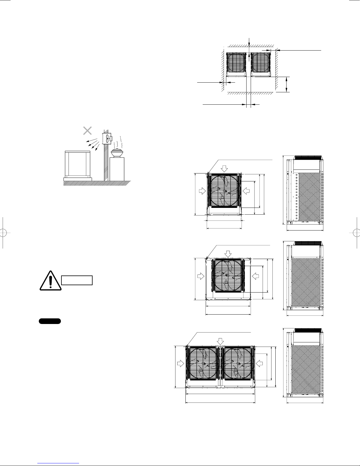
Installation Space
Install the outdoor unit where there is enough space for
ventilation. Otherwise the unit may not operate properly. Fig.
2-2 shows the minimum space requirement around the outdoor
units when 3 sides are open and only 1 side is shuttered, with
open space above the unit. The mounting base should be
concrete or a similar material that allows for adequate drainage.
Make provisions for anchor bolts, platform height, and other
site-specifi c installation requirements.
● Leave space open above the
CAUTION
NOTE
● Do not do any wiring or tubing within 30 cm of the front
panel, because this space is needed as a servicing space for
the compressor.
● Ensure a base height of 100 mm or more to ensure that
drainage water does not accumulate and freeze around the
bottom of the unit.
● If installing a drain pan, install the drain pan prior to
installing the outdoor unit.
* Make sure there is at least 150 mm between the outdoor
unit and the ground.
Also, the direction of the tubing and electrical wiring should
be from the front of the outdoor unit.
unit.
● Construct louvers or other
openings in the wall, if
necessary, to ensure adequate
ventilation.
(when 3 sides are open and only 1 side is shuttered)
Example of installation of 2 units
* More than 300 mm
** More than 50 mm
** More than
50 mm
*** More than 60 mm
*
Make a walk-in space behind the unit to erase maintenance and servicing.
** When setting the anchor bolt to position “B” or “C” (See Fig. 2-3), make
the space between the unit and the wall more than 250 mm for installation
operation.
*** When setting the anchor bolt to position “B” or “C” (See Fig. 2-3), make
the space between the outdoor units more than 180 mm for installation
operation.
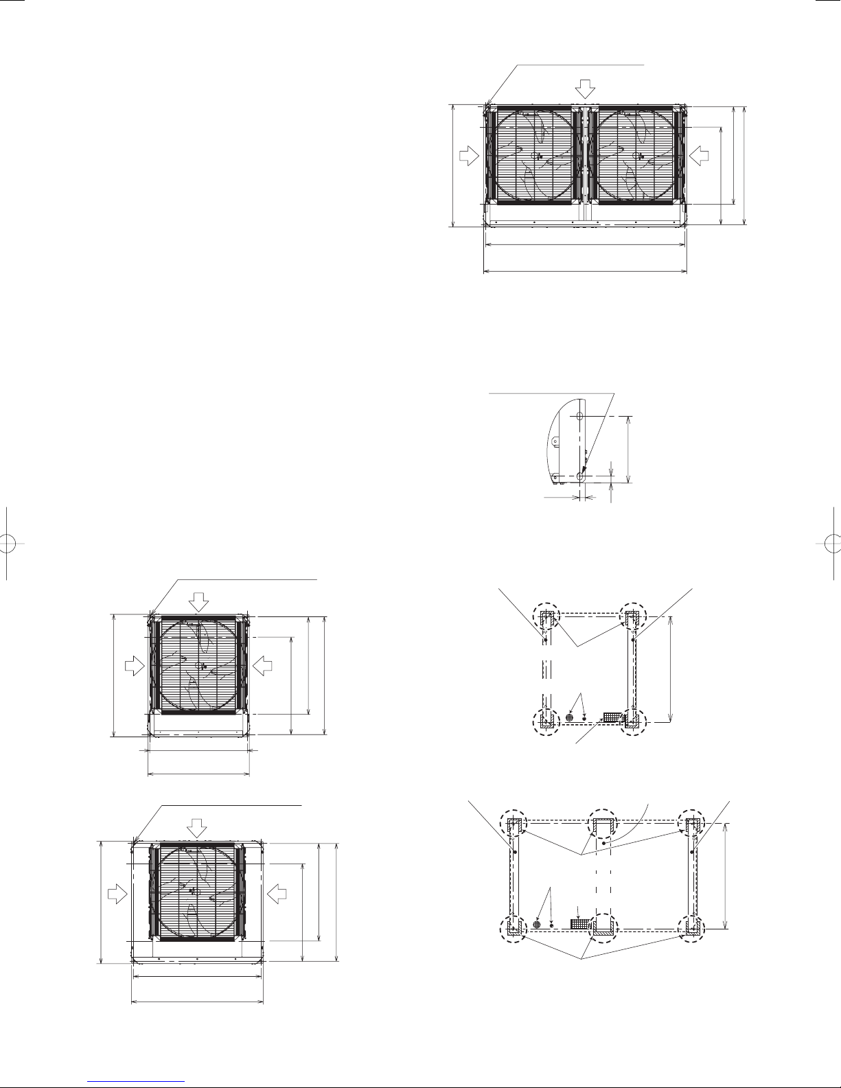
Top view
Air
intake
930
Top view
Air
intake
930
Installation anchor hole
(8 – 15 × 21 elongated holes)
740
(Installation hole pitch)
770
Installation anchor hole
(8 – 15 × 21 elongated holes)
970
(Installation hole pitch)
1000
Air intake
Air intake
Fig. 2-2
Air
intake
C
Air
intake
Side view
B
A
Side view
C
B
A
More than
500 mm
Unit: mm
1758
930
1758
930
Top view Side view
Installation anchor hole
(8 – 15 × 21 elongated holes)
Air intake
Air
intake
930
1510
(Installation hole pitch)
1540
According to the installation site, you may choose the setting position in the
*
depth direction of the anchor bolt from “A”, “B” or “C”.
A : 894 (Installation hole pitch) * For removing tube forward
B : 730 (Installation hole pitch) * For removing the tube downward
C : 730 (Installation hole pitch)
Fig. 2-3
Air
intake
B
1758
A
C
930
18
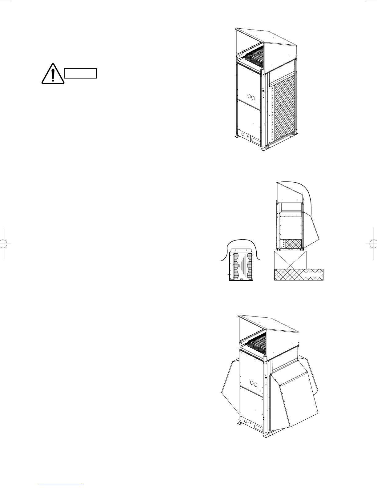
2-2. Shield for Horizontal Exhaust Discharge
It is necessary to install an air-discharge chamber (fi eld supply)
to direct exhaust from the fan horizontally if it is diffi cult to
provide a minimum space of 2 m between the air-discharge
outlet and a nearby obstacle. (Fig. 2-4)
In regions with heavy snowfall,
CAUTION
the outdoor unit should be
provided with a solid, raised
platform and snow-proof vents.
(Fig. 2-5)
2-3. Installing the Outdoor Unit in Heavy Snow Areas
In locations where wind-blown snow can be a problem, snowproof vents should be fi tted to the unit and direct exposure to
the wind should be avoided as much as possible. (Fig. 2-6) The
following problems may occur if proper countermeasures are
not taken:
● The fan in the outdoor unit may stop running, causing the
unit to be damaged.
● There may be no air flow.
● The tubing may freeze and burst.
● The condenser pressure may drop because of strong wind,
and the indoor unit may freeze.
2-4. Precautions When Installing in Heavy Snow
Areas
a) The platform should be higher than the maximum snow
depth. (Fig. 2-5)
b) The 2 anchoring feet of the outdoor unit should be used for
the platform, and the platform should be installed beneath
the air-intake side of the outdoor unit.
c) The platform foundation must be solid and the unit must be
secured with anchor bolts.
d) When installing on a roof subject to strong wind,
countermeasures must be taken to prevent the unit from
being overturned.
Fig. 2-4
DO
AVOID
2-5. Dimensions of Wind Ducting
Reference diagram for air-discharge chamber
(field supply)
For further details, refer to “SUPPLEMENT”.
2-6. Dimensions of Snow Ducting
Reference diagram for snow-proof vents
(field supply)
For further details, refer to “SUPPLEMENT”.
Without snow-proof vents
(Without platform)
Fig. 2-5
Fig. 2-6
Fallen snow
With snow-proof vents
(High platform)
19
3. HOW TO INSTALL THE OUTDOOR UNIT
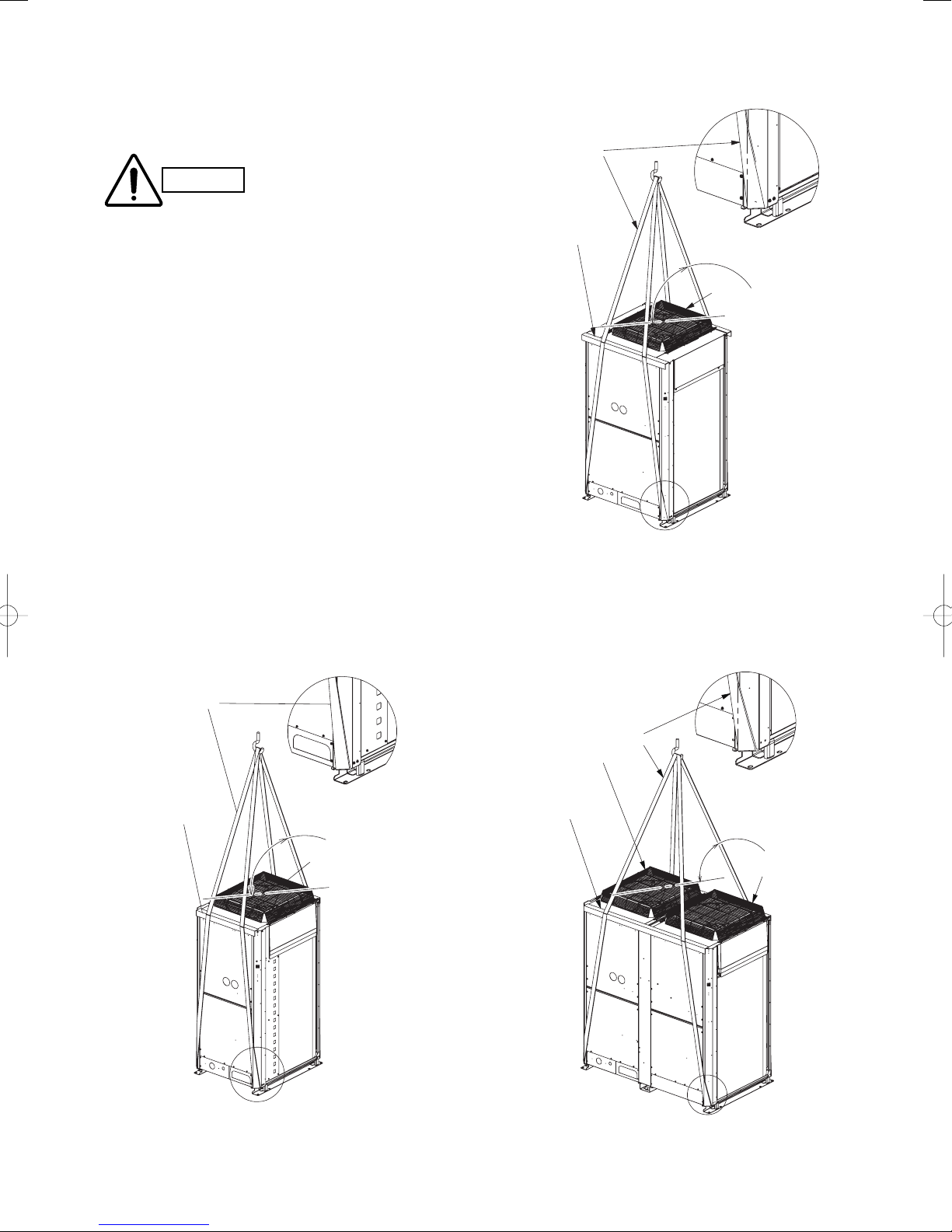
3-1.Transporting
When transporting the unit, have it delivered as close to the
installation site as possible without unpacking.
Use a hook for suspending the unit. (Fig. 3-1)
CAUTION
Model : 14 hp, 16 hp
Rope
Detailed drawing B
Detailed drawing B
● When hoisting the outdoor unit, pass ropes through the left
and right holes of the bottom plate as shown in the Figs.
3-1-1 to 3-1-3. The angle between the rope and top panel
must be 70°or more so that the rope does not come into
contact with the fan guard. Use two lengths of rope 7.5
meters long or longer.
● Hang the rope at an oblique angle of the four corners of the
bottom plate. If it is hung at other areas, the rope becomes
loose and the outdoor unit will be damaged or you may be
injured.
● Use protective panels or padding at all locations where the
rope contacts the outer casing or other parts to prevent
scratching. In particular, use protective material (such as
cloth or cardboard) to prevent the edges of the top panel
from being scratched.
Model : 8 hp, 10 hp, 12 hp
Detailed drawing A
Protective
cardboard
or cloth
Model : 18 hp, 20 hp
70° or more
Fan guard
B
Fig. 3-1-2
Detailed drawing C
Rope
Protective
Protective
cardboard
cardboard
or cloth
or cloth
A
Fig. 3-1-1
70° or more
Fan guard
20
Fan guard
Protective
cardboard
or cloth
Rope
Fig. 3-1-3
70° or more
Fan guard
Fan guard
C
3-2. Installing the Outdoor Unit
(1) Use four (4) anchor bolts (M12 or similar) to securely anchor
the unit. Regarding the positioning anchor bolts of the
depth direction, select one of three types according to the
installation site. (See Fig. 3-2 A, B, C.)
Normally, select the position “A”. When removing the
connection tube in a downward direction, select the position
“B”.
(2) When only using a single outdoor unit, see the Figure 3-2.
In case of the combination with different units, refer to
“SUPPLEMENT”.
* When positioning the anchor bolt at “B” or “C”, make a
sufficient space bewteen the units or from the wall for
installation.
(Make a space between the units wider than 180mm and
left and right space wider than 250mm from the wall.)
(3) The vibration insulator or the like should be kept secure to
satisfy the width and depth of 100mm for the plate legs.
(See the dimensions marked by the asterisk at Fig. 3-4d 3-4g.) Use a washer from the upper direction larger than
the hole size for fixing the installation. The models 18 hp
and 20 hp have four (4) anchor volts respectively as same
as others. Two models, however, additionally need the
vibration insulator under the plate leg at the central location
for the installation site. Screw or wire the vibration insulator
at the center of the unit to the rack or the basement.
Be sure to use the same thickness of all vibration insulators
and make adjustment so that they will become the same
height each other. (Fig. 3-3 and Fig. 3-4)
Air
intake
930
Installation anchor hole
(8 – 15 × 21 elongated holes)
Air intake
Air
C
intake
B
Unit: mm
A
Installation anchor hole
(8 – 15 × 21 elongated holes)
Air intake
Air
intake
930
1510
(Installation hole pitch)
1540
Unit: mm
Air
intake
B
C
A
Top view
•
According to the installation site, you may choose the setting position in
the depth direction of the anchor bolt from “A”, “B” or “C”.
A :894 (Installation hole pitch) * The tubing is routed out from the front.
B :730 (Installation hole pitch) * The tubing is routed out from the bottom.
C :730 (Installation hole pitch)
Fig. 3-2c
(Detailed view of anchor hole)
8 – 15 × 21 elongated hole
15
182
18
Unit: mm
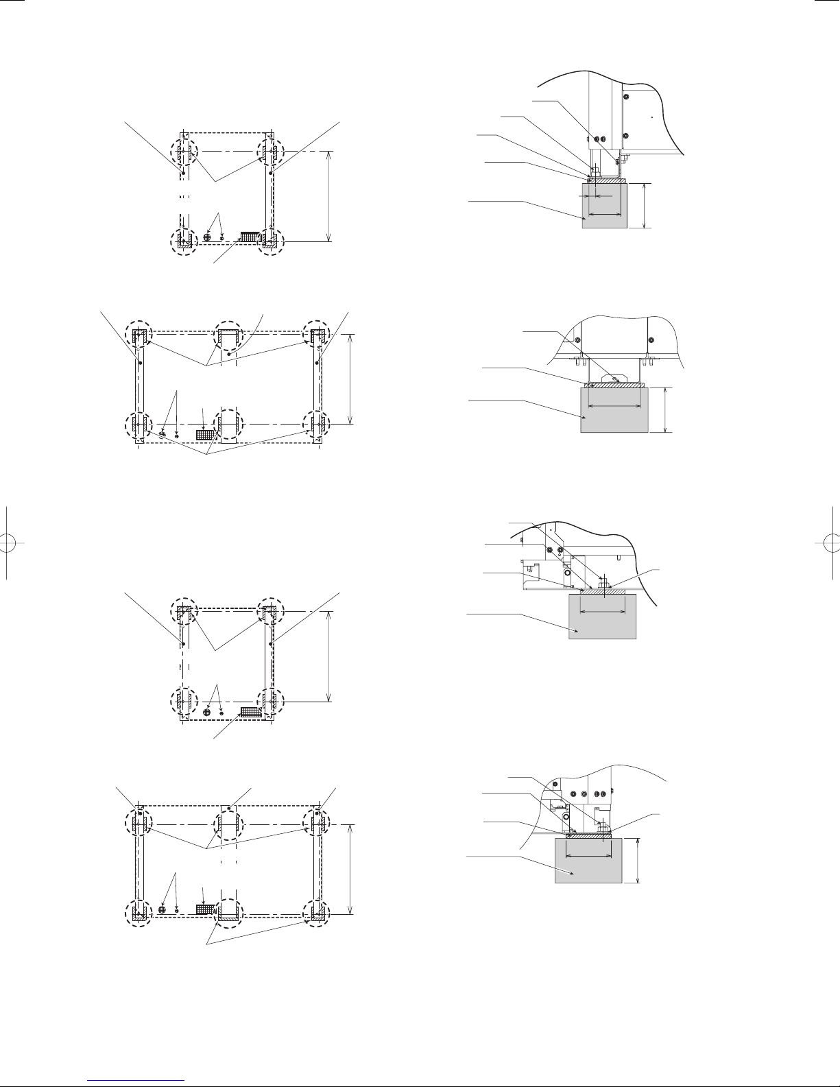
Fig. 3-3
• Below shows vibration insulator position when setting anchor
bolt at position A (Fig.3-2).
Model : 8 hp, 10 hp, 12 hp, 14 hp, 16 hp
Plate leg (left) Plate leg (right)
Unit: mm
DD
Vibration insulator
Electrical wiring port(bottom)
A : 894
740
(Installation hole pitch)
770
Top view
Installation anchor hole
(8 – 15 × 21 elongated holes)
Air intake
Air
intake
930
970
(Installation hole pitch)
1000
Air
intake
Top view
C
Unit: mm
B
A
Fig. 3-2a
Fig. 3-2b
(Installation hole pitch)
DD
Tubing port (bottom)
Model : 18 hp, 20 hp
Plate leg (left) Plate leg (right)
D
Electrical wiring port(bottom)
D
* Need the vibration insulator under the plate leg at the central
location for the installation site.
21
Plate leg (center)
F
Vibration insulator
Tubing port (bottom)
F
Vibration insulator
D
A : 894
(Installation hole pitch)
D
Fig. 3-4a
*100
100
100
*71
15
100
*116
*100
• Below shows vibration insulator position when setting anchor
bolt at position B (Fig.3-2).
Model : 0706, 0906, 1156, 1306, 1406
Model : 8 hp, 10 hp, 12 hp, 14 hp, 16 hp
Plate leg (left) Plate leg (right)
Unit: mm
EE
Vibration insulator
Electrical wiring port(bottom)
DD
Tubing port (bottom)
Model : 18 hp, 20 hp
Plate leg (left)
D
Plate leg (center)
B : 730
(Installation hole pitch)
Plate leg (right)
DF
Detailed view of “D” & “E”
Plate leg (left, right)
Anchor bolts
Washer
Vibration
insulator
Base
Detailed view of “F” & “G”
Plate leg (center)
Unit: mm
or more
Front view
Fig. 3-4d
Unit: mm
Vibration insulator
Electrical wiring port(bottom)
Tubing port (bottom)
E
Vibration insulator
* Need the vibration insulator under the plate leg at the
central location for the installation site.
• Below shows vibration insulator position when setting anchor
bolt at position C (Fig.3-2).
Model : 8 hp, 10 hp, 12 hp, 14 hp, 16 hp
Plate leg (left) Plate leg (right)
DD
Vibration insulator
Electrical wiring port(bottom)
G
E
Tubing port (bottom)
Model : 18 hp, 20 hp
Plate leg (left) Plate leg (right)
E
Electrical wiring port(bottom)
D
* Need the vibration insulator under the plate leg at the central
location for the installation site.
Plate leg (center)
G
Vibration insulator
Tubing port (bottom)
F
Vibration insulator
Vibration
insulator
B : 730
(Installation hole pitch)
E
Fig. 3-4b
Base
Detailed view of “E” & “G”
Anchor bolts**
Plate leg
(left, right or center)
Vibration
insulator
Base
Front view
Side view
or more
Unit: mm
Washer
Fig. 3-4e
**
C : 730
** Anchor bolt & washer are not reqired at the central plate leg
E
(Installation hole pitch)
(G).
Detailed view of “D” & “F ”
Anchor bolts**
Plate leg
(left, right)
Vibration
insulator
Fig. 3-4f
Unit: mm
Washer**
E
Base
C : 730
(Installation hole pitch)
D
Fig. 3-4c
Side view
** Anchor bolt & washer are not reqired at the central plate leg
(F).
22
or more
Fig. 3-4g
 Loading...