


U-72MF2U9
U-96MF2U9
U-120MF2U9
U-144MF2U9
U-72MF2U94
U-96MF2U94
Order No. SBPAC1509017CE
3WAY VRF System
U-120MF2U94
U-144MF2U94
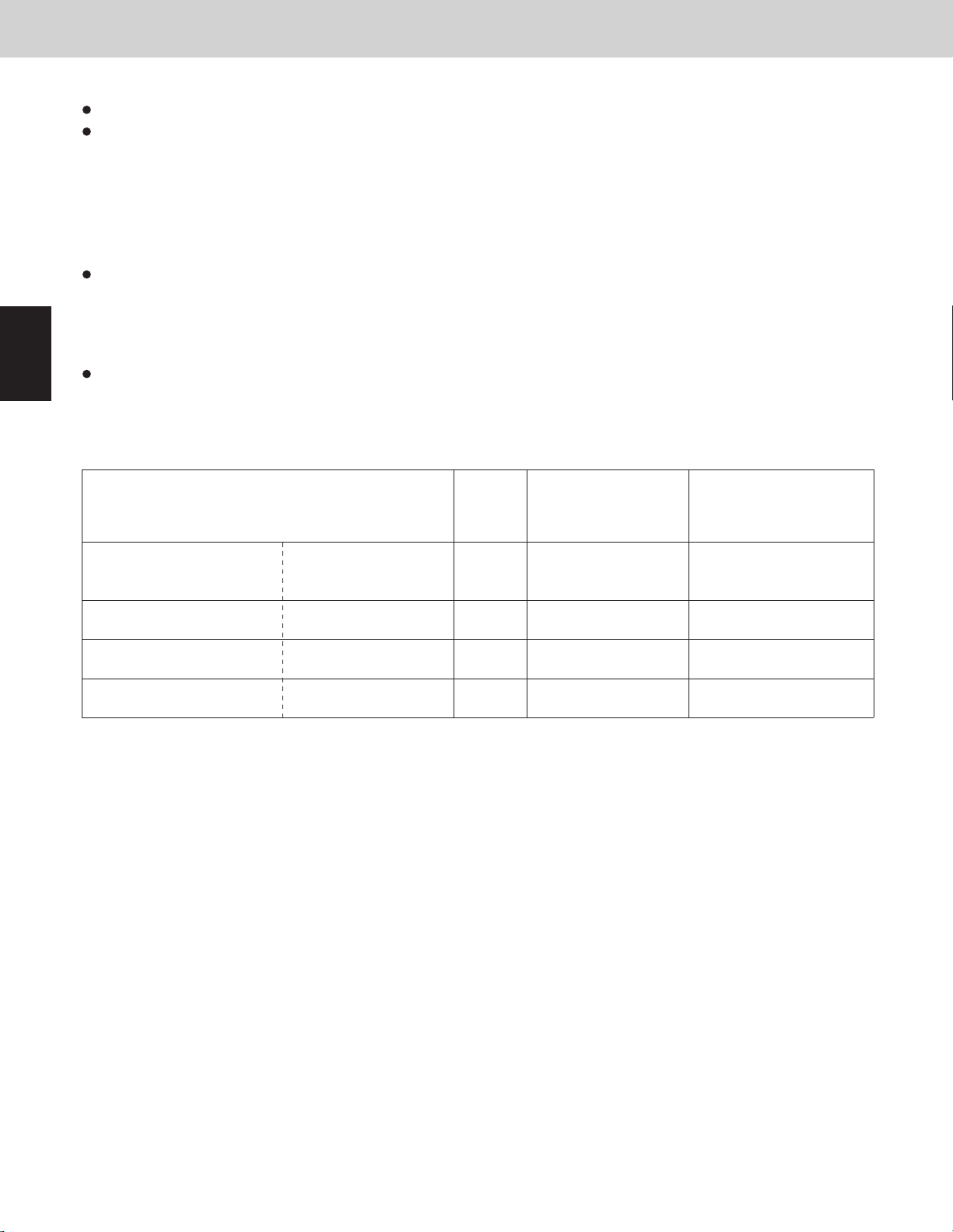
Model No.
Outdoor Unit
Outdoor Unit TypeType
MF2 3WAY VRF System
To be connecting Indoor Units
Indoor Units
Indoor Unit TypeType
U2 4-Way Cassette 36"x36"
4-Way Cassette 24"x24"
Y2
D1
1-Way Cassette
Concealed Duct
F2
-Medium Static
Concealed Duct
M2
-Low Static
Concealed Duct
E1
-High Static
T2
Ceiling
K2
Wall Mounted
P1
Floor Standing
R1
Concealed Floor Standing
S-07MD1U6
S-07MF2U6
S-07MM2U6
S-07MK2U6
S-07MP1U6
S-07MR1U6
Nominal Capacity
72 96 120 144
U-72MF2U9
U-72MF2U94
7 9 12 15 18 24 36 48 54
S-12MU2U6S-09MU2U6S-07MU2U6
S-09MY2U6S-07MY2U6
S-09MD1U6
S-09MF2U6
S-09MM2U6
S-09MK2U6
S-09MP1U6
S-09MR1U6
S-12MY2U6
S-12MD1U6
S-12MF2U6
S-12MM2U6
S-12MT2U6
S-12MK2U6
S-12MP1U6
S-12MR1U6
U-96MF2U9 U-120MF2U9 U-144MF2U9
U-96MF2U94 U-120MF2U94 U-144MF2U94
Nominal Capacity
S-15MF2U6
S-15MM2U6
S-15MP1U6
S-15MR1U6
S-18MY2U6
S-18MF2U6
S-18MM2U6
S-18MT2U6
S-18MK2U6
S-18MP1U6
S-18MR1U6
S-24MU2U6
S-24MF2U6
S-24MT2U6
S-24MK2U6
S-24MP1U6
S-24MR1U6
S-36MU2U6
S-36MF2U6
S-36ME1U6
S-48MF2U6 S-54MF2U6
S-48ME1U6
85464849346003
This air conditioner uses the refrigerant R410A.
REFERENCE NO.
SM830246-03
•Donotleakrefrigerantwhilepipingworkforan
installationorre-installation,andwhilerepairing
refrigerationparts.
Handleliquidrefrigerantcarefullyasitmaycause
frostbite.
When Servicing
•TurnthepowerOFFatthemainpowerbox(mains)
beforeopeningtheunittocheckorrepairelectrical
partsandwiring.
•Keepyourfingersandclothingawayfromanymoving
parts.
•Cleanupthesiteafteryounish,rememberingto
checkthatnometalscrapsorbitsofwiringhavebeen
leftinsidetheunit.
WARNING
•Thisproductmustnotbemodiedor
disassembledunderanycircumstances.
Modiedordisassembledunitmaycausere,
electricshockorinjury.
•Donotcleaninsidetheindoorandoutdoor
unitsbyusers.Engageauthorizeddealeror
specialistforcleaning.
•Incaseofmalfunctionofthisappliance,do
notrepairbyyourself.Contacttothesales
dealerorservicedealerforarepair.
CAUTION
•Donottouchtheairinletorthesharp
aluminumfinsoftheoutdoorunit.Yo u
maygetinjured.
• Ventilateanyenclosedareaswheninstallingor
testingtherefrigerationsystem.Leaked
refrigerantgas,oncontactwithfireorheat,can
producedangerouslytoxicgas.
• Conrmafterinstallationthatnorefrigerantgas
isleaking.Ifthegascomesincontactwitha
burningstove,gaswaterheater,electricroom
heaterorotherheatsource,itcancausethe
generationoftoxicgas.
Others
CAUTION
•Donotsitorstepontheunit,youmay
falldownaccidentally.
•Donottouchtheairinletorthesharp
aluminumfinsoftheoutdoorunit.
Yo u maygetinjured.
•DonotstickanyobjectintotheFA N
CASE.
Yo u maybeinjuredandtheunitmay
bedamaged.
Check of Density Limit
The room in which the air conditioner is to be
installed requires a design that in the event of
refrigerant gas leaking out, its density will not exceed
a set limit.
Therefrigerant(R410A),whichisusedintheair
conditioner,issafe,withoutthetoxicityorcombustibilityof
ammonia,andisnotrestrictedbylawsimposedtoprotect
theozonelayer.However,sinceitcontainsmorethanair,
itposestheriskofsuffocationifitsdensityshouldrise
excessively.Suffocationfromleakageofrefrigerantis
almostnon-existent.Withtherecentincreaseinthe
numberofhighdensitybuildings,however,theinstallation
ofmultiairconditionersystemsisontheincrease
becauseoftheneedforeffectiveuseofoorspace,
individualcontrol,energyconservationbycurtailingheat
andcarryingpower,etc.
Mostimportantly,themultiairconditionersystemisable
toreplenishalargeamountofrefrigerantcomparedto
conventionalindividualairconditioners.
Ifasingleunitofthemultiairconditionersystemistobe
installedinasmallroom,selectasuitablemodeland
installationproceduresothatiftherefrigerant
accidentallyleaksout,itsdensitydoesnotreachthelimit
(andintheeventofanemergency,measurescanbe
madebeforeinjurycanoccur).
ASHRAEandtheInternationalMechanicalCodeofthe
ICCaswellasCSAprovideguidanceanddefine
safeguardsrelatedtotheuseofrefrigerants,allofwhich
defineaRefrigerantConcentrationLevel(RCL)of 400 oz
(11.3kg)per1,000ft3(28.3m
3
)for
R410Arefrigerant.
Foradditionalguidanceandprecautionsrelatedto
refrigerantsafety,pleaserefertothefollowingdocuments:
InternationalMechanicalCode2012(IMC-2012)
(ormorerecentlyrevised)
ASHRAE15
ASHRAE34
IMPORTANT!
Please Read Before Starting
This air conditioning system meets strict safety and
operating standards. As the installer or service person, it is
an important part of your job to install or service the
system so it operates safely and efficiently.
For safe installation and trouble-free operation, you
must:
Carefully read this instruction booklet before beginning.
Follow each installation or repair step exactly as shown.
This air conditioner shall be installed in accordance with
National Wiring Regulations.
Pay close attention to all warning and caution notices
given in this manual.
WARNING
CAUTION
If Necessary, Get Help
These instructions are all you need for most installation
sites and maintenance conditions. If you require help for a
special problem, contact our sales/service outlet or your
certified dealer for additional instructions.
In Case of Improper Installation
The manufacturer shall in no way be responsible for
improper installation or maintenance service, including
failure to follow the instructions in this document.
SPECIAL PRECAUTIONS
• Do not supply power to the unit until all wiring and tubing
are completed or reconnected and checked.
• Highly dangerous electrical voltages are used in this system.
Carefully refer to the wiring diagram and these instructions
when wiring. Improper connections and inadequate
grounding can cause accidental injury or death.
• Ground the unit following local electrical codes.
• Connect all wiring tightly. Loose wiring may cause over-
heating at connection points and a possible fire hazard.
• To prevent possible hazards from insulation failure,
the unit must be grounded.
• This equipment is strongly recommended to be installed
with Earth Leakage Circuit Breaker (ELCB) or Residual
Current Device (RCD). Otherwise, it may cause electrical
shock and fire in case of equipment breakdown or
insulation breakdown.
WARNING
ELECTRICAL SHOCK CAN CAUSE
SEVERE PERSONAL INJURY OR DEATH.
ONLY A QUALIFIED, EXPERIENCED
ELECTRICIAN SHOULD ATTEMPT TO
WIRE THIS SYSTEM.
This symbol refers to a hazard or
unsafe practice which can result
in severe personal injury or death.
This symbol refers to a hazard or
unsafe practice which can result
in personal injury or product or
property damage.
When Wiring
When Transporting
Be careful when picking up and moving the indoor and
outdoor units. Get a partner to help, and bend your knees
when lifting to reduce strain on your back. Sharp edges or
thin aluminum fins on the air conditioner can cut your
fingers.
When Installing…
Select an installation location which is rigid and strong
enough to support or hold the unit, and select a location for
easy maintenance.
…In a Room
Properly insulate any tubing run inside a room to prevent
“sweating” that can cause dripping and water damage to
walls and floors.
…In Moist or Uneven Locations
Use a raised concrete pad or concrete blocks to provide a
solid, level foundation for the outdoor unit. This prevents
water damage and abnormal vibration.
…In an Area with High Winds
Securely anchor the outdoor unit down with bolts and a
metal frame. Provide a suitable air baffle.
…In a Snowy Area (for Heat Pump-type Systems)
Install the outdoor unit on a raised platform that is higher
than drifting snow. Provide snow vents.
When Connecting Refrigerant Tubing
• Pay particular attention to refrigerant leakages.
• Ventilate the room immediately, in the event that is
refrigerant gas leaks during the installation. Be careful not
to allow contact of the refrigerant gas with a flame as this
will cause the generation of toxic gas.
• Keep all tubing runs as short as possible.
• Apply refrigerant lubricant to the matching surfaces of the
flare and union tubes before connecting them, then tighten
the nut with a torque wrench for a leak-free connection.
• Check carefully for leaks before starting the test run.
i
CAUTION
Keep the fire alarm and the air
outlet at least 5 ft. (1.5 m) away
from the unit.
WARNING
• When performing piping work, do not mix air
except for specified refrigerant (R410A) in
refrigeration cycle. It causes capacity down, and
risk of explosion and injury due to high tension
inside the refrigerant cycle.
• If the refrigerant comes in contact with a flame,
it produces a toxic gas.
• Do not add or replace refrigerant other than
specified type. It may cause product damage,
burst and injury, etc.
•Donotleakrefrigerantwhilepipingworkforan
installationorre-installation,andwhilerepairing
refrigerationparts.
Handleliquidrefrigerantcarefullyasitmaycause
frostbite.
When Servicing
•TurnthepowerOFFatthemainpowerbox(mains)
beforeopeningtheunittocheckorrepairelectrical
partsandwiring.
•Keepyourfingersandclothingawayfromanymoving
parts.
•Cleanupthesiteafteryounish,rememberingto
checkthatnometalscrapsorbitsofwiringhavebeen
leftinsidetheunit.
CAUTION
•Donottouchtheairinletorthesharp
aluminumfinsoftheoutdoorunit.Yo u
maygetinjured.
• Ventilateanyenclosedareaswheninstallingor
testingtherefrigerationsystem.Leaked
refrigerantgas,oncontactwithfireorheat,can
producedangerouslytoxicgas.
• Conrmafterinstallationthatnorefrigerantgas
isleaking.Ifthegascomesincontactwitha
burningstove,gaswaterheater,electricroom
heaterorotherheatsource,itcancausethe
generationoftoxicgas.
WARNING
•Thisproductmustnotbemodiedor
disassembledunderanycircumstances.
Modiedordisassembledunitmaycausere,
electricshockorinjury.
•Donotcleaninsidetheindoorandoutdoor
unitsbyusers.Engageauthorizeddealeror
specialistforcleaning.
•Incaseofmalfunctionofthisappliance,do
notrepairbyyourself.Contacttothesales
dealerorservicedealerforarepair.
Check of Density Limit
The room in which the air conditioner is to be
installed requires a design that in the event of
refrigerant gas leaking out, its density will not exceed
a set limit.
Therefrigerant(R410A),whichisusedintheair
conditioner,issafe,withoutthetoxicityorcombustibilityof
ammonia,andisnotrestrictedbylawsimposedtoprotect
theozonelayer.However,sinceitcontainsmorethanair,
itposestheriskofsuffocationifitsdensityshouldrise
excessively.Suffocationfromleakageofrefrigerantis
almostnon-existent.Withtherecentincreaseinthe
numberofhighdensitybuildings,however,theinstallation
ofmultiairconditionersystemsisontheincrease
becauseoftheneedforeffectiveuseofoorspace,
individualcontrol,energyconservationbycurtailingheat
andcarryingpower,etc.
Mostimportantly,themultiairconditionersystemisable
toreplenishalargeamountofrefrigerantcomparedto
conventionalindividualairconditioners.
Others
CAUTION
•Donotsitorstepontheunit,youmay
falldownaccidentally.
•Donottouchtheairinletorthesharp
aluminumfinsoftheoutdoorunit.
Yo u maygetinjured.
•DonotstickanyobjectintotheFA N
CASE.
Yo u maybeinjuredandtheunitmay
bedamaged.
Ifasingleunitofthemultiairconditionersystemistobe
installedinasmallroom,selectasuitablemodeland
installationproceduresothatiftherefrigerant
accidentallyleaksout,itsdensitydoesnotreachthelimit
(andintheeventofanemergency,measurescanbe
madebeforeinjurycanoccur).
ASHRAEandtheInternationalMechanicalCodeofthe
ICCaswellasCSAprovideguidanceanddefine
safeguardsrelatedtotheuseofrefrigerants,allofwhich
defineaRefrigerantConcentrationLevel(RCL)of 400 oz
(11.3kg)per1,000ft3(28.3m
Foradditionalguidanceandprecautionsrelatedto
refrigerantsafety,pleaserefertothefollowingdocuments:
InternationalMechanicalCode2012(IMC-2012)
(ormorerecentlyrevised)
ASHRAE15
ASHRAE34
3
)for
R410Arefrigerant.
ii
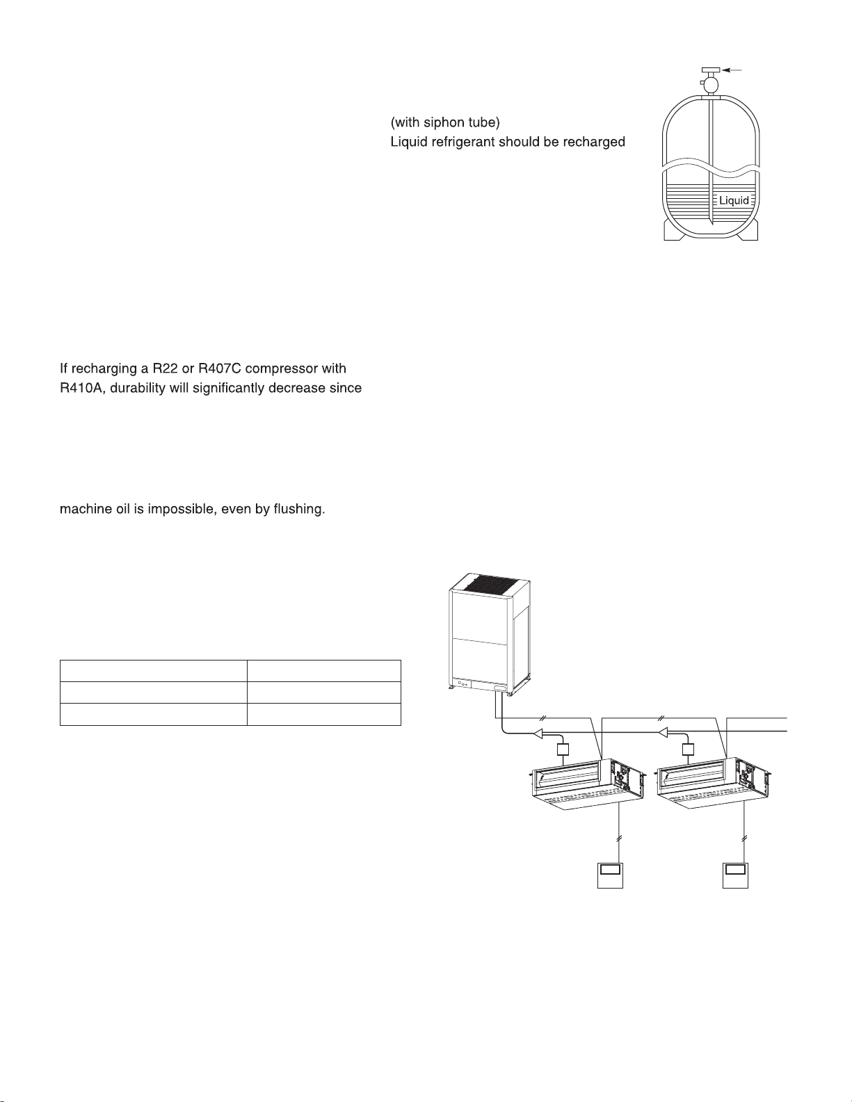
3-2. Use R410A exclusive cylinder only.
Single-outlet valve
with the cylinder standing on end as
shown.
New refrigerant R410A cannot be used for
earlier models
1. Compressor specifications are different.
some of the materials used for compressor parts are
different.
2. Existing tubing cannot be used (especially R22).
Completely cleaning out residual refrigerating
3. Refrigerating machine oil differs (R22).
Since R22 refrigerating machine oil is mineral oil, it
does not dissolve in R410A. Therefore, refrigerating
machine oil discharged from the compressor can
cause compressor damage.
R22 refrigerating machine oil Mineral oil (Suniso oil)
R407C refrigerating machine oil Synthetic fluid (ether oil)
R410A refrigerating machine oil Synthetic fluid (ether oil)
Valve
Precautions for Installation Using New Refrigerant
1. Care regarding tubing
1-1. Process tubing
l
Material: Use clean, dry, free of oil, refrigeration grade, seamless, phosphorous deoxidized copper tube rated for
R410A only. Wall thickness shall comply with the applicable legislation. The minimal wall thickness must be in
accordance with the table below.
l
Tubing size: Be sure to use the sizes indicated in the table below.
l
Use a tube cutter when cutting the tubing, and be sure to remove any flash. This also applies to distribution joints
(optional).
l
When bending tubing, use a bending radius that is 4 times the outer diameter of the tubing or larger.
Use sufficient care in handling the tubing. Seal the tubing ends with caps or tape to
CAUTION
prevent dirt, moisture, or other foreign substances from entering.
These substances can result in system malfunction.
Outer diameter Wall thickness Outer diameter Wall thickness
5/8" (15.88) 0.040 (1.016) 1-5/8" (41.28) 0.060 (1.524)
3/4" (19.05) 0.042 (1.0668) Unit: in. (mm)
Material: O Material: O
1/4" (6.35) 0.025 (0.635) 7/8" (22.22) 0.045 (1.143)
3/8" (9.52) 0.030 (0.762) 1-1/8" (28.58) 0.050 (1.27)
1/2" (12.7) 0.035 (0.889) 1-3/8" (34.92) 0.055 (1.397)
1-2. Prevent impurities including water, dust and oxide from entering the tubing. Impurities can cause R410A
refrigerant deterioration and compressor defects. Due to the features of the refrigerant and refrigerating machine
oil, the prevention of water and other impurities becomes more important than ever.
2. Be sure to recharge the refrigerant only in liquid form.
2-1. Since R410A is a non-azeotrope, recharging the refrigerant in gas form can lower performance and cause defects
in the unit.
2-2. Since refrigerant composition changes and performance decreases when gas leaks, collect the remaining
refrigerant and recharge the required total amount of new refrigerant after fixing the leak.
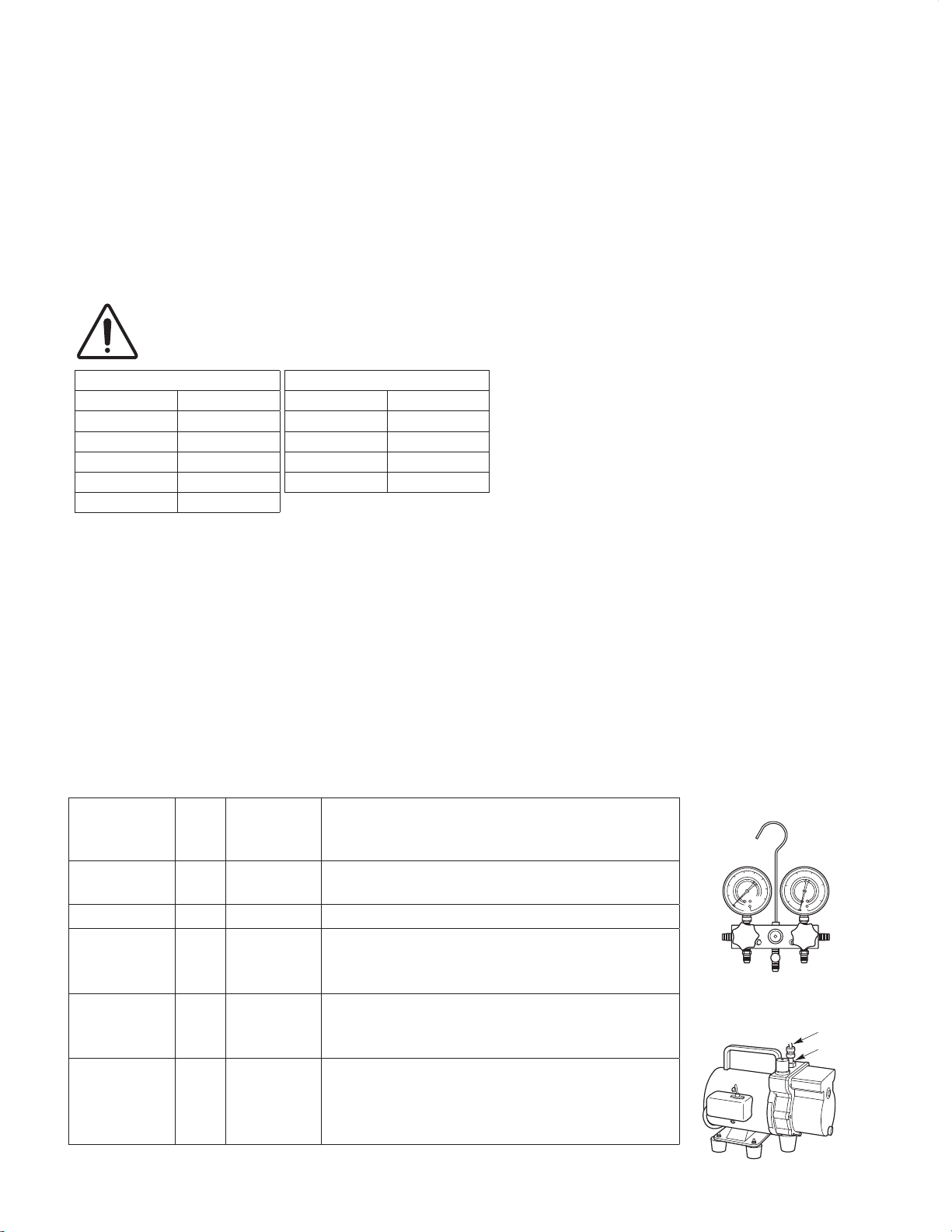
3. Different tools required
3-1. Tool specifications have been changed due to the characteristics of R410A.
Some tools for R22- and R407C-type refrigerant systems cannot be used.
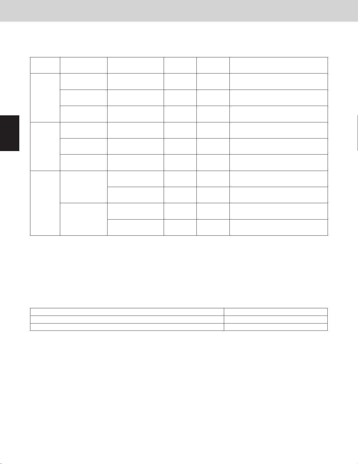
Item
Manifold gauge Yes No
Charge hose Yes No To resist higher pressure, material must be changed.
Vacuum pump Yes Yes
Leak detector Yes No
Flaring oil Yes No
* Using tools for R22 and R407C and new tools for R410A together can cause defects.
tools?
New
R407C tools
compatible
with R410A?
Remarks
Types of refrigerant, refrigerating machine oil, and
pressure gauge are different.
Use a conventional vacuum pump if it is equipped with
a check valve. If it has no check valve, purchase and
attach a vacuum pump adapter.
Leak detectors for CFC and HCFC that react to chlorine
do not function because R410A contains no chlorine.
Leak detector for HFC134a can be used for R410A.
For systems that use R22, apply mineral oil (Suniso
oil) to the flare nuts on the tubing to prevent refrigerant
leakage. For machines that use R407C or R410A, apply
synthetic oil (ether oil) to the flare nuts.
Manifold gauge
Vacuum pump
Outlet
Inlet
iii
3-2. Use R410A exclusive cylinder only.
New refrigerant R410A cannot be used for
earlier models
1. Compressor specifications are different.
some of the materials used for compressor parts are
different.
Valve
Single-outlet valve
with the cylinder standing on end as
shown.
2. Existing tubing cannot be used (especially R22).
Completely cleaning out residual refrigerating
3. Refrigerating machine oil differs (R22).
Since R22 refrigerating machine oil is mineral oil, it
does not dissolve in R410A. Therefore, refrigerating
machine oil discharged from the compressor can
cause compressor damage.
R22 refrigerating machine oil Mineral oil (Suniso oil)
R407C refrigerating machine oil Synthetic fluid (ether oil)
R410A refrigerating machine oil Synthetic fluid (ether oil)
iv

—
CONTENTS
—
Section 1: CONTROL FUNCTIONS .......................................... 1-1
1. Introduction .............................................................1-2
2. Selecting Outdoor Unit for Operation .......................................... 1-3
3. Compressor Control .......................................................1-5
4. Output of PCB ..........................................................1-14
5. Outdoor Fan Control .....................................................1-20
6. Outdoor Unit CCU (command controller unit) Control ............................1-24
7. Tube Refrigerant Recovery Control ..........................................1-28
8. Oil Control .............................................................1-30
9. Defrost Control ..........................................................1-33
10. Discharge Tube Accumulated Refrigerant Recovery Control ....................... 1-39
11. Upper Current Limitation Mode (Demand control) ............................... 1-40
12. Backup Operation ....................................................... 1-42
13. Other Functions .........................................................1-46
14. Detailed Settings in EEPROM of Outdoor Unit .................................1-48
15. Outdoor Unit Control PCB .................................................1-50
Section 2: OUTDOOR UNIT REPAIR PROCEDURES ........................... 2-1
1. Removing Panels ......................................................... 2-2
2. Discharging Compressor Oil ................................................ 2-4
3. Backup Operation ........................................................ 2-7
4. Recovering Refrigerant .................................................... 2-9
5. Checking for Leakage After Repair .......................................... 2-14
6. Evacuating System ...................................................... 2-15
7. Charging Compressor Oil ................................................. 2-16
8. Pumping Out Refrigerant from Outdoot Unit ................................... 2-22
9. Compressor ........................................................... 2-26
10. Replacing Peripheral Parts of Fusible Plug .................................... 2-36
11. High and Low Pressure Sensors ............................................ 2-37
Section 3: OUTDOOR UNIT MAINTENANCE REMOTE CONTROLLER ............. 3-1
1. Overview ...............................................................3-2
2. Functions ...............................................................3-3
3. Ordinary Display Controls and Functions ...................................... 3-4
4. Monitoring Operations .....................................................3-9
5. Outdoor Unit Alarm History Monitor .......................................... 3-11
6. Mode Settings ..........................................................3-12
Section 4: REMOTE CONTROLLER FUNCTIONS ............................. 4-1
1. Simple Settings Function ................................................... 4-2
2. Detailed Settings Function .................................................. 4-8
3. Remote Controller Servicing Functions ....................................... 4-28
v

Section 5: TROUBLE DIAGNOSIS .......................................... 5-1
1. Contents of Remote Controller Switch Alarm Display .............................5-2
2. Outdoor Unit Control Panel LED Display .......................................5-4
3. 3WAY Alarm Codes .......................................................5-5
4. Blinking Inspection Display on the Remote Controller ............................5-30
5. Inspection and Characteristics of Parts .......................................5-31
6. Test Pin ...............................................................5-35
7. Symptom: Thermostat in OFF continues or cycles OFF & ON too frequently ..........5-36
Section 6: TEST RUN .................................................... 6-1
1. Preparing for Test Run ..................................................... 6-2
2. Test Run Procedure ....................................................... 6-3
3. Main Outdoor Unit PCB Setting ..............................................6-4
4. Function Switches on P. C. Board ............................................6-7
5. Auto Address Setting ......................................................6-8
6. Setting Test Run Remote Controller. . . . . . . . . . . . . . . . . . . . . . . . . . . . . . . . . . . . . . . . . . 6-16
7. Caution for Pump Down ................................................... 6-17
8. Self-Diagnosis Function Table and Contents of Alarm Display ..................... 6-17
vi

– MEMO –
vii

3WAY VRF SYSTEM
2WAY VRF SYSTEM
Control Functions
Contents
Contents
Introduction .....................................................................................................................
1. 1-2
Selecting Outdoor Unit for Operation ...........................................................................
2.
Compressor Control .......................................................................................................
3.
Output of PCB ...............................................................................................................
4.
Outdoor Fan Control .....................................................................................................
5.
Outdoor Unit CCU (command controller unit) Control ..............................................
6.
1. CONTROL FUNCTIONS
Control Functions
1-3
1-5
1-14
1-20
1-24
7. Tube Refrigerant Recovery Control .............................................................................
Oil Control ......................................................................................................................
8.
Defrost Control ..............................................................................................................
9.
Discharge Tube Accumulated Refrigerant Recovery Control ...................................
10.
Upper Current Limitation Mode (Demand control) .....................................................
11.
Backup Operation .........................................................................................................
12.
Other Functions ............................................................................................................
13.
Detailed Settings in EEPROM of Outdoor Unit ...........................................................
14.
Outdoor Unit Control PCB ............................................................................................
15.
1-28
1-30
1-33
1-39
1-40
1-42
1-46
1-48
1-50
1
2
3
4
5
1 - 1
6
7
8
9
1
2WAY VRF SYSTEM
Control Functions
1. Introduction
2. Selecting Outdoor Unit for Operation
2-1. Outdoor Unit Operating Rules
As a result of setting the main outdoor and sub outdoor units due to the O/U.ADD setting, the order of priority for
the outdoor units is determined in small values of O/U.ADD sequence. Because in this system all outdoor units
contain an inverter compressor, ordinarily there is no absolute order of priority for compressor operation.
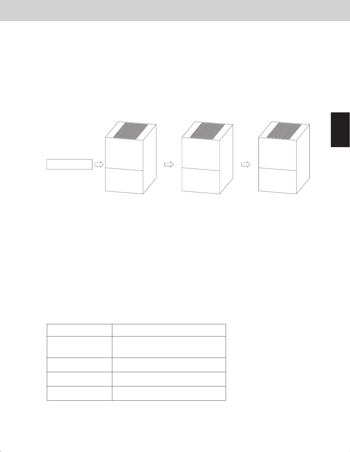
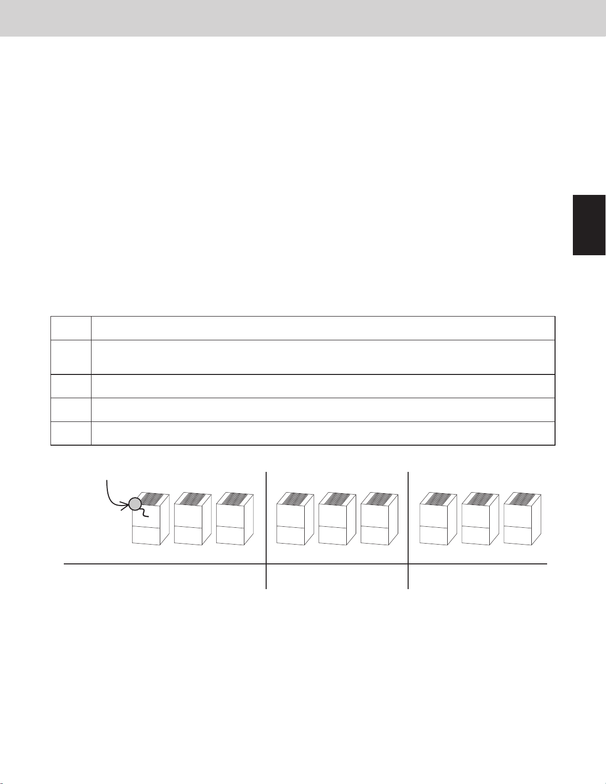
2-2. Delayed Start of Outdoor Units
2-2-1. Delayed start of outdoor unit in the same system
If it is necessary to operate the compressors simultaneously at multiple outdoor units, each outdoor unit will
start in order of unit No. every one second, beginning with unit No. 1.
*
Operation starts
Main outdoor unit Sub outdoor unit Sub outdoor unit
O/U.ADD = 1 O/U.ADD = 2 O/U.ADD = 3
Starts after 1 second Starts after 2 seconds Starts after 3 seconds
This is in order to reduce the load on the power supply equipment.
2-2-2. Delayed start for each system
When systems are linked with one communication cable and multiple systems are required to operate
simultaneously by the central control device, all main outdoor units will begin operating simultaneously.
In this situation, the load of the power supply equipment increases temporarily.
To prevent the overload, the start timing of each system can be delayed.
In order to enable this delay time, it must be set in the EEPROM for each system (Main outdoor unit).
Those systems (Main outdoor units) where this setting has been made will start after a delay according to
their system addresses.
To activate this delay start function, it is necessary to set it to EEPROM on main outdoor PCB.
EEPROM setting in main outdoor unit
CODE: 3E
2WAY VRF SYSTEM
Control Functions
Delay timeSetting No.
0
(factory preset mode)
No delay start for each system
1 (System address × 1 × 8) seconds delay
2 (System address × 2 × 8) seconds delay
3 (System address × 3 × 8) seconds delay
3WAY VRF SYSTEM
1. Introduction
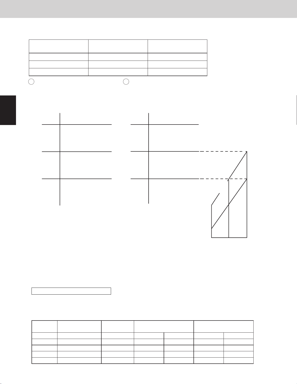
The MF2U series outdoor units for USA is a system that allows multiple outdoor units to be connected.
All the outdoor units do not utilize the sub units that were used in earlier systems.
The O/U.ADD of outdoor unit PCB where the unit is set to “1” becomes the main unit and activates
as the CCU (command controller unit) functions that controls the entire system.
PCB Setting of Outdoor Unit
In order to determine the outdoor unit to be the main or sub unit, it is necessary to make settings at each PCB.
Main outdoor unit
The outdoor unit where the O/U.ADD is set to “1” activates the CCU (command controller unit) functions that
controls the entire system. This outdoor unit is the main outdoor unit.
* For the main outdoor unit, perform all the settings in the table (PCB setting of outdoor unit) below.
Sub outdoor unit
The outdoor unit where the unit No. is set to other than “1” is a sub outdoor unit.
* The system will not operate if outdoor units have been set other than unit No. “1”.
Control Functions
2
3
4
5
6
PCB Setting of Outdoor Unit
Factory
O/U.ADD [SW5] 11Outdoor units address
R.C.ADD [SW1, SW2] 1 Not necessarySystem 1 ~ 30System address
NO.OF I/U [SW3, SW4] 1 Not necessarySystem 1 ~ 52 unitsNo. of indoor units
NO.OF O/U 1 Not necessarySystem 1 ~ 3 unitsNo. of outdoor units[SW6]
* This system can be exteded to connect a maximum of 3 outdoor units.
preset
mode
Main outdoor unit
On-site setting
Sub outdoor unit
On-site setting
Setting other than 1
(Duplication prohibited)
7
8
9
1 - 2
3WAY VRF SYSTEM
2. Selecting Outdoor Unit for Operation
2WAY VRF SYSTEM
Control Functions
2. Selecting Outdoor Unit for Operation
2-1. Outdoor Unit Operating Rules
As a result of setting the main outdoor and sub outdoor units due to the O/U.ADD setting, the order of priority for
the outdoor units is determined in small values of O/U.ADD sequence. Because in this system all outdoor units
contain an inverter compressor, ordinarily there is no absolute order of priority for compressor operation.
2-2. Delayed Start of Outdoor Units
2-2-1. Delayed start of outdoor unit in the same system
If it is necessary to operate the compressors simultaneously at multiple outdoor units, each outdoor unit will
start in order of unit No. every one second, beginning with unit No. 1.
*
This is in order to reduce the load on the power supply equipment.
Control Functions
1
Operation starts
Main outdoor unit Sub outdoor unit Sub outdoor unit
O/U.ADD = 1 O/U.ADD = 2 O/U.ADD = 3
Starts after 1 second Starts after 2 seconds Starts after 3 seconds
2-2-2. Delayed start for each system
When systems are linked with one communication cable and multiple systems are required to operate
simultaneously by the central control device, all main outdoor units will begin operating simultaneously.
In this situation, the load of the power supply equipment increases temporarily.
To prevent the overload, the start timing of each system can be delayed.
In order to enable this delay time, it must be set in the EEPROM for each system (Main outdoor unit).
Those systems (Main outdoor units) where this setting has been made will start after a delay according to
their system addresses.
To activate this delay start function, it is necessary to set it to EEPROM on main outdoor PCB.
EEPROM setting in main outdoor unit
CODE: 3E
2
3
4
5
6
Delay timeSetting No.
0
(factory preset mode)
1 (System address × 1 × 8) seconds delay
2 (System address × 2 × 8) seconds delay
3 (System address × 3 × 8) seconds delay
No delay start for each system
1 - 3
7
8
9

2. Selecting Outdoor Unit for Operation
3. Compressor Control
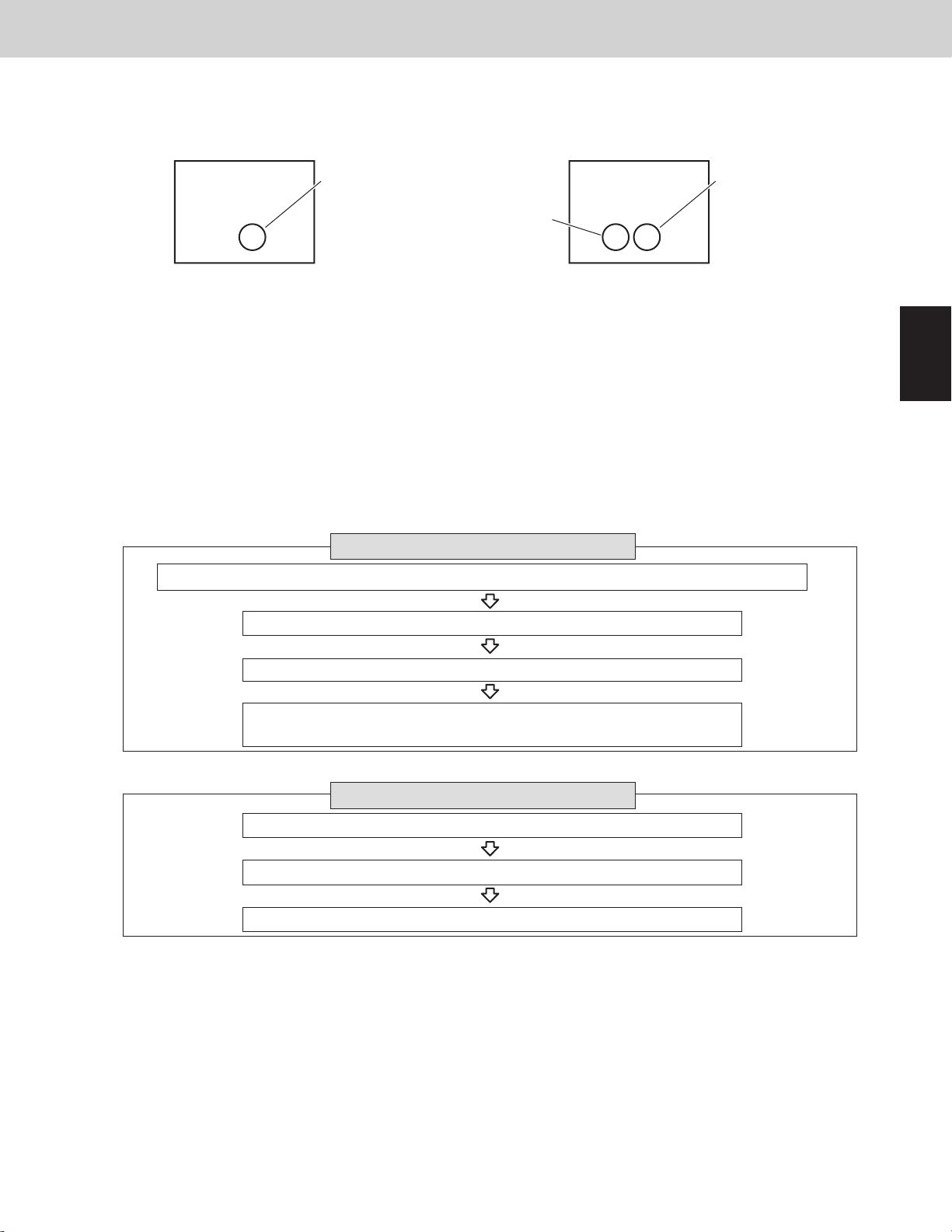
3-1. Compressors Mounted in the Outdoor Units
3-2. Compressor Selection Rules
Placement of compressor seen from the top
3-2-1. Priority order of compressors
A.
A
B
C
D
Decide first priority order of compressor in each outdoor unit.
B. Priority order of compressor trip counter = 0 is higher than that of compressor trip counter = 1.
C. Inverter compressor: Shorter operating time > Longer operating time
D. Compressor that “outdoor unit small address”
installed in outdoor unit
Compressor that “outdoor unit large address”
installed in outdoor unit
First priority order of inverter compressor in each outdoor unit > Other inverter compressor
Compressor trip counter =0 > Compressor trip counter =1
Shorter operating time > Longer operating time
“Outdoor unit small address”
installed in outdoor unit
“Outdoor unit large address”
installed in outdoor unit
>
>
*1
*1 Select first priority order of compressor in each outdoor unit by following method.
The compressor that has no trip counter, shorter operating time and smaller number of compressor will be
taken first priority.
First priority order of inverter compressor in each outdoor unit > Other inverter compressor
2WAY VRF SYSTEM
Control Functions
Type 120, 144
2nd compressor
1st compressor
Front side
Compressor trip counter =0 > Compressor trip counter =1
Shorter operating time > Longer operating time
1st compressor > 2nd compressor
Priority order flow of all compressors
Priority order flow of each outdoor unit
Type 72, 96
Front side
1st compressor
2-3. Outdoor Unit Stop Rules
2-3-1. Stopping of all outdoor units
When all outdoor units must stop, the units stop at the same time.
2-3-2. Stopping of individual outdoor units according to load of air-conditioning
● All cooling mode
3WAY VRF SYSTEM
Control Functions
1
2
3
4
Outdoor air temperature ≥ 113°F (45°C): All outdoor units will be operated. However, there is the outdoor unit
which has the stopped compressor according to load of air-conditioning.
69.8°F (21°C) < outdoor air temperature < 113°F (45°C): the outdoor unit which has the compressor with the
shortest amount of operating time continues to run and rest of the outdoor units may be stopped according to
load air-conditioning.
The outdoor unit which has any compressors without operation may be stopped.
Outdoor air temperature ≤ 69.8°F (21°C): The outdoor unit which has the compressor with the shortest
amount of operating time continues to run and rest of the outdoor units may be stopped according to load airconditioning.
There is the outdoor unit which has only the operating compressor or uses only the heat exchanger with the
stopped compressor according to some conditions.
● All heating mode
The outdoor unit which has the compressor with the shortest amount of operating time continues to run and rest
of the outdoor units may be stopped according to load air-conditioning.
● Mixed cooling/heating
The outdoor unit which has the compressor with the shortest amount of operating time continues to run and rest
of the outdoor units may be stopped according to load air-conditioning.
There is the outdoor unit which has only the operating compressor or uses only the heat exchanger with the
compressor stopped according to some conditions.
5
6
7
8
9
1 - 4
3. Compressor Control
3. Compressor Control
2WAY VRF SYSTEM
Control Functions
3-1. Compressors Mounted in the Outdoor Units
Placement of compressor seen from the top
Type 72, 96
3WAY VRF SYSTEM
Control Functions
Type 120, 144
1st compressor
Front side
3-2. Compressor Selection Rules
3-2-1. Priority order of compressors
A.
Decide first priority order of compressor in each outdoor unit.
The compressor that has no trip counter, shorter operating time and smaller number of compressor will be
taken first priority.
First priority order of inverter compressor in each outdoor unit > Other inverter compressor
B. Priority order of compressor trip counter = 0 is higher than that of compressor trip counter = 1.
C. Inverter compressor: Shorter operating time > Longer operating time
D. Compressor that “outdoor unit small address”
installed in outdoor unit
A
First priority order of inverter compressor in each outdoor unit > Other inverter compressor
B
Compressor trip counter =0 > Compressor trip counter =1
2nd compressor
Front side
Compressor that “outdoor unit large address”
>
installed in outdoor unit
Priority order flow of all compressors
1st compressor
*1
1
2
3
C
D
*1 Select first priority order of compressor in each outdoor unit by following method.
“Outdoor unit small address”
Shorter operating time > Longer operating time
“Outdoor unit large address”
installed in outdoor unit
Priority order flow of each outdoor unit
Compressor trip counter =0 > Compressor trip counter =1
Shorter operating time > Longer operating time
1st compressor > 2nd compressor
>
installed in outdoor unit
4
5
6
7
8
1 - 5
9

1
2WAY VRF SYSTEM
Control Functions
3. Compressor Control
2
3WAY VRF SYSTEM
3. Compressor Control
Control Functions
3-2-2. Operating compressors
When heat exchanger of the outdoor unit is condenser (All cooling mode or mixed cooling/heating)
The compressor with higher priority order starts according to the priority order described on the compressor
selection rules.
Outdoor air temperature<50°F (10°C): More than one compressor among all outdoor units will be operated.
When heat exchanger of the outdoor unit is evaporator (All cooling mode or mixed cooling/heating)
At least, one inverter compressor operates when the system starts.
The other compressors operate according to the priority order described on the compressor selection rules.
3-2-3. Stopping compressors
The compressor with lower priority order starts according to the priority order described on the compressor
selection rules.
3-3. Operation When Starting 2 Compressors Mounted in Outdoor Unit
When necessary capacity gradually increases and one more inverter compressor is additionally started under
the present operating compressor, reduce the compressor frequency to 25Hz temporarily and then start an
additional compressor.
The operation noted above is performed when 1st compressor or 2nd compressor is additionally started.
If necessary capacity is initially higher and two compressors are started simultaneously, the operation noted
above is not performed and both of them are regarded as the target frequency.
3
4
5
6
7
3-4. Operating Frequency Range of Inverter Compressor
The inverter compressor can operate within the range in the table below.
1
When the high pressure is over 435psi (3.0MPa), the upper limit frequency is 90Hz.
If the high pressure is over 450psi (3.1MPa) and the minimum frequency operation is in progress, the system
2
is stopped. (P25: Pre-trip)
If the low pressure is over 213psi (1.47MPa) during operation of the inverter compressor, the system is stopped.
3
(P27: Pre-trip)
If 2 inverter compressors are simultaneously operating in the same outdoor unit, the frequency of 1st
4
compressor becomes 5Hz lower than that of 2nd compressor.
Type of outdoor unit
Minimum frequency (Hz)
Maximum frequency (Hz) 80
The frequency range in the table above is subject to change without notice.*
3-5. Forced Stopping of Compressor
Once a compressor stops, it will not start for a period of 3 minutes (3-minute forced OFF).
However, this does not apply when the compressor was forced to stop as the result of a special control operation.
(start control, defrost control, refrigerant oil recovery control, etc.)
72 96 120 144
15 15 15
100
15
80
80
8
9
1 - 6
3WAY VRF SYSTEM
3. Compressor Control
3-6. Capacity Control (Roadmap control)
1 The capacity control by the compressors is performed according to the pressure sensor attached to the outdoor
unit and temperature thermistor attached to the indoor / outdoor unit heat exchanger.
* With roadmap control, the pressure detected by the pressure sensor is converted to saturation temperature
before it is used by microcomputer. This converted temperature is called “pressure sensor temperature”.
2 This control is performed every 30 seconds.
3 Required level of each indoor unit
Required level of indoor unit is calculated by difference between preset temperature in remote controller and
intake temperature of indoor unit (TA), difference between preset discharge air temperature in EEPROM on
indoor unit PCB and discharge air temperature of indoor unit (TF).
Required level has “0” to “30” phases. This level becomes “31” at the test run.
The target temperature of indoor unit heat exchanger is decided according to the maximum required level.
* Target temperature of all indoor units heat exchanger is same value because all indoor units are connected
with the same pressure piping.
4 Denition of evaporation temperature and condensation temperature
● Evaporation temperature (Te):
Shows the lowest temperature among the temperature sensors (E1 or E3) when the indoor unit heat exchanger
is functioning as an evaporator.
* When operating in mixed cooling/heating mode and the outdoor units are mixed evaporators, the outdoor unit
heat exchanger temperature is not recognized as “Te”.
● Condensation temperature (Tc):
Shows the highest temperature among the high-pressure saturated temperature in the system and indoor unit
heat exchanger’s liquid tube temperature (E1) with the thermostat ON.
Control Functions
1
2
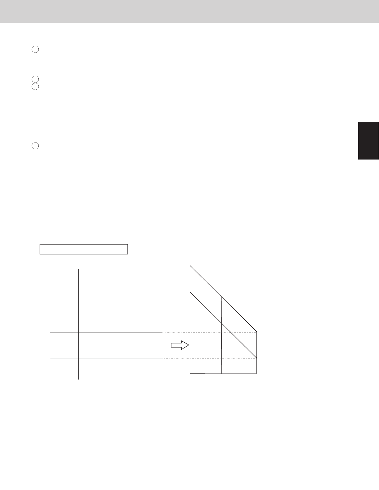
3-6-1. Evaporation temperature adjustment by roadmap control
The cooling capacity is adjusted with this control. It prevents freezing of the indoor unit's heat exchanger and the
dew to the outside panel of the indoor unit. The capacity is adjusted according to the following gure.
Evaporation temperature area
deg
Compressor capacity increase possible
43.0 (6.1)
42.8 (6.0)
37.4 (3.0)
37.2 (2.9)
* The evaporation temperature area changes depending on the maximum required level of each indoor unit as
shown above.
* Area C is regarded as area B for 6 minutes after compressor starts.
* When the system operates in a minimum capacity, the system will continue operating for at least 6 minutes if the
evaporation temperature area is area C.
* The evaporation temperature is not adjusted while specially controlling defrosting and the oil recovery, etc.
* The evaporation temperature is not adjusted when there are one or more indoor units that select the test run.
If one or more indoor units are selected into test run, the system doesn't stop in all states except alarm appearing.
* The test run will nish automatically in about one hour.
Compressor capacity
increase prohibited
Compressor capacity decrease
60.8 (16.0)
55.4 (13.0)
Area A
Area B
Area C
51.8 (11.0)
46.4 (8.0)
0
Max. required level
15
unit: °F (°C)
42.8 (6.0)
37.4 (3.0)
30
3
4
5
6
7
8
1 - 7
9
1
2
3
4
3WAY VRF SYSTEM
3. Compressor Control
3-6-2. Condensation temperature adjustment by roadmap control
The area B target temperature is different due to cooling, heating and mixed cooling/heating operation.
Target lower temperature
(Tc_tgt_min)
Cooling 127.4°F (53.0°C) 131.0°F (55.0°C)
Heating 118.4°F (48.0°C) 123.8°F (51.0°C)
Mixed cooling/heating 118.4°F (48.0°C) 123.8°F (51.0°C)
Cooling mode
1
The purpose of this control at cooling
is to prevent abnormal high-pressure.
・Standard setting (at the shipment)
°F (°C) °F (°C)
PX=136.4
(58.0)
136.2
(57.9)
131.2
(55.1)
131.0
(55.0)
127.4
(53.0)
127.2
(52.9)
Thermostat
OFF
Compressor
capacity
decrease
Compressor
capacity
increase
prohibited
Compressor
capacity
increase
possible
Area D
Area C
Area B
Area A
Heating mode and mixed cooling/heating mode
2
Heating capacity is adjusted with this control.
It also prevents abnormal high-pressure simultaneously.
The capacity is controlled in the following diagram.
PX=136.4
(58.0)
136.2
(57.9)
124.0
(51.1)
123.8
(51.0)
118.4
(48.0)
118.2
(47.9)
Target upper temperature
(Tc_tgt_max)
Thermostat
OFF
Compressor
capacity
decrease
Compressor
capacity
increase
prohibited
Compressor
capacity
increase
possible
Area D
Area C
Area B
Area A
95.0
(35.0)
109.4
(43.0)
Control Functions
104.9
(40.5)
°F (°C)
123.8
(51.0)
118.4
(48.0)
5
6
7
8
91.4
(33.0)
15 300
Max. required level
* PX is usually xed to 136.4°F (58°C). If the high pressure goes up rapidly after the compressor starts, the
system experiences urgent stop. The next time the system will start with lower PX.
* In the area B, the compressor capacity changes depending on the refrigerant condition.
* When the system operates in a minimum capacity, the system will continue operating for at least 6 minutes
if the condensation temperature area is area C.
* The condensation temperature is not adjusted when there are one or more indoor units that select the test run.
Limit pressure adjustment function
Operation pressure is able to be adjusted for existing old piping.
If area shift function is set, values below shift.
EEPROM setting in main outdoor unit
CODE : 4B
Setting No. Limited pressure PX °F (°C) Cooling mode
Tc_tgt_min Tc_tgt_max Tc_tgt_min Tc_tgt_max
0 478.5psi (3.3MPa) 126.5 (52.5) 116.6 (47.0) 120.2 (49.0) 116.6 (47.0) 118.4 (48.0)
1 No use - - - - 2 551.1psi (3.8MPa) 136.4 (58.0) 127.4 (53.0) 131.0 (55.0) 118.4 (48.0) 123.8 (51.0)
3 No use - - - - -
Heating mode and mixed
cooling/heating mode
9
1 - 8
3WAY VRF SYSTEM
3. Compressor Control
3-6-3. Cooling operation with low ambient temperature
When operating in cooling mode with the ambient temperature less than 69.8°F (21°C), the unit is set in low
ambient temperature cooling mode.
During low ambient temperature cooling mode, the heat exchanger capacity control is performed in addition to the
compressor capacity control. The target condensation temperature (Tc_tgt) is controlled between 73.4°F ~ 77°F
(23°C ~ 25°C).
Thereof, the heat exchanger may sometimes be used by half even if the operation is cooling in all indoor units.
(1) Capacity changes of compressor
Similar to control normal cooling operation
(2) Capacity changes of heat exchanger
* Condensation temperature (Tc) is high
The outdoor heat exchanger capacity is increased, increasing the system condensation capacity and lowering the
condensation temperature (Tc).
* Condensation temperature (Tc) is low
The outdoor heat exchanger capacity is decreased, decreasing the system condensation capacity and raising the
condensation temperature (Tc).
Outdoor Unit Heat Exchanger Control Table
Low ← Condensation Temp. [Tc] → High
A C
B D
Control Functions
1
2
91.4°F
87.8°F
(31°C)
83.3°F
(28.5°C)
57.2°F (14°C)
A
51.8°F (11°C)
42.8°F (6°C)
B
37.4°F (3°C)
C
26.6°F (-3°C)
Low←Evaporation Temp. [ Te ]→High
3-6-4. Control of condensation temperature and evaporation temperature during mixed cooling/heating operation
During mixed cooling/heating operation, the control maintains a heat balance with a target evaporation temperature
(Te) for the cooling mode indoor units of 37.4°F ~ 42.8°F (3°C ~ 6°C) and a target condensation temperature (Tc)
for the heating mode indoor units of 118.4°F ~ 123.8°F (48°C ~ 51°C).
Heat balance control is performed by varying the compressor capacity and heat discharge (heat intake) of the heat
exchanger.
(1) Increasing/decreasing the compressor capacity
* When evaporation temperature (Te) is high and condensation temperature (Tc) is low.
This occurs when both the cooling capacity (heat intake) and the heating capacity (heat discharge) are low.
The compressor capacity and the circulation ow of refrigerant are increased in order to lower the evaporation
temperature (Te) and raise the condensation temperature (Tc).
* When evaporation temperature (Te) is low and condensation temperature (Tc) is high
This occurs when both the cooling capacity (heat intake) and the heating capacity (heat discharge) are high.
The compressor capacity and the circulation ow of refrigerant are decreased in order to raise the evaporation
temperature (Te) and lower the condensation temperature (Tc).
* Under conditions other than those listed above, the capacity of the outdoor unit heat exchanger is adjusted.
In some cases the heat exchanger capacity may also be adjusted at the same time when the compressor capacity
is varied.
89.6°F
(32°C)
(33°C)
95°F
1 - 9
(35°C)
100.58°F
100.4°F
(38°C)
(38.1°C)
101.48°F
UPDOWN STAY
136.4°F
(38.6°C)
(58°C)
Compressor stop
3
4
5
6
7
8
9
Compressor Control Table
ABCD
3. Compressor Control
Low Condensation Temp. [Tc] High
3WAY VRF SYSTEM
Control Functions
1
2
3
4
A
B
C not_UP
Low Evaporation Temp. [Te] High
Evaporation temperature (Te) and condensation temperature (Tc) areas A, B, C and D are the same as for
evaporation temperature control and condensation temperature control.
(2) Increasing/decreasing the heat exchanger capacity (when the outdoor unit heat exchanger is functioning as a
condenser)
• Primarily when both the evaporation temperature (Te) and condensation temperature (Tc) are high
This occurs when the cooling capacity (heat intake) is low and the heating capacity (heat discharge) is high.
The outdoor heat exchanger capacity is increased, increasing the system condensation capacity and lowering
the condensation temperature (Tc). The amount of heat discharge at the outdoor unit heat exchanger is
increased, increasing the heat intake at the cooling mode indoor units and lowering the evaporation
temperature (Te).
• Primarily when both the evaporation temperature (Te) and condensation temperature (Tc) are low
This occurs when the cooling capacity (heat intake) is high and the heating capacity (heat discharge) is low.
The outdoor heat exchanger capacity is decreased, decreasing the system condensation capacity and raising
the condensation temperature (Tc). The amount of heat discharge at the outdoor unit heat exchanger is
decreased, decreasing the heat intake at the cooling mode indoor units and raising the evaporation
temperature (Te).
UP
slow_UP Target
not_UP
STOP
DOWN
5
6
Outdoor Unit Heat Exchanger Control Table (when the outdoor unit heat exchanger is functioning as a
condenser)
A
7
42.8°F (6°C)
B
37.4°F (3°C)
8
C
26.6°F (-3°C)
Low←Evaporation Temp. [ Te ]→High
9
32°F (0°C)
Low ← Condensation Temp. [Tc] → High
A C
110.3°F
(43.5°C)
114.8°F
(46°C)
STAY
DOWN
B D
123.8°F
(51°C)
118.4°F
(48°C)
UP
Target
1 - 10
136.4°F
(58°C)
Compressor stop
3WAY VRF SYSTEM
3. Compressor Control
(3) Increasing/decreasing the heat exchanger capacity (when the outdoor unit heat exchanger is functioning as an
evaporator)
• Primarily when both the evaporation temperature (Te) and condensation temperature (Tc) are low
This occurs when the cooling capacity (heat intake) is high and the heating capacity (heat discharge) is low.
The outdoor heat exchanger capacity is increased, increasing the system evaporation capacity and raising
the evaporation temperature (Te). The amount of heat intake at the outdoor unit heat exchanger is increased,
increasing the heat discharge at the heating mode indoor units and raising the condensation temperature (Tc).
• Primarily when both the evaporation temperature (Te) and condensation temperature (Tc) are high
This occurs when the cooling capacity (heat intake) is low and the heating capacity (heat discharge) is high.
The outdoor heat exchanger capacity is decreased, decreasing the system evaporation capacity and lowering
the evaporation temperature (Te). The amount of heat intake at the outdoor unit heat exchanger is
decreased, decreasing the heat discharge at the heating mode indoor units and lowering the condensation
temperature (Tc).
Outdoor Heat Exchanger Control Table (when the outdoor heat exchanger is functioning as an evaporator)
Low ← Condensation Temp. [Tc] → High
A C
B D
127.4°F
(53°C)
129.2°F
(54°C)
130.1°F
118.4°F
(48°C)
123.8°F
(51°C)
(54.5°C)
Control Functions
136.4°F
(58°C)
1
2
A
42.8°F (6°C)
B
37.4°F (3°C)
STAY
UP
30.2°F (-1°C)
C
26.6°F (-3°C)
24.8°F (-4°C)
Low←Evaporation Temp. [ Te ]→High
DOWN
Target
STA Y
Compressor stop
3-7. Protection Control
3-7-1. Compressor discharge temperature protection
The compressor capacity is controlled according to the table below.
*Discharge temperature that is used for this control is the highest temperature among all compressors.
Discharge temp.
°F (°C)
222.8
(106)
221.0 (105)
219.2 (104)
217.4 (103)
213.8 (101)
3-7-2. Abnormal low pressure protection
The compressor capacity is controlled according to the table below.
Low pressure
psi (MPa)
36.3 (0.25)
29.0 (0.20)
24.7 (0.17)
Stop
If this temperature is detected at regular intervals, alarm appears.
Compressor
capacity
decrease
Compressor capacity increase prohibited
Compressor capacity increase possible
No restriction
Capacity goes up slowly
Capacity increase prohibited
Capacity goes down
Capacity goes down 2.0 hp
Capacity goes down 1.0 hp
Capacity goes down 0.5 hp
1 - 11
hp = horsepower
3
4
5
6
7
8
9
2WAY VRF SYSTEM
Control Functions
3. Compressor Control
2WAY VRF SYSTEM
Control Functions
3. Compressor Control
Inverter layout
Noise
filter
R
S
T
U
V
W
U
V
W
U
V
W
R
S
T
Power
supply
Primary CT1
Primary CT2
Secondary CT1
Secondary CT2
Diode
bridge
IPM (CM)
1st compressor
Fan motor
U-72MF2U94 / U-96MF2U94 / U-120MF2U94 / U-144MF2U94
Use the same values of 1st compressor and 2nd compressor.
unit: Ampere
Current limit 1
Maximum current 1 H
Primary
Maximum current 1 L 15.5
19.5 19.5 19.5 19.5
72 96 120 144
15.5
16.5
15.5
16.5 16.5 16.5
15.5
Current limit 2
Maximum current 2 H
Secondary
Maximum current 2 L 13.1
16.6 23.0 16.6 16.6
19.5
14.1
13.1
14.1 20.5 14.1
13.1
Type of outdoor unit
Noise
filter
Diode
bridge
IPM (CM)
IPM (FN)
2nd compressor
3. Compressor Control
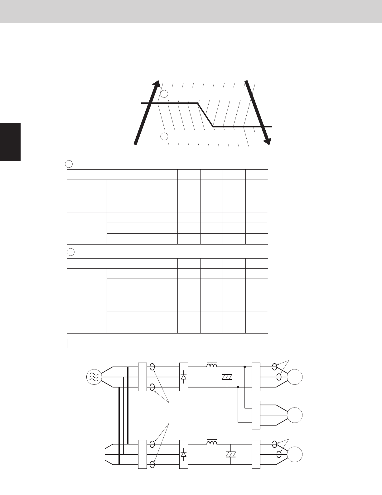
3-7-3. Current protection
This restriction protects the compressor and controls the compressor electric current simultaneously.
The current limitation value changes to “normal status” and “overload status” according to the outdoor
temperature.
The primary and secondary current values of 1st compressor and 2nd compressor are measured.
3WAY VRF SYSTEM
Control Functions
1
2
3
4
Outdoor temperature
U-72MF2U9 / U-96MF2U9 / U-120MF2U9 / U-144MF2U9
A Normal status: Use the same values of 1st compressor and 2nd compressor.
Primary
Secondary
Overload status: Use the same values of 1st compressor and 2nd compressor.
B
114.8°F (46°C)
Type of outdoor unit
Type of outdoor unit
Current limit 1
Maximum current 1 H
Maximum current 1 L24
Current limit 2
Maximum current 2 H
Maximum current 2 L24
Current limit 1
B
A
Current table <Overload>
Current table <Normal>
72 96 120 144
30 43 30 30
25 38 22.5
30 44 30 30
25 40 25
72 96 120 144
30 43 30 30
37
39
22.5
21.5
25
24
21.5
24
Outdoor temperature
109.4°F (43°C)
unit: Ampere
unit: Ampere
5
6
7
8
Primary
Secondary
Inverter layout
Power
supply
R
S
T
Maximum current 1 H
Maximum current 1 L24
Current limit 2
Maximum current 2 H
Maximum current 2 L24
R
S
T
Noise
Noise
filter
Primary CT1
Primary CT2
filter
25 38 21
30 44 30 30
25 40 23
Diode
bridge
Diode
bridge
37
39
21
20
23
22
20
22
IPM (CM)
U
V
W
IPM (FN)
U
V
W
IPM (CM)
U
V
W
Secondary CT1
1st compressor
Fan motor
Secondary CT2
2nd compressor
9
1 - 12
2WAY VRF SYSTEM
Control Functions
3. Compressor Control
3. Compressor Control
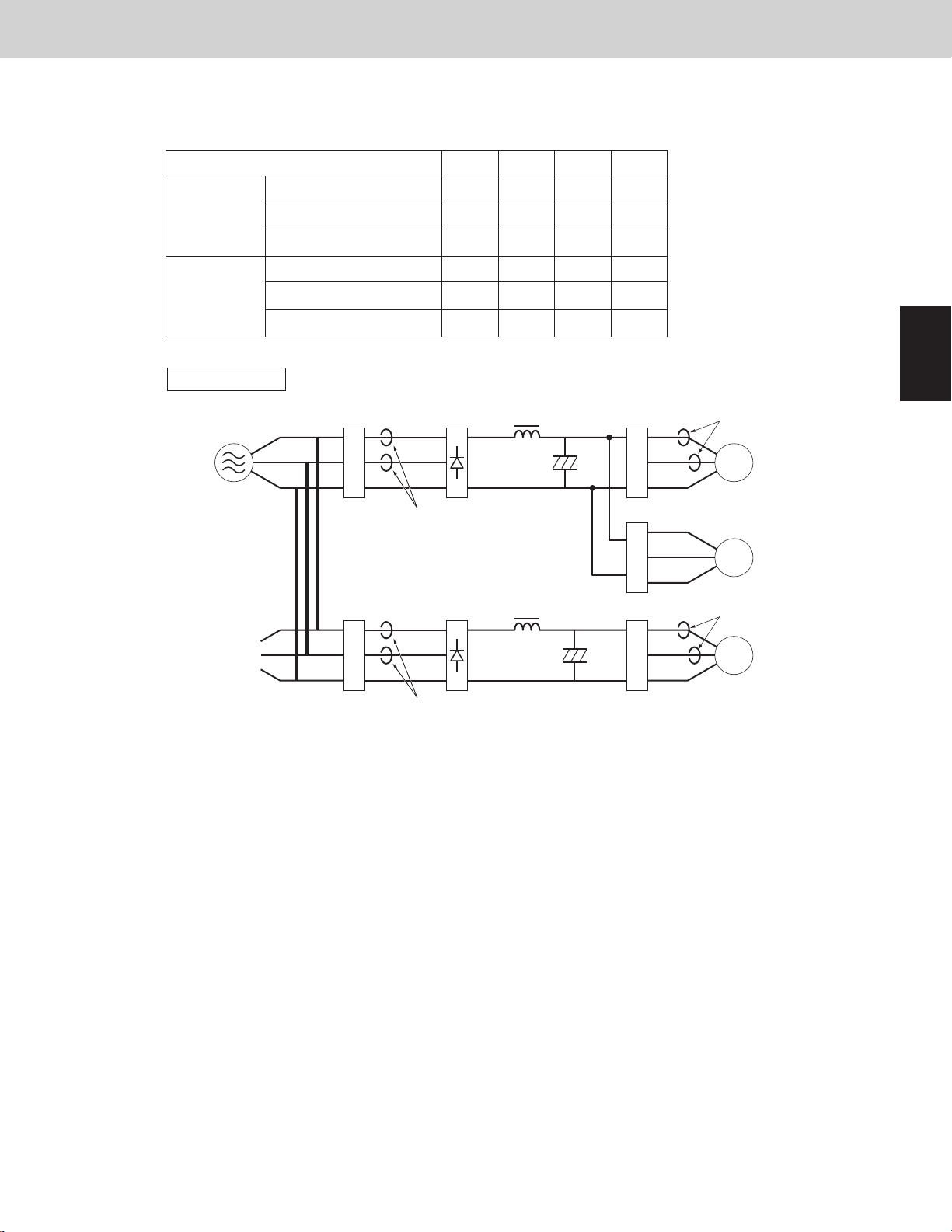
U-72MF2U94 / U-96MF2U94 / U-120MF2U94 / U-144MF2U94
Use the same values of 1st compressor and 2nd compressor.
Type of outdoor unit
Current limit 1
72 96 120 144
19.5 19.5 19.5 19.5
3WAY VRF SYSTEM
Control Functions
unit: Ampere
Primary
Secondary
Inverter layout
Power
supply
R
S
T
Maximum current 1 H
Maximum current 1 L 15.5
Current limit 2
Maximum current 2 H
Maximum current 2 L 13.1
Noise
filter
R
S
T
Primary CT1
Noise
filter
16.5 16.5 16.5
16.6 23.0 16.6 16.6
14.1 20.5 14.1
Diode
bridge
Diode
bridge
15.5
19.5
16.5
15.5
14.1
13.1
15.5
13.1
IPM (CM)
U
V
W
IPM (FN)
U
V
W
IPM (CM)
U
V
W
Secondary CT1
1st compressor
Fan motor
Secondary CT2
2nd compressor
1
2
3
4
Primary CT2
5
6
7
8
1 - 13
9

1
2
4. Output of PCB
Item Indication on PCB
Solenoid valve
Expansion valve
Crankcase heater
3WAY VRF SYSTEM
Control Functions
Discharge valve 1 DCV1
Discharge valve 2 DCV2
Suction valve 1 SCV1
Suction valve 2 SCV2
Heat exchanger pressure balance valve 1 PBV1
Heat exchanger pressure balance valve 2 PBV2
Save valve SAVE
Refrigerant control valve RCV
Refrigerant balance valve RBV
Oil recovery valve ORVR
By-pass valve BPV
Accumulator valve ACV
2
O
valve O2
MOV for heat exchanger 1 MOV1
MOV for heat exchanger 2 MOV2
SC circuit expansion valve MOV4
Crankcase heater control 1 CH1
Crankcase heater control 2 CH2
3
4
5
6
7
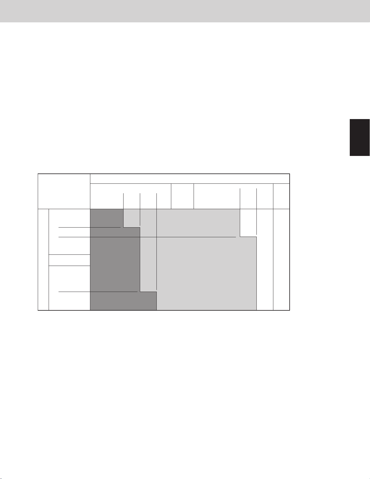
4-1. [DCV, SCV, PBV]
Turn DCV, SCV and PBV to ON/OFF.
Change the outdoor unit heat exchanger mode and/or control the heat exchanger capacity.
See the basic operation listed below.
All
cooling
mode
All
heating
mode
Mixed
cooling/
heating
mode
Status of
heat exchanger
Normal Condenser ON ON OFF OFF OFF OFF
Low ambient
temperature
System stopped
Other outdoor *2
units operating
Heat exchanger
[condenser] of
outdoor unit
Heat exchanger
[evaporator] of
outdoor unit
Condenser ON/OFF ON OFF OFF OFF OFF
Stop OFF OFF OFF OFF OFF OFF
Evaporator ON ON ON ON ON ON
*1
Stop OFF OFF OFF OFF OFF OFF
Stop ON ON ON ON ON ON
Condenser ON/OFF ON OFF OFF OFF OFF
Stop OFF OFF OFF OFF OFF OFF
Evaporator ON/OFF ON ON/OFF ON ON/OFF ON
Stop OFF OFF OFF OFF OFF OFF
DCV1
*3
DCV2 SCV1
*3
SCV2 PBV1
*3
PBV2
8
9
*1 The system which is stopped in heating mode shows the status of all outdoor units stopped.
*2 When other outdoor units are operating in heating mode, the outdoor unit in stop mode is holding the pulse
at 0 pulses of MOV1 and MOV2 in a situation in which the heat exchanger is evaporator.
*3 DCV1, SCV1 and PBV1 turn ON/OFF respectively due to the capacity control of the heat exchanger.
1 - 14
3WAY VRF SYSTEM
4. Output of PCB
4-2. Save Valve [SAVE]
● This valve turns ON for 5 seconds before the inverter compressor starts.
After the inverter compressor starts, the valve turns ON for 10 seconds. Then it turns OFF.
● This valve turns ON for 30 seconds after the outdoor unit stops. Then it turns OFF.
● This valve turns ON when high pressure sensor detects 496psi (3.42MPa) to prevent abnormal pressure.
This valve turns OFF when the high pressure goes down below 481.5psi (3.32MPa).
● This valve might turn ON when the system capacity is excessive although the inverter compressor operates at
Min. frequency.
● This valve turns ON in the following status :
(Compressor discharge temperature - High pressure saturation temperature) < 9deg F (5deg C)
● Under control of Tube Refrigerant Recovery Control
● Under control of heat exchanger select mode
● This valve turns ON when low pressure sensor goes down 24.7psi (0.17MPa) to prevent abnormal pressure.
This valve turns OFF when low pressure sensor increase 29psi (0.20MPa) or over.
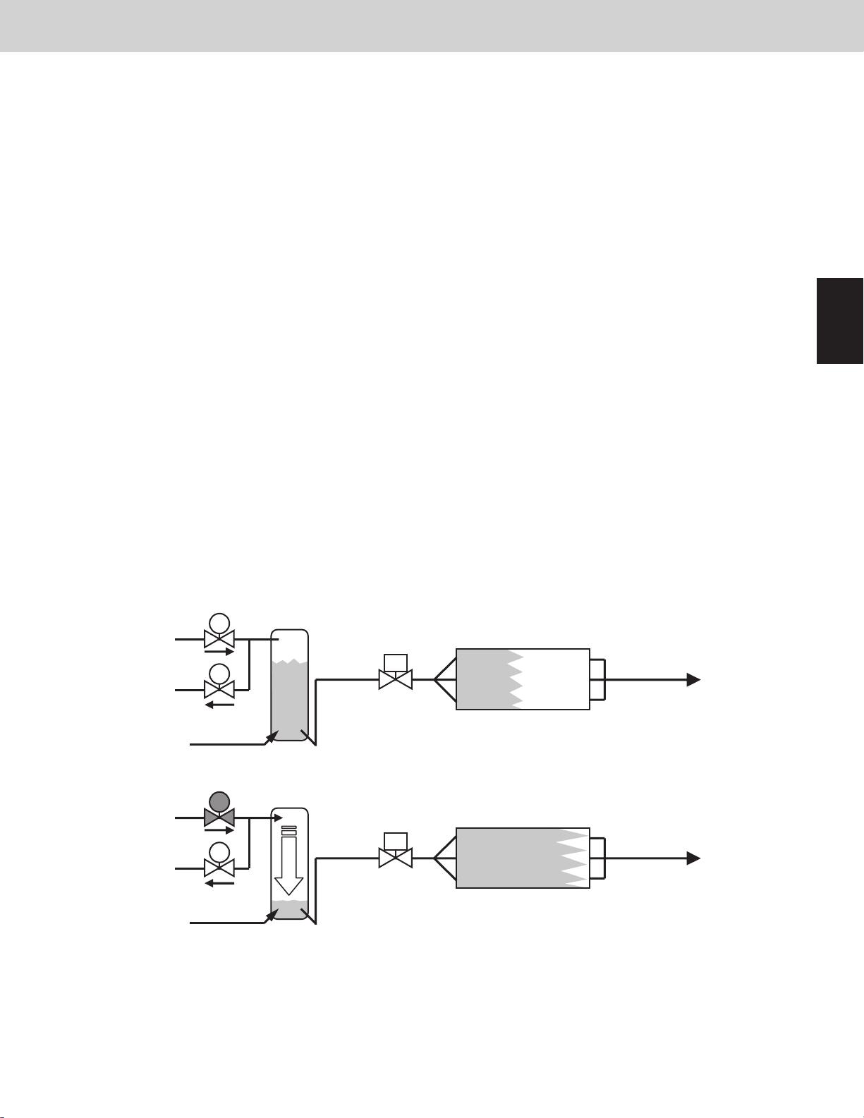
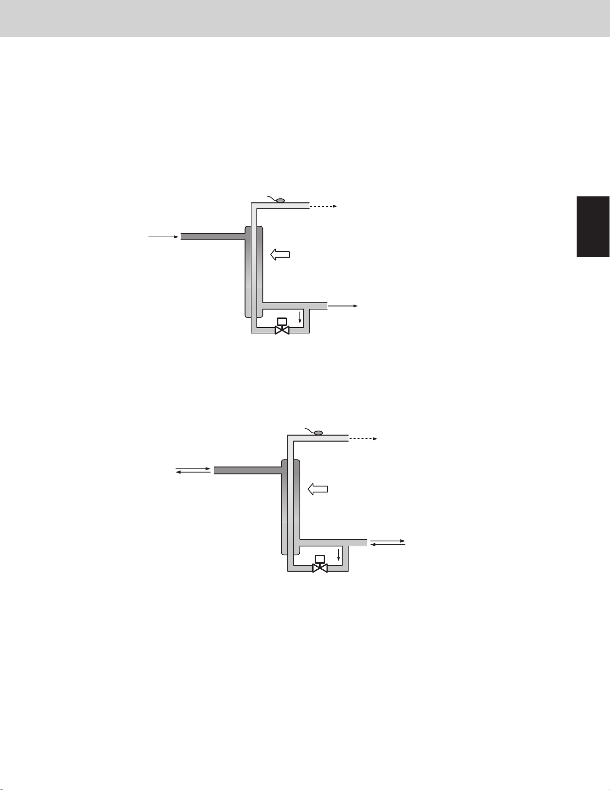
4-3. Refrigerant Control Valve [RCV]
The main purpose of this valve is to detect the ow of refrigerant (refrigerant volume) on the indoor unit when the
outdoor unit heat exchanger is functioning as a condenser. When the valve determines that there are signs of a low
refrigerant level, refrigerant is supplied from the receiver tank to the system.
● This valve turns ON when the evaporator is refrigerant shortage.
The heat exchanger of indoor unit is evaporator in cooling operation.
The heat exchanger of outdoor unit is evaporator in heating operation.
● This valve turns OFF when the excessive refrigerant is in the condenser.
The heat exchanger of indoor unit is condenser in heating operation.
The heat exchanger of outdoor unit is condenser in cooling operation.
● This valve turns OFF when the outdoor unit is stopped.
● This valve turns ON at stopped outdoor units when the heat exchanger at another outdoor unit is functioning as a
condenser.
Control Functions
1
2
3
HP
LP
HP
LP
RCV
RBV
RCV
RBV
Evaporator
Two-phase
flow
Refrigerant shortage in evaporator
Receiver tank holds refrigerant
ON
Evaporator
Two-phase flow
Sufficient refrigerant is supplied to evaporator
High pressure from RCV pushes the liquid refrigerant out of the receiver tank
4
5
6
7
8
1 - 15
9
1
2
3WAY VRF SYSTEM
4. Output of PCB
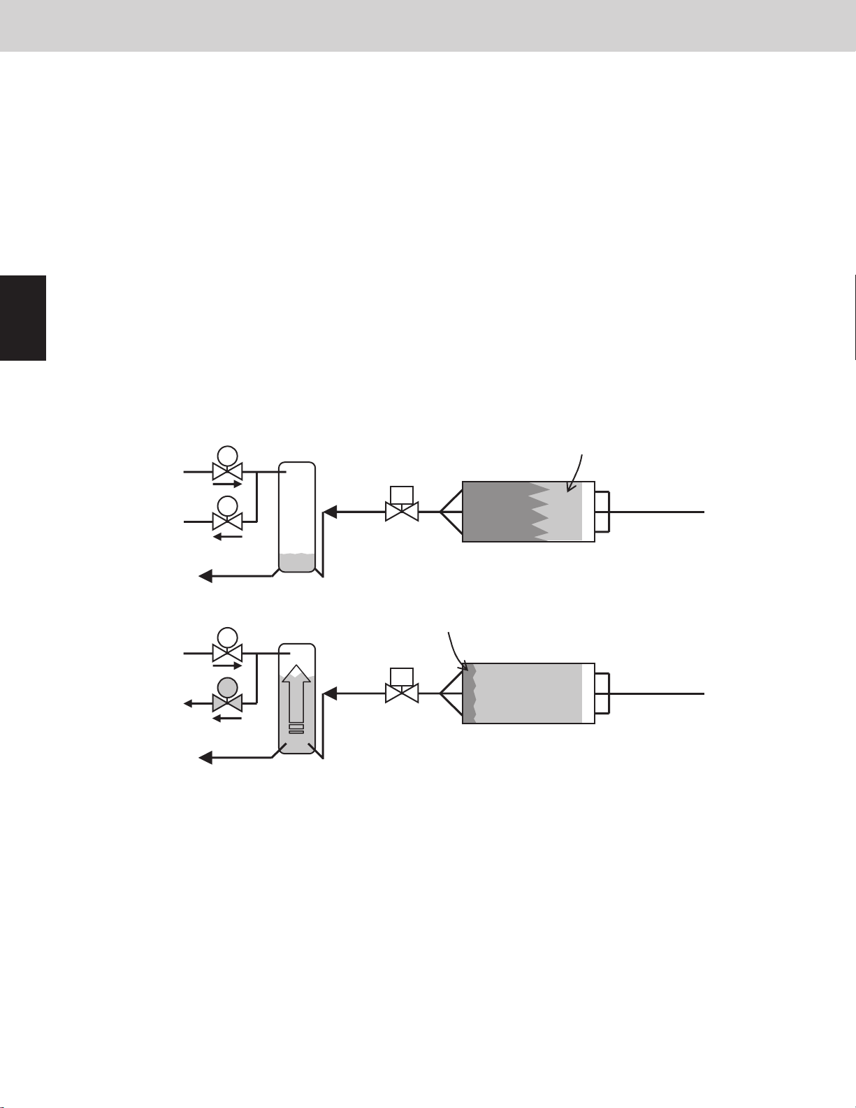
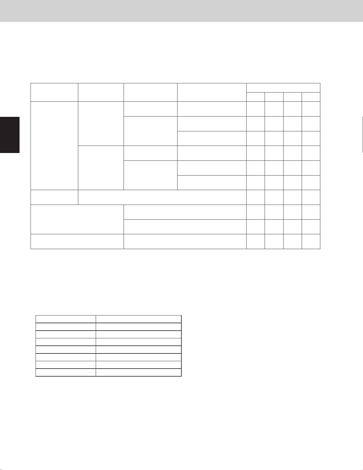
4-4. Refrigerant Balance Valve [RBV]
The main purpose of this valve is to detect the ow of refrigerant (refrigerant volume) on the indoor unit when the
outdoor unit heat exchanger is functioning as an evaporator.
When the valve determines that there are signs of excess refrigerant, refrigerant is recovered at the receiver tank.
This valve is ON during heating operation and when the outdoor unit heat exchanger is functioning as an
evaporator during mixed heating/cooling operation. It also turns ON in order to recover refrigerant at the outdoor
unit after heating operation is stopped.
* This valve is never ON at the same time as the RCV.
● This valve turns ON for 20 seconds after the system stops at heating mode, and then turns OFF.
● This valve turns ON once after the system starts at heating mode.
● This valve turns OFF when an abnormal drop in compressor discharge gas temperature is detected.
● This valve turns OFF when liquid back to the compressor is occurring.
Judgment of liquid back:
Detected suction temperature is lower than low-pressure sensor temperature.
Difference between high-pressure sensor temperature and discharge temperature of compressor is small.
(less than 9deg F (5deg C))
* After the valve turns from ON to OFF, it will not turn ON again for 15 minutes.
● This valve turns ON when low pressure sensor decreases 24.7psi (0.17MPa) at stopped system.
This valve turns OFF when low pressure sensor increases 29psi (0.20MPa).
Two-phase flow
HP
RCV
Condenser
Control Functions
3
4
5
6
7
8
RBV
LP
Receiver tank holds small amount of refrigerant
Liquid flow
RCV
HP
RBV
LP
ON
Refrigerant gas in the top of receiver tank is pulled into low pressure side.
4-5. Oil Recovery Valve [ORVR]
This valve is for recovering oil from the oil separator of its own outdoor unit or balance tube to the compressor of
its own outdoor unit.
● This valve turns ON when the oil level of the compressor is “0” or “1”.
In this situation, system performs Self oil recovery control, Inter-outdoor unit oil recovery control, or system oil
recovery control.
● This valve turns ON for 2 minutes after the compressor starts.
● This valve is always OFF when outdoor unit is stopped.
* For oil level of compressor, see “Oil Control” section.
Liquid
flow
Over charge condition
Condenser
Two-phase flow
Adequate condition
9
1 - 16

3WAY VRF SYSTEM
4. Output of PCB
4-6. By-Pass Valve [BPV]
This valve is for pushing the oil in the balance piping into other outdoor unit.
● This valve turns ON when the oil level of compressor is “2” or “1” in its own outdoor unit and the oil level of
compressor is “0” in other outdoor unit.
* This valve turns ON for 10 seconds and turns OFF for 20 seconds. This operation is repeated while oil is
supplied to others.
* For more information on oil level of compressor, see “Oil Control” section.
4-7. Accumulator Valve [ACV]
The purpose of this valve is to recover oil and refrigerant from the accumulator to the compressor.
● This valve turns OFF when the compressor operation just started.
● This valve turns ON when the compressor is warmed up.
● This valve turns ON while the oil recovery among the systems and defrost control are in progress.
● This valve turns ON while the MOV4 is operating.
Control Functions
1
4-8. O2 Valve [O2*]
This valve works when the outdoor unit receives signal of the refrigerant leakage from the indoor unit.
The indoor unit that transmits the signal of the refrigerant leakage gives “P14”alarm.
To activate this function, it is necessary to set it to EEPROM on the main outdoor PCB and indoor PCB.
EEPROM setting in main noutdoor unit
CODE: C1
Setting No.
0 This function invalid (factory preset mode)
1
2
EEPROM setting in indoor unit
CODE: 0B
Setting No.
0 Function of EXCT plug short-circuit
1 Indoor unit gives “P14”alarm and transmits the refrigerant leakage signal.
4-9. MOV for Heat Exchanger [MOV1, MOV2]
4-9-1. Type of expansion valves
This valve is turned OFF when the system is normal.
This valve is turned ON when the outdoor unit receives signal from the indoor unit.
This valve is turned ON when the system is normal.
This valve is turned OFF when the outdoor unit receives signal from the indoor unit.
MOV1 For upper side heat exchanger
MOV2 For lower side heat exchanger
*O2 valve is the eld supply parts.
2
3
4
5
6
4-9-2. Power Initialization
If no indoor units have started (even once) after the power supply to the outdoor unit, the MOV for heat exchanger
holds the pulse at 480 pulses.
1 - 17
7
8
9
3WAY VRF SYSTEM
4. Output of PCB
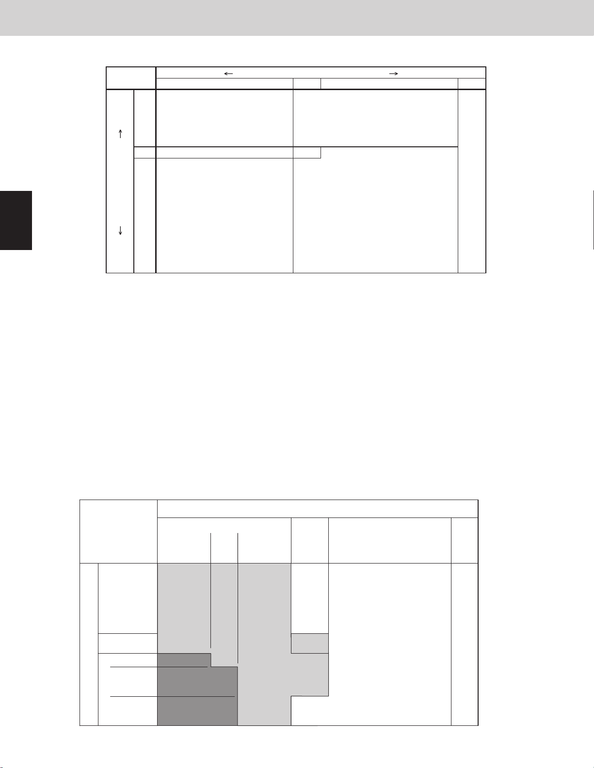
4-9-3. Expansion valves for heat exchanger control
The conguration of the heat exchangers is different depending on the capacity of the outdoor unit.
Operation of electronic control valves during normal unit operation
All
cooling
mode
Status of
heat exchanger
Normal Condenser 480 480 Maximum ow control
Low ambient
temperature
Condenser 0 ~ 480 0 ~ 480 Heat exchanger capacity control
Stop 0 0 Refrigerant shut-off
MOV1 MOV2 Remarks
Control Functions
1
2
3
4
5
6
Evaporator 12 ~ 480 12 ~ 480 SH control
All
heating
mode
Mixed
cooling/
heating
mode
When operating in all cooling or all heating mode, the heat exchangers of which the compressors are driving in the
outdoor units are used.
However, when operating in cooling mode with low ambient temperature, the number of pieces for using the heat
exchanger is changed according to the operating condition of indoor units and the status of outdoor units.
When operating in mixed cooling/heating mode, the condition and the number of pieces for using the heat
exchanger are changed according to the operating condition of indoor units and the status of outdoor units.
The heat exchanger is selected in turn from the outdoor unit 2nd heat exchanger as the shortest operating time of
the inverter compressor.
SH control is controlled so that the difference of temperature between the liquid tube temperature and gas tube
temperature should be set within the range as shown below.
Mixed cooling/heating mode (Heat exchanger [evaporator] of outdoor unit) 3.6deg F ~ 9deg F (2deg C ~ 5deg C)
System stopped Stop 0 0 Refrigerant shut-off
Other outdoor
units operating
Heat exchanger
[condenser] of
outdoor unit
Heat exchanger
[evaporator] of
outdoor unit
Stop 0 0 Refrigerant shut-off
Condenser 0 ~ 480 0 ~ 480 Heat exchanger capacity control
Stop 0 0 Refrigerant shut-off
Evaporator 12 ~ 480 12 ~ 480 SH control
Stop 0 0 Refrigerant shut-off
Outdoor unit Capacity Target value of SH control
All heating mode -1.8deg F ~ 9deg F (-1deg C ~ 5deg C)
7
8
9
1 - 18
3WAY VRF SYSTEM
4. Output of PCB
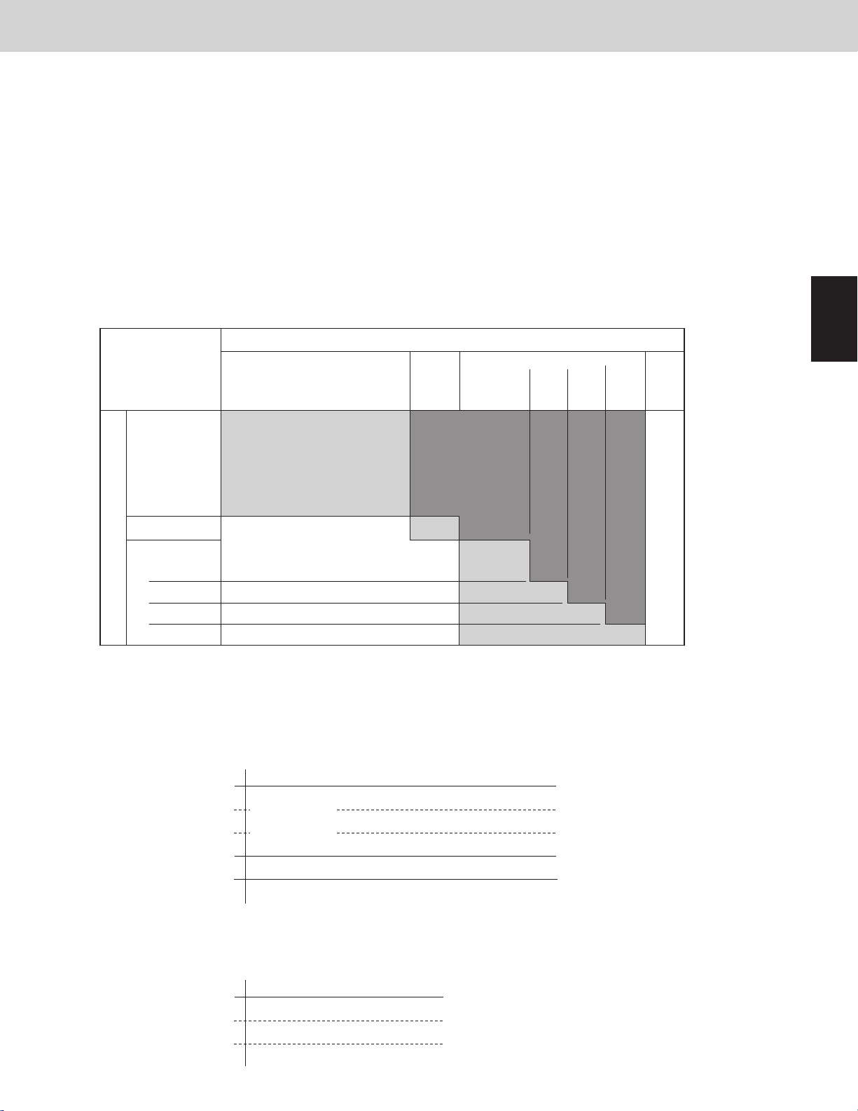
4-10. SC Circuit Expansion Valve [MOV4]
4-10-1. SC control (Cooling mode only)
During cooling operation, the liquid refrigerant which condenses at the outdoor unit heat exchanger ows into
the receiver tank, and SC (sub-cooling) approaches 32°F (0°C). When SC is small and the length of the tubing
connecting the indoor and outdoor units is long, the refrigerant ow in the indoor unit will be reduced signicantly.
To prevent this trouble from occurring, MOV4 operates so as to increase supercooling in the double tube coil near
the outlet of the outdoor unit.
In addition, MOV4 controls refrigerant ow volume so that it will not ow back to the compressor in the liquid state.
SH in suction that is difference between the SCG temperature and low pressure sensor temperature is adjusted to
5.4deg F ~ 9deg F (3deg C ~ 5deg C).
SCG
Gas returns to
accumulator
Control Functions
Liquid
(SC=0deg)
(SH control)
4-10-2. Discharge temperature control of compressor
When the discharge temperature increases to 194°F (90°C) or more, MOV4 opens to 100 pulses to cool down the
compressor. MOV4 operates according to the state of the discharge temperature between 20 - 480 pulses. This
operation takes priority over SC control.
Liquid
Refrigerant on the inner side evaporates,
cooling the liquid refrigerant on the outer side.
Liquid
(Large SC)
MOV4
SCG
Does not fully evaporate,
resulting in liquid backup.
Liquid returns to
accumulator
1
2
3
4
5
Liquid
MOV4
(Discharge temperature control of compressor.)
This operation is continued until discharge temperature decreases to 176°F (80°C) or less.
4-10-3. Discharge temperature and high pressure control in outdoor unit cycle defrost control
When outdoor unit cycle defrost control operates, MOV4 opens to 200 pulses or over.
4-11. Crankcase Heater Control [CH1, CH2]
When the compressor stops, the crankcase heater of its own compressor is turned ON in the following conditions.
● When the discharge temperature ≤ the outdoor air temperature + 27deg F (+15deg C)
● When the outdoor air temperature ≤ 68°F (20°C)
● When the compressor stops and 30 minutes later.
1 - 19
6
7
8
9
3WAY VRF SYSTEM
5. Outdoor Fan Control
5-1. Fan Mode
These outdoor units utilize a DC fan motor that can be controlled in a maximum of 15 steps (15 modes).
However, fan modes 14 and 15 can only be used if high static pressure mode has been set.
* For information concerning EEPROM settings, refer to the eld application functions.
The following table shows the maximum and minimum fan mode and fan forced mode for each unit.
Status of
heat exchanger
Condenser 13 11 12 12
Type of outdoor unit
72 96 120 144
Control Functions
1
2
3
4
5
6
7
Standard
Evaporator
Maximum value
Condenser 15 15 12 12
High static
pressure mode
setting
Minimum value * 1 1 1 1
Fan forced mode
Silent mode Silent mode 9 9 10 10
* For the sake of protecting temperature of the electrical parts, the minimum values of the fan mode may
sometimes increase in accordance with the ambient temperature or the amount of secondary current.
5-1-1. High static pressure mode
The outdoor unit allows a high static pressure changing the settings.
The maximum permissible static pressure is 0.01psi (80Pa).
EEPROM setting in each outdoor unit
CODE : 8F
Setting No.
0 Invalid (factory preset mode)
1 High static pressure mode
2 Never use
3 Never use
4 Never use
5 Never use
6 Never use
However, maximum fan mode is upper limit.
Evaporator
Control for fan crack prevention 9 9 7 7
Snowfall sensor control 11 10 8 8
Ambient
temperature
Ambient
temperature
Ambient
temperature
Ambient
temperature
>
≤
>
≤
50°F
(10°C)
50°F
(10°C)
50°F
(10°C)
50°F
(10°C)
13 13 12 12
13 13 13 13
15 15 12 12
15 15 13 13
8
9
1 - 20
3WAY VRF SYSTEM
5. Outdoor Fan Control
5-1-2. Snow removal control
(1) Independent control of outdoor unit (control for fan crack prevention)
This control is intended to prevent snow from accumulating on stopped fans.
When the outdoor unit is stopped, the fan motor is forcibly started by the control for fan crack prevention’s fan
mode.
● Fan motor operates for 45 seconds and stops for 2 hours when ambient temperature is 41.2°F (5.1°C) or
more.
● Fan motor operates for 45 seconds and stops for 1.5 hours when ambient temperature is 32.2°F ~ 41.0°F (0.1°C
~ 5.0°C).
● Fan motor operates for 45 seconds and stops for 1 hour when ambient temperature is 32.0°F (0.0°C) or less.
(2) Control with snow detection sensor (Field supply)
If a snow detection sensor (eld supply) is available, the snowfall-protection hood might be unnecessary
excluding heavy snow region.
When set in this mode, the fan motor is forcibly started by the snowfall sensor control’s fan mode.
One snow detection sensor can control all outdoor units on the communications wiring.
The snow detection sensor must be connected to one of the main units (unit No.1) and it can control all outdoor
units in communication wiring.
* To activate this function, it is necessary to set it to all EEPROMs on outdoor PCBs.
CODE: 04
Setting
No.
0
1
2
3
Snow detection sensor is NOT connected with this unit.
But this function is performed according to the signal of the sensor connected with other outdoor unit.
(Factory preset mode)
Snow detection sensor is connected with this unit.
And this function is performed according to the sensor signal.
Snow detection sensor is NOT connected with this unit.
And this function is NOT performed.
Snow detection sensor is connected with this unit.
But this function is NOT performed.
Operation
Control Functions
1
2
3
4
Snow detection
sensor
Setting No.
Fan motor state
in case of snow
System address 1 System address 2 System address 3
Unit
No. 1
Unit
No. 2
Unit
No. 3
* All main outdoor units are connected with same communication wiring.
Unit
No. 1
ON
Unit
No. 2
Unit
No. 3
0 20 20 20 0 1
ON ON
Unit
No. 1
Unit
No. 2
OFFOFF ON ONON
5
Unit
No. 3
6
OFF
7
8
1 - 21
9
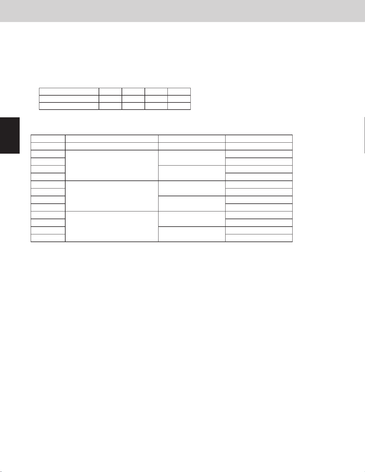
1
2
3
4
5
6
3WAY VRF SYSTEM
5. Outdoor Fan Control
5-1-3. Silent mode
This unit includes 2 types of silent modes.
See the table under the section “5-1. Fan mode” for maximum fan mode in silent mode.
Selecting the silent mode results in operation that gives priority to reducing noise, because these modes involve
restrictions on outdoor unit fan modes, the capacity will be somewhat reduced. (It may sometimes become a
maximum of -5 hp.)
* Maximum fan mode and frequency in silent mode
Type of outdoor unit 72 96 120 144
Fan mode 9 9 10 10
Frequency (Hz) 47.2 59.5 51.1 53.0
* To activate this function, it is necessary to set it to each outdoor unit.
CODE: 05
Setting No. Mode
0
1
2
3
4
5
6
7
8
9
10
11
12
* When the setting is "external input to PCB necessary", this function works by short circuiting "SILENT" pins.
* When the setting is "external input to PCB unnecessary", this function always works.
* When the setting is "silent priority", max. fan mode is decided in the following formula.
Max. fan mode = 13 - ( 35 – Ambient temperature) / 2
However, minimum fan mode is “6”, maximum is “13”. (When high static pressure mode, max is “15”)
* When the setting is "capacity priority", this function works excluding the following conditions.
Condition that silent mode interrupts
Heat exchanger [condenser] of outdoor unit: Ambient temperature ≥ 100.4°F (38°C)
Heat exchanger [evaporator] of outdoor unit: Ambient temperature ≤ 35.6°F (2°C)
This function will be useful for nighttime in summer.
* When the setting is "controlled in moderation", this function controls both "silent priority" and "capacity priority".
Thereof, “silent priority” fan mode is set within the temperature range of “capacity priority”.
Invalidity (Factory preset mode) - -
Silent priority
Capacity priority
Controlled in moderation
External input to PCB Silent mode
Necessary
Unnecessary
Necessary
Unnecessary
Necessary
Unnecessary
Silent mode
Never use
Silent mode
Never use
Silent mode
Never use
Silent mode
Never use
Silent mode
Never use
Silent mode
Never use
Control Functions
7
8
9
1 - 22
 Loading...