

Page 1
ORDER NO. ITD0804012CE
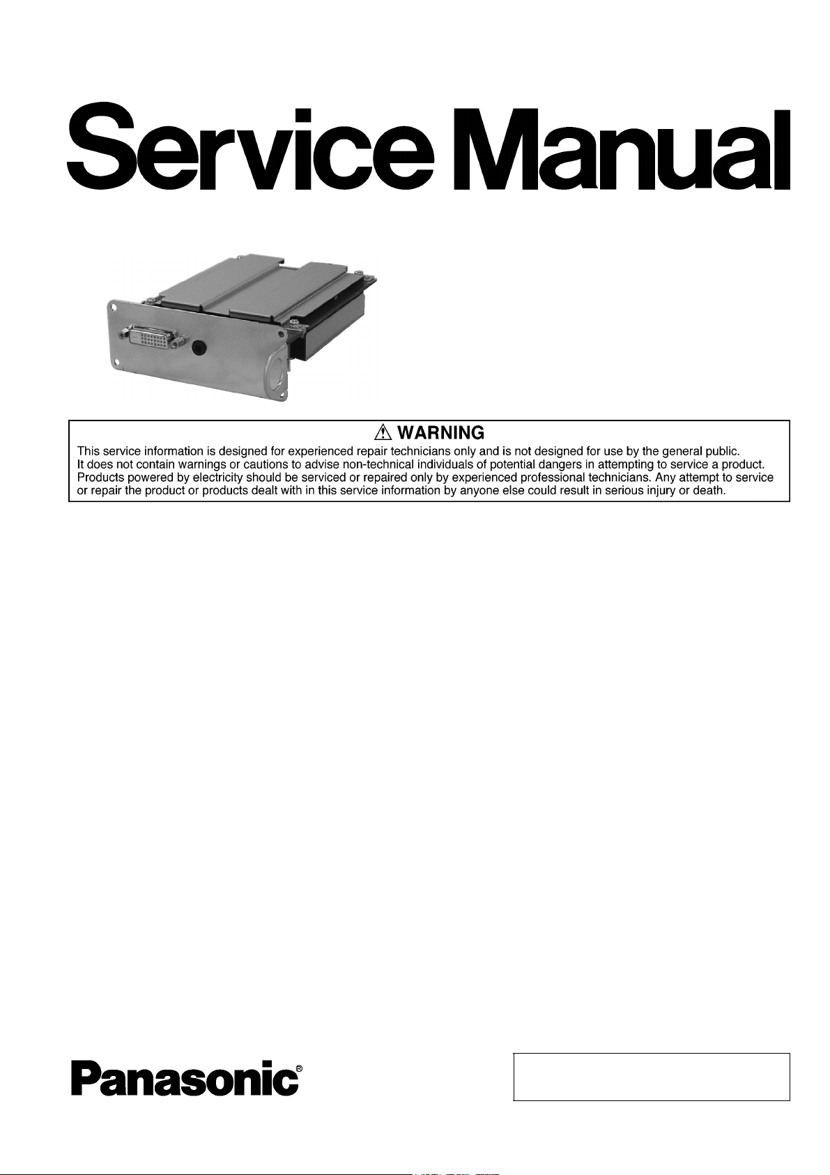
DVI-D Terminal Board
Model No. TY-FB11DD
TY-FB11DDC
B34 Canada: D10
© 2008 Matsushita Electric Industrial Co., Ltd. All
rights reserved. Unauthorized copying and distribution is a violation of law.
Page 2
1 Safety Precautions
1.1. General Guidelines
1. When conducting repairs and servicing, do not attempt to modify the equipment, its parts or its materials.
2. When wiring units (with cables, flexible cables or lead wires) are supplied as repair parts and only one wire or some of the
wires have been broken or disconnected, do not attempt to repair or re-wire the units. Replace the entire wiring unit instead.
3. When conducting repairs and servicing, do not twist the Faston connectors but plug them straight in or unplug them straight
out.
4. When servicing, observe the original lead dress. If a short circuit is found, replace all parts which have been overheated or
damaged by the short circuit.
5. After servicing, see to it that all the protective devices such as insulation barriers, insulation papers shields are properly
installed.
6. After servicing, make the following leakage current checks to prevent the customer from being exposed to shock hazards.
1.1.1. Leakage Current Cold Check
1. Unplug the AC cord and connect a jumper between the
two prongs on the plug.
2. Measure the resistance value, with an ohmmeter,
between the jumpered AC plug and each exposed metallic cabinet part on the equipment such as screwheads,
connectors, control shafts, etc. When the exposed metallic part has a return path to the chassis, the reading
should be between 1Mohm and 5.2Mohm.
When the exposed metal does not have a return path to
the chassis, the reading must be .
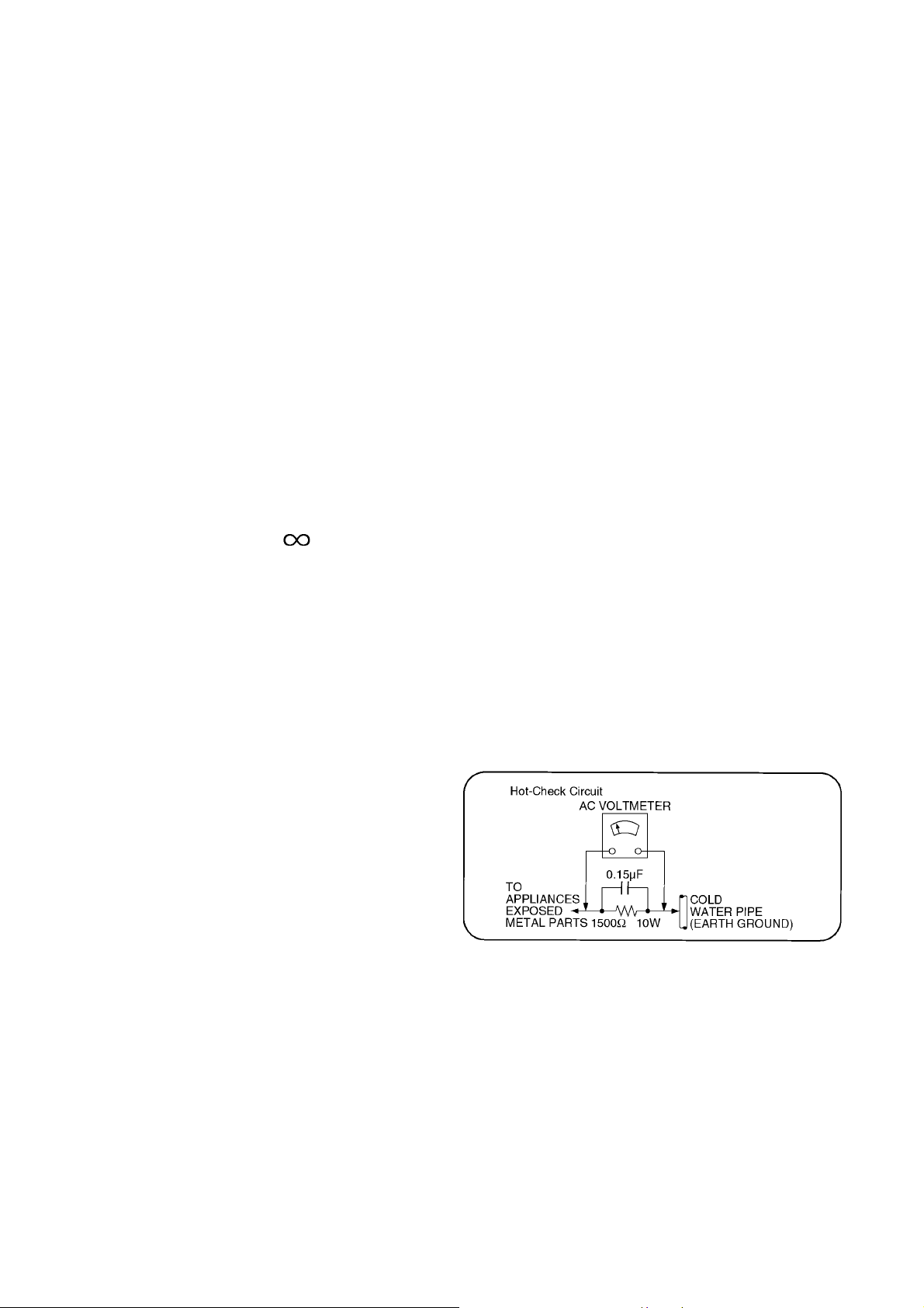
1.1.2. Leakage Current Hot Check (See Figure 1.)
1. Plug the AC cord directly into the AC outlet. Do not use
an isolation transformer for this check.
2. Connect a 1.5kohm, 10 watts resistor, in parallel with a
0.15μF capacitors, between each exposed metallic part
on the set and a good earth ground such as a water pipe,
as shown in Figure 1.
3. Use an AC voltmeter, with 1000 ohms/volt or more sensitivity, to measure the potential across the resistor.
4. Check each exposed metallic part, and measure the voltage at each point.
5. Reverse the AC plug in the AC outlet and repeat each of
the above measurements.
6. The potential at any point should not exceed 0.75 volts
RMS. A leakage current tester (Simpson Model 229 or
equivalent) may be used to make the hot checks, leakage
current must not exceed 1/2 milliamp. In case a measurement is outside of the limits specified, there is a possibility of a shock hazard, and the equipment should be
repaired and rechecked before it is returned to the customer.
Figure 1
2
Page 3
2 Warning
2.1. Prevention of Electrostatic Discharge (ESD) to Electrostatically Sensitive (ES) Devices
Some semiconductor (solid state) devices can be damaged easily by static electricity. Such components commonly are called Electrostatically Sensitive (ES) Devices. Examples of typical ES devices are integrated circuits and some field-effect transistors and
semiconductor [chip] components. The following techniques should be used to help reduce the incidence of component damage
caused by electrostatic discharge (ESD).
1. Immediately before handling any semiconductor component or semiconductor-equipped assembly, drain off any ESD on your
body by touching a known earth ground. Alternatively, obtain and wear a commercially available discharging ESD wrist strap,
which should be removed for potential shock reasons prior to applying power to the unit under test.
2. After removing an electrical assembly equipped with ES devices, place the assembly on a conductive surface such as aluminum foil, to prevent electrostatic charge buildup or exposure of the assembly.
3. Use only a grounded-tip soldering iron to solder or unsolder ES devices.
4. Use only an anti-static solder removal device. Some solder removal devices not classified as [anti-static (ESD protected)] can
generate electrical charge sufficient to damage ES devices.
5. Do not use freon-propelled chemicals. These can generate electrical charges sufficient to damage ES devices.
6. Do not remove a replacement ES device from its protective package until immediately before you are ready to install it. (Most
replacement ES devices are packaged with leads electrically shorted together by conductive foam, aluminum foil or comparable conductive material).
7. Immediately before removing the protective material from the leads of a replacement ES device, touch the protective material
to the chassis or circuit assembly into which the device will be installed.
Caution
Be sure no power is applied to the chassis or circuit, and observe all other safety precautions.
8. Minimize bodily motions when handling unpackaged replacement ES devices. (Otherwise ham less motion such as the brushing together of your clothes fabric or the lifting of your foot from a carpeted floor can generate static electricity (ESD) sufficient
to damage an ES device).
3
Page 4
2.2. About lead free solder (PbF)
Note: Lead is listed as (Pb) in the periodic table of elements.
In the information below, Pb will refer to Lead solder, and PbF will refer to Lead Free Solder.
The Lead Free Solder used in our manufacturing process and discussed below is (Sn+Ag+Cu).
That is Tin (Sn), Silver (Ag) and Copper (Cu) although other types are available.
This model uses Pb Free solder in it’s manufacture due to environmental conservation issues. For service and repair work, we’d
suggest the use of Pb free solder as well, although Pb solder may be used.
PCBs manufactured using lead free solder will have the PbF within a leaf Symbol PbF stamped on the back of PCB.
Caution
• Pb free solder has a higher melting point than standard solder. Typically the melting point is 50 ~ 70 °F (30~40 °C) higher. Please
use a high temperature soldering iron and set it to 700 ± 20 °F (370 ± 10 °C).
• Pb free solder will tend to splash when heated too high (about 1100 °F or 600 °C).
If you must use Pb solder, please completely remove all of the Pb free solder on the pins or solder area before applying Pb solder. If this is not practical, be sure to heat the Pb free solder until it melts, before applying Pb solder.
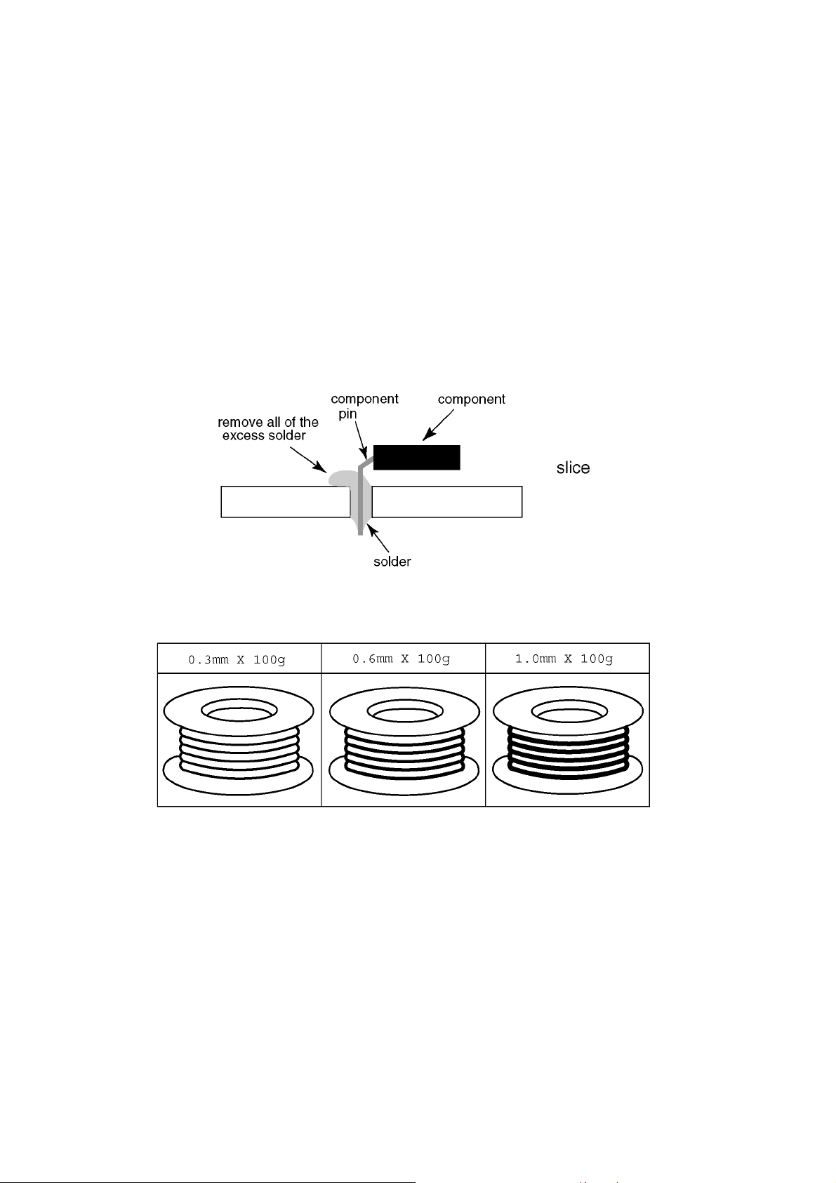
• After applying PbF solder to double layered boards, please check the component side for excess solder which may flow onto the
opposite side. (see figure below)
Suggested Pb free solder
There are several kinds of Pb free solder available for purchase. This product uses Sn+Ag+Cu (tin, silver, copper) solder. However, Sn+Cu (tin, copper), Sn+Zn+Bi (tin, zinc, bismuth) solder can also be used.
4
Page 5

3 Specifications
Term in als Video Input DVI-D 24 Pin × 1
Content Protection Compatible with HDCP 1.1
compliance with DVI Revision 1.0
Audio Input Stereo mini jack (M3) × 1
0.5 Vrms
5
Page 6
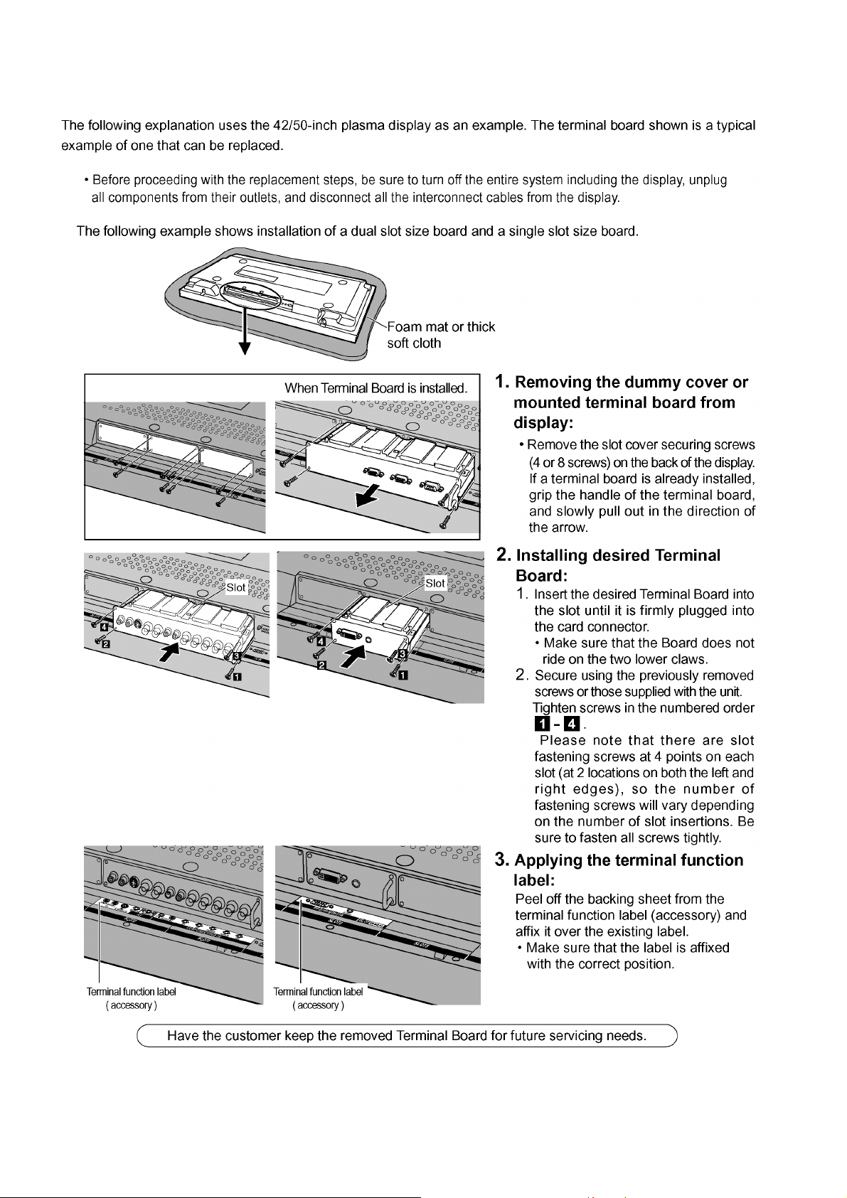
4 Installation Instructions
6
Page 7
5 Operating Instructions
7
Page 8

8
Page 9

6 Service Fixture & Tools
Note:
Extension cable kit for Slot Board is supplied as service fixtures and tools.
(Part No. TZSC07040)
9
Page 10

7 Disassembly and Assembly Instructions
7.1. Remove the HDE Board
1. Remove the screws ( ×2 ) and then remove the HDE
terminal fixed metal.
2. Remove the screws( ×4 ) and then remove the Shield
case A/B and HDE Board.
10
Page 11

8 Block Diagram
8.1. HDE-Board Block Diagram
A
JK3302
DVI AUDIO IN
R
L
FOR
FACTORY
USED
H2
Q3302
Q3303
B
D3025
FOR
FACTORY
USED
JK3301
C
DVI IN
HPS
TMDS_CDDCD
GND
TMDS_C+
DDCC
+5V
TMDS_G
N.C.
N.C.
N.C.
N.C.
N.C.
N.C.
TMDS_G
TMDS_G
TMDS_G
TMDS_D2+
TMDS_D1+
TMDS_D0+
TMDS_D2TMDS_D1TMDS_D0-
H4
8
16
24
7
15
23
6
14
22
5
13
21
4
12
20
3
11
19
2
10
18
1
9
17
DVI_CN_SDA/SCL
EDID_WP
D3011
D
DVI_CN_SDA
DVI_CN_SCL
TMDS_RX2+
TMDS_RX1+
TMDS_RX0+
TMDS_RX2TMDS_RX1TMDS_RX0-
AUDIO_R
AUDIO_L
+5V
SDA/SCL
Q3304
IC3303
LEVEL SHIFT
5V<->3.3V
VCC
B
IC3301
EEPROM
SDA
SCL WC
TMDS_RXC-
TMDS_RXC+
TMDS RX0
Q3301
DVI_5V_DET
OE2
VCC
A
Q3305
-RX2
IC3307
DVI I/F RECEIVER
VCC(+1.8V)
VCC(+3.3V)
DSCL1/DSA1
R1PWR5V
CSDA/CSCL
IC3312
RESET
VCC
VOUT
DVI_IIC
PLL
LATCH
IC3308
+1.8V
DATA RECOVERY
SYNCHRONIZATION
X3301
3
OUT4VDD
1OE2
GND
IC3310
GENX MPU
NRST RESET
SDA0
SCL0
VCC(+3.3V)
DVI_5V_DET
HPD
AND
XTAL IN
N_FHD
SDA2
SCL2
SDA1
SCL1
OSCXO
OSCXI
TMDS
DECODER
IC3314
CONFIG ROM
DATA
ASD
VCC
DCLK
EPCS_DATA
EPCS_ASD
EPCD_DCLK
RGB
OUTPUT
RESET
GENX_COMTROL_IIC
X3302
10MHz
R0-R7
G0-G7
B0-B7
HSYNC,VSYNC,DOCK
TVLOAD_IIC
IC3341
R0-R7
G0-G7
B0-B7
H,V,CK
CLK7(27MHz)
NRST
FPGA
VCC(+3.3V)
VCC(+1.2V)
SDA/SCL
IC3320
LEVEL SHIFT
5V<->3.3V
A
O_CLK
CLK4
VCC
S2
S1
B
EVEN_R0-R7
EVEN_G0-G7
EVEN_B0-B7
H,V,CLK
ODD_R0-R7
ODD_G0-G7
ODD_B0-B7
SLOT_IIC
XIN
CKOUT
FREQ0
FREQ1
IC3342
+1.2V
IC3343
CPG
VCC(+3.3V)
SLOT_IIC
+3.3V
VCC(+3.3V)
R0-R7
G0-G7
B0-B7
H,V,CK
R0-R7
G0-G7
B0-B7
IC3346
LVDS TX
SDA/
SCL
TA1 -TE1
TA2
IC3319
EEPROM
IC3345
+3.3V
VCC
WR
-TE2
TCK1
PA3301
TO
SLOT1,SLOT2
H1
A26
AUDIO_OUT_L
A28
AUDIO_OUT_R
A19
+5V
B19
+5V
B39
PLUG DET
A21
+9V
B21
+9V
B38
+15V
B37
+15V
A22
STB+5V
LVDS_TX4+
A3
LVDS_TX4-
A2
B3
LVDS_TX0+
LVDS_TX0-
B2
A10
LVDS_TX7+
A9
LVDS_TX7-
A5 LVDS_TX5+
LVDS_TX5-A4
LVDS_TX1+
B6
LVDS_TX1-
B5
B12
LVDS_TXC+
B11
LVDS_TXC-
LVDS_TX6+
A8
A7 LVDS_TX6-
A13
LVDS_TX8+
A12
LVDS_TX8-
B9
LVDS_TX2+
B8
LVDS_TX2-
A15
LVDS_TX9+
A14
LVDS_TX9-
B15
LVDS_TX3+
B14
LVDS_TX3-
A23
HD/FHD DET
B25
IIC_SCL
B24
IIC_SDA
B23
SRQ
FOR
FACTORY
USED
H3
TA1+
TA1-
TB1+
TB1-
TC1+
TC1-
TD1+
TD1-
TE1+
TE1-
AUDIO_L
AUDIO_R
+15V
TCK1+
TCK1-
TA2+
TA2-
TB2+
TB2-
TC2+
TC2-
TD2+
TD2-
TE2+
TE2-
+9V
STB+5V
+5V
E
TY-FB11DD/C
HDE-Board Block Diagram
TY-FB11DD/C
HDE-Board Block Diagram
1
25
3
4
876
11
Page 12

9 Schematic Diagram
9.1. Schematic Diagram Note
12
Page 13

9.2. HDE-Board (1/3) Schematic Diagram
L3357
J0JHC0000075
C3416
C3421
6.3V
16V
0.1u
10u
7
C3372
10V
1u
6
VSYNC
HSYNC
DE
L3325
C3420
6.3V
10u
R3578
R3577
3.3k
FPGA_RST
J0JHC0000075
C3423
16V
0.1u
DVI_RST
C3389
C3388
R3452
50V
18p
10MHz
85
86
P2487P2588P2689P27
IVDD
IC3310
MNZSFD7GDE1
GENX MPU
H0J100500030
R3453
820
82
83
VSS
OSCXO84OSCXI
TVRP845
50V
15p
X3302
C3390
16V
C3393
0.1u
16V
C3392
0.1u
10V
1u
C3394
10V
1u
74
75
79
80
VDD
N.C.76N.C.77N.C.78IVDD
N.C.81RONA
VPPEX
P66/SBI2
P65/SBO2
P76/CEC0
R3459
100
R3511
47k
10k
R3464
66
67
68
65
63
P3069P3170P3271P3372P3473P35
62
61
N.C.
60
N.C.
59
P17
58
P16
57
N.C.
P15
56
P14
P72/SDA164P73/SCL1
55
P13
54
P12
53
P11
52
P10
51
VSS
50
IVDD
49
P23
48
P22
47
P21
46
P20
45
P50/RMIN/IRQ0
44
N.C.
43
N.C.
42
N.C.
41
N.C.
40
P71/SCL0
39
P70/SDA0
P60/SBO0A34P61/SBT0A35P62/SBI0A
38
P07/IRQ8
VDD
IVDD
P46
R3502 0
10k
R3454
47k
R3503
GENX_NBOOT
P06/IRQ7
P05/IRQ6
R3540
47k
GenX-EEP_WP
37
36
33
31
32
30
C3395
10V
1u
R3509 47k
R3507 47k
C3396
16V
0.1u
22
R350022R3499
R3494
R3493 10k
22
R3465
22
R3481
10k
R3505
47k
R3504
10k
C3397
16V
R3479
47k
10k
R3466
22
R3495
R3467
22
TVLOAD_SCL
TVLOAD_SDA
HPD
R3501
100
DVI_5V_DET
0.1u
DVI_INT
10k
R3461
DVI_SCL
DVI_SDA
R3451
R3450
C3385
C3384
10V
16V
0.1u
10u
0
4.7k
R3544
4.7k
R3545
R3441
R3449
C3386
16V
0.1u
R3506
R3508
GENX_NBOOT
100
47k
47k
47k
GENX_NBOOT
1k
33
100
97
100
101
102
103
104
105
106
107
108
109
110
111
112
113
114
115
116
117
118
119
120
121
122
123
124
125
126
127
128
47k
R3448
C3387
10V
1u
90
92
93
94
95
96
NRST
NBOOT
P64/SBI191P63/SBO1
TRCST
NTEST
TRCD0
SCLOCK
SDATA
TRCD1
TRCD2
TRCD3
EXTRG098EXTRG199TRCCLK
P90
P91
VSS
IVDD
P92
P93
P80/ADIN0
P81/ADIN1
P82/ADIN2
P83/ADIN3
P84/ADIN4
P85/ADIN5
P86/ADIN6
P87/ADIN7
P74/SDA2/CECAVL1B
P75/SCL2/CECAVL1A
P36
P37
PC0
PC1
P40/TMIO0/SYSCLK
P47
P41/TMIO1
P42/TMIO2
PB0
P43/TMIO3
PB1
P44/TMIO45P00/TMIO56P017P028P03/SBT0B9P04/SBO0B10P51/IRQ211P52/IRQ312PB213PB314PB415PB516PB617PB718P53/IRQ419P54/IRQ520PA721PA622PA523VSS24PA425PA326PA227PA1/IRQ128PA029P45
1
2
3
4
47k
R3573
R3571 47k
R3572 47k
FPGA_CLK
B0
B1
B2
B3
B4
B5
B6
B7
G0
G1
G2
G3
G4
G5
G6
G7
DOCK
R0
R1
R2
R3
R4
R5
R6
R7
GENX_CTRL_SDA
GENX_CTRL_SCL
C3417
6.3V
10u
L3328
C3357
C3358
C3359
C3360
C3361
C3362
C3356
10V
1u
J0JHC0000034
0.1u
0.1u
0.1u
0.1u
0.1u
0.1u
C3363
6.3V
2.2u
C3364
50V
470p
J0JHC0000034
J0JHC0000034
R3404
C3414
6.3V
10u
IC3308
C0DBFFD00003
MAIN 1.8V
1
Vin
Vo
2
NC
sub
3
GND
45
CONT
Cn
L3312
L3314
R3496 22
R3492 22
R3491 82
EXB2HV820JV
EXB2HV820JV
EXB2HV820JV
10
R3410
R3406
R3407
/PLUG_DET
5V
C3313
1u
1
/OE1
2
A1
3
B2
45
GND
IC3303
C0JBAZ002269
5V<=>3.3V
FOR
FACTORY
USE
1
2
3
4
10V
R3350
10k
8
Vcc
TP3317
7
/OE2
6
B1
R3357
33
A2
R3356
33
3.3VTMDS
L3368
TMDS_RXC-
TMDS_RXC+
TMDS_RX0-
TMDS_RX0+
L3310
J0JHC0000034
TMDS_RX1-
TMDS_RX1+
J0JHC0000034
C3497
6.3V
10u
TMDS_RX2-
TMDS_RX2+
C3328
16V
0.1u
C3329
10V
1u
C3320
1u
10V
C3321
1u
10V
C3322
1u
10V
C3323
1u
10V
C3318
10V1u
C3319
C3324
0.1u
16V
1u
10V
C3325
1u
10V
C3326
1u
10V
C3327
1u
10V
A
DVI_CN_SCL
DVI_CN_SDA
R3349
TP3347
10k
R3346
33
R3345
33
TVRP844
IC3301
C3EBDC000067
EDID EEPROM
1
E0
B
C
2
E1
3
E2
4
VSS
JK3301
K1FB124B0025
DVI I N
-
HPS
TMDS_C-
DDCD
GND
TMDS_C+
DDCC
+5V
TMDS_G
N.C.
N.C.
N.C.
N.C.
N.C.
N.C.
TMDS_G
TMDS_G
TMDS_G
TMDS_D2+
TMDS_D1+
TMDS_D0+
TMDS_D2-
TMDS_D1-
TMDS_D0-
VCC
WC
SCL
SDA
8
16
24
7
15
23
6
14
22
5
13
21
4
12
20
3
11
19
2
10
18
1
9
17
D3309
MAZ30560ML
R3022
10k
R3023
R3024
4.7k
D3001
EZAEG2A50AX
C3488
16V
0.1u
C3426
16V
0.1u
D3004
EZAEG2A50AX
4.7k
R3025
56
R3026
56
D3002
EZAEG2A50AX
L3364
J0JHC0000034
D3003
EZAEG2A50AX
D3011
B0HCMM000014
D3307
MAZ30560ML
8
7
6
5
D3025
B0HCMM000014
D3310
MAZ30560ML
5V
H4
DVI_CN_SCL
DVI_CN_SCL
DVI_CN_SDA
DVI_CN_SDA
TMDS_RXC-
DVI_CN_SDA
TMDS_RXC+
DVI_CN_SCL
D3311
MAZ30560ML
TMDS_RX2+
TMDS_RX1+
TMDS_RX0+
TMDS_RX2-
TMDS_RX1-
TMDS_RX0-
D
D3005
EZAEG2A50AX
D3009
EZAEG2A50AX
D3006
EZAEG2A50AX
D3010
EZAEG2A50AX
D3008
EZAEG2A50AX
EZAEG2A50AX
HPD
DVI_5V_DET
R3431
10k
5V
R3518
1k
D3308
Q3304
R3463
R3462
39
2SD0601ASL
10k
C3494
16V
0.1u
R3469
10k
C3495
16V
0.1u
Q3301
2SD0601ASL
D3007
EZAEG2A50AX
E
22
R3470
DVI_SCL
Q3305
2SK122800L
R3510
4.7k
R3512
4.7k
R3377
10k
C3335
0.01u
25V
R3374
10k
C3333
25V
0.01u
C3330
16V
0.1u
C3498
16V
0.1u
35
36
37
38
39
R0XC+
40
AGND
41
AVCC
42
R0X0-
43
R0X0+
44
AGND
45
AVCC
46
R0X1-
47
R0X1+
48
AGND
49
AVCC
50
R0X2-
51
R0X2+
52
AGND
53
TMDSPGND
54
PVCC1
55
RSVD_A
56
AVCC
57
R1XC-
58
R1XC+
59
AGND
60
AVCC
61
R1X0-
62
R1X0+
63
AGND
64
AVCC
65
R1X1-
66
R1X1+
67
AGND
68
AVCC
69
70
74
73
0.1u
C3331
16V
DVI_SDA
SGD
C3340
16V
0.1u
C3336
16V
4.7k
4.7k
R3364
R3365
33
34
R1PWR5V
AVCC
R0XC-
R1X2-71R1X2+72AGND
IOVCC77MUTEOUT78SPDIF79CVCC1880CGND81NC82NC83NC84SD085WS86SCK87NC88MCLKOUT89IOVCC90IOGND91CGND92CVCC1893NC94AUDPVCC1895AUDPGND96XTALOUT97XTALIN98XTALVCC99REGVCC
75
76
0.1u
C3332
16V
0.1u
22
22
C3341
16V
0.1u
R3380
R3381
0.1u
C3337
16V
22
24
25
27
29
CGND
CSDA28CSCL
IOGND26IOVCC
DSDA130DSCL131DSDA032DSCL0
R0PWR5V
CVCC18
CGND
PVCC0
CGND
CVCC18
IOGND
0.1u
C3334
16V
CVCC1823CVCC18
IC3307
C1AB00002848
DVI I/F RECEIVER
C3338
CGND
C3339
J0JHC0000075
MAIN1.8V
C3354
C3346
C3344
16V
0.1u
10u
6.3V
0.1u
16V
L3311
C3353
16V
16V
0.1u
0.1u
10NC11NC12NC13NC14NC15
17NC18NC19NC20NC21
IOGND16IOVCC
EVNODD
VSYNC
HSYNC
Pad
Thermal
IOGND
CLK48B
CGND
RSVDL
100NC101
0.1u
0.1u
0.1u
C3351
C3345
C3342
16V
R3394
16V
16V
C3349
16V
0.1u
DVI_CLK
27MHz
10
R3401
R3408
10
2
GND3OUT
X3301
H1A2705B0032
VDD
OE
1
4
C3476
16V
0.1u
C3355
16V
6.3V
0.1u
10u
1DE2
3
4
6NC7NC8NC9
144
143
IOGND5IOVCC
142
Q3
141
16V
Q4
140
CVCC18
139
CGND
Q2
Q1
Q0
138
Q5
137
Q6
136
16V
IOGND
135
IOVCC
134
Q7
133
Q8
132
Q9
131
Q10
130
16V
Q11
129
CVCC18
128
CGND
127
Q12
126
Q13
125
Q14
124
16V
Q15
123
IOVCC
122
ODCK
121
IOGND
120
Q16
119
Q17
118
Q18
117
Q19
116
16V
CGND
IOVCC
Q23
Q22
115
CVCC18
114
Q20
113
Q21
112
111
110
RESET
SCDT
INT
CVCC18
109
102
103
104
22
R3399
1.8k
DVI_RST
DVI_INT
16V
105
106
107
108
4.7k
R3398
1
2
3
4
N_FHD
F
TY-FB11DD/C
HDE-Board (1/3) Schematic Diagram
!
HDE-BOARD TXNHDE10UNT (1/3)
13
FPGA_PWD
GENX_NBOOT
LVDS_PWD
TY-FB11DD/C
5
6
HDE-Board (1/3) Schematic Diagram
74312
956 8
Page 14

9.3. HDE-Board (2/3) Schematic Diagram
1
2
C3422
6.3V
10u
FOR
FACTO RY
USE
DCLK
GND
CONF_DONE
VCC(TRGT)
nCONFIG
nCE
DATAOUT
nCS
ASDI
GND
J0JHC0000075
C3425
16V
0.1u
R3488
10k
L3327
R3517 47
1
XIN
XIN
XOUT
2
XOUT
VSS
3
VSS
SEL
4
SEL
IC3343
C0ZBZ0001561
IC3341
C1ZBZ0003575
ALTERA CYCLONE2 (BGA)
FPGA_CLK
CPG
FREQ1
FREQ0
CKOUT
!
HDE-BOARD TXNHDE10UNT (2/3)
3
IC3342
C0DBEHG00006
PLL 1.8V
FREQ1
8
FREQ0
7
VDD
6
VDD
R3651
10
CKOUT
5
GND
IC3341 D3 IO
IC3341 D7 IO
IC3341 D8 IO
IC3341 D9 IO
IC3341 D10 IO
IC3341 E3 IO
IC3341 E4 IO
IC3341 E5 IO
IC3341 E6 IO
IC3341 E13 IO
IC3341 F5 IO
IC3341 F6 IO
IC3341 F7 IO
IC3341 F8 IO
IC3341 F9 IO
IC3341 F10 IO
IC3341 G4 IO
IC3341 G6 IO
IC3341 G7 IO
IC3341 G10 IO
IC3341 G11 IO
IC3341 G12 IO
IC3341 G13 IO
IC3341 H6 IO
IC3341 H11 IO
IC3341 H12 IO
IC3341 H13 IO
IC3341 J4 IO
IC3341 J6 IO
IC3341 J11 IO
IC3341 J12 IO
10k
R3641
R3400
IC3341 K4 IO
IC3341 K5 IO
IC3341 K6 IO
IC3341 K7 IO
IC3341 K10 IO
IC3341 K13 IO
IC3341 L4 IO
IC3341 L7 IO
IC3341 L8 IO
IC3341 L9 IO
IC3341 L10 IO
IC3341 L11 IO
IC3341 L12 IO
IC3341 L14 IO
IC3341 M3 IO
IC3341 M4 IO
IC3341 M11 IO
IC3341 M12 IO
IC3341 M14 IO
IC3341 N16 IO
IC3341 N3 IO
IC3341 N4 IO
IC3341 N6 IO
IC3341 N7 IO
IC3341 N8 IO
IC3341 N9 IO
IC3341 N10 IO
IC3341 N11 IO
IC3341 N12 IO
C3400
50V
1000p
10k
3.3VAnalog
C3399
0.1u
10k
R3644
CLK Pin
TEST_Pin
16V
SEL
R3482
R3484
R3485
R3486
R3515
R3519
L3322
J0JHC0000075
C3455
6.3V
10u
IC3341 K15 IO
IC3341 K16 IO
IC3341 L15 IO
IC3341 L16 IO
IC3341 H2 CLK0
IC3341 H1 CLK1
IC3341 J2 CLK2
IC3341 J1 CLK3
IC3341 H16 CLK4
IC3341 H15 CLK5
IC3341 J15 CLK6
IC3341 J16 CLK7
10k
IC3341 F3 IO
10k
IC3341 F13 IO
10k
IC3341 E14 IO
10k
IC3341 M1 IO
10k
IC3341 M15 IO
10k
IC3341 M16 IO
IC3341 N14 IO
IC3341 N15 IO
IC3341 P2 IO
IC3341 P3 IO
IC3341 P4 IO
IC3341 P5 IO
IC3341 P6 IO
IC3341 P11 IO
IC3341 P12 IO
IC3341 P13 IO
IC3341 P14 IO
IC3341 P15 IO
IC3341 P16 IO
C3460
16V
0.1u
S0
O_CLK
S2
S1
TP3360
L3329
J0JHC0000075
+
C3407
C3408
C3406
16V
0.1u
C3403
16V
4V
6.3V
0.01u
100u
10u
POWER BLOCK(1.2V/3.3V/GND)
L3370
J0JHC0000075
C3480
6.3V
10u
J0JHC0000075
C3526
C3527
50V
50V
1000p
1000p
C3520
C3521
16V
16V
0.1u
0.1u
L3358
C3410
C3411
6.3V
10u
C3542
16V
0.1u
(FIN)
GND(FIN)
OUT5ADJ
4
R3439
33k
R3438
20k
C3415
C3405
16V
10V
0.1u
1u
CTL2Vcc
1
R3433
10k
L3326
J0JHC0000075
C3418
C3404
C3424
6.3V
10V
16V
10u
1u
0.1u
LVDS_OUT
1.2V
C3522
50V
50V
1000p
1000p
C3449
C3450
16V
16V
0.1u
0.1u
3.3VFPGA
C3412
C3541
6.3V
16V
0.1u
10u
C3546
C3547
16V
0.1u
C3538
C3537
16V
0.1u
C3531
C3532
16V
0.1u
C3446
50V
50V
50V
50V
1000p
1000p
1000p
C3445
C3443
C3444
16V
16V
16V
0.1u
0.1u
0.1u
L3343
J0JHC0000075
C3442
6.3V
10u
L3344
J0JHC0000075
C3440
6.3V
10u
C3540
C3539
16V
16V
16V
0.1u
0.1u
0.1u
C3545
C3544
16V
16V
16V
0.1u
0.1u
0.1u
C3534
C3536
16V
16V
16V
0.1u
0.1u
0.1u
C3529
C3530
16V
16V
16V
0.1u
0.1u
0.1u
IC3341 J7 VCCINT
1000p
IC3341 H10 VCCINT
IC3341 H7 VCCINT
IC3341 G9 VCCINT
IC3341 F11 VCCD_PLL2
IC3341 L6 VCCD_PLL1
C3427
16V
0.1u
IC3341 N5 GND_PLL1
IC3341 L5 GND_PLL1
IC3341 F12 GND_PLL2
IC3341 D12 GND_PLL2
1.2V(PLL)
IC3341
M5 VCCA_PLL1
C3434
C3441
50V
16V
1000p
0.1u
IC3341 M6 GNDA_PLL1
1.2V(PLL)
IC3341 E12 VCCA_PLL2
C3439
C3431
50V
16V
0.1u
1000p
IC3341 E11 GNDA_PLL2
3.3V(I/O)
IC3341 R1 VCCIO1
IC3341 G3 VCCIO1
C3535
16V
IC3341 K3 VCCIO1
0.1u
IC3341 B1 VCCIO1
IC3341 A2 VCCIO2
IC3341 A15 VCCIO2
IC3341 C10 VCCIO2
C3543
16V
IC3341 C7 VCCIO2
0.1u
IC3341 E10 VCCIO2
IC3341 E7 VCCIO2
IC3341 K14 VCCIO3
IC3341 R16 VCCIO3
IC3341 G14 VCCIO3
C3533
16V
IC3341 B16 VCCIO3
0.1u
IC3341 M10 VCCIO4
IC3341 M7 VCCIO4
IC3341
P7 VCCIO4
IC3341 P10 VCCIO4
C3528
16V
IC3341 T2 VCCIO4
0.1u
IC3341 T15 VCCIO4
GND
IC3341
A1 GND
IC3341 B2 GND
IC3341 A16 GNDIC3341
IC3341 E8 GND
IC3341 E9 GND
IC3341 B15 GND
IC3341 C8 GND
IC3341 C9 GND
IC3341 G8 GND
IC3341 H3 GND
IC3341 H8 GND
IC3341 H9 GND
IC3341 H14 GND
IC3341 J3 GND
IC3341 J8 GND
IC3341 J9 GND
IC3341 J14 GND
IC3341 K9 GND
IC3341 M8 GND
IC3341 M9 GND
IC3341 P8 GND
IC3341 P9 GND
IC3341 R2 GND
IC3341 T1 GND
IC3341 R15 GND
IC3341 T16 GND
IC3341 K8 VCCINT
IC3341 J10 VCCINT
C3432
C3447
C3448
C3523
GENX_CTRL_SDA
GENX_CTRL_SCL
S/D_SEL
N_FHD
IC3341E2IO
IC3341E1IO
IC3341D2IO
EXB2HV820JV
IC3341D1IO
IC3341C2IO
IC3341C1IO
IC3341C4IO
IC3341D4IO
IC3341C5IO
IC3341D5IO
IC3341C6IO
EXB2HV820JV
IC3341D6IO
IC3341A3IO
IC3341A4IO
IC3341B4IO
IC3341A5IO
IC3341B5IO
IC3341A6IO
IC3341B6IO
EXB2HV820JV
IC3341A7IO
IC3341B7IO
IC3341A8IO
IC3341B8IO
IC3341A9IO
IC3341B9IO
IC3341A10IO
IC3341B10IO
EXB2HV820JV
IC3341A11IO
IC3341B11IO
IC3341A12IO
IC3341B12IO
IC3341A13IO
IC3341B13IO
IC3341A14IO
IC3341B14IO
EXB2HV820JV
IC3341D11IO
IC3341C11IO
IC3341C12IOIC3341 K11 IO
IC3341D13IO
IC3341C13IO
IC3341D14IO
IC3341C14IO
R3418
IC3341C16IO
R3422
IC3341C15IO
EXB2HV820JV
IC3341D16IO
IC3341D15IO
IC3341E16IO
IC3341E15IO
IC3341F16IO
IC3341F15IO
IC3341G16IO
IC3341G15IO
R3427
R3428
R3429
R3423
R3424
R3425
R3411
R3417
R3426
R3476 0
R3477 0
R3483
82
82
56
82
82
33
LVDS_BE3
LVDS_GO2
LVDS_CLKIN1
LVDS_DE1
LVDS_VSYNC1
LVDS_HSYNC1
LVDS_BE7
LVDS_BE6
LVDS_BE5
LVDS_BE4
LVDS_BO1
LVDS_BE1
LVDS_BE0
LVDS_BO0
LVDS_GO1
LVDS_GO0
LVDS_RO1
LVDS_RO0
LVDS_BO3
LVDS_GE1
LVDS_GE0
LVDS_BO2
LVDS_GO7
LVDS_GO6
LVDS_GO5
LVDS_GO4
LVDS_GO3
LVDS_RE1
LVDS_RE0
LVDS_BO7
LVDS_BO6
LVDS_BO5
LVDS_BO4
LVDS_GE2
LVDS_RE7
LVDS_RO7
LVDS_RO6
LVDS_BE2
LVDS_GE7
LVDS_RE6
LVDS_RE5
LVDS_RE4
LVDS_RE3
LVDS_RE2
LVDS_RO5
LVDS_RO4
LVDS_GE6
LVDS_GE5
LVDS_RO3
LVDS_RO2
LVDS_GE4
LVDS_GE3
IC3341 L2 IO
IC3341 K1 IO
IC3341 F14 IO
IC3341 L3 IO
3.3VCONFIG
IC3314
C1ZBZ0003631
CONFIG ROM
1
nCS
2
DATA
3
VCC
4
GND
TVRP843
R3650
47
R3478
47
C3402
10V
1u
IC3312
C0EBE0000066
RESET
C3398
16V
0.1u
5
Vcc4Vout
SUB
1NC2
GND
3
R3473
470
open collector
RESET 2.8V
3
EPCS_DATA
EPCS_NCS
8
VCC
7
VCC
R3649
47
6
DCLK
EPCS_ASD
5
ASDI
R3489
C3413
10k
16V
0.1u
EPCS_DCLK
C3419
6.3V
10u
R3490
10k
H2
1
2
3
4
5
6
7
8
9
10
4
3.3VFPGA
R3475
10k
nCSO
ASDO
FPGA_PWD
FPGA_RST
IC3341N13IO
IC3341B3IO
IC3341M13nSTATUS
IC3341J5nCONFIG
IC3341F4IO
IC3341H4DCLK
IC3341F1DATA0
IC3341C3IO
IC3341G5nCE
IC3341L13CONF_DONE
IC3341H5TDI
IC3341F2TCK
IC3341G1TMS
IC3341G2TDO
IC3341K12MSEL1
IC3341J13MSEL0
TMDS_RX => FPGA
IC3341 M2 IO
IC3341 N1 IO
IC3341 N2 IO
IC3341 P1 IO
IC3341 T3 IO
IC3341 R3 IO
IC3341 T4 IO
IC3341 R4 IO
IC3341 T5 IO
IC3341 R5 IO
IC3341 T6 IO
IC3341 R6 IO
IC3341 T7 IO
IC3341 R7 IO
IC3341 T8 IO
IC3341 R8 IO
IC3341 T9 IO
IC3341 R9 IO
IC3341 T10 IO
IC3341 R10 IO
IC3341 T11 IO
IC3341 R11 IO
IC3341 T12 IO
IC3341 R12 IO
IC3341 T13 IO
IC3341 R13 IO
IC3341 T14 IO
IC3341 R14 IO
GENX
GENX
R3474
10k
R3487
10k
R3521 1k
R3647 1k
R3646 1k
1k
R3471
1k
R3472
DP_CLK
IC3341 L1 IO
K2 IO
NCONFIG
EPCS_DCLK
EPCS_DATA
EPCS_ASD
FPGA_PWD
FPGA_RST
INIT_DONE
DEV_CLR
VSYNC
HSYNC
DE
B0
B1
B2
B3
B4
B5
B6
B7
G0
G1
G2
G3
G4
G5
G6
G7
DOCK
R0
R1
R2
R3
R4
R5
R6
R7
5
11
12
13
6
TY-FB11DD/C
HDE-Board (2/3) Schematic Diagram
12 1410 11 16 181513 17
14
TY-FB11DD/C
HDE-Board (2/3) Schematic Diagram
14
Page 15

9.4. HDE-Board (3/3) Schematic Diagram
11
12
!
HDE-BOARD TXNHDE10UNT (3/3)
13
L3361
J0JHC0000034
LVDS_BO5
LVDS_BO6
LVDS_BO7
LVDS_RE0
LVDS_RE1
LVDS_GO3
LVDS_GO4
LVDS_GO5
LVDS_GO6
LVDS_GO7
LVDS_BO2
C3465
16V
0.1u
LVDS_GE0
LVDS_GE1
LVDS_BO3
LVDS_RO0
LVDS_RO1
LVDS_GO0
LVDS_GO1
LVDS_BO0
C3466
16V
0.1u
LVDS_BE0
LVDS_BE1
LVDS_BO1
14
TY-FB11DD/C
HDE-Board (3/3) Schematic Diagram
DCDC 15.7V => 3.3V
TP3362
R3421
0
AUDIO
JK3302
K2HC103B0105
DVI AUDIO IN
LVDS_BO4
LVDS_GE2
LVDS_RE7
C3493
6.3V
10u
107
108
106
109
110
111
112
B19/TE11
113
VCC
114
GND
115
R20/TE12
116
R21/TE13
117
R22/TE14
118
R23/TE15
119
R24/TE16
120
R25/TA20
121
R26/TA21
122
R27/TA22
123
R28/TA23
124
R29/TA24
125
VCC
126
GND
127
G20/TA25
128
G21/TA26
129
G22/TB20
130
G23/TB21
131
G24/TB22
132
G25/TB23
133
G26/TB24
134
G27/TB25
135
G28/TB26
136
G29/TC20
137
VCC
138
GND
139
B20/TC21
140
B21/TC22
141
B22/TC23
142
143
144
1
2
3
LVDS_BE4
LVDS_BE5
C3451
LVDS_GE5
L3360
G1C330MA0363
+
C3401
4V
10V
68u
10u
D3301
B0JCPE000004D3303
C3489
16V
1u
R3436
R3446
R3440
33k
100
100
C3490
16V
1u
LVDS_RO3
C3463
16V
0.1u
82
84
VCC83GND
R16/TA1685R17/TB1086R18/TB1187R19/TB1288G10/TB1389G11/TB1490G12/TB1591G13/TB1692G14/TC10
PGND
PVCC
PGND
PGND
PVCC
PGND
R3430
R3458
10k
LVDS_PWD
S/D_SEL
D3302
LVDS_RE4
LVDS_RE3
16V
B0BC6R600005
R3435
180k
R3445
180k
LVDS_RE2
LVDS_RO5
C3459
16V
0.1u
93
95
VCC94GND
G15/TC1196G16/TC1297G17/TC1398G18/TC1499G19/TC15
IC3346
C0ZBZ0001568
LVDS TX
LVDS_CLKIN1
LVDS_GO2
LVDS_BE3
L3366
EXC3BB221H
L3367
EXC3BB221H
LVDS_RO4
LVDS_GE6
R3413
0
R3412
26.1k
R3415
B0BC4R700007
10k
R
L
LVDS_RO7
LVDS_RO6
LVDS_RE6
LVDS_RE5
LVDS_BE2
LVDS_GE7
C3464
16V
0.1u
100
101
102
103
104
105
VCC
GND
B10/TC16
B11/TD10
B12/TD11
B13/TD12
B14/TD13
B15/TD14
B16/TD15
N/C
B17/TD16
B18/TE10
B23/TC24
B24/TC25
B25/TC26
B26/TD20
B27/TD21
VCC
GND5B28/TD226B29/TD237HSYNC1/TD248VSYNC1/TD259DE1/TD2610HSYNC2/TE2011VSYNC2/TE2112DE2/TE2213VCC14GND15CLKIN116CLKIN217CONT11/TE2318CONT12/TE2419CONT21/TE2520CONT22/TE2621R/F22RS23MODE324MAP25MODE126MODE027MODE228ASYNC29N/C30/PDWN31PRBS32Reserved33N/C
4
C3467
0.1u
LVDS_DE1
LVDS_VSYNC1
LVDS_HSYNC1
LVDS_BE6
LVDS_BE7
LVDS_RO2
10k
C3438
25V
0.01u
R3447
LVDS_GE4
LGND38TE2+39TE2-
R3437
R3442
R3455
15k
100
15k
R3456
33k
LVDS_GE3
76
R10/TA1077R11/TA1178R12/TA1279R13/TA1380R14/TA1481R15/TA15
TA1+71TA1-72LGND
R3420
4.7
R3443
100
R3457
74
75
TB1-
TB1+
LVCC
LGND
TC1-
TC1+
TCLK1-
TCLK1+
LVCC
LGND
TD1-
TD1+
TE1-
TE1+
LVCC
LGND
TA2-
TA2+
TB2-
TB2+
LVCC
LGND
TC2-
TC2+
TCLK2-
TCLK2+
LVCC
LGND
TD2-
TD2+
34
35
IC3345
C0DBAYY00183
AVR 3.3V
1
BS
2
VIN
3
SW
4
GND
Q3302
2SD0601ASL
R3444
100
1k
Q3303
2SD0601ASL
R3460
100
1k
TP3363
L3363
J0JHC0000034
C3478
6.3V
10u
C3430
16V
0.1u
C3429
50V
1000p
73
70
69
68
67
66
65
64
63
62
61
60
59
58
57
56
55
54
53
52
51
50
49
48
47
46
45
44
43
42
41
40
37
36
C3468
C3428
50V
1000p
J0JHC0000034
16V
0.1u
TP3361
PA3301
K5H4022A0023
C3409
C3454
R3402
25V
25V
100k
10u
0.1u
8
SS
C3436
25V
0.1u
7
EN
6
COMP
5
FB
L3369
J0JHC0000034
+
C3491
C3492
50V
16V
0.01u
47u
L3362
C3483
6.3V
10u
LVDS_TA1-
LVDS_TA1+
LVDS_TB1-
LVDS_TB1+
C3456
50V
1000p
C3457
16V
0.1u
C3461
50V
1000p
C3462
16V
0.1u
C3469
50V
1000p
C3470
16V
0.1u
C3471
50V
1000p
C3472
16V
0.1u
C3477
50V
1000p
C3487
16V
0.1u
AUDIO_R
AUDIO_L
LVDS_TC1-
LVDS_TC1+
LVDS_TCLK1-
LVDS_TCLK1+
9V
LVDS_TD1-
LVDS_TD1+
LVDS_TE1-
LVDS_TE1+
LVDS_TA1-
LVDS_TA1+
LVDS_TB1-
LVDS_TB1+
LVDS_TA2-
LVDS_TA2+
LVDS_TB2-
LVDS_TB2+
LVDS_TC2-
LVDS_TC2+
C3435
3900p
R3403
27k
LVDS_TC1-
LVDS_TC1+
LVDS_TCLK1-
LVDS_TCLK1+
LVDS_TD2-
LVDS_TD2+
50V
LVDS_TD1-
LVDS_TD1+
LVDS_TE1-
LVDS_TE1+
LVDS_TE2-
LVDS_TE2+
B0BC4R700007
LVDS_TA2-
LVDS_TA2+
LVDS_TC2-
LVDS_TC2+
D3304
LVDS_TB2-
LVDS_TB2+
LVDS_TD2-
LVDS_TD2+
LVDS_TE2-
LVDS_TE2+
FL3314
J0MAB0000169
1
2
3
4
FL3315
J0MAB0000169
1
2
3
4
FL3316
J0MAB0000169
1
2
3
4
FL3317
J0MAB0000169
1
2
3
4
FL3318
J0MAB0000169
1
2
3
4
FL3319
J0MAB0000169
1
2
3
4
LVDS_TXA2-
LVDS_TXA2+
LVDS_TXC2-
LVDS_TXC2+
LVDS_TXB2-
LVDS_TXB2+
LVDS_TXD2-
LVDS_TXD2+
LVDS_TXE2-
LVDS_TXE2+
LVDS_TXCLK1-
LVDS_TXCLK1+
LVDS_TXD1-
LVDS_TXD1+
LVDS_TXE1-
LVDS_TXE1+
LVDS_TXC1-
LVDS_TXC1+
LVDS_TXA1-
LVDS_TXA1+
LVDS_TXB1-
LVDS_TXB1+
5VSTB
10k
B40
A40
B39
A39
B38
A38
B37
A37
B36
A36
B35
A35
B34
A34
B33
A33
B32
A32
B31
A31
B30
A30
B29
A29
B28
A28
B27
A27
B26
A26
B25
A25
B24
A24
B23
A23
B22
A22
B21
A21
B20
A20
B19
A19
B18
A18
B17
A17
B16
A16
B15
A15
B14
A14
B13
A13
B12
A12
B11
A11
B10
A10
B9
A9
B8
A8
B7
A7
B6
A6
B5
A5
B4
A4
B3
A3
B2
A2
B1
A1
TO SLOT
H1
C3482
10V
R3552
1u
10k
R3550
22
R3551
22
R3547
33
R3548
33
FOR
FACTORY
USE
(CONFIG ROM)
(EDID EEPROM)
SLOT_SCL
SLOT_SDA
SLOT_SRQ
5V
5V
+
C3485
C3486
16V
16V
0.1u
47u
R3553
10k
H3
1
2
3
4
5
6
7
8
9
SLOT_SCL
SLOT_SDA
H_WP
SLOT_SCL
SLOT_SDA
5VSTB
SLOT_SRQ
TVLOAD_SCL
TVLOAD_SDA
SLOT_SCL
SLOT_SDA
H_WP
GENX_NBOOT
R3546
AUDIO_R
AUDIO_L
+
C3474
C3479
16V
16V
0.1u
47u
C3475
16V
0.1u
TVRP842
IC3319
C3EBGC000055
CONFIG ROM
1
NC
2
NC
3
A2
4
GND
100
R3653
0
R3549
8
VCC
7
WP
6
SCL
5
SDA
LVDS_TXB1+
LVDS_TXA1+
LVDS_TXB1-
LVDS_TXA1-
LVDS_TXCLK1+
LVDS_TXCLK1-
LVDS_TXC1+
LVDS_TXC1-
LVDS_TXE1+
LVDS_TXE1-
LVDS_TXD1+
LVDS_TXD1-
LVDS_TXC2+
LVDS_TXC2-
LVDS_TXA2+
LVDS_TXA2-
LVDS_TXD2+
LVDS_TXD2-
LVDS_TXB2+
LVDS_TXB2-
5VSTB
/PLUG_DET
9V
LVDS_TXE2+
LVDS_TXE2-
5VSTB
9V
EEPROM
IC3320
C0JBAZ002269
5V<=>3.3V
5V
C3473
1u
10V
N_FHD
GENX_CTRL_SDA
GENX_CTRL_SCL
8
7
6
R3543
33
R3542
33
1
/OE1
Vcc
2
/OE2
A1
3
B2
B1
45
A2
GND
TY-FB11DD/C
HDE-Board (3/3) Schematic Diagram
20 2724 262319 21 2522
15
Page 16

10 Printed Circuit Board
10.1. HDE-Board
24
16
8
TP3347
14
TP3362
3.3V
IC3345
Parts Location
HDE-BOARD (COMPONENT SIDE)
IC TRANSISTOR
IC3301 F-3
IC3307 G-4
IC3310 G-2
IC3314 H-4
IC3319 G-2
IC3320 H-2
IC3341 G-3
IC3342 H-3
IC3343 F-3
IC3345 E-2
JK3301
Q3304
5
8
TEST
+
8
5
14
TP3361
TP3317
IC3343
58
H4IC3301
4
1
15.7V
X3301
72
73
108
109
14
TP3331
B2
B1
A2
A1
Q3301 H-1
Q3302 H-4
Q3303 H-4
Q3304 F-4
17
9
1
JK3302
37
36
1
144
IC3341
A
1
TP3326
5VSTB 9V
5V
H1
IC3307
4
IC3319
TP3327
TP3360
5
TP3363
S3301 S3302
1.2V
1
8
TEST POINT
GND
1
IC3310
32
TP3317 F-4
TP3326 G-2
TP3327 G-2
TP3331 G-2
TP3347 F-4
TP3360 G-3
TP3361 F-2
TP3362 F-3
TP3363 G-5
Q3303
P b F
8
1
IC3314
5
128
1
IC3342
1
IC3320
8
5
4
33
B40
B39
11
H10
212
1
Q3302
1
5
4
H2
10
19
H3
97
96
65
64
A40
Q3301
A39
R E V E R S EF O RO R D E RN O.
S E E
HDE
1
TNPA4532
Parts Location
HDE-BOARD (FOIL SIDE)
IC TRANSISTOR
6
IC3303 D-4
IC3308 B-4
IC3312 B-3
IC3346 C-2
HDE-BOARD (FOIL SIDE)
5
4
TXNHDE10UNT
IC3312
1
3
45
57
IC3308
Q3305 B-4
PbF
14
Q3305
JK3302
HDE-BOARD (COMPONENT SIDE)
TXNHDE10UNT
24
16
17
9
1
JK3301
5
IC3303
14
8
8
3
123
144
1
2
36
37
B40
B39
A40
1
A39
HDE
H1
NO.
1
109
108
IC3346
73
72
B2
B1
A2
A1
ORDER
TNPA4532
TY-FB11DD/C
HDE-BOARD TXNHDE10UNT
ABCDE FGH I
TY-FB11DD/C
HDE-BOARD TXNHDE10UNT
16
Page 17

11 Exploded View and Replacement Parts List
11.1. Exploded View and Mechanical Replacement Parts List
11.1.1. Exploded View
17
Page 18

11.1.2. Mechanical Replacement Parts List
18
Page 19

Safety
Ref.
No.
1 TPCB13167 CARTON BOX 1 TY-FB11DD
1 TPCB13168 CARTON BOX 1 TY-FB11DDC
2 TPDF1103 CUSHION 1
3 TPEH135 PROTECT COVER 1
4 TBMU700 TERMINAL SHEET 1 TY-FB11DD
4 TBMU786 TERMINAL SHEET 1 TY-FB11DDC
5 TQZH461-1 INSTRUCTION SHEET (SLOT) 1 TY-FB11DD
5 TQZH886 INSTRUCTION SHEET (SLOT) 1 TY-FB11DDC
6 TQZH988 INSTRUCTION SHEET 1 TY-FB11DD
6 TQZH989 INSTRUCTION SHEET 1 TY-FB11DDC
7 XZBT6506 POLY BAG 1
8 THEL0239 SCREW 4
9 TQE6691 POLY BAG 1
Part No.
THEA068N SCREW 2
THEL027N SCREW 4
Part Name & Description Q'ty Remarks
19
Page 20

11.2. Electrical Replacement Parts List
11.2.1. Replacement Parts List Notes
20
Page 21

11.2.2. Electrical Replacement Parts List
Safety Ref. No. Part No. Part Name &
C3313 F1H1A1050032 C 10UF, 50V 1
C3318 F1H1A1050032 C 10UF, 50V 1
C3319 F1G1C104A077 C 0.10UF, K, 16V 1
C3320-27 F1H1A1050032 C 10UF, 50V 8
C3328 F1G1C104A077 C 0.10UF, K, 16V 1
C3329 F1H1A1050032 C 10UF, 50V 1
C3330-32 F1G1C104A077 C 0.10UF, K, 16V 3
C3333 F1G1E1030005 C 0.01UF, Z, 25V 1
C3334 F1G1C104A077 C 0.10UF, K, 16V 1
C3335 F1G1E1030005 C 0.01UF, Z, 25V 1
C3336,37 F1G1C104A077 C 0.10UF, K, 16V 2
C3338 F1J0J1060004 C 0.010UF, K,
C3339-42 F1G1C104A077 C 0.10UF, K, 16V 4
C3344-46 F1G1C104A077 C 0.10UF, K, 16V 3
C3349 F1G1C104A077 C 0.10UF, K, 16V 1
C3351 F1G1C104A077 C 0.10UF, K, 16V 1
C3353,54 F1G1C104A077 C 0.10UF, K, 16V 2
C3355 F1J0J1060004 C 0.010UF, K,
C3356 F1H1A1050032 C 10UF, 50V 1
C3357-62 F1G1C104A077 C 0.10UF, K, 16V 6
C3363 F1H0J2250008 C 2.2UF, K, 16V 1
C3364 F1H1H471A792 C 470UF, 50V 1
C3372 F1H1A1050032 C 10UF, 50V 1
C3384 F1J1A106A043 C 0.010UF, K,
C3385,86 F1G1C104A077 C 0.10UF, K, 16V 2
C3387 F1H1A1050032 C 10UF, 50V 1
C3388 ECJ1VC1H180J C 18PF, J, 50V 1
C3389 ECJ1VC1H150J C 15PF, J, 50V 1
C3390 F1G1C104A077 C 0.10UF, K, 16V 1
C3392 F1H1A1050032 C 10UF, 50V 1
C3393 F1G1C104A077 C 0.10UF, K, 16V 1
C3394,95 F1H1A1050032 C 10UF, 50V 2
C3396-99 F1G1C104A077 C 0.10UF, K, 16V 4
C3400 F1G1H1020008 C 1000UF, 50V 1
C3401 ECJ3YB1A106M C 10UF, M,6.3V 1
C3402 F1H1A1050032 C 10UF, 50V 1
C3403 F1J0J1060004 C 0.010UF, K,
C3404,05 F1H1A1050032 C 10UF, 50V 2
C3406 F2G0G101A007 E 100UF 6.3V 1
C3407 F1G1C1030008 C 0.010UF, K,
C3408 F1G1C104A077 C 0.10UF, K, 16V 1
C3409 ECJ3YB1E106M C 10 UF, K, 25V 1
C3410,11 F1J0J1060004 C 0.010UF, K,
C3412,13 F1G1C104A077 C 0.10UF, K, 16V 2
C3414 F1J0J1060004 C 0.010UF, K,
C3415 F1G1C104A077 C 0.10UF, K, 16V 1
C3416-20 F1J0J1060004 C 0.010UF, K,
C3421 F1G1C104A077 C 0.10UF, K, 16V 1
C3422 F1J0J1060004 C 0.010UF, K,
C3423-28 F1G1C104A077 C 0.10UF, K, 16V 6
C3429 F1G1H1020008 C 1000UF, 50V 1
C3430,31 F1G1C104A077 C 0.10UF, K, 16V 2
C3432 F1G1H1020008 C 1000UF, 50V 1
C3434 F1G1H1020008 C 1000UF, 50V 1
C3435 F1H1H392A970 C 3900PF, K, 50V 1
C3436 F1H1E104A129 C 0.1UF, 25V 1
C3438 F1G1E103A123 C 0.010UF, K,
C3439 F1G1H1020008 C 1000UF, 50V 1
C3440 F1J0J1060004 C 0.010UF, K,
C3441 F1G1C104A077 C 0.10UF, K, 16V 1
Description
16V
16V
10V
16V
16V
16V
16V
16V
16V
16V
16V
Pcs Remarks
1
1
1
1
1
2
1
5
1
1
1
Safety Ref. No. Part No. Part Name &
C3442 F1J0J1060004 C 0.010UF, K,
C3443-45 F1G1C104A077 C 0.10UF, K, 16V 3
C3446-48 F1G1H1020008 C 1000UF, 50V 3
C3449,50 F1G1C104A077 C 0.10UF, K, 16V 2
C3451 ECGRL0G680ER C 68PF, J, 4V 1
C3454 F1H1E104A129 C 0.1UF, 25V 1
C3455 F1J0J1060004 C 0.010UF, K,
C3456 F1G1H1020008 C 1000UF, 50V 1
C3457 F1G1C104A077 C 0.10UF, K, 16V 1
C3459,60 F1G1C104A077 C 0.10UF, K, 16V 2
C3461 F1G1H1020008 C 1000UF, 50V 1
C3462-67 F1G1C104A077 C 0.10UF, K, 16V 6
C3468,69 F1G1H1020008 C 1000UF, 50V 2
C3470 F1G1C104A077 C 0.10UF, K, 16V 1
C3471 F1G1H1020008 C 1000UF, 50V 1
C3472 F1G1C104A077 C 0.10UF, K, 16V 1
C3473 F1H1A1050032 C 10UF, 50V 1
C3474-76 F1G1C104A077 C 0.10UF, K, 16V 3
C3477 F1G1H1020008 C 1000UF, 50V 1
C3478 F1J0J1060004 C 0.010UF, K,
C3479 F2G1C470A022 E 47UF, 16V 1
C3480 F1J0J1060004 C 0.010UF, K,
C3482 F1H1A1050032 C 10UF, 50V 1
C3483 F1J0J1060004 C 0.010UF, K,
C3485 F1G1C104A077 C 0.10UF, K, 16V 1
C3486 F2G1C470A022 E 47UF, 16V 1
C3487,88 F1G1C104A077 C 0.10UF, K, 16V 2
C3489,90 ECJ2XF1C105Z C 1.0UF, Z, 16V 2
C3491 F2G1C470A022 E 47UF, 16V 1
C3492 ECJ1VF1H103Z C 0.010UF, Z,
C3493 F1J0J1060004 C 0.010UF, K,
C3494,95 F1G1C104A077 C 0.10UF, K, 16V 2
C3497 F1J0J1060004 C 0.010UF, K,
C3498 F1G1C104A077 C 0.10UF, K, 16V 1
C3520,21 F1G1C104A077 C 0.10UF, K, 16V 2
C3522,23 F1G1H1020008 C 1000UF, 50V 2
C3526,27 F1G1H1020008 C 1000UF, 50V 2
C3528-47 F1G1C104A077 C 0.10UF, K, 16V 20
D3001-10 EZAEG2A50AX DIODE 10
D3011 B0HCMM000014 DIODE 1
D3025 B0HCMM000014 DIODE 1
D3301 B0JCPE000004 DIODE 1
D3302 B0BC6R600005 ZENER DIODE 1
D3303,04 B0BC4R700007 ZENER DIODE 2
D3307 MA3056MTX ZENER DIODE 1
D3308 EZAEG2A50AX DIODE 1
D3309-11 MA3056MTX ZENER DIODE 3
FL3314-19 J0MAB0000169 LC FILTER 6
H1 K1KA80B00037 80P CONNECTOR 1
H2 K1KA10AA0715 10P CONNECTOR 1
H3 K1KA09AA0714 9P CONNECTOR 1
H4 K1KA04AA0714 4P CONNECTOR 1
IC3301 TVRP844 IC 1
IC3303 C0JBAZ002269 IC 1
IC3307 C1AB00002848 IC 1
IC3308 C0DBFFD00003 IC 1
IC3310 TVRP845 IC 1
IC3312 C0EBE0000066 IC 1
IC3314 TVRP843 IC 1
IC3319 TVRP842 IC 1
IC3320 C0JBAZ002269 IC 1
Description
16V
16V
16V
16V
16V
50V
16V
16V
Pcs Remarks
1
1
1
1
1
1
1
1
21
Page 22

Safety Ref. No. Part No. Part Name &
IC3341 C1ZBZ0003463 IC 1
IC3342 C0DBEHG00006 IC 1
IC3343 C0ZBZ0001561 IC 1
IC3345 C0DBAYY00183 IC 1
IC3346 C0ZBZ0001568 IC 1
JK3301 K1FB124B0025 CONNECTOR 1
JK3302 K2HC103B0105 JACK 1
L3310 J0JHC0000034 CHIP INDUCTOR 1
L3311 J0JHC0000075 CHIP INDUCTOR 1
L3312 J0JHC0000034 CHIP INDUCTOR 1
L3314 J0JHC0000034 CHIP INDUCTOR 1
L3322 J0JHC0000075 CHIP INDUCTOR 1
L3325-27 J0JHC0000075 CHIP INDUCTOR 3
L3328 J0JHC0000034 CHIP INDUCTOR 1
L3329 J0JHC0000075 CHIP INDUCTOR 1
L3343,44 J0JHC0000075 CHIP INDUCTOR 2
L3357,58 J0JHC0000075 CHIP INDUCTOR 2
L3360 G1C330MA0363 INDUCTION COIL 1
L3361-64 J0JHC0000034 CHIP INDUCTOR 4
L3366,67 EXC3BB221H BEAD CHOKE 2
L3368,69 J0JHC0000034 CHIP INDUCTOR 2
L3370 J0JHC0000075 CHIP INDUCTOR 1
PA3301 K5H4022A0023 FUSE 1
Q3301-04 2SD0601ASL TRANSISTOR 4
Q3305 2SK1228 FET 1
R3022 D0GB103JA057 M 10K OHM J 1/
R3023,24 ERJ3GEYJ472 M 4.7KOHM,J,1/
R3025,26 ERJ3GEYJ560 M 56 OHM,J,1/16W 2
R3345,46 ERJ3GEYJ330 M 33 OHM,J,1/16W 2
R3349,50 D0GB103JA057 M 10K OHM J 1/
R3356,57 ERJ3GEYJ330 M 33 OHM,J,1/16W 2
R3364,65 ERJ3GEYJ472 M 4.7KOHM,J,1/
R3374 D0GB103JA057 M 10K OHM J 1/
R3377 D0GB103JA057 M 10K OHM J 1/
R3380,81 ERJ3GEYJ220 M 22 OHM,J,1/16W 2
R3394 D0GB182JA057 M 1.8KOHM J 1/
R3398 ERJ3GEYJ472 M 4.7KOHM,J,1/
R3399 ERJ3GEYJ220 M 22 OHM,J,1/16W 1
R3400 D0GB103JA057 M 10K OHM J 1/
R3401 ERJ3GEYJ100 M 10 OHM,J,1/16W 1
R3402 D0GB104JA041 M 100KOHM J 1/
R3403 ERJ3GEYJ273 M 27KOHM,J,1/16W 1
R3404 ERJ3GEYJ100 M 10 OHM,J,1/16W 1
R3406,07 EXB2HV820JV RESISTOR ARRAY 2
R3408 ERJ3GEYJ100 M 10 OHM,J,1/16W 1
R3410,11 EXB2HV820JV RESISTOR ARRAY 2
R3412 D1BB2612A055 M26.1KOHM, 1/10W 1
R3413 ERJ3GEY0R00 M 0 OHM, 1/16W 1
R3415 D1BB1002A055 M 10KOHM, 1/10W 1
R3417 EXB2HV820JV RESISTOR ARRAY 1
R3418 ERJ3GEYJ820 M 82 OHM,J,1/16W 1
R3420 ERJ3GEYJ4R7 M 4.7HM,J,1/16W 1
R3421 D0GDR00Z0002 M 0 OHM, 1/10W 1
R3422 ERJ3GEYJ820 M 82 OHM,J,1/16W 1
R3423-26 EXB2HV820JV RESISTOR ARRAY 4
R3427,28 ERJ3GEYJ820 M 82 OHM,J,1/16W 2
R3429 ERJ3GEYJ560 M 56 OHM,J,1/16W 1
R3430,31 D0GB103JA057 M 10K OHM J 1/
Description
16W
16W
16W
16W
16W
16W
16W
16W
16W
16W
16W
Pcs Remarks
1
2
2
2
1
1
1
1
1
1
2
Safety Ref. No. Part No. Part Name &
R3433 D0GB103JA057 M 10K OHM J 1/
R3435 D0GB184JA057 M 180KOHM J 1/
R3436 ERJ3GEYJ101 M 100 OHM,J,1/
R3437 ERJ3GEYD153V M 15KOHM,J,1/16W 1
R3438 ERJ3EKF2002 M 20KOHM, 1/16W 1
R3439 ERJ3EKF3302 M 33KOHM, 1/16W 1
R3440 ERJ3GEYJ333 M 33KOHM,J,1/16W 1
R3441,42 ERJ3GEYJ101 M 100 OHM,J,1/
R3443 D0GB102JA057 M 1KOHM,J,1/16W 1
R3444 ERJ3GEYJ101 M 100 OHM,J,1/
R3445 D0GB184JA057 M 180KOHM J 1/
R3446 ERJ3GEYJ101 M 100 OHM,J,1/
R3447 ERJ3GEYD153V M 15KOHM,J,1/16W 1
R3448,49 D0GB473JA057 M 47KOHM,J,1/16W 2
R3450 ERJ3GEYJ101 M 100 OHM,J,1/
R3451 ERJ3GEYJ330 M 33 OHM,J,1/16W 1
R3452 D0GB102JA057 M 1KOHM,J,1/16W 1
R3453 ERJ3GEYJ821 M820 OHM,J,1/16W 1
R3454 D0GB103JA057 M 10K OHM J 1/
R3455 ERJ3GEYJ333 M 33KOHM,J,1/16W 1
R3456 ERJ3GEYJ101 M 100 OHM,J,1/
R3457 D0GB102JA057 M 1KOHM,J,1/16W 1
R3458 D0GB103JA057 M 10K OHM J 1/
R3459,60 ERJ3GEYJ101 M 100 OHM,J,1/
R3461,62 D0GB103JA057 M 10K OHM J 1/
R3463 ERJ3GEYJ390 M 39 OHM,J,1/16W 1
R3464-67 ERJ3GEYJ220 M 22 OHM,J,1/16W 4
R3469 D0GB103JA057 M 10K OHM J 1/
R3470 ERJ3GEYJ220 M 22 OHM,J,1/16W 1
R3471,72 D0GB102JA057 M 1KOHM,J,1/16W 2
R3473 ERJ3GEYJ471 M 470 OHM,J,1/
R3474,75 D0GB103JA057 M 10K OHM J 1/
R3476,77 ERJ3GEY0R00 M 0 OHM, 1/16W 2
R3478 ERJ3GEYJ470 M 47 OHM,J,1/16W 1
R3479 D0GB473JA057 M 47KOHM,J,1/16W 1
R3481,82 D0GB103JA057 M 10K OHM J 1/
R3483 ERJ3GEYJ330 M 33 OHM,J,1/16W 1
R3484-90 D0GB103JA057 M 10K OHM J 1/
R3491 ERJ3GEYJ820 M 82 OHM,J,1/16W 1
R3492 ERJ3GEYJ220 M 22 OHM,J,1/16W 1
R3493-95 D0GB103JA057 M 10K OHM J 1/
R3496 ERJ3GEYJ220 M 22 OHM,J,1/16W 1
R3499,00 ERJ3GEYJ220 M 22 OHM,J,1/16W 2
R3501 ERJ3GEYJ101 M 100 OHM,J,1/
R3502 ERJ3GEY0R00 M 0 OHM, 1/16W 1
R3503 D0GB473JA057 M 47KOHM,J,1/16W 1
R3504 D0GB103JA057 M 10K OHM J 1/
R3505-09 D0GB473JA057 M 47KOHM,J,1/16W 5
R3510 ERJ3GEYJ472 M 4.7KOHM,J,1/
R3511 D0GB473JA057 M 47KOHM,J,1/16W 1
R3512 ERJ3GEYJ472 M 4.7KOHM,J,1/
R3515 D0GB103JA057 M 10K OHM J 1/
R3517 ERJ3GEYJ470 M 47 OHM,J,1/16W 1
R3518 D0GB102JA057 M 1KOHM,J,1/16W 1
Description
16W
16W
16W
16W
16W
16W
16W
16W
16W
16W
16W
16W
16W
16W
16W
16W
16W
16W
16W
16W
16W
16W
16W
16W
Pcs Remarks
1
1
1
2
1
1
1
1
1
1
1
2
2
1
1
2
2
7
3
1
1
1
1
1
22
Page 23

Safety Ref. No. Part No. Part Name &
R3519 D0GB103JA057 M 10K OHM J 1/
R3521 D0GB102JA057 M 1KOHM,J,1/16W 1
R3540 D0GB473JA057 M 47KOHM,J,1/16W 1
R3542,43 ERJ3GEYJ330 M 33 OHM,J,1/16W 2
R3544,45 ERJ3GEYJ472 M 4.7KOHM,J,1/
R3546 ERJ3GEYJ101 M 100 OHM,J,1/
R3547,48 ERJ3GEYJ330 M 33 OHM,J,1/16W 2
R3549 D0GB103JA057 M 10K OHM J 1/
R3550,51 ERJ3GEYJ220 M 22 OHM,J,1/16W 2
R3552,53 D0GB103JA057 M 10K OHM J 1/
R3571-73 D0GB473JA057 M 47KOHM,J,1/16W 3
R3577 ERJ3GEYJ332 M 3.3KOHM,J,1/
R3578 ERJ3GEY0R00 M 0 OHM, 1/16W 1
R3641 D0GB103JA057 M 10K OHM J 1/
R3644 D0GB103JA057 M 10K OHM J 1/
R3646,47 D0GB102JA057 M 1KOHM,J,1/16W 2
R3649,50 ERJ3GEYJ470 M 47 OHM,J,1/16W 2
R3651 ERJ3GEYJ100 M 10 OHM,J,1/16W 1
R3653 ERJ3GEY0R00 M 0 OHM, 1/16W 1
Description
16W
16W
16W
16W
16W
16W
16W
16W
Pcs Remarks
1
2
1
1
2
1
1
1
TXNHDE10UNT HDE PWB BLOCK
X3301 H1A2705B0032 CRYSTAL 1
X3302 H0J100500030 CRYSTAL 1
ASSY
1
23
 Loading...