

Page 1
Wireless Presentation Board
TY-FB10WPE
TY-FB10WPU
ORDER NO.ITD0704010CE
D34 Canada: D10
CONTENTS
Page Page
1 Safety Precautions 2
1.1. General Guidelines
2 Prevention of Electrostatic Discharge (ESD) to
Electrostatically Sensitive (ES) Devices
3 About lead free solder (PbF)
4 Installing and removing the wireless card/Installing and
removing the unit to the display
5 Circuit Board Layout
5.1. HW-Board
6 Block and Schematic Diagram
6.1. Schematic Diagram Notes
6.2. HW-Board Block Diagram
10
2
3
4
5
7
7
9
9
6.3. HW-Board (1 of 5) Schematic Diagram 11
6.4. HW-Board (2 of 5) Schematic Diagram
6.5. HW-Board (3 of 5) Schematic Diagram
6.6. HW-Board (4 of 5) Schematic Diagram
6.7. HW-Board (5 of 5) Schematic Diagram
7 Exploded Views & Replacement Parts List
7.1. Packing Exploded Views
7.2. Accessories
7.3. Replacement Parts List Notes
7.4. Mechanical Replacement Parts List
7.5. Electrical Replacement Parts List
12
13
14
15
17
17
18
19
20
21
© 2007 Matsushita Electric Industrial Co., Ltd. All
rights reserved. Unauthorized copying and
distribution is a violation of law.
Page 2
TY-FB10WPE / TY-FB10WPU
1 Safety Precautions
1.1. General Guidelines
1. When servicing, observe the original lead dress. If a short circuit is found, replace all parts which have been overheated or
damaged by the short circuit.
2. After servicing, see to it that all the protective devices such as insulation barriers, insulation papers shields are properly
installed.
3. After servicing, make the following leakage current checks to prevent the customer from being exposed to shock hazards.
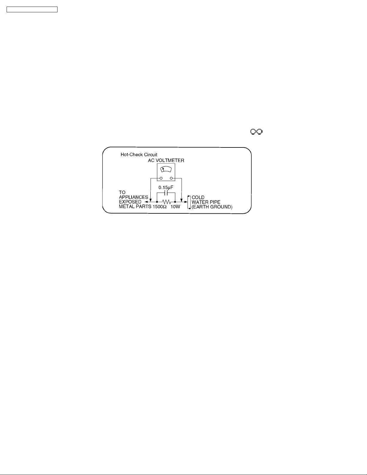
1.1.1. Leakage Current Cold Check
1. Unplug the AC cord and connect a jumper between the two prongs on the plug.
2. Measure the resistance value, with an ohmmeter, between the jumpered AC plug and each exposed metallic cabinet part on
the equipment such as screwheads, connectors, control shafts, etc. When the exposed metallic part has a return path to the
chassis, the reading should be between 1MW and 5.2MW.
When the exposed metal does not have a return path to the chassis, the reading must be
.
Figure 1
1.1.2. Leakage Current Hot Check (See Figure 1.)
1. Plug the AC cord directly into the AC outlet. Do not use an isolation transformer for this check.
2. Connect a 1.5kW, 10 watts resistor, in parallel with a 0.15µF capacitors, between each exposed metallic part on the set and a
good earth ground such as a water pipe, as shown in Figure 1.
3. Use an AC voltmeter, with 1000 ohms/volt or more sensitivity, to measure the potential across the resistor.
4. Check each exposed metallic part, and measure the voltage at each point.
5. Reverse the AC plug in the AC outlet and repeat each of the above measurements.
6. The potential at any point should not exceed 0.75 volts RMS. A leakage current tester (Simpson Model 229 or equivalent) may
be used to make the hot checks, leakage current must not exceed 1/2 milliamp. In case a measurement is outside of the limits
specified, there is a possibility of a shock hazard, and the equipment should be repaired and rechecked before it is returned to
the customer.
2
Page 3
TY-FB10WPE / TY-FB10WPU
2 Prevention of Electrostatic Discharge (ESD) to
Electrostatically Sensitive (ES) Devices
Some semiconductor (solid state) devices can be damaged easily by static electricity. Such components commonly are called
Electrostatically Sensitive (ES) Devices. Examples of typical ES devices are integrated circuits and some field-effect transistors and
semiconductor "chip" components. The following techniques should be used to help reduce the incidence of component damage
caused by electrostatic discharge (ESD).
1. Immediately before handling any semiconductor component or semiconductor-equipped assembly, drain off any ESD on your
body by touching a known earth ground. Alternatively, obtain and wear a commercially available discharging ESD wrist strap,
which should be removed for potential shock reasons prior to applying power to the unit under test.
2. After removing an electrical assembly equipped with ES devices, place the assembly on a conductive surface such as
aluminum foil, to prevent electrostatic charge buildup or exposure of the assembly.
3. Use only a grounded-tip soldering iron to solder or unsolder ES devices.
4. Use only an anti-static solder removal device. Some solder removal devices not classified as "anti-static (ESD protected)" can
generate electrical charge sufficient to damage ES devices.
5. Do not use freon-propelled chemicals. These can generate electrical charges sufficient to damage ES devices.
6. Do not remove a replacement ES device from its protective package until immediately before you are ready to install it. (Most
replacement ES devices are packaged with leads electrically shorted together by conductive foam, aluminum foil or comparable
conductive material).
7. Immediately before removing the protective material from the leads of a replacement ES device, touch the protective material
to the chassis or circuit assembly into which the device will be installed.
Caution
Be sure no power is applied to the chassis or circuit, and observe all other safety precautions.
8. Minimize bodily motions when handling unpackaged replacement ES devices. (Otherwiseham less motion such as thebrushing
together of your clothes fabric or the lifting of your foot from a carpeted floor can generate static electricity (ESD) sufficient to
damage an ES device).
3
Page 4
TY-FB10WPE / TY-FB10WPU
3 About lead free solder (PbF)
Note: Lead is listed as (Pb) in the periodic table of elements.
In the information below, Pb will refer to Lead solder, and PbF will refer to Lead Free Solder.
The Lead Free Solder used in our manufacturing process and discussed below is (Sn+Ag+Cu).
That is Tin (Sn), Silver (Ag) and Copper (Cu) although other types are available.
This model uses Pb Free solder in it’s manufacture due to environmental conservation issues. For service and repair work, we’d
suggest the use of Pb free solder as well, although Pb solder may be used.
PCBs manufactured using lead free solder will have the PbF within a leaf Symbol
Caution
· Pb free solder has a higher melting point than standard solder. Typically the melting point is 50 ~ 70 °F (30~40°C) higher.
Please use a high temperature soldering iron and set it to 700 ± 20 °F (370 ± 10 °C).
· Pb free solder will tend to splash when heated too high (about 1100 °F or 600 °C).
If you must use Pb solder, please completely remove all of the Pb free solder on the pins or solder area before applying Pb
solder. If this is not practical, be sure to heat the Pb free solder until it melts, before applying Pb solder.
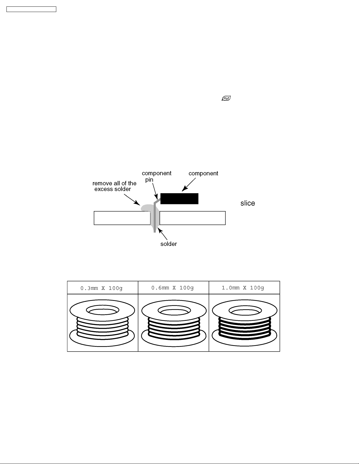
· After applying PbF solder to double layered boards, please check the component side for excess solder which may flow onto
the opposite side. (see figure below)
Suggested Pb free solder
There are several kinds of Pb free solder available for purchase. This product uses Sn+Ag+Cu (tin, silver, copper) solder.
However, Sn+Cu (tin, copper), Sn+Zn+Bi (tin, zinc, bismuth) solder can also be used.
stamped on the back of PCB.
4
Page 5
TY-FB10WPE / TY-FB10WPU
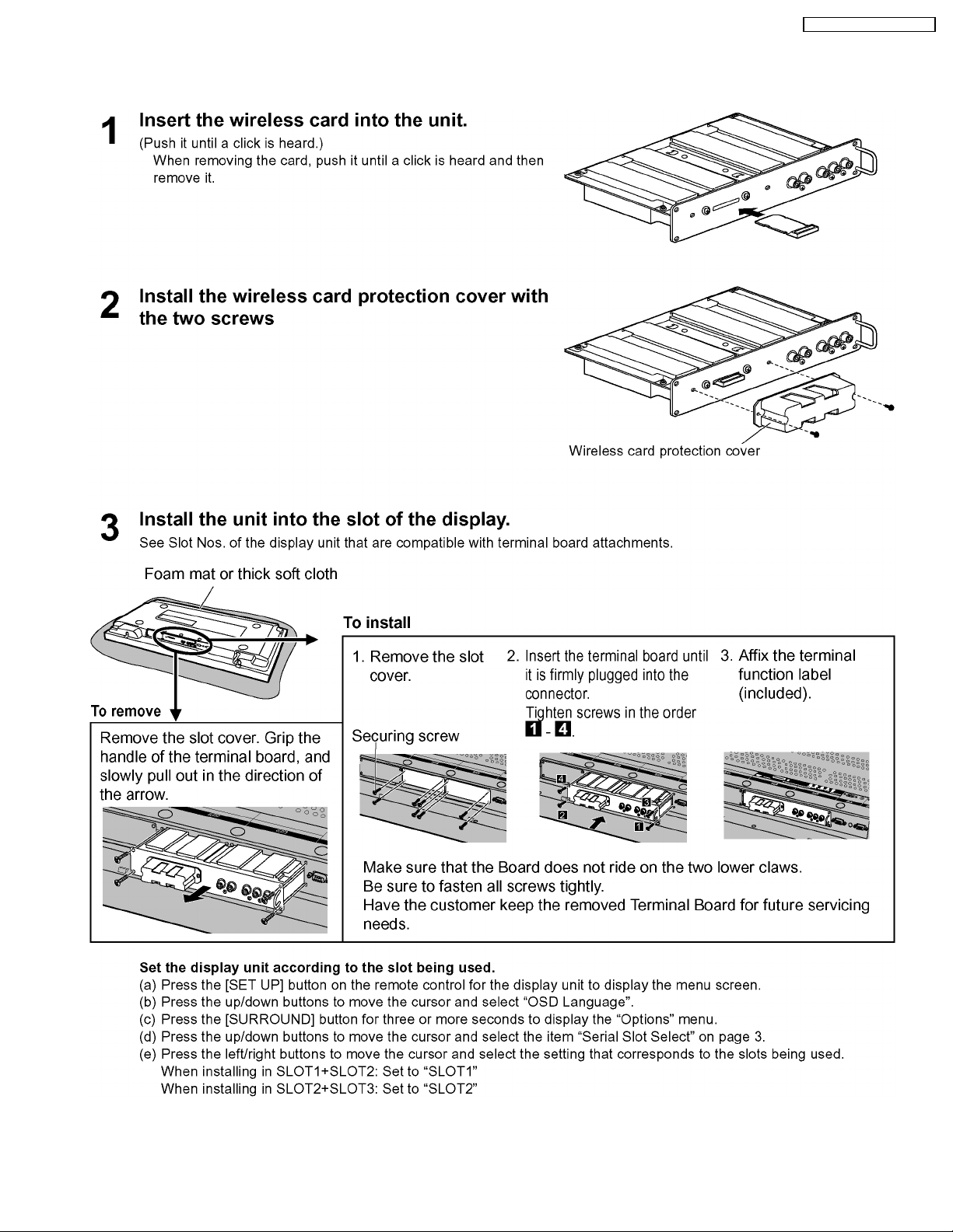
4 Installing and removing the wireless card/Installing and
removing the unit to the display
5
Page 6

TY-FB10WPE / TY-FB10WPU
NOTE
6
Page 7
5 Circuit Board Layout
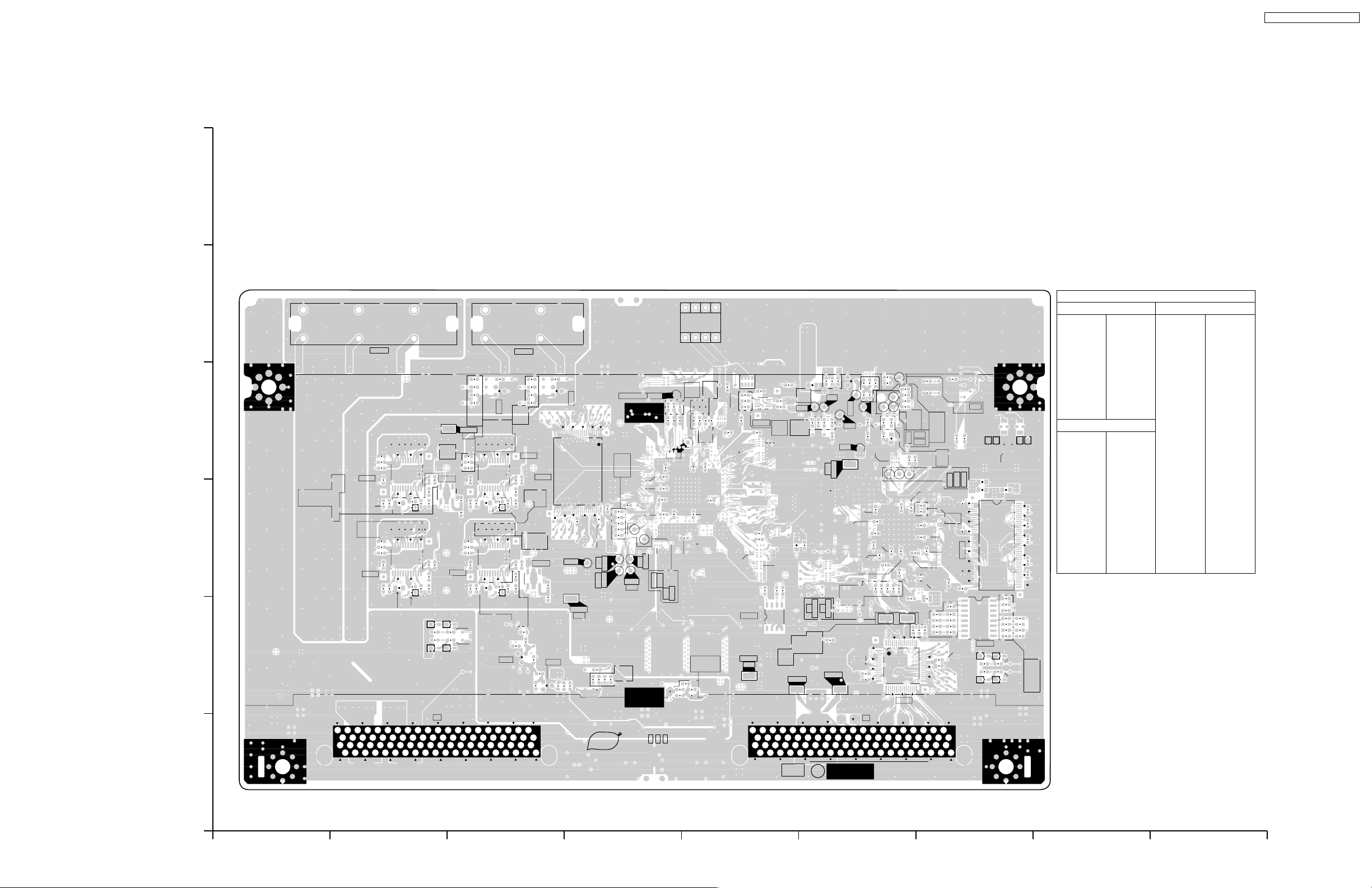
5.1. HW-Board
6
HW-BOARD (FOIL SIDE)
TXNHW1WFTE (TY-FB10WPE)
TXNHW1WFTU (TY-FB10WPU)
5
GR
4
C930
C929
D922
3
2
1
R928
B40
C931
R930R931
B39
A40
R929
A39
B
R922
R923
R925
IC921
R943
R945
C947
R944
R942
IC941
R926
JK302
R927
C945
C946
C944
R946
RL
C924
C925
C926
C927
C950
D942
D851
R857
R858
D853
1
1
R948
C923
C943
C951
R951
IC922
5
1
R949
R950
H2
R924
12
C928
13 24
12
C948
13 24
R947
C949
R962
R963
R965
R983
D854
R982
R985
IC981
3
4
TP901
R993
C934
D852
C881
R885
R886
R887
GND
12
C968
13 24
R966
R967
12
C988
13 24
R986
R987
R855
R856
C989
R964
C969
C967
C966
C990
D982
Q881
C965
Q721
R882
C964
R702
C963
1
1
R742
C891
R895
R896
R897
R988
JK303
IC961
C971
R971
C991
R989
5
1
R969
R970
R990
R991
C970
D962
R984
C987
B2
A2
IC361
C986
IC982
R741
R744
R745
A1
C985
B1
R
R968
25
C984
4
3
R743
24
C983
Q722
R994
C994
R892
TP13
C731
Q891
TP851
GND
C732
R746
C363
C364
R708
1
TCK
TRST
C716
R424
R421
R426
R427
R435
R445
48
TP22
TP25
PbF
CPU HOLD
C405
C406
R459
C415
TP23
TMS
R705
R706
R707
C715
TY-FB10WPE / TY-FB10WPU
Parts Location
8
5
IC
D503
C653C654C655C656
IC3361 C-4
IC3502 E-4
IC3504 E-2
IC3506 G-2
IC3602 G-3
IC3801 F-2
IC3921 B-4
IC3922 B-4
IC3941 B-3
IC3961 C-4
IC3981 C-3
IC3982 C-3
TRANSISTOR
Q3721 C-2
Q3722 C-2
Q3881 C-4
Q3891 D-4
SW501
14
R374
R557
C553
C411
C410
R447
R446
R510
R452
R513
IC504
TP801
GND
R450
B40
C554
5
8
IC502
R458
R451
C555
8
14
B39
4
R539
R540
C526
R553
TP28
R409
R430
TP27
C414
C412
R420
R417
TDI
TP24
TP11
HRST
TDO
TP21
C726
C416
R429
R440
C404
R431
R727
R726
R437
R419
R728
R522
C403
C417
R521
R524
C725
R725
R523
R536
C413
R515
R512
R509
1
R538
R558
R448
R453
R541
R504
C812
5
C813
R312
L501
R559
R568
R569
R570
R571
C806
TP703
TP7
R314
C301
R313
R331
R301
R315
R302
C502
VD
C559
R572
R573
R574
R575
TP803
R633
HD
TP702
TP1
GND
R621
TP802
C304
TP3
TP601
R624
R661
D301
TP2
C610
R627
R626
C809
TP10
R602
C611
C604
R628
C808
R802
C308
C605
R635
H1
C617
C616
R614
R605
1
16
TP4
R316
17
64
C309
C615
C310
C609
IC801
R320
C311
R329
R319
R606
TP5
R615
C620
TP6
TP8
32
C607
C524
C523
C621
C619
R651
R616
L603
48
R529
R310
TP9
R309
R311
R321
R330
R534
R535
TP33
IC602
8
D801
R807
R808
FL501
D502
D501
C602
L601
1
43
16
IC506
D802
D803
D804
R322
C312
R317
R318
TP31
TP32
C660
C618
C608
C659
C606
C603
C658
C614
R603
C657
1
49
R803
R804
33
B2
B1
9
R532
L651
R533
R805
R806
86
D504
R583
R582
R580
C558
R588
R589
R587
R586
R585
R584
FL502
C651
44
R581
HW-BOARD (FOIL SIDE)
TP
TP3001 F-4
TP3002 F-4
TP3003 F-4
TP3004 F-4
TP3005 F-4
TP3006 G-4
TP3007 F-4
TP3008 G-4
TP3009 G-4
TP3010 F-4
TP3011 D-3
TP3013 D-3
TP3021 D-3
TP3022 D-3
TP3023 D-3
TP3024 D-3
TP3025 D-3
TP3027 D-4
TP3028 D-4
TP3031 G-4
TP3032 G-4
TP3033 G-4
TP3501 F-4
TP3702 F-2
TP3703 E-2
TP3801 E-2
TP3802 F-2
TP3803 F-2
TP3851 D-3
TP3901 C-4
CR NO.3
NO.
ORDER
A40
A39
HWA
1
A2
TNPA4264
A1
TY-FB10WPE
HW-BOARD TXNHW1WFTE
ABCDEFGH I
TY-FB10WPU
HW-BOARD TXNHW1WFTU
TY-FB10WPE
HW-BOARD TXNHW1WFTE
TY-FB10WPU
HW-BOARD TXNHW1WFTU
7
Page 8
TY-FB10WPE / TY-FB10WPU
6
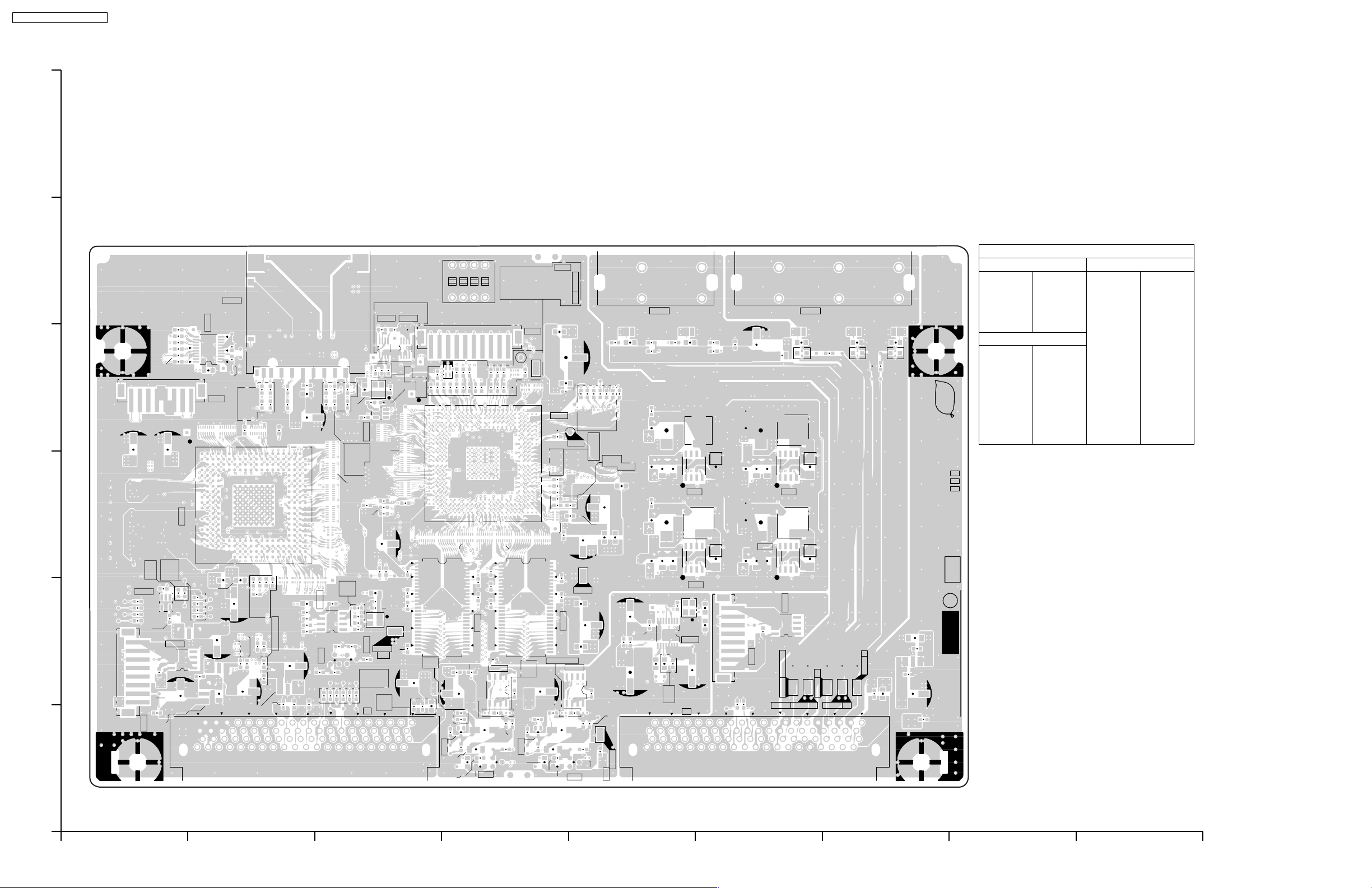
HW-BOARD (COMPONENT SIDE)
TXNHW1WFTE (TY-FB10WPE)
TXNHW1WFTU (TY-FB10WPU)
5
4
3
2
1
Parts Location
ON
5
SW501
JK301
IC501
11
R527
R525
R528
R526
4
5
C601
R564
R565
R566
R567
IC802
8
A1A2B1B2
R531
1
5
C815
IC601
20
C525
A
L602
4
8
1
R612
1
C613
C805
R530
1
C652
R562
R563
C556
IC505
3
R579
R578
R577
R576
C557
FL803
8
R809
C904
1
H307
C814
FL804
H306
C816
C612
110
R611
C801
C521
C802
FL801
C522
R308
R328
R604
10
R307
R327
C811
FL802
8
R632
R634
R631
C807
R630
R801
R306
R326
C305
R613
R601
C307
R617 R618
R619
R620
R629
C901
C804
C810
C661
C662
R664
R665
C902
L661
C903
C306
R622
IC603
R663
5
8
C803
R904
Q901
R902 R903
1
R610
R625
9
R608
R607
R662
C665
R667
C527
R305
R325
R623
4
1
R304
R324
R609
R454
R666
R905
X371
L371
C303
C501
C664
4
R544
R303
R323
R502
R907
IC503
C302
Q902
R593
H1
1
L662
R719
R591
C372
8
5
R507
R503
R560
TP501
R590
R373
IC371 IC372
5
8
4
1
C371
C528
R455
3
1
R456
R457
R505
R501
C343
R561
C344
C663
X602
C346
GND
R739
R592
B40
C905
C911
L901
B39
A40
A39
5
R371
1
C345
C912
C373
R508
R506
27
4
R372
A
R375
R414
C728
R748
1
1
R413
R418
C712
R733
Q724
C729
R738
R736
1
234
1
R704
R703
R734
R737
54
C348
28
R416
C350
C347
IC341
C727
Q711
8
R443
D505
R543
R556
TP26
R432
R436
R439
R514
R594
R555
R442
R449
R511
R542
R554
R537
4
H305
10
R402
R412
C349
R415
1
C351
C352
27
C723
C724
IC703
4
5
R735
R730
1
R729
8
C718
R747
R713
R732
NP
R731
Q723
R714
C730
R718
R595
R411
R716
R438
R403
C711
R441
C714
R434
L402
C409
IC401
R410
R404
54
R717
R401
R428
R551
5
C401
IC342
C342
28
4
R433
R444
R425
R422
C354
C353
R710
IC702
C719
Q701
TP12
C402
TP401
GND
C408
R361
R406
TP341
C341
L341
NP
C717
R715
C720
R362
R405
R408
1
R709
8
C407
R366
R407
C713
L703
R363
C361
C551
L401
L891
R364
R423
R552
C704
R711
GND
R367
C705
C703
R712
TP701
R365
C552
C362
L361
R891
L702
R972
C706
B1
A1
R893
R961
R992
R981
JK303
R894
C973
C993
8
C710
9
B2
A2
C981
C961
C709
L881
C962
C982
C708
+
C972
+
C992
R701
1
16
R881
X701
IC701
H2
Q961
Q981
C707
C702
L701
C921
C952
8
1
C907
C941
H308
C932
C922
Q941
C942
R859
5
8
L851
+
+
R
C851
TP874
FL873
Q921
IC852
R898
AUDIO L
TP875
AUDIO R
JK302
14
LR
R884
C852
R883
C933
R932
L961
D961
R921
C953
R952
L981
R941
D981
C701
C906
L921
D921
L941
D941
R888
R873
JS855
Pr
TP873
JS856
TP872
B
JS854
Pb
A39
FL872
B39
JS853
JS852
A40
Y
TP871
B40
GR
R871R872
FL871
JS851
PbF
SEE REVERSE FOR ORDER NO.
C856
C855
FL854
C910
R901
C909
C854
C908
IC
TRANSISTOR
CR NO.3
HWA
1
TNPA4264
HW-BOARD (COMPONENT SIDE)
IC3603 C-2
IC3701 E-2
IC3702 E-2
IC3703 D-2
IC3802 A-2
IC3852 F-2
Q3701 E-1
Q3711 D-1
Q3723 D-1
Q3724 D-1
Q3901 C-2
Q3902 C-2
Q3921 F-3
Q3941 F-3
Q3961 E-3
Q3981 E-2
TP
TP3012 E-4
TP3026 D-5
TP3341 E-2
TP3401 E-5
TP3501 C-2
TP3701 E-1
TP3871 G-2
TP3872 G-2
TP3873 F-2
TP3874 F-2
TP3875 F-2
TY-FB10WPE
HW-BOARD TXNHW1WFTE
ABCDEFGH I
TY-FB10WPU
HW-BOARD TXNHW1WFTU
TY-FB10WPE
HW-BOARD TXNHW1WFTE
TY-FB10WPU
HW-BOARD TXNHW1WFTU
8
Page 9

6 Block and Schematic Diagram
6.1. Schematic Diagram Notes
TY-FB10WPE / TY-FB10WPU
9
Page 10

TY-FB10WPE / TY-FB10WPU
6.2. HW-Board Block Diagram
WIRELESS
CARD
SLOT
FOR
FACTORY
USE
TXD0
RXD0
JK3301
11
H3306
7
8
9
1
2
3
4
5
6
7
8
10
D.SW
12
W.P.
+3.3V_B
+3.3V_B
Q3981
+1.8V
D2 D2 D1 D1
SDDAT2
SDDAT3
SDDAT0
SDDAT1
IC3361
FLASH ROM
32Mbit
133MHz
IC3341,42
SDRAM
128bitx2
+3.3V_B
X3371
66MHz
3
OUT4VDD
1OE2
GND
+3.3V_B
IC3371
CPG
8
VCC
2
5
18
2
3
IC3372
CK VCC
D
Q-
D3505
G
SD
R
FR
6
3
+3.3V_B
5
Q
S1G1S2G2
IC3981
DC-DC CONV.
19
OUT-1
16
OUT-2
21
VIN
VDD
VCC
CTL
+1.4V
17
5
9
Q3961
D2 D2 D1 D1
+3.3V_B
IC3401
FR-V(FPGA)
+1.4V
6.144MHz
SDDAT0-3
SDCMD
SDCLK
SDCD
AUDIOCK
BCK0
LRCK0
AUDIO_PWDN
AUDIO_MUTE
SD0
1
MCLK
2
BICK
3
SDTI
4
LRCK
5
PDN
6
SMUTE
AUDIO DAC
SDWP
FRV_IR
FRV_TXD1
FRV_RXD1
IC3504
EEPROM
DCLK
SDA(1) SDA
SCL(1)
VDG(0)-(7)
VDB(0)-(7)
VDR(0)-(7)
VDHSYNC
VDVSYNC
VDCLKOUT
6
85
VCC
SCL
ICHIP_RST RSTB
IC3505
RESET
VDCLKIN
CLKIN
SDCKI
PRST
1
+3.3V_B
RST VDD
2
IC3602
SDRAM(64M)
+3.3V_B
FRV_TXD0
FRV_RXD0
SDLED
FRLED
FRV_TEST2
FRV_TEST3
SW3501
1234
LVDS_RST
S1G1S2G2
X3701
3
OUT4VDD
GND
IC3701
+3.3V_B
+3.3V_B
SW3501
1:2:RAM TEST
3:4:LVDS_FB
+3.3V_B
1OE2
AOUTL
AOUTR
+3.3V_B
GND
TP3401
VDD
IC3961
DC-DC CONV.
19
OUT-1
16
OUT-2
SLOT+5V
14
11
10
+1.8V
21
VIN
17
VDD
5
VCC
9
CTL
ICHIPG0-G7
ICHIPB0-B7
ICHIPR0-R7
ICHIPHSYNC
ICHIPVSYNC
ICHIPCLK
TRST
SLOT+9V
SLOT+9V
IC3601
ICHIPS
5
6
3
2
5
6
3
2
+3.3V_B
IC3702
EQ-L
+
-
+
-
IC3703
EQ-R
+
-
+
-
G(0-9)
B(0-9)
R(0-9)
POCLK
MCLK
VD
8
7
1
8
7
1
SLOT+9V
SLOT+9V
Q3721
10bit
10bit
10bit
Q3941
S1G1S2G2
D2 D2 D1 D1
SLOT+5V
Q3722
TP3802 TP3803
IC3941
DC-DC CONV.
VIN
19
OUT-1
VDD
VCC
16
OUT-2
CTL
Q3723
Q3724
6
8
62
G(0-9)
63
40
46
9
11
64
B(0-9)
1
48
54
4
5
39
R(0-9)
61
33
38
VDHD
55
HDHD
57
VD
13
PWRDWN
60
LVDS_FB
CLKIN
12
IC3603
CPG
VDD
CLK5
31
CLK1 FIN
IC3982
AVR+5V
1
21
17
+3.3V_B
5
9
VOUT VDD
Q3921
D2 D2 D1 D1
5
IC3921
DC-DC CONV.
S1G1S2G2
19
16
OUT-1
OUT-2
21
VIN
17
VDD
5
VCC
9
CTL
Q3902
Q3901
IC3922
AVR+5V
1
VOUT VDD
STB+5V
5
SLOT+9V
SLOT+5V
GND
TP3901
TO SLOT
H1
A40 LAN+14V
B40 LAN+14V
A21 SLOT+9V
SLOT+9V
B21
A19 SLOT+5V
SLOT+5V
B19
B28 PLUG_DET
Q3701
BUFFER
Q3711
BUFFER
GND
TP3501
IC3503
+3.3V_B
INV.
IC3502
3.3V<->5V
5
2
8
STB+5V
4
26
53
A26
AUDIO_L
A28
AUDIO_R
REMOTEB30
RXDB26
TXDB27
68
LVDS TX
+3.3V_B
IC3801
PLL
PARALLEL TO SERIAL
X3602
65MHz
3
OUT4VDD
GND
+3.3V_B
1OE2
TXA1
TXA0
8
5
6
7
TP3872
Q3701
BUFFER
TXB1
TXB0
TXC1
TXC0
TXD1
TXD0
TXE1
TXE0
TXCLK1
TXCLK0
SLOT+9V
PrPbY
TP3873
AUDIO R AUDIO L
TP3874
TP3875
+3.3V_B
VCC
30
31
30
31
30
31
30
31
30
31
30
31
TXA1
TXA0
TXB1
TXB0
TXC1
TXC0
TXD1
TXD0
TXE1
TXE0
TXCLK1
TXCLK0
IC3802
SLOT CONFIG
EEPROM
VCC
SDA
SCL
WP
TP3871
GR
GR
JK3302
COMPONENT
VIDEO IN
JK3303
AUDIO IN
GR-G
B
B
B-G
R
R
R-G
L
L-G
R
R-G
Q3701
BUFFER
H3306
1
STB+5V
2
SRQ
6
SCL
7
SDA
8
WP
H2
A21 SLOT+9V
A38
TXA0B3
TXA1B2
TXB0B6
TXB1B5
TXC0B9
TXC1B8
TXD0B15
TXD1B14
TXE0A3
TXE1A2
TXCLK0B12
TXCLK1B11
STB+5VA22
IIC_DATB24
IIC_SCLB25
SRQB23
FOR
FACTORY USE
TO SLOT
Y/G
PB/BA36
PR/RA34
AUDIO_RA28
AUDIO_LA26
PLUG_DETB28
TY-FB10WPE/U
HW-Board Block Diagram
TY-FB10WPE/U
HW-Board Block Diagram
10
Page 11

6.3. HW-Board (1 of 5) Schematic Diagram
A
!
HW-BOARD (1/5)
TXNHW1WFTE(TY-FB10WPE)
TXNHW1WFTU(TY-FB10WPU)
B
C
R3301
0
C3307
47u
16V
R3309
0
R3302
0
WIRELESS CARD
INTERFACE
JK3301
+
C3306
0.1u
16V
TP9
D.SW
11
W.P.
35
K1NA09E00080
TY-FB10WPE / TY-FB10WPU
1
2
CMODE
1
3
0
2
L
H
H
N.C/RFU
L
L
H
54
VSS
53
DQ15
52
VSSQ
51
DQ14
50
DQ13
49
VDDQ
48
DQ12
47
DQ11
46
VSSQ
45
DQ10
44
DQ9
43
VDDQ
42
DQ8
41
VSS
40
39
<--
UDQM
38
<--
CLK
37
CKE
36
N.C
35
A11
34
A9
33
A8
32
A7
31
A6
30
A5
29
A4
28
VSS
L 266MHz
H
DCLK DCLK
C3342
L3341
47u
J0JHC0000075
C3341
10u
6.3V
DDQ0
DDQ1
DDQ2
DDQ3 DDQ19
DDQ4
C3344
R3318
R3331
C3301
0
0.1u
16V
TP7
9
TP1
1
TP2
2
3
TP3
4
TP4
5
6
TP5
7
TP6
8
TP8
10
TP10
12
R3312
10k
R3303
68
R3304
68
R3305
68
C3305
10u
6.3V
R3306
0
R3307
68
R3308
68
R3311
C3302
100
33p
50V
R3316
10k
10k
R3317
R3319
R3313
R3315
10k
10k
10k
R3321
10k
10k
R3323
0
R3324
0
R3325
0
R3326
0
R3327
0
R3328
0
R3329
0
R3330
C3312
C3311
16V
0.1u
0
16V
0.1u
SDDAT2
SDDAT3
SDDAT0
SDDAT1
SDCMD
SDCLK
SDCD
SDWP
DDQ5
DDQ6
DDQ7
DDQM3
DWE
DCAS
DRAS
DCS0
DBA0
DBA1
DA10
DA0
DA1
DA2
DA3
0.1u
16V
C3345
0.1u
16V
SDRAM(128BIT)
16V
+
IC3341
C3ABQG000083
C3343
0.1u
16V
1
VDD
2
DQ0
3
VDDQ
4
DQ1
5
DQ2
6
VSSQ
7
DQ3
8
DQ4
9
VDDQ
10
DQ5
11
DQ6
12
VSSQ
13
DQ7
14
VDD
15
-->
LDQM
16
-->
WE
17
-->
CAS
18
-->
RAS
19
CS
20
BA0
21
BA1
22
A10/AP
23
A0
24
A1
25
A2
26
A3
27
VDD
C3346
0.1u
16V
CORE
133MHz
133MHz
DSU
COREEX-BUS
BUS
33MHz
DDQ16
DDQ17
DDQ18
DDQ20
DDQ21
DDQ22
DDQ23
DDQM1
DWE
DCAS
DRAS
DCS0
DBA0
DBA1
DA10
DA0
DA1
DA2
DA3
400MHz
C3350
0.1u
16V
C3351
0.1u
16V
SDRAM(128BIT)
22MHz
IC3342
C3ABQG000083
C3349
0.1u
16V
1
VDD
2
DQ0
3
VDDQ
4
DQ1
5
DQ2
6
VSSQ
7
DQ3
8
DQ4
9
VDDQ
10
DQ5
11
DQ6
12
VSSQ
13
DQ7
14
VDD
15
-->
LDQM
16
-->
WE
17
-->
CAS
18
-->
RAS
19
-->-->
CS
20
BA0
21
BA1
22
A10/AP
23
A0
24
A1
25
A2
26
A3
27
VDD
C3352
0.1u
16V
N.C/RFU
VSS
DQ15
VSSQ
DQ14
DQ13
VDDQ
DQ12
DQ11
VSSQ
DQ10
DQ9
VDDQ
DQ8
VSS
UDQM
CLK
CKE
N.C
A11
A9
A8
A7
A6
A5
A4
VSS
TP3341
54
DDQ31
53
52
DDQ30
51
DDQ29
50
C3354
0.1u
49
16V
DDQ28
48
DDQ27
47
46
DDQ26
45
DDQ25
44
C3353
0.1u
43
16V
DDQ24
42
41
40
DDQM0
39
<--
<--
38
37
36
35
34
33
32
31
30
29
28
DCKE
<--<--
DA11
DA9
DA8
DA7
DA6
DA5
DA4
SDRAM
133MHz-->
66MHz
133MHz
66MHz
DDQ15
DDQ14
DDQ13
C3348
0.1u
16V
DDQ12
DDQ11
DDQ10
DDQ9
C3347
0.1u
16V
DDQ8
DDQM2
DCKE
DA11
DA9
DA8
DA7
DA6
DA5
DA4
D
3
4
L3361
J0JHC0000075
1OE2
C3371
0.1u
25V
E
FRV CLOCK GENERATOR
IC3371
C0JBAZ002217
1
2
3
45
FRV CLOCK GENERATOR
IC3372
C0JBAF000548
1
F
CK
2
D
3
Q~
4
GND
<--
3
OUT4VDD
R3371
33
GND
C3372
0.1u
16V
8
7
6
R3374
47
R3375
56
8
VCC
PR~
CLR~
C3373
0.1u
7
16V
6
R3373
68
5
Q
66MHz
X3371
L3371
H1A6605B0012
J0JHC0000075
ROM_A16
ROM_A15
ROM_A14
ROM_A13
ROM_A12
ROM_A11
ROM_A10
ROM_A9
ROM_A20
ROM_A21
ROM_WE
ROM_A19
ROM_A18
ROM_A8
ROM_A7
ROM_A6
ROM_A5
ROM_A4
ROM_A3
ROM_A2
TY-FB10WPE/U
HW-Board (1 of 5) Schematic Diagram
+
C3362
C3361
16V
6.3V
47u
10u
R3361
0
1
A15
2
A14
3
A13
4
A12
5
A11
6
A10
7
A9
8
A8
9
A19
(A21)
10
A20
11
WE#
R3366
12
RESET#
10k
13
NC
(ACC)
14
WP#/ACC
10k
R3367
15
RY/BY#
16
A18
17
A17
18
A7
19
A6
20
A5
21
A4
22
A3
23
A2
24
A1
IC3361
C3FBND000289
48
A16
47
(VCCQ)
BYTE#
46
VSS
45
(DQ15)
DQ15/A-1
44
DQ7
43
DQ14
42
DQ6
41
DQ13
40
DQ5
39
DQ12
38
DQ4
37
VCC
36
<A21>
DQ11
35
(WP#)
DQ3
34
(A19)
DQ10
33
DQ2
32
DQ9
31
DQ1
30
DQ8
29
DQ0
28
<--
OE#
27
VSS
26
<--
CE#
25
A0
C3364
0.1u
16V
C3363
0.1u
16V
ROM_CS_FLASH
ROM_A17
ROM_D31
ROM_D23
ROM_D30
ROM_D22
ROM_D29
ROM_D21
ROM_D28
ROM_D20
ROM_D27
ROM_D19
ROM_D26
ROM_D18
ROM_D25
ROM_D17
ROM_D24
ROM_D16
ROM_DIR
ROM_A1
FLASH ROM(32Mbit)
5
6
TY-FB10WPE/U
HW-Board (1 of 5) Schematic Diagram
1
24
5
7
8
936
11
Page 12

TY-FB10WPE / TY-FB10WPU
6.4. HW-Board (2 of 5) Schematic Diagram
1
2
IC3401
<-->
<--
R3415
R3416
R3417
R3418
-->
<-->
R3419
133MHz
<-<-<-<--
<-<-<-<-<--
B18 A[31]
IC3401 B20 A[30]
IC3401 C20 A[29]
IC3401 D20 A[28]
IC3401 E20 A[27]
IC3401 A21 A[26]
IC3401 B21 A[25]
IC3401 C21 A[24]
IC3401 A22 A[23]
IC3401 B22 A[22]
IC3401 C22 A[21]
IC3401 D22 A[20]
IC3401 C23 A[19]
IC3401 D23 A[18]
IC3401 D24 A[17]
IC3401 D25 A[16]
IC3401 E24 A[15]
IC3401 E25 A[14]
IC3401 E26 A[13]
IC3401 F22 A[12]
IC3401 F23 A[11]
IC3401 F24 A[10]
IC3401 F25 A[9]
IC3401 F26 A[8]
IC3401 G24 A[7]
IC3401 G25 A[6]
IC3401 G26 A[5]
IC3401 H22 A[4]
IC3401 H23 A[3]
IC3401 H24 A[2]
IC3401 J24 BE[2]
IC3401 H25 BE[3]
IC3401 J25 BE[1]
IC3401 J26 BE[0]
IC3401 K22 D[31]
IC3401 K23 D[30]
IC3401 K24 D[29]
IC3401 K25 D[28]
IC3401 K26 D[27]
IC3401 L24 D[26]
IC3401 L25 D[25]
IC3401 L26 D[24]
IC3401 M22 D[23]
IC3401 M23 D[22]
IC3401 M24 D[21]
IC3401 M25 D[20]
IC3401 M26 D[19]
IC3401 N24 D[18]
IC3401 N25 D[17]
IC3401 N26 D[16]
IC3401 P26 D[15]
IC3401 P25 D[14]
IC3401 P24 D[13]
IC3401 P23 D[12]
IC3401 P22 D[11]
IC3401 R26 D[10]
IC3401 R25 D[9]
IC3401 R24 D[8]
IC3401 T26 D[7]
IC3401 T25 D[6]
IC3401 T24 D[5]
IC3401 T23 D[4]
IC3401 T22 D[3]
IC3401 U26 D[2]
IC3401 U25 D[1]
IC3401 U24 D[0]
IC3401 E17 DIR
IC3401 B17 WE#
IC3401 C17 RD#
IC3401 D17 RDY#
R3409
10k
IC3401 H26 BCLKO
IC3401 AF17 DBA[1]
IC3401 AD16 DBA[0]
IC3401 AD17 DA[12]
IC3401 AE17 DA[11]
IC3401 AE16 DA[10]
IC3401 AF16 DA[9]
IC3401 AB15 DA[8]
IC3401 AC15 DA[7]
IC3401 AD15 DA[6]
IC3401 AE15 DA[5]
IC3401 AF15 DA[4]
IC3401 AD14 DA[3]
IC3401 AE14 DA[2]
IC3401 AF14 DA[1]
IC3401 AF13 DA[0]
IC3401 AF18 DDQM[3]
IC3401 AB17 DDQM[2]
IC3401 AC11 DDQM[1]
IC3401 AB11 DDQM[0]
IC3401 AD13 DCS#[3]
IC3401 AD11 DCS#[0]
IC3401 AE13 DRAS#
IC3401 AC17 DCKE
IC3401 AF10 DCAS#
IC3401 AE10 DWE#
IC3401 AF11 DCS#[2]
IC3401 AE11 DCS#[1]
IC3401 AC12 DCLK
10
IC3401 AE12 DCLKFB
R3420
1k
IC3401
C2GBC0000205
FR-V(MB93461)
ROM_A22
ROM_A21
ROM_A20
ROM_A19
ROM_A18
ROM_A17
ROM_A16
ROM_A15
ROM_A14
ROM_A13
ROM_A12
ROM_A11
ROM_A10
ROM_A9
ROM_A8
ROM_A7
ROM_A6
ROM_A5
ROM_A4
ROM_A3
ROM_A2
ROM_A1
R3404
10k
ROM_D31
ROM_D30
ROM_D29
ROM_D28
ROM_D27
ROM_D26
ROM_D25
ROM_D24
ROM_D23
ROM_D22
ROM_D21
ROM_D20
ROM_D19
ROM_D18
ROM_D17
ROM_D16
ROM_DIR
ROM_WE
3
4
R3411
EXB2HV220JV
DDQ31
IC3401 AE22 DDQ[31]
DDQ30
IC3401 AF22 DDQ[30]
DDQ29
IC3401 AB21 DDQ[29]
DDQ28
IC3401 AC21 DDQ[28]
DDQ27
IC3401 AD21 DDQ[27]
DDQ26
IC3401 AE21 DDQ[26]
DDQ25
IC3401 AF21 DDQ[25]
DDQ24
IC3401 AD20 DDQ[24]
R3412
EXB2HV220JV
DDQ23
IC3401 AE20 DDQ[23]
DDQ22
IC3401 AF20 DDQ[22]
DDQ21
IC3401 AB19 DDQ[21]
DDQ20
IC3401 AC19 DDQ[20]
DDQ19
IC3401 AD19 DDQ[19]
DDQ18
IC3401 AE19 DDQ[18]
DDQ17
IC3401 AF19 DDQ[17]
DDQ16
IC3401 AE18 DDQ[16]
R3413
EXB2HV220JV
DDQ15
IC3401 AD10 DDQ[15]
DDQ14
IC3401 AF9 DDQ[14]
DDQ13
IC3401 AE9 DDQ[13]
DDQ12
IC3401 AD9 DDQ[12]
DDQ11
IC3401 AC9 DDQ[11]
DDQ10
IC3401 AB9 DDQ[10]
DDQ9
IC3401 AF8 DDQ[9]
DDQ8
IC3401 AE8 DDQ[8]
R3414
EXB2HV220JV
DDQ7
IC3401 AF7 DDQ[7]
DDQ6
IC3401 AE7 DDQ[6]
DDQ5
IC3401 AD7 DDQ[5]
DDQ4
IC3401 AC7 DDQ[4]
DDQ3
IC3401 AB7 DDQ[3]
DDQ2
IC3401 AF6 DDQ[2]
DDQ1
IC3401 AE6 DDQ[1]
DDQ0
IC3401 AD6 DDQ[0]
5
6
DBA1
DBA0
DA11
DA10
DA9
DA8
DA7
DA6
DA5
DA4
DA3
DA2
DA1
DA0
DDQM3
DDQM2
DDQM1
DDQM0
DCS0
DRAS
DCKE
DCAS
DWE
EXB2HV220JV
EXB2HV220JV
EXB28V220JX
EXB2HV220JV
<--
TY-FB10WPE/U HW-Board (2 of 5) Schematic Diagram
R3424
10k
R3426
10k
R3427
10k
TCK
TDO
TDI
TMS
FRV_RST
ED
ECLK
ECV
ERST
ICHIP_CLK_F
ICHIP_ENB_F
ICHIP_WR_F
ICHIP_RD_F
FRV_PANEL
SDLED
AUDIO_PWDN_F
AUDIO_MUTE_F
FRLED
FRV_TXD1
FRV_RXD1
ICHIP_RST_F
LVDS_RST_F
FRV_TXD0
FRV_RXD0
FRV_IR
FRV_TEST1
FRV_IRQ
FRV_TEST2
FRV_IR
FRV_TEST3
ROM_CS_FLASH
CPUHOLD
FRV_RST
-->
<--
-->
-->
-->
<->
<--
-->
-->
33MHz
11
12
L3401
J0JHC0000075
C3401
IC3401 W26 CMODE[3]
IC3401 W25 CMODE[2]
IC3401 W24 CMODE[1]
IC3401 W23 CMODE[0]
IC3401 Y24 RAMBOOT#
-->
-->
-->
R3423
0
R3429
R3432
R3434
10k
10k
R3442
R3444
R3446
R3428
0
-->
-->
<-<-<--
-->
TP11
HRST
<--
<--
-->
<--
-->
<--
-->
R3441
0
<--
<-<--
-->
0
0
0
DIR
L
H
IC3401 B19 IBW
IC3401 AC23 MTESTMODE
IC3401 AE23 TESTMODE
IC3401 AD23 TDC
IC3401 AB23 TCK
IC3401 AC24 TDO
IC3401 AB24 TDI
IC3401 AB25 TMS
IC3401 AB26 TRST#
IC3401 D19 ERR#
IC3401 C19 BREQ#
IC3401 C16 BGNT#
IC3401 A17 BS#
IC3401 A19 BSTREQ#
IC3401 A18 BSTACK#
IC3401 AA23 HRST#
IC3401 AA25 ED
IC3401 Y22 ECLK
IC3401 AA22 ECV
IC3401 AA24 ERST#
IC3401 C9 PP[21]
IC3401 B9 PP[20]
IC3401 D10 PP[19]
IC3401 C10 PP[18]
IC3401 A9 PP[17]
IC3401 B8 PP[16]
IC3401 B10 PP[15]
IC3401 E10 PP[14]
IC3401 A8 PP[13]
IC3401 A10 PP[12]
IC3401 C11 PP[11]
IC3401 B11 PP[10]
IC3401 A11 PP[09]
IC3401 E12 PP[08]
IC3401 D12 PP[07]
IC3401 C12 PP[06]
IC3401 B12 PP[05]
IC3401 A12 PP[04]
IC3401 C13 PP[03]
IC3401 B13 PP[02]
IC3401 A13 PP[01]
IC3401 A14 PP[00]
IC3401 C14 CS#[7]
IC3401 A15 CS#[6]
IC3401 B15 CS#[5]
IC3401 C15 CS#[4]
IC3401 D15 CS#[3]
IC3401 E15 CS#[2]
IC3401 A16 CS#[1]
IC3401 B16 CS#[0]
IC3401 B14 CPUHOLD
IC3401 U23 RSTOUT#
IC3401 Y26 PRST#
IC3401 B6 SDCKI
IC3401 V25 CLKIN
IC3401 Y5 VDPCLKIN
Dx
MODE
READ
INPUT
OUTPUT
WRITE
TP13
R3422
0
10k
10k
10k
R3435
R3436
GND
TP3401
IC3401 A6 VSS
IC3401 A20 VSS
IC3401 D5 VSS
IC3401 D9 VSS
IC3401 D11 VSS
IC3401 D13 VSS
IC3401 E3 VSS
IC3401 E14 VSS
IC3401 E16 VSS
IC3401 E18 VSS
IC3401 E21 VSS
IC3401 E23 VSS
IC3401 F4 VSS
IC3401 G23 VSS
IC3401 H1 VSS
IC3401 J23 VSS
IC3401 L5 VSS
IC3401 L23 VSS
IC3401 N3 VSS
IC3401 N5 VSS
IC3401 N23 VSS
IC3401 R4 VSS
IC3401 R22 VSS
IC3401 U4 VSS
IC3401 V24 VSS
IC3401 Y4 VSS
IC3401 Y23 VSS
IC3401 AA26 VSS
IC3401 AB1 VSS
IC3401 AB6 VSS
IC3401 AB8 VSS
IC3401 AB10 VSS
IC3401 AC14 VSS
IC3401 AC16 VSS
IC3401 AC20 VSS
IC3401 AD12 VSS
IC3401 AD18 VSS
IC3401 AD22 VSS
IC3401 AE5 VSS
IC3401 AF12 VSS
IC3401 V23 VSS
IC3401 AC13 VSS
IC3401 K10 VSS
IC3401 K11 VSS
IC3401 K12 VSS
IC3401 K13 VSS
IC3401 K14 VSS
IC3401 K15 VSS
IC3401 K16 VSS
IC3401 K17 VSS
IC3401 L10 VSS
IC3401 L11 VSS
IC3401 L12 VSS
IC3401 L13 VSS
IC3401 L14 VSS
IC3401 L15 VSS
IC3401 L16 VSS
IC3401 L17 VSS
IC3401 M10 VSS
IC3401 M11 VSS
IC3401 M12 VSS
IC3401 M13 VSS
IC3401 M14 VSS
IC3401 M15 VSS
IC3401 M16 VSS
IC3401 M17 VSS
IC3401 N10 VSS
IC3401 N11 VSS
IC3401 N12 VSS
IC3401 N13 VSS
IC3401 N14 VSS
IC3401 N15 VSS
IC3401 N16 VSS
IC3401 N17 VSS
IC3401 P10 VSS
IC3401 P11 VSS
IC3401 P12 VSS
IC3401 P13 VSS
IC3401 P14 VSS
IC3401 P15 VSS
IC3401 P16 VSS
IC3401 P17 VSS
IC3401 R10 VSS
IC3401 R11 VSS
IC3401 R12 VSS
IC3401 R13 VSS
IC3401 R14 VSS
IC3401 R15 VSS
IC3401 R17 VSS
IC3401 T10 VSS
IC3401 T11 VSS IC3401 AD26 N.C
IC3401 T12 VSS
IC3401 T13 VSS
IC3401 T14 VSS
IC3401 T15 VSS
IC3401 T16 VSS
IC3401 T17 VSS
IC3401 U10 VSS
IC3401 U11 VSS
IC3401 U12 VSS
IC3401 U13 VSS
IC3401 U14 VSS
IC3401 U15 VSS
IC3401 U16 VSS
IC3401 U17 VSS
L3402
J0JHC0000075
C3407
C3408
100u
0.1u
10V
16V
+
IC3401 A5 VDD
IC3401 C5 VDD
IC3401 D18 VDD
IC3401 E2 VDD
IC3401 E9 VDD
IC3401 E19 VDD
IC3401 E22 VDD
IC3401 F2 VDD
IC3401 J3 VDD
IC3401 V26 VDD
IC3401 W22 VDD
IC3401 Y3 VDD
IC3401 AB12 VDD
IC3401 AB18 VDD
IC3401 AB22 VDD
IC3401 AD8 VDD
IC3401 AF5 VDD
IC3401 V22 VDD
IC3401 AB13 VDD
C3410 1u
C3411 1u
C3412 1u
C3413 1u
C3414 1u
C3415 1u
C3416 1u
C3417 1u
IC3401 C6 VDE
IC3401 C18 VDE
IC3401 D4 VDE
IC3401 D14 VDE
IC3401 D16 VDE
IC3401 D21 VDE
IC3401 E11 VDE
IC3401 E13 VDE
IC3401 F3 VDE
IC3401 G22 VDE
IC3401 J4 VDE
IC3401 J22 VDE
IC3401 L4 VDE
IC3401 L22 VDE
IC3401 N4 VDE
IC3401 N22 VDE
IC3401 R5 VDE
IC3401 R23 VDE
IC3401 U5 VDE
IC3401 U22 VDE
IC3401 Y25 VDE
IC3401 AA1 VDE
IC3401 AB2 VDE
IC3401 AC4 VDE
IC3401 AC6 VDE
IC3401 AB14 VDE
IC3401 AB16 VDE
IC3401 AB20 VDE
IC3401 AC8 VDE
IC3401 AC10 VDE
IC3401 AC18 VDE
IC3401 AC22 VDE
IC3401 D3 VDE
C3403 1u
C3404 1u
C3405 1u
C3406 1u
IC3401 A1 N.C
IC3401 A2 N.C
IC3401 A3 N.C
IC3401 A4 N.C
IC3401 A23 N.C
IC3401 A24 N.C
IC3401 A25 N.C
IC3401 A26 N.C
IC3401 B1 N.C
IC3401 B2 N.C
IC3401 B3 N.C
IC3401 B23 N.C
IC3401 B24 N.C
IC3401 B25 N.C
IC3401 B26 N.C
IC3401 C1 N.C
IC3401 C2 N.C
IC3401 C3 N.C
IC3401 C24 N.C
IC3401 C25 N.C
IC3401 C26 N.C
IC3401 D1 N.C
IC3401 D2 N.C
IC3401 D26 N.C
IC3401 AC1 N.C
IC3401 AC2 N.C
IC3401 AC25 N.C
IC3401 AC26 N.C
IC3401 AD1 N.C
IC3401 AD2 N.C
IC3401 AD3 N.C
IC3401 AD24 N.C
IC3401 AD25 N.C
IC3401 AE1 N.C
IC3401 AE2 N.C
IC3401 AE3 N.C
IC3401 AE24 N.C
IC3401 AE25 N.C
IC3401 AE26 N.C
IC3401 AF1 N.C
IC3401 AF2 N.C
IC3401 AF3 N.C
IC3401 AF4 N.C
IC3401 AF23 N.C
IC3401 AF24 N.C
IC3401 AF25 N.C
IC3401 AF26 N.C
C3409
10u
6.3V
16V
16V
16V
16V
0.1u
16V
+
C3402
47u
16V
IC3401 E1 HPWREN
R3447
10k
IC3401 F5 HOVRCUR#
IC3401 E5 UDP1
IC3401 E4 UDM1
R3448
EXB28V104JX
IC3401 C4 UDP
IC3401 B4 UDM
R3449
0
IC3401 B5 USCKI
-->
R3450
10k
-->
IC3401 E6 SDMSSELECT
EXB28V103JX
<->
<--
EXB28V220JX
R3451
<-<-<--
R3454
0
<--
R3455
EXB2HV220JV
R3458
IC3401 E8 MSDIRP
<->
IC3401 E7 SDDAT[3]
<->
IC3401 D7 SDDAT[2]
<->
IC3401 C7 SDDAT[1]
<->
IC3401 B7 SDDAT[0]
<->
IC3401 A7 SDCMD
<--
IC3401 C8 SDCLK
-->
IC3401 D8 SDWP
-->
IC3401 D6 SDCD
-->
IC3401 AA5 BCKI
IC3401 AA4 SDI
IC3401 AB3 LRCKI
<--
IC3401 AB4 BCKO
<--
IC3401 AC3 SDO
<--
IC3401 AB5 LRCKO
-->
IC3401 AA3 FSCKI
R3453
EXB28V472JX
IC3401 AE4 SDA[1]
IC3401 AD5 SCL[1]
<->
IC3401 AD4 SDA[0]
<--
IC3401 AC5 SCL[0]
IC3401 U2 VDG[7]
IC3401 U1 VDG[6]
IC3401 T5 VDG[5]
IC3401 T4 VDG[4]
IC3401 T3 VDG[3]
IC3401 T2 VDG[2]
IC3401 T1 VDG[1]
IC3401 R3 VDG[0]
IC3401 W2 VDB[7]
IC3401 W1 VDB[6]
IC3401 V5 VDB[5]
IC3401 V4 VDB[4]
IC3401 V3 VDB[3]
IC3401 V2 VDB[2]
IC3401 V1 VDB[1]
IC3401 U3 VDB[0]
IC3401 R2 VDR[7]
IC3401 R1 VDR[6]
IC3401 P5 VDR[5]
IC3401 P4 VDR[4]
IC3401 P3 VDR[3]
IC3401 P2 VDR[2]
IC3401 P1 VDR[1]
IC3401 N1 VDR[0]
IC3401 W4 VDHSYNC
IC3401 W5 VDVSYNC
IC3401 Y1 ENABLE
IC3401 Y2 TOPFIELD
IC3401 AA2 DISABLE
IC3401 W3 VDCLKOUT
33MHz
IC3401 H4 VCG[7]
IC3401 H5 VCG[6]
IC3401 G1 VCG[5]
IC3401 G2 VCG[4]
IC3401 G3 VCG[3]
IC3401 G4 VCG[2]
IC3401 G5 VCG[1]
IC3401 F1 VCG[0]
IC3401 N2 VCB[7]
IC3401 M1 VCB[6]
IC3401 M2 VCB[5]
IC3401 M3 VCB[4]IC3401 R16 VSS
IC3401 M4 VCB[3]
IC3401 M5 VCB[2]
IC3401 L1 VCB[1]
IC3401 L2 VCB[0]
IC3401 L3 VCR[7]
IC3401 K1 VCR[6]
IC3401 K2 VCR[5]
IC3401 K3 VCR[4]
IC3401 K4 VCR[3]
IC3401 K5 VCR[2]
IC3401 J1 VCR[1]
IC3401 J2 VCR[0]
IC3401 J5 VCDCLKIN
IC3401 H2 VCVSYNC
IC3401 H3 VCHSYNC
SDLED SDLED
16V
16V
16V
16V
16V
16V
16V
16V
SDDAT3
SDDAT2
SDDAT1
SDDAT0
SDCMD
SDCLK
SDWP
SDCD
BCKO_F
SDO_F
LRCKO_F
AUDIOCK_F
FRV_SDA1
FRV_SCL1
VDG7
VDG6
VDG5
VDG4
VDG3
VDG2
VDG1
VDG0
VDB7
VDB6
VDB5
VDB4
VDB3
VDB2
VDB1
VDB0
VDR7
VDR6
VDR5
VDR4
VDR3
VDR2
VDR1
VDR0
VDHSYNC
VDVSYNC
ENABLE
VDCLKOUT
-->
<->
L3501
C3501
J0JHC0000075
R3503
47u
16V
+
C3502
0.1u
16V
R3502
10k
10k
R3501
VDVSYNC
VDHSYNC
ENABLE
VDCLKOUT
VDB7
VDB6
VDB5
VDB4
VDB3
VDB2
VDB1
VDB0
VDG7
VDG6
VDG5
VDG4
VDG3
VDG2
VDG1
VDG0
VDR7
VDR6
VDR5
VDR4
VDR3
VDR2
VDR1
VDR0
ICHIP_CLK_F
ICHIP_ENB_F
ICHIP_WR_F
ICHIP_RD_F
AUDIOCK_F
AUDIO_PWDN_F
AUDIO_MUTE_F
BCKO_F
SDO_F
LRCKO_F
LVDS_RST_F LVDS_RST_T
FRV_TXD0
FRV_RXD0
FRV_TXD1
FRV_RXD1
FRV_PANEL SLOT_PANEL
FRV_IR
TDO
TCK
TMS
TDI
FRV_RST
ERST
ECV
ED
ECLK
FRV_IRQ
FRLED
CPUHOLD
FRV_TEST1
FRV_TEST2
FRV_TEST3
FRV_SCL1
FRV_SDA1
FRV_RST
10k
R3505 47
R3514
R3515
R3523
R3521
4.7k
47
R3522
47
R3536
47
R3537
47
R3542
47
C3527
0.1u
16V
R3544
100
R3551
EXB28V103JX
R3553
EXB28V220JX
R3560
10k
R3558
22
R3559
22
R3504
EXB28V470JX
R3506
EXB2HV100JV
R3507
EXB2HV100JV
R3508
EXB2HV100JV
R3509
EXB28V560JX
R3511
R3512
R3513
EXB28V220JX
33
33
R3524
4.7k
R3552
68
R3561
ICHIPVSYNC
ICHIPHSYNC
ICHIP_CLK_I
ICHIP_ENB_I
ICHIP_WR_I
ICHIP_RD_I
22R3510
AUDIO_PWDN_A
33
AUDIO_MUTE_A
33
ICHIP_RST_IICHIP_RST_F
R3538
10k
R3539
10k
IC3503
C0JBAB000781
5
NC
VCC
IN A
4
GND
OUT Y
C3551
0.1u
16V
TP21
TP22
C3552
TP23
TP24
TP25
TP27
10k
ICHIPCLK
ICHIPB7
ICHIPB6
ICHIPB5
ICHIPB4
ICHIPB3
ICHIPB2
ICHIPB1
ICHIPB0
ICHIPG7
ICHIPG6
ICHIPG5
ICHIPG4
ICHIPG3
ICHIPG2
ICHIPG1
ICHIPG0
ICHIPR7
ICHIPR6
ICHIPR5
ICHIPR4
ICHIPR3
ICHIPR2
ICHIPR1
ICHIPR0
AUDIOCK_A
BCKO_A
SDO_A
LRCKO_A
1
2
3
TDO
TCK
50V100p
TMS
TDI
TRST
IC3504
C3EBFC000042
8
VCC
7
WP
6
SCL
SDA
R3543
10k
BUFFER
EEPROM
!
HW-BOARD (2/5)
TXNHW1WFTE(TY-FB10WPE)
TXNHW1WFTU(TY-FB10WPU)
CLOCK GENERATOR
FOR
FACTORY
USED
H3306
8
R3534
R3535
0
0
C3553
TP26
0.1u
16V
D3505
B3AGB0000037
R3554
390
C3555
16V
0.1u
1
A0
2
A1
3
A2
45
GND
1234567
FR
SD
G
R
TP28
CPU HOLD
R3555
R3556
390
390
R3562 0
5
Cd
C3557
0.1u
16V
4
NC
IC3505
C0EBE0000120
IC3502
C0JBAZ002269
1
OE1_L
3.3V
2
A1
3
5.0V
B2
45
GND
R3557
EXB38V103JV
C3554
0.1u
16V
TY-FB10WPU ONLY
*R3594
10k
FRV_TEST1
TY-FB10WPE ONLY
*R3595
10k
1
RST
R3563
470
2
VDD
C3556
3
16V
GND
0.1u
VCC
OE2_L
B1
5.0V
A2
3.3V
SW3501
1:2:RAM TEST
3:4:LVDS_FB
8
7
6
SW3501
K0D412A000021234
R3541
R3540
10k
10k
C3526
16V
0.1u
GND
TP3501
RESET
TY-FB10WPE/U
SLOT_RXD
SLOT_TXD
REMOTE
LVDS_FB
13
14
15
16
HW-Board (2 of 5) Schematic Diagram
11 12 1610 151413 1817
12
Page 13

6.5. HW-Board (3 of 5) Schematic Diagram
TY-FB10WPE / TY-FB10WPU
11
12
13
GND
TP3601
14
ICHIPR0
IC3601 E17 PI2D[0]
ICHIPR1
IC3601 G17 PI2D[1]
ICHIPR2
IC3601 C20 PI2D[2]
ICHIPR3
IC3601 F18 PI2D[3]
ICHIPR4
IC3601 D19 PI2D[4]
ICHIPR5
IC3601 E19 PI2D[5]
ICHIPR6
IC3601 E18 PI2D[6]
ICHIPR7
IC3601 D20 PI2D[7]
ICHIPG0
IC3601 C16 PI2D[8]
ICHIPG1
IC3601 B16 PI2D[9]
ICHIPG2
IC3601 A17 PI2D[10]
ICHIPG3
IC3601 A16 PI2D[11]
ICHIPG4
IC3601 B17 PI2D[12]
ICHIPG5
IC3601 C15 PI2D[13]
ICHIPG6
IC3601 A18 PI2D[14]
ICHIPG7
IC3601 D14 PI2D[15]
ICHIPB0
IC3601 D16 PI2D[16]
ICHIPB1
IC3601 B15 PI2D[17]
ICHIPB2
IC3601 C17 PI2D[18]
ICHIPB3
IC3601 A15 PI2D[19]
ICHIPB4
IC3601 B18 PI2D[20]
ICHIPB5
IC3601 C14 PI2D[21]
ICHIPB6
IC3601 A19 PI2D[22]
ICHIPB7
IC3601 B14 PI2D[23]
ICHIPHSYNC
IC3601 C18 PI2HSB
ICHIPVSYNC
IC3601 A14 PI2VSB
ICHIPCLK
IC3601 C13 PI2CLK
R3601
680
ICHIP_CLK_I
IC3601 B7 GIO[0]
ICHIP_ENB_I
IC3601 C9 GIO[1]
ICHIP_WR_I
IC3601 B2 GIO[2]
ICHIP_RD_I
IC3601 A6 GIO[3]
IC3601 A2 GIO[4]
IC3601 W12 POFLD
ICHIP_RST_I
IC3601 V9 RSTB
R3603
IC3601 B11 TRST
0
AA_S4TDI
IC3601 C11 TDI
AA_TMS
IC3601 B12 TMS
AA_TCK
IC3601 B10 TCK
IC3601 A12 TDO
AA_S4TDI
AA_TMS
AA_TCK
15
16
R3605
EXB28V103JX
R_0
R_7
G_0
G_7
B_0
B_7
H
V
CLK
TP31
TP32
TP33
TY-FB10WPE/U HW-Board (3 of 5) Schematic Diagram
L3601
J0JHC0000075
EXB2HV103JV
EXB2HV103JV
EXB2HV103JV
EXB2HV103JV
EXB2HV103JV
EXB2HV103JV
EXB2HV103JV
21
22
23
L3602
J0JHC0000075
C3613
C3612
10V
47u
10u
16V
L3603
G1C100K00020
IC3601 N4 GND
IC3601 N17 GND
IC3601 P4 GND
IC3601 T17 GND
IC3601 U4 GND
IC3601 U7 GND
IC3601 U8 GND
IC3601 U11 GND
IC3601 U13 GND
IC3601 U14 GND
IC3601 U17 GND
IC3601 V4 GND
IC3601 Y1 GND
IC3601 Y20 GND
AN_MD0
AN_MD1
AN_MD2
AN_MD3
AN_MD4
AN_MD5
AN_MD6
AN_MD7
AN_MD8
AN_MD9
AN_MD10
AN_MD11
AN_MD14
AN_MD13
AN_MD11
AN_MD12
IC3602
C3ABPJ000071
AN_MD3
AN_MD2
AN_MD1
+
IC3601 C3 VDDI
C3614
IC3601 D7 VDDI
0.1u
IC3601 D9 VDDI
16V
IC3601 D12 VDDI
C3615
0.1u
IC3601 D15 VDDI
16V
IC3601 F4 VDDI
C3616
IC3601 L3 VDDI
0.1u
IC3601 L17 VDDI
16V
IC3601 M3 VDDI
C3617
0.1u
IC3601 R17 VDDI
16V
IC3601 U6 VDDI
C3618
IC3601 U9 VDDI
0.1u
IC3601 U12 VDDI
16V
IC3601 V3 VDDI
C3619
0.1u
16V
IC3601 W9 PLLVSS
C3620
1u
16V
IC3601 W10 PLLVDD
IC3601 V8 PPEN
IC3601 Y11 TESTB[0]
IC3601 W13 TESTB[1]
IC3601 V11 TESTB[2]
IC3601 Y7 TESTH
R3614
0
IC3601 V10 MCLKSEL[0]
IC3601 Y9 MCLKSEL[1]
IC3601 W11 MCLKSEL[2]
IC3601 G7 GND
IC3601 G8 GND
IC3601 G9 GND
IC3601 G10 GND
IC3601 G11 GND
IC3601 G12 GND
IC3601 G13 GND
IC3601 G14 GND
IC3601 H7 GND
IC3601 H8 GND
IC3601 H9 GND
IC3601 H10 GND
IC3601 H11 GND
IC3601 E2 MD[0]
IC3601 D1 MD[1]
IC3601 E1 MD[2] IC3601 M2 MD[26]
IC3601 D2 MD[3]
IC3601 F3 MD[4]
IC3601 C1 MD[5]
IC3601 F2 MD[6]
IC3601 D3 MD[7]
IC3601 F1 MD[8] IC3601 K1 MD[20]
IC3601 C2 MD[9]
IC3601 G2 MD[10]
IC3601 B1 MD[11]
C3659
16V
0.1u
AN_MD8
AN_MD9
AN_DQM1
AN_MD10
72
73NC74
75
76
77
VSS
DQ8
DQ9
VDDQ
DQ1078VSSQ79DQ1180DQ1281VDDQ82DQ1383DQ1484VSSQ85DQ15
IC3601 H12 GND
IC3601 H13 GND
IC3601 H14 GND
IC3601 J7 GND
IC3601 J8 GND
IC3601 J9 GND
IC3601 J10 GND
IC3601 J11 GND
IC3601 J12 GND
IC3601 J13 GND
IC3601 J14 GND
IC3601 K7 GND
IC3601 K8 GND
AN_MD12
IC3601 G1 MD[12]
AN_MD13
IC3601 H3 MD[13]
AN_MD14
IC3601 H2 MD[14]
AN_MD15
IC3601 H1 MD[15]
AN_MD16
IC3601 J2 MD[16]
AN_MD17
IC3601 K2 MD[17]
AN_MD18
IC3601 J1 MD[18]
AN_MD19
IC3601 L2 MD[19]
AN_MD20
AN_MD21
IC3601 N1 MD[21]
AN_MD22
IC3601 L1 MD[22]
AN_MD23
IC3601 N2 MD[23]
AN_MA9
AN_MA8
AN_MA7
AN_MA6
69NC70NC71
CKE68CLK
DQM1
AN_MA5
AN_MA4
AN_MA3
60A361A462A563A664A765A866A967
AN_DQM3
59
DQM3
IC3601 K9 GND
IC3601 K10 GND
IC3601 K11 GND
IC3601 K12 GND
IC3601 K13 GND
IC3601 K14 GND
IC3601 L7 GND
IC3601 L8 GND
IC3601 L9 GND
IC3601 L10 GND
IC3601 L11 GND
IC3601 L12 GND
IC3601 L13 GND
AN_MD24
AN_MD25
AN_MD26
AN_MD27
AN_MD28
AN_MD29
AN_MD30
AN_MD31
C3658
AN_MD31
57NC58
VSS
VCCQ
0.1u
16V
AN_MD30
AN_MD29
IC3601 M1 MD[24]
IC3601 P1 MD[25]
IC3601 P2 MD[27]
IC3601 W2 MD[28]
IC3601 R1 MD[29]
IC3601 W1 MD[30]
IC3601 P3 MD[31]
AN_MD28
SDRAM(64MBIT)
AN_MD4
AN_MD5
AN_MD6
AN_MD7
AN_DQM0
AN_MWR
AN_CAS
AN_RAS
AN_MA1
AN_MA0
AN_MA2
AN_DQM2
AN_MD18
AN_MD16
AN_CS
AN_BA0
AN_MA10
AN_BA1
AN_MD17
(105MHz)
AN_MD27
AN_MD19
MCLK
AN_MD20
!
HW-BOARD (3/5)
TXNHW1WFTE(TY-FB10WPE)
TXNHW1WFTU(TY-FB10WPU)
IC3601 L14 GND
IC3601 M7 GND
IC3601 M8 GND
IC3601 M9 GND
IC3601 M10 GND
IC3601 M11 GND
IC3601 M12 GND
IC3601 M13 GND
IC3601 M14 GND
IC3601 N7 GND
IC3601 N8 GND
IC3601 N9 GND
IC3601 N10 GND
R3616
56
AN_MD25
AN_MD26
AN_MD22
AN_MD21
AN_MD24
45
DQ2446VSSQ47DQ2548DQ2649VDDQ50DQ2751DQ2852VSSQ53DQ2954DQ3055VDDQ56DQ31
AN_MD23
44
R3651
1k
VSS
C3656
0.1u
AN_BA0
AN_BA1
AN_CS
AN_RAS
AN_CAS
AN_MWR
AN_DQM0
AN_DQM1
AN_DQM2
AN_DQM3
16V
<--
-->
IC3601 N11 GND
IC3601 N12 GNDIC3601 A10 AD[4]
IC3601 N13 GND
IC3601 N14 GND
IC3601 P7 GND
IC3601 P8 GND
IC3601 P9 GND
IC3601 P10 GND
IC3601 P11 GND
IC3601 P12 GND
IC3601 P13 GND
IC3601 P14 GND
IC3601 V2 BA[0]
IC3601 R2 BA[1]
IC3601 Y3 MCSB
IC3601 W4 MRASB
IC3601 W7 MCASB
IC3601 V6 MWRB
IC3601 W6 MDQM[0]
IC3601 Y2 MDQM[1]
IC3601 Y6 MDQM[2]
IC3601 W3 MDQM[3]
IC3601 Y8 MCLKO
IC3601 W8 MCLKRT
R3626
IC3601V12POHSB
IC3601Y14POVSB
IC3601W19POD[0]
IC3601Y15POD[1]
IC3601W18POD[4]
IC3601V14POD[3]
IC3601Y19POD[2]
IC3601W15POD[5]
IC3601V17POD[6]
IC3601Y16POD[7]
IC3601Y18POD[8]
IC3601V15POD[9]
IC3601W16POD[11]
IC3601W17POD[10]
IC3601T19POD[15]
IC3601T18POD[14]
IC3601V16POD[12]
IC3601Y17POD[13]
IC3601U19POD[18]
IC3601U20POD[16]
IC3601T20POD[17]
IC3601R18POD[19]
IC3601V20POD[20]
IC3601P18POD[21]
IC3601R19POD[23]
IC3601R20POD[25]
IC3601U18POD[24]
IC3601V19POD[22]
IC3601W20POD[26]
IC3601P19POD[27]
IC3601V18POD[28]
IC3601P20POD[29]
IC3601W14POACTB
IC3601Y12POCLKO
IC3601Y13POCLK
IC3601Y10MCLK
56
R3627
56
R3618
R3619
R3621
R3622
R3624
R3625
R3628
680
R3630
22
R3632
22
R3617
EXB28V470JX
EXB28V470JX
EXB28V470JX
R3620
EXB28V470JX
EXB28V470JX
EXB28V470JX
R3623
EXB28V470JX
EXB28V470JX
EXB28V470JX
OUT_HSYNC
OUT_VSYNC
OUT_R0
OUT_R1
OUT_R2
OUT_R3
OUT_R4
OUT_R5
OUT_R6
OUT_R7
OUT_R8
OUT_R9
OUT_G1
OUT_G0
OUT_G5
OUT_G4
OUT_G2
OUT_G3
OUT_G8
OUT_G6
OUT_G7
OUT_G9
OUT_B0
OUT_B1
OUT_B3
OUT_B5
OUT_B4
OUT_B2
OUT_B6
OUT_B7
OUT_B8
OUT_B9
L3661
J0JHC0000075
L3662
J0JHC0000075
CLOCK GENERATOR
IC3603
R3665
C0JBAZ002431
22
8
7
R3664
680
C3661
C3662
16V
0.1u
1u
25V
C3665
10p
50V
6
R3663
5
680
R3666
56
R3667
56
73MHz
CLK5
CLK4
VDD
CLK3
65MHz
X3602
H1A6505B0008
3
OUT4VDD
GND
1
FIN
R3661
680
2
CLK2
3
CLK1
4
GND
R3662
22
C3663
1OE2
C3664
16V
50V
1u
1000p
C3602
C3601
+
10V
10u
16V
47u
R3607
R3608
R3609
R3610
R3611
R3612
R3613
IC3601 N18 PI1D[0]
IC3601 N19 PI1D[1]
IC3601 M18 PI1D[2]
IC3601 N20 PI1D[3]
IC3601 L18 PI1D[4]
IC3601 M19 PI1D[5]
IC3601 M20 PI1D[7]
IC3601 L19 PI1D[6]
IC3601 L20 PI1D[9]
IC3601 K20 PI1D[12]
IC3601 K17 PI1D[10]
IC3601 K19 PI1D[8]
IC3601 H20 PI1D[11]
IC3601 H19 PI1D[13]
IC3601 K18 PI1D[14]
IC3601 H18 PI1D[15]
IC3601 J20 PI1D[16]
IC3601 G20 PI1D[17]
IC3601 J19 PI1D[18]
IC3601 G19 PI1D[19]
IC3601 J18 PI1D[20]
IC3601 F20 PI1D[21]
IC3601 B20 PI1D[22]
IC3601 G18 PI1D[23]
IC3601 D18 PI1HSB
IC3601 F19 PI1ACTB
IC3601 E20 PI1VSB
IC3601 C19 PI1FLD
IC3601 B19 PI1CLK
IC3601 A11 AD[0]
IC3601 A9 AD[7]
IC3601 B9 AD[1]
IC3601 A8 AD[3]
IC3601 B8 AD[5]
IC3601 D11 AD[2]
IC3601 C10 AD[6]
IC3601 C6 DB[3]
IC3601 A5 DB[1]
IC3601 B5 DB[5]
IC3601 A4 DB[7]
IC3601 B4 DB[4]
IC3601 A3 DB[2]
IC3601 B3 DB[0]
IC3601 C5 DB[6]
IC3601 C12 WEB
IC3601 A13 REB
IC3601 B13 CEB
IC3601 B6 WAITB
IC3601 A7 SYSCLK
L3651
J0JHC0000075
C3651
0.1u
16V
C3603
0.1u
16V
C3604
0.1u
16V
C3605
0.1u
16V
C3606
0.1u
16V
C3607
0.1u
16V
C3608
0.1u
16V
C3609
0.1u
16V
C3610
0.1u
16V
C3611
0.1u
16V
C3652
+
16V
47u
IC3601 D5 VDDE
IC3601 D6 VDDE
IC3601 D10 VDDE
IC3601 E3 VDDE
IC3601 F17 VDDE
IC3601 G3 VDDE
IC3601 G4 VDDE
IC3601 J4 VDDE
IC3601 J17 VDDE
IC3601 K3 VDDE
IC3601 K4 VDDE
IC3601 M4 VDDE
IC3601 M17 VDDE
IC3601 P17 VDDE
IC3601 R4 VDDE
IC3601 T4 VDDE
IC3601 U5 VDDE
IC3601 U10 VDDE
IC3601 U15 VDDE
IC3601 U16 VDDE
IC3601 V7 VDDE
IC3601 V13 VDDE
IC3601
C1AB00002421
ICHIPS
IC3601 A20 GND
IC3601 C4 GND
IC3601 C7 GND
IC3601 C8 GND
IC3601 D4 GND
IC3601 D8 GND
IC3601 D13 GND
IC3601 D17 GND
IC3601 E4 GND
IC3601 H4 GND
IC3601 H17 GND
IC3601 J3 GND
IC3601 L4 GND
IC3601 N3 GND
AN_MA0
AN_MA1
AN_MA2
AN_MA3
AN_MA4
AN_MA5
AN_MA6
AN_MA7
AN_MA8
AN_MA9
AN_MA10
A1 GND
IC3601 U3 MA[0]
IC3601 T1 MA[1]
IC3601 V1 MA[2]
IC3601 R3 MA[3]
IC3601 U2 MA[4]
IC3601 T2 MA[5]
IC3601 T3 MA[6]
IC3601 U1 MA[7]
IC3601 V5 MA[8]
IC3601 W5 MA[9]
IC3601 Y4 MA[10]
IC3601 Y5 MA[11]
AN_MD15
86
VSS
VDD2DQ03VDDQ4DQ15DQ26VSSQ7DQ38DQ49VDDQ10DQ511DQ612VSSQ13DQ714NC15VDD16DQM017/WE18/CAS19/RAS20/CS21NC22BA023BA124A10(AP)25A026A127A228DQM229VDD30NC31DQ1632VSSQ33DQ1734DQ1835VDDQ36DQ1937DQ2038VSSQ39DQ2140DQ2241VDDQ42DQ2343VDD
1
C3653
16V
0.1u
AN_MD0
24
25
26
27
28
29
TY-FB10WPE/U HW-Board (3 of 5) Schematic Diagram
22 2321 2625 2719 20 24
13
Page 14

TY-FB10WPE / TY-FB10WPU
6.6. HW-Board (4 of 5) Schematic Diagram
21
D3962
B0JCDD000002
22
C3970
0.1u
21k
1%
C3989
4.7u
6.3V
L3981
G1C1R5ZA0083
R3970
21k
1%
R3971
0
C3991
1000p
50V
L3961
G1C3R0MA0248
C3971
330p
50V
B0JCDD000002
C3990
0.1u
16V
B0JCPE000004
R3715
47k
R3716
47k
R3735
47k
R3736
47k
D3982
16V
B0JCPE000004
D3981
Q3701
2SD0601ARL
R3718
100
R3717
1k
Q3711
2SD0601ARL
R3738
100
R3737
1k
D3961
B1MBEDA00015
D2 D2 D1 D1
Q3981
B1MBEDA00015
C3720
16V
0.1u
C3730
0.1u
16V
D2 D2 D1 D1
Q3961
S1G1S2G2
J0JHC0000078
C3972
68u
R3972
23
24
4V
0
+
R3969
25
C3992
68u
R3992
4V
0
+
R3989
36k
1%
R3990
22k
1%
R3991
560
1%
GND
TP3701
C3719
R3714
16V 4.7u
470
50V
R3713
180k
R3733
180k
C3729
R3734
16V 4.7u
470
AUDIOCK_A
AUDIOCK_A
BCKO_A
SDO_A
LRCKO_A
AUDIO_PWDN_A
AUDIO_MUTE_A
R3703
10k
C3712
R3704
6.144MHz
X3701
H1A6144B0003
3
OUT4VDD
R3701
22
-->
-->
-->
-->
R3702
33
GND
C3706
0.1u
16V
IC3701
C0FBBK000047
1
MCLK
2
BICK
3
SDTI
4
LRCK
5
PDN
6
SMUTE/CSN
7
ACKS/CCLK
8
DIF0/CDTI
1OE2
AK4384ET-E2
Audio DAC
L3701
J0JHC0000075
C3702
C3701
6.3V
16V
10u
0.1u
C3703
C3704
L3702
0.1u
100u
J0JHC0000078
10V
16V
+
+
C3705
47u
16V
16
C3708
AOUTL
AOUTR
DZFL
DZFR
VCOM
0.1u
15
16V
14
VDD
13
VSS
12
11
10
9
P/S
H=Mute
C3707
10u
+
50V
C3709
6.3V
L
10u
C3710
6.3V
10u
R
R3743
47k
R3741
10k
Q3721
2SD0601ASL
R3742
10k
+
16V
10k
47u
R3707
R3708
33k
1%
1%
18k
R3705
33k
1%
R3706
C3715
50V
680p
C3714
0.1u
16V
R3725
33k
1%
C3725
50V
680p
C3724
0.1u
16V
C3716
22k
50V
680p
IC3702
C0ABBB000230
1
2
3
45
+
-
R3709
1%
22k
R3728
18k
1%
R3726
22k
45
+
-
R3729
1%
22k
Audio AMP
+
L
C3713
16V
8
IC3703
C0ABBB000230
1
Audio AMP
8
0.1u
C3711
47u
+
16V
C3723
16V
0.1u
R3745
10k
Q3722
2SA207700L
L=Mute
R3744
10k
R3711
560
R3746
Q3724
R3748
R3731
C3731
1u
16V
R3747
Q3723
2SD19790SL
2SD19790SL
330
560
C3718
2700p
C3717
NP
10u
16V
330
1M
NP
C3728
C3727
2700p
10u
50V
16V
6
7
R3710
22k
1%
R3727
33k
1%
C3726
50V
680p
2
3
+
R
6
7
R3730
22k
1%
S1G1S2G2
R3988
33k
1%
L3703
AUDIO_L
AUDIO_R
IC3961
C0DBAYY00054
24
FB
23
VO
R3968
22
RT
68k
1%
21
VIN
20
CB
19
OUT-1
18
LX
17
VDD
16
OUT-2
15
PGND
14
N.C.
13
-INC
IC3981
C0DBAYY00054
24
FB
23
VO
22
RT
21
VIN
20
CB
19
OUT-1
18
LX
17
VDD
16
OUT-2
15
PGND
14
N.C.
13
-INC
REFIN
PGOOD
1.4V
1
GND
C3963
2
REFIN
0.1u
16V
3
VREF
C3964
0.01u
50V
4
CS
C3965
0.1u
5
VCC
16V
6
COVP
C3966
50V
47p
7
CUVP
C3967
50V
4700p
8
PGOOD
R3964
100k
9
CTL
R3965
0
10
LSAT
11
ILIM
+INC
R3966
12
R3962
51k
1%
R3963
0
20k
1%
C3968
0.1u
25V
1.8V
1
GND
C3983
2
0.1u
16V
3
VREF
C3984
0.01u
50V
4
CS
C3985
0.1u
16V
5
VCC
6
COVP
C3986
47p
50V
7
CUVP
C3987
4700p
50V
8
R3984
100k
9
CTL
R3985
0
10
LSAT
11
ILIM
12
+INC
R3986
0
C3988
0.1u
25V
4
NC
R3994
47k
GND
CE
2
3
C3994
25V
0.1u
R3982
43k
1%
R3983
39k
1%
5
VDD
VOUT
1
IC3982
C0DBAHD00011
C3961
C3962
R3961
10u
10u
25V
25V
0
C3982
C3981
R3981
10u
10u
25V
25V
0
C3921
R3921
10u
25V
0
IC3922
C0DBAHD00011
5V
R3941
0
C3941
10u
25V
C3922
10u
25V
5
VDD4NC
GND
VOUT
1
C3942
10u
25V
2
CE
3
C3934
0.1u
25V
ON/OFF_CTL
R3993
47k
R3922
51k
1%
R3923
C3928
R3926
27k
25V
1%
0.1u
5V
ON/OFF_CTL
R3942
51k
1%
R3943
C3948
R3946
27k
25V
1%
0.1u
IC3921
C0DBAYY00054
1
GND
C3923
2
REFIN
0.1u
16V
3
VREF
C3924
0.01u
50V
4
CS
C3925
0.1u
16V
5
VCC
6
COVP
C3926
10p
50V
7
CUVP
C3927
1000p
50V
8
PGOOD
R3924
100k
9
CTL
R3925
0
10
LSAT
11
ILIM
12
+INC
0
IC3941
C0DBAYY00054
1
GND
C3943
2
REFIN
0.1u
16V
3
VREF
C3944
0.01u
50V
4
CS
C3945
0.1u
16V
5
VCC
6
COVP
C3946
10p
50V
7
CUVP
C3947
1000p
50V
8
PGOOD
R3944
100k
9
CTL
R3945
0
10
LSAT
11
ILIM
12
+INC
0
3.3V
24
FB
23
VO
22
RT
21
VIN
20
CB
19
OUT-1
18
LX
17
VDD
16
OUT-2
15
PGND
14
N.C.
13
-INC
R3928
36k
1%
S1G1S2G2
Q3921
B1MBEDA00015
D3922
B0JCDD000002
C3929
6.3V
4.7u
C3930
0.1u
16V
L3921
G1C2R2ZA0083
D2 D2 D1 D1
D3921
B0JCPE000004
C3932
68u
R3932
4V
0
C3931
68p
50V
+
R3929
47.5k
1%
R3930
12.7k
1%
R3931
0
3.3V
D3942
24
FB
23
VO
22
RT
21
VIN
20
CB
19
OUT-1
18
LX
17
VDD
16
OUT-2
15
PGND
14
N.C.
13
-INC
R3948
36k
1%
S1G1S2G2
Q3941
B1MBEDA00015
B0JCDD000002
C3950
0.1u
16V
L3941
G1C2R2ZA0083
D2 D2 D1 D1
D3941
B0JCPE000004
C3952
68u
R3952
4V
0
C3951
68p
50V
+
R3949
47.5k
1%
R3950
12.7k
1%
R3951
0
31
32
33
34
35
36
!
HW-BOARD (4/5)
TXNHW1WFTE(TY-FB10WPE)
TXNHW1WFTU(TY-FB10WPU)
26
27
28
29
TY-FB10WPE/U HW-Board (4 of 5) Schematic Diagram
28
TY-FB10WPE/U HW-Board (4 of 5) Schematic Diagram
32 34 353029 3331 36
14
37
38
39
40
Page 15

6.7. HW-Board (5 of 5) Schematic Diagram
!
HW-BOARD (5/5)
TXNHW1WFTE(TY-FB10WPE)
TXNHW1WFTU(TY-FB10WPU)
31
32
33
34
35
36
C3813
16V
0.1u
OUT_B7
C3807
GND
TP3801
OUT_HSYNC
OUT_VSYNC
OUT_R0
OUT_R1
OUT_R2
OUT_R3
OUT_R4
OUT_R5
OUT_R6
OUT_R7
OUT_R8
OUT_R9
OUT_G0
OUT_G1
OUT_G2
OUT_G3
OUT_G4
OUT_G5
OUT_G6
OUT_G7
OUT_G8
OUT_G9
OUT_B0
OUT_B1
OUT_B2
OUT_B3
OUT_B4
OUT_B5
OUT_B6
OUT_B7
OUT_B8
OUT_B9
TP3802
HD
TP3803
VD
OUT_B3
OUT_R0
OUT_R1
OUT_G0
OUT_G1
OUT_B0
OUT_B1
0.1u
16V
R3801
22
C3808
0.1u
16V
R3802
10k
1
4
5
6
7
8
9
10
11
12
13
14
C3810
0.1u
16V
37
38
LVDS_RST_T
LVDS_FB
39
40
SLOT_PANEL
TY-FB10WPE/U HW-Board (5 of 5) Schematic Diagram
OUT_G3
OUT_B2
OUT_R3
OUT_G2
62
63
64
TE0
TE1
TE2
VCC
TE3
TE4
GND
TE5
PLL_GND15PLL_VCC16TE6
CLKIN
/PDWN
TD+21TD-22TCLK+23TCLK-24TC+25TC-26LVDS_GND27LVDS_VCC28TB+29TB-
18
19
20
17
TXD0
TXD1
TXE0
TXE1
OUT_R2
TD2
TD3
TD4
LVDS TX
TD52GND3TD6
IC3801
C0JBAP000020
LVDS_GND
LVDS_GND
TE+
TE-
C3811
0.1u
TXC0
TXC1
16V
TXCLK0
TXCLK1
OUT_B8
OUT_B9
52
TC153TC254TC355TC456GND57TC558TC659TD060R/F61TD1
VCC
TC0
TB6
TB447GND48TB5
TA034TA135TA2
TATA+
TXA0
TXB0
TXB1
TY-FB10WPE / TY-FB10WPU
YPbPr
TP3871
TP3872
JK3302
K2HA306B0049
GR
GR
L3901
J0JHC0000075
+
C3912
C3911
16V
16V
47u
1u
R3905
4.7k
Q3902
R3907
B1ABCF000138
10k
C3801
47u
16V
C3803
47u
OUT_B5
OUT_B6
C3812
0.1u
16V
49
50
51
OUT_B4
46
OUT_G9
45
OUT_G8
TB3
44
OUT_G7
TB2
43
RS
42
OUT_G6
TB1
41
OUT_G5
TB0
40
OUT_G4
TA6
39
GND
38
OUT_R9
TA5
OUT_R8
37
TA4
OUT_R7
36
TA3
OUT_R6
OUT_R5
OUT_R4
33
30
31
32
TXA1
16V
R3803
47k
R3904
10k
Q3901
B1ABCF000138
R3902
10k
R3903
10k
R3739
0
AUDIO_R
FL3801
ELKE103FA
123
+
C3802
0.1u
16V
FL3802
ELKE103FA
123
+
C3804
0.1u
16V
FL3803
ELKE103FA
123
+
C3806
0.1u
16V
C3805
47u
16V
TXCLK0
TXCLK1
TXE0
TXE1
SLOT_SRQ
AUDIO_L
C3904
47u
+
16V
R3593
TXD0
TXD1
TXC0
TXC1
TXB0
TXB1
TXA0
TXA1
1
NC
2
NC
3
A2
4
GND
IC3802
TVRP513
VCC
WP
SCL
SDA
TP3703
R3719
TP3702
0
0
FL3804
ELKE103FA
123
C3814
0.1u
16V
8
R3808
7
10k
6
R3809
10k
5
FOR
FACTORY
USED
EEPROM
SLOT_SCL
SLOT_SDA
R3807
10k
H3307
B40
A40
B39
A39
B38
A38
B37
A37
B36
A36
B35
A35
B34
A34
B33
A33
B32
A32
B31
A31
B30
A30
B29
A29
B28
A28
B27
A27
B26
A26
B25
A25
B24
A24
B23
A23
B22
A22
B21
A21
B20
A20
B19
A19
B18
A18
B17
A17
B16
A16
B15
A15
B14
A14
B13
A13
B12
A12
B11
A11
B10
A10
B9
A9
B8
A8
B7
A7
B6
A6
B5
A5
B4
A4
B3
A3
B2
A2
B1
A1
H1
STB 5V
C3816
C3815
16V
16V
0.1u
10u
R3806
22
R3805
22
1
2
SRQ
3
GND
4
5
6
SCL
7
SDA
8
WP
(Config
PLUG_DET
TO
SLOT1
R3592
100
R3590 100
R3591 100
C3905
0.1u
16V
C3903
0.1u
16V
C3902
0.1u
16V
C3901
0.1u
16V
REMOTE
SLOT_TXD
SLOT_RXD
SLOT_SCL
SLOT_SDA
SLOT_SRQ
SLOT_SCL
SLOT_SDA
GND
TP3901
B
R
JK3303
K2HA204B0097
GR-G
B
B-G
R
R-G
L
L-G
R
R-G
R3891
180k
FL3871
J0HABB000004
123
FL3872
J0HABB000004
123
FL3873
J0HABB000004
123
L3881
EXC3BB221H
R3881
180k
L3891
EXC3BB221H
JS3851
4
JS3853
4
JS3855
4
L3851
9V
R3883
R3882
100
R3892
100
15k
C3881
1u
R3884
16V
33k
R3893
15k
C3891
1u
R3894
16V
33k
Q3881
2SD0601A0L
R3885
100
R3895
100
R3887
R3886
100
1k
Q3891
2SD0601A0L
R3897
R3896
100
1k
G1C100K00020
+
C3851
C3852
16V
0.01u
47u
50V
JS3852
JS3854
JS3856
TP3874
R3888
0
R3898
0
GND
TP3851
TP3873
AUDIO LAUDIO R
TP3875
C3909
47u
16V
+
B40
A40
C3910
0.1u
B39
16V
A39
B38
A38
B37
A37
B36
A36
B35
A35
B34
A34
B33
A33
B32
A32
B31
A31
B30
A30
B29
A29
PLUG_DET
B28
A28
B27
A27
B26
A26
B25
A25
B24
A24
B23
A23
B22
A22
B21
A21
C3908
0.1u
B20
16V
A20
B19
A19
C3907
0.1u
B18
16V
A18
B17
A17
C3906
0.1u
B16
16V
A16
B15
A15
B14
A14
B13
A13
B12
A12
B11
A11
B10
A10
B9
A9
B8
A8
B7
A7
B6
A6
B5
A5
B4
A4
B3
A3
B2
A2
B1
A1
TO
H2
SLOT2
TY-FB10WPE/U HW-Board (5 of 5) Schematic Diagram
15
43 444237 41 4539 4038
Page 16

TY-FB10WPE / TY-FB10WPU
NOTE
16
Page 17

7 Exploded Views & Replacement Parts List
7.1. Packing Exploded Views
TY-FB10WPE / TY-FB10WPU
17
Page 18

TY-FB10WPE / TY-FB10WPU
7.2. Accessories
18
Page 19

7.3. Replacement Parts List Notes
TY-FB10WPE / TY-FB10WPU
19
Page 20

TY-FB10WPE / TY-FB10WPU
7.4. Mechanical Replacement Parts List
Ref. No. Part No. Part Name &
1 N2QAFB000004 REMOTE CONTROL 1 TY-FB10WPU
1 N2QAFB000009 REMOTE CONTROL 1 TY-FB10WPE
2 N5HZZ0000042 WIRELESS CARD 1
3 TBMU731 TERAMINAL SHEET 1
THEL0239 SCREW 6
4 XTV3+10JFJ SCREW 3
5 THEL027N SCREW 6
6 TKKL5319 PROTECTION COVER 1
7 TPCB06814 CARTON BOX 1 TY-FB10WPE
7 TPCB06815 CARTON BOX 1 TY-FB10WPU
8 TPDF1137 PARTITION 2
9 TPDF1988 PARTITION B 4
10 TPEH135 PROTECT COVER 1
11 TQE6691 POLY BAG 2
12 TQZH824 INSTRUCTION
12 TQZH893 INSTRUCTION
12 TQZH894 INSTRUCTION
12 TQZH895 INSTRUCTION
12 TQZH896 INSTRUCTION
12 TQZH897 INSTRUCTION
12 TQZH902 INSTRUCTION
13 XZBT6506 POLY BAG 2
TVD01013 CD ROM 1
Description
BOOK(ENGLISH)
BOOK(ENGLISH)
BOOK(GERMAN)
BOOK(FRENCH)
BOOK(ITALIAN)
BOOK(SPANISH)
BOOK(FRENCH)
Pcs Remarks
1 TY-FB10WPU
1 TY-FB10WPE
1 TY-FB10WPE
1 TY-FB10WPE
1 TY-FB10WPE
1 TY-FB10WPE
1 TY-FB10WPU
20
Page 21

7.5. Electrical Replacement Parts List
TY-FB10WPE / TY-FB10WPU
Ref. No. Part No. Part Name &
C3301 ECJ1VF1C104Z C 0.1UF, Z, 16V 1
C3302 F1G1H330A565 E 33UF, 50V 1
C3305 F1J0J1060004 C 0.010UF, K,
C3306 ECJ1VF1C104Z C 0.1UF, Z, 16V 1
C3307 EEEHB1C470P C 47PF, J, 16V 1
C3311,12 ECJ1VF1C104Z C 0.1UF, Z, 16V 2
C3341 F1J0J1060004 C 0.010UF, K,
C3342 EEEHB1C470P C 47PF, J, 16V 1
C3343-54 ECJ1VF1C104Z C 0.1UF, Z, 16V 12
C3361 F1J0J1060004 C 0.010UF, K,
C3362 EEEHB1C470P C 47PF, J, 16V 1
C3363,64 ECJ1VF1C104Z C 0.1UF, Z, 16V 2
C3371 ECJ1VB1E104K C 0.10UF, K, 25V 1
C3372,73 ECJ1VF1C104Z C 0.1UF, Z, 16V 2
C3401 ECJ1VF1C104Z C 0.1UF, Z, 16V 1
C3402 EEEHB1C470P C 47PF, J, 16V 1
C3403-06 ECJ1XF1C105Z C 1UF, Z, 16V 4
C3407 EEEHB1A101P C 100PF, J, 10V 1
C3408 ECJ1VF1C104Z C 0.1UF, Z, 16V 1
C3409 F1J0J1060004 C 0.010UF, K,
C3410-17 ECJ1XF1C105Z C 1UF, Z, 16V 8
C3501 EEEHB1C470P C 47PF, J, 16V 1
C3502 ECJ1VF1C104Z C 0.1UF, Z, 16V 1
C3526,27 ECJ1VF1C104Z C 0.1UF, Z, 16V 2
C3551 ECJ1VF1C104Z C 0.1UF, Z, 16V 1
C3552 ECJ1XC1H101J C 100PF, J, 50V 1
C3553-57 ECJ1VF1C104Z C 0.1UF, Z, 16V 5
C3601 EEEHB1C470P C 47PF, J, 16V 1
C3602 ECJ2FF1A106Z C 0.001UF, Z,
C3603-11 ECJ1VF1C104Z C 0.1UF, Z, 16V 9
C3612 EEEHB1C470P C 47PF, J, 16V 1
C3613 ECJ2FF1A106Z C 0.001UF, Z,
C3614-19 ECJ1VF1C104Z C 0.1UF, Z, 16V 6
C3620 ECJ1XF1C105Z C 1UF, Z, 16V 1
C3651 ECJ1VF1C104Z C 0.1UF, Z, 16V 1
C3652 EEEHB1C470P C 47PF, J, 16V 1
C3653 ECJ1VF1C104Z C 0.1UF, Z, 16V 1
C3656 ECJ1VF1C104Z C 0.1UF, Z, 16V 1
C3658,59 ECJ1VF1C104Z C 0.1UF, Z, 16V 2
C3661 ECJ1XF1C105Z C 1UF, Z, 16V 1
C3662 ECJ1VB1E104K C 0.10UF, K, 25V 1
C3663 ECJ1XC1H102J C 1000PF, J, 50V 1
C3664 ECJ1XF1C105Z C 1UF, Z, 16V 1
C3665 F1H1H100A831 C 10PF, K, 50V 1
C3701 ECJ2FB0J106K C 10UF, Z,6.3V 1
C3702 F1G1C104A083 C 0.10UF, K, 16V 1
C3703 ECJ1VF1C104Z C 0.1UF, Z, 16V 1
C3704 EEEHB1A101P C 100PF, J, 10V 1
C3705 EEEHB1C470P C 47PF, J, 16V 1
C3706 ECJ1VF1C104Z C 0.1UF, Z, 16V 1
C3707 F2G1H100A031 E 10UF, 50V 1
C3708 ECJ1VF1C104Z C 0.1UF, Z, 16V 1
C3709,10 F1J0J1060004 C 0.010UF, K,
C3711,12 EEEHB1C470P C 47PF, J, 16V 2
C3713,14 F1G1C104A083 C 0.10UF, K, 16V 2
C3715,16 F1H1H681A831 E 680UF, 50V 2
C3717 EEEHP1C100R C 10PF, J, 16V 1
C3718 F1H1H272A219 C 2700PF, K, 50V 1
C3719 ECJ3XF1C475Z C 4.7UF, Z, 16V 1
C3720 F1G1C104A083 C 0.10UF, K, 16V 1
C3723,24 F1G1C104A083 C 0.10UF, K, 16V 2
C3725,26 F1H1H681A831 E 680UF, 50V 2
C3727 EEEHP1C100R C 10PF, J, 16V 1
C3728 F1H1H272A219 C 2700PF, K, 50V 1
Description
16V
16V
16V
16V
10V
10V
16V
Pcs Remarks
Ref. No. Part No. Part Name &
C3729 ECJ3XF1C475Z C 4.7UF, Z, 16V 1
C3730 F1G1C104A083 C 0.10UF, K, 16V 1
1
1
1
1
1
1
2
C3731 ECJ1VB1C105K C 0.01UF, K, 16V 1
C3801 EEEHB1C470P C 47PF, J, 16V 1
C3802 ECJ1VF1C104Z C 0.1UF, Z, 16V 1
C3803 EEEHB1C470P C 47PF, J, 16V 1
C3804 ECJ1VF1C104Z C 0.1UF, Z, 16V 1
C3805 EEEHB1C470P C 47PF, J, 16V 1
C3806-08 ECJ1VF1C104Z C 0.1UF, Z, 16V 3
C3810-15 ECJ1VF1C104Z C 0.1UF, Z, 16V 6
C3816 ECJ3XB1C106M C 1.0UF, K, 16V 1
C3851 EEEHB1C470P C 47PF, J, 16V 1
C3852 ECJ1VF1H103Z C 0.010UF, Z,
C3881 ECJ1XF1C105Z C 1UF, Z, 16V 1
C3891 ECJ1XF1C105Z C 1UF, Z, 16V 1
C3901-03 ECJ1VF1C104Z C 0.1UF, Z, 16V 3
C3904 EEEHB1C470P C 47PF, J, 16V 1
C3905-08 ECJ1VF1C104Z C 0.1UF, Z, 16V 4
C3909 EEEHB1C470P C 47PF, J, 16V 1
C3910 ECJ1VF1C104Z C 0.1UF, Z, 16V 1
C3911 ECJ1VB1C105K C 0.01UF, K, 16V 1
C3912 EEEHB1C470P C 47PF, J, 16V 1
C3921,22 ECJ3YB1E106M C 10 UF, K, 25V 2
C3923 ECJ1XB1C104K C 0.1UF, Z, 16V 1
C3924 ECJ1VB1H103K C 0.001UF, K,
C3925 ECJ1XB1C104K C 0.1UF, Z, 16V 1
C3926 ECJ1VC1H100C C 10PF, C, 50V 1
C3927 ECJ1VB1H102K C 1000PF, K, 50V 1
C3928 ECJ1VB1E104K C 0.10UF, K, 25V 1
C3929 F1J0J4750004 C 4.7UF, K, 16V 1
C3930 ECJ1XB1C104K C 0.1UF, Z, 16V 1
C3931 ECJ1VC1H680J C 68PF, J, 50V 1
C3932 ECGRL0G680ER C 68PF, J, 4V 1
C3934 ECJ1VB1E104K C 0.10UF, K, 25V 1
C3941,42 ECJ3YB1E106M C 10 UF, K, 25V 2
C3943 ECJ1XB1C104K C 0.1UF, Z, 16V 1
C3944 ECJ1VB1H103K C 0.001UF, K,
C3945 ECJ1XB1C104K C 0.1UF, Z, 16V 1
C3946 ECJ1VC1H100C C 10PF, C, 50V 1
C3947 ECJ1VB1H102K C 1000PF, K, 50V 1
C3948 ECJ1VB1E104K C 0.10UF, K, 25V 1
C3950 ECJ1XB1C104K C 0.1UF, Z, 16V 1
C3951 ECJ1VC1H680J C 68PF, J, 50V 1
C3952 ECGRL0G680ER C 68PF, J, 4V 1
C3961,62 ECJ3YB1E106M C 10 UF, K, 25V 2
C3963 ECJ1XB1C104K C 0.1UF, Z, 16V 1
C3964 ECJ1VB1H103K C 0.001UF, K,
C3965 ECJ1XB1C104K C 0.1UF, Z, 16V 1
C3966 ECJ1XC1H470J C 47PF, J, 50V 1
C3967 ECJ1VB1H472K C 4700PF, K, 50V 1
C3968 ECJ1VB1E104K C 0.10UF, K, 25V 1
C3970 ECJ1XB1C104K C 0.1UF, Z, 16V 1
C3971 ECJ1XC1H331J C 330PF, J, 50V 1
C3972 ECGRL0G680ER C 68PF, J, 4V 1
C3981,82 ECJ3YB1E106M C 10 UF, K, 25V 2
C3983 ECJ1XB1C104K C 0.1UF, Z, 16V 1
C3984 ECJ1VB1H103K C 0.001UF, K,
C3985 ECJ1XB1C104K C 0.1UF, Z, 16V 1
C3986 ECJ1XC1H470J C 47PF, J, 50V 1
C3987 ECJ1VB1H472K C 4700PF, K, 50V 1
C3988 ECJ1VB1E104K C 0.10UF, K, 25V 1
C3989 F1J0J4750004 C 4.7UF, K, 16V 1
C3990 ECJ1XB1C104K C 0.1UF, Z, 16V 1
C3991 ECJ1VB1H102K C 1000PF, K, 50V 1
C3992 ECGRL0G680ER C 68PF, J, 4V 1
C3994 ECJ1VB1E104K C 0.10UF, K, 25V 1
Description
50V
50V
50V
50V
50V
Pcs Remarks
1
1
1
1
1
21
Page 22

TY-FB10WPE / TY-FB10WPU
Ref. No. Part No. Part Name &
D3505 B3AGB0000037 LED 1
D3921 B0JCPE000004 DIODE 1
D3922 B0JCDD000002 DIODE 1
D3941 B0JCPE000004 DIODE 1
D3942 B0JCDD000002 DIODE 1
D3961 B0JCPE000004 DIODE 1
D3962 B0JCDD000002 DIODE 1
D3981 B0JCPE000004 DIODE 1
D3982 B0JCDD000002 DIODE 1
FL3801-04 ELKE103FA NOISE FILTER 4
FL3871-73 J0HABB000004 LC FILTER 3
H1,H2 K1KA80B00037 80P CONNECTOR 2
H3306,07 K1KA08AA0150 8P CONNECTOR 2
IC3341,42 C3ABQG000083 IC 2
IC3361 TVRP512 IC 1
IC3371 C0JBAZ002217 IC 1
IC3372 C0JBAF000548 IC 1
IC3401 C2GBC0000205 IC 1
IC3502 C0JBAZ002269 IC 1
IC3503 C0JBAB000781 IC 1
IC3504 C3EBFC000042 IC 1
IC3505 C0EBE0000120 IC 1
IC3601 C1AB00002421 IC 1
IC3602 C3ABPJ000071 IC 1
IC3603 C0JBAZ002431 IC 1
IC3701 C0FBBK000038 IC 1
IC3702,03 C0ABBB000230 IC 2
IC3801 C0JBAP000020 IC 1
IC3802 TVRP513 IC 1
IC3921 C0DBAYY00054 IC 1
IC3922 C0DBAHD00011 IC 1
IC3941 C0DBAYY00054 IC 1
IC3961 C0DBAYY00054 IC 1
IC3981 C0DBAYY00054 IC 1
IC3982 C0DBAHD00011 IC 1
JK3301 K1NA09E00080 9P CONNECTOR 1
JK3302 K2HA306B0049 JACK 1
JK3303 K2HA204B0097 JACK 1
JS3851-56 J0JCC0000100 CHIP INDUCTOR 6
L3341 J0JCC0000241 CHIP INDUCTOR 1
L3361 J0JCC0000241 CHIP INDUCTOR 1
L3371 J0JCC0000241 CHIP INDUCTOR 1
L3401,02 J0JCC0000241 CHIP INDUCTOR 2
L3501 J0JCC0000241 CHIP INDUCTOR 1
L3601,02 J0JCC0000241 CHIP INDUCTOR 2
L3603 G1C100K00020 INDUCTION COIL 1
L3651 J0JCC0000241 CHIP INDUCTOR 1
L3661,62 J0JCC0000241 CHIP INDUCTOR 2
L3701 J0JCC0000241 CHIP INDUCTOR 1
L3702,03 J0JHC0000078 CHIP INDUCTOR 2
L3851 G1C100K00020 INDUCTION COIL 1
L3881 EXC3BB221H BEAD CHOKE 1
L3891 EXC3BB221H BEAD CHOKE 1
L3901 J0JCC0000241 CHIP INDUCTOR 1
L3921 G1C2R2ZA0083 INDUCTION COIL 1
L3941 G1C2R2ZA0083 INDUCTION COIL 1
L3961 G1C3R0MA0248 INDUCTION COIL 1
L3981 G1C1R5ZA0083 INDUCTION COIL 1
Q3701 2SD0601ARL TRANSISTOR 1
Q3711 2SD0601ARL TRANSISTOR 1
Q3721 2SD0601ARL TRANSISTOR 1
Q3722 2SA207700L TRANSISTOR 1
Q3723,24 2SD1979STX TRANSISTOR 2
Q3881 2SD0601ARL TRANSISTOR 1
Q3891 2SD0601ARL TRANSISTOR 1
Q3901,02 2SD0601ARL TRANSISTOR 2
Description
Pcs Remarks
Ref. No. Part No. Part Name &
Q3921 B1MBEDA00015 TRANSISTOR 1
Q3941 B1MBEDA00015 TRANSISTOR 1
Q3961 B1MBEDA00015 TRANSISTOR 1
Q3981 B1MBEDA00015 TRANSISTOR 1
R3301,02 J0JCC0000100 CHIP INDUCTOR 2
R3303-05 ERJ3GEYJ680 M 68 OHM,J,1/16W 3
R3306 J0JCC0000100 CHIP INDUCTOR 1
R3307,08 ERJ3GEYJ680 M 68 OHM,J,1/16W 2
R3309 J0JCC0000100 CHIP INDUCTOR 1
R3311 ERJ3GEYJ101 M 100
R3312,13 D0GB103JA057 M 10KOHM,J,1/16W 2
R3315-19 D0GB103JA057 M 10KOHM,J,1/16W 5
R3321 D0GB103JA057 M 10KOHM,J,1/16W 1
R3323-30 J0JCC0000100 CHIP INDUCTOR 8
R3331 ERJ6GEY0R00V M 0 OHM, 1/10W 1
R3361 J0JCC0000100 CHIP INDUCTOR 1
R3366,67 D0GB103JA057 M 10KOHM,J,1/16W 2
R3371 ERJ3GEYJ330 M 33 OHM,J,1/16W 1
R3373 ERJ3GEYJ680 M 68 OHM,J,1/16W 1
R3374 ERJ3GEYJ470 M 47 OHM,J,1/16W 1
R3375 ERJ3GEYJ560 M 56 OHM,J,1/16W 1
R3404 D0GB103JA057 M 10KOHM,J,1/16W 1
R3409 D0GB103JA057 M 10KOHM,J,1/16W 1
R3411-16 EXB2HV220JV RESISTOR ARRAY 6
R3417 EXB28V220J RESISTOR ARRAY 1
R3418 EXB2HV220JV RESISTOR ARRAY 1
R3419 ERJ3GEYJ100 M 10 OHM,J,1/16W 1
R3420 D0GB102JA057 M 1KOHM,J,1/16W 1
R3422,23 J0JCC0000100 CHIP INDUCTOR 2
R3424 D0GB103JA057 M 10KOHM,J,1/16W 1
R3426,27 D0GB103JA057 M 10KOHM,J,1/16W 2
R3428 J0JCC0000100 CHIP INDUCTOR 1
R3429 D0GB103JA057 M 10KOHM,J,1/16W 1
R3432 D0GB103JA057 M 10KOHM,J,1/16W 1
R3434-36 D0GB103JA057 M 10KOHM,J,1/16W 3
R3441,42 J0JCC0000100 CHIP INDUCTOR 2
R3444 J0JCC0000100 CHIP INDUCTOR 1
R3446 J0JCC0000100 CHIP INDUCTOR 1
R3447 D0GB103JA057 M 10KOHM,J,1/16W 1
R3448 EXB28V104JX RESISTOR ARRAY 1
R3449 J0JCC0000100 CHIP INDUCTOR 1
R3450 D0GB103JA057 M 10KOHM,J,1/16W 1
R3451 EXB28V103JX RESISTOR ARRAY 1
R3453 EXB28V472JX RESISTOR ARRAY 1
R3454 J0JCC0000100 CHIP INDUCTOR 1
R3455 EXB2HV220JV RESISTOR ARRAY 1
R3458 EXB28V220J RESISTOR ARRAY 1
R3501-03 D0GB103JA057 M 10KOHM,J,1/16W 3
R3504 EXB28V470JX RESISTOR ARRAY 1
R3505 ERJ3GEYJ470 M 47 OHM,J,1/16W 1
R3506-08 D1HG1008A002 NETWORK RESISTER 3
R3509 EXB28V560JX RESISTOR ARRAY 1
R3510 ERJ3GEYJ220 M 22 OHM,J,1/16W 1
R3511,12 ERJ3GEYJ330 M 33 OHM,J,1/16W 2
R3513 EXB28V220J RESISTOR ARRAY 1
R3514,15 ERJ3GEYJ330 M 33 OHM,J,1/16W 2
R3521,22 ERJ3GEYJ470 M 47 OHM,J,1/16W 2
R3523,24 ERJ3GEYJ472 M
R3534,35 J0JCC0000100 CHIP INDUCTOR 2
R3536,37 ERJ3GEYJ470 M 47 OHM,J,1/16W 2
R3538-41 D0GB103JA057 M 10KOHM,J,1/16W 4
R3542 ERJ3GEYJ470 M 47 OHM,J,1/16W 1
R3543 D0GB103JA057 M 10KOHM,J,1/16W 1
R3544 ERJ3GEYJ101 M 100
R3551 EXB28V103JX RESISTOR ARRAY 1
R3552 ERJ3GEYJ680 M 68 OHM,J,1/16W 1
R3553 EXB28V220J RESISTOR ARRAY 1
R3554-56 ERJ3GEYJ391 M 390
R3557 EXB38V103JV RESISTOR ARRAY 1
Description
OHM,J,1/16W
4.7KOHM,J,1/16W
OHM,J,1/16W
OHM,J,1/16W
Pcs Remarks
1
2
1
3
22
Page 23

Ref. No. Part No. Part Name &
R3558,59 ERJ3GEYJ220 M 22 OHM,J,1/16W 2
R3560,61 D0GB103JA057 M 10KOHM,J,1/16W 2
R3562 J0JCC0000100 CHIP INDUCTOR 1
R3563 ERJ3GEYJ471 M 470
R3590-92 ERJ3GEYJ101 M 100
R3593 J0JCC0000100 CHIP INDUCTOR 1
R3594 D0GB103JA057 M 10KOHM,J,1/16W 1 TY-FB10WPU
R3595 D0GB103JA057 M 10KOHM,J,1/16W 1 TY-FB10WPE
R3601 ERJ3GEYJ681 M 680
R3603 J0JCC0000100 CHIP INDUCTOR 1
R3605 EXB28V103JX RESISTOR ARRAY 1
R3607-13 D1HG1038A002 NETWORK RESISTER 7
R3614 J0JCC0000100 CHIP INDUCTOR 1
R3616 ERJ3GEYJ560 M 56 OHM,J,1/16W 1
R3617-25 EXB28V470JX RESISTOR ARRAY 9
R3626,27 ERJ3GEYJ560 M 56 OHM,J,1/16W 2
R3628 ERJ3GEYJ681 M 680
R3630 ERJ3GEYJ220 M 22 OHM,J,1/16W 1
R3632 ERJ3GEYJ220 M 22 OHM,J,1/16W 1
R3651 D0GB102JA057 M 1KOHM,J,1/16W 1
R3661 ERJ3GEYJ681 M 680
R3662 ERJ3GEYJ220 M 22 OHM,J,1/16W 1
R3663,64 ERJ3GEYJ681 M 680
R3665 ERJ3GEYJ220 M 22 OHM,J,1/16W 1
R3666,67 ERJ3GEYJ560 M 56 OHM,J,1/16W 2
R3701 ERJ3GEYJ220 M 22 OHM,J,1/16W 1
R3702 ERJ3GEYJ330 M 33 OHM,J,1/16W 1
R3703,04 D0GB103JA057 M 10KOHM,J,1/16W 2
R3705 ERJ3EKF3302 M 33KOHM, 1/16W 1
R3706 ERJ3GEYJ223 M 22KOHM,J,1/16W 1
R3707 ERJ3EKF3302 M 33KOHM, 1/16W 1
R3708 ERJ3EKF1802 M 18KOHM, 1/16W 1
R3709,10 ERJ3EKF2202 M 22KOHM, 1/16W 2
R3711 ERJ3GEYJ561 M 560
R3713 D0GB184JA057 M
R3714 ERJ3GEYJ471 M 470
R3715,16 D0GB473JA057 M 47KOHM,J,1/16W 2
R3717 ERJ6GEYG102 M 1KOHM,J,1/10W 1
R3718 ERJ6GEYJ101V M 100
R3719 J0JCC0000100 CHIP INDUCTOR 1
R3725 ERJ3EKF3302 M 33KOHM, 1/16W 1
R3726 ERJ3GEYJ223 M 22KOHM,J,1/16W 1
R3727 ERJ3EKF3302 M 33KOHM, 1/16W 1
R3728 ERJ3EKF1802 M 18KOHM, 1/16W 1
R3729,30 ERJ3EKF2202 M 22KOHM, 1/16W 2
R3731 ERJ3GEYJ561 M 560
R3733 D0GB184JA057 M
R3734 ERJ3GEYJ471 M 470
R3735,36 D0GB473JA057 M 47KOHM,J,1/16W 2
R3737 ERJ6GEYG102 M 1KOHM,J,1/10W 1
R3738 ERJ6GEYJ101V M 100
R3739 J0JCC0000100 CHIP INDUCTOR 1
R3741,42 D0GB103JA057 M 10KOHM,J,1/16W 2
R3743 D0GB473JA057 M 47KOHM,J,1/16W 1
R3744,45 D0GB103JA057 M 10KOHM,J,1/16W 2
R3746 D0GB105JA057 M 1MOHM,J,1/16W 1
R3747,48 ERJ3GEYJ331 M 330
R3801 ERJ3GEYJ220 M 22 OHM,J,1/16W 1
R3802 D0GB103JA057 M 10KOHM,J,1/16W 1
R3803 D0GB473JA057 M 47KOHM,J,1/16W 1
R3805,06 ERJ3GEYJ220 M 22 OHM,J,1/16W 2
Description
OHM,J,1/16W
OHM,J,1/16W
OHM,J,1/16W
OHM,J,1/16W
OHM,J,1/16W
OHM,J,1/16W
OHM,J,1/16W
180KOHM,J,1/16W
OHM,J,1/16W
OHM,J,1/10W
OHM,J,1/16W
180KOHM,J,1/16W
OHM,J,1/16W
OHM,J,1/10W
OHM,J,1/16W
Pcs Remarks
1
3
1
1
1
2
1
1
1
1
1
1
1
1
2
TY-FB10WPE / TY-FB10WPU
Ref. No. Part No. Part Name &
R3807-09 D0GB103JA057 M 10KOHM,J,1/16W 3
R3881 ERJ6GEYJ184 M
R3882 ERJ3GEYJ101 M 100
R3883 ERJ3GEYD153V M 15KOHM,J,1/16W 1
R3884 ERJ3GEYJ333 M 33KOHM,J,1/16W 1
R3885 ERJ3GEYJ101 M 100
R3886 D0GB102JA057 M 1KOHM,J,1/16W 1
R3887 ERJ3GEYJ101 M 100
R3888 J0JCC0000100 CHIP INDUCTOR 1
R3891 ERJ6GEYJ184 M
R3892 ERJ3GEYJ101 M 100
R3893 ERJ3GEYD153V M 15KOHM,J,1/16W 1
R3894 ERJ3GEYJ333 M 33KOHM,J,1/16W 1
R3895 ERJ3GEYJ101 M 100
R3896 D0GB102JA057 M 1KOHM,J,1/16W 1
R3897 ERJ3GEYJ101 M 100
R3898 J0JCC0000100 CHIP INDUCTOR 1
R3902-04 D0GB103JA057 M 10KOHM,J,1/16W 3
R3905 ERJ3GEYJ472 M
R3907 D0GB103JA057 M 10KOHM,J,1/16W 1
R3921 ERJ6GEY0R00V M 0 OHM, 1/10W 1
R3922 ERJ3EKF5102 M51.0KOHM, 1/16W 1
R3923 ERJ3EKF2702V M27.0KOHM, 1/16W 1
R3924 ERJ3GEYJ104 M
R3925,26 J0JCC0000100 CHIP INDUCTOR 2
R3928 ERJ3EKF3602 M 36KOHM, 1/16W 1
R3929 ERJ3EKF4752 M47.5KOHM, 1/16W 1
R3930 ERJ3EKF1272 M12.7KOHM, 1/16W 1
R3931 J0JCC0000100 CHIP INDUCTOR 1
R3932 ERJ6GEY0R00V M 0 OHM, 1/10W 1
R3941 ERJ6GEY0R00V M 0 OHM, 1/10W 1
R3942 ERJ3EKF5102 M51.0KOHM, 1/16W 1
R3943 ERJ3EKF2702V M27.0KOHM, 1/16W 1
R3944 ERJ3GEYJ104 M
R3945,46 J0JCC0000100 CHIP INDUCTOR 2
R3948 ERJ3EKF3602 M 36KOHM, 1/16W 1
R3949 ERJ3EKF4752 M47.5KOHM, 1/16W 1
R3950 ERJ3EKF1272 M12.7KOHM, 1/16W 1
R3951 J0JCC0000100 CHIP INDUCTOR 1
R3952 ERJ6GEY0R00V M 0 OHM, 1/10W 1
R3961 ERJ6GEY0R00V M 0 OHM, 1/10W 1
R3962 ERJ3EKF5102 M51.0KOHM, 1/16W 1
R3963 ERJ3EKF2002 M 20KOHM, 1/16W 1
R3964 ERJ3GEYJ104 M
R3965,66 J0JCC0000100 CHIP INDUCTOR 2
R3968 ERJ3EKF6802 M 68KOHM, 1/16W 1
R3969,70 ERJ3EKF2102 M21.0KOHM, 1/16W 2
R3971 J0JCC0000100 CHIP INDUCTOR 1
R3972 ERJ6GEY0R00V M 0 OHM, 1/10W 1
R3981 ERJ6GEY0R00V M 0 OHM, 1/10W 1
R3982 ERJ3EKF4302 M 43KOHM, 1/16W 1
R3983 ERJ3EKF3902 M 39KOHM, 1/16W 1
R3984 ERJ3GEYJ104 M
R3985,86 J0JCC0000100 CHIP INDUCTOR 2
R3988 ERJ3EKF3302 M 33KOHM, 1/16W 1
R3989 ERJ3EKF3602 M 36KOHM, 1/16W 1
R3990 ERJ3EKF2202 M 22KOHM, 1/16W 1
R3991 ERJ3EKF5600 M 560 OHM, 1/16W 1
R3992 ERJ6GEY0R00V M 0 OHM, 1/10W 1
R3993,94 D0GB473JA057 M 47KOHM,J,1/16W 2
RTL TXNHW1WFTE CIRCUIT BOARD HW 1 TY-FB10WPE
RTL TXNHW1WFTU CIRCUIT BOARD HW 1 TY-FB10WPU
Description
180KOHM,J,1/10W
OHM,J,1/16W
OHM,J,1/16W
OHM,J,1/16W
180KOHM,J,1/10W
OHM,J,1/16W
OHM,J,1/16W
OHM,J,1/16W
4.7KOHM,J,1/16W
100KOHM,J,1/16W
100KOHM,J,1/16W
100KOHM,J,1/16W
100KOHM,J,1/16W
Pcs Remarks
1
1
1
1
1
1
1
1
1
1
1
1
1
23
Page 24

TY-FB10WPE / TY-FB10WPU
Ref. No. Part No. Part Name &
SW3501 TSE995 SWITCH 1
X3371 H1A6605B0012 CRYSTAL 1
X3602 H1A6505B0008 CRYSTAL 1
X3701 H1A6144B0003 CRYSTAL 1
Description
Pcs Remarks
24
 Loading...