

Panasonic TX-W28R4DP Service Manual

TX-W28R4DP Service Manual
Safety
Specifications
Parts List
Service
Information
Adjustments
Self Check
Service Hints
Mechanical
View
Disassembly
Location of
Controls
Waveforms
Block Diagrams
Schematic Diagrams
PCB Views
Service Support
Service and repair of
this product is
supported by
Panasonic's LUCI
interface.
This interface provides a
link between the TV and
a standard PC to allow a
number of diagnostic
and control functions to
be performed.
For more details contact
your local Panasonic
company.
BACK
EXIT
Audio
Control
Dolby
C - PCB
K - PCB
Video
BACK
Y - PCB
BACK
Power supply
E - PCB
M - PCB
C - Schematic
H - Schematic
M - Schematic
Y - Schematic
E - Schematic
K - Schematic
P - Schematic
BACK
SPECIFICATIONS
ORDER No. SM-98059
Colour Television
TX-W28R4DP
EURO4 Chassis
Power Source: 220-240V AC, 50Hz
Power Consumption: 135W
Aerial Impedance: 75Ω unbalanced, Coaxial Type
Stand-by Power
Consumption: 1,8W
Receiving System: PAL I, PAL 525/60
M.NTSC
NTSC (AV only)
Receiving Channels: UHF E21-E69
Intermediate Frequency:
Video 39,5MHz
Audio 33,5MHz, 32,95MHz
Colour 35,07MHz
Video/Audio
Terminals:
AV1 IN Video (21 pin) 1V p-p 75Ω
Audio (21 pin) 500mV rms 10kΩ
RGB (21 pin)
AV1 OUT Video (21 pin) 1V p-p 75Ω
Audio (21 pin) 500mV rms 1kΩ
AV2 IN Video (21 pin) 1V p-p 75Ω
Audio (21 pin) 500mV rms 10kΩ
S-Video IN Y: 1V p-p 75Ω
(21 pin) C: 0.3V p-p 75Ω
AV2 OUT Video (21 pin) 1V p-p 75Ω
Audio (21 pin) 500mV rms 1kΩ
Selectable Output (21 pin)
Dolby Surround Out 5 x Dolby Surround Out RCA
(Rear)
External Speaker
connections 2 x Surround
1 x External Centre
High Voltage: 30,5kV ±1kV
Picture Tube: W66EHK51X35 66cm
Audio Output: Front Left/Right 2 x 20W
(Music Power) External Centre 20W
3D Sub-Woofer 26W
Surround 2 x 15W
8Ω Impedance
Headphones: 8Ω Impedance
3,5 mm
Accessories
supplied : Remote Control
2 x R6 (UM3) Batteries
TS-400DP Video cabinet / Speaker pack
Dimensions:
Height: 518 mm
Width: 760 mm
Depth: 496,8 mm
Net weight: 38kg
Specifications are subject to change without notice.
Weights and dimensions shown are approximate.
NOTE: This Service Manual should be used in conjunction with
the EURO4 Technical Guide.
AV3 IN S-Video IN Y: 1V p-p 75Ω
(4-pin) C: 0,3V p-p 75Ω
Audio(RCAx2) 500mV rms10kΩ
Video (RCAx1) 1V p-p 75Ω
Panasonic CS ( U.K. ) Ltd.
WILLOUGHBY ROAD,
BRACKNELL,
BERKS.,
RG12 8FT.
CONTENTS
SAFETY PRECAUTIONS..........................................................................................................................................................2
SERVICE HINTS.......................................................................................................................................................................3
SERVICE POSITION.................................................................................................................................................................4
ADJUSTMENT PROCEDURE...................................................................................................................................................5
ADJUSTMENT PROCEDURE AND SELF-CHECK ..................................................................................................................6
WAVEFORM PATTERN TABLE...............................................................................................................................................7
ALIGNMENT SETTINGS...........................................................................................................................................................8
BLOCK DIAGRAMS..................................................................................................................................................................9
PARTS LOCATION.................................................................................................................................................................14
REPLACEMENT PARTS LIST................................................................................................................................................15
SCHEMATIC DIAGRAMS.......................................................................................................................................................27
CONDUCTOR VIEWS.............................................................................................................................................................32
SAFETY PRECAUTIONS
GENERAL GUIDE LINES
1. It is advisable to insert an isolation transformer in the
AC supply before servicing a hot chassis.
2. When servicing, observe the original lead dress in the
high voltage circuits. If a short circuit is found, replace
all parts that have been overheated or damaged by
the short circuit.
3. After servicing, see that all the protective devices
such as insulation barriers, insulation papers, shields
and isolation R-C combinations are correctly
installed.
4. When the receiver is not being used for a long period
of time, unplug the power cord from the AC outlet.
5. Potentials as high as 31,5kV are present when this
receiver is in operation. Operation of the receiver
without the rear cover involves the danger of a shock
hazard from the receiver power supply. Servicing
should not be attempted by anyone who is not
familiar with the precautions necessary when working
on high voltage equipment. Always discharge the
anode of the tube.
6. After servicing make the following leakage current
checks to prevent the customer from being exposed
to shock hazard.
LEAKAGE CURRENT COLD CHECK
1. Unplug the AC cord and connect a jumper between
the two prongs of the plug.
2. Turn on the receiver’s power switch.
3. Measure the resistance value with an ohmmeter,
between the jumpered AC plug and each exposed
metallic cabinet part on the receiver, such as screw
heads, aerials, connectors, control shafts etc. When
the exposed metallic part has a return path to the
chassis, the reading should be between 4M ohm and
20M ohm. When the exposed metal does not have a
return path to the chassis, the reading must be
infinite.
LEAKAGE CURRENT HOT CHECK
1. Plug the AC cord directly into the AC outlet. Do not
use an isolation transformer for this check.
2. Connect a 2kΩ 10W resistor in series with an
exposed metallic part on the receiver and an earth,
such as a water pipe.
3. Use an AC voltmeter with high impedance to
measure the potential across the resistor.
4. Check each exposed metallic part and check the
voltage at each point.
5. Reverse the AC plug at the outlet and repeat each of
the above measurements.
6. The potential at any point should not exceed
1,4 Vrms. In case a measurement is outside the limits
specified, there is a possibility of a shock hazard, and
the receiver should be repaired and rechecked before
it is returned to the customer.
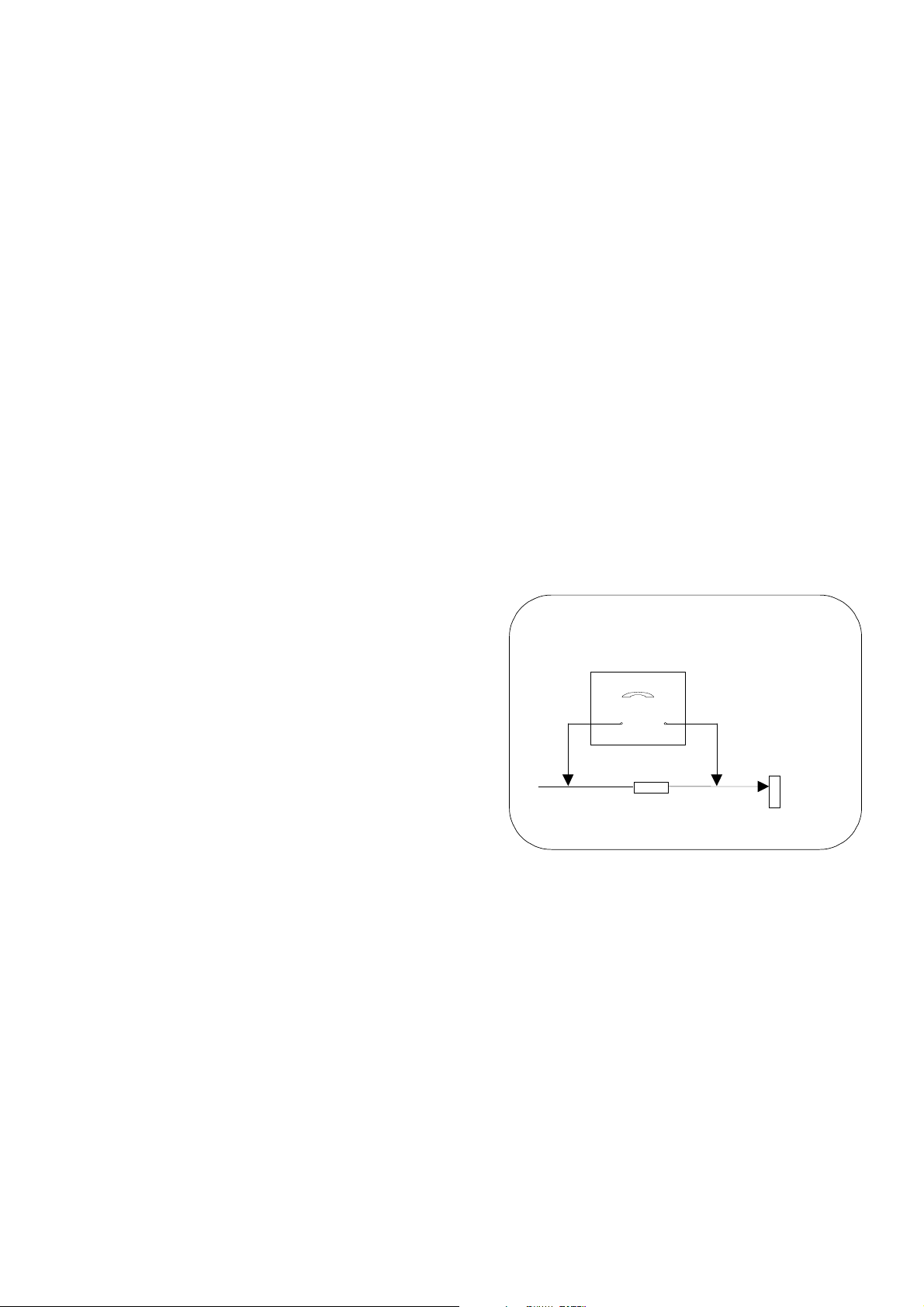
HOT CHECK CIRCUIT
A.C. VOLTMETER
2kΩ 10 Watts
TO INSTRUMENT’S EXPOSED
METALLIC PARTS
Fig. 1.
X-RADIATION WARNING
1. The potential sources of X-Radiation in TV sets are
the high voltage section and the picture tube.
2. When using a picture tube test jig for service, ensure
that the jig is capable of handling 30,5kV without
causing X-Radiation.
NOTE: It is important to use an accurate periodically
calibrated high voltage meter.
1. Set the brightness to minimum.
2. Measure the high voltage. The meter should
indicate :- 30,5kV ± 1kV. If the meter indication is out
of tolerance, immediate service and correction is
required to prevent the possibility of premature
component failure.
3. To prevent any X-Radiation possibility, it is essential
to use the specified tube.
WATER PIPE
(EARTH)
2
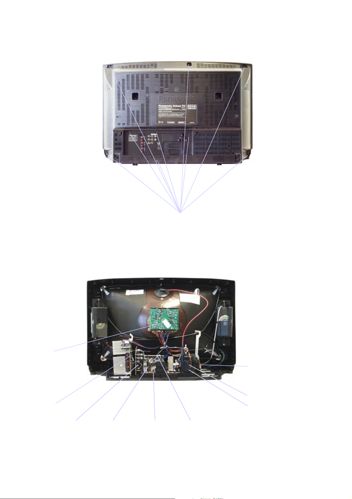
SERVICE HINTS
How to remove the rear cover
1. Remove the 9 screws as shown in Fig.2.
LOCATION OF CONTROLS
Y - Board
SCREWS
Fig.2.
P - Board
C - Board
K - Board
H - Board
Focus
Screen
E - Board M - Board
Fig.3.
3
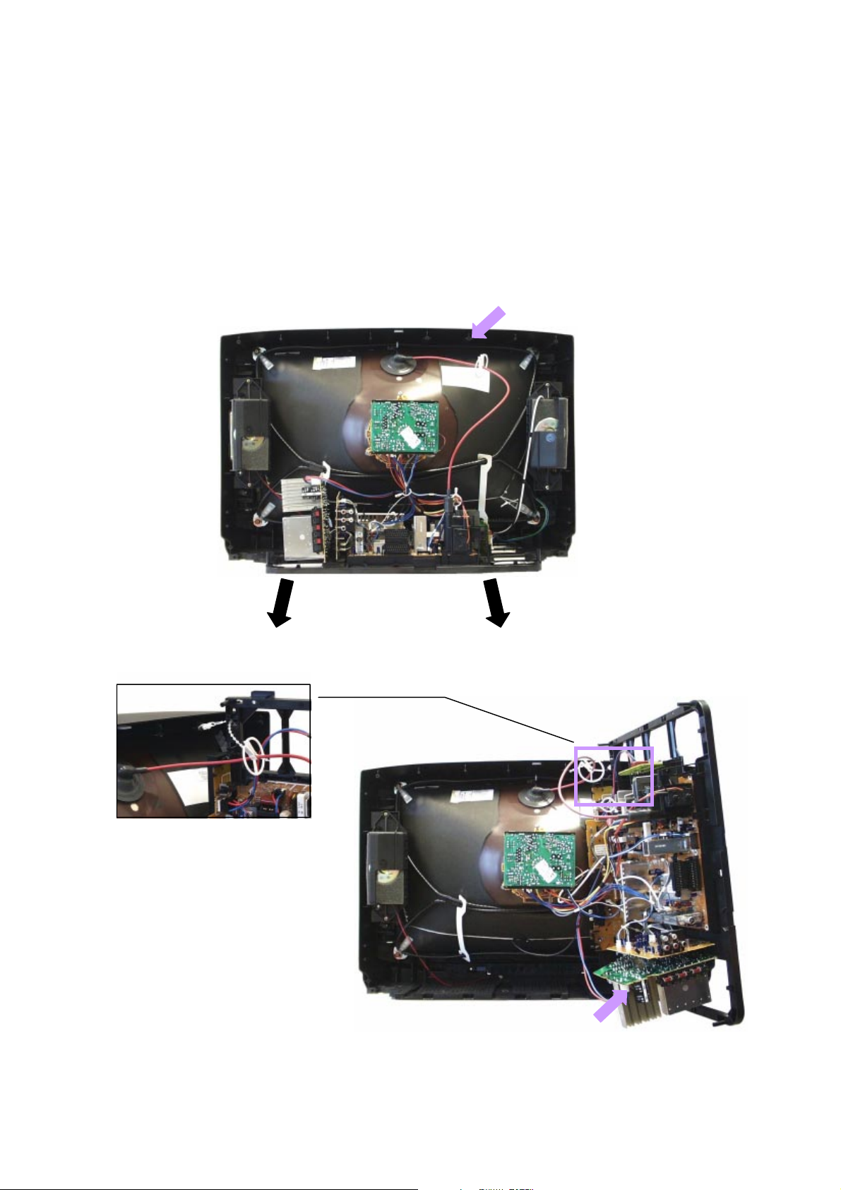
HOW TO MOVE THE CHASSIS INTO SERVICE POSITION
(B)
(A)
1. Remove the bead clamper from the mains lead and affix, using back cover screw, into top right-hand cabinet rib (A),
shown in Fig.4.
2. Hold and lift the rear of the E-PCB chassis and gently pull the chassis toward you, as shown in Fig.4.
3. Release the respective wiring clips and rotate the chassis vertically through 90°, anti-clockwise.
4. Locate the base of the chassis frame into the hole (B), shown in Fig.6.
5. Clip the chassis frame onto the bead clamper, shown in Fig.5.
6. After servicing replace the bead clamper and ensure all wiring is returned to its original position before returning the
receiver to the customer.
Fig.5.
Fig.4.
Fig.6.
4
ADJUSTMENT PROCEDURE
The remote control is used for entering and storing adjustments, with the exception of Cut-off adjustments, which must
always be done prior to service adjustment. Perform adjustments in accordance with screen display. The display on the
screen also specifies the software version as well as the approx. setting values. The adjustment sequence for the service
mode is indicated below.
1. Set the Bass to maximum position, set the Treble to
minimum position, press the F button followed by the
volume down button on the customer controls at the
front of the TV and at the same time press the
"INDEX" button on the remote control, this will place
the TV into the Service Mode.
2. Press the RED / GREEN buttons to step up / down
through the functions.
NOTE: This TV also has the option of using a Memory Pack which enables you to copy the preset TV channels into the
Memory Pack and then download them onto this or any other EURO-4 TV set.
3. Press the YELLOW / BLUE buttons to alter the
function values.
4. Press the STR button after each adjustment has
been made to store the required values.
5. To exit the Service Mode, turn the TV off at the power
button.
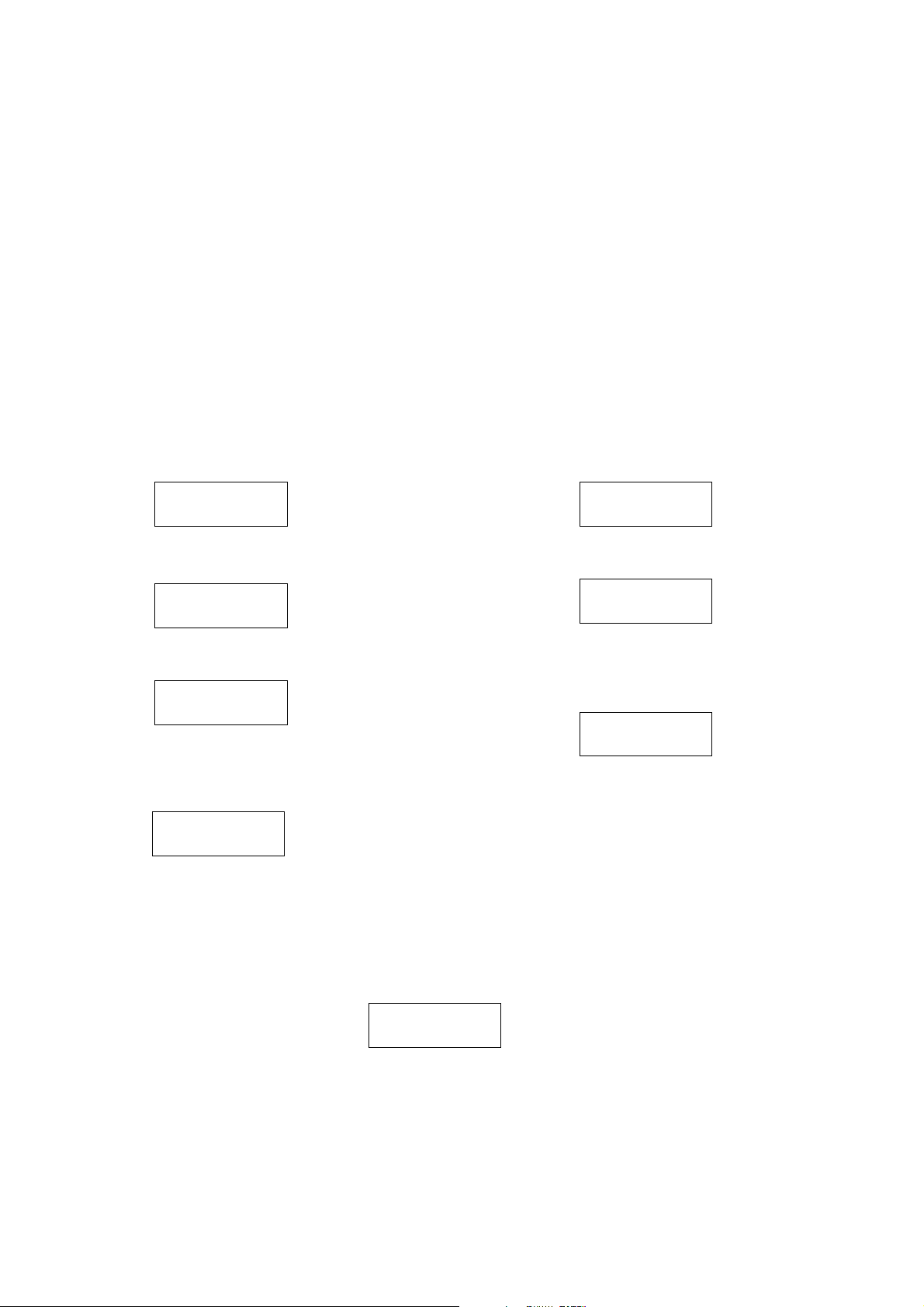
TV to Memory Pack process
1. Plug the memory pack into the AV1 21 pin terminal at
the back of the TV and switch the TV on.
2. Enter Service Mode as explained above.
The screen will show :-
Program
External>>TV
3. Press the BLUE button on the remote control.
The screen will show :-
Program
TV>>External
4. Press the STR button on the TV.
The screen will show :-
Please Wait
5. All the tuning information stored inside the TV will
now be transferred to the Memory Pack. This process
will take 2-3 minutes to complete and when finished
the screen will show :-
Complete
Memory Pack to TV process
1. Plug the memory pack into the AV1 21 pin terminal at
the back of the TV and switch the TV on.
2. Enter Service Mode as explained above.
The screen will show :-
Program
External>>TV
3. Press the STR button on the TV.
The screen will show :-
Please Wait
4. All the tuning information stored inside the Memory
Pack will now be transferred to the TV. This process
will take 2-3 minutes to complete and when finished
the screen will show :-
Complete
5. The tuning information from the Memory Pack has
now been copied into the TV.
6. To exit the Service Mode turn the TV off at the power
button.
7. The process has now been completed and the
Memory Pack can now be removed.
ERRORS
If an error occurs while using the Memory Pack the TV will detect this and the screen will show :-
Error !!
Error !!
If this happens then press the "N" button and repeat the process that was being used. If the errors continue to occur then
check the connectors between the TV and the memory pack and check the 9V battery inside the memory pack.
5
ADJUSTMENT PROCEDURE
Item / Preparation Adjustments
+B SET-UP
1. Receive a Greyscale signal.
2. Set the controls :Brightness Minimum
Contrast Minimum
Volume Minimum
CUT OFF / Ug2 Test
1. Receive a Greyscale signal.
2. Degauss the tube externally.
3. Set the TV into Service Mode 1.
4. Select Cut off mode.
1. Set the +B voltage up as follows:Adjust R811 so that B2 shows 148V±1V.
2. Confirm the following voltages.
B9 5 ± 0,25V B10 5 ± 0,25V
B5 12 ± 0,5V B11 33 ± 1,5V
B4 16 ± 1V B7 8 ± 0,5V
B12 26 ± 1V B8 5,5 ± 0,5V
B3 41 ± 1,5V B13 15 ± 1V
B1 200± 10V B14 -15 ± 1V
To adjust Cutoff connect an oscilloscope to the Blue
cathode, adjust "cutoff" value using the "Yellow" and "Blue"
buttons until the black level is 160V±5V press "STR" to store
the value. Remove the oscilloscope.
Select Ug2 adjustment and adjust the screen VR until the
display shows "O.K."
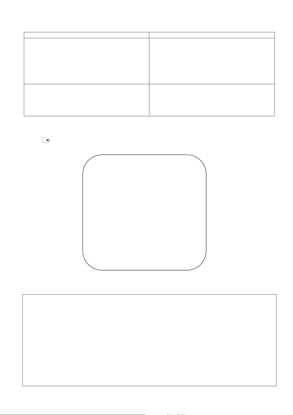
FACTORY SETTINGS
To return customer settings to factory settings and clear owner ID of all information input by the customer, enter Self-Check
mode. Press the down (-/v) button on the customer controls at the front of the TV set, at the same time pressing the STATUS
button on the remote control. To exit Self Check, switch off the TV set at the power button.
NOTE: Self Check should only be used when refurbishing the TV set and not during normal repair work.
VDP O.K.
TUN O.K.
E2 O.K.
PCB O.K.
Cab O.K.
Sum
Factory use only
MSP O.K.
OPTION 1 00
OPTION 2 01
OPTION 3 02
OPTION 4 09
OPTION 5 B1
OPTION 6 A9
Self Check is also used to automatically check the bus lines and hexadecimal code of the TV set. If the CCU ports have
been checked and found to be incorrect or not located then " - - " will appear in place of "O.K.". For more in-depth TV
diagnostics use the LUCI interface as listed below.
Service Aids
To aid in the service of our current chassis there are a number of Service Aids which have been made available.
• LUCI interface kit (Linked Utility Computer Interface)
Part number: TZS6EZ002
This contains interface and cables for connecting TV service connector and a PC as well as diagnostic software. As new
models are introduced upgrade software will become available.
• VICI (Visual Interactive Computer Information)
These C.D.'s contain multimedia documentation providing quick access to service information.
Part No. TZS7EZ006 & TZS7EZ005
1. Service Manuals
2. Instruction Books
3. Technical Information
• TASMIN (Technically Advanced System for Multimedia Interactive Notes)
As well as providing a first step towards more interactive training this product also achieves quick access to Technical
Information.
6
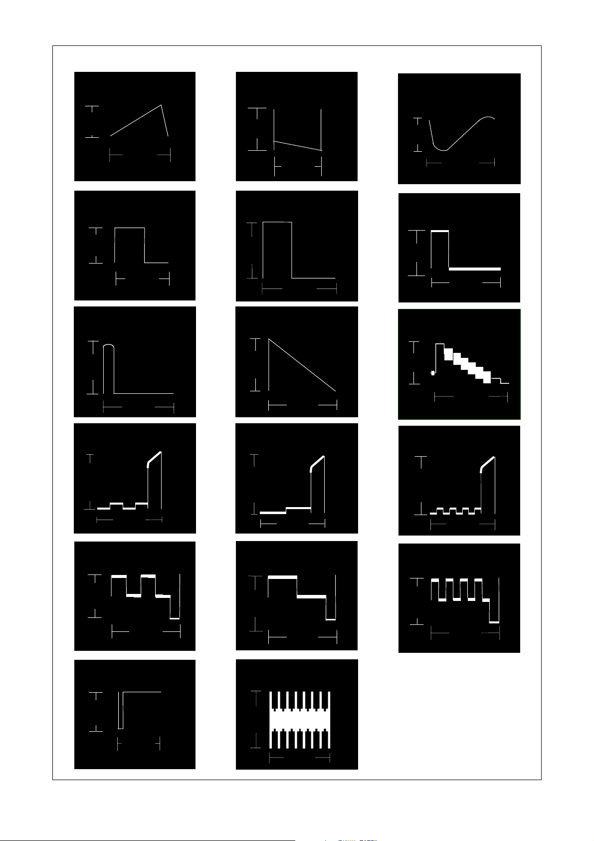
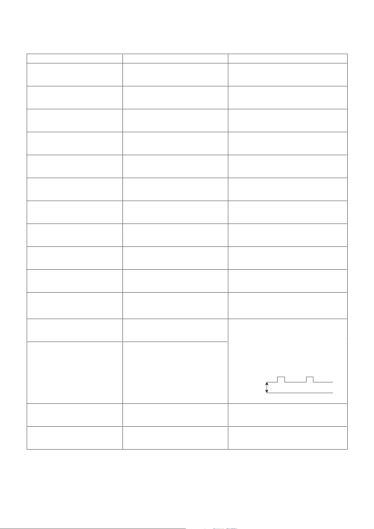
Vert Out
IC601 Pin 31
WAVEFORM PATTERN TABLE
Vert Drive
IC451 Pin 2
VFLB
IC451 Pin 3
0.7V
H - Out
IC601 Pin 50
3V
HFLB
IC601 Pin 13
6.2V
20mS
64µS
64µS
57V
H - Out
IC701 Pin 5
30mV
HFLB
IC701 Pin 8
1.5V
20mS
64µS
64µS
1V
20mS
H - Pulse
Base Q503
2V
64µS
Video Out
IC601 Pin 59
2V
64µS
R - Out
IC601 Pin 37
275mV
R - Out
E8 Pin 5
4.6V
SCL
IC1201 Pin 3
3.7V
64µS
64µS
G - Out
IC601 Pin 38
275mV
G - Out
E8 Pin 3
4.4V
SVM Out
IC601 Pin 34
88mV
64µS
64µS
B - Out
IC601 Pin 39
275mV
64µS
B - Out
E8 Pin 4
4.6V
64µS
13µS
64µS
7
ALIGNMENT SETTINGS
(The figures below are nominal and used for representative purposes only.)
Alignment Function Settings / Special features
Horizontal Position
Vertical Position
Horizontal Amplitude
Vert. Amplitude
EW-amplitude
EW-amplitude
Trapezium-comp
Trapezium-comp
H-Pos
061
V-Pos
005
H-Amp
055
V-Amp
054
E/W-Amp1
-128
E/W-Amp2
006
Trapez-1
047
Trapez-2
-128
Optimum setting.
Optimum setting.
Optimum setting.
Optimum setting.
Optimum setting.
Optimum setting.
Optimum setting.
Optimum setting.
Vertical Linearity
Vertical Symmetry
DVCO
Cut-off DC
Ug2 Test
Highlight
Lowlight
Sub-Brightness
V-Lin
006
V-Sym
002
DVCO
-005
Cut-off
0171
Ug2
055
O.K.
High 0902 0777 0864
Low 0117 0132 0112
Sub-Brightness
255
Optimum setting.
Optimum setting.
Receive a PAL Colour Bar Pattern. For
DVCO alignment press "Blue" button, wait
until the colours are changing slowly and
press "STR".
To adjust Cutoff connect an oscilloscope to
the blue cathode, adjust "cutoff" value
using the "Yellow" and "Blue" buttons until
the black level is 160V±5V press "STR" to
store the value. Remove the oscilloscope.
Select Ug2 adjustment and adjust the
screen VR until the display shows "O.K."
Black Level
160V±5V
GND
Optimum setting.
Optimum setting.
8
,Q
Q352Q35
,Q
&
Q35
9
Y
C
AV1
9LGHR2XW
%OXH
*UHHQ
5HG
9LGHR
AV2
9LGHR
$9
2XW
9LGHR
E - BOARD
Q105
Q3001
Q104
61 V IN 1
43 B IN
42 G IN
41 R IN
62 VIN 2
63 VIN 3
60 C IN
VIN 4
64
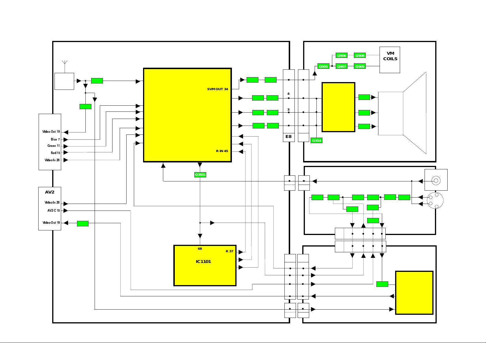
VIDEO BLOCK DIAGRAM
IC601
VIDEO
PROCESSOR
VIDEO OUT
59
Q3601
SVM OUT 34
B OUT 39
G OUT 38
R OUT 37
B IN 47
G IN 46
R IN 45
Q950 Q951
Q303
Q304
Q301
Q302
7
7
4
4
3
3
5
5
E8
Y2
66
M2
E17
Y - BOARD
Q905 Q907 Q909
IC351
3
RGB
OUTPUT
2
1
4
M - BOARD
7
8
9
Q3207
Q908Q906
Q353
VM
COILS
CRT
1
AV3
Q3204
Q3205Q3206Q3208Q3209
Q3202
Q3201
Q3203
68
CVBS
IC1101
MICRO
PROCESSOR
R 37
G 38
B 39
M3
H2
H - BOARD
E158H1
2 2
4 4
6 6
8
1 1
2 6
6
4
82
4 8
IC3401
Q3402
8
VIDEO
SWITCHING
6
3
H3E61
E - BOARD
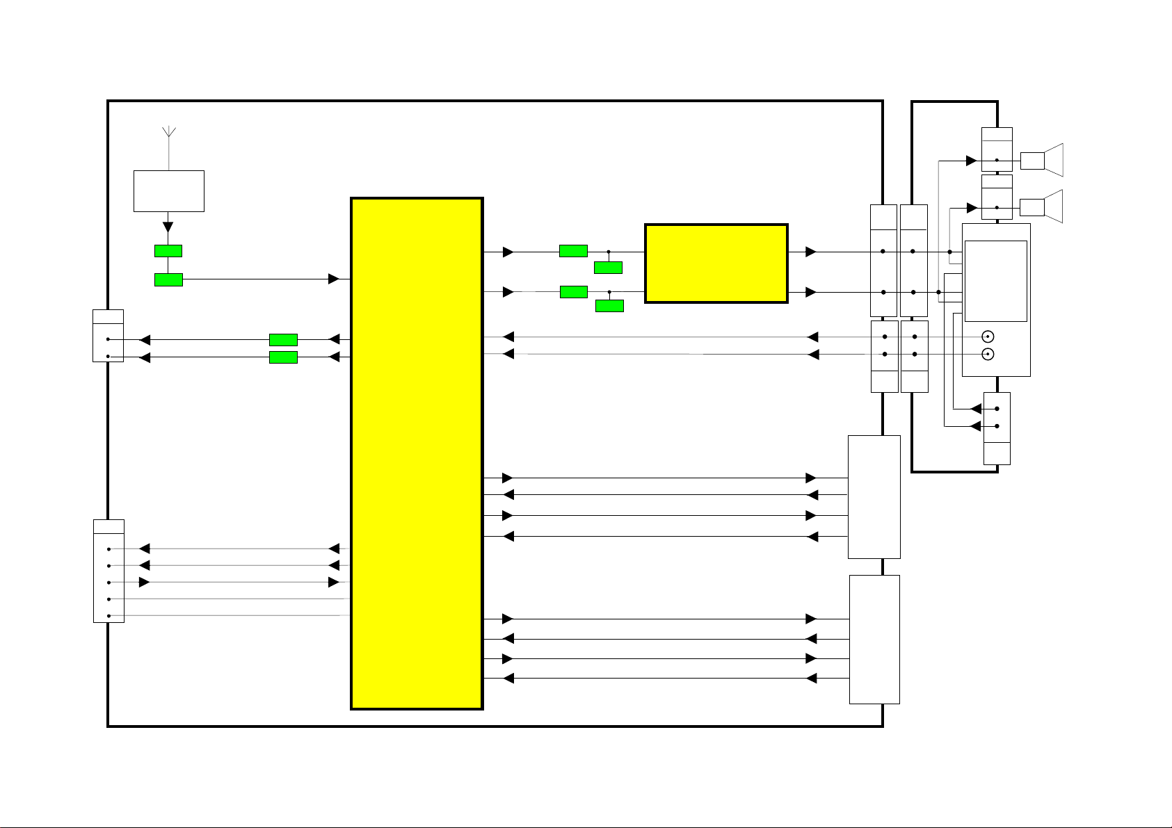
AUDIO BLOCK DIAGRAM
M - BOARD
M4
1
K7
DACA_R
DACA_L
10
K3
I2S_DA_IN_2
I2S_DA_IN_1
I2S_DA_OUT
I2S_DA_WS
I2S_DA_CL
E22
3
1
E12
TUNER
Q101
Q102
Q2304
Q2302
IC2101
AUDIO
PROCESSOR
47 ANA_IN1+
21 DACA_R
22 DACA_L
DACM_R 24
DACM_L 25
SC3_IN_L 37
SC3_IN_R 38
Q2102
Q2103
Q252
Q251
5 R
2 L
IC251
AUDIO
OUTPUT
R 7
L 11
E16A M1
1 1
2 2
10 10
8 8
M5
3
AV3
6 R
7 R
3 R
HEADPHONE
5 L
4 L
2 L
L
R
E17 M2
1
3
M6 K8
SC1_OUT_R 30
SC1_IN_R 42
SC1_OUT_L 31
3
4
5
6
7
18 I2S_DA_IN_2
12 I2S_DA_IN_1
11 I2S_DA_OUT
10 I2S_DA_WS
9 I2S_DA_CL
SC1_IN_L 41
SC2_OUT_R 27
SC2_IN_R 40
SC2_OUT_L 28
SC2_IN_L 39
1 R OUT
2 R IN
3 L OUT
6 L IN
AV1
1 R OUT
2 R IN
3 L OUT
6 L IN
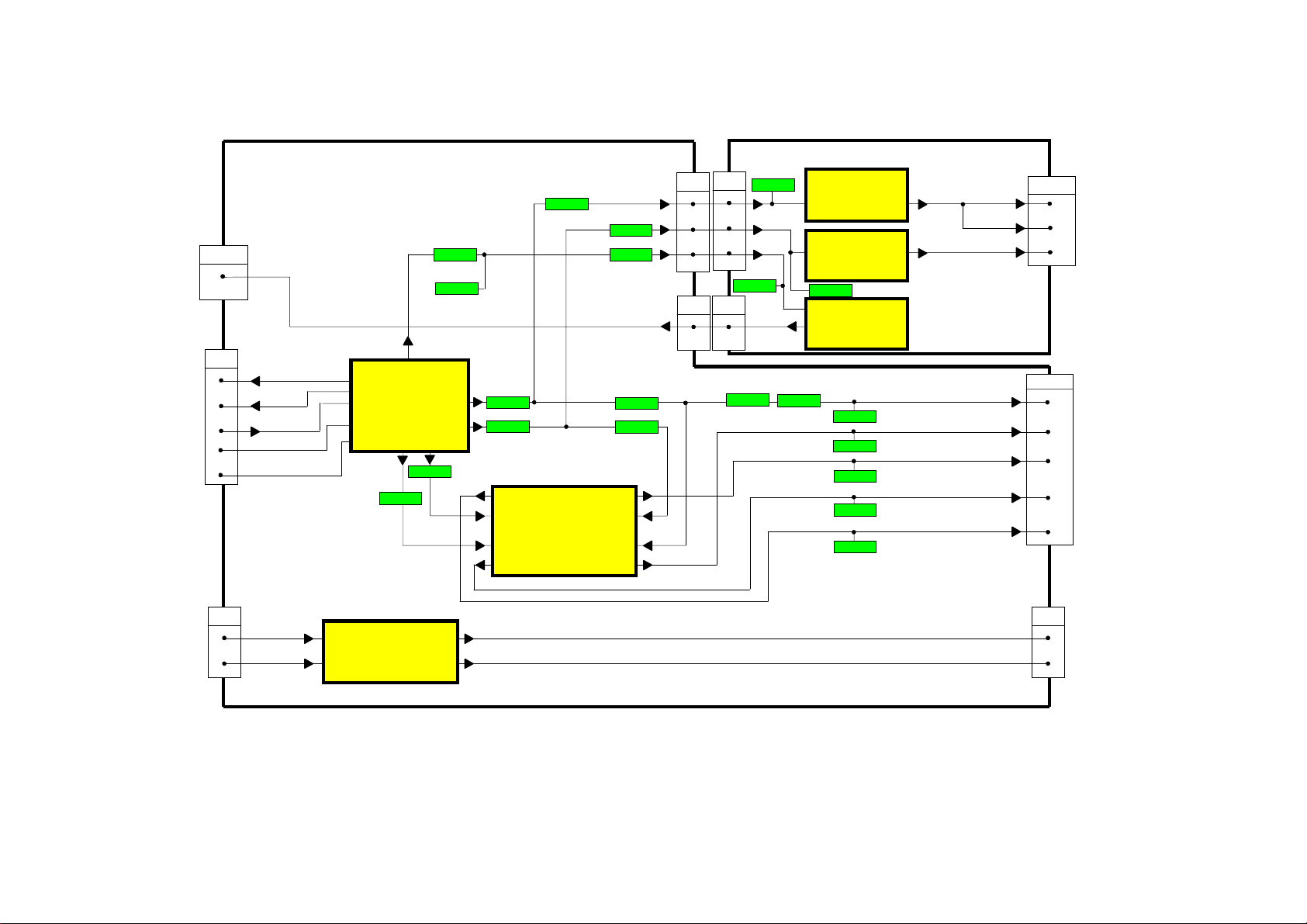
DOLBY BLOCK DIAGRAM
11
Woofer
E12 K3
I2S_DA_OUT_2
I2S_DA_OUT_1
I2S_DA_IN
I2S_WS
I2S_CL
JK2402
3
4
5
6
7
K - BOARD
27
19
IC2401
11
12
DOLBY
PROCESSOR
10
9
21
Q2409
Q2410
Q2423
Centre
Woofer
Q2426 Q2428
Q2427
Q2403
24
25
Q2401
22
1
3
5
7
IC2402
OPERATIONAL
AMPLIFIER
Surround
Q2425
Q2404
Q2402
14
12
10
8
K5
K6
C - BOARD
C2
Q2705
1
1
3
3
5
5
Q2703
C5
1
1
IC2704
AUDIO
1
AMPLIFIER
IC2703
1
AUDIO
AMPLIFIER
Q2704
IC2702
1
AUDIO
4
AMPLIFIER
JK2702
4
4
Surround L
Surround R
Centre
JK2401
Q2405
Q2406
Q2419
Surround R
Surround L
Q2418
Centre Out
Q2417
Right Front
Q2421
Left Front
Q2420
E22 K7
Audio Left
Audio Right
K8 M6
1
3
HEADPHONE
AMPLIFIER
5
IC2404
13
7
Headphone Left
1
Headphone Right
3
 Loading...