

Panasonic TX-S User Manual
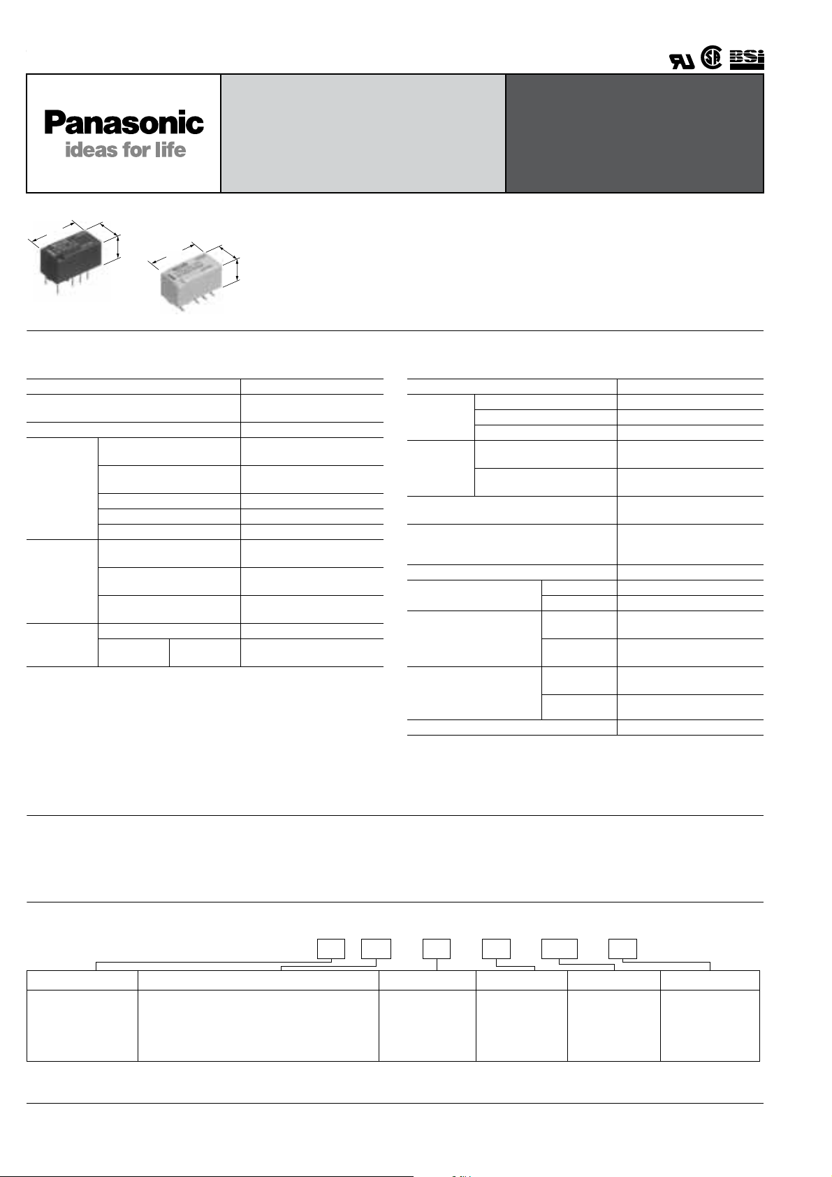
TX-S
SMALL POLARIZED
RELAY WITH HIGH
SENSITIVITY 50mW
15
.591
mm inch
7.4
.291
8.2
.323
15
.591
7.4
.291
SA type
SPECIFICATIONS
Contact
Arrangement 2 Form C
Initial contact resistance, max.
(By voltage drop 6 V DC 1 A )
Contact material Gold-clad silver alloy
Nominal switching capacity
(resistive load)
Max. switching power
Rating
Nominal
operating
power
Expected
life (min.
operations)
Note:
❇1 This value can change due to the switching frequency , environmental conditions ,
and desired reliability level, therefore it is recommended to check this with the
actual load. (SX relays are a vailab le for lo w lev el load s witching [10 µA 1 mV DC
– 10 mA 10 V DC])
Remarks
* Speci cations will vary with foreign standards certi cation ratings.
1
Measurement at same location as “Initial breakdown voltage” section.
*
2
Detection current: 10mA
*
3
Excluding contact bounce time.
*
4
By resistive method; nominal v oltage applied to the coil; contact carrying current:
*
1 A.
(resistive load)
Max. switching voltage 110 V DC
Max. switching current 1 A
Min. switching capacity ❇1 10 µA 10 mV DC
Single side stable
1 coil latching
2 coil latching
Mechanical (at 180 cpm) 5×10
Electrical
(at 20 cpm)
1 A 30 V DC
resistive
FEATURES
High sensitivity
• 50mW nominal operating power
8.4
(single side stable 1.5-12V)
.331
• Useful for electric-power-saving
Approx. 0.3µV low thermal
electromotive force
100 mΩ
1 A 30 V DC
30 W (DC)
50 mW (1.5 to 12 V DC)
70 mW (24 V DC)
35 mW (1.5 to 12 V DC)
50 mW (24 V DC)
70 mW (1.5 to 12 V DC)
150 mW (24 V DC)
2×10
7
5
TX-S
RELAYS
Outstanding surge resistance
Surge withstand between open contacts:
1,500V 10×160µs (FCC part 68)
Surge withstand between contacts and
coil:
2,500V 2×10µs (Telcordia)
Characteristics
Initial insulation resistance*
Initial
breakdown
voltage*
Initial surge
voltage
Operate time [Set time]*
(at 20°C)(at nominal voltage)
Release time (without diode)
[Reset time]*
(at 20°C)(at nominal voltage)
Temperature rise*4 (at 20°C) Max. 50°C
Shock resistance
Vibration resistance
Conditions for operation,
transport and storage*
(Not freezing and condensing
at low temperature)
Unit weight Approx. 2 g .071 oz
5
Half-wave pulse of sine wave: 6 ms; detection time: 10 µs
*
6
Half-wave pulse of sine wave: 6 ms
*
7
Detection time: 10 µs
*
8
Refer to 6. Conditions for operation, transport and storage mentioned in
*
AMBIENT ENVIRONMENT
Between open contacts 750 Vrms for 1min.
Between contact sets 1,000 Vrms for 1min.
2
Between contacts and coil 1,800 Vrms for 1min.
Between open contacts
(10 × 160µs)
Between contacts and coil
(2 × 10 µs)
3
1
3
Functional*
Destructive*6Min. 1,000 m/s2 {100 G}
Functional*
Destructive
Ambient
8
temperature
Humidity 5 to 85% R.H.
Min. 1,000 MW (at 500 V DC)
1,500V (FCC Part 68)
2,500V (Telcordia)
Max. 5 ms (Approx. 3 ms)
[Max. 5 ms (Approx. 3 ms)]
Max. 5 ms (Appro x. 1.5 ms)
[Max. 5 ms (Approx. 3 ms)]
5
Min. 750 m/s2 {75 G}
10 to 55 Hz at double
7
amplitude of 3.3 mm
10 to 55 Hz at double
amplitude of 5 mm
–40°C to +70°C
–40°F to +158°F
TESTING
TYPICAL APPLICATIONS
• Communications
(XDSL, Transmission)
• Measurement
• Security
• Home appliances, and audio/visual
equipment
•Automotive equipment
• Medical equipment
ORDERING INFORMATION
2SA L 3VHZEx. TXS
Contact arrangement Surface-mount availability Operating function Coil voltage (DC)
2: 2 Form C Nil: Single side
Notes: 1. Tape and reel (picked from 1/3/4/5-pin side) is also available by request. Part number suffix “-X” is needed when ordering.
(ex.) TXS2SA-3 V-X
2. Tape and reel packing symbol “-Z” or “-X” are not marked on the relay.
Nil: Standard PC board terminal type or
Nil: self-clinching terminal type
SA: Standard surface-mount terminal type
SL: High connection reliability surface-mount
SL: terminal type
SS: Space saving surface-mount terminal type
All Rights Reserved © COPYRIGHT Matsushita Electric Works, Ltd.
––– –
Terminal shape
Nil: stable
L: 1 coil latching
L2: 2 coil latching
Nil: Standard PC
board terminal or
surface-mount
terminal
H: Self-clinching
terminal
1.5, 3, 4.5, 6, 9,
12, 24 V
Packing style
Nil: Tube packing
Z: Tape and reel
packing(piked
from the 8/9/10/12
-pin side
Ω ( ±
Ω ( ±
Ω ( ±
Ω ( ±
TX-S
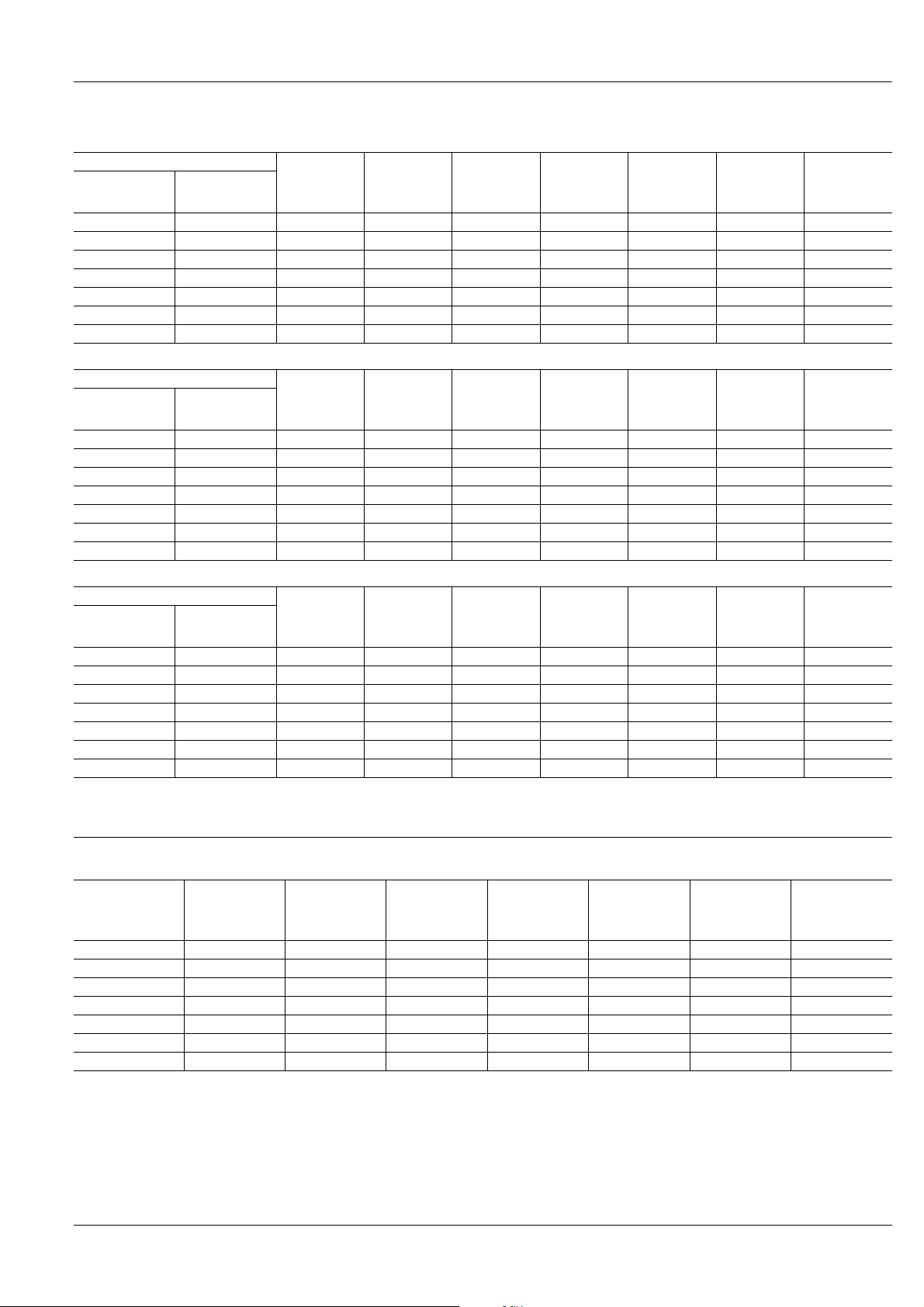
TYPES AND COIL DATA (at 20 ° C 68 ° F)
1) Standard PC board terminal type and self-clinching terminal type
Single side stable
Part No.
Standard PC
board terminal
TXS2-1.5V TXS2-H-1.5V 1.5 1.2 0.15 33.3 45 50 2.2
TXS2-3V TXS2-H-3V 3 2.4 0.3 16.7 180 50 4.5
TXS2-4.5V TXS2-H-4.5V 4.5 3.6 0.45 11.1 405 50 6.7
TXS2-6V TXS2-H-6V 6 4.8 0.6 8.3 720 50 9
TXS2-9V TXS2-H-9V 9 7.2 0.9 5.6 1,620 50 13.5
TXS2-12V TXS2-H-12V 12 9.6 1.2 4.2 2,880 50 18
TXS2-24V TXS2-H-24V 24 19.2 2.4 2.9 8,229 70 36
Self-clinching
terminal
Nominal
voltage, V DC
Pick-up
voltage,
V DC (max.)
Drop-out
voltage,
V DC (min.)
1 coil latching
Part No.
Standard PC
board terminal
TXS2-L-1.5V TXS2-L-H-1.5V 1.5 1.2 1.2 23.3 64.3 35 2.2
TXS2-L-3V TXS2-L-H-3V 3 2.4 2.4 11.7 257 35 4.5
TXS2-L-4.5V TXS2-L-H-4.5V 4.5 3.6 3.6 7.8 579 35 6.7
TXS2-L-6V TXS2-L-H-6V 6 4.8 4.8 5.8 1,029 35 9
TXS2-L-9V TXS2-L-H-9V 9 7.2 7.2 3.9 2,314 35 13.5
TXS2-L-12V TXS2-L-H-12V 12 9.6 9.6 2.9 4,114 35 18
TXS2-L-24V TXS2-L-H-24V 24 19.2 19.2 2.1 11,520 50 36
Self-clinching
terminal
Nominal
voltage,
V DC
Set voltage,
V DC (max.)
Reset voltage,
V DC (Max.)
2 coil latching
Part No.
Standard PC
board terminal
TXS2-L2-1.5V TXS2-L2-H-1.5V 1.5 1.2 1.2 46.7 32.1 70 2.2
TXS2-L2-3V TXS2-L2-H-3V 3 2.4 2.4 23.3 129 70 4.5
TXS2-L2-4.5V TXS2-L2-H-4.5V 4.5 3.6 3.6 15.6 289 70 6.7
TXS2-L2-6V TXS2-L2-H-6V 6 4.8 4.8 11.7 514 70 9
TXS2-L2-9V TXS2-L2-H-9V 9 7.2 7.2 7.8 1,157 70 13.5
TXS2-L2-12V TXS2-L2-H-12V 12 9.6 9.6 5.8 2,057 70 18
TXS2-L2-24V TXS2-L2-H-24V 24 19.2 19.2 6.3 3,840 150 36
Notes:
1. Speci ed value of pick-up, drop-out, set and reset voltage is with the condition of square wave coil pulse.
2. Standard packing: Tube: 40 pcs.; Case: 1,000 pcs.
Self-clinching
terminal
Nominal
voltage,
V DC
Set voltage,
V DC (max.)
Reset voltage,
V DC (Max.)
Nominal
operating
current,
mA ( ± 10%)
Nominal
operating
current,
mA ( ± 10%)
Nominal
operating
current,
mA ( ± 10%)
Coil
resistance,
10%)
Coil
resistance,
10%)
Coil
resistance,
10%)
Nominal
operating
power,
mW
Nominal
operating
power,
mW
Nominal
operating
power,
mW
Max.
Allowable
voltage,
V DC
Max.
Allowable
voltage,
V DC
Max.
Allowable
voltage,
V DC
2) Surface-mount terminal type
Single side stable
Part No.
TXS2S ❍ -1.5 V 1.5 1.2 0.15 33.3 45 50 2.2
TXS2S ❍ -3 V 3 2.4 0.3 16.7 180 50 4.5
TXS2S ❍ -4.5 V 4.5 3.6 0.45 11.1 405 50 6.7
TXS2S ❍ -6 V 6 4.8 0.6 8.3 720 50 9
TXS2S ❍ -9 V 9 7.2 0.9 5.6 1,620 50 13.5
TXS2S ❍ -12 V 12 9.6 1.2 4.2 2,880 50 18
TXS2S ❍ -24 V 24 19.2 2.4 2.9 8,229 70 36
Nominal
voltage,
V DC
Pick-up voltage,
V DC (max.)
All Rights Reserved © COPYRIGHT Matsushita Electric Works, Ltd.
Drop-out
voltage,
V DC (min.)
Nominal
operating
current,
mA ( ± 10%)
Coil resistance,
10%)
Nominal
operating power ,
mW
Max. Allowable
voltage,
V DC
❍
Ω ( ±
Ω ( ±
TX-S
1 coil latching
Nominal
operating
current,
mA ( ± 10%)
Nominal
operating
current,
mA ( ± 10%)
Coil resistance,
10%)
Coil resistance,
10%)
Nominal
operating power ,
mW
Nominal
operating power ,
mW
Max. Allowable
voltage,
V DC
Max.
Allowable
voltage,
V DC
Part No.
Nominal
voltage,
V DC
Set voltage,
V DC (max.)
Reset voltage,
V DC (max.)
TXS2S ❍ -L-1.5 V 1.5 1.2 1.2 23.3 64.3 35 2.2
TXS2S ❍ -L-3 V 3 2.4 2.4 11.7 257 35 4.5
TXS2S ❍ -L-4.5 V 4.5 3.6 3.6 7.8 579 35 6.7
TXS2S ❍ -L-6 V 6 4.8 4.8 5.8 1,029 35 9
TXS2S ❍ -L-9 V 9 7.2 7.2 3.9 2,314 35 13.5
TXS2S ❍ -L-12 V 12 9.6 9.6 2.9 4,114 35 18
TXS2S ❍ -L-24 V 24 19.2 19.2 2.1 11,520 50 36
2 coil latching
Part No.
voltage,
V DC
TXS2S ❍ -L2-1.5 V 1.5 1.2 1.2 46.7 32.1 70 2.2
TXS2S ❍ -L2-3 V 3 2.4 2.4 23.3 129 70 4.5
TXS2S ❍ -L2-4.5 V 4.5 3.6 3.6 15.6 289 70 6.7
TXS2S ❍ -L2-6 V 6 4.8 4.8 11.7 514 70 9
TXS2S ❍ -L2-9 V 9 7.2 7.2 7.8 1,157 70 13.5
TXS2S ❍ -L2-12 V 12 9.6 9.6 5.8 2,057 70 18
TXS2S ❍ -L2-24 V 24 19.2 19.2 6.3 3,840 150 36
Nominal
:For each surface-mounted terminal variation, input the following letter.
SA type: A, SL type: L, SS type: S
Notes:
1.Speci ed v alue of pick-up, drop-out, set and reset voltage is with the condition of square wave coil pulse.
2.Standard packing: Tube: 40 pcs. ; Case: 1,000 pcs.
3.Tape and reel packing is also available for surface-mount type by request. Part number suf x "-X" or "-Z" is needed when orde ring.
In this case, "X" or "Z" are not marked on the relay.
Quantity in tape and reel: 500 pcs.
(ex.) • TXS2SA-3V-X
• TXS2SA-L-3V-Z
Picked from the 1/3/4/5-pin side Picked from the 8/9/10/12-pin side
Set voltage,
V DC (max.)
Reset voltage,
V DC (max.)
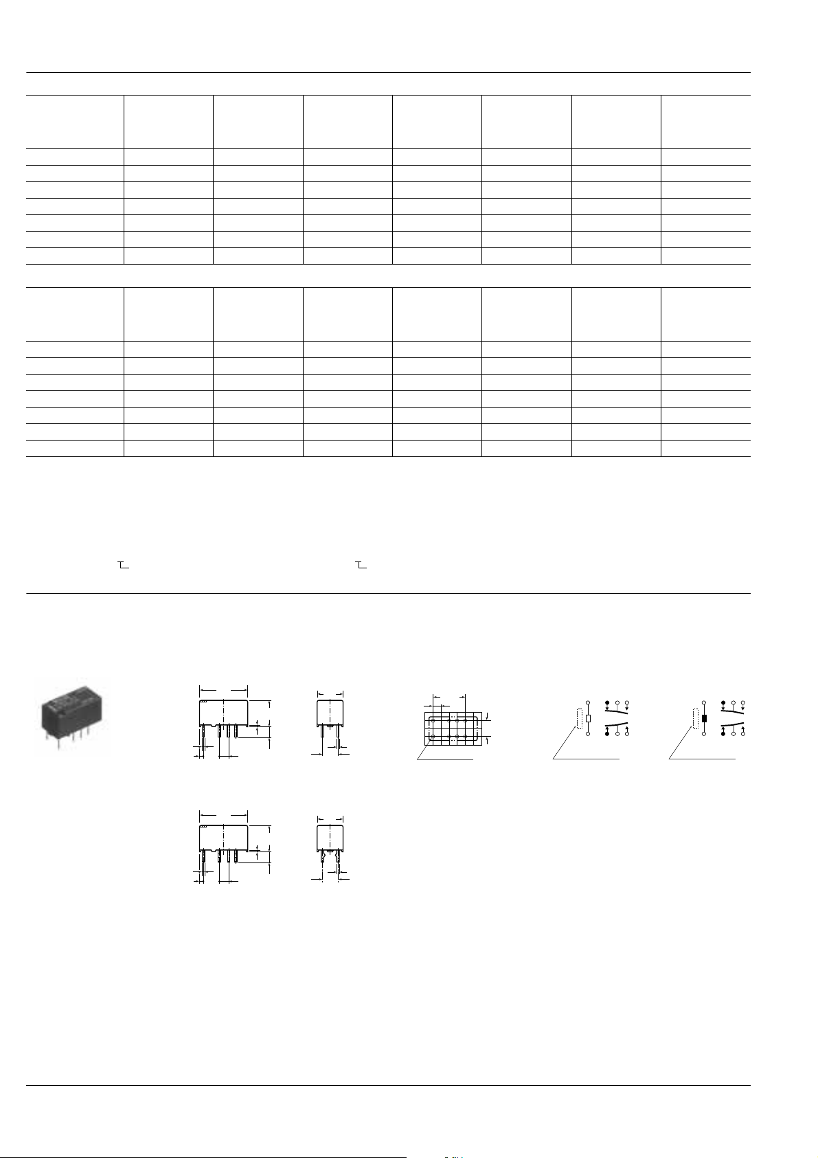
DIMENSIONS
1. Single side stable and 1 coil latching type
Standard PC board terminal
15
.591
0.65
8.2
.026
.323
3.5
2.54
.100
2.54
.100
0.65
.026
8.2
.323
.138
3.5
.138
Self clinching terminal
0.5
.020
1.15
5.08
.045
.200
15
.591
0.5
.020
1.15
5.08
.045
.200
General tolerance: ±0.3 ±.012
.291
.291
7.4
5.08
.200
7.4
5.08
.200
0.25
.010
0.25
.010
PC board pattern
(Copper-side view)
10.16
.400
2.54
.100
5.08
.200
8-1.0 dia
8-.039 dia
Tolerance: ±0.1 ±.004
Schematic (Bottom view)
Single side stable
(Deenergized condition)
1 3 4 5
+
–
12 10 9 8
Direction indication*
*Orientation stripe located on top of relay.
mm inch
1 coil latching
(Reset condition)
1 3 4 5
–
+
12 10 9 8
Direction indication*
All Rights Reserved © COPYRIGHT Matsushita Electric Works, Ltd.
 Loading...