

Panasonic TX-47WG25 User Manual
1 Operating Instructions
Wide Video Projection System
TX-47WG25 series
This is a combined Operating
Instruction manual for all the
above series of models.
Please read these instructions
before operating your Wide Video
Projection System and retain
them for future reference.
TQBC0022

Dear Panasonic Customer
Welcome to the Panasonic family of Customers. We hope that you will
have many years of enjoyment from your new Wide Video Projection System.
To obtain maximum benefit from your set, please read these Instructions
before making any adjustments, and retain them for future reference.
Retain your purchase receipt also, and note down the Model Number and
Serial Number of your set in the space provided on the rear cover of these
Instructions.
— AR/AS Coating on the Screen ---------------------------------------------------
The Screen is coated with a special material to hinder ambient light
reflection and dust adherence. It aids picture performance during high
ambient light conditions. The AR/AS coating may be observed when
the set is switched off, since the coating give the screen surface a faint
purplish or blue hue. Take care not to mark or scratch this coating.
{TX-47WG25X are not equipped.)
Note:
(1) The long time (max. 2 hours) use of TV game on the set is not recommended since the
signal from TV game may be the cause of damage on picture projection tubes on the set.
(2) Do not allow any still picture or parts of picture that do not move on the screen for an ex
tended length of time. These pictures can adversely affect your picture projection tubes.
Some examples of still images are Television programming logos, Video games, Computers
and Text programmes, etc. If still picture cannot be avoided, reduce the brightness and
contrast levels of the picture to minimize any damage that might occur.
Table of Contents
Warnings and Cautions
Before Operating This Set
Connect the Aerial Cable to the RF in Terminal
Connect the Plug to the wall outlet
How to Turn the Power On
Battery Installation................................................
...................................
.....................
Channel Selection.......................................
Country System Selection.........................
Automatic Tune
Manual Tune
Fine Tuning.................................................
How to Cancel the Fine Tuning Function
Programme Number Skip
How to Cancel the Skip Function
..........................................
...............................................
..........................
.............
.
.
General Operation
How to switch the power ON or OFF/Stand-By Mode
Programme Number Selection
Direct Programme Number Selection
TV/AV Mode Selection
Volume Adjustment
Display Button................................................................
Mute Button
Recall Button..................................................................
Off Timer Button.............................................................
Sound System Selection
Colour System Selection...............................................
....................................................................
...................................................
.......................................................
.....................................
..........................
...............................................
Advanced Remote Control Operation
Manual ASPECT Operation..................................................................
Multi Window Operation.......................................................................
SELF ASPECT Operation
STROBE Operation...............................................................................
Picture in Picture Operation
Stereo Reception (The TX-47WG25C does not have this function.)
Surround Operation..............................................................................
Picture Menu Operation.....................
Sound Menu Operation.........................................................................
Main Menu Operation............................................................................
Main Menu Operation (Aspect, Picture, Sound).................................
Features Menu Operation (BLUE BACK, RF/AV, P*DE).....................
Features Menu Operation (SELF ASPECT, SIDE BAND)...................
.....................................................................
................................................................
..................................................
.18
.20
.22
.24
.26
.27
.28
.29
.30
.30
.30
.30
.31
.31
.31
.31
.31
.32
.33
.34
.36
.38
.39
.40
.42
.44
.45
.46
.48
.49
.50
.51
Teletext Operation
52
Operation of the VCR 56
Troubleshooting
Specifications
57
58
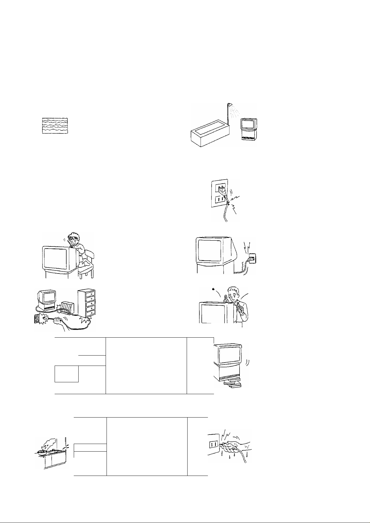
Warnings and Cautions
/4\ Warnings
Unplug the power cord in
the event of any
malfunction (screen goes
blank, no sound, odd
sounds, smoke or unusual
odors coming from the
/oj
IQ
J
set).
Unplug the power cord if
foreign matter or water
falls into the set, or if the
set is dropped or the
cabinet is damaged.
DO NOT place any of the
following on the set:
Flower vases, flower pots,
cups, small metal objects,
or cosmetics containers,
chemicals or water.
DO NOT insert foreign
objects (metal or easily
flammable objects).
DO NOT use this set near
water, (near a bath tub,
etc.)
DO NOT use if the power
cord or power plug is
damaged, or if the plug
does not fit tightly into the
socket.
DO NOT use at a voltage
other than indicated.
1-—r
A, Cautions
□'1
^ ff
1
M
:0:
\ ' /
TAKE CARE NOT to
damage the power cord.
DO NOT touch the aerial
cable and this set when
there is lightning.
DO NOT place in humid or
dusty locations, or areas
exposed to smoke or
steam.
Do NOT place the direct
sunlight and other sources
of direct heat.
DO NOT remove the rear
cover as live parts and
High Voltage components
are accessible when the
rear cover is removed.
T=P
DO NOT place in an
unstable location.
1
DO NOT touch the power
plug if your hands are wet.
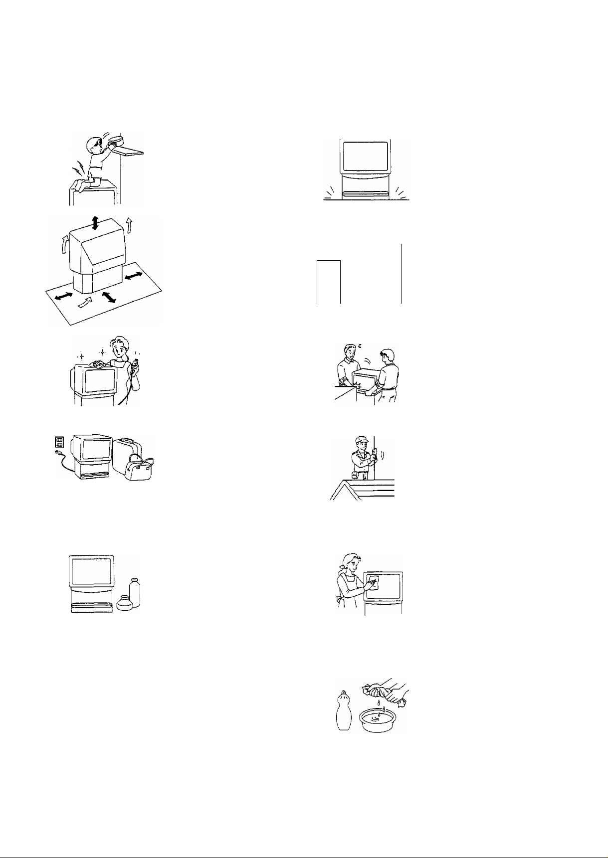
Warnings and Cautions
Ж Cautions
DO NOT stand, or place
heavy objects on the set.
Particular care should be
taken by families with
small children.
Adequate ventilation is
essential to prevent failure
of electrical components,
we recommend that a gap
of at least 10cm (◄i-^) is
left all around this set even
when it is placed inside a
cabinet or between
shelves.
Before cleaning, unplug
the power plug from the
socket.
Unplug the power plug
from the socket if you are
not going to use the set for
an extended period.
_____
(Щ )
Place in a safe location.
Turn the power “Off
before connecting other
^
.riJ
electrical equipment.
DO NOT jolt the set.
Ask your sales outlet to
install the aerial.
Cleaning
The set contains many
plastic parts. For this
reason DO NOT use
benzine, thinner or other
chemicals to clean the set.
DO NOT bring into contact
with insecticide or other
volatile substances.
DO NOT allow the set to
come into contact for
extended periods with
rubber or vinyl products.
Dust will accumulate on
the picture screen. Please
wipe with a soft cloth from
time to time. If you use a
chemically treated cloth,
please be careful to follow
the instructions that come
with the cloth.
Remove dirt and soiling by
wiping with a soft cloth.
Even if the set is heavily
soiled, do not apply
cleaner directly to the set.
Soak a soft cloth in a
solution of neutral cleanser
thinned with water. Then
wring out the cloth, wipe
the set clean, and finish by
wiping with a dry soft cloth.
Before Operating This Set
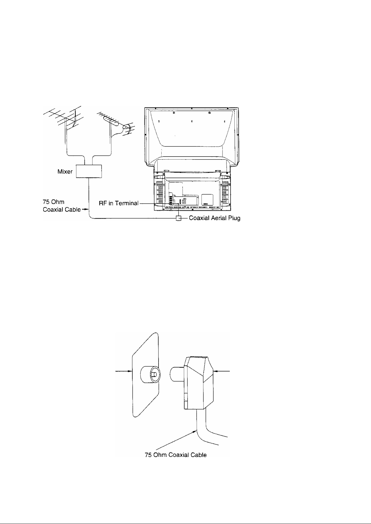
Connect the Aerial Cable to the RF in Terminal
VHF Aerial
To obtain optimum quality picture and sound, an Aerial, the correct cable (75 Ohm coaxial) and the correct
terminating plug are required.
if a communal Aerial system is used, you may require the correct connection cable and plug between the wall Aerial
socket and your set.
Your local Television Service Centre or Dealer may be able to assist you in obtaining the correct Aerial system for
your particular area and accessories required.
UHF Aerial
Any matters regarding Aerial installation, upgrading of existing systems or accessories required, and the costs
incurred, are the responsibility of you, the Customer.
RF in Terminal Coaxial aerial plug
Before Operating This Set
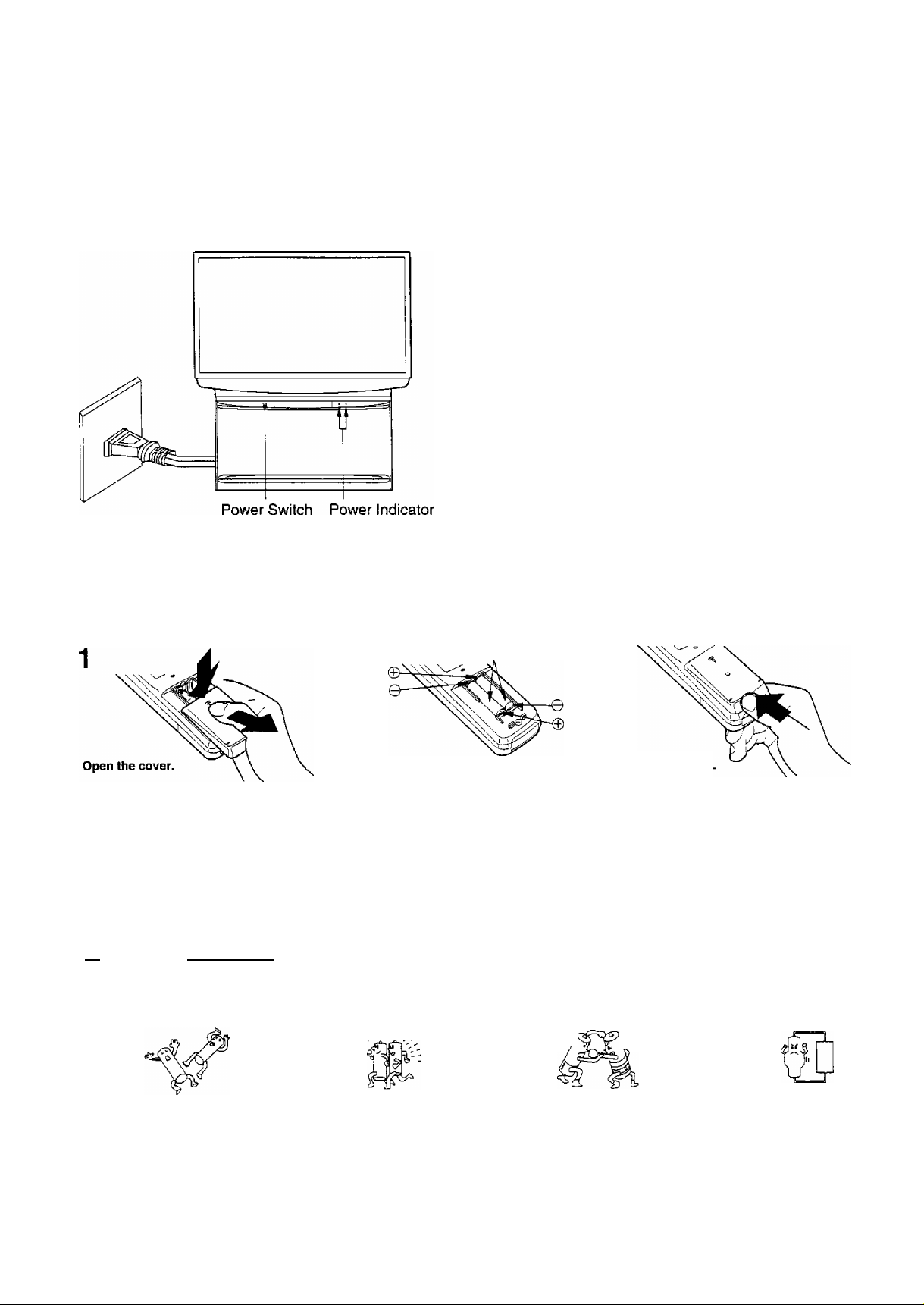
Connect the Piug to the Wall Outlet
Note:
Mains plug types vary between countries.The mains plug
shown at left may therefore not be the type fitted to your
set.
When connecting the mains plug to the wall outlet, on the
right side of power indicator will light (Red).
How to Turn the Power On
Push the Power Switch on the set to turn the set on.
The Power Indicator ((i)) left side will light.
Power-OFF........Indicator not illuminated
Stand-by (i)
Power-ON..........Green
Note:
When in the Stand-by condition (Refer to page 30), it is
possible to turn the TV set on by pushing the “Power
(Stand-by)” Button or the “Direct Programme Number
Selection” Buttons (0-9), Programme Number Up or Down
Buttons either on the TV set or Remote Control.
.......
Red
Battery Installation
Two “R6 {AA)" size
Batteries: Use two "R6 (AA)” size batteries.
Apply slight downward pressure while pulling
towards the bottom.
Do not use rechargeable (Ni-Cd) batteries.
They are different in shape and performance and may fail to ensure correct operation.
Insert the batteries ensuring correct polarity.
This is identifiable by the V and symbols
on both the batteries and inside the battery
compartment.
Replace the cover
A Battery cautions
The incorrect use of batteries can cause electrolyte leakage which will corrode the Remote Control or cause the
batteries to burst.
Old Batteries New Batteries
^// \w
Replace both batteries at the same time.
Don't mix battery types
{alkaline with carbon zinc, etc.)
Don’t Recharge.
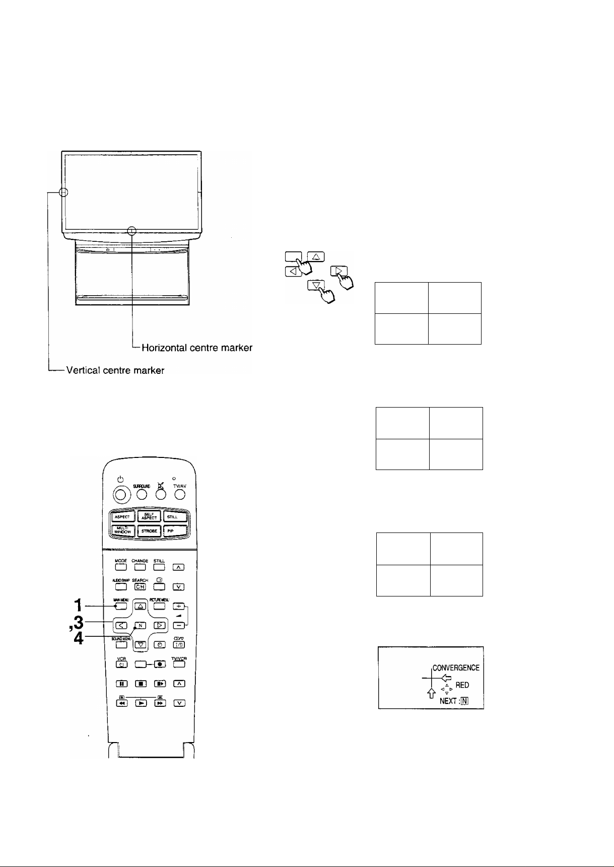
Convergence Adjustment
Prior to Adjustment, tuning the broadcast signal or input a
Video signal and operate the set for more than 60 minutes.
If the set location or direction is changed or moved, the set may
be affected by terrestrial magnetic fields, causing the colours
displayed to be out of alignment.
If this occurs, adjust the each ASPECT mode as indicated
below.
If it is needed, carry out the following procedure 1 through 9
and following have to be carried out once with PAL signal and
with NTSC signal.
1
2 [S
3 [s
MMNMENU
H]
Push the “MAIN MENU” and “Position”
Buttons, until the Features Menu to
“CONVERGENCE”.
CONVERGENCE
green
V ^
NEXT M
Use the Position Up, Down buttons of the
remote control to align the Horizontal Green
line and Vertical centre marker.
CONVERGENCE
<\gfieen
NEXT :[H]
Use the Position Right, Left buttons of the
remote control to align the vertical Green line
and Horizontal centre marker.
Vertical centre
marker
8
Open
%
CONVERGENCE
A green
NEXT:®
Push the “N” button of the remote control to
set the Red Adjustment mode, (store Green)
Horizontal centre
marker
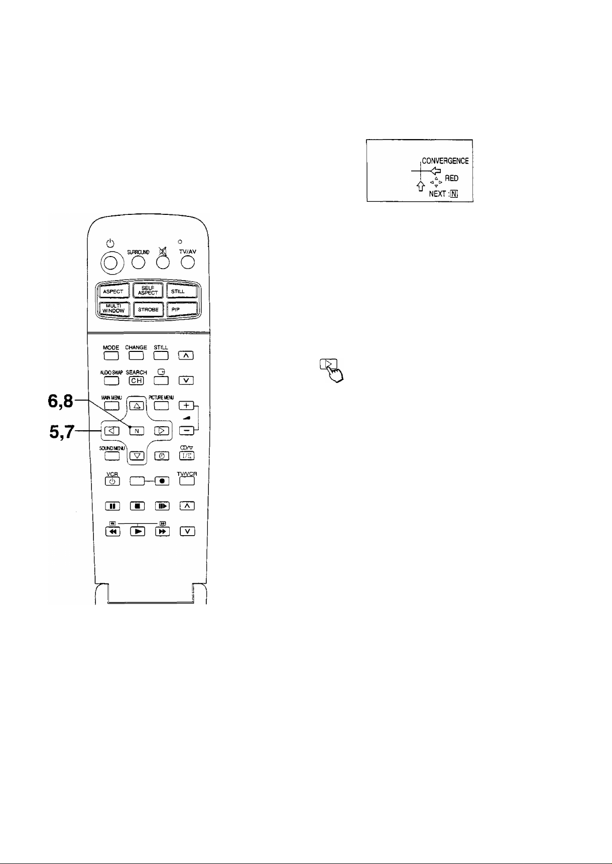
Convergence Adjustment
5 [^
H]
h:
o
%
Use the Position Up, Down, Right and Left
buttons of the remote controi to align the Red
and Green lines, (become Yellow line)
Push the “N” button of the remote control to
set the Blue adjustment mode, {store Red)
CONVERGENCE
BLUE
NEXT m
Use the Position Up, Down, Right and Left
buttons of the remote control to align the Blue
and Yellow lines, (become White line)
CONVERGENCE
____
^^Open
8
%
1 8
NEXT:
Push the “N" button of the remote control to
return to the original screen, (store Blue)
If you wish to view a video with a different
aspect mode (4 : 3, ZOOM1, ZOOM2, FULL,
JUST) or colour system (NTSC, PAL,
SEC AM), repeat steps 1-8 while the picture is
being displayed.
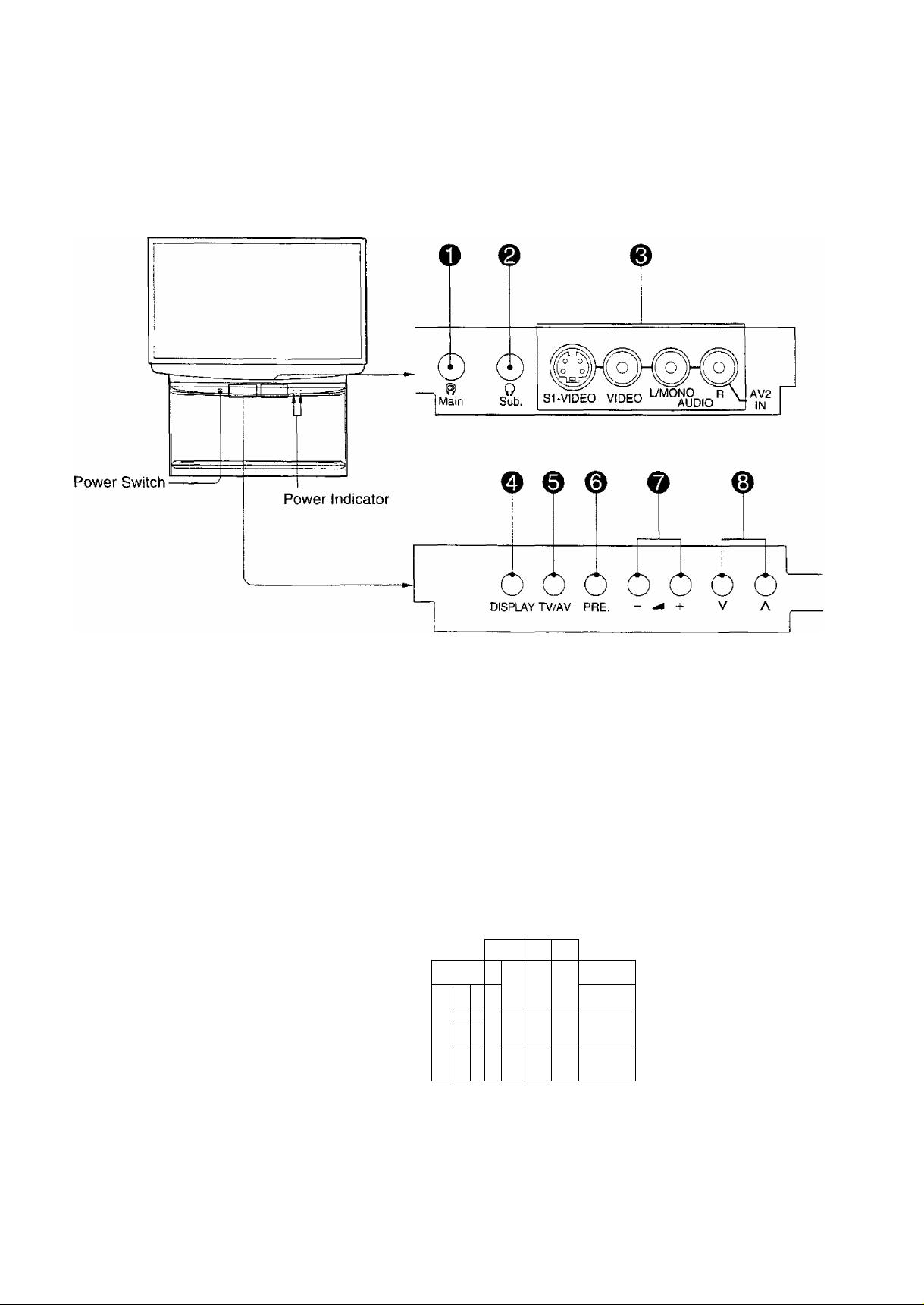
Lcx:ation of Controls
Controls and Terminals on the TV
! I
10
=:r:
E
w#m n»»i»ni imMiiii
ATTENUATOR
(For Service)
-----
SURPOOWiOlil
@
ir
&
©
(W-ieoj
^li
-911
^11
'lnWirTOR’
OLrr
© ©
C£)
'■*V3 '
№
w
0)0)
©
ie;
©
(si-video)
C VIPEO )
( AtJDID )
( HCKT )
.irt
Location of Controls
Item No.
O
0
0
o
0
0
0
0
Description/Function
Main Headphones Jack
Sub Headphones Jack
AV2 Input Terminals
Display
TV/AV Selection
Preset
Volume Up (+) and Down {-)
Programme Number Up (a) and
Down (v)
Refer to Page(s)
16
16
14
31
30
19, 20, 22
31
30
0
0
0
0
0
Aerial Terminal
(Also called the “RF In Terminal’
Surround Speaker Terminals
Monitor Output Terminals
AV1 Input Terminals
AV3 Input Terminals
,) 6
15
15
14
14
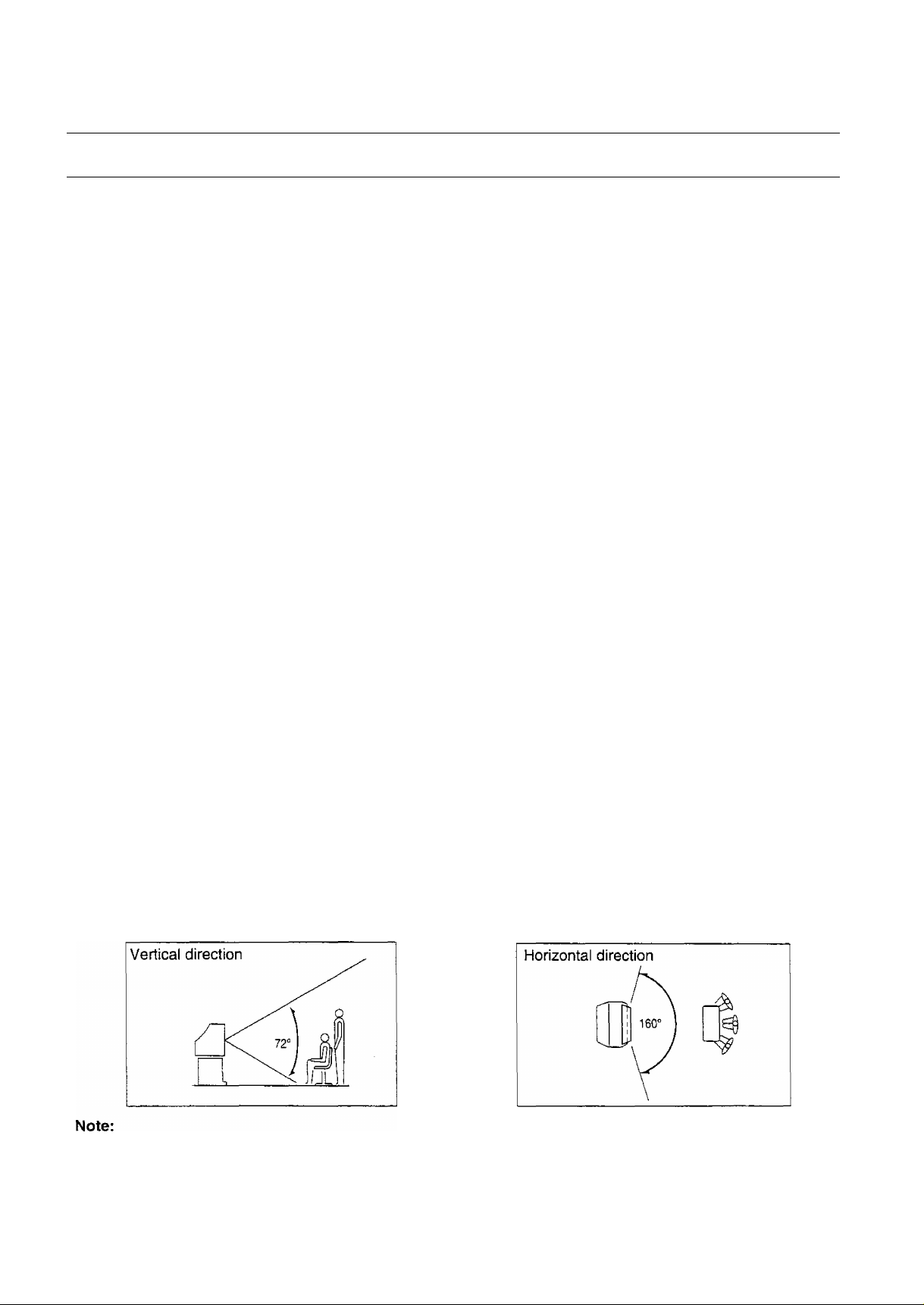
Viewing Angle
Please view the set within a vertial range of 72°, and a horizontal range of 160°, as indicated by the diagram below.
If the set is viewed outside of this range, the colours in the picture as a whole will be disorted, and you will be unable
to view the best picture the machine can deliver.
11
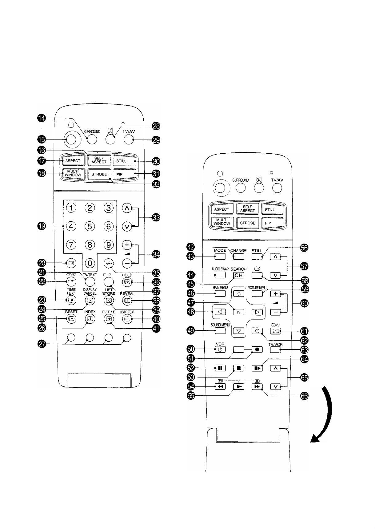
Location of Controls
Remote Control
12
Open

Location of Controls
Item
No.
€)
0
0
0
@)
0
0
0
0
0
0
0
0
0
Function
Surround Selection 44
Power (Stand-by) 30
SELF ASPECT
ASPECT
MULTI WINDOW 36
Direct Programme Number
Selection
Status Recall
TV/TEXT Selection
Stereo/Bilingual Sound Selection 42
Time Text
TEXT Display Cancel
TEXT Reset
TEXT Index
TEXT Colour-coded Buttons
Sound Mute
TV/AV Mode Selection
Refer to
Page(s)
38
34
30
31
53
55
54
53
53
53
31
30 Buttons for Sub picture
Item
No.
0
0
0
0
0
0
0
0
0
0
0
0
0
0
0
0
Function
Main/Sub picture Change 36,40
Sub picture TV/AV Mode Selection 37, 40
Audio Swap
Sub picture Channel Search
Main Menu Selection
Normalisation
Position Buttons
Sound Menu Selection
VCR Power
VCR Record
VCR Pause Still
VCR Stop
VCR Rewind/Review
VCR Play
Still
Programme Number Up and Down
Refer to
Page(s)
37, 41
37, 41
48
48
48
46
56
56
56
56
56
56
37, 41
37, 41
0
0
0
0
0
0
0
0
0
0
0
Still
Picture in Picture Selection
STROBE
Programme Number Up and Down 30
Volume Up and Down
Two Digit Programme Number
Selection
TEXT Hold
TEXT Favourite Page Selection 53
TEXT Reveal
TEXT List Store 53
TEXT LIST/F. TEXT
TEXT Futi/Top/Bottom Selection
37, 41
40
39
31
30
53
53
53
53
0
0
0
0
0
0
0
0
0
Recall
Picture Menu Selection
Volume Up and Down
Stereo/Bilingual Sound Selection
OFF Timer Selection
TV/VCR Mode Selection
VCR Still/Advance
VCR Programme Number Up and
Down Buttons
VCR Fast Forward /Cue
31
45
31
42
31
56
56
56
56
13
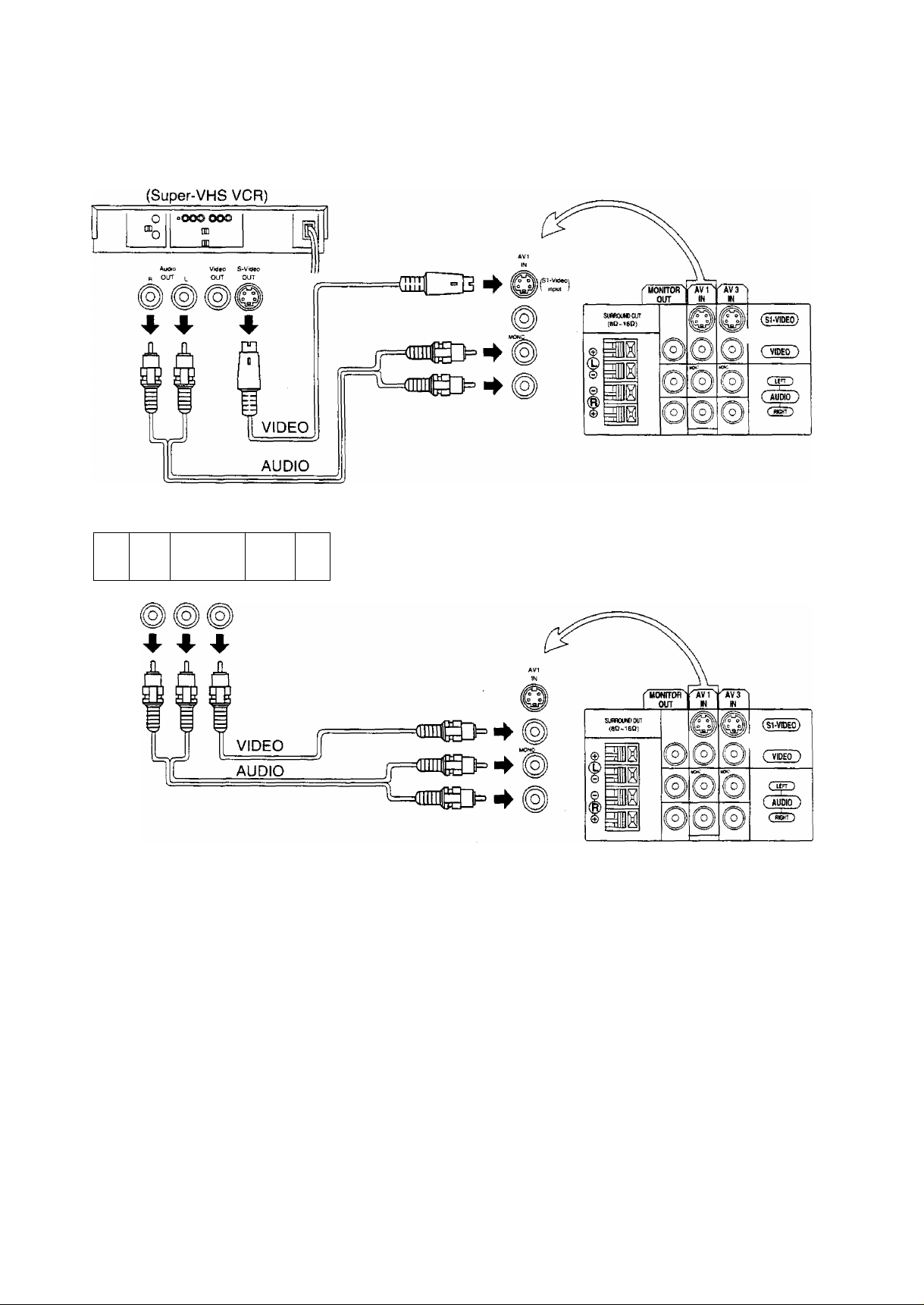
Connections
How to connect the “AVI, 2 or 3” Input Terminals.
(VHS VCR)
oOOD OOO
I
I
o
p OUT |_ OUT
m
n)
Audio Video
Note:
(1) When AVI, AV2 or AV3 is selected, and that AV mode has no input picture signal, the Background Colour of the
screen will change. (This only occurs if the Blue-Back function is set to the ON condition; refer to page 50 for
details.)
(2) When an S-Video cable is connected to the SI-Video terminal, the Phono Video input will be automatically
switched off for that AV mode.
(3) When a Monaural VCR is used, connect the Monaural Audio cable to the Audio “LEFT’ terminal.
(4) Simitar connections are available at the AVI, AV2 and AV3 input terminals.
Select the desired AV input position by pushing the TV/AV Mode selection button. (Refer to page 30)
S{Separator)1-Video Terminal
The S1-Video terminal on this set is a separator luminance (Y) and chrominance (C) signal terminal which supports
videos compatible with wide TV. When a full image from the S1 Video terminal of special video is detected by the
set, the screen size automatically sets to full. Connection is established with priority given to the S1-video when the
SI-video input terminal and the video input terminal are connected at the same time. Thus connection is not required
for video input. Also, when connecting, connect the audio mode at the same time.
14
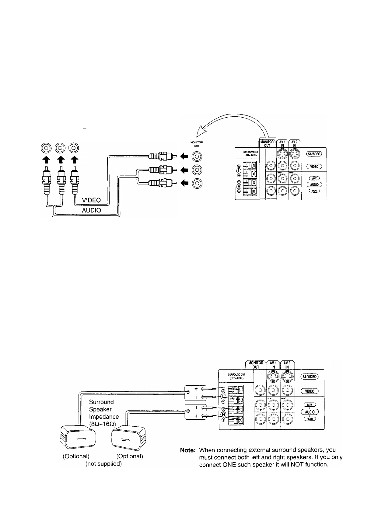
Connections
How to connect the AV MONITOR OUTPUT terminals to other equipment.
The MONITOR OUT terminals output the same signals as main picture on the TV screen and sound from the
speakers at that time, e.g. TV programmes or signals from AV1, AV2 or AV3 input.
Recording Equipment
(VHS VCR)
°oooooo
o
“b
m
_____
Note:
(1 ) Never connect the same video recorder with both the VIDEO IN and MONITOR OUT terminals on this TV set, as
this could cause incorrect operation.
(2) The monitor output emits the main picture normal video and audio signals.
(3) Teletext displays on screen will not be output at the MONITOR OUT terminals.
(4) Even if the set in multi window condition, MONITOR OUT terminais output the same signals as main picture on
the screen and sound from speakers. Sub picture including strobe, still, channel search, etc. will not be output at
the MONITOR OUT terminals.
Connecting Surround Speakers
Connect the surround speakers as follows.
The Surround effect is enhanced by connecting external surround speakers, (optional)
Although it is possible to enjoy the “Surround effect” with this TV set as it is, upon connecting separate “Surround
Speakers” the presence of the enveloping sound becomes more vivid.
15

I
Connections
Connecting Headphones
Connect headphones as follows.
You can listen to sound from each of the headphone plugs as shown below.
Screen condition
Single picture/
Teletext
Two Window/
Picture in Picture/
Picture out Picture
Two Window/
Picture in Picture/
Picture out Picture
CHANGE
Two Window/
Picture in Picture/
Picture out Picture
AUDIO SWAP
B i A
Speaker
Sound
A
(Stereo)
A
(Stereo)
B
[ffl
B
B la
B
(Stereo)
B
(Stereo)
Main
Headphones
A
(Stereo)
A
(Stereo)
(Stereo)
(Stereo)
Sub
Headphones
A
(Mono)
B
(Mono)
B
B
A
(Mono)
B
(Mono)
Monitor
Output
A
(Stereo)
A
(Stereo)
B
(Stereo)
A
(Mono)
Main Headphones plug:
When a Main Headphones plug is inserted into the Headphones socket all speakers will be automatically
disconnected: only the Main Headphones will function.
Use Volume Up or Down Button to control volume level.
Sub Headphones plug:
For the volume control, refer to page 49.
16
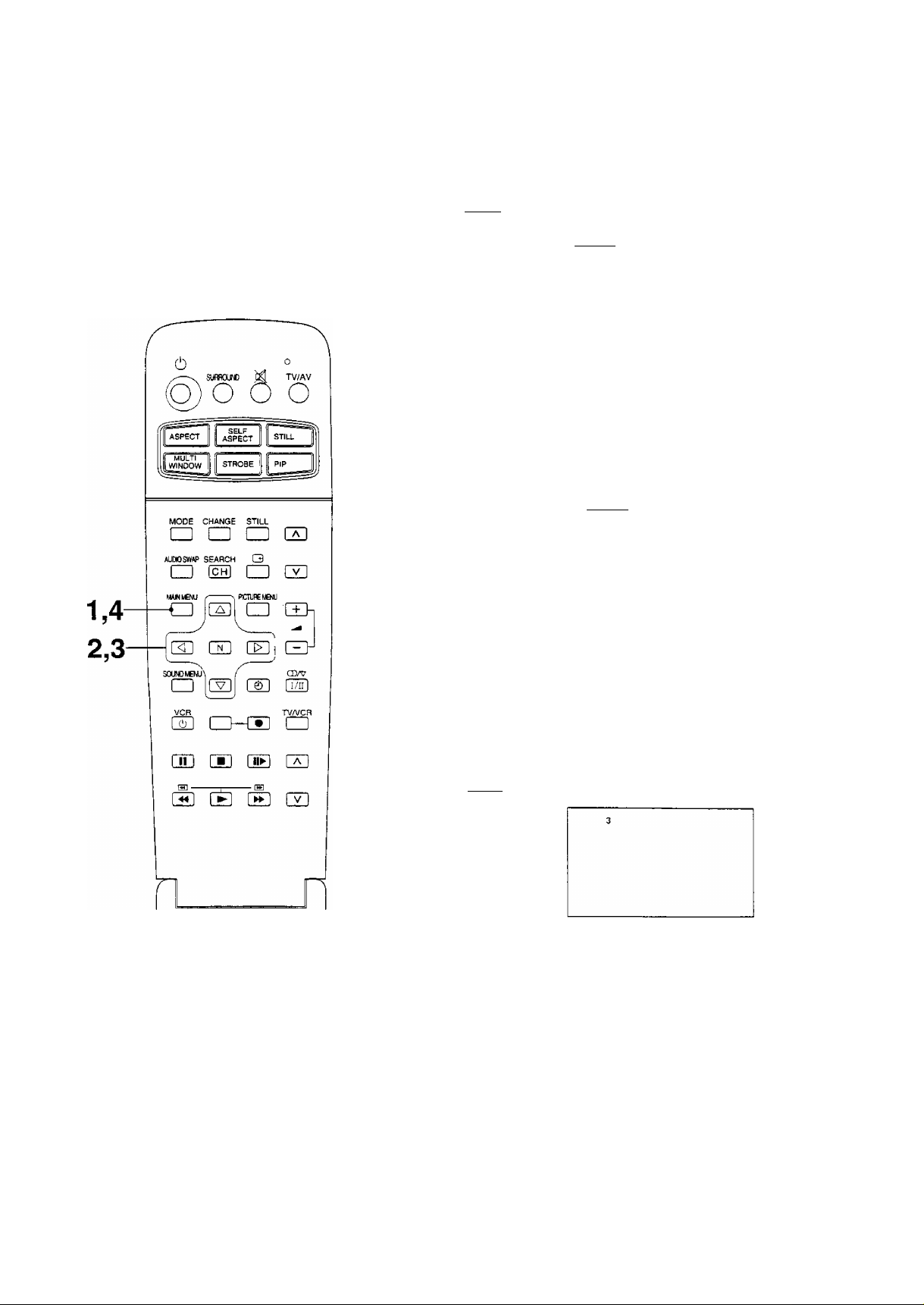
How to Select the LANGUAGE Function
Languages display on-screen can be selected by following method.
1
2 (s
3 (a
ca
MAIN MENU
5
H] ca
[V]
Push the “MAIN MENU” Button.
I
ASPECT
I
PICTURE
SOUND
FEATURES
PRESET
LANGUAGE
ENGLISH
'PSiS
Push the “Position Up or Down” Button until
your desired language position is reached.
ASPECT
PICTURE
SOUND
FEATURES
PRESET
[Language;
iENGLISH!
Push the “Position Left or Right’ Button. The
on-screen language display will change.
ASPECT
PICTURE
SOUND
FEATURES
PRESET
y^NGUAGEI
INC
^rOpen
MAIN MENU
Push the “MAIN MENU” Button again to
return to the normal viewing condition.
17
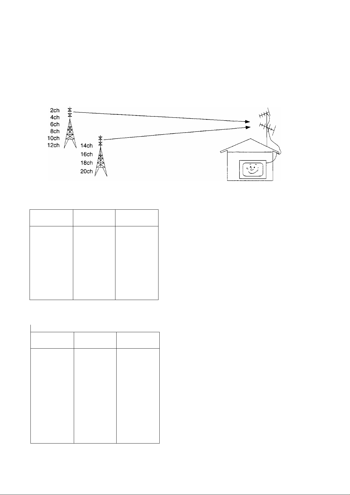
Tuning Procedure
Channel Selection
Select the most easily viewed channel selection method.
Example
Programme
Number
1
2
3
4
5
6
7
8
9
10
Channel
Display
2
4
6
8
10
12
14
16
18
20
Received
Channel
2
4
6
8
10
12
14
16
18
20
POSITION SELECT
When the Channel Selection is on POS. (Position), and
Auto Search is performed, the set memories the channels
searched in order from Programme No.1.
Push the button (T) to view channel 2.
Push the button (|) to view channel 4.
Push the button (3) to view channel 6.
During Position mode various reception channels can be
viewed.
Example
Programme
Number
.10
20
18
DIRECT SELECT
Channel
Display
1
2
3
4
5
6
7
8
9
2
- -
4
-
6
- -
8
- -
10
20
Received
Channel
2
4
-
6
8
10
20
When the Channel Selection is on DIRECT, and Auto
Search is performed, the set memories the programme
number which is the same as the channel searched.
This method allows you to select the desired channel by
pushing the channel display number directly on the
remote control to select the station. The channel display
numbers for the broadcast stations in each country are
listed on Page 21.
 Loading...