

Panasonic TX-47P800H User Manual

Operating Instructions
Wide Projection Television
TX-47P800HModel No.
Manufactured under license from BBE
Sound,Inc.
Licensed by BBE Sound,Inc.under
USP4638258, 5510752 and 5736897.
BBE and BBE symbol are registered
trademarks of BBE Sound,Inc.
Please read these instructions before operating your set and retain
them for future reference.
TQBC0542

Dear Panasonic Customer
Welcome to the Panasonic family of customers. We hope that you will have many years
of enjoyment from your new Wide Projection television set.
To obtain maximum benefit from your set, please read these Instructions
before making any adjustments, and retain them for future reference.
Retain your purchase receipt also, and note down the Model Number and
Serial Number of your set in the space provided on the rear cover of these Instructions.
Visit our Panasonic Web Site http://www.panasonic.co.jp/global/
Important Information
(1) The long time (max. 2 hours) use of a TV game on this set is not recommended, since the signal from the TV game
may cause damage to the picture projection tubes of the set.
(2) Do not allow a still picture to be displayed for an extended period, as this can cause a permanent after-image to
remain on the Projection TV screen.
Examples of still pictures include logos, video games, computer images and teletext.
If still picture cannot be avoided, reduce the brightness and contrast levels of the picture to minimize any damage
that might occur.
(3) In order to minimize any damage to the projection tubes, this set uses the PICTURE SHIFT function (Refer to page
23) to change (shift) the entire pictures approximately 2 mm every 15 minutes.
Table of contents
Warnings and Cautions.......................................... 3
Before Operating This Set ..................................... 5
Safety Precaution ........................................................... 5
Securing the casters ....................................................... 5
Connecting the Aerial Cable to the RF in Terminal ......... 5
Connecting Headphones ................................................ 5
Connecting the Plug to the Wall Outlet ........................... 6
How to Turn the Power On ............................................. 6
Battery Installation .......................................................... 6
Battery cautions .............................................................. 6
Location of Controls .............................................. 7
Controls and Terminals on the TV .................................. 7
Connections ............................................................ 8
How to connect the “AV1, 2, 3 or 4” Input Terminals ...... 8
How to connect the DVD Input Terminals ....................... 9
How to connect the AV Monitor Output Terminals to other equipment ....
General Operation ................................................ 10
On-Screen menu Display from Remote Control ..
Convergence Adjustment .................................... 14
Convergence Adjustment mode ................................... 14
Convergence 1 Adjustment for RED, BLUE and GREEN .
Convergence 2 Adjustment for RED and BLUE ........... 15
Tuning Channels ................................................... 15
Channel Selection ........................................................ 16
Channel Allocation ........................................................ 17
Automatic Tune............................................................. 18
Manual Tune ................................................................. 19
Fine Tuning ................................................................... 20
How to Cancel the Fine Tuning .................................... 20
Programme Number Skip ............................................. 20
12
14
How to Cancel the Skip Function ................................. 21
Sound System Selection (Different region use differing systems) ..
Colour System Selection (Different region use differing systems) .....
Owner ID ................................................................ 22
Setup Adjustment ................................................. 23
OFF TIMER .................................................................. 23
CH COLOUR SET ........................................................ 23
CHILD LOCK ................................................................ 23
BLUE BACK ................................................................. 23
ILLUMINATION............................................................. 23
FLICKER REDUCTION ................................................ 23
3D-COMB ..................................................................... 23
PICTURE SHIFT .......................................................... 23
VCR/GAME .................................................................. 23
9
COLOUR SYSTEM ...................................................... 23
Picture Adjustment ............................................... 24
Sound Adjustment ................................................ 26
Aspect Controls .................................................... 28
Multi Screen .......................................................... 29
Multi PIP ....................................................................... 29
TELETEXT ............................................................. 30
Advanced Remote Control Operation ................ 33
Stereo Bilingual Sound Selection ................................. 33
VCR / DVD Control ....................................................... 33
Manufacturer setting .................................................... 34
Troubleshooting ................................................... 35
Cleaning ................................................................ 35
Specifications ........................................ Back cover
21
21
2
Warnings and Cautions
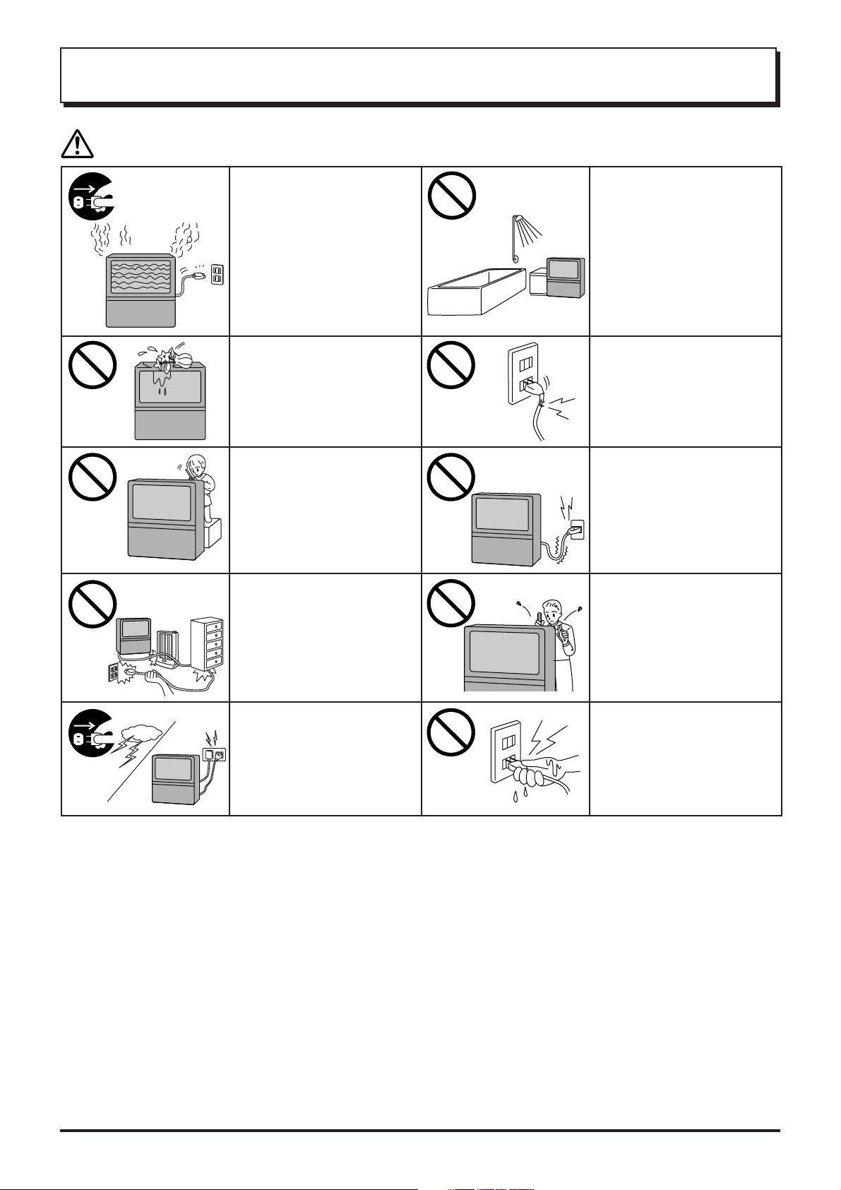
Warnings
Unplug the power cord in the
event of any malfunction
(screen goes blank, no sound,
odd sounds, smoke or unusual
odors coming from the unit).
Unplug the power cord if
foreign matter or water falls
into the unit, or if the unit is
dropped or the cabinet is
damaged.
DO NOT place any of the
following on the unit:
Flower vases, flower pots,
cups, small metal objects, or
cosmetics containers,
chemicals or water.
DO NOT insert foreign objects
(metal or easily flammable
objects).
TAKE CARE NOT to damage
the power cord.
DO NOT use this unit near
water. (Near a bath tub, etc.)
DO NOT use if the power cord
or power plug is damaged, or if
the plug does not fit tightly into
the socket.
DO NOT use at a voltage other
than indicated
DO NOT remove the rear cover
as live parts and High Voltage
components are accessible
when the rear cover is
removed.
DO NOT touch the aerial cable
and this unit when there is
lightning.
DO NOT touch the power plug
if your hands are wet.
3
Warnings and Cautions
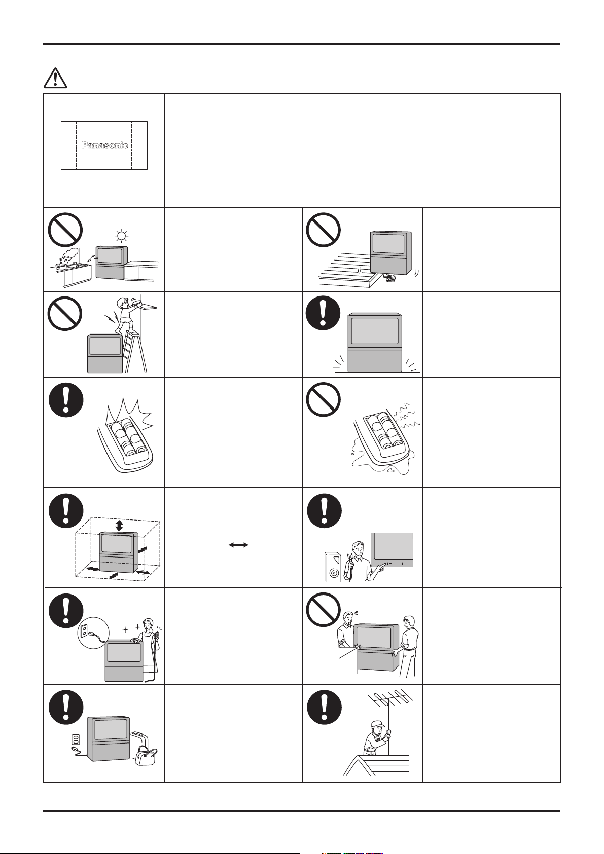
Cautions
Do not allow a still picture to be displayed for an extended period, as this can cause a
permanent after-image to remain on the Wide Projection TV screen.
Examples of still pictures include logos, video games, computer images, teletext and images
displayed in 4:3 mode.
Note:
After-images appear
The permanent after-image on the Wide Projection TV screen resulting from fixed image use
is not an operating defect and as such is not covered by the Warranty.
This product is not designed to display fixed images for extended periods of time.
DO NOT place in humid or
dusty location, or areas
exposed to smoke or steam.
DO NOT place in direct
sunlight and other sources of
direct heat.
DO NOT stand, or place
heavy objects on the unit.
Particular care should be
taken by families with small
children.
When inserting batteries,
ensure that the polarities
(positive and negative) are
correctly aligned. Insert as
shown on remote control. If
inserted incorrectly, battery
fluid may leak, and fire, injury,
or damage to surrounding
components may result.
Adequate ventilation is
essential to prevent failure of
electrical components, we
recommend that a gap of at
least 10 cm ( ) is left all
around this unit even when it
is placed inside a cabinet or
between shelves.
DO NOT place in an unstable
location.
Place in a safe location.
Fix the TV to a wall.
(refer to page 5)
Do not mix new and old
batteries. Use only the
specified batteries. Failure to
follow this precaution may
result in leakage of battery
fluid. Fire, injury, or damage to
surrounding components may
also result.
Turn the power “Off” before
connecting other electrical
equipment.
Before cleaning, unplug the
power plug from the socket.
Unplug the power plug from
the socket if you are not going
to use the unit for an extended
period.
To ensure continued excellent performance by this product, periodic cleaning is recommended. See page 35 for more information.
DO NOT Jolt the unit.
Ask your sales outlet to install
the aerial.
4
Before Operating This Set
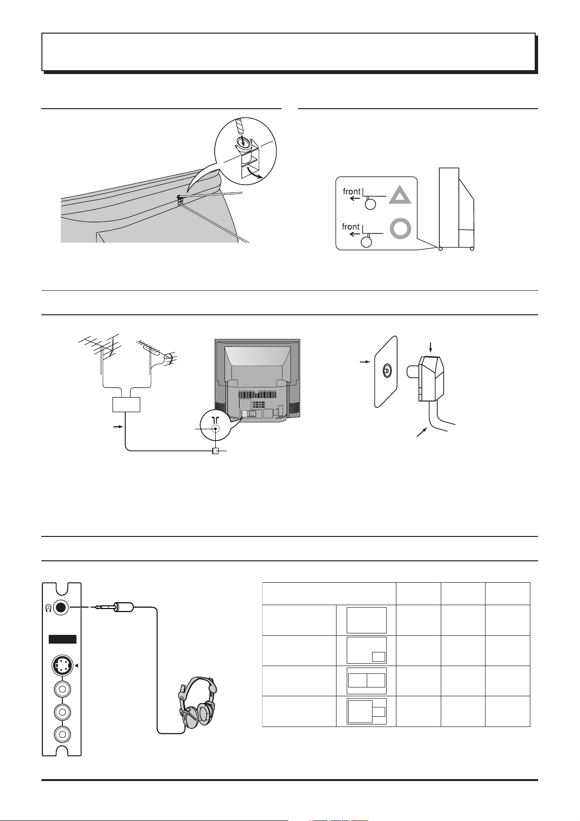
Securing the castersSafety Precaution
Please take safety precautions to
prevent the unit form falling over.
The unit may fall over during
earthquakes, or if someone stands on
or shakes the TV.
Fixing to a wall
Use a strong rope or a chain to fasten the TV firmly to a
strong support such as a wall or a pillar.
To prevent the set from tipping forward, turn the two casters on
the front of the TV so they face forward, as shown in the picture.
Connecting the Aerial Cable to the RF in Terminal
VHF Aerial
Mixer
UHF Aerial
Coaxial aerial plug
RF in
Terminal
75 Ohm
Coaxial Cable
To obtain optimum quality picture and sound, an Aerial, the correct cable (75 Ohm coaxial) and the correct terminating plug are required.
If a communal Aerial system is used, you may require the correct connection cable and plug between the wall Aerial socket and your set.
Your local Television Service Centre or Dealer may be able to assist you in obtaining the correct Aerial system for your particular area and
accessories required.
Any matters regarding Aerial installation, upgrading of existing systems or accessories required, and the costs incurred, are the
responsibility of you, the Customer.
RF in Terminal
Coaxial Aerial Plug
75 Ohm Coaxial Cable
Connecting Headphones
Connect headphones as follows.
(3.5mm Plug)
AV3 IN
S-VIDEO
VIDEO
MONO
L
AUDIO
R
(Optional)
(not supplied)
You can listen to sound from the headphones plugs as shown below.
Screen condition
Single
picture/Teletext
Picture in
Picture
Picture and
Picture
Picture on
Picture
Headphones plug:
When a Headphones plug is inserted into the Headphones socket, all speakers
will be automatically disconnected; only the Headphones will function
Use Volume Up “+” or Down “-” button to control volume level.
A
A
BA
A
Speaker
Sound
(Stereo)
(Stereo)
B
(Stereo)A(Stereo)
B
(Stereo)A(Stereo)A(Stereo)
A
A
A
A
Headphones
A
(Stereo)
A
(Stereo)
Monitor
Output
A
(Stereo)
A
(Stereo)
A
(Stereo)
.
5
Before Operating This Set
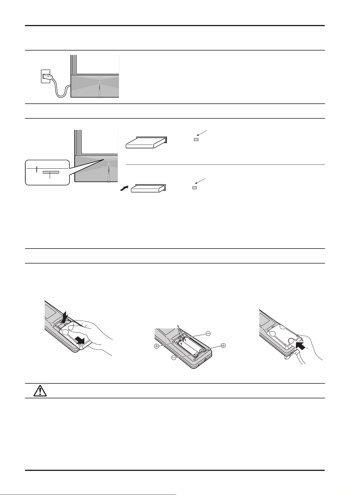
Connecting the Plug to the Wall Outlet
Notes:
• Main plug types vary between countries. The main plug shown at left may therefore
not be the type fitted to your set.
• The On/Off switch on this model does not full disconnect the TV from the mains
supply.
How to Turn the Power On
Power OFF
Note: Even when the Power Switch is "OFF", the TV set
Power Indicator
Push the Power switch on Television to turn the set on.
Power Switch
Notes:
• When in the Stand-by condition (Refer to page 11), it is also possible to turn the TV set on by pressing any of the “Direct
Programme Number Selection buttons” (0 - 9) or “Programme Number Up or Down buttons” on the TV set or on the Remote
Control.
If the Wall Outlet is switched OFF or the Main Plug is unplugged, when the TV set is again turned ON (by either connecting the
•
Main Plug to the Wall Outlet or switching the Wall Outlet ON), it will have returned to the original state.
Power ON
will still consume a small amount of power.
Power Indicator
No light: Power OFF condition
Power Indicator
No light: Normal viewing condition
Red : Stand by
Battery Installation
Open the cover.
1
Apply slight downward pressure
while pulling towards the bottom.
2 Batteries: Use two “R6 (AA)” size
batteries.
Insert the batteries ensuring the correct
polarities.
This is identifiable by the “+” and “−” symbols
on the batteries and inside the battery
compartment.
Two “R6 (AA)” size
3 Replace the cover.
Do not use rechargeable (Ni-Cd) batteries.
They are different in shape and performance and may fail to ensure correct operation.
Battery cautions
The incorrect use of batteries can cause electrolyte leakage which will corrode the Remote Control or cause the
batteries to burst.
Observe the following precaution:
1. Batteries shall always be replaced as a pair. Always use new batteries when replacing the old set.
2. Do not combine a used battery with a new one.
3. Do not mix battery types (example:“Zinc Carbon” with “Alkaline”).
4. Do not attempt to charge, short-circuit, disassemble, heat or burn used batteries.
5. Battery replacement is necessary when remote control acts sporadically or stops operating the TV set.
6
Location of Controls
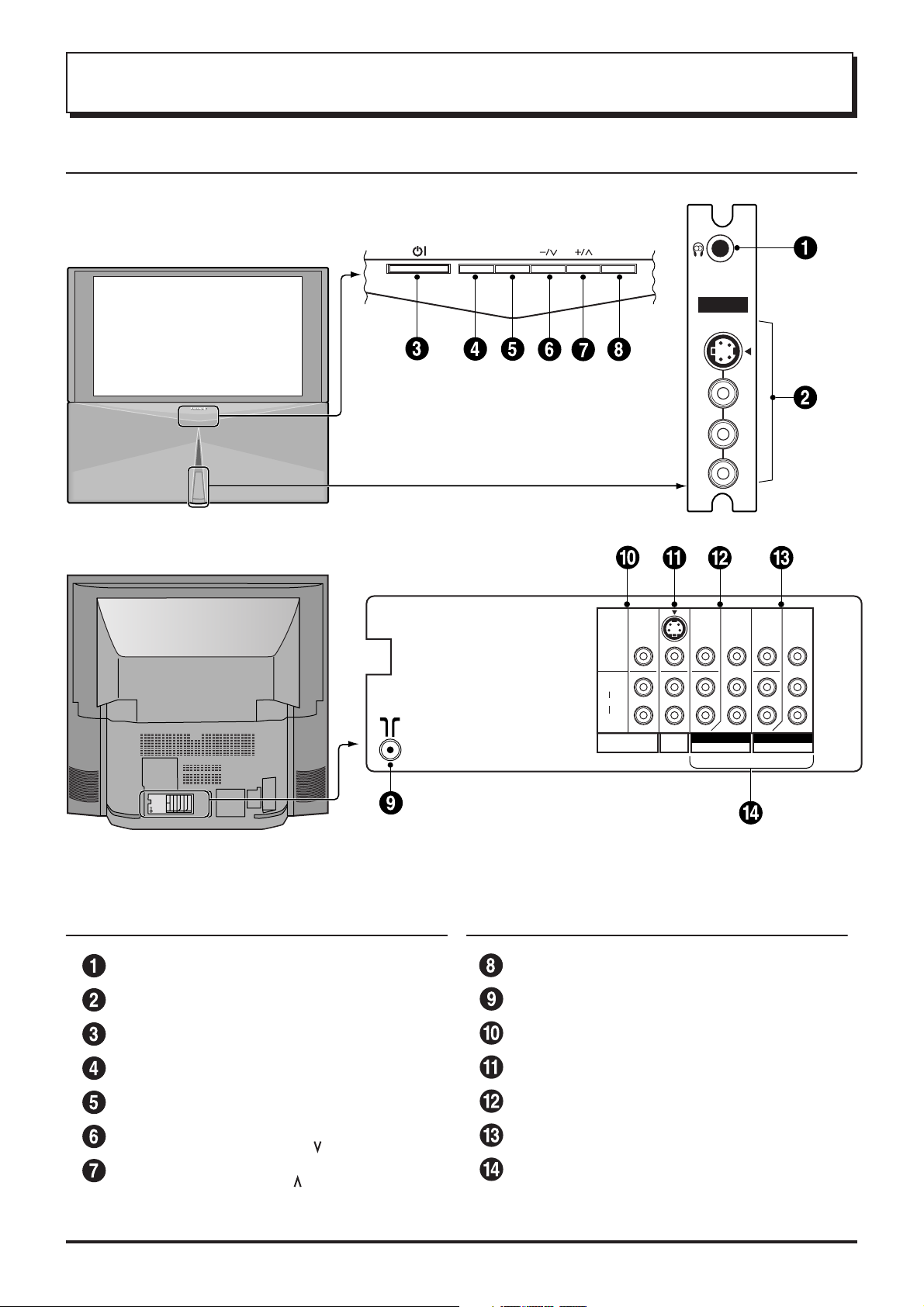
Controls and Terminals on the TV
STR
F
TV/AV
AV3 IN
S-VIDEO
VIDEO
MONO
L
AUDIO
R
S-VIDEO
VIDEO
L
AUDIO
R
MONITOR
OUT
Y
MONO
P
MONO
AV1
IN
B
P
R
I COMPONENT I COMPONENT
AV2 IN AV4 IN
MONO
Y
P
B
P
R
Item
No.
Function Refer to
Headphones Jack 5
AV3 Input Terminals 5
Power Switch 10
STR 10
Function Selection 10
Volume Down (−) /
Programme Number
Volume Up (+) /
Programme Number
Down ( )
Up ( )
Page
10
10
Item
No.
Function Refer to
Page
TV/AV Selection 10
Aerial Terminal (RF In Terminal) 5
Monitor Output Terminals 9
AV1 Input Terminals 8
AV2 Input Terminals 8
AV4 Input Terminals 8
DVD ( Y. P
B
. PR ) Input 9
7
Connections
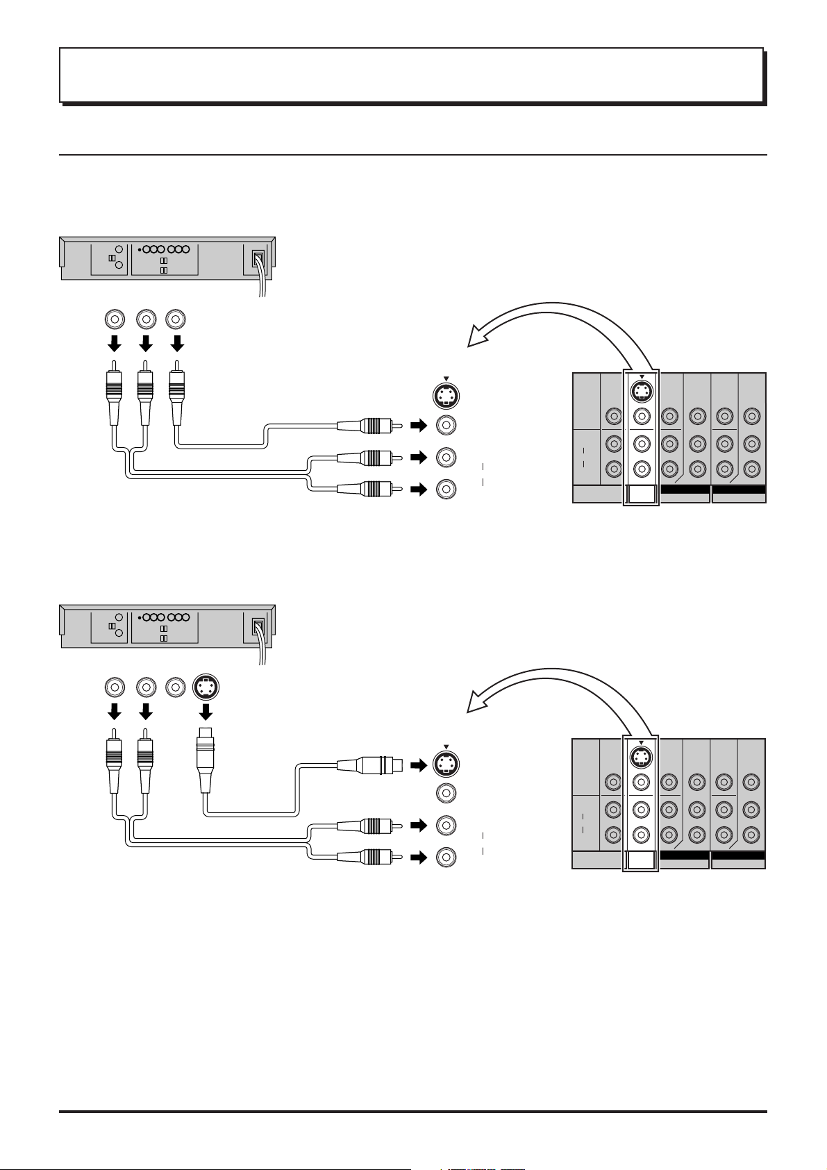
How to connect the “AV1, 2, 3 or 4” Input Terminals
Connect VCRs and other peripheral equipment
(VHS VCR)
Audio
OUT
RL
Video
OUT
VIDEO
AUDIO
(Super-VHS VCR)
Audio
OUT
RL
Video
OUT
S Video
OUT
MONO
AV1
IN
S-VIDEO
VIDEO
L
AUDIO
R
S-VIDEO
VIDEO
L
AUDIO
R
MONITOR
OUT
Y
MONO
P
MONO
AV1
IN
B
P
R
I COMPONENT I COMPONENT
AV2 IN AV4 IN
MONO
Y
P
B
P
R
S-VIDEO
VIDEO
L
AUDIO
R
MONITOR
OUT
Y
MONO
MONO
AV1
IN
PB
PR
I COMPONENT I COMPONENT
AV2 IN AV4 IN
MONO
Y
PB
PR
AUDIO
VIDEO
MONO
AV1
IN
S-VIDEO
VIDEO
L
AUDIO
R
Notes:
• When an S-Video cable is connected to the S-Video terminal, the corresponding Video input will be switched off and the signal
from the S-Video input will be used.
• When a Monaural VCR is used, connect the Monaural Audio cable to the Audio “L” (Left) terminal.
• Select the desired AV input position by pressing the TV/AV button. (Refer to page 10)
• Input 3 is located on the front of the unit.
• The AV2 and AV4 audio input terminals serve as the audio input terminal for both the Video input and the DVD input.
8
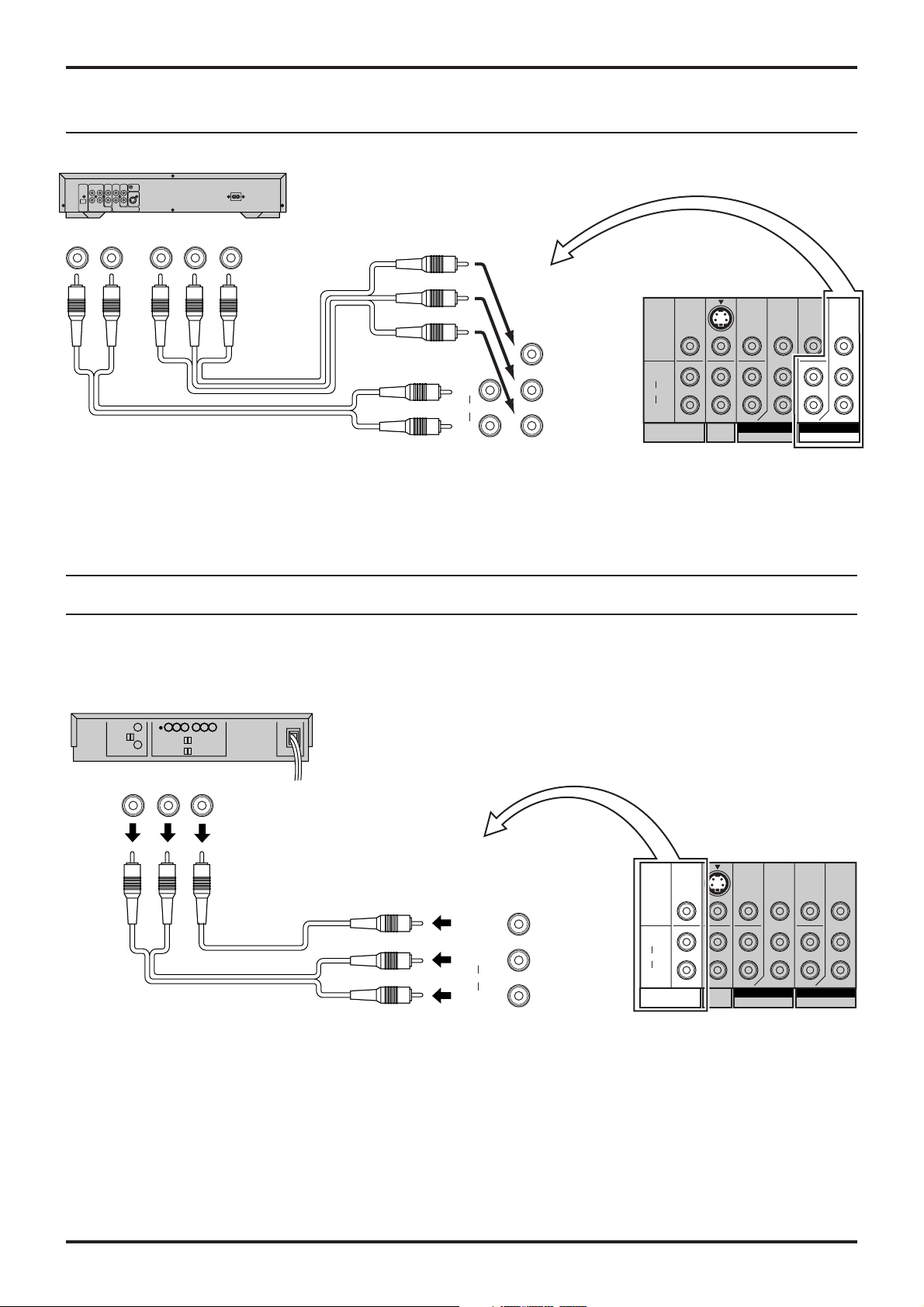
How to connect the DVD Input Terminals
DVD Player
Connections
Audio
OUT
LR
DVD(
Y-PB-P
R
) OUT
R
P
PBY
S-VIDEO
MONO
L
AUDIO
R
Y
P
B
P
R
VIDEO
L
AUDIO
R
MONITOR
OUT
MONO
AV1
IN
Y
MONO
PB
PR
I COMPONENT I COMPONENT
AV2 IN AV4 IN
MONO
Y
PB
PR
Notes:
• The AV4 audio signal is common for both AV4 and DVD input signal terminals.
• The DVD signal input terminal takes priority over the AV4 video signal input terminal.
• Similar connection are available at the COMPONENT VIDEO input 2 terminal.
How to connect the AV Monitor Output Terminals to other equipment
The “Monitor Out” Terminals output the same signals as main picture on the TV screen and sound from the speaker at that time, e.g.
TV programmes or signals from AV1, AV2, AV3 or AV4 input.
Recording Equipment
(VHS VCR)
Audio
RL
Video
IN
IN
VIDEO
AUDIO
S-VIDEO
VIDEO
L
AUDIO
R
MONITOR
OUT
S-VIDEO
VIDEO
L
AUDIO
R
MONITOR
OUT
Y
MONO
MONO
AV1
IN
PB
PR
I COMPONENT I COMPONENT
AV2 IN AV4 IN
MONO
Y
PB
PR
Notes:
• Never connect the same video recorder with both the VIDEO IN and MONITOR OUT terminals on this TV set, as this could cause
incorrect operation.
• The monitor output emits the main picture normal video and audio signals.
• Teletext display on screen will not be output at the MONITOR OUT terminals.
• Even if the television is in picture-in-picture condition, MONITOR OUT terminals output the same signals as main picture on the
screen and sound from speakers. Sub picture including strobe, still, channel search, etc. will not be output at the MONITOR OUT
terminals.
• The DVD signal (Y, P
B, PR) is not output at the MONITOR out terminals.
9
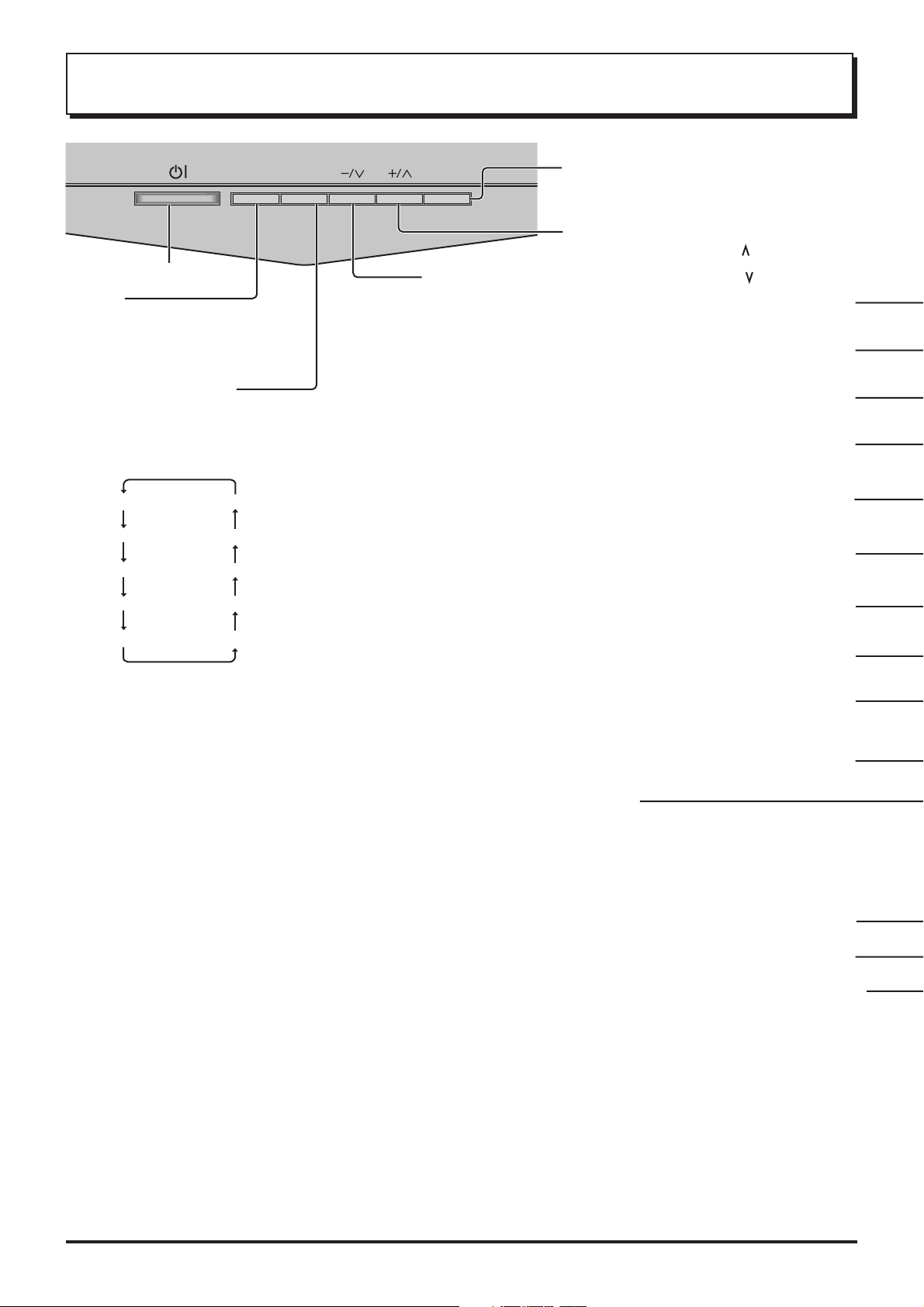
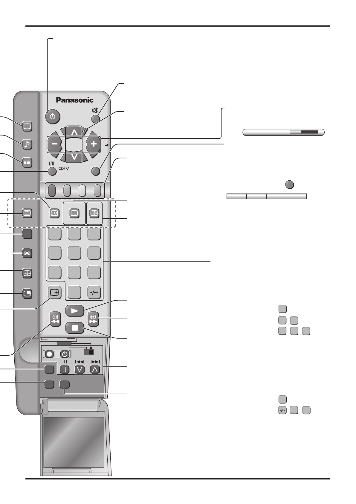
General Operation
STR
Power switch
STR
Used to store tuning and other
function settings. Also used to start
the menu demonstration.
Function selection
Displays the on screen display functions, use repeatedly to
select from the available functions.
The following adjustments can be accessed directly.
VOLUME
CONTRAST
BRIGHTNESS
COLOUR
TUNING MODE
BALANCE
TREBLE
BASS
F
Notes:
• TINT:
Displayed when receiving NTSC
and YUV625i signals.
• TUNING MODE :
Not displayed during AV mode.
TV/AV
Volume Down (-) / Programme Number Down ( )
TV/AV Selection
Press to select TV, AV1, AV2, AV3 and
AV4 input signal modes sequentially.
Volume Up (+) /
Programme Number Up ( )
Picture Menu (see page 12, 24)
Sound Menu (see page 12, 26)
Set up Menu (see page 13, 23)
Stereo/Bilingual Sound Selection
TEXT Favorite Page Selection
TV/TEXT Selection (see page 30, 31)
100Hz/PROGRE (see page 25)
(see page 33)
(see page 31)
SHARPNESS
TINT
Surround (see page 26, 27)
Aspect Controls (see page 28)
Press to select the different Aspect
options.
Picture in Picture Selection
(see page 29)
Recall
Press to display the current system status,
for example, Programme number, Channel
number, Stereo mode, Picture menu,
Sound menu, Scan mode, Sound system
and colour system.
VCR/DVD Rewind/Review
Normalization (see page 25, 27)
Store
(see page 18, 19, 20, 21, 31)
Stores some settings in TUNING
menus and TELETEXT.
10
General Operation
PICTURE
SOUND
SET UP
TV/TEXT
100Hz/
PROGRE
SURROUND
ASPECT
MULTI
PIP
Power (Stand-by) (see page 6)
The TV set must first be plugged into the wall
outlet and turned on at the power switch.
Press this button to turn the TV set On from
Standby mode, press it again to turn the TV set
OFF to Standby mode.
Sound Mute
Press to mute the sound completely the “Mute” symbol will appear.
Press again to restore the previous sound level, and cancel the mute.
Programme Number Selection
Press to select the next higher or
lower Programme number.
Coloured buttons used for
Multi Screen functions
(see page 29)
Teletext functions (see page 30)
AV selection (see page 11)
TEXT Index (see page 32)
TEXT hold (see page 31)
/Still (see page 29)
F. P.
CH SEARCH
TV/AV
INDEX HOLD
STILL
1 2 3
456
789
0
VCR/DVD Play
VCR/DVD
Fast Forward/cue
DVD
REC-VCR
N
STR HELP
?
VCR/DVD Stop
VCR/DVD Control
(see page 33)
Help (see page 12)
Note:
• It is also possible to turn the TV set on from STANDBY
mode by pressing the “Direct Programme Number
Selection” Buttons (0-9) and the “Programme Number
Up or Down” Button, either on the set or on the
Remote Control.
Volume Adjustment
Press to increase or decrease the sound
volume level.
VOLUME 18
TV/AV Mode Selection
Press to select TV, AV1, AV2, AV3 and
AV4 input signal modes sequentially.
Remote control :
AV1 AV2 AV3 AV4
Press to display AV1 - AV4 at the
bottom of the screen. Each coloured
button corresponds to each input
signals. For example, pressing the Red
button selects AV1.
TV/AV
Direct programme Number
• Direct Programme Number Selection
(CH SELECT = DIRECT)
You can select the number directly by
pressing the corresponding programme
number buttons.
Programme Number 8.......
Programme Number 36..... ,
Programme Number 124... , ,
• Direct Programme Number Selection
(CH SELECT = POSITION)
(Other than Australia)
You can select the numbers directly by
pressing “Number 0-9” buttons or by
pressing “Two Digit” and “Number 0-9”
buttons.
Programme Number 8 .....
8
3
1
8
6
2
4
Programme Number 12.... , ,
Note:
• When the Skip setting for Programme
Number 100 through 125 is on, the
channel selection time will be shortened,
and thus you can not input three digits at
a time.
1
2
11
 Loading...