

TX --- 36PD30
Colour Television
(U.K. Standard)
Operating
Instructions
TQB8E3925
Welcome
Dear Panasonic Customer,
We hope that you have many years of enjoyment from your new TV. The
bookwillallowyoutousetheTVasquicklyaspossible.Werecommendthatyouthenreadthecompleteinstructionbook,andkeepit
to refer to as you explore the range of advanced features that this TV offers.
QuickStart Guide
section at the beginning of this instruction
This TV has a low power consumption making it very cost effective to run. Also, when in
power consumption is merely 0,5W.
MADE FROM
100% RECYCLED PAPER
This instruction book is produced using recycled paper, made from 100% Post---consumer waste pulp.
De---inked without bleaching. Free from optical brightening agents (OBA).
Contents
Warnings and Precautions 3........................
Accessories 4....................................
Fitting remote control batteries 4....................
Basic controls: front panel and remote control 5......
Quick Start Guide 6...............................
Using the On Screen Displays 12...................
Standby
Still 27............................................
Q---Link 28........................................
Tuning your VCR and satellite receiver 29.............
VCR / DVD operation 30............................
Teletext operation 31...............................
Audio / video connections 33........................
mode the
Picture menu 13..................................
Sound menu 14..................................
Setup menu 15...................................
Tuning menu --- overview 16........................
Programme edit 17.............................
Auto setup 19.................................
Manual tuning 20..............................
Shipping condition 21..........................
Owner ID 22...................................
Aspect controls 23................................
Multi window 26..................................
Channel search 27................................
Picture and text 27................................
Front sockets 33................................
Rear sockets 34................................
Troubleshooting 35.................................
Scart and S---video socket information 36.............
Specifications 36...................................
2
Warnings and precautions
D
This TV set is designed to operate on 220--240V, 50Hz A.C.
D
To prevent fire, never place any type of candle or naked
flame on top of, or near the TV set.
D
To prevent damage which might result in electric shock or
fire, do not expose this TV set to rain or excessive moisture.
This TV must not be exposed to dripping or splashing water
and objects filled with liquid, such as vases, must not be
placed on top of or above the TV.
D
WARNING : HIGH VOLTAGE !!!
Do not remove the rear cover as live parts are accessible
when it is removed. There are no user serviceable parts
inside.
D
TV Games / Home Computers
Extended use of TV games or home computers with any
television set can cause a permanent ‘shadow’ on the
screen.Thistypeofirreversiblepicture tube damage, can be
limited by observing the following points:
D
Reduce the brightnessand contrast levelsto a minimum
viewing level.
D
Do not operate the television set for a continuous period
of time while using TV games or home computers.
D
This type of picture tube damage, is not an operating
defect, and as such is not covered by the Panasonic
warranty.
D
The On/Off switch on this model does not fully disconnect
the TV from the mains supply. Remove the mains plug from
the wall socket before connecting or disconnecting any
leads or if the TV set is not used for a prolonged period of
time.
Note:
D
If the set is not switched off when the TV station stops
transmitting, it will automatically go to standby mode
after 30 minutes. This function will not operate when the
TV is in AV mode.
D
Cabinet and picture tube care
Remove the mains plug from the wall socket. The cabinet
and picture tube can be cleaned with a soft cloth moistened
with mild detergent and water. Do not use solutions
containing benzol or petroleum. TV sets can produce static
electricity, care must be taken whenever touching the TV
screen.
D
Adequate ventilation is essential to prevent failure of
electrical components, werecommend that a gap of at least
5cm is left all around this television receiver even when it is
placed inside a cabinet or between shelves.
D
Avoid exposing the TV set to direct sunlight and other
sources of heat. To prevent fire, never place any type 0f
candle or naked flame on top or near the TV set.
FOR YOUR SAFETY PLEASE READ THE FOLLOWING TEXT CAREFULLY
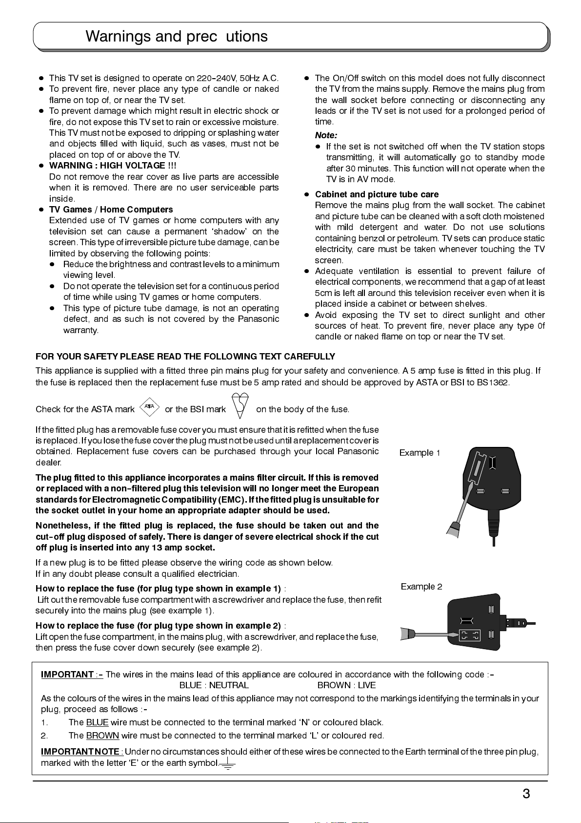
This appliance is supplied with a fitted three pin mains plug for your safety and convenience. A 5 amp fuse is fitted in this plug. If
the fuse is replaced then the replacement fuse must be 5 amp rated and should be approved by ASTA or BSI to BS1362.
Check for the ASTA mark
If the fitted plug has a removablefuse cover youmust ensure thatit is refitted when thefuse
isreplaced.If you lose the fuse cover the plug must notbeuseduntil a replacement cover is
obtained. Replacement fuse covers can be purchased through your local Panasonic
dealer.
The plug fitted to this appliance incorporates a mains filter circuit. If this is removed
or replaced with a non--filtered plug this television will no longer meet the European
standards for Electromagnetic Compatibility (EMC). If thefitted plugis unsuitablefor
the socket outlet in your home an appropriate adapter should be used.
Nonetheless, if the fitted plug is replaced, the fuse should be taken out and the
cut--off plug disposed of safely. There is danger of severe electrical shock if the cut
off plug is inserted into any 13 amp socket.
If a new plug is to be fitted please observe the wiring code as shown below.
If in any doubt please consult a qualified electrician.
How to replace the fuse (for plug type shown in example 1)
Lift out theremovable fuse compartment with a screwdriver andreplace the fuse, then refit
securely into the mains plug (see example 1).
How to replace the fuse (for plug type shown in example 2)
Liftopenthefusecompartment,inthemainsplug,with a screwdriver, and replace the fuse,
then press the fuse cover down securely (see example 2).
ASA
or the BSI mark on the body of the fuse.
:
:
Example 1
Example 2
IMPORTANT
As the colours of the wires inthe mains lead of this appliance may not correspond to the markings identifying the terminals in your
plug, proceed as follows :
1. The BLUE wire must be connected to the terminal marked ‘N’ or coloured black.
2. The BROWN
IMPORTANTNOTE
marked with the letter ‘E’ or the earth symbol.
:--The wires in the mains lead of this appliance are coloured in accordance with the following code :
BLUE : NEUTRAL BROWN : LIVE
--
wire must be connected to the terminal marked ‘L’ or coloured red.
: Under no circumstances shouldeither ofthese wiresbe connectedto theEarth terminalof thethree pinplug,
--
3
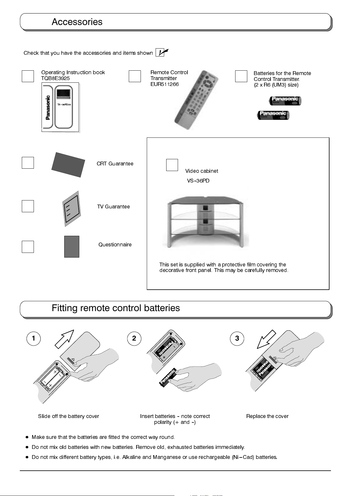
Accessories
Check that you have the accessories and items shown
Operating Instruction book
TQB8E3925
T X --- 3 6 P D 3 0
CRT Guarantee
TV Guarantee
n
Remote Control
Transmitter
EUR511266
Batteries for the Remote
Control Transmitter.
(2 x R6 (UM3) size)
Video cabinet
VS--36PD
Questionnaire
This set is supplied with a protective film covering the
decorative front panel. This may be carefully removed.
Fitting remote control batteries
1
2 3
Replace the coverSlide off the battery cover Insert batteries--note correct
polarity (+ and--)
D
Make sure that the batteries are fitted the correct way round.
D
Do not mix old batteries with new batteries. Remove old, exhausted batteries immediately.
D
Do not mix different battery types, i.e. Alkaline and Manganese or use rechargeable (Ni---Cad) batteries
4
.
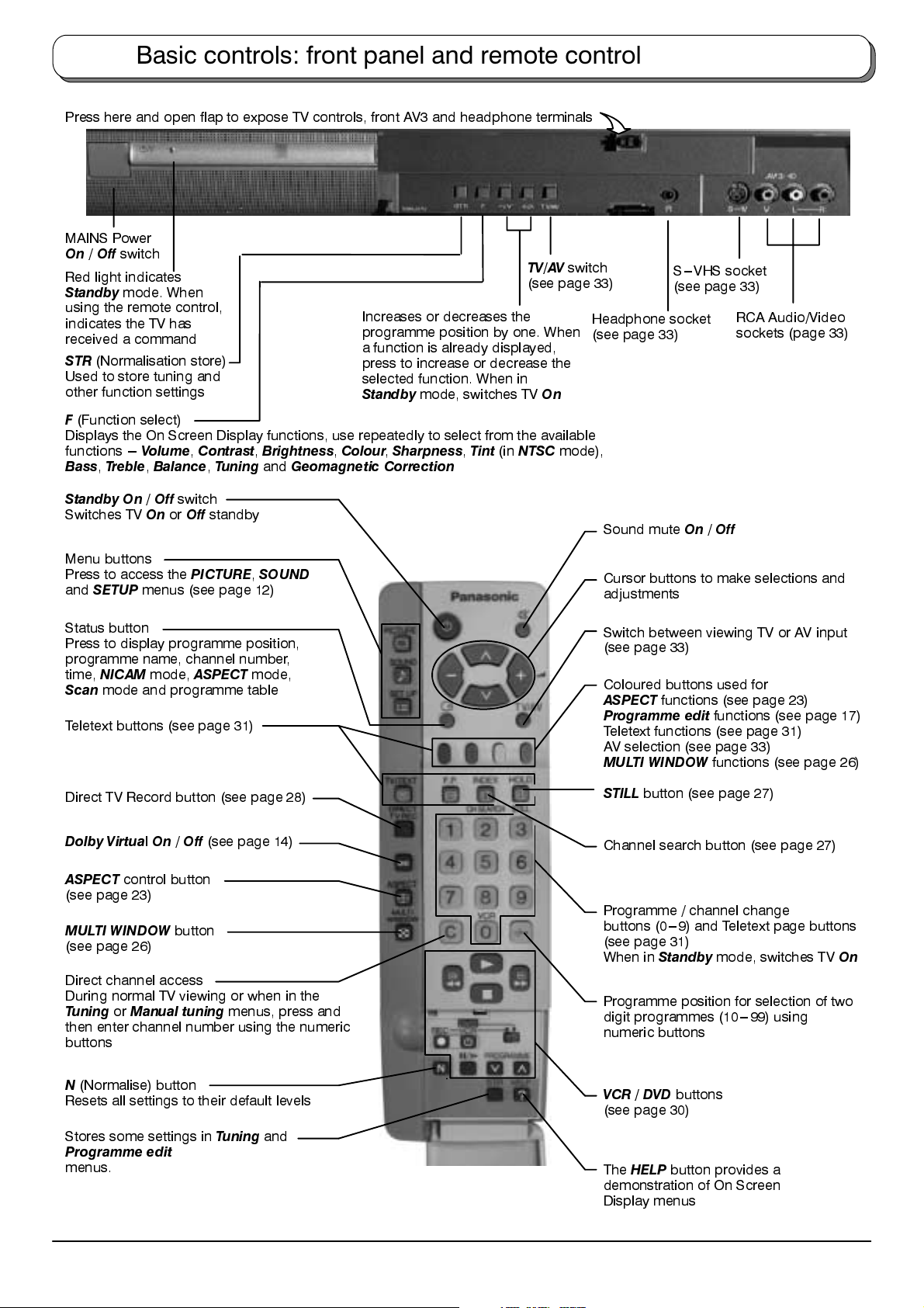
Basic controls: front panel and remote control
Press here and open flap to expose TV controls, front AV3 and headphone terminals
MAINS Power
On/Off
Red light indicates
Standby
using the remote control,
indicates the TV has
received a command
STR
Used to store tuning and
other function settings
F
Displays the On Screen Display functions, use repeatedly to select from the available
functions ---
Bass,Treble,Balance,Tuning
switch
mode. When
(Normalisation store)
(Function select)
Volume,Contrast,Brightness,Colour,Sharpness,Tint
Increases or decreases the
programme position by one. When
a function is already displayed,
press to increase or decrease the
selected function. When in
Standby
and
Geomagnetic Correction
mode, switches TV
(in
NTSC
TV/AV
switch
(see page 33)
On
mode),
S---VHS socket
(see page 33)
Headphone socket
(see page 33)
RCA Audio/Video
sockets (page 33)
Standby On/Off
Switches TVOnor
Menu buttons
Press to access the
and
SETUP
Status button
Press to display programme position,
programme name, channel number,
time,
NICAM
Scan
mode and programme table
Teletext buttons (see page 31)
Direct TV Record button (see page 28)
Dolby VirtualOn/Off
ASPECT
(see page 23)
MULTI WINDOW
(see page 26)
Direct channel access
During normal TV viewing or when in the
TuningorManual tuning
then enter channel number using the numeric
buttons
control button
switch
Off
standby
menus (see page 12)
PICTURE,SOUND
mode,
ASPECT
(see page 14)
button
mode,
menus, press and
Sound muteOn/
Cursor buttons to make selections and
adjustments
Switch between viewing TV or AV input
(see page 33)
Coloured buttons used for
ASPECT
Programme edit
Teletext functions (see page 31)
AV selection (see page 33)
MULTI WINDOW
STILL
Channel search button (see page 27)
Programme / channel change
buttons (0---9) and Teletext page buttons
(see page 31)
When in
Programme position for selection of two
digit programmes (10---99) using
numeric buttons
functions (see page 23)
button (see page 27)
Standby
Off
functions (see page 17)
functions (see page 26)
mode, switches TV
On
N
(Normalise) button
Resets all settings to their default levels
Stores some settings in
Programme edit
menus.
Tuning
and
VCR / DVD
(see page 30)
The
demonstration of On Screen
Display menus
buttons
HELP
button provides a
5
Quick Start Guide
Connection and setting up options
D
If connecting the TV using an RF cable only, see below.
D
If connecting the TV using Scart and RF cables, see page 6.
D
If connecting the TV to a Q--Link (or Q--Link compatible) VCR or DVD recorder, see page 7.
D
If connecting the TV to a Q--Link (or Q--Link compatible) VCR or DVD recorder and a satellite receiver, see page 8.
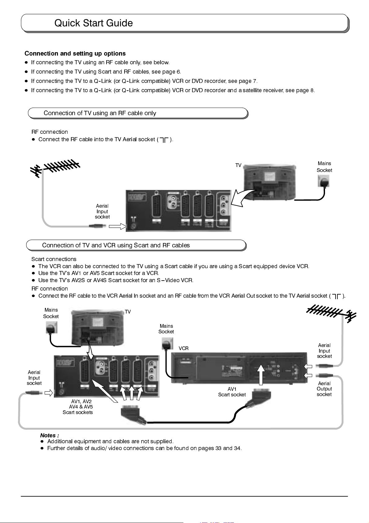
Connection of TV using an RF cable only
RF connection
D
Connect the RF cable into the TV Aerial socket (
).
TV
Aerial
Input
socket
Mains
Socket
Connection of TV and VCR using Scart and RF cables
Scart connections
D
The VCR can also be connected to the TV using a Scart cable if you are using a Scart equipped device VCR.
D
Use the TV’s AV1 or AV5 Scart socket for a VCR.
D
Use the TV’s AV2S or AV4S Scart socket for an S---Video VCR.
RF connection
D
Connect the RF cable to the VCR Aerial In socket and an RF cable from the VCR Aerial Out socket to the TV Aerial socket ( ).
Mains
Socket
TV
Mains
Socket
Aerial
Input
socket
6
VCR
Scart socket
AV1, AV2
AV4 & AV5
Scart sockets
Notes :
D
Additional equipment and cables are not supplied.
D
Further details of audio/ video connections can be found on pages 33 and 34.
AV1
Aerial
Input
socket
Aerial
Output
socket
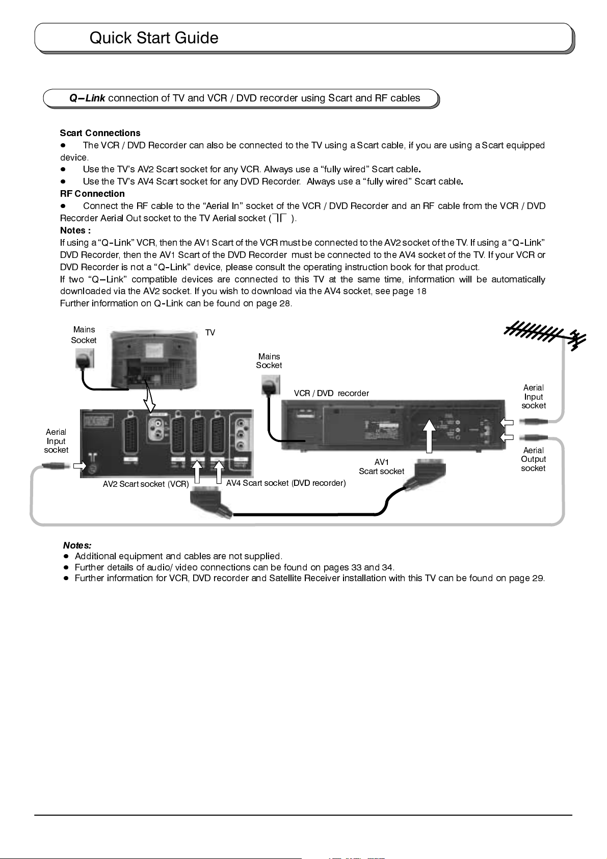
Quick Start Guide
Q --- L i nk
connection of TV and VCR / DVD recorder using Scart and RF cables
Scart Connections
D
The VCR / DVD Recorder can also be connected to the TV using a Scart cable, if you are using a Scart equipped
device.
D
Use the TV’s AV2 Scart socket for any VCR. Always use a “fully wired” Scart cable
D
Use the TV’s AV4 Scart socket for any DVD Recorder. Always use a “fully wired” Scart cable
.
.
RF Connection
D
Connect the RF cable to the “Aerial In” socket of the VCR / DVD Recorder and an RF cable from the VCR / DVD
Recorder Aerial Out socket to the TV Aerial socket ( ).
Notes :
If using a
“Q--Link”
VCR, then theAV1 Scart of the VCR mustbe connected to the AV2 socket of theTV. If using a
“Q--Link”
DVD Recorder, then the AV1 Scart of the DVD Recorder must be connected to the AV4 socket of the TV. If your VCR or
DVD Recorder is not a
“Q--Link”
device, please consult the operating instruction book for that product.
If two “Q---Link” compatible devices are connected to this TV at the same time, information will be automatically
downloaded via the AV2 socket. If you wish to download via the AV4 socket, see page 18
Further information on Q--Link can be found on page 28.
Mains
Socket
TV
Mains
Socket
VCR / DVD recorder
Aerial
Input
socket
Aerial
Input
socket
AV1
Scart socket
AV2 Scart socket (VCR)
AV4 Scart socket (DVD recorder)
Notes:
D
Additional equipment and cables are not supplied.
D
Further details of audio/ video connections can be found on pages 33 and 34.
D
Further information for VCR, DVD recorder and Satellite Receiver installation with this TV can be found on page 29.
Aerial
Output
socket
7
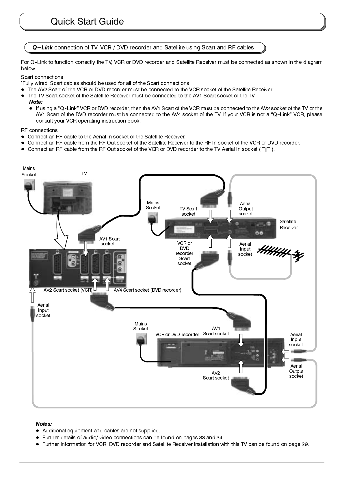
Quick Start Guide
Q --- L i nk
connection of TV, VCR / DVD recorder and Satellite using Scart and RF cables
For Q--Link to function correctly the TV, VCR or DVD recorder and Satellite Receiver must be connected as shown in the diagram
below.
Scart connections
’Fully wired’ Scart cables should be used for all of the Scart connections.
D
The AV2 Scart of the VCR or DVD recorder must be connected to the VCR socket of the Satellite Receiver.
D
The TV Scart socket of the Satellite Receiver must be connected to the AV1 Scart socket of the TV.
Note:
D
If using a
“Q--Link”
AV1 Scart of the DVD recorder must be connected to the AV4 socket of the TV. If your VCR is not a
VCR or DVD recorder, then the AV1 Scart of the VCR must be connected to the AV2 socket of the TV or the
“Q--Link”
VCR, please
consult your VCR operating instruction book.
RF connections
D
Connect an RF cable to the Aerial In socket of the Satellite Receiver.
D
Connect an RF cable from the RF Out socket of the Satellite Receiver to the RF In socket of the VCR or DVD recorder.
D
Connect an RF cable from the RF Out socket of the VCR or DVD recorder to the TV Aerial In socket (
Mains
Socket
TV
Mains
Socket
TV Scart
socket
Aerial
Output
socket
).
Satellite
Receiver
AV2 Scart socket (VCR)
Aerial
Input
socket
AV1 Scart
socket
AV4 Scart socket (DVD recorder)
Mains
Socket
VCR or
DVD
recorder
Scart
socket
VCR or DVD recorder
AV1
Scart socket
AV2
Scart socket
Aerial
Input
socket
Aerial
Input
socket
Aerial
Output
socket
Notes:
D
Additional equipment and cables are not supplied.
D
Further details of audio/ video connections can be found on pages 33 and 34.
D
Further information for VCR, DVD recorder and Satellite Receiver installation with this TV can be found on page 29.
8
Quick Start Guide
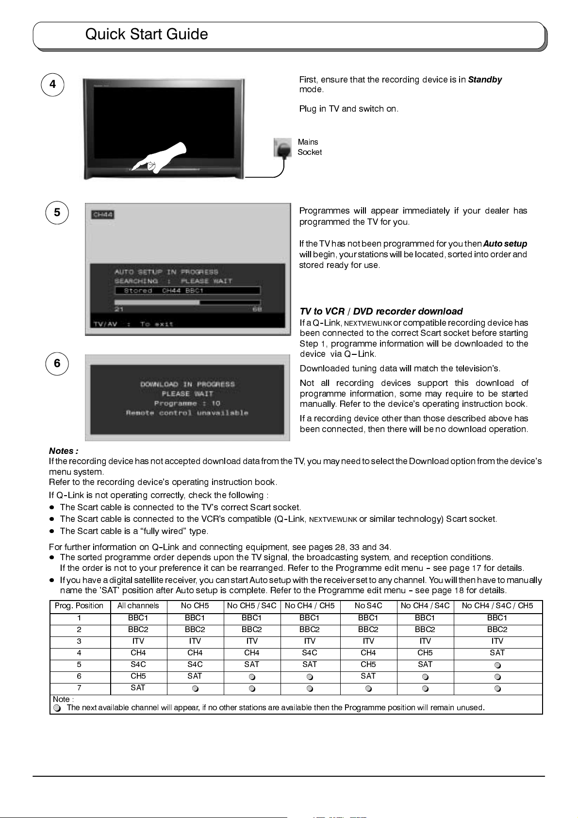
4
First, ensure that the recording device is in
mode.
Standby
Plug in TV and switch on.
Mains
Socket
5
Programmes will appear immediately if your dealer has
programmed the TV for you.
If the TVhas not beenprogrammed for youthen
Auto setup
willbegin,yourstationswill be located, sorted into order and
stored ready for use.
TV to VCR / DVD recorder download
IfaQ--Link,
been connected to the correct Scart socket before starting
Step 1, programme information will be downloaded to the
device via Q---Link.
6
Downloaded tuning data will match the television’s.
Not all recording devices support this download of
programme information, some may require to be started
manually. Refer to the device’s operating instruction book.
If a recording device other than those described above has
been connected, then there will be no download operation.
NEXTVIEWLINK
or compatible recording device has
Notes :
IftherecordingdevicehasnotaccepteddownloaddatafromtheTV, you may need to select theDownload option from the device’s
menu system.
Refer to the recording device’s operating instruction book.
If Q--Link is not operating correctly, check the following :
D
The Scart cable is connected to the TV’s correct Scart socket.
D
The Scart cable is connected to the VCR’s compatible (Q--Link,
D
The Scart cable is a “fully wired” type.
NEXTVIEWLINK
or similar technology) Scart socket.
For further information on Q--Link and connecting equipment, see pages 28, 33 and 34.
D
The sorted programme order depends upon the TV signal, the broadcasting system, and reception conditions.
If the order is not to your preference it can be rearranged. Refer to the Programme edit menu--see page 17 for details.
D
If you have a digital satellite receiver, youcan start Autosetup with thereceiver set to anychannel. Youwill then have to manually
name the ’SAT’ position after Auto setup is complete. Refer to the Programme edit menu--see page 18 for details.
Prog. Position All channels No CH5 No CH5 / S4C No CH4 / CH5 No S4C No CH4 / S4C No CH4 / S4C / CH5
1 BBC1 BBC1 BBC1 BBC1 BBC1 BBC1 BBC1
2 BBC2 BBC2 BBC2 BBC2 BBC2 BBC2 BBC2
3 ITV ITV ITV ITV ITV ITV ITV
4 CH4 CH4 CH4 S4C CH4 CH5 SAT
5 S4C S4C SAT SAT CH5 SAT
6 CH5 SAT
7 SAT
Note :
~
The next available channel will appear, if no other stations are available then the Programme position will remain unused.
~ ~ ~ ~ ~ ~
~ ~
SAT
~ ~
~
9
Quick Start Guide
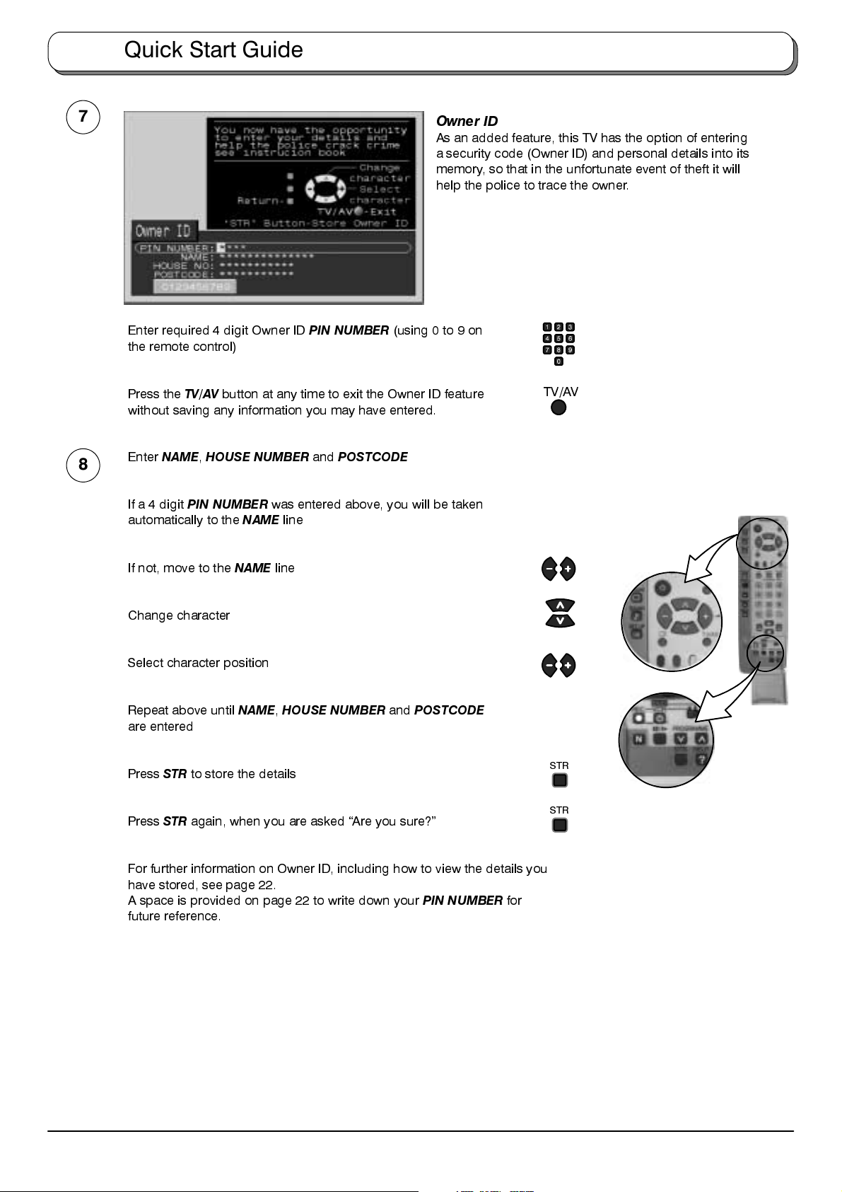
7
Enter required 4 digit Owner ID
the remote control)
Press the
without saving any information you may have entered.
8
Enter
If a 4 digit
automatically to the
TV/AV
button at any time to exit the Owner ID feature
NAME,HOUSE NUMBER
PIN NUMBER
NAME
PIN NUMBER
and
POSTCODE
was entered above, you will be taken
line
(using 0 to 9 on
Owner ID
As an added feature, this TV has the option of entering
a security code (Owner ID) and personal details into its
memory, so that in the unfortunate event of theft it will
help the police to trace the owner.
TV/AV
If not, move to the
Change character
Select character position
Repeat above until
are entered
Press
STR
to store the details
Press
STR
again, when you are asked “Are you sure?”
For further information on Owner ID, including how to view the details you
have stored, see page 22.
A space is provided on page 22 to write down your
future reference.
NAME
line
NAME,HOUSE NUMBER
and
POSTCODE
PIN NUMBER
for
STR
STR
10
Quick Start Guide
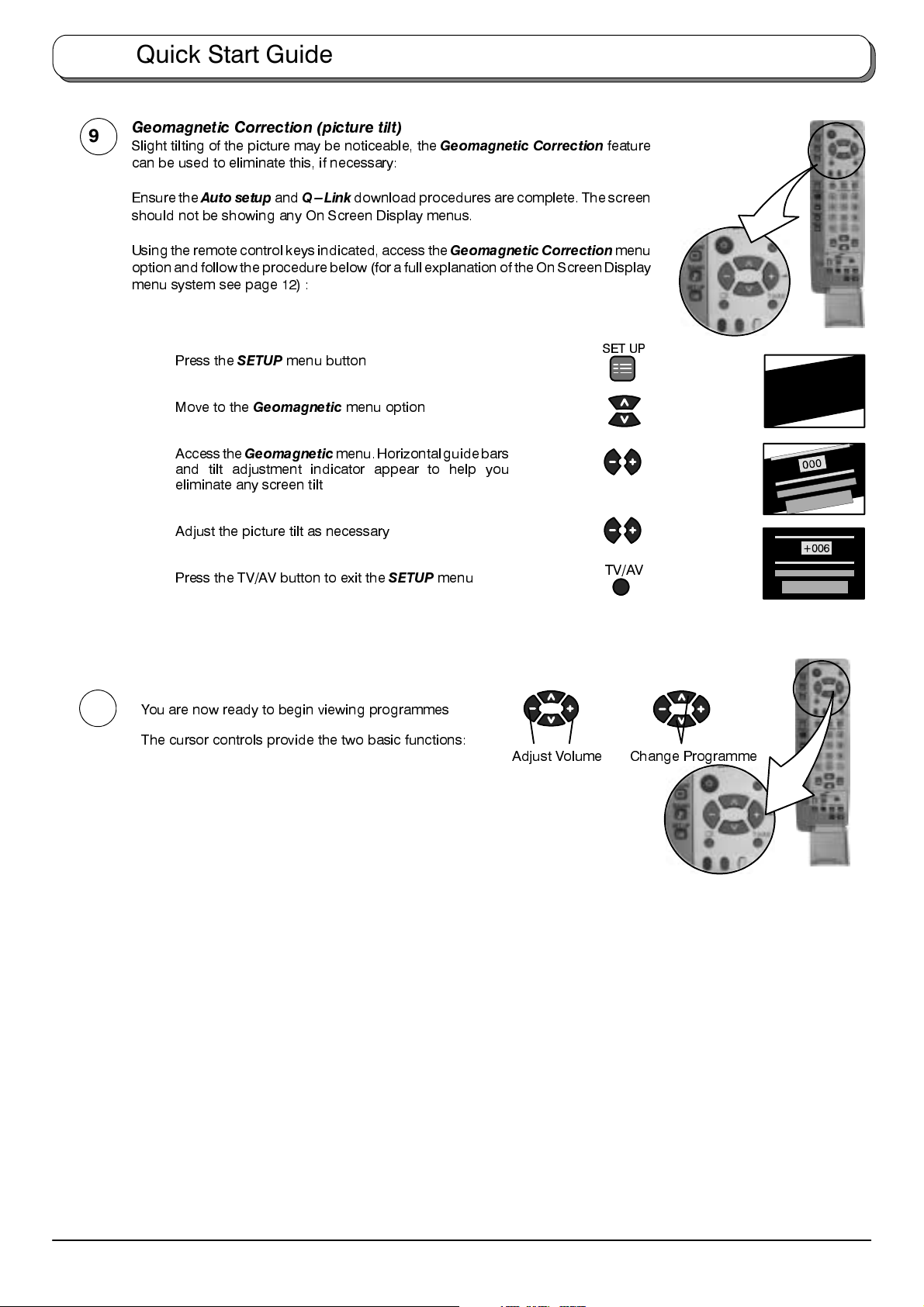
Geomagnetic Correction (picture tilt)
9
Slight tilting of the picture may be noticeable, the
can be used to eliminate this, if necessary:
Geomagnetic Correction
feature
Ensure the
should not be showing any On Screen Display menus.
Using the remotecontrol keys indicated, access the
option and follow the procedure below (for a full explanation of the On Screen Display
menu system see page 12) :
Auto setup
Press the
Move to the
Accessthe
and tilt adjustment indicator appear to help you
eliminate any screen tilt
Adjust the picture tilt as necessary
Press the TV/AV button to exit the
and
Q---Link
SETUP
menu button
Geomagnetic
Geomagnetic
download procedures are complete. The screen
Geomagnetic Correction
menu option
menu.Horizontalguidebars
SETUP
menu
menu
SET UP
TV/AV
10
You are now ready to begin viewing programmes
The cursor controls provide the two basic functions:
Adjust Volume Change Programme
11
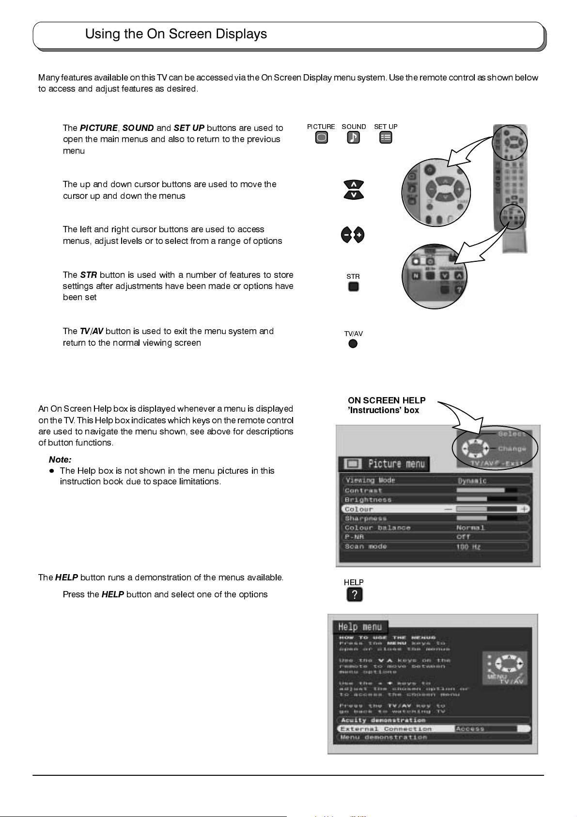
Using the On Screen Displays
Many features available on this TV canbe accessed viathe On ScreenDisplay menu system.Use the remotecontrol as shownbelow
to access and adjust features as desired.
The
PICTURE,SOUND
open the main menus and also to return to the previous
menu
The up and down cursor buttons are used to move the
cursor up and down the menus
The left and right cursor buttons are used to access
menus, adjust levels or to select from a range of options
The
STR
button is used with a number of features to store
settings after adjustments have been made or options have
been set
The
TV/AV
button is used to exit the menu system and
return to the normal viewing screen
An On ScreenHelp box is displayed whenever a menu isdisplayed
on the TV. This Helpbox indicates which keyson theremote control
are used to navigate the menu shown, see above for descriptions
of button functions.
and
SET UP
buttons are used to
PICTURE
SOUND
TV/AV
SET UP
STR
ON SCREEN HELP
’Instructions’ box
Note:
D
The Help box is not shown in the menu pictures in this
instruction book due to space limitations.
The
HELP
button runs a demonstration of the menus available.
Press the
HELP
button and select one of the options
HELP
?
12
 Loading...