

Page 1

ORDER No. PCZ0504048C2
Service Manual
Colour Television
TX-29PN1D, TX-29PN1F,
TX-29PN1P,
TX-28PN1D, TX-28PN1F,
TX-28PN1P,
GP4L Chassis
SPECIFICATIONS
(Information in brackets [ ] refers to models 28”)
Power Source: 220-240V a.c., 50Hz
Power Consumption: 68W [65W]
Stand-by Power
Consumption: 1W
Aerial Impedance: 75Ω unbalanced, Coaxial Type
Receiving System: PAL-I, B/G, D/K, PAL-525/60
SECAM B/G, D/K, L/L’
M.NTSC (AV only)
NTSC (AV only)
Receiving Channels:
VHF E2-E12 VHF H1-H2 (ITALY)
VHF A-H (ITALY) VHF R1-R2
VHF R3-R5 VHF R6-R12
UHF E21-E69 CATV (S01-S05)
CATV S1-S10 (M1-M10) CATV S11-S20 (U1-U10)
CATV S21-S41 (HYPERBAND)
Intermediate Frequency:
Video/Audio
Video 38,9MHz, 33,9MHz
Sound 33,4MHz (B/G), 33,16MHz (A2)
33,05MHz (NICAM B/G,D/K,L)
32,4MHz (D/K),32,66MHz (CZ STEREO)
40,4MHz (L’), 39,75MHz (L’NICAM)
Colour 34,47MHz (PAL)
34,5MHz, 34,65MHz (SECAM)
38,3MHz, 38,15MHz (SECAM L’)
AV2 IN Video (21 pin) 1V p-p 75Ω
Audio (21 pin) 500mV rms 10kΩ
S-Video IN Y: 1V p-p 75Ω
(21-pin) C:0,3V p-p 75Ω
AV2 OUT Video (21 pin) 1V p-p 75Ω
Audio (21 pin) 500mV rms 1kΩ
AV3 IN Audio (RCAx2) 500mV rms 10kΩ
Video (RCAx1) 1V p-p 75Ω
High Voltage: 31kV ± 1kV
Picture Tube: A68EPD10X30 68cm
[W66MAF185X03 66cm]
Audio Output: 2x5W RMS, 2x10W MPO,
8Ω impedance
Headphones: 8Ω Impedance
Accessories
supplied : Remote Control
2 x R6 (UM3) Batteries
Dimensions:
Height: 584mm [528mm]
Width: 668mm [698mm]
Depth: 500mm [490mm]
Net weight: 40kg [35,5kg]
Terminals:
AV1 IN Video (21 pin) 1V p-p 75Ω
Audio (21 pin) 500mV rms 10kΩ
RGB (21 pin) 0,7V p-p 75Ω
AV1 OUT Video (21 pin) 1V p-p 75Ω
Audio (21 pin) 500mV rms 1kΩ
Note:
Specifications are subject to change without notice.
Weights and dimensions shown are approximate.
Page 2
CONTENTS
SAFETY PRECAUTIONS ......................................................................................................................................................... 2
SERVICE HINTS ...................................................................................................................................................................... 3
ADJUSTMENT PROCEDURE AND SELF-CHECK.................................................................................................................. 4
WAVEFORM PATTERN TABLE............................................................................................................................................... 5
ALIGNMENT SETTINGS .......................................................................................................................................................... 6
BLOCK DIAGRAMS.................................................................................................................................................................. 7
PARTS LOCATION................................................................................................................................................................. 10
REPLACEMENT PARTS LIST................................................................................................................................................ 11
SCHEMATIC DIAGRAMS....................................................................................................................................................... 19
CONDUCTOR VIEWS ............................................................................................................................................................ 22
SAFETY PRECAUTION
GENERAL GUIDE LINES
1. It is advisable to insert an isolation transformer in the
a.c. supply before servicing a hot chassis.
2. When servicing, observe the original lead dress in the
high voltage circuits. If a short circuit is found, replace
all parts that have been overheated or damaged by
the short circuit.
3. After servicing, see that all the protective devices
such as insulation barriers, insulation papers, shields
and isolation R-C combinations are correctly
installed.
4. When the receiver is not being used for a long period
of time, unplug the power cord from the a.c. outlet.
5. Potentials as high as 32kV are present when this
receiver is in operation. Operation of the receiver
without the rear cover involves the danger of a shock
hazard from the receiver power supply. Servicing
should not be attempted by anyone who is not
familiar with the precautions necessary when working
on high voltage equipment. Always discharge the
anode of the tube.
6. After servicing make the following leakage current
checks to prevent the customer from being exposed
to shock hazard.
LEAKAGE CURRENT COLD CHECK
1. Unplug the a.c. cord and connect a jumper between
the two prongs of the plug.
2. Turn on the receiver’s power switch.
3. Measure the resistance value with an ohmmeter,
between the jumpered a.c. plug and each exposed
metallic cabinet part on the receiver, such as screw
heads, aerials, connectors, control shafts etc. When
the exposed metallic part has a return path to the
chassis, the reading should be between 4M ohm and
20M ohm. When the exposed metal does not have a
return path to the chassis, the reading must be
infinite.
LEAKAGE CURRENT HOT CHECK
1. Plug the a.c. cord directly into the a.c. outlet. Do not
use an isolation transformer for this check.
2. Connect a 2kΩ 10W resistor in series with an
exposed metallic part on the receiver and an earth,
such as a water pipe.
3. Use an a.c. voltmeter with high impedance to
measure the potential across the resistor.
4. Check each exposed metallic part and check the
voltage at each point.
5. Reverse the a.c. plug at the outlet and repeat each of
the previous measurements.
6. The potential at any point should not exceed
1,4 Vrms. In case a measurement is outside the limits
specified, there is a possibility of a shock hazard, and
the receiver should be repaired and rechecked before
it is returned to the customer.
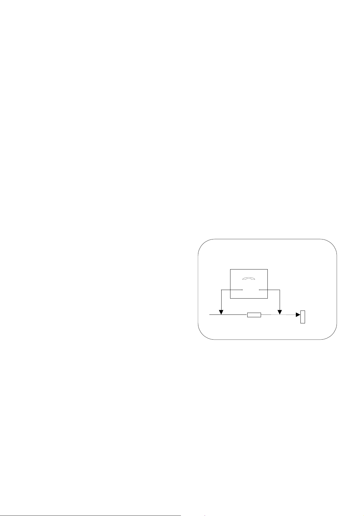
HOT CHECK CIRCUIT
a.c. VOLTMETER
2kΩ 10 Watts
TO INSTRUMENT'S EXPOSED
METALLIC PARTS
Fig. 1.
X-RADIATION WARNING
1. The potential sources of X-Radiation in TV sets are
the high voltage section and the picture tube.
2. When using a picture tube test jig for service, ensure
that the jig is capable of handling 32kV without
causing X-Radiation.
NOTE: It is important to use an accurate periodically
calibrated high voltage meter.
1. Set the brightness to minimum.
2. Measure the high voltage. The meter should indicate:
31kV ± 1kV.
If the meter indication is out of tolerance, immediate
service and correction is required to prevent the
possibility of premature component failure.
3. To prevent any X-Radiation possibility, it is essential
to use the specified tube.
WATER PIPE
(
EARTH)
2
Page 3

SERVICE HINTS
How to remove the rear cover
1. Remove the 10 screws as shown in Fig.2.
SCREWS
LOCATION OF CONTROLS
SCREWS
Fig. 2
L-Board
D-Board
Focus
Fig.3
3
Screen
Page 4

A
A
ADJUSTMENT PROCEDURE
Item / Preparation Adjustments
+B SET-UP
1. Receive a Window pattern.
2. Set the controls :
Brightness Minimum
Contrast Minimum
Volume Minimum
Confirm the following voltages:
TPD11 12,3 ± 0,5V TPD21 9,4 ± 0,5V
TPD12 3,3 ± 0,15V TPD23 138 ± 1,5V
TPD13 5 ± 0,25V TPD121 205 ± 10V
TPD16 8 ± 0,3V TPD122 17,2 ± 1V
TPD17 3,3 ± 0,15V TPD123 -11,6 ± 1V
TPD20 1,8 ± 0,1V TPD124 13,6 ± 1V
TPL5 6,3 ± 0,3V
Audio 5W
13,5 ± 0,5V 5,7 ± 0,3V
Audio MIN
Normal mode
Standby mode
CUT OFF / Ug2 Test
1. Receive a Window pattern.
3. Set:
Colour 50%
Brightness 50%
Contrast 100%
To adjust Cutoff connect an oscilloscope to the Blue cathode. Adjust
the screen VR until the black level is 160V ± 2V.
Black Level
160V ± 2V
GND
SELF CHECK
Self-check is used to automatically check the bus lines and hexadecimal code of the TV set.To enter Self-Check mode, press
the STATUS button on the remote control and at the same time press the down (-/v) button on the customer controls at
the front the TV set. To exit Self Check, switch off the TV set at the power button.
E2 O.K. TUN O.K.
DDP O.K. MSP O.K.
VSP O.K. DPL ---
VSW O.K. MAS ---
VCTi F1
TX-29PN1D
OPTION 1 0F
OPTION 2 00
OPTION 3 A0
OPTION 4 11
OPTION 5 00
OPTION 6 35
OPTION 7 7F
OPTION 8 D4
OPTION 9 00
OPTION 10 00
OPTION 11 11
OPTION 12 00
OPTION 13 88
CHECK E1
TX-29PN1F
TX-29PN1P
0F
00
0
11
00
35
7F
54
00
00
11
00
88
61
TX-28PN1D
0F
00
B0
11
00
35
7F
D4
00
00
11
00
88
F1
TX-28PN1F
TX-28PN1P
0F
00
B0
11
00
35
7F
54
00
00
11
00
88
71
If the CCU ports have been checked and found to be incorrect or not located then " - - " will appear in place of "O.K.".
4
Page 5
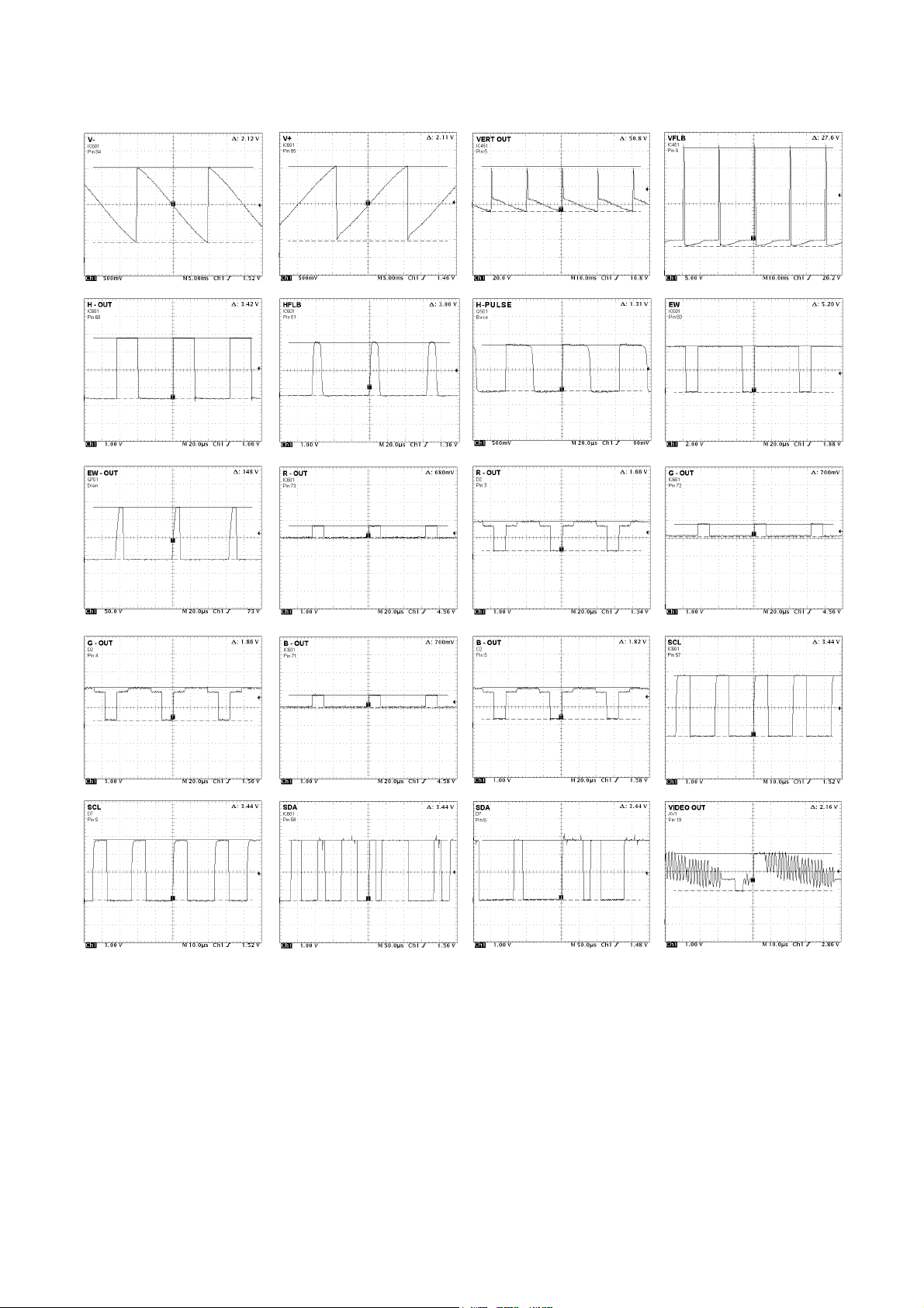
WAVEFORM PATTERN TABLE
CONDITIONS: Contrast: MAX, Brightness: MID, Colour: MID, Sharpness: MID
R,G,B /IC601/: Receive a window pattern.
5
Page 6

ALIGNMENT SETTINGS
(The figures below are nominal and used for representative purposes only.)
1. Set the Bass to maximum position, set the Treble to minimum position, set the Volume to minimum then press the
down button (-/v) on the customer controls at the front of the TV and at the same time press the INDEX button on the
remote control, this will place the TV into the Service Mode 1.
2. Press the RED / GREEN buttons to step up / down through the functions.
3. Press the YELLOW / BLUE buttons to alter the function values.
4. Press the OK button after each adjustment has been made to store the required values.
5. To exit the Service Mode, press the "N" button.
Alignment Function
EAROM copy TV/EXT ---
FLASH program copy EXT -> TV ---
Horizontal Position
Vertical Position
Horizontal Amplitude
Vert. Amplitude
EW-amplitude
Lower Corner
Trapezium-comp
Upper Corner
Note: All setting values are approximate
Setting indication
H-Pos
-4
V-Pos
0
H-Amp
93
V-Amp
-15
EW-Amp 1
- 30
Lower Corner
11
Trapez 1
4
Upper Corner
11
Settings / Special features
Optimum setting.
Optimum setting.
Optimum setting.
Optimum setting.
Optimum setting.
Optimum setting.
Optimum setting.
Optimum setting.
Vertical Linearity
Vertical Symmetry
Angle
Bow
DVCO
Highlight
Lowlight
Sub-Brightness
V-Lin
39
V-Sym
-6
Angle
0
Bow
0
DVCO
63
High 0374 0318 0335
Low 0207 0331 0256
Sub-Brightness
-10
Optimum setting.
Optimum setting.
Optimum setting.
Optimum setting.
Receive a PAL Colour Bar Pattern. For
DVCO alignment press "Blue" button, wait
until the figure colour is changed from red
to black colour.
Optimum setting.
Optimum setting.
6
Page 7

D353
D352
Q354
L2
D2
CRT
D5
R
3
1
L
2
4
R
L
V
Q353
Q352
Q351
R 9
B 7
G 8
3
2
1
IC351
67
1542 3
L-BOARD
5
3
3
R
6
4
4
5
6
B
G
4 R IN
2 L IN
IC2301
LA42072-E
UDIO OUTPUT
R OUT(1) 9
L OUT(1) 11
R OUT(0) 8
L OUT(0) 12
JK3201
2 R IN
6 L IN
1 R OUT
3 L OUT
R
L
HEADPH
FRONT AV3 TERMINAL
Q308
Q309
Q304 Q307
Q306
Q305
Q301
Q302
Q303
5 SPEAKR
4 SPEAKL
82 SENSE
71 BOUT
72 GOUT
73 ROUT
VIDEO & STEREO AUDIO & DEFLECTION BLOCK DIAGRAM
11
10
TUNER
AV2_IR 4
AV2_I L 11
UDIO SWITCH
IC2401
TC74HC4066AF
10 AV12_IL
AV12_IL 12
1 AV1_IR
3
2 AV12_IR
AV12_IR 13
16 IF1
17 IF2
XF101
9
AV2 21 PIN SCART
TC74HC4066AF
15 C_IN
19 VIDEO OUT
20 VIDEO IN
8 AV1_IL
AV2_OR 9
AV3_IR 11
AV3_V 38
AV3_IL 10
IC601
VCT4973FPZF1
MICROPROCESSOR
61 HFLB
60 H-OUT
Q501
85 V+
83 EW
AV2_OL 8
AV2_C 34
84 V-
59 VPROT
Q702
Q606
AV1_OR 7
AV1_OL 6
B_IN 30
AV2_OUT 41
AV2_CVBS 35
G_IN 31
R_IN 32
AV1_OUT 40
AV1_CVBS 33
VFLB
D601
Q701
Q703
T551
10
Q605
6
7
1
IC451
VERTICAL
6 L IN
2 R IN
1 R OUT
3 L OUT
7 B IN
11 G IN
15 R IN
19 VIDEO OUT
20 VIDEO IN
5
AV1 21 PIN SCART
13
4
D6
DEFLECTION
6
1
T553
D-BOARD
4
Q551
DIODE
MODULATOR
Page 8

8
,
r
5V
LED
,
,
D - BOARD
7
9
TUNER
33V
R003
142V
R890
D890
D891
T553
3
MUTE
8V
3V SBY
3
Q2102 Q2101
8V
Q880
2
REG
IC850
1
15V
3V
3
10,5V
Q850
1
D852
IC870
3,3V_SBY
REG
1,8V_SBY
5
3
2
REG
IC860
1
3,3V_SBY
IC451
VERTICAL
2,6
4
13,6V
17,2V
-11,6V
D513
D515
D516
POWER BUS
9
T551
1
D552
7
2
8
RS
VCC
RM1062
5
IC2301
7
AUDIO OUTPUT
14
IC2401
AUDIO SWITCH
3,3V_SBY
5V
15V
8V
IC1103
IC603
IC601
3,3V_SBY
8
EAROM
3,3V_SBY
2
RESET
142V
3,3V_SBY
46,65
1,8V_SBY
24,43
3,3V
VCT4973FPZF1
21,64,68
5V_DEF
19,20,87
8V
2
T801
D841
D840
S2
S3
S6
P1
P2
D842
2
Q893
D892
D843
R870
D854
D853
1
REG
IC840
2
PC841
6
3
1
POWER
SUPPLY
IC801
D3
L3
205V
1
1
D2
L2
8V
1
1
3,3V_SBY
D7
SERVICE
2
350V
+
4
R825
6
L - BOARD
IC351
POWER SUPPLY BLOCK DIAGRAM
RGB OUTPUT
Q354
Used only
D803
for 29“ models
T804
5V
10
LF832
5
4
Line
R801
8
1
Filte
RL801
R822 R823
Q895
SW840
F840
1
D8
Mains In
4
1
D9
Degauss
2
coil
Page 9

SERVICE/TEST
6
5
7
RM
8
KEYSCAN
IC2301
LA42072-E
6 MUTE
POWER SUPPLY
D7
SDA
SCL
TUNER
4 SCL
1 AGC
5 SDA
Q861
5
SDA
SCL 6
EAROM
IC1103
14
AGC
7
L
SDA 58
ST/ON 50
CONTROL BLOCK DIAGRAM
47 LED
51 KEYSCAN
D2108
8 SLOW2
AV2 21 PIN SCART
D601
Q2102
49
FBIN 29
VPROT 59
VCT_MUTE
REG_ON_OFF 27
IC601
VTC4973FPZF1
MICROPROCESSOR
RESET 18
52 SLOW 1
56 RM
55 DEGAUSS
53 SLOW 2
5
1 VOUT
IC850
PQ1CG21H2RZH
RESET
IC603
16 FBIN
Q1062
Q603
RM
LED
D1061
D - BOARD
LOCAL KEYS
MATRIX
SWITCHING
REMOTE
RM1062
Q895
RL801
8 SLOW1
AV1 21 PIN SCART
9
Page 10

PARTS LOCATION
NOTE:
The numbers on the exploded view below
refer to the exploded view section of the
Replacement Parts List.
11
17
12
2
9
13
19
14
10
7
18
16
4
5
6
15
3
1
8
10
Page 11

Components Identified by mark have special characteristics important for safety.
* When replacing any of these components, use only manufacturers specified parts.
In case of ordering these spare parts, please always add the complete Model-Type
number to your order.
DescriptionCct Ref Parts Number DescriptionCct Ref Parts Number
COMMON PARTS
EXPLODED VIEW
SPEAKER 1 EASG12D552A2
TUNER 2 ENV57K01G3F
REMOTE CONTROL 3 EUR7651010
PANASONIC BADGE 4 TBM0E3002
POWER BUTTON 5 TBX0E81100
5-KEY BUTTON 6 TBX0E81200
CRT FIXING SCREW 7 THT1062J
AV COVER 8 TKP0E12701
CHASSIS RAIL 9 TMZ0E9803
L P.C.B. 10 TNP0EL006AA
FOCUS LEAD ASSY 11 TXJ/FC0DEG1
F.B.T.+ ANODE ASSY 12 ZTFP14501A
MISCELLANEOUS COMPONENTS
BATTERY .R6RC/2P
CRT EARTH SPRING . TES2298
IR WINDOW . TKP0E12601
LED HOLDER . TMW0E704-1
I.C.s
RGB OUTPUT IC351 TDA6108JF
VERTICAL OUTPUT IC451 LA78045-E
MICRO VCT4973FPZF1IC601 GP4L/SW1.03
IC RESET IC603 XC61CN2802TH
POWER SUPPLY IC801 STRW6754LF06
ERROR AMPLIFIER IC840 SE130N
REGULATOR IC850 PQ1CG21H2RZH
REGULATOR IC860 PQ1CG21H2RZH
REGULATOR IC870 C0CBABD00059
AUDIO AMPLIFIER IC2301 LA42072-E
AUDIO SWITCH IC2401 C0JBAS000227
LED RECEIVER RM1062 KSM-602LM2EL
FUSES
FUSE F840 K5D502BNA005
FS LINK F841 TSF19632
DIODES
THERMISTOR CF830 59890T60B110
DIODE D351 1N4148-34
DIODE D352 1N4148-34
DIODE D353 1N4148-34
DIODE D354 1N4148-34
DIODE D357 1N4148-34
DIODE D358 1N4148-34
DIODE D359 1N4148-34
REPLACEMENT PARTS LIST
Important Safety Notice
DIODE D360 EU02
DIODE D361 EU02
DIODE D362 EU02
DIODE D402 1SR124-4AT82
DIODE D501 1SR124-4AT82
DIODE D506 1SR124-4AT82
DIODE D507 1N4148-34
DIODE D512 1N4148-34
DIODE D513 1SR124-4AT82
DIODE D515 1SR124-4AT82
DIODE D516 1SR124-4AT82
DIODE D552 1SR124-4AT82
DIODE D556 FMQ-G2FLS699
DIODE D557 RU3LFA1
DIODE D558 1N4148-34
DIODE D561 1N4148-34
DIODE D562 1N4148-34
DIODE D580 MA4130MTA
DIODE D601 DAN217T146
DIODE D604 1N4148WS
DIODE D708 1SR124-4AT82
DIODE D801 EU02
DIODE D802 EU02
DIODE D803 RS406MBSR01
DIODE D810 SARS01LF-F7
DIODE D817 1SR124-4AT82
DIODE D820 MAZ20820A0LS
DIODE D823 1N4148-34
DIODE D824 1N4148-34
DIODE D825 GDZJ6.8C-34
DIODE D840 RU4AMLF-M1
DIODE D841 RU3LFA1
DIODE D842 RU4BLF-L1
DIODE D843 AU02AV0
DIODE D844 1N4148WS
DIODE D845 GDZJ3.3A-34
DIODE D846 1SR124-4AT82
DIODE D847 1N4148-34
DIODE D849 GDZJ3.6A-34
DIODE SFPB-74V D850 B0JCNE000004
DIODE D851 B0HCMM000014
DIODE D852 GDZJ6.8C-34
DIODE D853 MTZJT-777.5B
DIODED854 MA165TA5
DIODE SFPB-74V D860 B0JCNE000004
DIODE D861 B0HCMM000014
DIODE D862 GDZJ20C-34
DIODE D880 GDZJ8.2B-34
DIODE D881 1N4148WS
DIODE D890 MTZJT-7716A
DIODE D891 MTZJT-7716A
11
Page 12

TRANSISTORS
TRANSFORMERS
COILS
DescriptionCct Ref Parts Number DescriptionCct Ref Parts Number
DIODE D892 BT149D
DIODE D895 GDZJ5.1B-34
DIODE D896 1N4148WS
DIODE D897 1N4148-34
DIODE D1056 GDZJ3.6A-34
LED D1061 LS5469-GK
DIODE D1132 GDZJ3.9A-34
DIODE D2103 1N4148-34
DIODE D2107 1N4148-34
DIODE D2108 1N4148-34
DIODE D3141 GDZJ8.2C-34
DIODE D3142 GDZJ8.2C-34
DIODE D3143 1N4148-34
DIODE D3144 1N4148-34
PHOTO COUPLER PC841 SFH617A-20P6
TRANSISTOR Q301 BC847B
TRANSISTOR Q302 BC847B
TRANSISTOR Q303 BC847B
TRANSISTOR Q304 BC847B
TRANSISTOR Q305 BC847B
TRANSISTOR Q306 BC847B
TRANSISTOR Q307 BC857B
TRANSISTOR Q308 BC857B
TRANSISTOR Q309 BC857B
TRANSISTOR Q351 2SA1767
TRANSISTOR Q352 2SA1767
TRANSISTOR Q353 2SA1767
TRANSISTOR Q354 BC857B
TRANSISTOR Q501 2SD2195T100
TRANSISTOR Q551 2SC5517000LK
TRANSISTOR Q581 BC857B
TRANSISTOR Q603 BC847B
TRANSISTOR Q605 BC847B
TRANSISTOR Q606 BC847B
TRANSISTOR Q610 BC857B
TRANSISTOR Q611 BC857B
TRANSISTOR Q701 2SK3342TE16Q
TRANSISTOR Q702 MMBT3904
TRANSISTOR Q703 MMBT3904
TRANSISTOR Q841A BC847B
TRANSISTOR Q850 2SC1318-S
TRANSISTOR Q861 BC847B
TRANSISTOR Q880 BC547B/126
TRANSISTOR Q881 BC847B
TRANSISTOR Q882 BC857B
TRANSISTOR Q893 BC847B
TRANSISTOR Q895 BC847B
TRANSISTOR Q1062 BC847B
TRANSISTOR Q2101 BC857B
TRANSISTOR Q2102 BC847B
TRANSISTOR Q2402 BC847B
TRANSISTOR Q2403 BC847B
TRANSFORMER T553 ETH19Y209AZ
TRANSFORMER T801 ETS35AA6X6AC
COIL L002 TALV35VB100K
COIL L004 TALV35VB100K
COILL005 EXCELSA35T
COIL L108 ELJFAR68KF2
COILL300 EXCELDR35V
COIL L301 TLTACT4R7K
COIL L553 ELC16B821L
COIL L555 ELC10D821E
FILTERS
CRYSTALS
RESISTORS
COIL L556 ELC08D682E
COIL L601 G0C100JA0055
COIL L602 G0C100JA0055
COIL L603 G0C100JA0055
COIL L604 G0C100JA0055
COILL605 EXCELDR35V
COIL L606 G0C100JA0055
COILL607 EXCELDR25V
COIL L608 G0C100JA0055
COIL L609 G0C100JA0055
COILL610 EXCELSA35T
COIL L611 G0C100JA0055
COIL L613 EXCELSA35V
COIL L614 EXCELSA35V
COILL615 EXCELDR25V
COILL616 EXCELSA35T
COIL L617 EXCELSA35V
COIL L623 EXCELSA35V
COIL L625 EXCELSA35V
COILL820 EXCELSA39V
COILL841 EXCELSA35T
COILL842 EXCELSA35T
COILL844 EXCELSA39V
COILL845 EXCELSA39V
COILL846 EXCELSA35B
COIL L847 TSL0808S470K
COIL L850 G0A471ZA0041
COIL L860 G0A471ZA0041
COIL L861 TLTACT4R7K
COIL L1061 TLT331K991R
COILL2301 EXCELSA35T
COILL2302 EXCELSA35T
COIL L2303 ELJFC100KF
COILL2313 EXCELDR35V
COILL2314 EXCELDR35V
COIL L2321 EXC3BB221H
COIL L2322 EXC3BB221H
COILL2323 EXCELDR35V
COILL2324 EXCELDR35V
COILL2325 EXCELDR35V
COILL2326 EXCELDR35V
COILL2327 EXCELDR35V
COIL L3000 TLTACT2R2K
COIL L3001 TLTACT2R2K
COIL L3002 ELJFC4R7KF
COIL L3003 ELJFC4R7KF
COIL L3004 ELJFC2R2KF
COIL L3005 ELJFC2R2KF
COIL L3006 TLTACT4R7K
COIL L3007 TLTACT4R7K
COIL L3142 SPT0305A6R8K
COIL L3143 SPT0305A6R8K
LINE FILTER LF832 ELF18N012A
FILTER XF101 F4SE-H0E5
CRYSTAL X601 4730007267
S.M.CARBJA4 ERJ6GEY0R00 0.1W - 0 Ω
S.M.CARBJA5 ERJ6GEY0R00 0.1W - 0 Ω
S.M.CARBJA6 ERJ6GEY0R00 0.1W - 0 Ω
S.M.CARBJA8 ERJ6GEY0R00 0.1W - 0 Ω
S.M.CARBJA9 ERJ6GEY0R00 0.1W - 0 Ω
S.M.CARBJA10 ERJ6GEY0R00 0.1W - 0 Ω
S.M.CARBJA11 ERJ6GEY0R00 0.1W - 0 Ω
12
Page 13

DescriptionCct Ref Parts Number DescriptionCct Ref Parts Number
S.M.CARBJA12 ERJ6GEY0R00 0.1W - 0 Ω
S.M.CARBJA13 ERJ6GEY0R00 0.1W - 0 Ω
S.M.CARBJA14 ERJ6GEY0R00 0.1W - 0 Ω
S.M.CARBJA15 ERJ6GEY0R00 0.1W - 0 Ω
S.M.CARBJA17 ERJ6GEY0R00 0.1W - 0 Ω
S.M.CARBJA18 ERJ6GEY0R00 0.1W - 0 Ω
S.M.CARBJA19 ERJ6GEY0R00 0.1W - 0 Ω
S.M.CARBJA20 ERJ6GEY0R00 0.1W - 0 Ω
S.M.CARBJA21 ERJ6GEY0R00 0.1W - 0 Ω
S.M.CARBJSD501 ERJ6GEY0R00 0.1W - 0 Ω
S.M.CARBJSD608 ERJ6GEY0R00 0.1W - 0 Ω
S.M.CARBJSD669 ERJ8GEY0R00 .125W - 0 Ω
S.M.CARBJSD670 ERJ8GEY0R00 .125W - 0 Ω
S.M.CARBJSD671 ERJ6GEY0R00 0.1W - 0 Ω
S.M.CARBJSD672 ERJ6GEY0R00 0.1W - 0 Ω
S.M.CARBJSD674 ERJ6GEY0R00 0.1W - 0 Ω
S.M.CARBJSD675 ERJ6GEY0R00 0.1W - 0 Ω
S.M.CARBJSD676 ERJ6GEY0R00 0.1W - 0 Ω
S.M.CARBJSD2312 ERJ6GEY0R00 0.1W - 0 Ω
S.M.CARBJSD3132 ERJ6GEY0R00 0.1W - 0 Ω
S.M.CARBJSD3133 ERJ6GEY0R00 0.1W - 0 Ω
S.M.CARBL003 ERJ6GEY0R00 0.1W - 0 Ω
S.M.CARBR001 ERJ6GEYJ220 0.1W 5% 22 Ω
S.M.CARBR002 ERJ6GEYJ220 0.1W 5% 22 Ω
S.M.CARBR003 ERJ6GEYJ103 0.1W 5% 10K Ω
S.M.CARBR005 ERJ6GEYJ512 0.1W 5% 5K1 Ω
S.M.CARBR006 ERJ6GEYJ473 0.1W 5% 47K Ω
S.M.CARBR007 ERJ6GEYJ682 0.1W 5% 6K8 Ω
S.M.CARBR253 ERJ6GEYJ103 0.1W 5% 10K Ω
S.M.CARBR255 ERJ6GEYJ103 0.1W 5% 10K Ω
S.M.CARBR256 ERJ6GEYJ101 0.1W 5% 100 Ω
S.M.CARBR257 ERJ6GEYJ101 0.1W 5% 100 Ω
S.M.CARBR301 ERJ6GEYJ103 0.1W 5% 10K Ω
S.M.CARBR302 ERJ6GEYJ103 0.1W 5% 10K Ω
S.M.CARBR303 ERJ6GEYJ103 0.1W 5% 10K Ω
S.M.CARBR304 ERJ6GEYJ240 0.1W 5% 24 Ω
S.M.CARBR305 ERJ6GEYJ240 0.1W 5% 24 Ω
S.M.CARBR306 ERJ6GEYJ240 0.1W 5% 24 Ω
S.M.CARBR307 ERJ6GEYJ681 0.1W 5% 680 Ω
S.M.CARBR308 ERJ6GEYJ681 0.1W 5% 680 Ω
S.M.CARBR309 ERJ6GEYJ681 0.1W 5% 680 Ω
SMDR310 ERJ8GEYJ221V 0.25W 5% 220 Ω
SMDR311 ERJ8GEYJ221V 0.25W 5% 220 Ω
SMDR312 ERJ8GEYJ221V 0.25W 5% 220 Ω
S.M.CARBR317 ERJ6GEYJ151 0.1W 5% 150 Ω
S.M.CARBR318 ERJ6GEYJ151 0.1W 5% 150 Ω
S.M.CARBR319 ERJ6GEYJ151 0.1W 5% 150 Ω
S.M.CARBR351 ERJ6GEYJ222 0.1W 5% 2K2 Ω
S.M.CARBR352 ERJ6GEY0R00 0.1W - 0 Ω
S.M.CARBR353 ERJ6GEYJ331 0.1W 5% 330 Ω
S.M.CARBR354 ERJ6GEYJ331 0.1W 5% 330 Ω
S.M.CARBR355 ERJ6GEYJ331 0.1W 5% 330 Ω
S.M.CARBR356 ERJ6GEYJ331 0.1W 5% 330 Ω
S.M.CARBR357 ERJ6GEYJ220 0.1W 5% 22 Ω
FUSIBLE R360 ERQ12AJ121 0.5W 5% 120 Ω
CARBONR363 ERD25TJ102 0.25W 5% 1K Ω
CARBONR364 ERD25TJ102 0.25W 5% 1K Ω
CARBONR365 ERD25TJ102 0.25W 5% 1K Ω
CARBONR366 ERDS1TJ152 0.5W 5% 1K5 Ω
CARBONR367 ERDS1TJ152 0.5W 5% 1K5 Ω
CARBONR368 ERDS1TJ152 0.5W 5% 1K5 Ω
CARBONR374 ERD25TJ274 0.25W 5% 270K Ω
S.M.CARBR375 ERJ6GEYJ684 0.1W 5% 680K Ω
S.M.CARBR376 ERJ6GEYJ183 0.1W 5% 18K Ω
S.M.CARBR403 ERJ6GEYJ563 0.1W 5% 56K Ω
S.M.CARBR405 ERJ6GEYJ563 0.1W 5% 56K Ω
METALR406 ERX12SJR82P 0.5W 5% R82 Ω
METALR416 ERX2SJSR82H 2W 5% 0.82 Ω
S.M.CARBR451 ERJ6GEYJ223 0.1W 5% 22K Ω
S.M.CARBR453 ERJ6GEYJ103 0.1W 5% 10K Ω
METALR505 ERG1SJ222E 0.5W 5% 2K2 Ω
S.M.CARBR507 ERJ6GEYJ561 0.1W 5% 560 Ω
S.M.CARBR512 ERJ6ENF1001 0.1W 1% 1K Ω
S.M.CARBR513 ERJ6GEYJ680 0.1W 5% 68 Ω
METALR554 343-23R3AY 10W 5% 3R3 Ω
METALR557 ERG2SJ102E 2W 5% 1K Ω
FUSIBLER559 ERQ12HKR39P 0.5W 10% R39 Ω
S.M.CARBR561 ERJ6GEYJ183 0.1W 5% 18K Ω
S.M.CARBR562 ERJ6GEYJ472 0.1W 5% 4K7 Ω
S.M.CARBR563 ERJ6GEYJ103 0.1W 5% 10K Ω
S.M.CARBR564 ERJ6GEYJ273 0.1W 5% 27K Ω
S.M.CARBR565 ERJ6GEYJ272 0.1W 5% 2K7 Ω
S.M.CARBR566 ERJ6GEYJ303 0.1W 5% 30K Ω
S.M.CARBR567 ERJ6GEYJ273 0.1W 5% 27K Ω
S.M.CARBR568 ERJ6GEYJ822 0.1W 5% 8K2 Ω
S.M.CARBR569 ERJ6GEYJ153 0.1W 5% 15K Ω
SMDR580 ERJ6ENF2202 .125W 1% 22K Ω
S.M.CARBR592 ERJ6GEYJ103 0.1W 5% 10K Ω
S.M.CARBR593 ERJ6GEYJ103 0.1W 5% 10K Ω
S.M.CARBR594 ERJ6GEYJ332 0.1W 5% 3K3 Ω
S.M.CARBR602 ERJ6GEYJ103 0.1W 5% 10K Ω
S.M.CARBR604 ERJ6GEY0R00 0.1W - 0 Ω
S.M.CARBR606 ERJ6GEYJ752 0.1W 5% 7K5 Ω
S.M.CARBR607 ERJ6GEYJ752 0.1W 5% 7K5 Ω
S.M.CARBR608 ERJ6GEYJ472 0.1W 5% 4K7 Ω
S.M.CARBR609 ERJ6GEYJ102 0.1W 5% 1K Ω
S.M.CARBR610 ERJ6GEYJ101 0.1W 5% 100 Ω
S.M.CARBR611 ERJ6GEYJ4R7V .125W 5% 4.7 Ω
S.M. CARR614 ERJ6ENF2200 0.1W 5% 22 Ω
S.M.CARBR615 ERJ6GEYJ122 0.1W 5% 1K2 Ω
S.M.CARBR616 ERJ6GEYJ563 0.1W 5% 56K Ω
S.M.CARBR619 ERJ6GEYJ332 0.1W 5% 3K3 Ω
S.M.CARBR621 ERJ6GEYJ220 0.1W 5% 22 Ω
S.M.CARBR622 ERJ6GEYJ220 0.1W 5% 22 Ω
S.M.CARBR624 ERJ6GEYJ102 0.1W 5% 1K Ω
S.M.CARBR625 ERJ6GEYJ102 0.1W 5% 1K Ω
S.M.CARBR626 ERJ6GEYJ103 0.1W 5% 10K Ω
S.M.CARBR627 ERJ6GEYJ101 0.1W 5% 100 Ω
S.M.CARBR628 ERJ6GEYJ823 0.1W 5% 82K Ω
S.M.CARBR631 ERJ6GEYJ123 0.1W 5% 12K Ω
S.M.CARBR632 ERJ6GEYJ562 0.1W 5% 5K6 Ω
S.M.CARBR634 ERJ6GEYJ102 0.1W 5% 1K Ω
S.M.CARBR635 ERJ6GEYJ821 0.1W 5% 820 Ω
S.M.CARBR636 ERJ6GEYJ821 0.1W 5% 820 Ω
S.M.CARBR637 ERJ6GEYJ102 0.1W 5% 1K Ω
S.M.CARBR638 ERJ6GEYJ184 0.1W 5% 180K Ω
S.M.CARBR639 ERJ6GEYJ681 0.1W 5% 680 Ω
S.M.CARBR640 ERJ6GEYJ681 0.1W 5% 680 Ω
S.M.CARBR644 ERJ6GEYJ823 0.1W 5% 82K Ω
S.M.CARBR645 ERJ6GEYJ100 0.1W 5% 10 Ω
S.M.CARBR646 ERJ6GEYJ184 0.1W 5% 180K Ω
S.M.CARBR647 ERJ6GEYJ750 0.1W 5% 75 Ω
S.M.CARBR653 ERJ6GEYJ823 0.1W 5% 82K Ω
S.M.CARBR665 ERJ6GEYJ471 0.1W 5% 470 Ω
S.M.CARBR666 ERJ6GEYJ471 0.1W 5% 470 Ω
S.M.CARBR667 ERJ6GEYJ471 0.1W 5% 470 Ω
S.M.CARBR668 ERJ6GEYJ471 0.1W 5% 470 Ω
S.M.CARBR702 ERJ6GEYJ680 0.1W 5% 68 Ω
S.M.CARBR703 ERJ6GEYJ103 0.1W 5% 10K Ω
S.M.CARBR704 ERJ6GEYJ471 0.1W 5% 470 Ω
S.M.CARBR705 ERJ6GEYJ103 0.1W 5% 10K Ω
METALR706 ERG1SJ100 1W 5% 10 Ω
13
Page 14

DescriptionCct Ref Parts Number DescriptionCct Ref Parts Number
METALR713 ERQ12AJ120E 0.5W 5% 12 Ω
WOUNDR801 ERF7ZK2R2 7W 10% 2R2 Ω
SOLIDR806 ERC12ZGK105C 0.5W 10% 1M Ω
METALR811 ERG2SJS104H 2W 5% 100K Ω
METALR817 ERG1SJ100 1W 5% 10 Ω
METALR820 ERX12SJR47 0.5W 5% R47 Ω
METALR821 ERX12SJR56E 0.5W 5% 0.56 Ω
CARBON R822 ERDS1TJ124 0.5W 5% 120K Ω
CARBON R823 ERDS1TJ124 0.5W 5% 120K Ω
CARBONR824 ERD25TJ272F 0.25W 5% 2K7 Ω
CARBONR825 ERD25TJ102 0.25W 5% 1K Ω
CARBONR830 ERDS2TJ221T 0.5W 5% 220 Ω
CARBONR832 ERDS1TJ224T 0.5W 5% 220K Ω
CARBONR840 ERD75TAJ825 1W 5% 8M2 Ω
METALR841 ERX1SJ1R0V 1W 5% 1 Ω
CARBONR844 ERDS1TJ100 0.5W 5% 10 Ω
CARBONR846 ERDS1TJ751 0.5W 5% 750 Ω
CARBONR847 ERDS1TJ122 0.5W 5% 1K2 Ω
S.M.CARBR848 ERJ6GEYJ103 0.1W 5% 10K Ω
S.M.CARBR849 ERJ6GEYJ472 0.1W 5% 4K7 Ω
SMDR851 ERJ6ENF4701 .125W 1% 4K7 Ω
SMDR852 ERJ6ENF1581V .125W 1% 1.58K Ω
S.M.CARBR853 ERJ6GEYJ820 0.1W 5% 82 Ω
S.M.CARBR861 ERJ6GEYJ153 0.1W 5% 15K Ω
SMDR862 ERJ6ENF6341V .125W 1% 6K34 Ω
S.M.CARBR863 ERJ6ENF2701 0.1W 5% 27 Ω
S.M.CARBR864 ERJ6GEYJ103 0.1W 5% 10K Ω
S.M.CARBR865 ERJ6GEYJ272 0.1W 5% 2K7 Ω
CARBONR870 ERDS1TJ101 0.5W 5% 100 Ω
S.M.CARBR880 ERJ6GEYJ750 0.1W 5% 75 Ω
S.M.CARBR881 ERJ6GEYJ472 0.1W 5% 4K7 Ω
S.M.CARBR882 ERJ6GEYJ472 0.1W 5% 4K7 Ω
S.M.CARBR883 ERJ6GEYJ472 0.1W 5% 4K7 Ω
S.M.CARBR884 ERJ6GEYJ103 0.1W 5% 10K Ω
METAL R890 ERG2SJS273 2W 5% 27K Ω
S.M.CARBR892 ERJ6GEYJ472 0.1W 5% 4K7 Ω
S.M.CARBR893 ERJ6GEYJ683 0.1W 5% 68K Ω
S.M.CARBR894 ERJ6GEYJ683 0.1W 5% 68K Ω
S.M.CARBR895 ERJ6GEYJ472 0.1W 5% 4K7 Ω
S.M.CARBR896 ERJ6GEYJ472 0.1W 5% 4K7 Ω
S.M.CARBR897 ERJ6GEYJ560 0.1W 5% 56 Ω
S.M.CARBR898 ERJ6GEYJ203 0.1W 5% 20K Ω
S.M.CARBR899 ERJ6GEYJ203 0.1W 5% 20K Ω
S.M.CARBR1026 ERJ6GEYJ222 0.1W 5% 2K2 Ω
S.M.CARBR1027 ERJ6GEYJ332 0.1W 5% 3K3 Ω
S.M.CARBR1028 ERJ6GEYJ682 0.1W 5% 6K8 Ω
S.M.CARBR1029 ERJ6GEYJ153 0.1W 5% 15K Ω
S.M.CARBR1031 ERJ6GEYJ152 0.1W 5% 1K5 Ω
S.M.CARBR1061 ERJ6GEYJ471 0.1W 5% 470 Ω
CARBONR1062 ERD25TJ102 0.25W 5% 1K Ω
S.M.CARBR1064 ERJ6GEYJ102 0.1W 5% 1K Ω
S.M.CARBR1109 ERJ6GEYJ103 0.1W 5% 10K Ω
S.M.CARBR1115 ERJ6GEYJ101 0.1W 5% 100 Ω
S.M.CARBR1126 ERJ6GEYJ101 0.1W 5% 100 Ω
S.M.CARBR1128 ERJ6GEYJ272 0.1W 5% 2K7 Ω
S.M.CARBR1129 ERJ6GEYJ272 0.1W 5% 2K7 Ω
S.M.CARBR1131 ERJ6GEYJ123 0.1W 5% 12K Ω
S.M.CARBR1140 ERJ6GEYJ822 0.1W 5% 8K2 Ω
S.M.CARBR1142 ERJ6GEYJ100 0.1W 5% 10 Ω
S.M.CARBR1177 ERJ6GEYJ101 0.1W 5% 100 Ω
S.M.CARBR1181 ERJ6GEYJ101 0.1W 5% 100 Ω
S.M.CARBR1201 ERJ6GEYJ472 0.1W 5% 4K7 Ω
S.M.CARBR1202 ERJ6GEYJ472 0.1W 5% 4K7 Ω
S.M.CARBR1228 ERJ6GEYJ220 0.1W 5% 22 Ω
S.M.CARBR1229 ERJ6GEYJ220 0.1W 5% 22 Ω
S.M.CARBR2110 ERJ6GEY0R00 0.1W - 0 Ω
CAPACITORS
S.M.CARBR2111 ERJ6GEYJ221 0.1W 5% 220 Ω
S.M.CARBR2112 ERJ6GEYJ102 0.1W 5% 1K Ω
S.M.CARBR2114 ERJ6GEYJ103 0.1W 5% 10K Ω
S.M.CARBR2115 ERJ6GEYJ222 0.1W 5% 2K2 Ω
CARBONR2116 ERD25TJ102 0.25W 5% 1K Ω
SMDR2325 ERJ6GEYJ2R2V .125W 5% 2R2 Ω
SMDR2326 ERJ6GEYJ2R2V .125W 5% 2R2 Ω
SMDR2328 ERJ6GEYJ2R2V .125W 5% 2R2 Ω
SMDR2329 ERJ6GEYJ2R2V .125W 5% 2R2 Ω
S.M.CARBR2401 ERJ6GEYJ822 0.1W 5% 8K2 Ω
S.M.CARBR2402 ERJ6GEYJ223 0.1W 5% 22K Ω
S.M.CARBR2407 ERJ6GEYJ472 0.1W 5% 4K7 Ω
S.M.CARBR2408 ERJ6GEYJ822 0.1W 5% 8K2 Ω
S.M.CARBR2503 ERJ6GEYJ750 0.1W 5% 75 Ω
S.M.CARBR2505 ERJ6GEYJ750 0.1W 5% 75 Ω
S.M.CARBR2506 ERJ6GEYJ750 0.1W 5% 75 Ω
S.M.CARBR3002 ERJ6GEYJ750 0.1W 5% 75 Ω
S.M.CARBR3003 ERJ6GEYJ101 0.1W 5% 100 Ω
S.M.CARBR3004 ERJ6GEYJ683 0.1W 5% 68K Ω
S.M.CARBR3006 ERJ6GEYJ750 0.1W 5% 75 Ω
S.M.CARBR3007 ERJ6GEYJ101 0.1W 5% 100 Ω
S.M.CARBR3008 ERJ6GEYJ683 0.1W 5% 68K Ω
S.M.CARBR3009 ERJ6GEYJ750 0.1W 5% 75 Ω
S.M.CARBR3010 ERJ6GEYJ750 0.1W 5% 75 Ω
S.M.CARBR3015 ERJ6GEYJ101 0.1W 5% 100 Ω
S.M.CARBR3016 ERJ6GEYJ683 0.1W 5% 68K Ω
S.M.CARBR3019 ERJ6GEYJ101 0.1W 5% 100 Ω
S.M.CARBR3020 ERJ6GEYJ683 0.1W 5% 68K Ω
S.M.CARBR3021 ERJ6GEYJ750 0.1W 5% 75 Ω
S.M.CARBR3044 ERJ6GEYJ750 0.1W 5% 75 Ω
S.M.CARBR3132 ERJ6GEYJ101 0.1W 5% 100 Ω
S.M.CARBR3133 ERJ6GEYJ101 0.1W 5% 100 Ω
CARBON R3134 ERDS1TJ151 0.5W 5% 150 Ω
CARBON R3135 ERDS1TJ151 0.5W 5% 150 Ω
S.M.CARBR3143 ERJ6GEYJ153 0.1W 5% 15K Ω
S.M.CARBR3145 ERJ6GEYJ153 0.1W 5% 15K Ω
S.M.CARBR3247 ERJ6GEYJ101 0.1W 5% 100 Ω
S.M.CARBR3250 ERJ6GEYJ101 0.1W 5% 100 Ω
S.M. CAPC001 ECUV1H104KBX 50V 100nF
S.M. CAPC005 ECUV1H104KBX 50V 100nF
ELECT C006 ECA1HM101GB 50V 100µF
ELECT C008 ECA1HM010GB 50V 1µF
S.M. CAPC252 ECUV1H472KBX 50V 4.7nF
S.M.CAPC253 ECJ2VF1C474Z 16V 470nF
S.M. CAPC256 ECUV1H472KBX 50V 4.7nF
S.M.CAPC257 ECJ2VF1C474Z 16V 470nF
S.M. CAPC301 ECUV1H683ZFX 50V 68nF
S.M. CAPC304 ECUV1H104KBX 50V 100nF
ELECTC305 F2A1C3310039 16V 330µF
S.M.CAPC306 ECJ2VC1H102J 50V 1nF
S.M.CAPC307 ECJ2VC1H102J 50V 1nF
S.M.CAPC308 ECJ2VC1H102J 50V 1nF
S.M.CAPC350 ECJ2VF1H224Z 50V 220nF
ELECT C352 ECA1CM471GB 16V 470µF
S.M.CAPC353 ECJ2VC1H102J 50V 1nF
S.M. CAPC355 ECUV1H222KBX 50V 2.2nF
S.M. CAPC356 ECUV1H222KBX 50V 2.2nF
S.M. CAPC357 ECUV1H222KBX 50V 2.2nF
ELECTC361 ECA2EM100B 250V 10µF
FILMC362 ECWF2224JBB 250V 220nF
S.M.CAPC363 ECJ2VF1H224Z 50V 220nF
CERAMIC C370 ECKC3D102J 2KV 1nF
S.M. CAPC401 ECUV1H560GCG 50V 56pF
S.M.CAPC403 ECJ2VC1H030C 50V 3pF
FILMC404 ECQB1H222J 50V 2.2nF
14
Page 15

DescriptionCct Ref Parts Number DescriptionCct Ref Parts Number
ELECT C406 ECA1VM221B 35V 220µF
S.M. CAPC407 ECUV1H560GCG 50V 56pF
FILMC408 ECQV1H274JL3 50V 270nF
CERAMICC454 ECJ2VB1C124K 16V 120nF
ELECTC501 ECA1HM220GB 50V 22µF
FILMC505 ECQV1H104J 50V 100nF
S.M.CAPC507 ECJ2VF1H224Z 50V 220nF
ELECTC511 ECA1HHG010B 50V 1µF
ELECTC514 ECA1CM102B 16V 1000µF
ELECTC516 ECA1CM102B 16V 1000µF
ELECT C518 ECA1HM330B 50V 33µF
FILMC551 ECWH20102JVY 2kV 1nF
ELECTC552 F2A2E100A025 250V 10µF
FILMC555 ECWF4303JBB 400V 30nF
FILMC556 ECWF2334JSB 250V 330nF
ELECT C558 ECA1HHG220B 50V 22µF
FILMC562 ECWH20102JVY 2kV 1nF
FILMC565 ECQB1H273J 50V 27nF
ELECT C581 ECA1HM4R7GB 50V 4.7µF
S.M.CAPC601 ECJ2FB1C474K 16V 470nF
S.M.CAPC602 ECJ2VB1H223K 50V 22nF
S.M. CAPC603 ECUV1H104KBX 50V 100nF
ELECTC604 F2A1C101A180 16V 100µF
S.M. CAPC605 ECUV1H104KBX 50V 100nF
S.M. CAPC606 ECUV1H104KBX 50V 100nF
S.M. CAPC610 ECUV1H104KBX 50V 100nF
S.M. CAPC611 ECUV1H104KBX 50V 100nF
S.M. CAPC612 ECUV1H104KBX 50V 100nF
S.M.CAPC613 ECJ2VC1H102J 50V 1nF
S.M. CAPC614 ECUV1H220JCX 50V 22pF
S.M. CAPC615 ECUV1H220JCX 50V 22pF
CERAMICC616 ECJ2YF1C225Z 16V 2.2µF
ELECTC618 F2A1C101A180 16V 100µF
ELECTC619 F2A1C101A180 16V 100µF
S.M. CAPC620 ECUV1H332ZFX 50V 3.3nF
CERAMICC621 ECJ2YF1C225Z 16V 2.2µF
ELECTC622 F2A1C101A180 16V 100µF
ELECTC623 F2A1C101A180 16V 100µF
S.M.CAPC624 ECJ2VF1H102Z 50V 1nF
ELECTC626 F2A1C101A180 16V 100µF
ELECTC627 F2A1C101A180 16V 100µF
ELECTC628 F2A1C100A180 16V 10µF
S.M.CAPC630 ECJ2VF1H103Z 50V 10nF
S.M. CAPC631 ECUV1H332ZFX 50V 3.3nF
ELECTC632 F2A1H4R7A182 50V 4.7µF
S.M.CAPC633 ECJ2FB1C474K 16V 470nF
S.M.CAPC634 ECJ2FB1C474K 16V 470nF
S.M. CAPC635 ECUV1H104KBX 50V 100nF
S.M. CAPC636 ECUV1H104KBX 50V 100nF
S.M. CAPC637 ECUV1H104KBX 50V 100nF
S.M. CAPC639 ECUV1H104KBX 50V 100nF
S.M. CAPC640 ECUV1H104KBX 50V 100nF
S.M.CAPC643 ECJ2VC1H390J 50V 39pF
S.M. CAPC644 ECUV1H104KBX 50V 100nF
S.M. CAPC645 ECUV1H104KBX 50V 100nF
S.M.CAPC646 ECJ2VC1H102J 50V 1nF
S.M. CAPC647 ECUV1H104KBX 50V 100nF
S.M. CAPC648 ECUV1H104KBX 50V 100nF
S.M. CAPC649 ECUV1H104KBX 50V 100nF
S.M. CAPC650 ECUV1H104KBX 50V 100nF
ELECT C651 ECA1CM221GB 16V 220µF
S.M. CAPC653 ECUV1H104KBX 50V 100nF
ELECTC654 F2A1C101A180 16V 100µF
ELECT C655 ECA1CM221GB 16V 220µF
S.M.CAPC661 ECJ2VC1H102J 50V 1nF
S.M.CAPC662 ECJ2VC1H102J 50V 1nF
ELECTC663 F2A1H3R3A182 50V 3.3µF
S.M. CAPC664 ECUV1H104KBX 50V 100nF
ELECTC665 F2A1C470A180 16V 47µF
ELECTC666 F2A1C470A180 16V 47µF
ELECTC667 F2A1C470A180 16V 47µF
ELECTC668 F2A1C470A180 16V 47µF
CERAMICC704 F1B2H392A015 500V 3.9nF
CERAMICC806 ECKWBE472ZER 250V 4.7nF
CERAMICC807 ECKWBE472ZER 250V 4.7nF
CERAMICC808 ECKWBE472ZER 250V 4.7nF
CERAMICC809 ECKWBE472ZER 250V 4.7nF
ELECTC810 ECEC2GA151CJ 400V 150µF
FILMC811 ECQM4473JZW 400V 47nF
ELECTC816 ECA1VM100B 35V 10µF
ELECTC819 F2A1H1R00053 50V 1µF
FILMC825 ECQB1H471KF3 50V 470pF
FILM C826 ECQB1H103J 50V 10nF
FILMC830 ECQB1H182K 50V 1.8nF
FILMC833 ECQU2A224BN9 250V 220nF
FILMC834 ECQE2A473JFB 250V 47nF
FILMC838 ECQU2A224BN9 250V 220nF
FILMC839 ECQU2A224BN9 250V 220nF
CERAMICC840 ECKWNA222ME 250V 2.2nF
ELECTC842 ECA1HHG222E 50V 2200µF
CERAMICC843 F1B2H471A015 500V 470pF
ELECTC844 EEUFC1C472E 16V 4700µF
CERAMIC C845 ECKC3D471JB 2KV 470pF
ELECTC846 EEUEB2D101B 250V 100pF
ELEKTC847 ECA2DM2R2B 200V 2.2µF
ELECTC849 ECA2CM221E 160V 220µF
ELECTC850 ECA1CM102B 16V 1000µF
S.M.CAPC851 ECUV1H103JCN 50V 10nF
ELECTC852 EEUFC1A471B 10V 470µF
S.M.CAPC853 ECUV1H103JCN 50V 10nF
S.M. CAPC854 ECUV1H682KBX 50V 6.8nF
S.M.CAPC855 ECJ2FB1H104 50V 100nF
ELECTC860 EEUFC1E471B 25V 470µF
S.M.CAPC861 ECUV1H103JCN 50V 10nF
ELECTC862 EEUFC1A471B 10V 470µF
S.M.CAPC863 ECUV1H103JCN 50V 10nF
S.M.CAPC864 ECJ2VB1H102K 50V 1nF
S.M.CAPC865 ECJ2FB1H104 50V 100nF
ELECT C870 ECA1HM101GB 50V 100µF
S.M.CAPC871 ECUV1H103JCN 50V 10nF
S.M.CAPC872 ECUV1H103JCN 50V 10nF
ELECTC873 ECA1AM101B 10V 100µF
S.M.CAPC874 ECUV1H103JCN 50V 10nF
ELECTC880 EEUFC1C471B 16V 470µF
S.M.CAPC881 ECUV1H103JCN 50V 10nF
ELECTC882 ECA1AM101B 10V 100µF
ELECT C890 ECA1HM330B 50V 33µF
S.M.CAPC892 ECUV1H101JCG 50V 100pF
S.M.CAPC893 ECJ2VB1H102K 50V 1nF
CERAMICC894 F1B2H471A015 500V 470pF
S.M.CAPC1064 ECUV1H103JCN 50V 10nF
ELECTC1065 F2A1C101A180 16V 100µF
S.M.CAPC1066 ECJ2VC1H331J 50V 330pF
S.M.CAPC1118 ECJ2FB1H104 50V 100nF
ELECTC1122 F2A1C101A180 16V 100µF
S.M. CAPC1142 ECUV1H104KBX 50V 100nF
ELECTC2129 F2A1C1020049 16V 1000µF
ELECT C2303 ECEA1CKA100 16V 10µF
S.M.CAPC2308 ECJ2VF1H224Z 50V 220nF
S.M.CAPC2309 ECJ2VF1H224Z 50V 220nF
ELECT C2314 ECA1EM470GB 25V 47µF
ELECT C2315 ECA1EM222GB 25V 2200µF
15
Page 16

DescriptionCct Ref Parts Number DescriptionCct Ref Parts Number
S.M.CAPC2317 ECJ2VF1H224Z 50V 220nF
S.M.CAPC2319 ECJ2VF1H224Z 50V 220nF
S.M.CAPC2320 ECJ2VC1H102J 50V 1nF
S.M.CAPC2321 ECJ2VC1H102J 50V 1nF
S.M.CAPC2322 ECJ2VC1H102J 50V 1nF
S.M.CAPC2323 ECJ2VC1H102J 50V 1nF
S.M.CAPC2329 ECJ2VC1H102J 50V 1nF
S.M.CAPC2350 ECJ2VF1H224Z 50V 220nF
S.M.CAPC2351 ECJ2VF1H224Z 50V 220nF
S.M.CAPC2352 ECJ2VF1H224Z 50V 220nF
S.M.CAPC2353 ECJ2VF1H224Z 50V 220nF
S.M.CAPC2407 ECJ2VF1C105Z 16V 1µF
S.M.CAPC2411 ECJ2VF1C105Z 16V 1µF
S.M.CAPC2412 ECJ2VF1C105Z 16V 1µF
ELECTC2414 F2A1C100A180 16V 10µF
S.M.CAPC2416 ECJ2VF1C105Z 16V 1µF
S.M. CAPC2417 ECUV1H104KBX 50V 100nF
FILM C2418 ECQB1H153K 50V 15nF
S.M.CAPC3005 ECJ2VC1H331J 50V 330pF
S.M. CAPC3006 ECUV1H561KBX 50V 560pF
S.M. CAPC3007 ECUV1H561KBX 50V 560pF
S.M.CAPC3008 ECJ2VC1H331J 50V 330pF
S.M.CAPC3010 ECJ2VC1H331J 50V 330pF
S.M.CAPC3012 ECJ2VC1H331J 50V 330pF
S.M.CAPC3019 ECJ2VC1H331J 50V 330pF
S.M.CAPC3026 ECJ2VC1H331J 50V 330pF
S.M.CAPC3028 ECUV1H101JCG 50V 100pF
S.M.CAPC3029 ECUV1H101JCG 50V 100pF
S.M. CAPC3030 ECUV1H561KBX 50V 560pF
S.M.CAPC3031 ECJ2VC1H331J 50V 330pF
S.M. CAPC3032 ECUV1H561KBX 50V 560pF
S.M.CAPC3033 ECJ2VC1H331J 50V 330pF
S.M.CAPC3136 ECUV1H103JCN 50V 10nF
S.M.CAPC3137 ECUV1H103JCN 50V 10nF
ELECTC3138 F2A1C101A180 16V 100µF
ELECTC3139 F2A1C101A180 16V 100µF
S.M. CAPC3143 ECUV1H561KBX 50V 560pF
S.M. CAPC3144 ECUV1H561KBX 50V 560pF
S.M. CAPC3145 ECUV1H561KBX 50V 560pF
S.M. CAPC3146 ECUV1H561KBX 50V 560pF
TERMINALS AND LINKS
21PIN TERMINAL JK3001 0350808500
A.V. TERMINAL JK3201 TJB16673
CRT SOCKET SC351 0330550049
SWITCHES
SWITCH SW840 ESB92S11B
SWITCH SW1011 EVQ11G05R
SWITCH SW1012 EVQ11G05R
SWITCH SW1013 EVQ11G05R
SWITCH SW1014 EVQ11G05R
SWITCH SW1015 EVQ11G05R
RELAYS
RELAY RL801 8-1419125-3
DIFFERENCES FOR MODEL TX--28PN1D
EXPLODED VIEW
AC CORD ASSY 13 TXASX01ABLE
BACK COVER 14 TKU0E0140
C.R.T. 15 W66MAF185X03
CABINET 16 TKY0E0151
D P.C.B. 17 D-28PN1D
DEGAUSS COIL 18 TLK0E9023
MODEL LABEL 19 TBM0E0422
MISCELLANEOUS COMPONENTS
CARTON . TPC0E46001
BOTTOM CUSHION . TPD0E0066
TOP CUSHION . TPD0E0067
INSTRUCTION BOOKS
GERMAN . TQB0E0149A-M
ITALIAN . TQB0E0149C-M
FRENCH . TQB0E0149D-M
I.C.s
EAROM 24C32ANSU27TIC1103 GP4L/2A06D
DIODES
DIODE D511 MA4200LTA
COILS
COIL L557 ELH5L6164
COIL L704 ELC10D123E
RESISTORS
S.M.CARBR404 ERJ6GEYJ183 0.1W 5% 18K Ω
METALR407 ERG1SJ331 1W 5% 330 Ω
S.M.CARBR413 ERJ6GEYJ183 0.1W 5% 18K Ω
METAL R506 ERG1SJ101 1W 5% 100 Ω
METALR508 ERG1SJ470P 1W 5% 47 Ω
FUSIBLER556 ERQ12AJ151P 0.5W 5% 150 Ω
METALR810 ERG2FJ120 2W 5% 12 Ω
CAPACITORS
FILMC553 ECWF2155JSB 250V 1.5µF
FILMC554 ECWF2334JSB 250V 330nF
FILMC559 ECWH16622JVB 1.6KV 6.2nF
FILM C560 ECQF4273JZH 400V 27nF
FILMC569 ECWH16472JVB 1600V 4.7nF
CERAMIC C821 ECKC3D681J 2KV 680pF
DIFFERENCES FOR MODEL TX--28PN1F
EXPLODED VIEW
AC CORD ASSY 13 TXASX01ABLE
BACK COVER 14 TKU0E0140
C.R.T. 15 W66MAF185X03
CABINET 16 TKY0E0151
D P.C.B. 17 D-28PN1F
DEGAUSS COIL 18 TLK0E9023
MODEL LABEL 19 TBM0E0421
MISCELLANEOUS COMPONENTS
CARTON . TPC0E46001
BOTTOM CUSHION . TPD0E0066
TOP CUSHION . TPD0E0067
INSTRUCTION BOOKS
GERMAN . TQB0E0148A-M
DUTCH . TQB0E0148B-M
FRENCH . TQB0E0148D-M
SPANISH . TQB0E0148E-M
SWEDISH . TQB0E0148F-M
NORWAY . TQB0E0148G-M
FINNISH . TQB0E0148H-M
PORTUGUESE . TQB0E0148J-M
DANISH . TQB0E0148K-M
I.C.s
EAROM 24C32ANSU27TIC1103 GP4L/2A06F
DIODES
DIODE D511 MA4200LTA
COILS
COIL L557 ELH5L6164
16
Page 17

DescriptionCct Ref Parts Number DescriptionCct Ref Parts Number
COIL L704 ELC10D123E
RESISTORS
S.M.CARBR404 ERJ6GEYJ183 0.1W 5% 18K Ω
METALR407 ERG1SJ331 1W 5% 330 Ω
S.M.CARBR413 ERJ6GEYJ183 0.1W 5% 18K Ω
METAL R506 ERG1SJ101 1W 5% 100 Ω
METALR508 ERG1SJ470P 1W 5% 47 Ω
FUSIBLER556 ERQ12AJ151P 0.5W 5% 150 Ω
METALR810 ERG2FJ120 2W 5% 12 Ω
CAPACITORS
FILMC553 ECWF2155JSB 250V 1.5µF
FILMC554 ECWF2334JSB 250V 330nF
FILMC559 ECWH16622JVB 1.6KV 6.2nF
FILM C560 ECQF4273JZH 400V 27nF
FILMC569 ECWH16472JVB 1600V 4.7nF
CERAMIC C821 ECKC3D681J 2KV 680pF
DIFFERENCES FOR MODEL TX--28PN1P
EXPLODED VIEW
AC CORD ASSY 13 TXASX01ABLE
BACK COVER 14 TKU0E0140
C.R.T. 15 W66MAF185X03
CABINET 16 TKY0E0151
D P.C.B. 17 D-28PN1P
DEGAUSS COIL 18 TLK0E9023
MODEL LABEL 19 TBM0E0423
MISCELLANEOUS COMPONENTS
CARTON . TPC0E46001
BOTTOM CUSHION . TPD0E0066
TOP CUSHION . TPD0E0067
INSTRUCTION BOOKS
BULGARIAN . TQB0E0150M-M
ROMANIAN . TQB0E0150N-M
POLISH . TQB0E0150P-M
HUNGARIAN . TQB0E0150Q-M
CZECH . TQB0E0150R-M
ENGLISH . TQB0E0150U-M
SLOVAKIAN . TQB0E0150W-M
I.C.s
EAROM 24C32ANSU27TIC1103 GP4L/2A06P
DIODES
DIODE D511 MA4200LTA
COILS
COIL L557 ELH5L6164
COIL L704 ELC10D123E
RESISTORS
S.M.CARBR404 ERJ6GEYJ183 0.1W 5% 18K Ω
METALR407 ERG1SJ331 1W 5% 330 Ω
S.M.CARBR413 ERJ6GEYJ183 0.1W 5% 18K Ω
METAL R506 ERG1SJ101 1W 5% 100 Ω
METALR508 ERG1SJ470P 1W 5% 47 Ω
FUSIBLER556 ERQ12AJ151P 0.5W 5% 150 Ω
METALR810 ERG2FJ120 2W 5% 12 Ω
CAPACITORS
FILMC553 ECWF2155JSB 250V 1.5µF
FILMC554 ECWF2334JSB 250V 330nF
FILMC559 ECWH16622JVB 1.6KV 6.2nF
FILM C560 ECQF4273JZH 400V 27nF
FILMC569 ECWH16472JVB 1600V 4.7nF
CERAMIC C821 ECKC3D681J 2KV 680pF
DIFFERENCES FOR MODEL TX--29PN1D
EXPLODED VIEW
AC CORD ASSY 13 TXASX01AAXE
BACK COVER 14 TKU0E0141
C.R.T. 15 A68EPD10X30
CABINET 16 TKY0E0152
D P.C.B. 17 D-29PN1D
DEGAUSS COIL 18 TLK8E05210
MODEL LABEL 19 TBM0E0425
MISCELLANEOUS COMPONENTS
CARTON . TPC0E45301
BOTTOM CUSHION . TPD0E0068
TOP CUSHION . TPD0E0069
INSTRUCTION BOOKS
GERMAN . TQB0E0152A-M
ITALIAN . TQB0E0152C-M
FRENCH . TQB0E0152D-M
I.C.s
EAROM 24C32ANSU27TIC1103 GP4L/3A06D
DIODES
DIODE D511 MA4200MTA
COILS
COIL L557 ELH5L6118
COIL L704 ELC18B123L
COIL T804 ETQR36T002A
RESISTORS
S.M.CARBR404 ERJ6GEYJ273 0.1W 5% 27K Ω
METAL R407 ERG1SJ221P 1W 5% 220 Ω
S.M.CARBR413 ERJ6GEYJ273 0.1W 5% 27K Ω
METALR506 ERG1SJ470P 1W 5% 47 Ω
METALR508 ERG1SJ680 1W 5% 68 Ω
FUSIBLE R556 ERQ12AJ101 0.5W 5% 100 Ω
METALR810 ERG2FJ470H 2W 5% 47 Ω
CAPACITORS
FILMC553 ECWF2135JSB 250V 1.3µF
FILMC554 ECWF2564JBB 250V 560nF
FILMC559 ECWH16562JVB 1K6V 5.6nF
FILMC560 ECQM4223KC 400V 220nF
FILMC569 ECWH16822JVB 1600V 8.2nF
CERAMIC C821 ECKC3D102J 2KV 1nF
DIFFERENCES FOR MODEL TX--29PN1F
EXPLODED VIEW
AC CORD ASSY 13 TXASX01AAXE
BACK COVER 14 TKU0E0141
C.R.T. 15 A68EPD10X30
CABINET 16 TKY0E0152
D P.C.B. 17 D-29PN1F
DEGAUSS COIL 18 TLK8E05210
MODEL LABEL 19 TBM0E0424
MISCELLANEOUS COMPONENTS
CARTON . TPC0E45301
BOTTOM CUSHION . TPD0E0068
TOP CUSHION . TPD0E0069
INSTRUCTION BOOKS
GERMAN . TQB0E0151A-M
DUTCH . TQB0E0151B-M
FRENCH . TQB0E0151D-M
SPANISH . TQB0E0151E-M
17
Page 18

I.C.s
DIODES
COILS
RESISTORS
CAPACITORS
DescriptionCct Ref Parts Number DescriptionCct Ref Parts Number
SWEDISH . TQB0E0151F-M
NORWEGIAN . TQB0E0151G-M
FINNISH . TQB0E0151H-M
DANISH . TQB0E0151K-M
CAPACITORS
EAROM 24C32ANSU27TIC1103 GP4L/3A06F
DIODE D511 MA4200MTA
COIL L557 ELH5L6118
COIL L704 ELC18B123L
COIL T804 ETQR36T002A
S.M.CARBR404 ERJ6GEYJ273 0.1W 5% 27K Ω
METAL R407 ERG1SJ221P 1W 5% 220 Ω
S.M.CARBR413 ERJ6GEYJ273 0.1W 5% 27K Ω
METALR506 ERG1SJ470P 1W 5% 47 Ω
METALR508 ERG1SJ680 1W 5% 68 Ω
FUSIBLE R556 ERQ12AJ101 0.5W 5% 100 Ω
METALR810 ERG2FJ470H 2W 5% 47 Ω
FILMC553 ECWF2135JSB 250V 1.3µF
FILMC554 ECWF2564JBB 250V 560nF
FILMC559 ECWH16562JVB 1K6V 5.6nF
FILMC560 ECQM4223KC 400V 220nF
FILMC569 ECWH16822JVB 1600V 8.2nF
CERAMIC C821 ECKC3D102J 2KV 1nF
DIFFERENCES FOR MODEL TX--29PN1P
EXPLODED VIEW
AC CORD ASSY 13 TXASX01AAXE
BACK COVER 14 TKU0E0141
C.R.T. 15 A68EPD10X30
CABINET 16 TKY0E0152
D P.C.B. 17 D-29PN1P
DEGAUSS COIL 18 TLK8E05210
MODEL LABEL 19 TBM0E0426
MISCELLANEOUS COMPONENTS
CARTON . TPC0E45301
BOTTOM CUSHION . TPD0E0068
TOP CUSHION . TPD0E0069
INSTRUCTION BOOKS
BULGARIAN . TQB0E0153M-M
ROMANIAN . TQB0E0153N-M
POLISH . TQB0E0153P-M
HUNGARIAN . TQB0E0153Q-M
CZECH . TQB0E0153R-M
ENGLISH . TQB0E0153U-M
SLOVAKIAN . TQB0E0153W1M
I.C.s
EAROM 24C32ANSU27TIC1103 GP4L/3A06P
DIODES
DIODE D511 MA4200MTA
COILS
COIL L557 ELH5L6118
COIL L704 ELC18B123L
COIL T804 ETQR36T002A
RESISTORS
S.M.CARBR404 ERJ6GEYJ273 0.1W 5% 27K Ω
METAL R407 ERG1SJ221P 1W 5% 220 Ω
S.M.CARBR413 ERJ6GEYJ273 0.1W 5% 27K Ω
18
Page 19

SCHEMATIC DIAGRAMS FOR MODELS
TX-29PN1D, TX-29PN1F, TX-29PN1P
TX-28PN1D, TX-28PN1F, TX-28PN1P
(GP4L CHASSIS)
IMPORTANT SAFETY NOTICE
Components identified by mark have special characteristics
important for safety. When replacing any of these components, use
only manufacturers' specified parts.
NOTE
1. RESISTOR
All resistors are carbon ¼W resistor, unless marked otherwise.
Unit of resistance is OHM (Ω) (k=1,000, M=1,000,000)
2. CAPACITORS
All capacitors are ceramic 50V unless marked otherwise.
Unit of capacitance is µF unless otherwise stated.
3. COIL
Unit of inductance is µH, unless otherwise stated.
4. TEST POINT
Test Point Position
5. EARTH SYMBOL
Chassis Earth (Cold)
Line Earth (Hot)
6. VOLTAGE MEASUREMENT
Voltage is measured by a d.c. voltmeter.
Measurement conditions are as follows:
Power source a.c. 220V-240V, 50Hz
Receiving Signal Colour Bar signal (RF)
All customer controls Maximum position
7.
Indicates the Video signal path
Indicates the Audio signal path
These schematic diagrams are the latest at time of printing and are subject to change without notice.
REMARKS
a. Do not touch the hot part, or the hot and cold parts at the same time, as you are liable to a shock hazard.
b. Do not short circuit the hot and cold circuits as electrical components may be damaged.
c. Do not connect an instrument, such as an oscilloscope, to the hot and cold circuits simultaneously as this may cause
fuse failure. Connect the earth of the instruments to the earth connection of the circuit being measured.
d. Make sure to disconnect the power plug before removing the chassis.
NOTE
1. The Power Supply Circuit contains a circuit area, which uses a separate power supply to isolate the earth connection.
The circuit is defined by HOT and COLD indications in the schematic diagram. All circuits, except the Power Circuit, are
COLD.
19
Page 20

Page 21

Page 22

CONDUCTOR VIEWS FOR MODELS
A
TX-29PN1D, TX-29PN1F, TX-29PN1P, TX-28PN1D, TX-28PN1F, TX-28PN1P
D-BOARD TNP0ED006
TRAN’S
Q1062 C3 D402 A5 D880 B4
Q2101 D1 D501 C7 D881 B4
Q2102 D1 D506 C6 D890 C4
Q2402 B4 D507 C5 D891 C5
Q2403 B4 D511 A5 D892 E4
Q301 C1 D512 A5 D895 D6
Q302 C1 D513 A7 D896 D8
Q303 C1 D515 A6 D897 E4
Q304 C1 D516 C8
Q305 C1 D552 A8
Q306 C1 D556 B7 IC1103 A4
Q307 C1 D557 B7 IC2301 D2
Q308 C1 D558 B5 IC2401 A4
Q309 C1 D561 B5 IC451 A5
Q501 C7 D562 B5 IC601 C2
Q551 C7 D580 A5 IC603 A2
Q581 A5 D601 C2 IC801 E6
Q603 A5 D604 C1 IC840 D5
Q605 A3 D708 B6 IC850 D3
Q606 A2 D801 D7 IC860 E4
Q610 A3 D802 D7 IC870 B5
Q611 A2 D803 E7
Q701 B6 D810 E6
Q702 B5 D817 D6 TPD1 A2
Q703 B5 D820 E6 TPD2 A2
Q841A E4 D823 D6 TPD3 A4
Q850 D2 D824 D6 TPD8 C1
Q861 D4 D825 D6 TPD11 F5
Q880 B4 D840 F5 TPD12 D3
Q881 B4 D841 E5 TPD13 D3
Q882 B4 D842 D5 TPD16 B4
Q893 E4 D843 D4 TPD17 B4
Q895 C5 D844 D5 TPD18 A1
DIODES
D1056 F7 D847 E5 TPD21 E4
D1061 F8 D849 D4 TPD23 C5
D1132 A4 D850 D3 TPD101 E3
D2103 D1 D851 D4 TPD102 E3
D2107 D1 D852 D2 TPD120 A5
D2108 D1 D853 D4 TPD121 A8
D3141 F4 D854 C5 TPD122 C8
D3142 F4 D860 E4 TPD123 A5
D3143 F4 D861 E4 TPD124 A5
D3144 F4 D862 D4
IC’S
TP’S
D845 C5 TPD19 D3
D846 C5 TPD20 B2
7
22
Page 23

L-BOARD TNP0EL006
TRAN’S
Q351 F1 D361 F2
Q352 F2 D362 F3
Q353 F1
Q354 E3
DIODES
D351 E3
D352 E3 TPL1 F1
D353 E3 TPL2 F2
D354 E2 TPL3 F1
D357 F2 TPL4 E3
D358 F2 TPL5 E1
D359 F1 TPL6 F3
D360 F3
IC’S
IC351 F2
TP’S
23
E
12
 Loading...