

Panasonic TX-29E50D, TX-29E50B, TX-29PS12D, TX-29PS12F, TX-29PS12P Service Manual
SPECIFICATIONS
Order No: PCZ0510103C2
TX-29E50D
TX-29E50D/B
TX-29PS12D
TX-29PS12F
TX-29PS12P
CP-830FP Chassis
Power Source: 220-240V a.c.,50Hz
Power Consumption: 100W
Stand-by Power
Consumption: 1,5W
Aerial Impedance: 75Ω unbalanced, Coaxial Type
Receiving System: PAL-I, B/G, D/K, PAL-525/60
SECAM B/G, D/K, L,L’
M.NTSC (AV only)
NTSC (AV only)
Receiving Channels:
VHF E2-E12 VHF H1-H2(ITALY)
VHF A-H (ITALY) VHF R1-R2
VHF R3-R5 VHF R6-R12
UHF E21-E69 CATV (S01-S05)
CATV S1-S10 (M1-M10) CATV S11-S20 (U1-U10)
CATV S21-S41 (HYPERBAND)
Intermediate Frequency:
Video/Audio
Video 38,9MHz, 33,9Mhz
Sound 33,4MHz (B/G), 33,16MHz (A2)
33,05MHz (NICAM B/G,D/K,L)
32,4MHz (D/K), 32,66MHz (CZ STEREO)
40,4MHz (L’), 39,75MHz (L’NICAM)
Colour 34,47MHz (PAL)
34,5MHz, 34,65MHz (SECAM)
38,3MHz, 38,15MHz (SECAM L’)
Terminals:
AV2 IN Video (21pin) 1V p-p 75Ω
Audio(21pin) 500mV rms 10kΩ
S-Video IN Y: 1V p-p 75Ω
(21pin) C: 0,3V p-p 75Ω
AV2 OUT Video (21pin) 1V p-p 75Ω
Audio (21pin) 500mV rms 1kΩ
AV3 FRONT Audio (RCAx2) 500mV rms 10kΩ
Video (RCAx1) 1V p-p 75Ω
S-Video IN Y: 1V p-p 75Ω
C: 0,3V p-p 75Ω
High Voltage: 29kV ± 1kV
Picture Tube: A68ERF182X44 68cm
Audio Output: 2x7W RMS, 2x14W MPO,
8Ω impedance
Headphones: 8Ω impedance
Accesories
supplied: Remote Control
2xR6 (UM3) Batteries
Dimensions:
Height: 585 mm
Width: 776 mm
Depth: 533 mm
Net weight: 44,0 kg
AV1 IN Video (21pin) 1V p-p 75Ω
Audio(21pin) 500mV rms 10kΩ
RGB (21pin) 0,7V p-p 75Ω
AV1 OUT Video (21pin) 1V p-p 75Ω
Audio (21pin) 500mV rms 1kΩ
Specifications are subject to change without notice.
Weights and dimensions shown are approximate.
CONTENTS
SAFETY PRECAUTIONS . . . . . . . . . . . . . . . . . . . . . . . . . . . . . . . . . . . . . . . . . . . . . . . . . . . . . . . . 2
SERVICE HINTS . . . . . . . . . . . . . . . . . . . . . . . . . . . . . . . . . . . . . . . . . . . . . . . . . . . . . . . . . . . . . . . 3
VOLTAGE CHECK AND OPTION BYTES . . . . . . . . . . . . . . . . . . . . . . . . . . . . . . . . . . . . . . . . . . . 4
WAVEFORM PATTERN TABLE . . . . . . . . . . . . . . . . . . . . . . . . . . . . . . . . . . . . . . . . . . . . . . . . . . . 5
ALIGNMENT SETTINGS . . . . . . . . . . . . . . . . . . . . . . . . . . . . . . . . . . . . . . . . . . . . . . . . . . . . . . . . . 6
BLOCK DIAGRAMS . . . . . . . . . . . . . . . . . . . . . . . . . . . . . . . . . . . . . . . . . . . . . . . . . . . . . . . . . . . . 7
PARTS LOCATION . . . . . . . . . . . . . . . . . . . . . . . . . . . . . . . . . . . . . . . . . . . . . . . . . . . . . . . . . . . . . 9
REPLACEMENT PARTS LIST . . . . . . . . . . . . . . . . . . . . . . . . . . . . . . . . . . . . . . . . . . . . . . . . . . . 10
SCHEMATIC DIAGRAMS . . . . . . . . . . . . . . . . . . . . . . . . . . . . . . . . . . . . . . . . . . . . . . . . . . . . . . . 18
CONDUCTOR VIEWS . . . . . . . . . . . . . . . . . . . . . . . . . . . . . . . . . . . . . . . . . . . . . . . . . . . . . . . . . . 21
SAFETY PRECAUTION
GENERAL GUIDE LINES
1. It is advisable to insert an isolation transformer in the
a.c. supply before servicing a hot chassis.
2. When servicing, observe the original lead dress in the
high voltage circuits. If a short circuit is found, replace
all parts that have been overheated or damaged by the
short circuit.
3. After servicing, see that all the protective devices
such as insulation barriers, insulation papers, shields
and isolation R-C combinations are correctly installed.
4. When the receiver is not being used for a long period
of time, unplug the power cord from the a.c. outlet.
5. Potentials as high as 30kV are present when this
receiver is in operation. Operation of the receiver
without the rear cover involves the danger of a shock
hazard from the receiver power supply. Servicing
should not be attempted by anyone who is not
familiar with the precautions necessary when working
on high voltage equipment. Always discharge the
anode of the tube.
6. After servicing make the following leakage current
checks to prevent the customer from being exposed
to shock hazard.
LEAKAGE CURRENT COLD CHECK
1. Unplug the a.c. cord and connect a jumper between
the two prongs of the plug.
2. Turn on the receiver’s power switch.
3. Measure the resistance value with an ohmmeter,
between the jumpered a.c. plug and each exposed
metallic cabinet part on the receiver, such as screw
heads, aerials, connectors, control shafts etc. When
the exposed metallic part has a return path to the
chassis, the reading should be between 4M ohm and
20M ohm. When the exposed metal does not have a
return path to the chassis, the reading must be infinite.
LEAKAGE CURRENT HOT CHECK
1. Plug the a.c. cord directly into the a.c. outlet. Do not
use an isolation transformer for this check.
2. Connect a 2kΩ 10W resistor in series with an
exposed metallic part on the receiver and an earth,
such as a water pipe.
3. Use an a.c. voltmeter with high impedance to
measure the potential across the resistor.
4. Check each exposed metallic part and check the
voltage at each point.
5. Reverse the a.c. plug at the outlet and repeat each of
the previous measurements.
6. The potential at any point should not exceed
1,4 Vrms. In case a measurement is outside the limits
specified, there is a possibility of a shock hazard, and
the receiver should be repaired and rechecked before
it is returned to the customer.
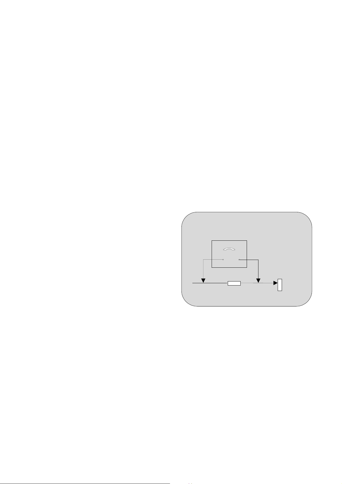
HOT CHECK CIRCUIT
a.c. VOLTMETER
2k 10 Watts
TO INSTRUMENT’S EXPOSED
METALLIC PARTS
Fig.1
WATER PIPE
(EARTH)
X-RADIATION WARNING
1. The potential sources of X-Radiation in TV sets are
the high voltage section and the picture tube.
2. When using a picture tube test jig for service, ensure
that the jig is capable of handling 30kV without
causing X-Radiation.
NOTE: It is important to use an accurate periodically
calibrated high voltage meter.
1. Set the brightness to minimum.
2. Measure the high voltage. The meter should indicate:
29kV ± 1kV.
If the meter indication is out of tolerance, immediate
service and correction is required to prevent the
possibility of premature component failure.
3. To prevent any X-Radiation possibility, it is essential
to use the specified tube.
2
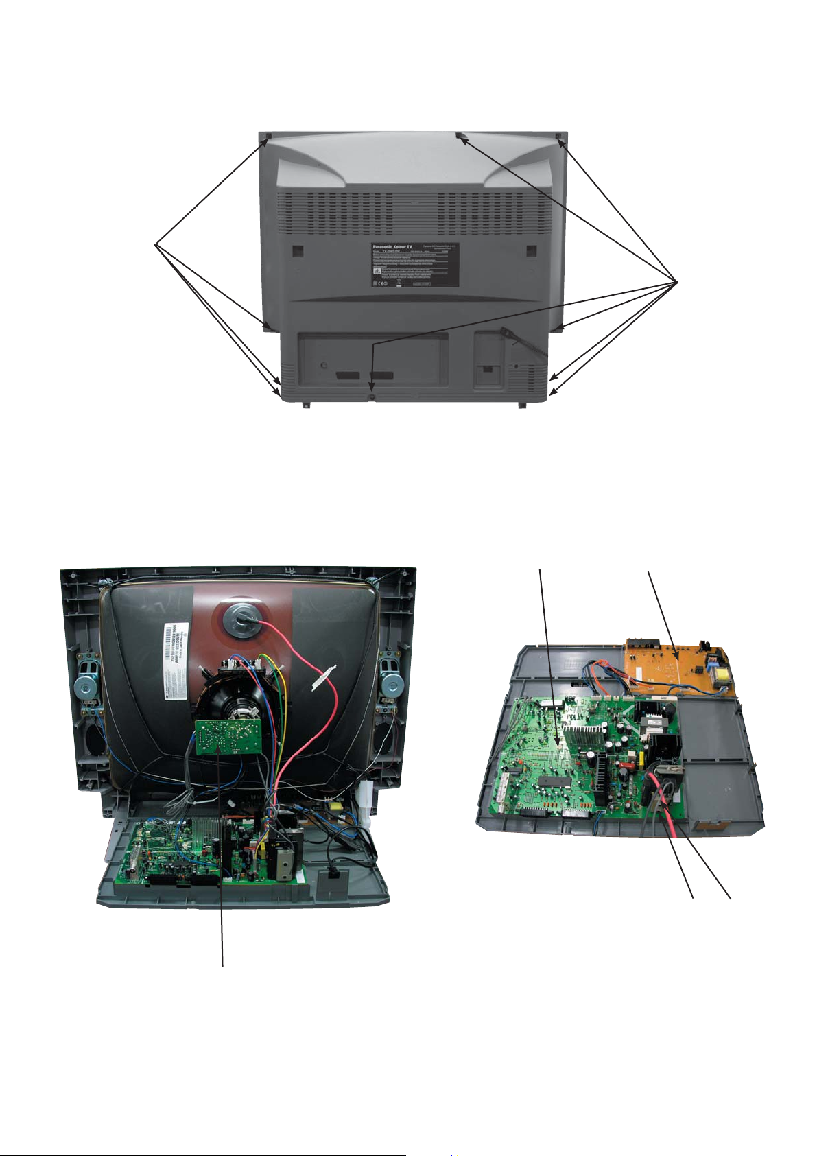
SERVICE HINTS
How to remove the rear cover
1. Remove the 10 screws as shown in Fig. 2.
SCREWS
SCREWS
Fig. 2
LOCATION OF CONTROLS
MAIN BOARD CONTROL BOARD
SCREEN FOCUS
CRT Board
Fig. 3
3
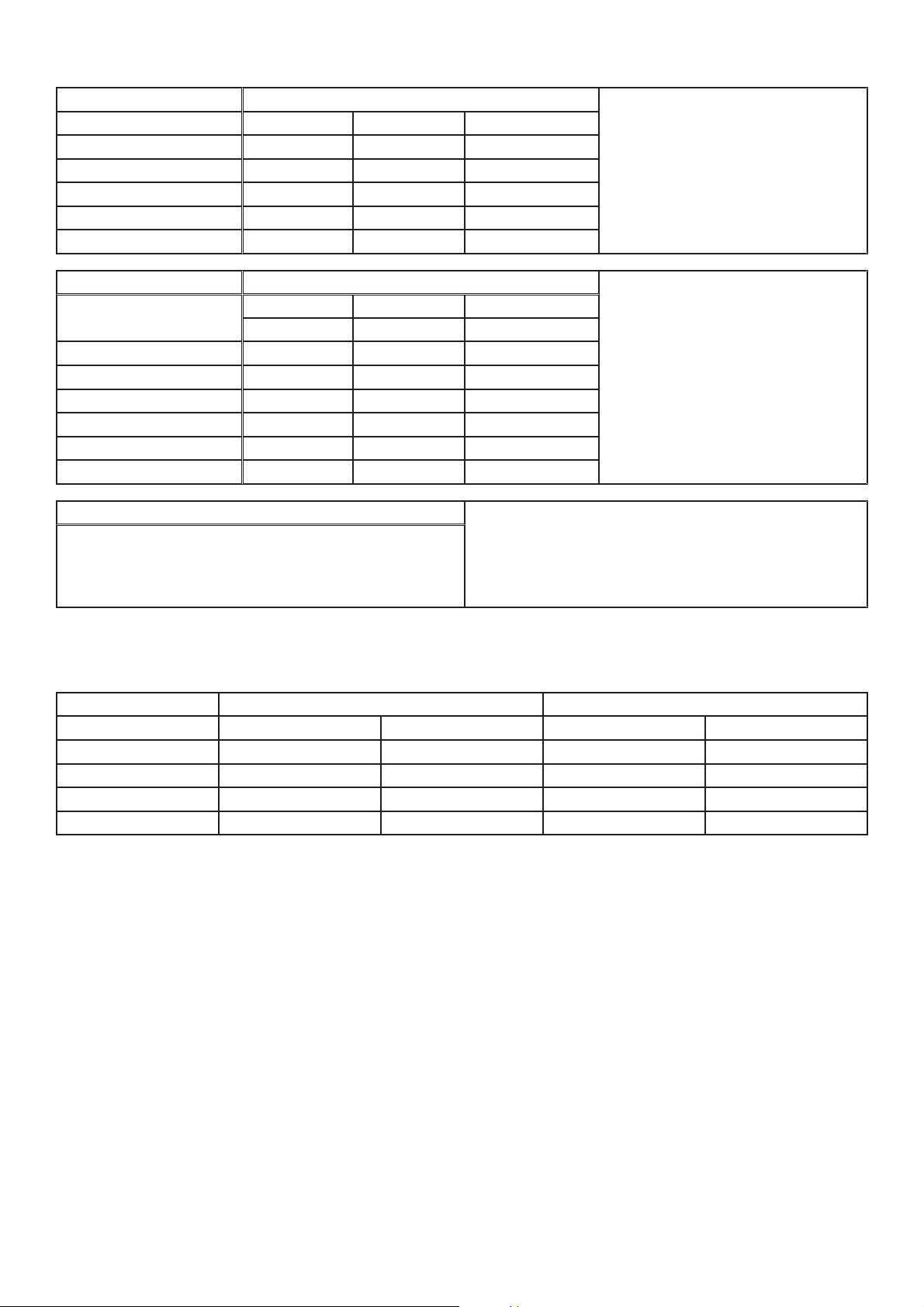
VOLTAGE CHECK
SMT 2094.0074*
MAIN B+ Voltage [V] 129 ± 1 V D820
14V [V] 13 ± 0,5 V D831
8V [V] 7,4 ± 0,5 V D830
5V [V] 4,6 ± 0,5 V D870
SOUND B+ [V] 13,2 ± 0,5 V *Volume Min.
12,8 ± 0,5 V *Volume Max.
FBT 1302.2002*
High Voltage [V]
Retrace time 5,26 ± 0,2 us
Vcp [V] 1210 ± 20 V
Video Voltage [V] 180 ± 5%
14V line [V] 14 ± 5%
52V line [V] 52 ± 5%
Heater Voltage [Vrms] 6,2 ± 5%
G2 SCREEN / CUTOFF
1. Receive a Color bar pattern
2. set the TV into Service mode.
28,08 ± 0,5 V load Max.
29,44 ± 0,5 V load Min.
Adjust the screen VR till G2-SCREEN get 32(31~33).
test conditions ;
Input voltage : 230VAC
TV set on ON mode (if nothing specified)
Picture : colour bar - Dynamic
Sound : 1Khz - (mode : Music)
test conditions ;
Input voltage : 230VAC
Ct = 11nF
Cs = 0,36uF
L linearity: TRL-040F
CRT : A68ERF182X044/M
3. Select G2 SCREEN item.
OPTION BYTES
MODEL OPTION BYTE 1 OPTION BYTE 2
TX-29E50D 0 0 1 1 1 0 0 0 0 x 38 0 1 1 0 1 0 1 1 0 x 6B
TX-29E50D/B 0 0 1 1 1 0 0 0 0 x 38 0 1 1 0 1 0 1 1 0 x 6B
TX-29PS12D 0 0 1 1 1 0 0 0 0 x 38 0 1 1 0 1 0 1 1 0 x 6B
TX-29PS12F 1 0 1 1 1 0 0 0 0 x B8 0 1 1 0 1 0 1 1 0 x 6B
TX-29PS12P 1 0 1 1 1 0 0 0 0 x B8 0 1 1 0 1 0 1 1 0 x 6B
4
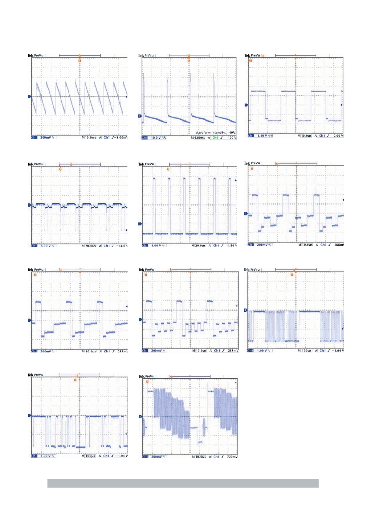
WAVEFORM PATTERN TABLE
VERTQ
I502
pin38
H-PULSE
Q401
base
VERT DRIVE
I301
pin10
FBI/SCO
I502
pin30
H OUT
I502
pin23
R OUT
I502
pin42
G OUT
I502
pin43
SDA
I501
pin6
B OUT
I502
pin44
VIDEO OUT
I501
pin52
SCL
I501
pin13
CONDITIONS: Contrast: MAX, Brightness: MID, Colour: MID, Sharpness: MID
5
ALIGNMENT SETTINGS
(The figures below are nominal and used for representative purposes only.)
To access Service Mode select program position 99 and set sharpness to minimum.
Press “MUTE” button on remote control and at the same time press the „∨” button on the customer controls at the
front of the TV, this will place the TV set into Service Mode.
Press ∧/∨buttons to step up / down through the functions.
Press + / - buttons to alter the function values.
To exit Service Mode press „MENU” button.
No
1 PARABOLA + 309
2 HOR WIDTH - 79
3CORNER T - 89
4 CORNER B - 65
5 HOR PARAL 0
6 V. LINEAR - 10
7 EW-TRAPEZ + 42
8 S CORRECT + 111
9 VERT CENT - 1
10 VERT SIZE - 8
11 SHIPPING OFF
12 HOR CEN - 140
13 RED GAIN + 345
14 GRN GAIN + 320
15 BLUE GAIN + 330
16 RED BIAS + 152
17 GRN BIAS + 288
18 AGC LEVEL + 45
19 G2 SCREEN + 32
20 AFT + 32
21 Bit0 ~ Bit7
22 Bit0 ~ Bit7
23 Bit0 ~ Bit7 0 x FF
24 AVL OFF
Setting in indication
Note : All settings are approximate
Settings / Special features
Refer to the Option Bytes(Page4)
6
h}X
X`G}
^SXXSX\G
XSZGyVs
iVnVy
YS]GyVs
h}Y
YWG}
XSZGyVs
YS]GyVs
YWG}
X\Gj
X`G}
h}Z
jy{
yG^
nG_
iG`
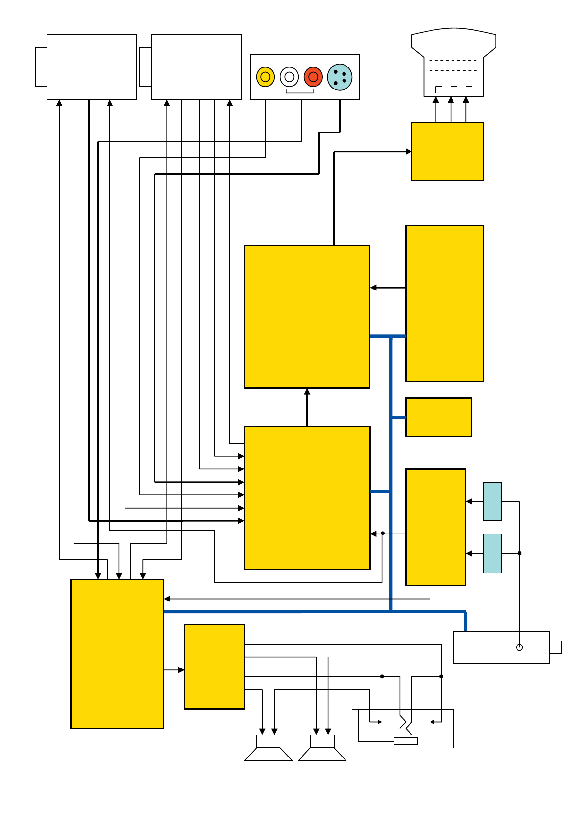
VIDEO & STEREO AUDIO BLOCK DIAGRAM
]Y
\\
\]
\^U\_
\[
\Z
Z`S[WS[X
p\WY
^\G
^]G
WGZYG
XGZXG
DISPLAY &
DEFLECTION
^^G
^_G
]\]
YGZWG
ZGYYG
p\WX
PROCESSOR
^`G
_WG
[GYXG
\GX]G
VIDEO
[YS[ZS[[
XGG
Y
]GX\G
^GXW
PROCESSOR
\XS\YS\Z
]ZS][]SXZ
cppjGi|ze
\Y
ZSYSX
p`WX
vzkV{{Gyni
Z_SZ`S[W
yGVGnVGi
XSY
\S]
pXWX
XYOj}izP
RGB
AMP
p^WX
MICRO PROCESSOR
EAROM
p^WY
XSY
[^S[]
Z]SZ^
p]WX
\ZS\Y
ZZSZ[
\WS[`
\_`SXW
Y_SY`OyVsP
SOUND PROCESSOR
]S^
}pmGGGGGGGGGGGGGzpm
Y[OzpmP
p]WY
XYS]OyVsP
XGGG[GGGX[GGX^
AUDIO AMP
zmX zmY
pm
JP01B
s
y
7
 Loading...