

Panasonic TX-29AK1F Service Manual
ORDER No. SM-99052
Colour Television
TX-29AK1F
EURO-4 Chassis
SPECIFICATIONS
Power Source: 220-240V a.c., 50Hz
Power Consumption: 100W
Standby Power
Consumption: 1,4W
Aerial Impedance: 75Ω unbalanced, Coaxial Typ e
Receiving System: PAL-B/G, H, I, D/K, PAL-525/60
Receiving Channels:
VHF E2-E12 VHF H1-H2 (ITALY)
VHF A-H (ITALY) VHF R1-R2
VHF R3-R5 VHF R6-R12
UHF E21-E69 CATV (S01-S05)
CATV S1-S10 (M1-M10) CATV S11-S20 (U1-U10)
CATV S21-S41 (HYPERBAND)
Intermediate Frequency:
Video 38,9MHz, 34MHz
Sound 32,9MHz, 33,16MHz, 33,4MHz
Colour 34,47MHz (PAL)
Video/Audi o T er m i na ls :
AUDIO MONITOR OUT Audio (RCAx2) 500mV rms1kΩ
AV1 IN Video (21 pin) 1V p-p 75Ω
AV1 OUT Video (21 pin) 1V p-p 75Ω
AV2 IN Video (21 pin) 1V p-p 75Ω
AV2 OUT Video (21 pin) 1V p-p 75Ω
AV3 IN Audio (RCAx2) 500mV rms10kΩ
High Voltage: 30,5kV ± 1kV
Picture Tube: M68LQK185X06 68cm
Audio Output: 2 x 20W (Music Power)
Headphones 8Ω Impedance
Accessories supplied: Remote Control
Dimensions:
Height: 568mm
Width: 688mm
Depth: 492mm
Net Weight: 47kg
Specifications are subject to change without notice.
Weights and dimensions shown are approximate.
NOTE: This Service Manual should be used in conjunction with the
EURO-4 technical guide.
SECAM B/G, D/K, L/L’
M.NTSC
NTSC (AV only)
40,4MHz, 32,4MHz (A2 STEREO)
33,05MHz, 34,05MH z (N ICA M)
32,66MHz, 32,4MHz (CZECH STEREO)
34,5MHz, 34,65MHz (SECAM)
Audio (21 pin) 500mV rms 10kΩ
RGB (21 pin)
Audio (21 pin) 500mV rms 1kΩ
Audio (21 pin) 500mV rms 10kΩ
S-Video IN Y: 1V p-p 75Ω
(21 pin) C: 0,3V p-p 75Ω
Audio (21 pin) 500mV rms 1kΩ
Selectable Output (21 pin)
Video (RCAx1) 1V p-p 75Ω
8Ω Impedance
2 x R6 (UM3) Batteries
TECHNISCHE DATEN
Netzpannung: 220-240V a.c., 50Hz
Leistungsaufnahme: 100W
Standby
Leistungsaufnahme: 1,4W
Antennenimpedanz: 75Ω asymmetrisch, Koaxial-Typ
Empfangssystem: PAL-B/G, H, I, D/K, PAL-525/60
Empfangsbereiche:
VHF E2-E12 VHF H1-H2 (ITALY)
VHF A-H (ITALY) VHF R1-R2
VHF R3-R5 VHF R6-R12
UHF E21-E69 CATV (S01-S05)
CATV S1-S10 (M1-M10) CATV S11-S20 (U1-U10)
CATV S21-S41 (HYPERBAND)
Zwischenfrequenz:
Video 38,9MHz, 34MHz
Sound 32,9MHz, 33,16MHz, 33,4MHz
Colour 34,47MHz (PAL)
Video/Audio A n sc hlüsse:
AUDIO MONITOR OUT Audio (RCAx2) 500mV rms1kΩ
AV1 EINGANG Video (21 pin) 1V p-p 75Ω
AV1 AUSGANG Video (21 pin) 1V p-p 75Ω
AV2 EINGANG Video (21 pin) 1V p-p 75Ω
AV2 AUSGANG Video (21 pin) 1V p-p 75Ω
AV3 EINGANG Audio (RCAx2) 500mV rms10kΩ
Hochspannung: 30,5kV ± 1kV
Bildrohre: M68LQK185X06 68cm
Ton Ausgangsl eis tu n g: 2 x 20W (Musikleistung)
Lautsprecher 8Ω Impedanz
Kopfhörer: 8Ω Impedanz
Mitgel. Zube h ör : Fernbedienung
Abmessungen:
Höhe: 568mm
Breite: 688mm
Tiefe: 492mm
Gewicht: 47kg
Änderungen der Technisichen Daten vorbehalten.
Gewichte und Abmessungen sind Näherungsangaben.
Hinweis: Bitte verwende Sie das Service Manual zusammen mit dem
Technical Guide.
SECAM B/G, D/K, L/L’
M.NTSC
NTSC (nur AV Eingang)
40,4MHz, 32,4MHz (A2 STEREO)
33,05MHz, 34,05MH z (N ICA M)
32,66MHz, 32,4MHz (CZECH STEREO)
34,5MHz, 34,65MHz (SECAM)
Audio (21 pin) 500mV rms 10kΩ
RGB (21 pin)
Audio (21 pin) 500mV rms 1kΩ
Audio (21 pin) 500mV rms 10kΩ
S-Video IN Y: 1V p-p 75Ω
(21 pin) C: 0,3V p-p 75Ω
Audio (21 pin) 500mV rms 1kΩ
Wählbarer Ausgang
Video (RCAx1) 1V p-p 75Ω
2 x R6 (UM3) Batterien

CONTENTS
SAFETY PRECAU TIO NS ....................................................2
SERVICE HINTS .................................................................4
SERVICE POSITION ...........................................................5
SELF CHECK......................................................................6
ADJUSTMENT PROCEDURE .............................................7
WAVEFORM PATTERN TABLE ..........................................8
ALIGNMENT SETTINGS .....................................................9
BLOCK DIAGRAMS.............................................................11
PARTS LOCATION..............................................................15
REPLACEMENT PARTS LIST.............................................16
SCHEMATIC DIAGRAMS....................................................27
CONDUCTOR VIEWS .........................................................32
INHALT
SICHERHEITSVORKEHRUNGEN ...................................... 2
SERVICE HINW EISE ..........................................................4
SERVICEPOSITION FÜR DAS CHASSIS...........................5
SELBSTDIAGNOSE ............................................................ 6
ABGLEICH..........................................................................7
SIGNAL TABELLE............................................................... 8
ABGLEICHTABELLE...........................................................10
SCHALTBILD BL O C K..........................................................11
EXPLOSIONSZEICHNUNG................................................. 15
ERSATZTEILLISTE............................................................. 16
SCHALTBILD SC HEMA ...................................................... 27
ANSICHT DER LEITERBAHNEN ........................................ 32
SAFETY PRECAUTIONS
GENERAL GUIDE LINES
1. It is advisable to insert an isolation transformer in the
a.c. supply before servicing a hot chassis.
2. When servicing, observe the original lead dress in the
high voltage circuits. If a short circuit is found, replace
all parts which have been overheated or damaged by
the short circuit.
3. After servicing, see that all the protective devic es
such as insulation barriers, insulation papers, shields
and isolation R-C combinations are correctly
installed.
4. When the receiver is not being used for a long period
of time, unplug the power cord from the a.c. outlet.
5. Potentials as high as 31,5kV are present when this
receiver is in operation. Operation of the receiver
without the rear cover involves the danger of a shock
hazard from the receiver power supply. Servicing
should not be attempted by anyone who is not
familiar with the precautions necessary when working
on high voltage equipment. Always discharge the
anode of the tube.
6. After servicing make the following leakage current
checks to prevent the customer from being exposed
to shock hazard.
LEAKAGE CURRENT COLD CHECK
1. Unplug the a.c. cord and connect a jumper between
the two prongs of the plug.
2. Turn on the receiver’s power switch.
3. Measure the resistance value with an ohmmeter,
between the jumpered a.c. plug and each exposed
metallic cabinet part on the receiver, such as sc rew
heads, aerials, connectors, control shafts etc. When
the exposed metallic part has a return path to the
chassis the reading should be between 4M ohm and
20M ohm. When the exposed metal does not have a
return path to the chassis the reading must be
infinite.
SICHERHEITSVORKEHRUNGEN
ALLGEMEINE RICHTLINIEN
1. Es ist empfehlenswert einen Trenntransformator in
die Stromversorgung zu schalten, bevor Reparaturen
an einem Gerät vorgenommen werden, dessen
Chassis unter Spannung steht.
2. Bei der Durchführung von Servicearbeiten dürfen die
ursprünglichen Kabelanschlüsse nicht vertauscht
werden. Dies gilt insbesondere für die Anschlüsse im
Hochspannungsteil. Hat sich ein Kurzschluß ereignet,
dann sind alle Teile, an denen Spuren von
Überhitzung sichtbar sind, auszuwechseln.
3. Nach Beenden der Servicearbeiten ist
sicherzustellen, daß alle Sicherheitsvorrichtungen,
wie Isolationsstege, Isolationspapiere,
Abschirmungen und Isolations -R-C- Glieder wieder
richtig eingesetzt sind.
4. Wenn der Fernseher während längerer Zeit nicht in
Betrieb gesetzt wird, sollte der Netzstecker aus der
Netzsteckdose gezogen werden.
5. Im Betrieb sind Spannungen bis zu 31,5kV in diesem
Gerät vorhanden. Die Inbetriebnahme des
Fernsehers ohne aufgesetzte Rückwand bringt die
Gefahr eines elektrischen Schlages von der
Fernseher - Stromversorgung mit sich.
Servicearbeiten solten daher auch nie durch
Personen versucht werden, die ni cht in vollem.
Umfang mit den Sicherheitsvorkehrungen beim
Umgang mit Hochspannungsgeräten vertraut sind.
Vor der Handhabung mit der Bildröhre ist die Anode
der Bildrohre immer an dem Empfängerchassis zu
entladen.
6. Nach Beenden der Servicearbeiten sind die
folgenden Kriechstrom-Prüfungen durchzuführen, um
den Kunden vor der Gefahr eines elektrischen
Schlages zu schützen.
MESSUNG DES ISOLATIONSWIDERSTANDES
IM ABGESCHALTETEN ZUSTAND
1. Den Netsztecker aus der Netzsteckdose ziehen und
die beiden Steckerstifte kurzschließen.
2. Den Geräteschalter des Fernsehgerätes einschalten.
3. Mit einem Ohmmeter den Widerstandswert zwischen
dem überbrückten Netzkabelste ckerund jendem
zugänglichen Metallteil am Gehäuse des
Fernsehgerätes, wie Schraubenköpfe, Antennen,
Achsen der Regler, Griffassungen usw.messen.
Wenn ein zugängliches Metallteil keine Rückleitung
zum Chassis hat, Muß die Anzeige unendlich
betrgen.
2
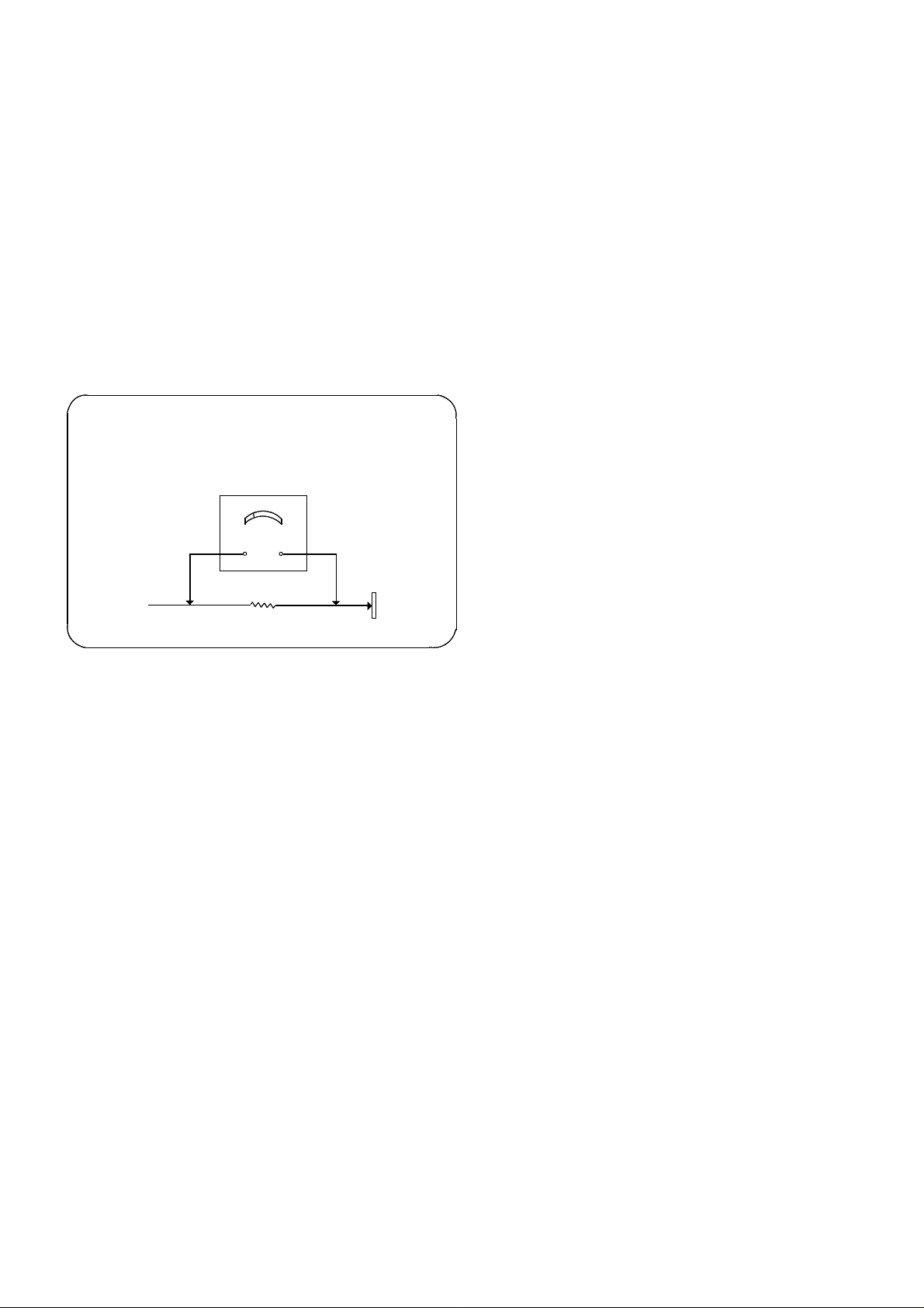
LEAKAGE CURRENT HOT CHECK
1. Plug the a.c. cord directly into the a.c. outlet. Do not
use an isolation transformer for this check.
2. Connect a 2kΩ 10W resistor in series with an
exposed metallic part on the receiver and an earth,
such as a water pipe.
3. Use an a.c. voltmeter with high impedance to
measure the potential across the resistor.
4. Check each exposed metallic part and check the
voltage at each point.
5. Reverse the a.c. plug at the outlet and repeat each of
the above measurements.
6. The potential at any point should not exceed 1,4 V
rms. In case a measurement is outside the limits
specified, there is a possibility of a shock hazard, and
the receiver should be repaired and rechecked before
it is returned to the customer.
HOT CHECK CIRCUIT
SCHALTUNGSAUFBAU FÜR PRUFUNG
IM EINGESCHALTETEN ZUSTAND
a.c. VOLTMETER
WECHSELSTROM-VOLTMETER
TO INSTRUMENT’S
EXPOSED
METALLIC PARTS
MESSUNG DES KRIECHSTROMS IM
EINGESCHALTETEN ZUSTAND
1. Den Netzstecker direkt in eine Netsteckdose stecken.
Für diese Messung keinen Trenntransformator
verwenden.
2. Einen 2kΩ / 10W-Widerstand in Serie mit einem von
außen zugänglichen Metallteil am Fernsehgerät und
einer guten, Erdung z.B Wasserleitung, anschließen.
3. Ein Wechselstrom-Voltmeter mit einem Me ßbereich
von 1000 Ohm.Volt oder größer verwenden, um die
Spannung über den Widerstand zu messen.
4. Jedes zugängliche Metallteil prüfen, und an jedem
Punkt dies Spannung messen.
5. Den Netztecker umgekehrt in die Steckdose stecken
und jede der obigen Messungen wiederholen.
6. Die Spannung darf an keinem der Punkte 1,4V eff.
überschreiten. Wird dieser Wert nicht eingehalten,
besteht die Gefar eines elektrischen Schlages, und
das Fernsehgerät sollte daher repariert und
nachgeprüft werden, bevor es an den Kunden
zurückgegeben wird.
AN ZUGANGLICHE
METALLTEILE DAS
TV-GERATES
2k ohm
Water Pipe
(Earth)
Wasserleitung
(Erdung)
Fig.1.
Abb.1.
X-RADIATION WARNING
1. The potential sources of X-Radiation in TV sets are
the high voltage section and the picture tube.
2. When using a picture tube test jig for service, ensure
that the jig is capable of handling 31,5kV without
causing X-Radiation.
NOTE : It is important to use an accurate
periodically calibrated high voltage meter.
1. Set the brightness to minimum.
2. Measure the high voltage. The meter should indicate:
30,5kV ± 1kV. If the meter indication is out of
tolerance, immediate service and correction is
required to prevent the possibility of premature
component failure.
3. To prevent any X-Radiation possibility, it is essential
to use the specified tube.
RÖNTGENSTRAHLUNG ACHTUNG :
1. Potentielle Quellen von Röntgenstrahlung in
Fernsehgeräten sind das Hochspannungsteil und die
Bildröhre.
2. Bei Verwendung eines Bildröhren-Prüfgerätes für den
Service ist sicherzustellen, daß es für die Belastung
von 30,5kV geeignet ist, ohne daß eine
Röntgenstrahlung verursacht wird.
ANMERKUNG : Es ist wichtig, daß ein präzises,
regelmäßig geprüftes Voltmeter verwendet wird.
1. Helligkeit auf Minimum stellen.
2. Die Hochspannung messen. Die Anzeige des
Instrumentes sollte: 31,5kV ± 1kV.
Falls die Anziege diese Toleranzgrenzen
überschreitet, ist die sofortige Behebung nötig, um
die Möglichkeit vorzeitigen Komponentenausfalls zu
verhüten.
3. Um die Möglichkeit von Röntgenstrahlung zu
begrenzen, ist es wichtig, daß nur die
vorgeschriebene Bildröhre verwendet wird.
3
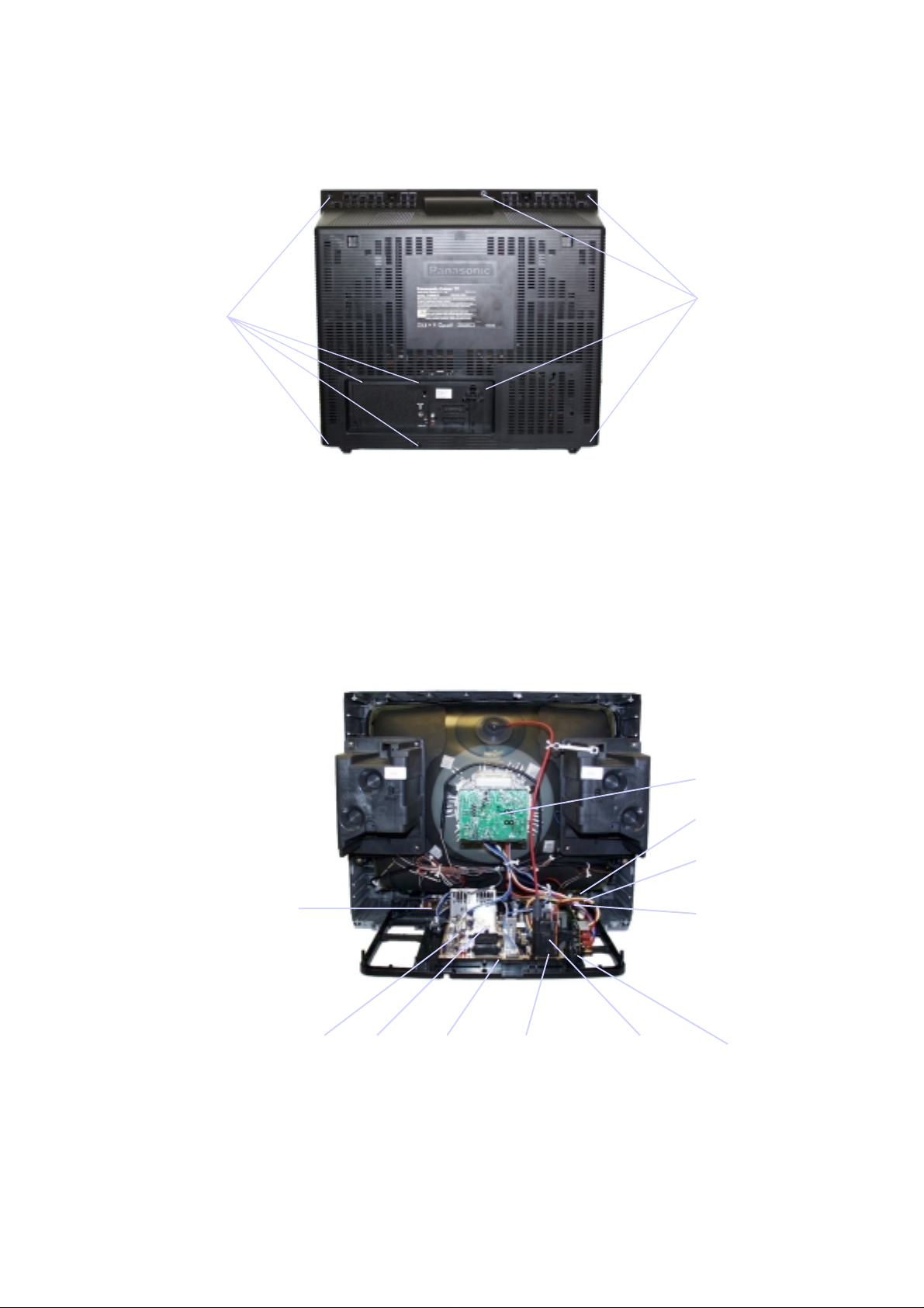
SERVICE HINTS
Screen
HOW TO REMOVE THE REAR COVER
1. Remove the 9 screws as shown in Fig.2.
SERVICE HINWEISE
ENTFERNEN DER GERÄTERÜCKWAND
1. Die 9 Schrauben entfernen, siehe Abb.2.
Screws A
Schrauben A
Fig.2.
Abb.2.
Screws A
Schrauben A
LOCATION OF CONTROLS LAGE DER EINSTELLREGLER
M-Board
H-Board
E-Board
Schirmgitterregler
Focus
Fokusregler
Y-Board
V-Board
Q-Board
N-Board
P-BoardZ-Board
4
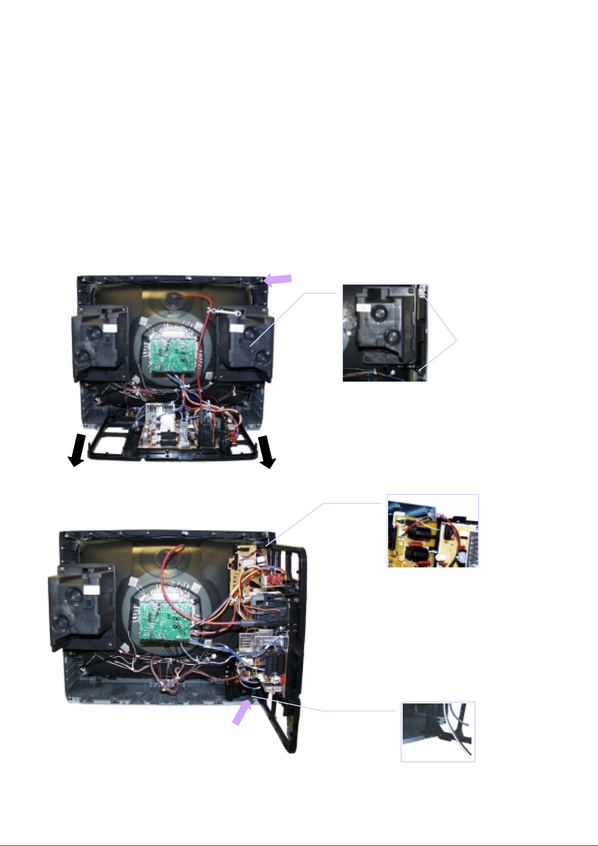
HOW TO MOVE THE CHASSIS
(
(
INTO SERVICE POSITION
1. Remove the bead clamper from the mains lead and
affix, using back cover screw, into top right-hand
cabinet rib (A), shown in Fig.3.
2. Remove 2 screws (B), as shown in Fig.4, and remove
speaker assembly.
3. Hold and lift the rear of the chassis and gently pull the
chassis toward you, as shown in Fig.3.
4. Release the respective wiring clips and rotate the
chassis vertically through 90°, anti-clockwise.
5. Locate the base of the chassis frame into location (C),
shown in Fig.5 / Fig.7.
6. Clip the chassis frame onto the bead clamper, shown
in Fig.5 / Fig.6.
7. After servicing replace the bead clamper and speaker,
and ensure all wiring is returned to its original position
before returning the receiver to the customer.
SERVICEPOSITION FÜR DAS CHASSIS
1. Entfernen Sie den Kabelbinder von der Netzleitung und
befestigen Sie ihn mit einer Rückwandschraube am Gehäuse
an der Position (A). (Abb.3.)
2. Nach dem Lösen der zwei Schrauben (B) kann der rechte
Lautsprecher (Abb.4) ausgebaut werden.
3. Das Chassis am hinteren Ende anheben und vorsichtig
herausziehen (Abb.3).
4. Die Kabelhalter werden gelöst und das Chassis gegen den
Uhrzeigersinn um 90º gedreht.
5. Das untere Ende des Chassis wird in die Halterung (C)
gesteckt (Abb.5 / Abb.7).
6. Das obere Ende des Chassis wird in den Kabelbinder
eingehängt (Abb.5 / Abb.6).
7. Nach der Reparatur wird der Lautsprecher wieder eingebaut,
der Kabelbinder entfernt und alle Kabelbäume auf die
Originalposition in die Halterungen eingesetzt.
A)
Screws
Schrauben
(B)
Fig.3.
Abb.3.
Fig.4.
Abb.4.
Fig.6.
Abb.6.
Fig.5.
Abb.5.
C)
Fig.7.
Abb.7.
5
SELF CHECK
Service-Hilfen
1. Self-check is used to automatically check the bus
lines and hexadecimal code of the TV set.
2. To get into the Self-Check mode press the down
(-/v) button on the customer controls at the front of
the set,at the same time pressing the STATUS
button on the remote control, and the screen will
show :-
SELBSTDIAGNOSE
1. Die Selbstdiagnose dient zum automatischen Prüfen
der Bus-Leitungen sowie des Hexadezimalcodes des
FS-Geräts. Zum Umschalten auf Selbstdiagnose
zunächst die Taste "STATUS" auf der
Fernbedienung und gleichzeitig die-Taste am
Bedienteil des FS-Gerätes drücken (-/v), auf dem
Bildschirm erscheint hierauf :-
2. Nach der Selbstdiagnose wird das Gerät automatisch
auf sämtliche werksseitigen Standardeinstellungen
zurückgesetzt :-
VDP O.K.
TUN O.K.
E2 O.K.
MSP O.K.
DPL - -
OPTION1 39
OPTION2 3C
OPTION3 1F
OPTION4 40
OPTION5 FF
OPTION6 65
If the CCU ports have been checked and found to be incorrect or not located then " - - " will appear in place of "O.K.".
Wenn der Hauptprozesser (CCU) an den Anschlüssen einen Fehl er erkennt, oder der entsprechende Anschluss nicht belegt
, zeigt die entsprechende Position " - - " anstelle von OK an.
ist
PCB O.K.
Cab O.K.
Sum Factory use
only
Nur für
Herstellung
Service Aids
To aid in the service of our current chassis there are a number
of Service Aids which have been made available.
• LUCI interface kit (Linked Utility Computer Interface)
Part number: TZS6EZ002
This contains interface and cables for connecting TV
service connector and a PC as well as diagnostic software.
As new models are introduced upgrade software will
become available.
Zur Unterstützung der Servicearbeiten stehen weitere
Hilfsmittel zur Verfügung.
• LUCI interface kit (PC-unterstützes Diagnosesystem)
Bestell-Nr.: TZS6EZ002
Es beinhaltet ein Interface, die Anschlusskabel zum FSGerät und die Diagnose-Software. Bei Einführung von
neuen Modellen ist ein Update der Software jederzeit
möglich.
• VICI (Visual Interactive Computer Information)
• TASMIN (Technically Advanced System for Multimedia
These C.D.'s contain multimedia documentation providing
quick access to service in formation.
Part No. TZS7EZ006, TZS7EZ005 & TZS8EZ001
1. Service Manuals
2. Instruction Books
3. Technical Information
Interactive Notes)
As well as providing a first step towards more interactiv e
training this product also achieves quick access to
Technical Information.
• VICI (Interaktive CD-ROM) mit schnellem Zugiff auf
Serviceinformationen.
Bestell-Nr.:TZS7EZ006, TZS7EZ005 & TZS8EZ001
1. Service Manuals
2. Bedienungsanleitungen
3. Technical Information
• TASMIN (Technisch erweitertes System für interaktive
Multimedia-Hinweise und Notiz en)
Genauso wie dieses Produkt einen ersten Schritt in
Richtung erweitertes interaktives Training bereitstellt,
ermöglicht es einen noch schnelleren Zugang zu
technischen Informationen.
6
ADJUSTMENT PROCEDURE
Item/Preparation Adjustments
+B SET-UP
1. Receive a Greyscale signal.
2. Set the controls:Brightness Minimum
Contrast Minimum
Volume Minimum
Cut-Off / Ug2 Test
1. Receive a Greyscale signal.
2. Degauss the tube externally.
3. Set the TV into Service Mode 1.
4. Select Cutoff mode.
1. Set the +B voltage up as follows:Adjust R811 so that B2 shows 148V±1V
2. Confirm the following voltages.
B9 5 ± 0,25V B10 5 ± 0,25V
B5 12 ± 0,5V B11 33 ± 1,5V
B4 16 ± 1V B7 8 ± 0,5V
B12 26 ± 1V B8 5,5 ± 0,5V
B3 35 ± 1V B13 15 ± 1V
B1 200 ± 10V B14 -15 ± 1V
To adjust Cutoff connect an oscilloscope to the Blue
cathode.Press "STR" and adjust "cutoff" value using the
"Yellow" and "Blue" buttons until the black level is
160V±5V, press "STR" to store the value. Remove the
oscilloscope.
Select Ug2 adjustment and adjust the screen VR until the
display shows "O.K."
ABGLEICH
Vorbereitungen Abgleich
+B - Abgleich
1. Testbild empfangen.
Helligkeit auf Minimum
Kontrast auf Minimum
Lautstärke Minimum
Cut-Off / Ug2 Test
1. Testbild empfangen.
2. Bildröhre entmagnetisieren.
3. Service-Mode 1 anwählen.
4. Im Service-Mode den Abgleichpunkt Cutoff DC-Mode
wählen.
1. Mit R811 muß die B2 auf 148V±1V einges tel lt
werden.
2. Folgende Spannungen sind zu überprüfen.
B9 5 ± 0,25V B10 5 ± 0,25V
B5 12 ± 0,5V B11 33 ± 1,5V
B4 16 ± 1V B7 8 ± 0,5V
B12 26 ± 1V B8 5,5± 0,5V
B3 35 ± 1V B13 15 ± 1V
B1 200± 10V B14 -15± 1V
Einen Oszillographen an die blaue Katode der Bildröhre
anschliessen. STR-Taste drücken und Mit der gelben
und blauen Taste den CUT-OFF Wert auf 160V±5V
abgleichen und mit der STR-Taste abspeichern. Den
Oszillograph entfernen und den Ug2 Test aufrufen. Den
Abgleichwert solange ändern, bis OK auf dem Bildschirm
erscheint. Den Wert abspeichern.
7
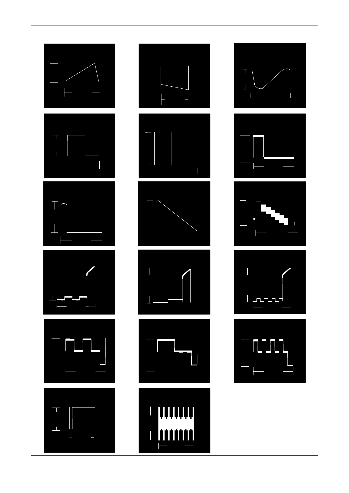
Vert Out
IC601 Pin 31
WAVEFORM PATTERN TABLE SIGNAL TABELLE
Vert Drive
IC451 Pin 2
VFLB
IC451 Pin 3
0.7V
H - Out
IC601 Pin 50
3V
HFLB
IC601 Pin 13
6.2V
20mS
64µS
64µS
57V
H - Out
IC701 Pin 5
30mV
HFLB
IC701 Pin 8
1.5V
20mS
64µS
64µS
1V
20mS
H - Pulse
Base Q503
2V
64µS
Video Out
IC601 Pin 59
2V
64µS
R - Out
IC601 Pin 37
275mV
R - Out
E8 Pin 5
4.6V
SCL
IC1201 Pin 3
3.7V
64µS
64µS
G - Out
IC601 Pin 38
275mV
G - Out
E8 Pin 3
4.4V
SVM Out
IC601 Pin 34
88mV
64µS
64µS
B - Out
IC601 Pin 39
275mV
64µS
B - Out
E8 Pin 4
4.6V
64µS
13µS
64µS
8
ALIGNMENT SETTINGS:
(The figures below are nominal and used for representative purposes only.)
Alignment Function Settings / Special features
Horizontal Position
Vertical Position
Horizontal Amplitude
Vert. Amplitude
EW-amplitude
EW-amplitude
Trapezium-comp
Trapezium-comp
H-Pos
061
V-Pos
005
H-Amp
055
V. Amp
054
E/W-Amp1
-128
E/W-Amp2
006
Trapez-1
047
Trapez-2
-128
Optimum setting.
Optimum setting.
Optimum setting.
Optimum setting.
Optimum setting.
Optimum setting.
Optimum setting.
Optimum setting.
Vertical Linearity
Vertical Symmetry
DVCO
Cut-off DC
Ug2 Test
Highlight
Lowlight
Sub-Brightness
V-Lin
006
V-Sym
002
DVCO
-005
Cut-off
0171
Ug2
055
O.K.
High 0902 0777 0864
Low 0117 0132 0112
Sub-Brightness
255
Optimum setting.
Optimum setting.
Receive a PAL Colour Bar Pattern. For
DVCO alignment press "Blue" button, wait
until the colours are changing slowly and
press "STR".
To adjust Cutoff connect an oscilloscope to
the blue cathode, adjust "cutoff" value
using the "Yellow" and "Blue" buttons until
the black level is 160V±5V press "STR" to
store the value. Remove the oscilloscope.
Select Ug2 adjustment and adjust the
screen VR until the display shows "O.K."
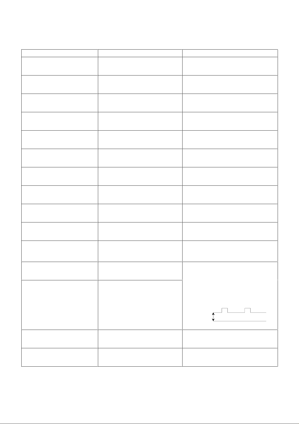
Black Level
160V±5V
GND
Optimum setting.
Optimum setting.
9
ABGLEICHTABELLE
(Die angegebenen Werte sind Mittelwerte und Können individuell nach oben oder unten nach dem korrekten Abgleich
abweichen.)
Abgleichfunktion Einstellung / Besondere Merkmale
Horizontale position
Vertikale Position
Horizontale Amplitude
Vertikale Amplitude
OW-amplitude
OW-amplitude
Trapez-Kompensation
Trapez-Kompensation
H-Pos
061
V-Pos
005
H-Amp
055
V-Amp
054
E/W-Amp1
-128
E/W-Amp2
006
Trapez-1
047
Trapez-2
-128
Optimale Einstellung.
Optimale Einstellung.
Optimale Einstellung.
Optimale Einstellung.
Optimale Einstellung.
Optimale Einstellung.
Optimale Einstellung.
Optimale Einstellung.
Vertikale linearität
Vertikale Symmetrie
DVCO
Cut-off
Ug2 Test
Highlight
Lowlight
V-Lin
006
V-Sym
002
DVCO
-005
Cut-off
0171
Ug2
055
O.K.
High 0902 0777 0864
Low 0117 0132 0112
Optimale Einstellung.
Optimale Einstellung.
Ein Farbbalken-Testbild empfangen. Zum
Abgleich des Farboszillators (DVCO) die
blau Taste drücken. Nachdem ein leichtes
Flackern in den Farbbalken zum Stillstand
gekommen ist, die STR-Taste drücken.
Einen Oszillographen an die bl aue Katode
der Bildröhre anschliessen. STR-Taste
drücken und Mit der gelben und blauen
Taste den CUT-OFF Wert auf 160V±5V
abgleichen und mit der STR-Taste
abspeichern. Den Oszillograph entfernen
und den Ug2 Test aufrufen. Den
Abgleichwert solange ändern, bis OK auf
dem Bildschirm erscheint. Den Wert
abspeichern.
Black Level
160V±5V
Optimale Einstellung.
Sub-Brightness
Sub-Brightness
255
10
Optimale Einstellung.
11
,Q
Q35
,Q
&
Q35
AV1
9LGHR2XW
%OXH
*UHHQ
5HG
9LGHR
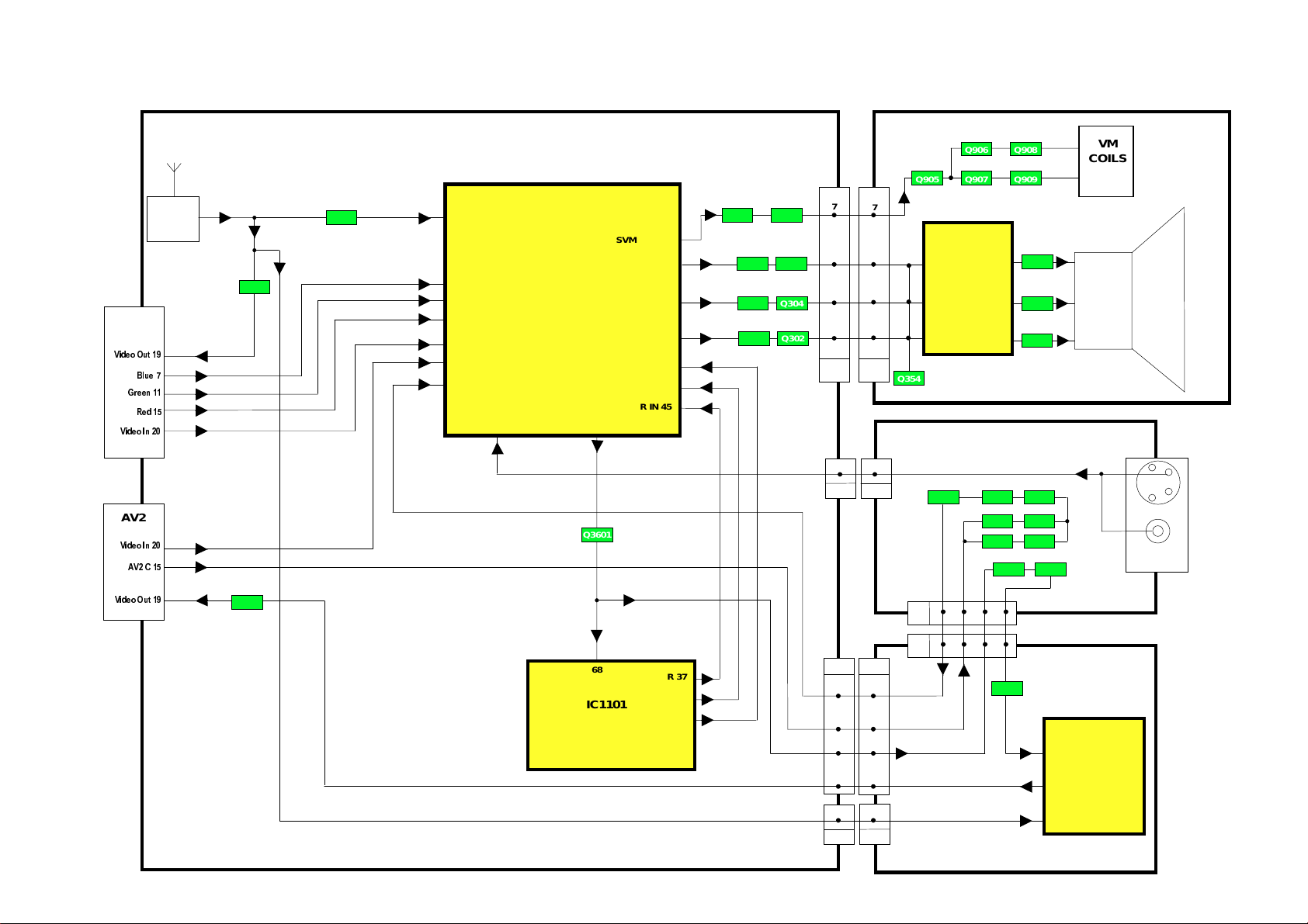
E - BOARD
VIDEO BLOCK DIAGRAM BILDSIGNAL BLOCKSCHEMA
Y - BOARD
Q908Q906
Q905 Q907 Q909
7
7
4
4
3
IC351
7
Q353
RGB
4
OUTPUT
2
1
2
8
9
1
3
3
5
5
Y2
M - BOARD
Q105
Q104
61 V IN 1
43 B IN
42 G IN
41 R IN
62 VIN 2
63 VIN 3
60 C IN
VIN 4
64
IC601
VIDEO
PROCESSOR
VIDEO OUT
59
SVM OUT 34
B OUT 39
G OUT 38
R OUT 37
B IN 47
G IN 46
R IN 45
Q950 Q951
Q303
Q304
Q301
Q302
E8
VM
COILS
CRT
AV2
9LGHR
9LGHR
$9
2XW
6 6
M2E17
Q3001
Q3601
M3
H2
E15
242
6
8
1 1
E61
H1
4
6
8
H3
68
CVBS
IC1101
MICRO
PROCESSOR
R 37
G 38
B 39
42 86
42 86
Q3206 Q3205Q3207
Q3203 Q3204
Q3201 Q3202
Q3208 Q3209
Q3402
H - BOARD
IC3401
8
VIDEO
SWITCHING
6
3
C
Y
AV3
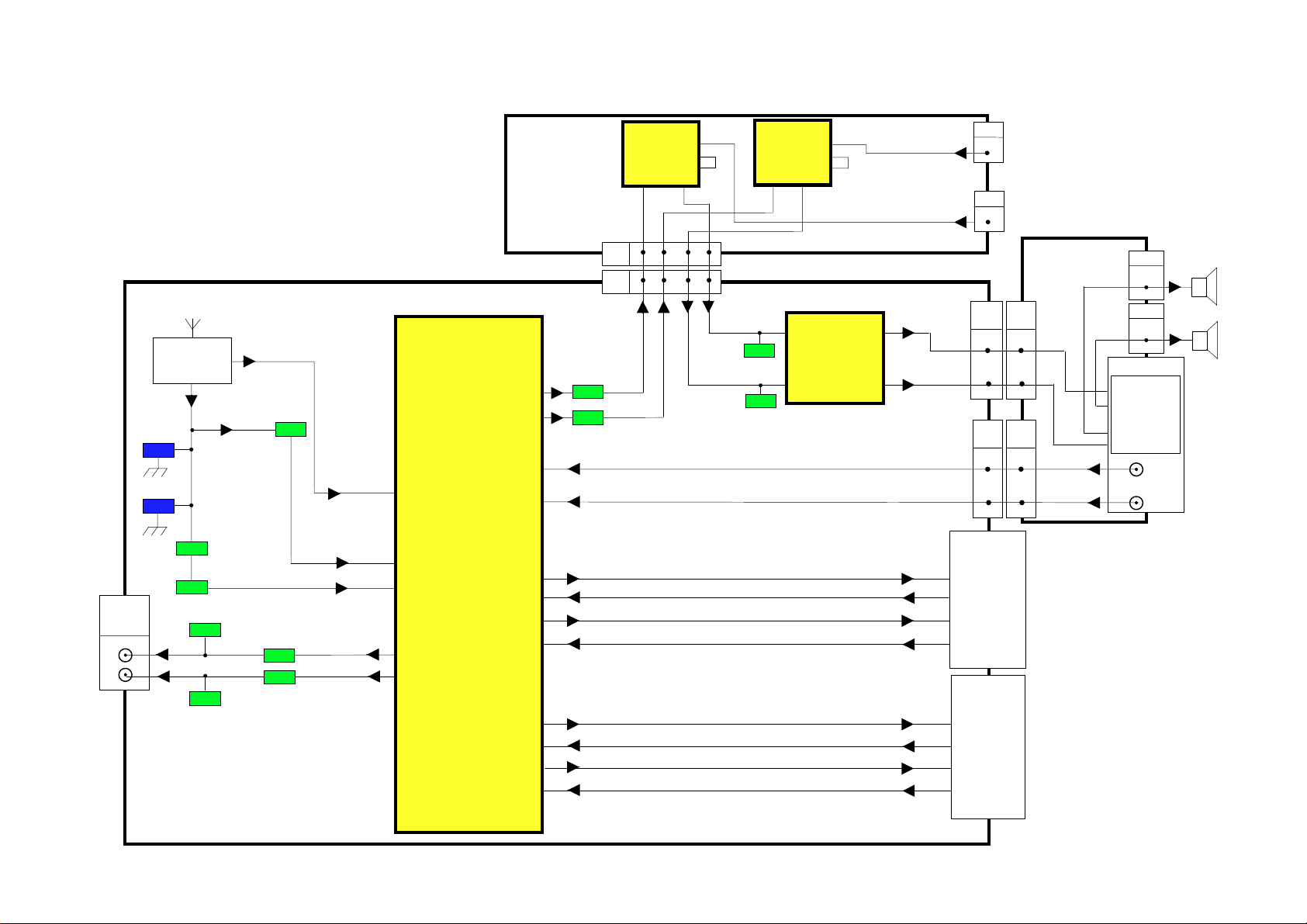
AUDIO BLOCK DIAGRAM TONSIGNAL BLOCKSCHEMA
Q103
12
AUDIO
MONITOR
OUT
E - BOARD
TUNER
X101
X102
Q101
Q102
Q2303
Q2301
Q2304
Q2302
IC2101
AUDIO
PROCESSOR
44 MONO IN
49 ANA_IN2+
47 ANA_IN1+
21 DACA_R
22 DACA_L
Z - BOARD
DACM_R 24
DACM_L 25
SC3_IN_L 37
SC3_IN_R 38
SC1_OUT_R 30
SC1_IN_R 42
SC1_OUT_L 31
SC1_IN_L 41
SC2_OUT_R 27
SC2_IN_R 40
SC2_OUT_L 28
SC2_IN_L 39
Q2102
Q2103
Z4
E10
IC2201
AMP
10
12 65
12 65
Z5
L MIC
1
Z2
R MIC
2
E16A1M1
2 2
E1710M2
10
8 8
M - BOARD
1
M4
1
M5
3
AV3
6 R
7 R
HEADPHONE
5 L
4 L
L
R
Q252
IC2221
AMP
10
5 R
8
2
1
9
IC251
AUDIO
R 7
2
1
9
8
OUTPUT
2 L
Q251
L 11
1 R OUT
2 R IN
3 L OUT
6 L IN
AV1
1 R OUT
2 R IN
3 L OUT
6 L IN
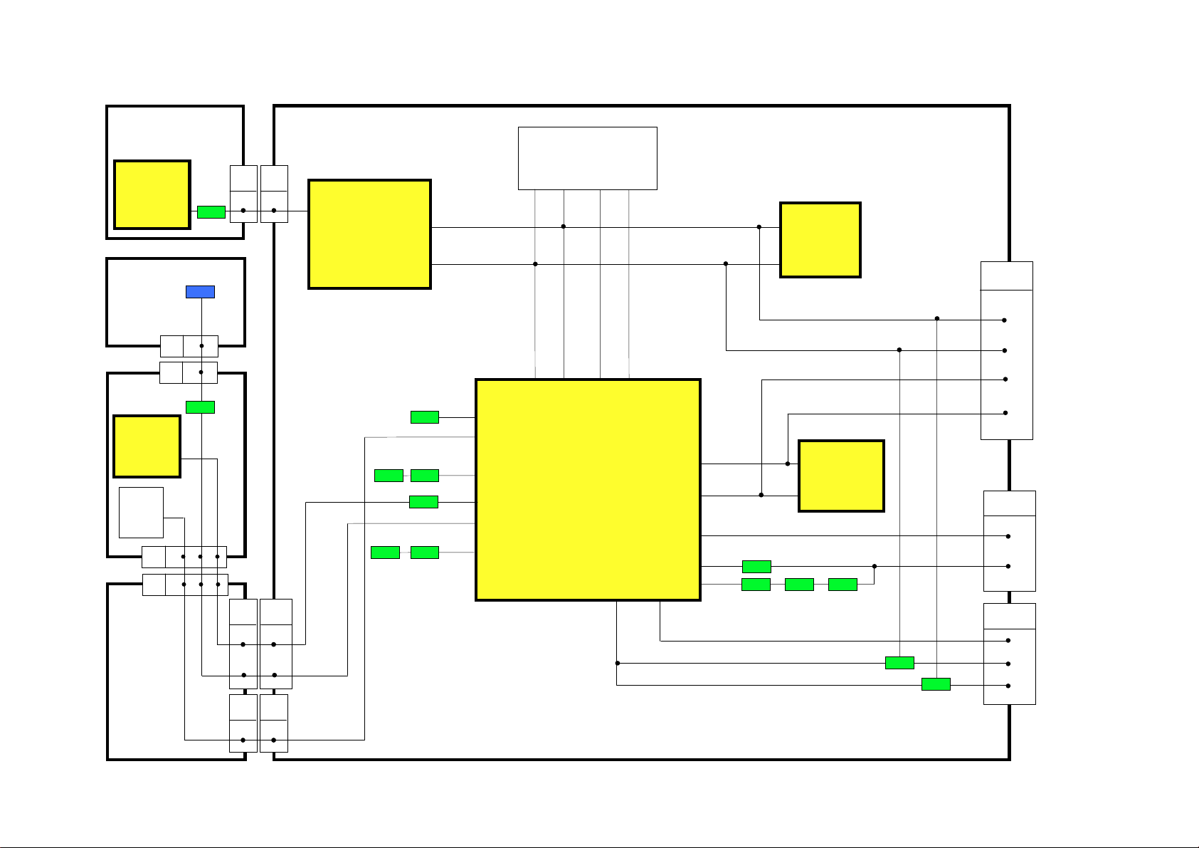
CONTROL BLOCK DIAGRAM STROMVERSORGUNGS BLOCKSCHEMA
H - BOARD
E - BOARD
TUNER
13
IC3401
VIDEO
SWITCHING
V - BOARD
N5
N - BOARD
IC1051
REMOTE
CONTROL
RECEIVER
LOCAL
KEYS
SWITCH
MATRIX
N4
M10
M - BOARD
5
V1
4 1 3
4 1 3
H31E63
1
IC2101
4
AUDIO
PROCESSOR
8
7
SDA 1
SCL 1
SCL SDA
L/L’ POS/NEG
IC601
4
VIDEO
PROCESSOR
3
SERVICE / TEST
E18
6
SDA 1
7
L/L’
83 82
POS/NEG
SCL 2
50
SDA 2
51
SLOW 2
59
OUT
72
IN
73
5855
IC1103
6
EAROM
5
SCL
7
VPROT
71
KEYSCAN
ON/OFF
PROT 1
R.C.
L.E.D.
60
52
74
81
75
SDA
48 49
IC1101
MICRO
PROCESSOR
M18E16A
SLOW 1
7 7
8
SERVICE
5
4
3
AV2
8
10
AV1
8
10
12
SCL 1
SDA 2
SCL 2
SLOW 2
AV LINK
SLOW 1
SCL 1
SDA 1
M25E17
5
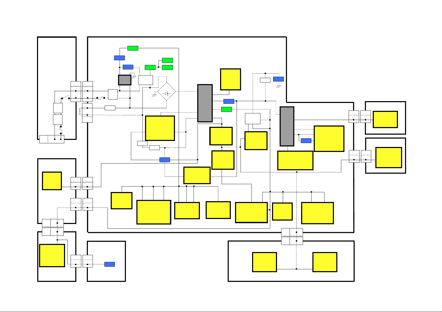
POWER SUPPLY BLOCK DIAGRAM STROMVERSORGUNGS BLOCKSCHEMA
14
N - BOARD
Line
Filter
Line
Filter
4 1
N1
Mains
In
M - BOARD
IC1900
G.M.C.
10
2
M10
2
N4
IC1051
REMOTE
CONTROL
RECEIVER
N - BOARD
S840
N2
F841
M83E21
M23E17
N58V1
E - BOARD
3
IC801
POWER
SUPPLY
R814
D805
5V SBY
Q855
Q854
~
D801
~
+
4
13132
IC1102
EPROM
2
IC850
REG
T801
P1
P2
B1
IC251
33V
AUDIO
OUTPUT
10
7V
15V
12V
150V
1
IC851
REG
3
1
IC853
29V
D850
Q850
TUNER
9V
3
1
IC852
REG
S7
S2
S5
S4
REG
3
1
8V
833
IC1103
EAROM
IC2101
AUDIO
PROCESSOR
Z - BOARD
R854
5V
5V
46
16
IC2201
AMP
D862
33V
5V
IC1105
RESET
4
T551
9
2
200V
-14V
6
14V
5
8
6
D454
27V
IC701
EW
CORRECTION
2
PROCESSOR
8
E10
8
Z4
1
6
3
15
IC601
VIDEO
4
IC451
V-OUTPUT
58
IC2201
AMP
E32Y3
E621H3
Y - BOARD
2
6
OUTPUT
H - BOARD
2
7
SWITCHING
IC351
RGB
IC3401
VIDEO
Q852
D867
D868
E1
4
4
1
2
1
F802
Degauss Coil
1
T802 RL801
Line
Filter
R802
Q853
E2
1
R805
3
2
IC1104
3
RESET
5V SBY
24366
IC1101
MICRO
PROCESSOR
V - BOARD
8
D805
 Loading...