

Page 1

Panasonic¡Panasonic¡Panasonic¡Panasonic¡Panasonic¡Panasonic¡Panasonic¡Panasonic¡P
a
a
o
i
¡
a
a
o
i
¡
a
a
o
i
¡
a
a
o
i
¡
a
a
o
i
¡
a
a
o
i
¡
a
a
o
i
¡
a
a
o
i
¡
a
a
o
i
¡
a
a
o
i
¡
a
a
o
i
¡
a
nasonic¡Panasonic¡Panasonic¡Panasonic¡Panasonic¡Panasonic¡Panasonic¡Panasonic¡Pan
sonic¡Panasonic¡Panasonic¡Panasonic¡Panasonic¡Panasonic¡Panasonic¡Panasonic¡Panas
nic¡Panasonic¡Panasonic¡Panasonic¡Panasonic¡Panasonic¡Panasonic¡Panasonic¡Panason
c¡Panasonic¡Panasonic¡Panasonic¡Panasonic¡Panasonic¡Panasonic¡Panasonic¡Panasonic
Panasonic¡Panasonic¡Panasonic¡Panasonic¡Panasonic¡Panasonic¡Panasonic¡Panasonic¡P
nasonic¡Panasonic¡Panasonic¡Panasonic¡Panasonic¡Panasonic¡Panasonic¡Panasonic¡Pan
sonic¡Panasonic¡Panasonic¡Panasonic¡Panasonic¡Panasonic¡Panasonic¡Panasonic¡Panas
nic¡Panasonic¡Panasonic¡Panasonic¡Panasonic¡Panasonic¡Panasonic¡Panasonic¡Panason
c¡Panasonic¡Panasonic¡Panasonic¡Panasonic¡Panasonic¡Panasonic¡Panasonic¡Panasonic
Panasonic¡Panasonic¡Panasonic¡Panasonic¡Panasonic¡Panasonic¡Panasonic¡Panasonic¡P
nasonic¡Panasonic¡Panasonic¡Panasonic¡Panasonic¡Panasonic¡Panasonic¡Panasonic¡Pan
sonic¡Panasonic¡Panasonic¡Panasonic¡Panasonic¡Panasonic¡Panasonic¡Panasonic¡Panas
nic¡Panasonic¡Panasonic¡Panasonic¡Panasonic¡Panasonic¡Panasonic¡Panasonic¡Panason
c¡Panasonic¡Panasonic¡Panasonic¡Panasonic¡Panasonic¡Panasonic¡Panasonic¡Panasonic
Panasonic¡Panasonic¡Panasonic¡Panasonic¡Panasonic¡Panasonic¡Panasonic¡Panasonic¡P
nasonic¡Panasonic¡Panasonic¡Panasonic¡Panasonic¡Panasonic¡Panasonic¡Panasonic¡Pan
sonic¡Panasonic¡Panasonic¡Panasonic¡Panasonic¡Panasonic¡Panasonic¡Panasonic¡Panas
nic¡Panasonic¡Panasonic¡Panasonic¡Panasonic¡Panasonic¡Panasonic¡Panasonic¡Panason
c¡Panasonic¡Panasonic¡Panasonic¡Panasonic¡Panasonic¡Panasonic¡Panasonic¡Panasonic
Panasonic¡Panasonic¡Panasonic¡Panasonic¡Panasonic¡Panasonic¡Panasonic¡Panasonic¡P
nasonic¡Panasonic¡Panasonic¡Panasonic¡Panasonic¡Panasonic¡Panasonic¡Panasonic¡Pan
sonic¡Panasonic¡Panasonic¡Panasonic¡Panasonic¡Panasonic¡Panasonic¡Panasonic¡Panas
nic¡Panasonic¡Panasonic¡Panasonic¡Panasonic¡Panasonic¡Panasonic¡Panasonic¡Panason
c¡Panasonic¡Panasonic¡Panasonic¡Panasonic¡Panasonic¡Panasonic¡Panasonic¡Panasonic
Panasonic¡Panasonic¡Panasonic¡Panasonic¡Panasonic¡Panasonic¡Panasonic¡Panasonic¡P
nasonic¡Panasonic¡Panasonic¡Panasonic¡Panasonic¡Panasonic¡Panasonic¡Panasonic¡Pan
sonic¡Panasonic¡Panasonic¡Panasonic¡Panasonic¡Panasonic¡Panasonic¡Panasonic¡Panas
nic¡Panasonic¡Panasonic¡Panasonic¡Panasonic¡Panasonic¡Panasonic¡Panasonic¡Panason
c¡Panasonic¡Panasonic¡Panasonic¡Panasonic¡Panasonic¡Panasonic¡Panasonic¡Panasonic
Panasonic¡Panasonic¡Panasonic¡Panasonic¡Panasonic¡Panasonic¡Panasonic¡Panasonic¡P
nasonic¡Panasonic¡Panasonic¡Panasonic¡Panasonic¡Panasonic¡Panasonic¡Panasonic¡Pan
sonic¡Panasonic¡Panasonic¡Panasonic¡Panasonic¡Panasonic¡Panasonic¡Panasonic¡Panas
nic¡Panasonic¡Panasonic¡Panasonic¡Panasonic¡Panasonic¡Panasonic¡Panasonic¡Panason
c¡Panasonic¡Panasonic¡Panasonic¡Panasonic¡Panasonic¡Panasonic¡Panasonic¡Panasonic
Panasonic¡Panasonic¡Panasonic¡Panasonic¡Panasonic¡Panasonic¡Panasonic¡Panasonic¡P
nasonic¡Panasonic¡Panasonic¡Panasonic¡Panasonic¡Panasonic¡Panasonic¡Panasonic¡Pan
sonic¡Panasonic¡Panasonic¡Panasonic¡Panasonic¡Panasonic¡Panasonic¡Panasonic¡Panas
nic¡Panasonic¡Panasonic¡Panasonic¡Panasonic¡Panasonic¡Panasonic¡Panasonic¡Panason
c¡Panasonic¡Panasonic¡Panasonic¡Panasonic¡Panasonic¡Panasonic¡Panasonic¡Panasonic
Panasonic¡Panasonic¡Panasonic¡Panasonic¡Panasonic¡Panasonic¡Panasonic¡Panasonic¡P
nasonic¡Panasonic¡Panasonic¡Panasonic¡Panasonic¡Panasonic¡Panasonic¡Panasonic¡Pan
sonic¡Panasonic¡Panasonic¡Panasonic¡Panasonic¡Panasonic¡Panasonic¡Panasonic¡Panas
nic¡Panasonic¡Panasonic¡Panasonic¡Panasonic¡Panasonic¡Panasonic¡Panasonic¡Panason
c¡Panasonic¡Panasonic¡Panasonic¡Panasonic¡Panasonic¡Panasonic¡Panasonic¡Panasonic
Panasonic¡Panasonic¡Panasonic¡Panasonic¡Panasonic¡Panasonic¡Panasonic¡Panasonic¡P
nasonic¡Panasonic¡Panasonic¡Panasonic¡Panasonic¡Panasonic¡Panasonic¡Panasonic¡Pan
sonic¡Panasonic¡Panasonic¡Panasonic¡Panasonic¡Panasonic¡Panasonic¡Panasonic¡Panas
nic¡Panasonic¡Panasonic¡Panasonic¡Panasonic¡Panasonic¡Panasonic¡Panasonic¡Panason
c¡Panasonic¡Panasonic¡Panasonic¡Panasonic¡Panasonic¡Panasonic¡Panasonic¡Panasonic
Panasonic¡Panasonic¡Panasonic¡Panasonic¡Panasonic¡Panasonic¡Panasonic¡Panasonic¡P
nasonic¡Panasonic¡Panasonic¡Panasonic¡Panasonic¡Panasonic¡Panasonic¡Panasonic¡Pan
sonic¡Panasonic¡Panasonic¡Panasonic¡Panasonic¡Panasonic¡Panasonic¡Panasonic¡Panas
nic¡Panasonic¡Panasonic¡Panasonic¡Panasonic¡Panasonic¡Panasonic¡Panasonic¡Panason
c¡Panasonic¡Panasonic¡Panasonic¡Panasonic¡Panasonic¡Panasonic¡Panasonic¡Panasonic
Panasonic¡Panasonic¡Panasonic¡Panasonic¡Panasonic¡Panasonic¡Panasonic¡Panasonic¡P
T X --- 2 8 P L 1
Colour Television
(U.K. Standard)
Operating Instructions
TQB8E3449 ---2
Page 2

WELCOME
Dear Panasonic Customer,
Welcome to the Panasonic family of customers. We hope that you have many years of enjoyment from your
new colour television. This is a very advanced television; however, the Quick Start Guide will allow you to use
the TV as quickly as possible. You can then read the instructions completely and retain them for future
reference.
CONTENTS
Warnings and Precautions 3........................
Accessories 4.....................................
Inserting the Remote Control Batteries 4............
Basic Controls 5..................................
Quick Start Guide 6................................
Using the On Screen Displays 12...................
Aspect Control 13.................................
Picture Menu 16...................................
Sound Menu 17...................................
Setup Menu 18....................................
Tuning Menu -- overview 19.........................
Tuning Menu -- Shipping condition 26...............
Tuning Menu -- Owner I.D. 27.......................
AV Select and Setup 28............................
Q-- Link 29........................................
VCR and Satellite Receiver Installation 31...........
VCR/DVD Operation 32............................
Te l e t e xt O p e ra t i o n 3 3..............................
Audio / Video (AV) Connections 35..................
Via the front 4 pin S--- Video AV3, RCA Audio / Video
and Headphone sockets 35...........................
Scart and S-- Video socket information 35...............
ViatherearAV1/AV221PinScart
and RCA Audio Out terminals 36.......................
Tuning Menu -- Programme edit 20..................
Tuning Menu -- Auto setup 24.......................
Tuning Menu -- Manual tuning 25....................
2
Troubleshooting 37................................
Foryourguidance 38..............................
Specifications 38..................................
Page 3

WARNINGS AND PRECAUTIONS
D This TV set is designed to operate on 220 -- 240V , 50Hz A.C.
D To prevent damage which might result in electric shock or fire,
do not expose this TV set to rain or excessive moisture.
This TV must not be exposed to dripping or splashing water
and objects filled with liquid, such as vases, must not be
placed on top of or above the TV.
D WARNING : HIGH VOLTAGE !!!
Donotremovetherearcoveraslivepartsareaccessiblewhen
it is removed. There are no user serviceable parts inside.
D Avoid exposing the TV set to direct sunlight and other sources
of heat.
D The On/Off switch on this model does not fully disconnect the
TV from the mains supply. Remove the mains plug from the
wall socket when the TV set is not used for a prolonged period
of time.
FOR YOUR SAFETY PLEASE READ THE FOLLOWING TEXT CAREFULLY
This appliance is supplied with a fitted three pin mains plug for your safety and convenience. A 5 amp fuse is fitted in this plug. If the
fuse is replaced then the replacement fuse must be 5 amp rated and should be approved by ASTA or BSI to BS1362.
Check for the ASTA mark
ASA
or the BSI mark on the body of the fuse.
D CABINET AND PICTURE TUBE CARE
Remove the mains plug from the wall socket. The cabinetand
picture tube can be cleaned with a soft cloth moistened with
mild detergent and water. Do not use solutions containing
benzol or petroleum. TV sets can produce static electricity,
care must be taken whenever touching the TV screen.
D Adequate ventilation is essential to prevent failure of electrical
components, we recommend that a gap of at least 5cm is left
all around this television receiver even when it is placed inside
a cabinet or between shelves.
If the fitted plug has a removable fuse cover you must ensure that it is refitted when the fuse is
replaced. If you lose the fuse cover the plug must not be used until a replacement cover is
obtained. Replacement fuse covers can be purchased through your local Panasonic dealer.
The plug fitted to this appliance incorporates a mains filter circuit. If this is removed or
replaced with a non-- filtered plug this television will no longer meet the European
standards for Electromagnetic Compatibility (EMC). If the fitted plug is unsuitable for
the socket outlet in your home an appropriate adapter should be used.
Nonetheless, if the fitted plug is replaced, the fuse should be taken out and the cut-- off
plug disposed of safely. There is danger of severe electrical shock if the cut off plug is
inserted into any 13 amp. socket.
If a new plug is to be fitted please observe the wiring code as shown below.
If in any doubt please consult a qualified electrician.
Howtoreplacethefuse(forplugtypeshowninexample1):
Lift out the removable fuse compartment with a screwdriver and replace the fuse, then refit
securely into the mains plug (See example 1).
Howtoreplacethefuse(forplugtypeshowninexample2):
Lift open the fuse compartment, in the mains plug, with a screwdriver, and replace the fuse,
then press the fuse cover down securely. (See example 2).
Example 1.
Example 2.
IMPORTANT
As the colours of the wires in the mains lead of this appliance may not correspond to the markings identifying the terminals in your plug,
proceed as follows :--
1. The BLUE
2. The BROWN
IMPORTANT NOTE
marked with the letter ‘E’ or the earth symbol.
:-- The wires in the mains lead of this appliance are coloured in accordance with the following code :--
BLUE : NEUTRAL BROWN : LIVE
wire must be connected to the terminal marked ‘N’ or coloured black.
wire must be connected to the terminal marked ‘L’ or coloured red.
: Under no circumstances should either of these wires be connected to the Earth terminal of the three pin plug,
3
Page 4
ACCESSORIES
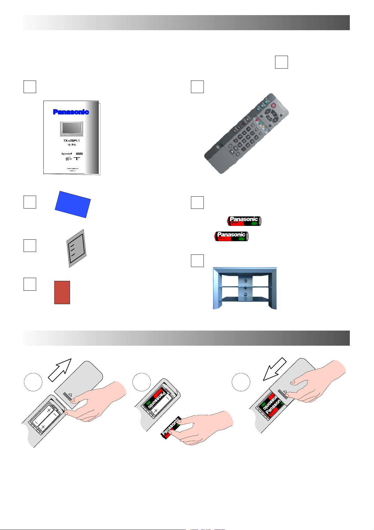
Check that you have the accessories and items shown
Operating Instruction book
TQB8E3449 --- 1
CRT Guarantee
n
Remote Control Transmitter
EUR511210
Batteries for the Remote Control Transmitter.
(2 x R6 (UM3) size)
TV Guarantee
Video cabinet
Questionnaire
INSERTING THE REMOTE CONTROL BATTERIES
1 2 3
Slide off the battery cover Insert batteries -- note correct polarity
(+ and -- )
Notes:
D Make sure that the batteries are fitted the correct way round.
D Do not mix old batteries with new batteries. Remove old, exhausted batteries immediately.
D Do not mix different battery types, i.e. Alkaline and Manganese. Do not use rechargeable (Ni-- Cad) batteries.
Replace the cover
4
Page 5

BASIC CONTROLS : FRONT PANEL AND REMOTE CONTROL
Press here and open flap to expose TV controls, front AV3 a nd headphone terminals
MAINS Power On/Off switch
Red light indicates Standby mode. Use
S t a n d b y s w i t c h , --- , + o r 0 --- 9 b u t t o n s t o
switch TV On
STR (Normalisation store)
Used to store tuning and other function settings
F (Function select)
Displays the On Screen Display functions, use repeatedly to select
from the available functions --- Volume, Contrast, Brightness, Colour,
Sharpness, Tint (in NTSC mode), Bass, Treble, Balance, Tuning mode
and Geomagnetic correction
Standby On/Off switch
Switches TV On or Off standby
Menu buttons
Press to access the Picture, Sound
and Setup menus (see page 12)
Status button
Press to display programme position,
programme name, channel number, time,
NICAM mode, aspect mode and
programme table
Teletext buttons (see page 33)
RCA Audio/Video sockets
(page 35)
S ---VHS socket (see page 35)
Headphone socket (see page 35)
TV/AV switch (see page 28)
Increases or decreases the programme position by one. When
a function is already displayed, press to increase or decrease
the selected function
Sound mute On/Off
Cursor buttons to make selections and
adjustments
Switch between viewing TV or AV input
(see page 28)
Coloured buttons used for
Programme Edit functions (see page 20)
Teletext functions (see page 33)
AV selection (see page 28)
Direct TV Record button (see page 29)
Ambience on/off
Aspect control button (see page 13)
Direct channel access
During normal TV viewing or when in the
Tuning, Programme edit or Manual tuning
menus, press and then enter channel
number using the numeric buttons
The N button will recall settings stored
with STR
STR (Normalisation store)
Programme / channel change
buttons (0- 9) and Teletext page buttons
(see page 33)
When in Standby mode, switches TV on
Programme position for selection of two digit
programmes (10 - 99) using numeric buttons
VCR / DVD buttons (see page 32)
The Help button provides a demonstration
of On Screen Display menus
5
Page 6

QUICK START GUIDE
Connection and setting up options
1. If connecting the TV using an RF cable only, proceed to option 1.
2. If connecting the TV using Scart and RF cables, proceed to option 2.
3. If connecting the TV to a Q-- Link (or Q-- Link compatible) VCR, proceed to option 3 on page 7.
4. If connecting the TV to a Q-- Link (or Q-- Link compatible) VCR and a Satellite Receiver, proceed to option 4 on page 8.
1. Connection of TV using an RF cable only
RF Connection
D Connect the RF cable into the TV Aerial socket ( ).
Aerial
Input
socket
Mains
Socket
2. Connection of TV and VCR using Scart and RF cables
Scart Connections
D TheVCRcanalsobeconnectedtotheTVusingaScartcableifyouareusingaScartequippedVCR.
D Use the TV’s AV1 Scart socket for a VCR.
D UsetheTV’sAV2SScartsocketforanS---VideoVCR.
RF Connection
D Connect the RF cable to the Aerial In socket of the VCR and an RF cable from the VCR Aerial Out socket to the
TV Aerial socket ( ).
TV
Mains
Socket
Aerial
Input
socket
AV1 and AV2
Scart sockets
Mains
Socket
VCR
AV1
Scart socket
Aerial
Input
socket
Aerial
Output
socket
Notes :
Additional equipment and cables are not supplied.
Further details of Audio/ Video co nnections can be found on pages 35 and 36.
6
Page 7
QUICK START GUIDE
What is Q-- Li nk ?
Q-- Link allows direct communication between the TV and a Q-- Link (or Q-- Link compatible) VCR, this will enable features such as
downloading of tuning information from the TV to the VCR.
When using a “NEXTVIEWLINK” VCR the main features possible are thefollowing :
D Preset Download -- Downloading of tuning information from the TV to the VCR.
D Direct TV Record -- For immediate recording of the current program (What You See Is What You Record).
When using a
D Preset Download -- Downloading of tuning information from the TV to the VCR.
D Direct TV Record -- For immediate recording of the current program (What You See Is What You Record).
D TV/VCR Auto Power On -- When the VCR plays a tape the TV will automatically switch On and select the AV2 input.
D VCR Auto Power Standby -- When the TV is switched into Standby, the VCR will also switch into Standby.
D VCR Image view On -- If the TV is in Standby mode and the VCR sends a menu to be displayed on the TV screen
This TV will also communicate with other VCR’s that bear the following logos :
D “DATA LOGIC” (a trademark of Metz Corporation).
D “Easy Link” (a trademark of Philips Corporation).
D “Megalogic” (a trademark of Grundig Corporation).
D “SMARTLINK” (a trademark of Sony Corporation).
These VCR’s may support some or all of the above functions. Refer to the VCR operating instruction book.
Further information on Q-- Link can be found on page 29.
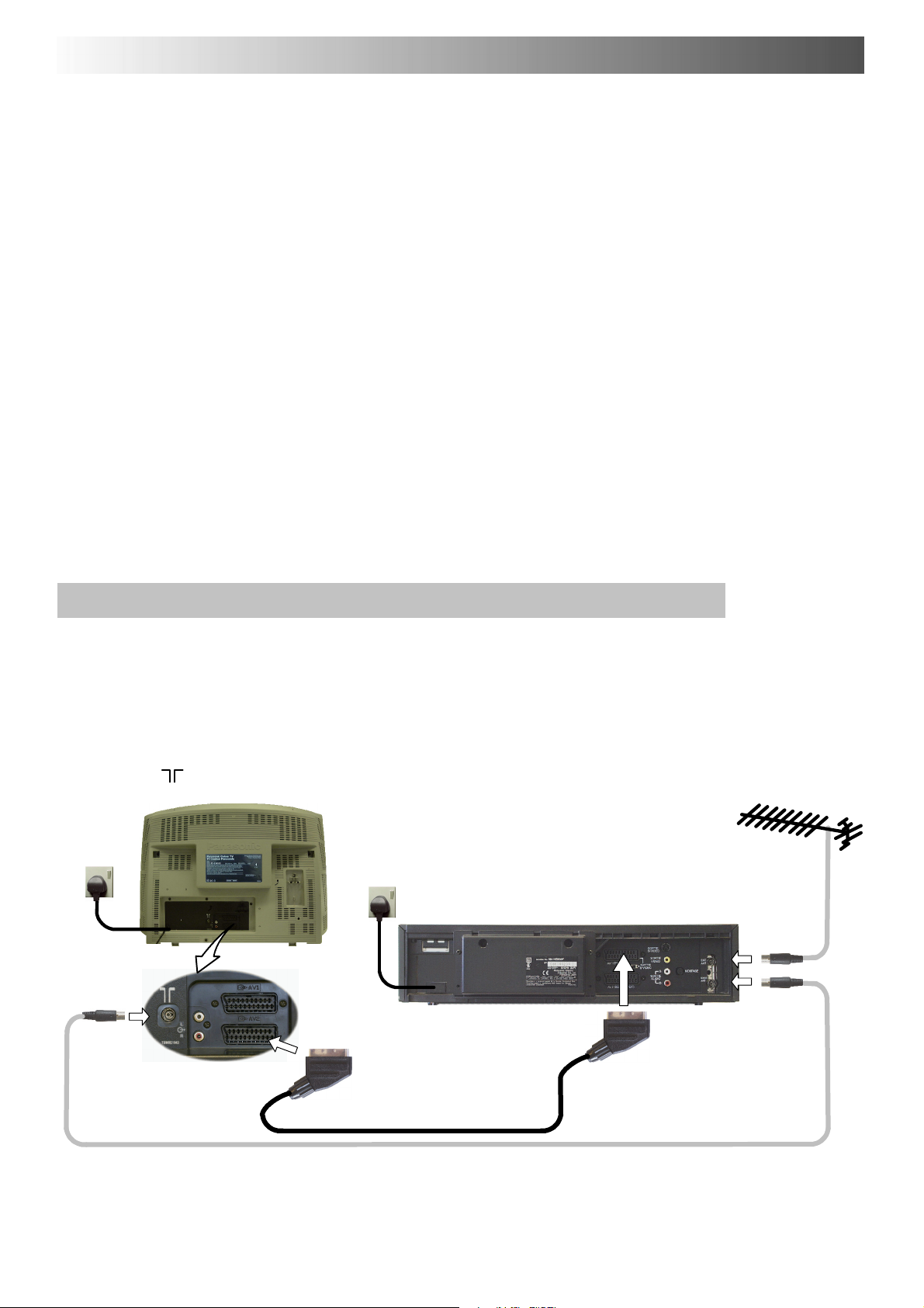
In order for Q-- Link to function correc tly, the Scart cables must be connected in a certain way, dependent on whether the TV
is being connected to a VCR (option 3, below) or to a VCR and Satellite Receiver (option 4, overleaf).
“Q-- Link” VCR the main features possible are the following :
(e.g. Main menu), the TV will automatically switch On and the menu will be displayed.
3. Q-- Link connection of TV and VCR using Scart and RF c able s
Scart Connection
D The VCR must be connected to the AV2 Scart socket of this TV using a ’fully wired’ Scart cable.
Note :
If using a
VCR, please consult your VCR operating instruction book.
“Q-- Link” VCR then the AV1 Scart of the VCR must be co nnected to the AV2 socket of the TV. If your VCR is not a “Q-- Link”
RF Connection
D Connect the RF cable to the Aerial In socket of the VCR and an RF cable from the VCR Aerial Out socket to the TV Aerial
socket ( ).
TV
Mains
Socket
Aerial
Input
socket
AV2 Scart
socket
Notes :
Additional equipment and cables are not supplied.
Further details of Audio/ Video co nnections can be found on pages 35 and 36.
Further information for VCR and Satellite Receiver installation with this TV can be found on page 31.
Mains
Socket
VCR
AV1
Scart socket
Aerial
Input
socket
Aerial
Output
socket
7
Page 8
QUICK START GUIDE
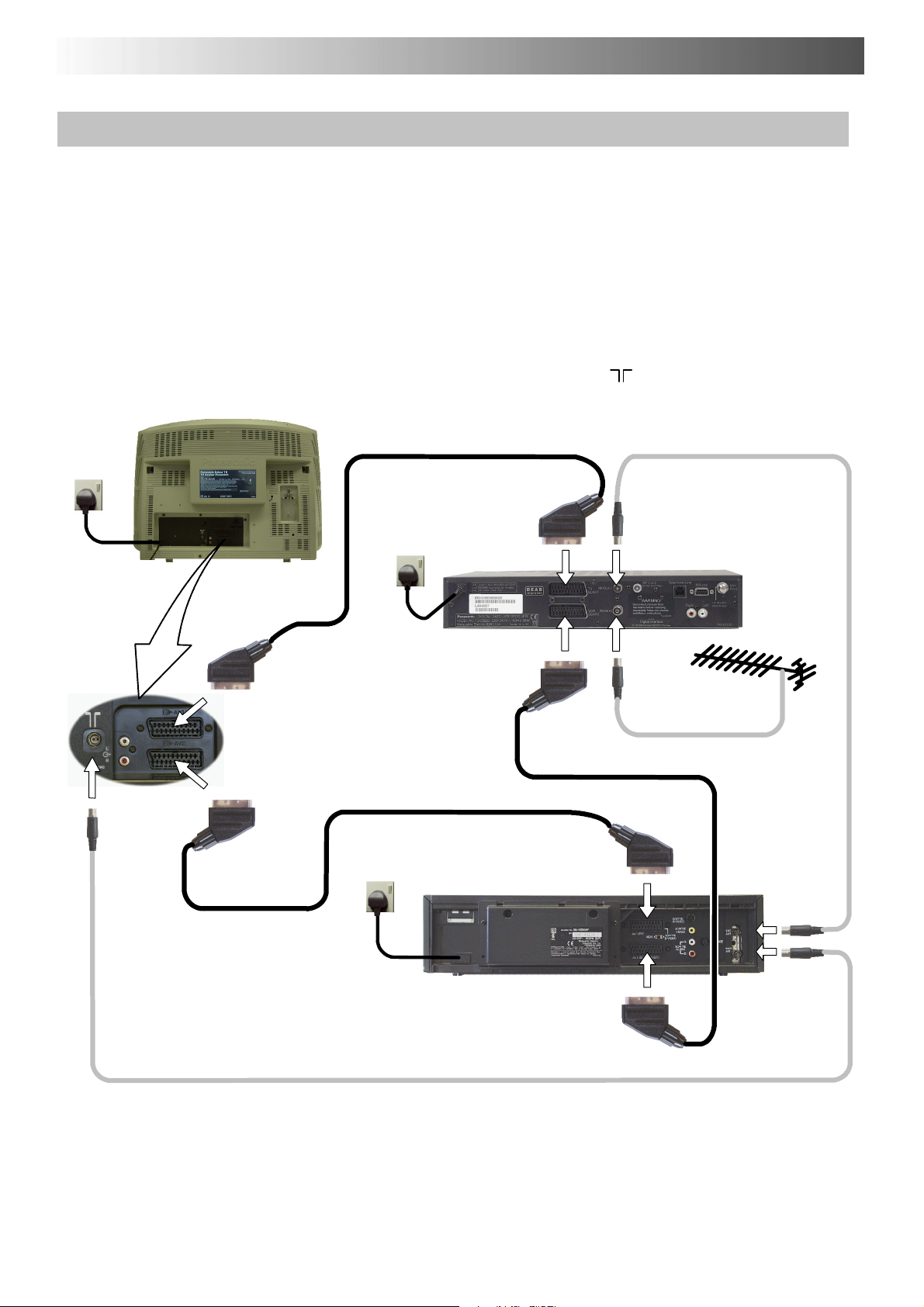
4. Q-- Link connecti on of TV, VCR and Satellite Re ceiver using Scart and RF cables
For Q-- Link to function correctly the TV, VCR and Satellite Receiver must be connected as shown in the diagram below.
Scart Connections
’Fully wired’ Scart cables should be used for all of the Scart connections.
D TheAV2ScartoftheVCRmustbeconnectedtotheVCRsocketoftheSatelliteReceiver.
D The TV Scart socket of the Satellite Receiver must be connected to the AV1 Scart socket of the TV.
Note :
If using a
VCR, please consult your VCR operating instruction book.
RF Connections
D Connect an RF cable to the Aerial In socket of the Satellite Receiver.
D Connect an RF cable from the RF Out so cket of the Satellite Receiver to the RF In socket of the VCR.
D Connect an RF cable from the RF Out socket of the VCR to the TV Aerial In socket (
Socket
“Q-- Link” VCR then the AV1 Scart of the VCR must be connected to the AV2 socket of the TV. If your VCR is not a “Q-- Link”
).
TV
Mains
Aerial
Input
socket
AV1 Scart
socket
AV2 Scart
socket
Mains
Socket
Mains
Socket
VCR
TV Scart
socket
VCR Scart
socket
AV1
Scart socket
AV2
Scart socket
Aerial
Output
socket
SATELLITE
RECEIVER
Aerial
Input
socket
Aerial
Input
socket
Aerial
Output
socket
Notes :
Additional equipment and cables are not supplied.
Further details of Audio / Video connections can be found on pages 35 and 36.
Further information for VCR and Satellite Receiver installation with this TV can be found on page 31.
8
Page 9
QUICK START GUIDE
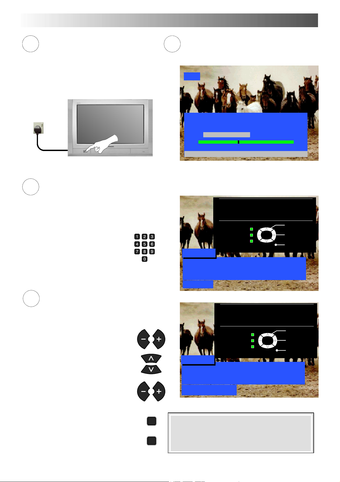
Ensure that the VCR is in Standby mode.
1
Switch ON your Satellite Receiver; to ensure
reliable tuning select either SKY ONE or SKY
NEWS (for analogue satellite receiver). Select any
channelfordigitalsatellitereceiver.
Plug the TV into mains socket and switch ON.
Mains
Socket
Owner ID
3
As an added feature, this TV has the option of adding a security code (Owner ID) and personal details into its memory,
so that in the unfortunate event of theft it will help the P olice to trace the owner.
Enter required 4 digit Owner ID
PIN NUMBER.
(using 0 to 9 on the remote control).
Programmes will appear immediately if your dealer
2
*1
has programmed the TV for you.
If the TV has not been programmed for you then Auto
setup will begin. TV stations will be located, sorted into
order and stored ready for use.
CH44
AUTO SETUP IN PROGRESS
SEARCHING : PLEASE WAIT
Stored CH44 BBC1
21 68
TV / AV : To exit
You now have the opportunity
to enter your details and
help the police crack crime
see instruction book
Owner ID
’STR’ Button -- Store Owner ID
*2
TV/AV
Change
character
Select
character
Exit
Enter NAME, HOUSE NUMBER and POSTCODE.
4
If a 4 digit PIN NUMBER was entered
above, you will be taken automaticall y to
the NAME line.
If not, move to the NAME line.
Change character.
Select character position.
Repeat above until NAME, HOUSE
NUMBER and POSTCODE are entered.
Press STR to store the details.
Press STR again, when you are asked
“A r e y ou su r e ? ”
STR
STR
PIN NUMBER : KKKK
NAME : KKKKKKKKKKKKKK
HOUSE NO : KKKKKKKKKKK
POSTCODE : KKKKKKKKKKK
0123456789
You now have the opportunity
to enter your details and
help the police crack crime
see instruction book
Change
character
Select
character
’STR’ Button -- Store Owner ID
TV/AV
Exit
Owner ID
PIN NUMBER : 1234
NAME : KKKKKKKKKKKKKK
HOUSE NO : KKKKKKKKKKK
POSTCODE : KKKKKKKKKKK
ABCDEFGHIJKLMNOPQRST
UVWXYZ+-- . 0123456789
For further information on Owner I.D., see page 27.
A space is provided on page 27 to write down the PIN
NUMBER for future reference.
9
Page 10

QUICK START GUIDE
5
TV to VCR Download
If a “Q-- Link”, “
NEXTVIEWLINK” or compatible VCR
has been connected to the AV2 socket before
starting Step 1, programme information will be
downloaded to the VCR.
Downloaded tuning information will match the
television’s.
Not all VCRs support this download of
programme information, some may require to be
started manually.
Refer to the VCR operating instruction book.
If a VCR other than those described above has
been connected, then there will be no download
operation.
TV > VCR DOWNLOAD IN PROGRESS
PLEASE WAIT
PROGRAMME : 48
REMOTE CONTROL UNAVAILABLE
BBC1
Notes :
If the VCR has not accepted download data from the TV, you may need to select the Download option from the VCR’s menu system.
Refer to the VCR operating instruction book.
If Q-- Link is not operating correctly, check the following :
D The Scart cable is connected to the TV’s AV2 Scart socket.
D The Scart cable is connected to the VCR’s compatible (Q-- Link,
NEXTVIEWLINK or similar technology) Scart socket.
D The Scart cable is a “fully wired” type.
For further information on Q-- Link and connecting equipment, see pages 29, 35 and 36.
*1. If, after Auto Setup is complete, the programme position of the digital satellite receiver is not to your preference, you can
re---arrange the programme position. Refer to the Programme edit menu --- see page 20 for details.
*2. The sorting order depends upon the TV signal, the broadcasting system, and reception conditions. If either BBC1, BBC2 or
ITV are not located, then their respective pre ---allocated programme positions (1 to 3) will remain unused.
Programme
Position
1 BBC1 BBC1 BBC1 BBC1 BBC1 BBC1 BBC1
2 BBC2 BBC2 BBC2 BBC2 BBC2 BBC2 BBC2
3 ITV ITV ITV ITV ITV ITV ITV
4 Channel 4 Channel 4 Channel 4 S4C Channel 4 Channel 5 Satellite
5 S4C S4C Satellite Satellite Channel 5 Satellite ~
6 Channel 5 Satellite ~ ~ Satellite ~ ~
7 Satellite ~ ~ ~ ~ ~ ~
Note :
~ The next available channel will appear, if no other stations are available then the Programme position will remain unused.
All stations
available
No Channel 5
No Channel 5
/S4C
No Channel 4
/ Channel 5
No S4C
No Channel 4
/S4C
No Channel 4 / S4C /
Channel 5
10
Page 11

QUICK START GUIDE
6
Slight tilting of the picture may be noticeable or coloured patches may sometimes appear at the corners of the screen
(colour purity). The Geomagnetic Correction feature can be used to eliminate them, if necessary:
First, ensure the ATP and Q --- Link download procedures are complete.
The screen should not be showing any On --- Screen Display menus.
Open the flap on the television’s front panel
Press and release here to open flap
Press the F button repeatedly until the Geomagnetic
Correction feature is displayed
F
7
Press the + or --- buttons repeatedly until the picture
appears to be level
Press the F button again to return to normal viewing.
Close the flap to prevent damage
You are now ready to begin viewing programmes
The cursor controls provide the two basic functions:
--- / v
Geomagnetic Correction
F : To exit
--,+ : Adjust tilt
F
Adjust Volume Change Programme
STR F --/v +/ TV/AV
002
11
Page 12

USING THE ON SCREEN DISPLAYS
This TV has a comprehensive system of On Screen Display menus to access
adjustments and options
Menu Title
Picture menu
TV/AV
Select
Change
Exit
Instructions
Sub-- menus
Selection bar
Some selections, for example, Contrast, Brightness, Colour and Sharpness
will allow you to increase or decrease their level.
Some selections, for example, Off timer, allow a change of setting to be made.
Some selections, for example Tuning menu, will lead to a further menu.
The PICTURE, SOUND and SET UP buttons are
used to open the main menus and also to return to
the previous menu.
The up and down cursor buttons are used to move
the cursor up and down the menus.
The left and right cursor buttons are used to access
menus, adjust levels or to select from a range of
options.
Contrast
Brightness
Colour
Sharpness
Colour balance Normal
P-- NR Off
AI On
PICTURE
SOUND
Indicator for options
SET UP
The STR button is used to store settings after
adjustments have been made or options have
been set.
The TV/AV button is used to exit the menu system
and return to the normal viewing screen.
The HELP button will run a demonstration of the
menus available. Press the HELP button and
select one of the options.
If the HELP button is pressed whilst a menu is
displayed, the ’Instructions’ box will be hidden
from view. Press the HELP button again to show
the ’Instructions’ box.
12
STR
TV/AV
HELP
?
Page 13
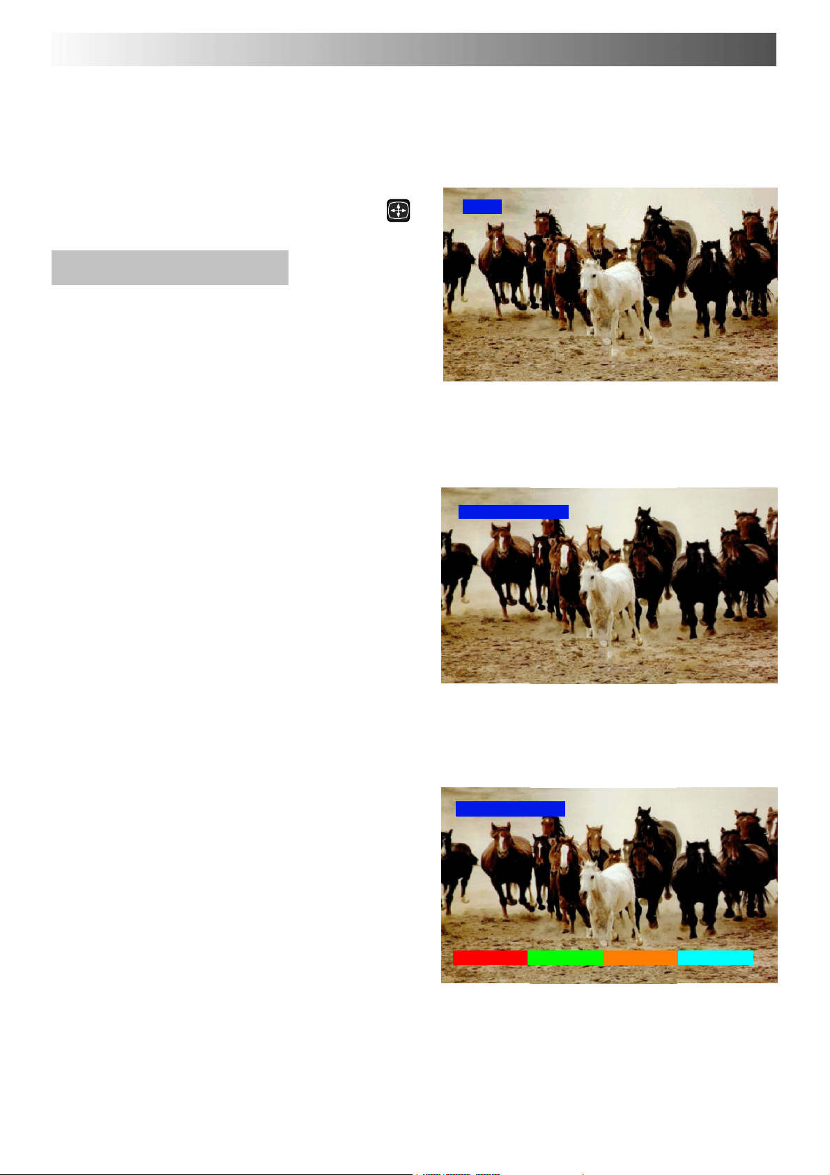
ASPECT CONTROLS
A
The widescreen TV will allow you to enjoy viewing the picture at its maximum size, including
widescreen ‘cinema format’ pictures.
Note: Just mode is not available when viewing an RGB source.
Press the ASPECT button to move through the
six aspect op t i ons : Panasonic Auto, 4:3, Zoom,
16:9 (Full), 14:9 and Just
Panasonic Auto
Panasonic Auto determines the best aspect ratio to
use to display the picture you are viewing. It does this
using a four step process to determine if the picture
being viewed is a widescreen picture.
If Panasonic Auto detects a widescreen signal it
switches into the appropriate 16:9 or 14:9 widescreen
mode. If Panasonic Auto does not detect a
widescreen signal then the picture is displayed in Just
or 4:3 mode.
The text shown on the screen indicates how
Panasonic Auto determined which ratio to use:
’WIDE’ appears in the top left of the screen if a
widescreeen identification signal (WSS) is found or a
signal found through a Scart socket. Panasonic Auto
switches to the appropriate 16:9 or 14:9 widescreen
ratio
’Panasonic Auto’ appears in the top left of the screen if
black stripes above and below the picture are
detected. Panasonic Auto chooses the best ratio and
expands the picture to fill the screen. This process can
take several minutes, depending how dark the picture
is.
’Panasonic Auto’ appears in the top left of the screen
and red and green keys at the bottom if no indication of
a widescreen signal is found, the picture is displayed
in Just or 4:3 mode. If the picture has a standard 4:3
aspect ratio then you may prefer to view itat its original
size, the red and green keys that appear allow you to
choose between viewing at standard 4:3 size or
expanded in Just mode.
Equally, you may prefer to select one of the other
modes available to view the picture.
SPECT
WIDE
’WIDE’ appears in the top left of the screen, Panasonic Auto
switches to the appropriate 16:9 or 14:9 widescreen ratio.
Panasonic Auto
’Panasonic Auto’ appears in the top left of the screen,
The best ratio is chosen and the picture expanded to fill the screen.
Panasonic Auto
Notes:
D If, in Panasonic Auto mode, you experience
problems with the screen display size when
playing back widescreen format recordings from
your VCR then it is possible that the tracking
control of your VCR requires adjustment (your
VCR instruction book will contain adjustment
details).
D The widescreen aspect ratios of different films and
programmes can vary. If these are wider than a
standard 16:9 aspect picture then a black band
may be visible at the top and bottom of the screen.
4:3 Just
’Panasonic Auto’ appears in the top left of the screen,
The picture is displayed in Just or 4:3 mode,
red and green keys appear, allowing switching between
Just and 4:3 modes.
13
Page 14
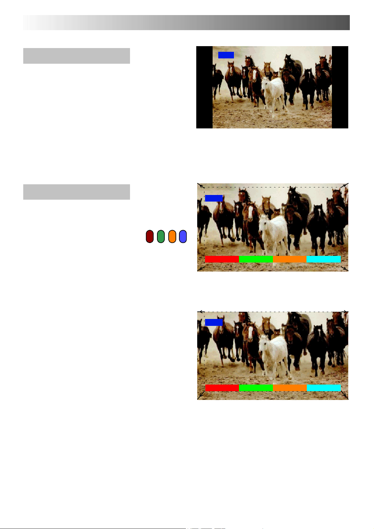
ASPECT CONTROLS
4:3
4:3 will display a 4:3 picture at its
standard 4:3 size without any
elongation.
Zoom
Zoom mode magnifies the central
section of the picture.
Thepicturecanbemovedandenlarged
vertically using the coloured keys. The
former adjustment is useful for viewing
any sub ---titles which may appear
outside the picture.
The on screen selector keys that appear
for some aspect functions will clear after
a few seconds. If you subsequently wish
to select an operation then press the
Aspect key once more for the keys to
reappear.
4:3
4:3
Zoom
V--size--V--size+ V--pos--V--pos+
Zoom
Zoom
V--size--V--size+ V--pos--V--pos+
Blue key has been pressed to move picture upwards
14
Page 15
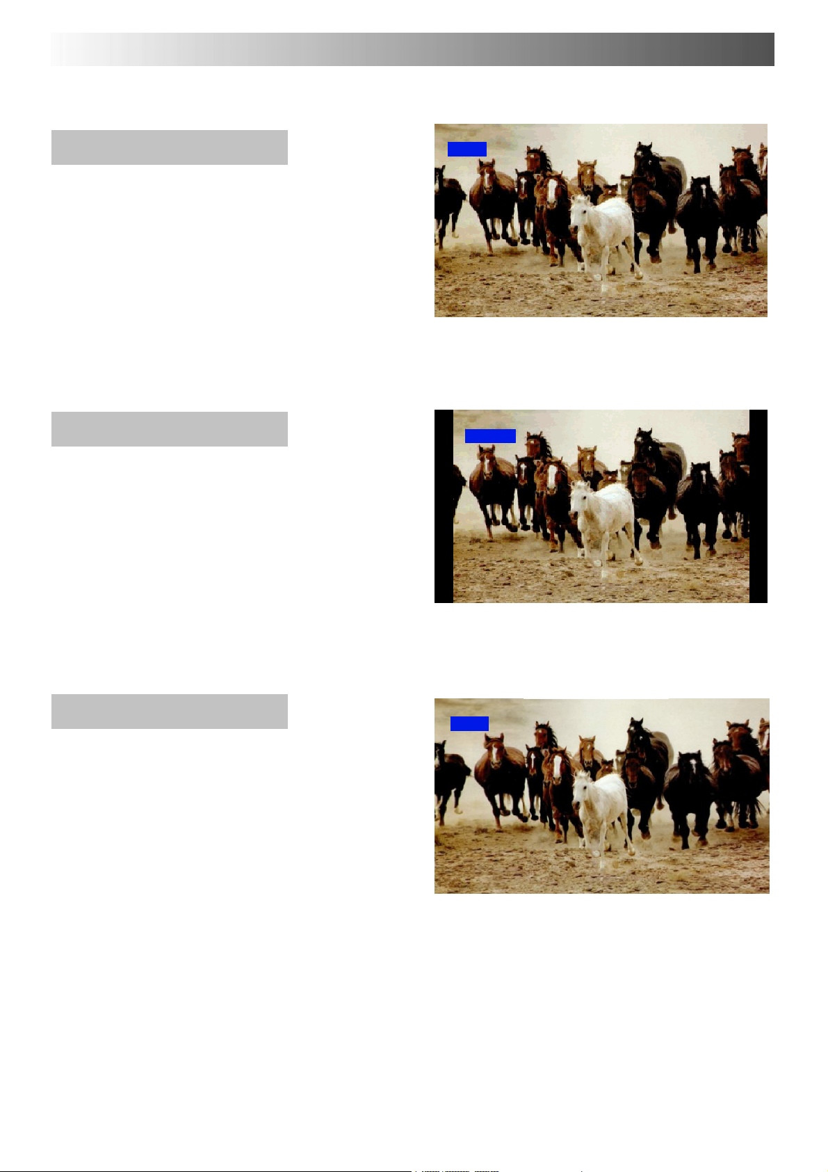
ASPECT CONTROLS
16:9 (Full)
16:9 (Full) will display the picture at its
maximum size but with slight
elongation.
14:9
14:9 will display the picture at its
maximum size without any elongation.
16:9
16:9 (Full)
14:9
Just
Just mode will display a 4:3 picture at
maximum size but with aspect
correction applied to the centre of the
screen so that elongation is only
apparent at the left and right edges of
the screen. The size of the picture will
depend on the original signal.
14:9
Just
Just
15
Page 16
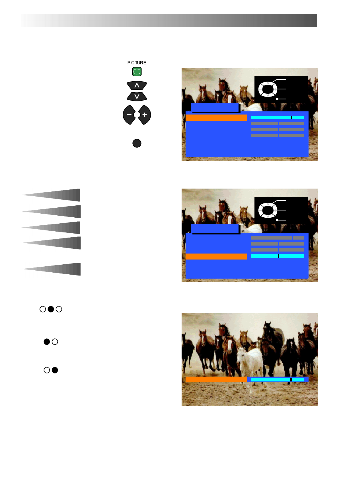
PICTURE MENU
Open the Picture menu
Move to your choice
Increase or decrease levels or
set options
Press the TV/AV button to exit
the Picture menu
TV/AV
TV/AV
Picture menu
Contrast
Brightness
Colour
Sharpness
Colour balance Normal
P-- NR Off
AI On
Select
Adjust
Exit
Contrast
Brightness
Colour
Sharpness
Tint
Colour balance
P-- NR
AI
The Contrast, Brightness, Colour and
Sharpness levels can be adjusted to suit
your own preferences.
The Tint adjustment will only appear as
a menu item if you have an NTSC signal
source connected to the TV and will
allow adjustment of the hue.
The Colour balance setting allows you
to set the overall colour tone of the
picture.
P-- NR will automatically reduce
unwanted picture noise.
AI automatically analyses the incoming
picture and processes it to give
improved contrast and optimum depth
of field.
TV/AV
Picture menu
Contrast
Brightness
Colour
Sharpness
Colour balance Normal
P-- NR Off
AI On
Sharpness
Select
Adjust
Exit
16
Page 17
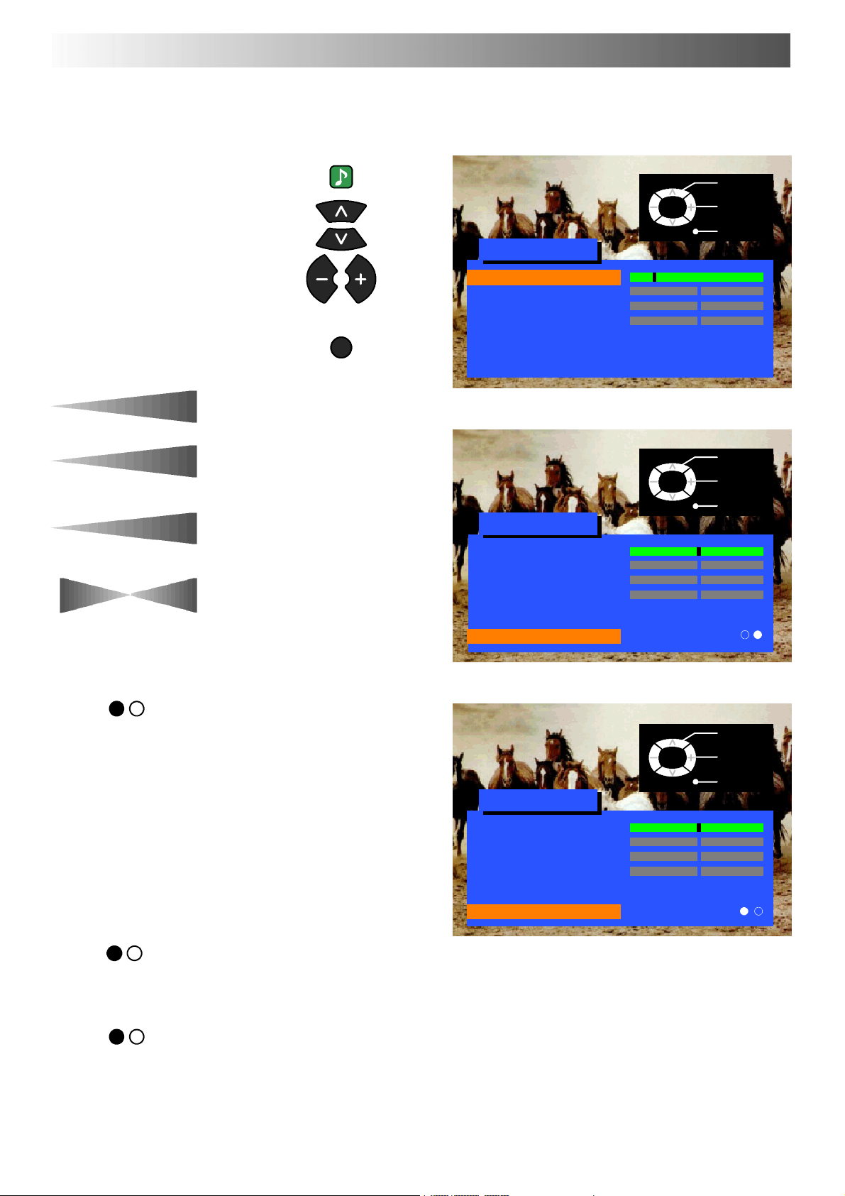
SOUND MENU
Open the Sound menu
Move to your choice
SOUND
Sound menu
TV/AV
Select
Adjust
Exit
Increase or decrease levels or
set options
Press the TV/AV button to exit
the Sound menu
Volume
Bass
Treb le
Balance
NICAM
Mode
The Volume adjustment sets the
overall output volume.
Bass adjustment will emphasise the
lower, deeper frequencies and can be
increased or decreased.
T reble adjustment will emphasise the
sharper, higher frequencies and can be
increased or decreased.
Balance affects the levels of sound
between the left and right speakers.
Adjustment can be made so that the
level from the speakers will suit your
listening position.
Select On to provide stereo sound
reproduction. Select Off for FM Mono
sound output.
If Nicam Mono is being transmitted
select either FM Mono (Off), Nicam
Mono I (M1) or Nicam Mono II (M2).
The options depend upon the signal
being transmitted.
If reception deteriorates it is advisable
to switch to FM Mono (Off).
When Nicam transmissions are not
being received the sound will be FM
Mono (Off) only.
The sound can be improved during
Music or Speech mode by selecting the
appropriate function.
TV/AV
Volume
Bass
Treble
Balance
NICAM On
Mode Music
Ambience On
Sound menu
Volume
Bass
Treble
Balance
NICAM On
Mode Music
Ambience On
Sound menu
Volume
Bass
Treble
Balance
NICAM On
Mode Music
Ambience Off
TV/AV
TV/AV
Select
Change
Exit
Select
Change
Exit
Ambience
Ambience provides a dynamic
enhancer to simulate improved spatial
effects.
17
Page 18
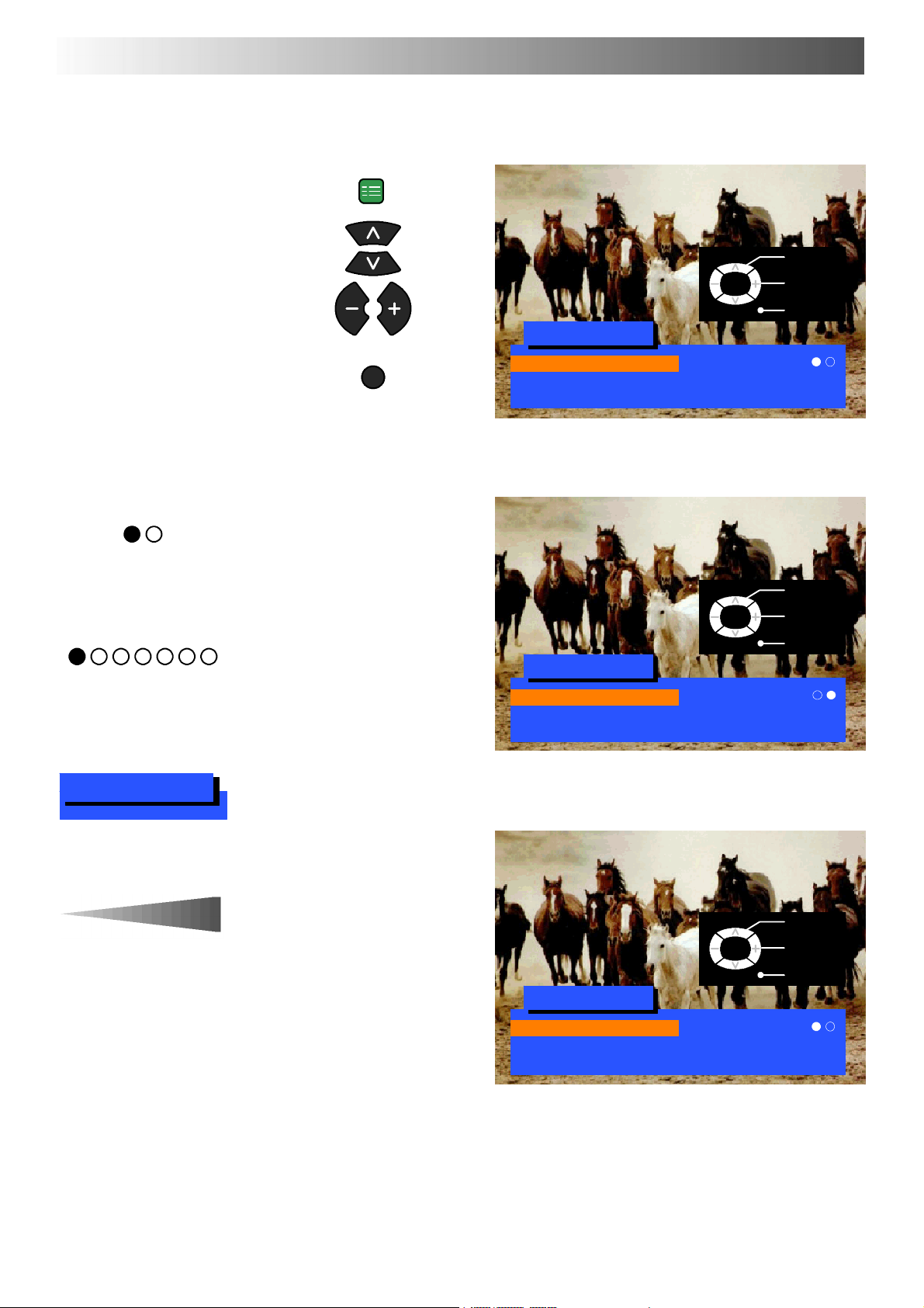
SETUP MENU
The Setup menu provides access to various advanced features and also to the T uning menu
SET UP
Open the Setup menu
Move to your choice
Increase or decrease levels, set
optionsoraccessfurthermenus
Press the TV/AV button to exit
the Setup menu
The Teletext option allows you to
Te let e x t
Off timer
choose between FASTEXT or List
mode. See page 33.
Off timer will switch the TV off within a
preset time which you can choose from
between 0 to 90 minutes in 15 minute
intervals.
TV/AV
TV/AV
Setup menu
Teletext FASTEXT
Off timer Off
Tuning menu
TV/AV
Setup menu
Teletext List
Off timer Off
Tuning menu
Select
Change
Exit
Select
Change
Exit
Tuning menu
Volume correc.
The Tuning menu provides an entry to
many other features including
Programme edit and Auto setup.
Seepage19.
Volume correction (in AV mode only)
allows you to adjust the volume level of
individual stations.
TV/AV
Setup menu
Teletext FASTEXT
Off timer Off
Tuning menu
Select
Change
Exit
18
Page 19
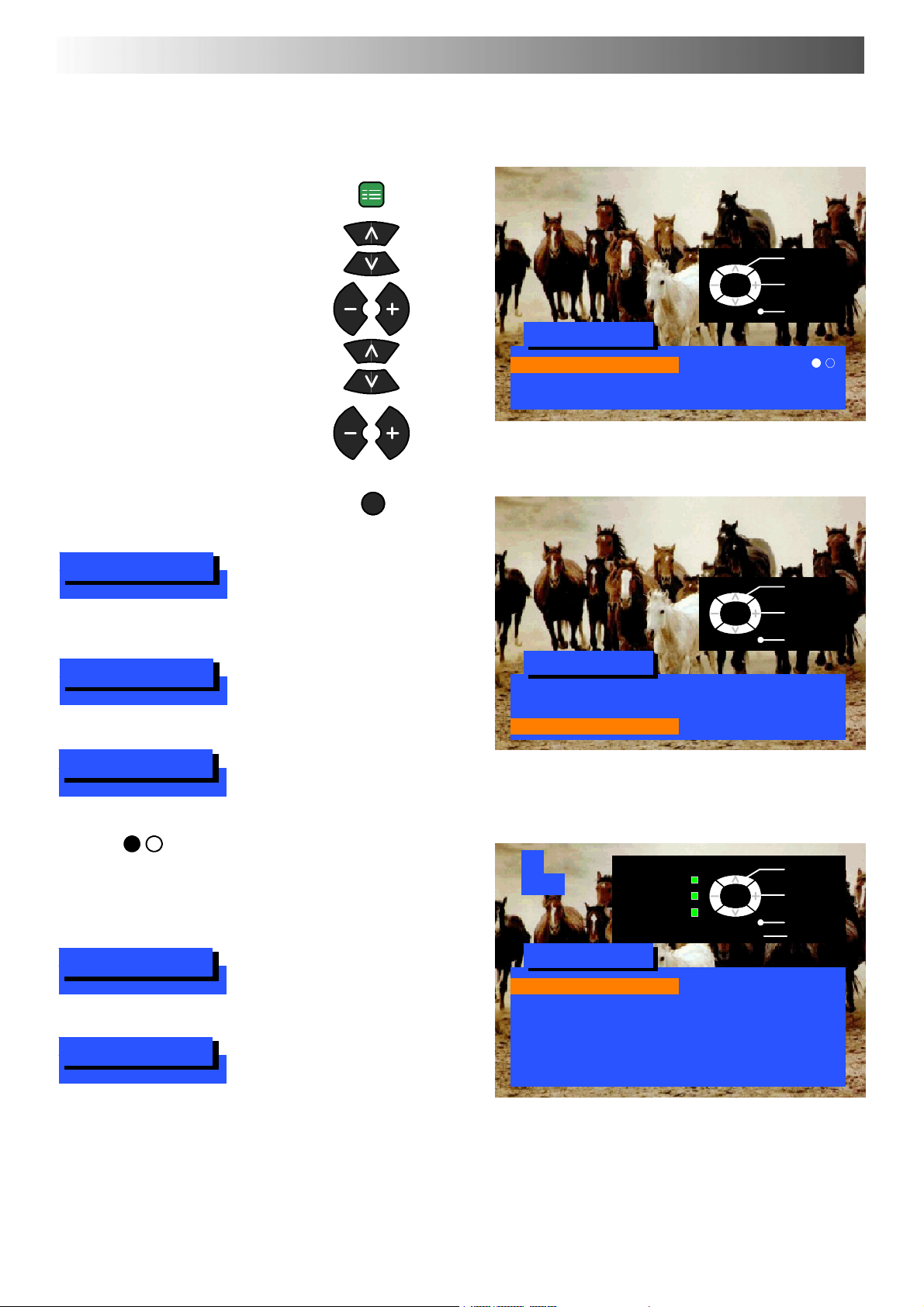
TUNING MENU -- overview
Open the Setup menu
SET UP
Move to Tuning menu
Access Tuning menu
Move to your choice
Increase or decrease levels, set
optionsoraccessfurthermenus
Press the TV/AV button to exit
Programme edit
Auto setup
Accessing the Programme edit menu
will allow stations to be moved, added,
deleted, named or locked.
Seepage20.
The Auto setup menu allows you to
automatically retune the TV.
Seepage24.
TV/AV
TV/AV
Setup menu
Teletext FASTEXT
Off timer Off
Tuning menu
TV/AV
Setup menu
Teletext FASTEXT
Off timer Off
Tuning menu Access
Select
Change
Exit
Select
Access
Exit
Manual tuning
Decoder (AV2)
Shipping condition
Owner ID
The Manual tuning menu allows
individual programme positions to be
tuned manually. See page 25.
This option is used when a decoder is
connected via AV2. Set to On if a
scrambled signal is to be processed by
the decoder. Set to Off after use.
Allows you to clear all tuning
information and reset all control levels
back to factory settings. See page 26.
Allows you to enter a security code and
address information.
Seepage27.
1
CH44
Return --
’STR’ Button Store
Tuning menu
Programme edit Access
Auto setup
Manual tuning
Decoder (AV2) Off
Shipping condition
Owner ID
TV/AV
Select
Access
Exit
19
Page 20
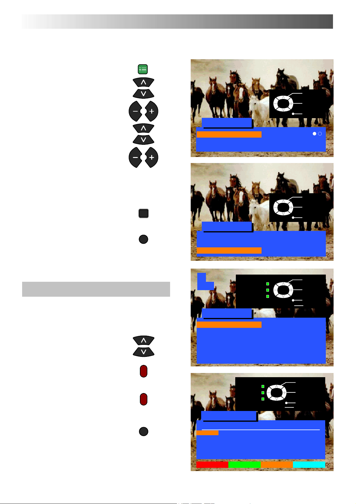
TUNING MENU -- PROGRAMME EDIT
The Programme edit menu allows you to edit the programme position settings
Open the Setup menu
Move to Tuning menu
Access Tuning menu
Move to Programme edit menu
Access Programme edit menu
Make required changes
(see sections below)
Press STR button to store
changes
If you have finished in the
Programme edit menu, press the
TV/AV button to exit
SET UP
STR
TV/AV
TV/AV
Setup menu
Teletext FASTEXT
Off timer Off
Tuning menu
TV/AV
Setup menu
Teletext FASTEXT
Off timer Off
Tuning menu Access
Select
Change
Exit
Select
Access
Exit
To delete an unwanted programme position
Ensure that the cursor is in the
Prog. Column
Choose the programme position
PresstheRedbuttononremote
control
Press the Red button ag ain to
confirm
If you have finished in the
Programme edit menu, press the
TV/AV button to exit
TV/AV
1
CH44
Return --
’STR’ Button Store
Tuning menu
Programme edit Access
Auto setup
Manual tuning
Decoder (AV2) Off
Shipping condition
Owner ID
Return --
’STR’ Button Store
Programme edit
Prog. Chan. Name Lock
1: CH44 BBC1 Off
2: CH51 BBC2 Off
3: CH41 ITV Off
4: -- -- Off
5: -- -- Off
TV/AV
TV/AV
Change
programme
Select
option
Exit
Select
Access
Exit
20
Delete Add Move TV > VCR
Page 21
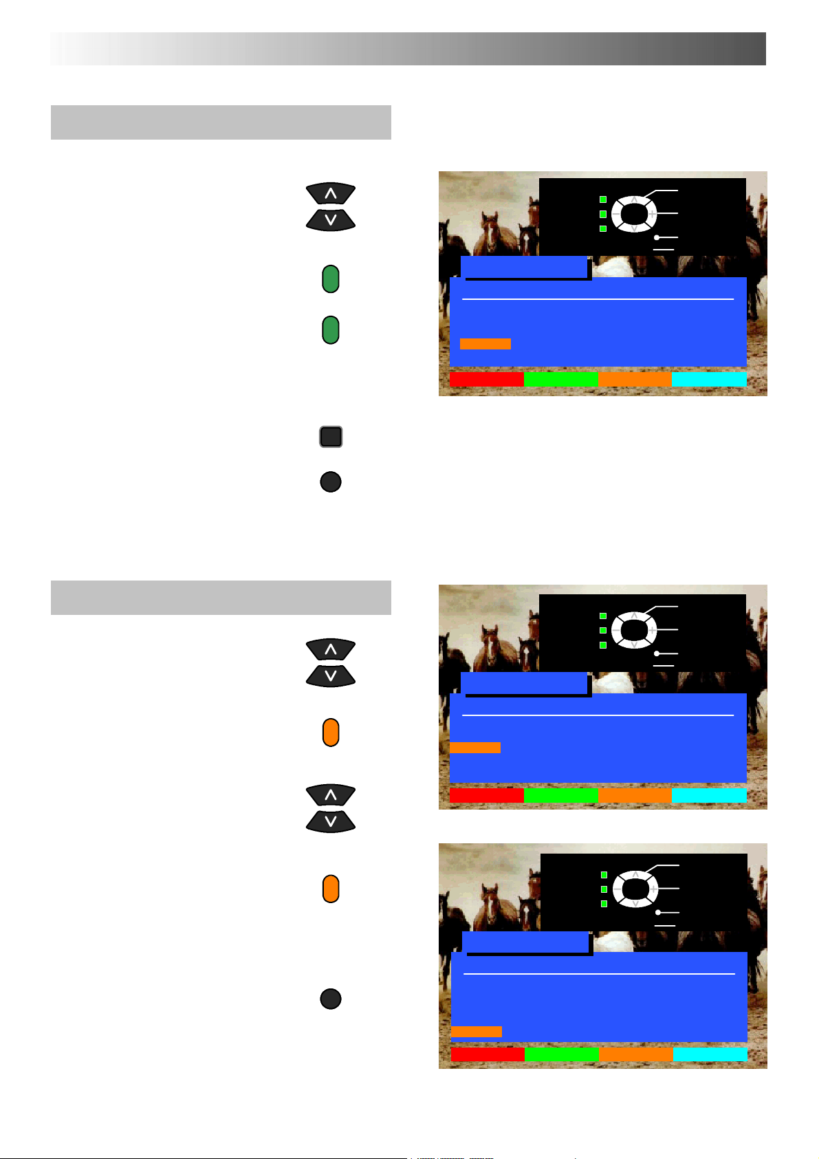
TUNING MENU -- PROGRAMME EDIT
To add a programme position
Choose the programme position
where the new programme is to be
inserted
Press the Green button
Press the Green button again to
confirm
Thisblankprogrammecanthenbe
tuned (see page 25), named (see
page 22) or locked (see page 23)
Press STR to store
If you have finished in the
Programme edit menu, press the
TV/AV button to exit
STR
TV/AV
Change
programme
Select
Return --
’STR’ Button Store
TV/AV
option
Exit
Programme edit
Prog. Chan. Name Lock
1: CH44 BBC1 Off
2: CH51 BBC2 Off
3: CH41 ITV Off
4: -- -- Off
5:
Delete Add Move TV > VCR
-- -- Off
To move a programme to another position
Choose the programme position
to be moved
Press the Yellow button on
remote control
Choose new position
Press the Yellow button again to
confirm
TV/AV
If you have finished in the
Programme edit menu, press the
TV/AV button to exit
Change
programme
Select
Return --
’STR’ Button Store
TV/AV
option
Exit
Programme edit
Prog. Chan. Name Lock
1: CH44 BBC1 Off
2: CH51 BBC2 Off
3: CH41 ITV Off
4: -- -- Off
5:
Delete Add Move TV > VCR
-- -- Off
Change
programme
Select
Return --
’STR’ Button Store
TV/AV
option
Exit
Programme edit
Prog. Chan. Name Lock
1: CH44 BBC1 Off
2: CH51 BBC2 Off
3: -- -- Off
4: -- -- Off
5: CH41 ITV Off
Delete Add Move TV > VCR
21
Page 22

TUNING MENU -- PROGRAMME EDIT
To rename a programme position
Choose the programme position
Move to the Name column
Choose the new character
Move to the next character position
Continue until renaming is done
Press STR to store
If you have finished in the
Programme edit menu, press the
TV/AV button to exit
STR
TV/AV
Change
character
Select
Return --
’STR’ Button Store
TV/AV
option
Exit
Programme edit
Prog. Chan. Name Lock
1: CH44 BBC1 Off
2: CH51 BBC2 Off
3: -- -- Off
4: CH54 C H 4 Off
5: CH41 ITV Off
ABCDEFGHIJKLM
NOPQRSTUVWXYZ
+ -- . 0123456789
22
Page 23

TUNING MENU -- PROGRAMME EDIT
To lock a programme position to prevent
access
Choose the programme position
Move to the lock column
Choose between Lock On or Lock
Off
STR
Press STR to store
Lock
On/Off
Select
Return --
’STR’ Button Store
TV/AV
option
Exit
Programme edit
Prog. Chan. Name Lock
1: CH44 BBC1 Off
2: CH51 BBC2 Off
3: -- -- Off
4: CH54 CH4 Off
5: CH41 ITV Off
If you have finished in the
Programme edit menu, press the
TV/AV button to exit
Note :
When a programme position is locked, Direct Channel
Access using the ’C’ and numeric keys on the remote
control is not available.
TV/AV
To copy programme information to a
compatible VCR connected to AV2
Move to the Prog. column
PresstheBluebuttononthe
remote control.
Programme data will now be sent
to the VCR. This might take a
while, depending on the number
of stations stored. If the message
“Unable to download, check your
VCR” appears on the screen, the
television is unable to send
programme information to the
VCR. See the VCR handbook for
further information
TV>VCR IN PROGRESS
PLEASE WAIT
Programme : 63
Remote control unavailable
If you have finished in the
Programme edit menu, press the
TV/AV button to exit
TV/AV
23
Page 24
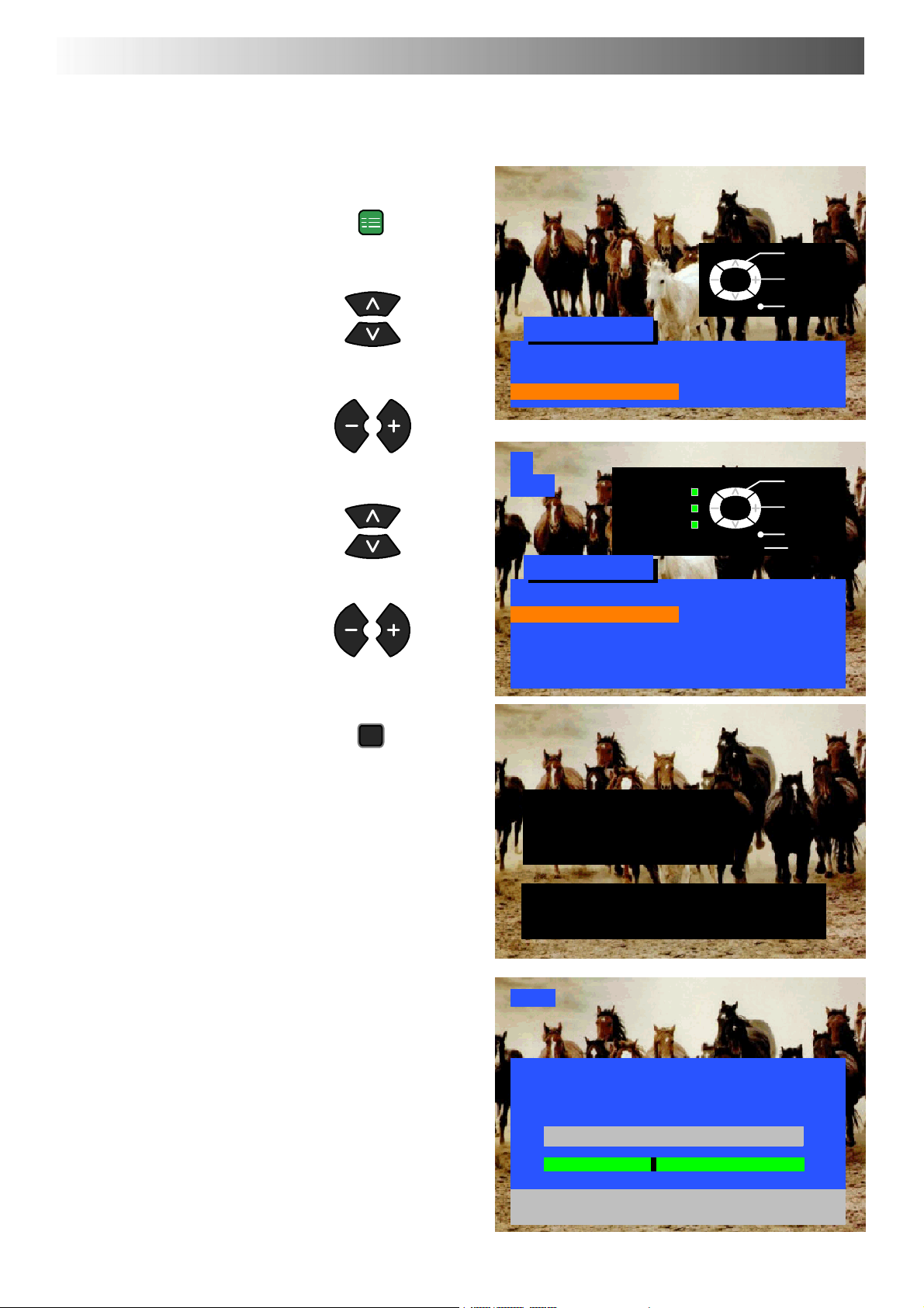
TUNING MENU -- AUTO SETUP
The Auto setup menu will allow you to automatically retune the TV to your local stations.
It is useful if you move to a different region
SET UP
Open the Setup menu
Select
Access
Move to Tuning menu
Access Tuning menu
Move to Auto setup
Access Auto setup
Press STR to start Auto setup
STR
Setup menu
Teletext FASTEXT
Off timer Off
Tuning menu Access
1
CH44
Return --
’STR’ Button Store
Tuning menu
Programme edit
Auto setup Access
Manual tuning
Decoder (AV2) Off
Shipping condition
Owner ID
TV/AV
TV/AV
Exit
Select
Access
Exit
The TV will search for, locate and
sort into order your local stations.
If a compatible VCR is connected
via the AV2 socket, programme
data will be sent to the VCR via
Q-- Link (see page 29)
Once this operation is completed
the TV will display programme
position 1
WARNING
All current tuning
data will be erased
STR : Start Auto setup
TV/AV : To exit
SETUP : Return to tuning menu
CH44
AUTO SETUP IN PROGRESS
SEARCHING : PLEASE WAIT
Stored CH44 BBC1
21 68
SETUP : Return to tuning menu
TV/AV : To exit
24
Page 25
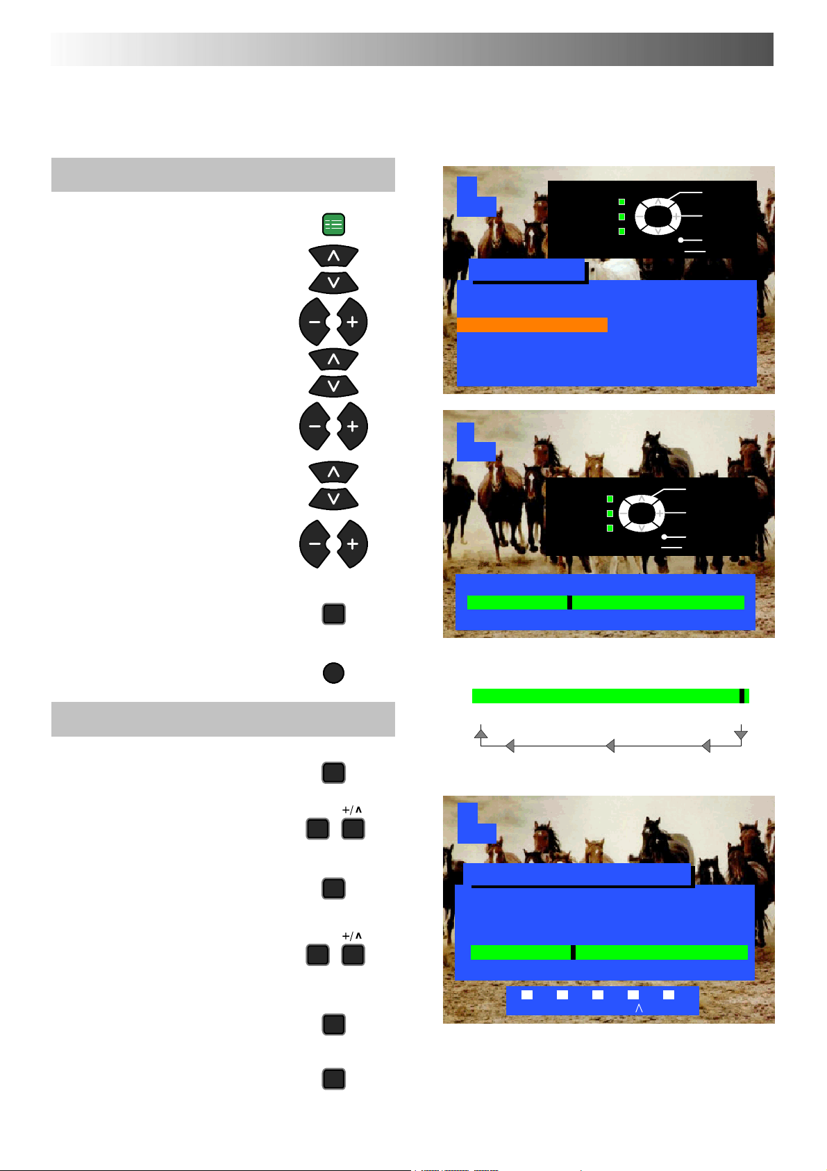
TUNING MENU -- MANUAL TUNING
Manual tuning of the programme positions is available either from the On Screen Display menu
or from the front panel controls
Manual tuning menu
Open the Setup menu
Move to Tuning menu
Access Tuning menu
Move to Manual tuning
Access Manual tuning
Select the programme position to
be tuned
Press repeatedly until required
station is found
SET UP
1
CH44
Return --
’STR’ Button Store
Tuning menu
Programme edit
Auto setup
Manual tuning Access
Decoder (AV2) Off
Shipping condition
Owner ID
1
CH44
Return --
’STR’ Button Store
TV/AV
TV/AV
Select
Access
Exit
Programme
down/up
Search
down/up
Exit
When the desired station is found,
press STR to store.
The programme position will flash
Press the TV/AV button to exit
Manual tuning (Front panel)
Press the F button (Front panel)
until “Tuning mode” is reached
Press the -- or + button to access
Tuning mode
Press the TV/AV button to move
between “Change programme” and
“Search”
Press the -- or + button to change
programme position or start search
When the desired station is found,
press STR to store.
The programme position will flash
STR
TV/AV
-- /v
TV/AV
-- /v
STR
Manual tuning
21 68
Important note :
On passing channel 68, tuning will restart at channel 21.
21 68
F
1
CH44
Manual tuning (Front panel)
-- ,+ : Search
TV/AV : Move cursor
STR : To store
F : To exit
21 68
STR F -- /V +/ TV/AV
Repeat above procedure to tune
additional programmes or press the
F button to exit
F
25
Page 26
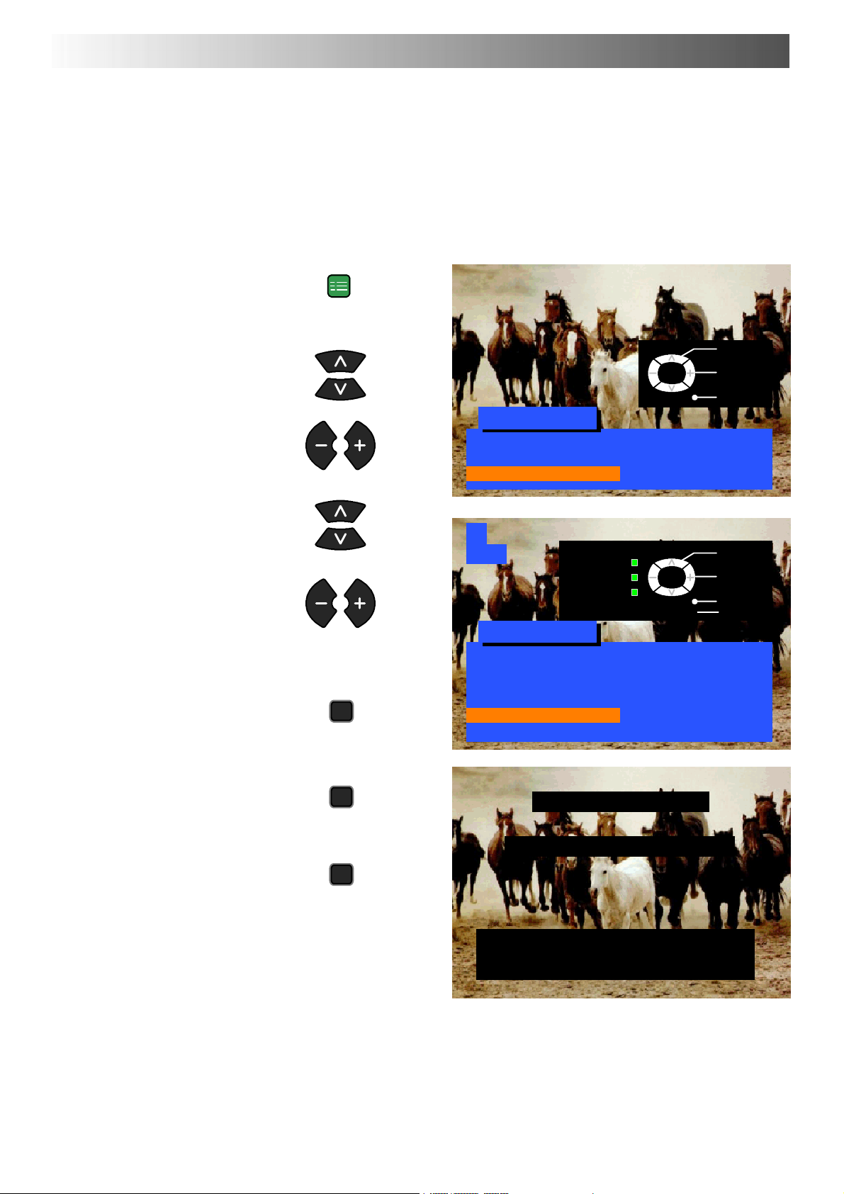
TUNING MENU -- SHIPPING CONDITION
Shipping condition allows you to reset the TV to its original condition, i.e. no channels tuned in
This is useful, for example, if you move to a different area when you will probably want the TV to tune itself to your new local stations.
ThiscanbedoneeitherthroughtheShipping condition menu or through the Auto setup menu.
The Shipping condition menu will reset all data, clearing all tuning information and resetting all control levels back to factory settings.
Y o u may need to adjust your VCR or programme position ‘0’ VCR after operating the Shipping condition menu -- refer to page 31.
Open the Setup menu
Move to Tuning menu
Access Tuning menu
Move to Shipping condition
Access Shipping condition
Press STR to start
SET UP
STR
Setup menu
Teletext FASTEXT
Off timer Off
Tuning menu Access
1
CH44
Return --
’STR’ Button Store
Tuning menu
Programme edit
Auto setup
Manual tuning
Decoder (AV2) Off
Shipping condition Access
Owner ID
TV/AV
TV/AV
Select
Access
Exit
Select
Access
Exit
Pressagain,toconfirm,each
time that you are asked, “Are
you sure ?”
Switch TV off and wait for a few
seconds.
Switch TV on again.
Auto setup will begin, stations
will be located, sorted and
stored ready for use.
Seepage24
26
STR
Shipping condition
All tuning data will be erased
STR
STR : Start
TV/AV : To exit
SETUP : Return to tuning menu
Page 27
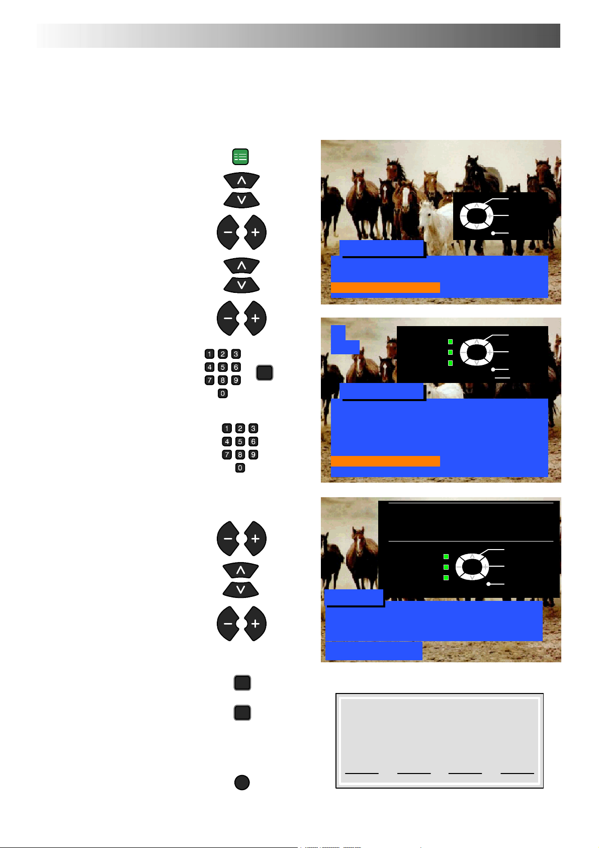
TUNING MENU -- OWNER I.D.
Owner I.D. allows you to enter a security code and address information so that in the unfortunate
event of theft it will help the Police to determine the owner.
If the Owner I.D. information was not entered after Auto setup or it is necessary to alter some of the I.D.
information it can be re-- accessed via the Tuning menu.
Open the Setup menu
Move to Tuning menu
Access Tuning menu
Move to Owner I.D.
Access Owner I.D.
SET UP
TV/AV
Setup menu
Teletext FASTEXT
Off timer Off
Tuning menu Access
Select
Access
Exit
If the Owner I.D. has previously
been set, enter the PIN NUMBER
(using 0 to 9 on the remote control)
followed by STR to proceed, this
will take you to the NAME option.
If no Owner I.D. has previously
been set, enter the required 4 digit
Owner I.D. PIN NUMBER (using 0
to 9 on the remote control).
If a 4 digit PIN NUMBER was
entered above, you will be taken
automatically to the NAME line.
If not, move to the NAME line.
Change character.
Select character position.
Repeat above until NAME, HOUSE
NUMBER and POSTCODE are
entered.
Press STR to store the details.
Press again, to confirm,when
asked, “Are you sure ?”
The Tuning menu will be
displayed.
STR
STR
STR
1
CH44
Return --
’STR’ Button Store
TV/AV
Tuning menu
Programme edit
Auto setup
Manual tuning
Decoder (AV2) Off
Shipping condition
Owner ID Access
You now have the opportunity
to enter your details and
help the police crack crime
see instruction book
Owner ID
PIN NUMBER : 1234
NAME : KKKKKKKKKKKKKK
HOUSE NO : KKKKKKKKKKK
POSTCODE : KKKKKKKKKKK
ABCDEFGHIJKLMNOPQRST
UVWXYZ+-- . 0123456789
’STR’ Button -- Store Owner ID
TV/AV
For future reference,
write your PIN Number here :
Select
Access
Exit
Change
character
Select
character
Exit
Press the TV/AV button to exit
TV/AV
27
Page 28
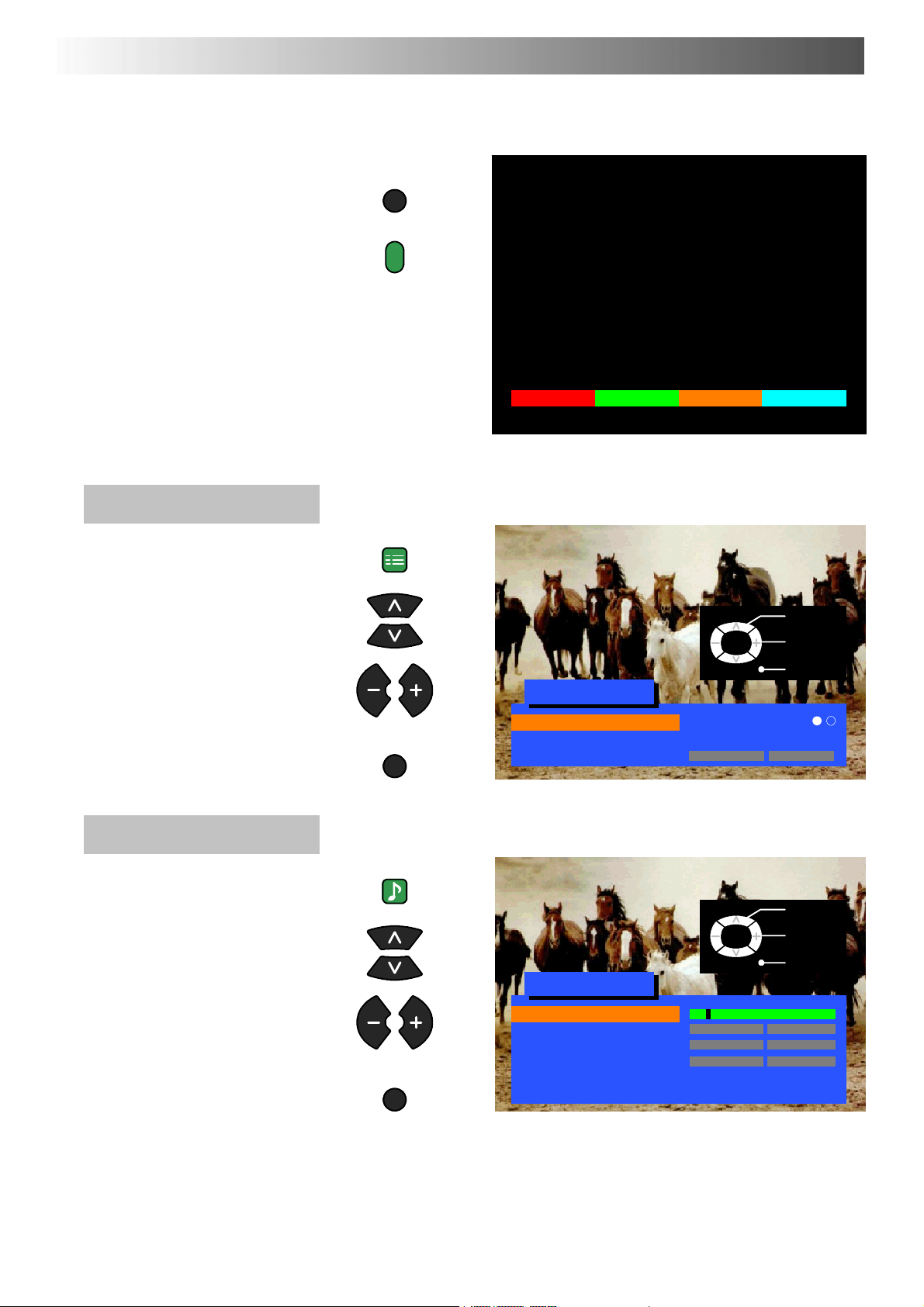
AV SELECT AND SETUP
The AV Select menu will allow you to choose which AV source to view
Press the TV/AV button
Press the appropriate coloured
remote control button(whilst the
options remain on screen)
The options will disappear
You may wish to make adjustments
in the Setup or Sound menus
Setup menu
Open the Setup menu
Move to your choice
TV/AV
SET UP
AV1
AV1 AV2/S AV3/S
Select
Change
Access adjustments or options
Press the TV/AV button to exit
Sound menu
Open the Sound menu
Move to your choice
Access adjustments or options
Press the TV/AV button to exit
TV/AV
SOUND
TV/AV
TV/AV
Setup menu
Teletext FASTEXT
Off timer Off
Volume correc.
TV/AV
Sound menu
Volume
Bass
Treble
Balance
Mode Music
Ambience Off
Exit
Select
Adjust
Exit
28
Page 29

Q-- LINK
Q-- Link allows the television to communicate with a compatible VCR
For Q-- Link communication to work,the TVmust be connected toa VCR with the “Q-- Lin k”, “NEXTVI E WL I N K ”, “DATALOGIC ”, “Easy
Link”, “Megalogic” or “SMARTLI N K ” logo using a ’fully wired’ Scart cable between the AV2 socket of the television and the
appropriat e socket on your VCR.
For connection to the appropriate Scart socket on the VCR, refer to the VCR operating instruction book.
When using a “
D Preset Download -- Downloading of tuning information from the TV to the VCR .
D Direct TV Record -- For immediate recording of the current program (What Y ou See Is What You Record).
When using a “Q-- Link” VCR the main features possible are the following :
D Preset Download -- Downloading of tuning information from the TV to the VCR .
D Direct TV Record -- For immediate recording of the current program (What Y ou See Is What You Record).
D TV/VCR Auto Power On -- When the VCR plays a tape the TV will automatically switch On and select the AV2 input.
D VCR Auto Power Standby -- When the TV is switched into Standby, the VCR will also switch into Standby.
D VCR Image view -- When the VCR plays a tape the TV will automatically switch On and select the AV2 input.
This TV will also communicate with other VCR’s that bear the following logos :
D “DATA LOGIC” (a trademark of Metz Corporation).
D “Easy Link” (a trademark of Philips Corporation).
D “Megalogic” (a trademark of Grundig Corporation).
D “SMARTLINK” (a trademark of Sony Corporation).
These VCR’s may support some or all of the above functions.
Refer to the VCR operating instruction book.
NEXTVIEWLINK” VCR the main features possible are the following :
Preset Download
This allows the programme order from the TV to be downloaded to the VCR, this helps to ensure that correct recordings are made, there
are several ways to perform this operation :
1. During installation as explained in the ’Quick Start Guide’ beginning on page 6.
2. When Auto setup is started from within the Tuning menu, see page 24.
3. When TV to VCR manual download is started from within ’Programme edit’, see page 23.
4. Preset download started from the VCR, refer to the VCR operating instruction book.
Important Note:
Not all VCRs support this type of data communication system. Some may support certain features, but not others. Refer to the VCR
operating instruction book.
If Q-- Link is inoperative, first confirm that your Scart cable is a full function type. Ask your dealer for further details.
29
Page 30

Q-- LINK
What You See Is What You Record (DIRECT TV RECORDING)
This will allow the immediate recording of the program currently shown on the T elevision.
DIRECT
TV REC
Press the DIRECT TV REC button on the remote control
If the VCR is in Standby mode with a useable tape inserted, it will automatically switch on when you press the DIRECT TV REC button.
If a “Q-- Link” VCR is connected a message will appear on the TV screen showing what is being recorded, or if it is not possible to record.
Some “Q-- Link” compatible VCR’s will only display the message when on the VCR programme position(0) or in AV mode. Refer to the
VCR operating instruction book.
VCR recording preset prog VCR recording TV source
Recording this programme now
VCR is recording the programme signal from its
owntuner.IfyouwishyoucanswitchofftheTV
and leave the VCR recording in the normal way.
VCR is reco rding the programme signal from the television.
Y ou must not change programme position or switch off the TV: if
you do, the VCR will automatically stop recording and switch off.
No recording -- TAPE IS PROTECTED
The write protection tab on the back of the cassette
has been removed.
Examples of other messages that might be displayed are:
No recording -- NO TAPE
No recording -- VCR IS PLAYING
VCR Recording VCR external
No recording -- ALREADY RECORDING!
No recording -- TAPE MAY BE DAMAGED
No recording -- NO SOURCE AVAILABLE
TV / VCR Auto Power On
(With a Panasonic Q-- Link VCR connected, this additional feature is available).
D If you insert a tape in the VCR and press the Play button whilst the TV is in ’Standby’ mode, the TV will automatically switch On
and select the AV2 input so that you can view the tape.
Some other VCR’s may support this feature. Refer to the VCR operating instruct ion book.
VCR Auto Power Standby
(With a Panasonic Q-- Link VCR connected, this additional feature is available).
When the TV is switched into ’Standby’ mode, the VCR will also switch into ’Standby’ mode if there is no tape in the VCR, or
ifthereisatapeinandtheVCRisin’Rewind’or’Stop’mode(iftheVCR is rewinding a tape, it will not switch into ’Standby’ mode until
rewinding has finished).
Some other VCR’s may support this feature. Refer to the VCR operating instruct ion book.
VCR Image View On
(With a Panasonic Q-- Link VCR connected, this additional feature is available).
If the TV is in Standby mode and the VCR sends a menu to be displayed on the TV screen (e.g. Main menu), the TV will automatically
switch On and the menu will be displayed.
Some other VCR’s may support this feature. Refer to the VCR operating instruct ion book.
30
Page 31
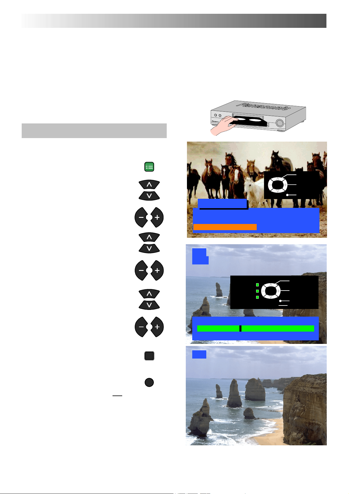
VCR AND SATELLITE RECEIVER INSTALLATION
Your new TV is supplied with programme position ‘0’ set to receive an RF signal from your VCR, although a Scart connection is
preferable if the VCR is so equipped.
However, if for so me reason your VCR is tuned to a different RF channel then you will not receive any picture or sound from your VCR
on programme position ‘0’ of the TV. It will be necessary to either adjust the RF channel of your VCR (some VCR’s allow adjustment of
their RF channel via their remote control unit) or to adjust the tuning of the TV’s programme position ‘0’ or both until it receives the RF
output channel of your VCR.
It is intended that this advice is used in conjunction with the instruction books for your additional equipment.
Use the AV1 Scart terminal for a VCR.
Use the AV2S Scart terminal for an S-- Video VCR.
Use the AV2S Scart terminal for a Q-- Link,
To tune your TV to the VCR
Switch on the VCR, insert and play a
pre-- recorded tape with known content
Open the Setup menu
Move to Tuning menu
Access Tuning menu
Move to Manual tuning
Access Manual tuning
Select programme position ‘0’ VCR
NEXTVIEWLINK or compatible VCR.
SET UP
Setup menu
Teletext FASTEXT
Off timer Off
Tuning menu Access
VCR
CH32
Return --
’STR’ Button Store
TV/AV
TV/AV
Select
Access
Exit
Programme
down/up
Search
down/up
Exit
Start searching for the VCR playback
of the known content tape
When the VCR playback is found,
STR
press STR to store
TV/AV
Press the TV/AV button to exit
See below for installation of VCR and
Satellite
Receiver
Notes :
D If picture patterning occurs on programme position ‘0’ it
may be necessary to adjust the RF output channel of
the VCR, refer to the VCR instruction book.
D If a Satellite Receiver and a VCR are going to be used
with RF cable connections it is important to avoid both
units being set on the same channel.
Refer to the Satellite Receiver and VCR instruction
books for precise tuning information.
Manual tuning
21 68
VCR
31
Page 32
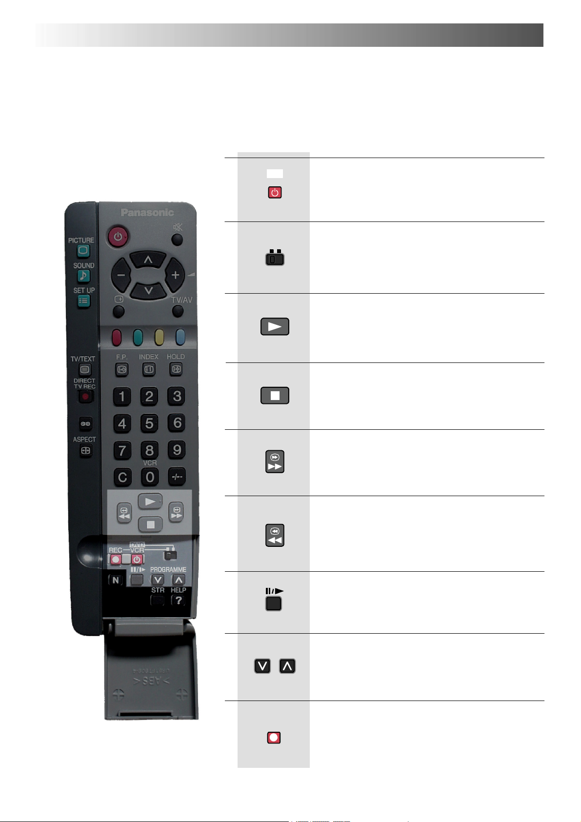
VCR / DVD OPERATION
The Remote Control is capable of operating some functions of selected Panasonic VCRs and DVD (Digital Versatile Disc) equipment.
Some VCR and DVD equipment have different functions, so to ensure compatibility please refer to the equipment’s instruction book or
consult your dealer for details.
DVD
VCR
Standby
Press to switch the VCR or DVD to standby mode.
Press again to switch back on.
VCR / DVD switch
Use this switch to select whether controls operate
DVD equipment or your VCR.
Play
Press to playback the tape or DVD.
Stop
Press to stop the tape or DVD.
Skip/FastForward/Cue
VCR: Press to fast forward the tape. In Play mode, press
to view the picture rapidly forward (Cue).
DVD: Press once to skip to the next track. In play mode
press and hold to view the picture rapidly forward.
REC
Skip / Rewind / Review
VCR: Press to rewind the tape. In Play mode, press to
view the picture rapidly in reverse (Review).
DVD: Press once to skip to the previous track. In play
mode press and hold to view the picture rapidly in
reverse.
Pause / Still
Press in playback mode, the picture will pause.
Press again to restart play.
Programme Up / Down
Press to increase or decrease the VCR programme
position by one.
Record
Press this button to start recording.
32
Page 33
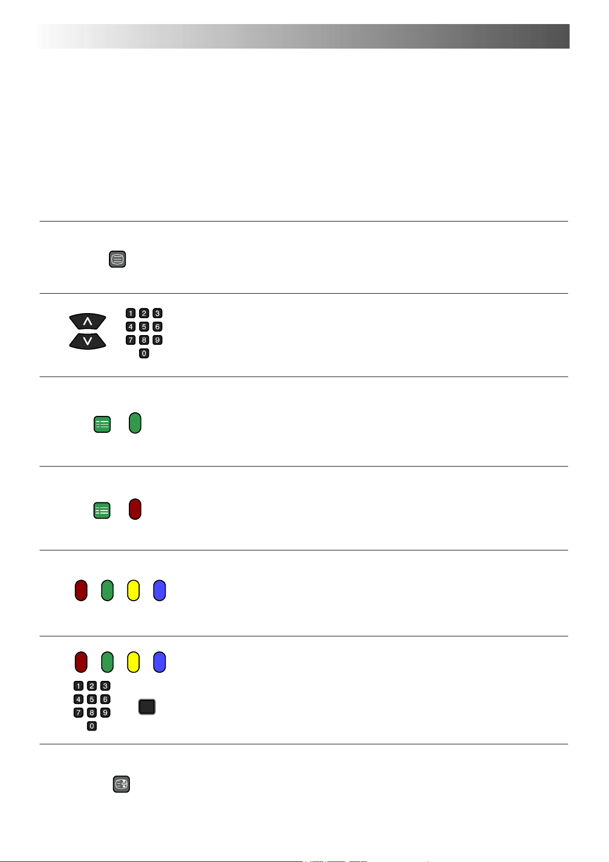
TELETEXT OPERATION
D Teletext features may vary depending on the Broadcast ing Companies and is only available if the channel selected is transmitting
Tel e tex t .
D Pressing the Picture button whilst in Teletext operation will display the contrast function with a cyan bar,press A"to alter the setting
as required.
Pressing the Setup button whilst in Teletext operation will display special function options at the bottom of the screen.
D When in Teletext mode, the volume may still be altered to the desired listening level.
What is LIST mode ?
In LIST mode, four differently coloured page numbers are situated at the bottom of the screen. Each of these numbers can be altered and
stored in the TV’s memory.
What is FASTEXT?
In FASTEXT mode, four differently coloured subjects are situated at the bottom of the display. To access more information about one of
these subjects, press the appropriately coloured button. This facility enables fast access to information on the subjects shown.
TV/TEXT
SET UP
SET UP
TV / Teletext mode
Press the TV/TEXT button.
The screen will display the Teletext page.
Press again when you wish to return to TV. mode.
Page Selection
Pages can be selected in two ways :
a. Press the Up / Down buttons to increase or decrease the page number by one.
b. By entering the page number, using 0 -- 9 on the remote control.
Full/Top/Bottom
Press the SET UP button to display special functions, followed by the Green button.
Press the Green button again to expand the BOTTOM half.
Press again to return to normal (FULL) size.
Reveal
Press the SET UP button to display special functions, followed by the Red button to
reveal hidden words e.g. quiz page answers. Press again to hide.
HOLD
STR
Red / Green / Yellow / Blue buttons
In FASTEXT mode these correspond to the differently coloured subjects.
In LIST mode they correspond to the differently coloured page numbers.
List Store
In LIST mode the four page numbers can be altered (programme positions 1 -- 25 only).
To do this, press one of the four coloured butto ns and enter the new page number.
Press and hold STR, the page numbers will change to white indicating that the page is
stored.
Hold
To hold the Teletext page when viewing multi-- page information.
Press again to return to automatic page update.
33
Page 34
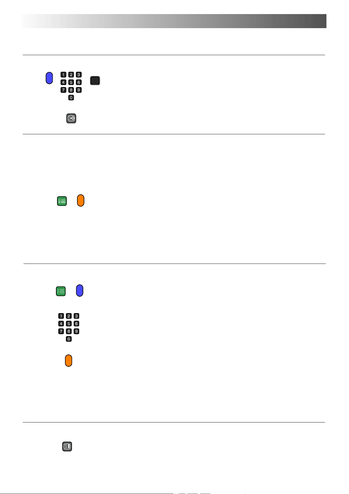
TELETEXT OPERATION
It is not possible to change the programme position when in News flash, Update or Sub Coded Page Access operation.
SET UP
F. P.
STR
FavouritePage(F.P.)
Stores a favourite page in memory for instant recall. To store such a page, the TV must
be in LIST mode, and the programme position must be from 1 -- 25.
Press the Blue button, select the page number, then press and hold the STR button.
The page number is now stored.
Press F. P. to recall this page.
Update Display
Press the SET UP button to display special functions, followed by the Yellow button to
view the TV picture whilst searching for a Teletext page.
When found, the screen will display the page number at the top left.
Press the Yellow button to view the page.
Press TV / TEXT again to return to normal TV operation.
News Flash
When a news flash page has been selected, press SET UP, Yellow,toviewtheTV
picture. When an update is received, the page number will be displayed on screen.
Press the Yellow button to display the News Flash
Press TV / TEXT to return to normal TV. operation.
Update
Press SET UP, Yellow to see the update of information on certain pages.
When an update is received, the page number will be displayed at the top left of the
screen.
Press the Yellow button to view the page.
Press TV / TEXT to return to normal TV. operation.
SET UP
INDEX
Sub Coded Page Access
When Teletext information exceeds more than one page, it may take some time for the
automatic changing of the sub pages to reach the sub page you require.
It is possible to enter your required sub page and continue watching the normal
programme until the correct sub page is found.
Select the required page number using buttons 0 -- 9.
Press the SET UP button followed by the Blue button; T**** will be displayed at the top
right of the screen.
Enter desired sub page number before the T**** disappears.
To select page 6 enter 0, 0, 0 and 6.
(If in LIST mode, a ‘T’ will appear in the current box at the bottom).
Press the Yellow button to view a normal TV programme.
(Press SET UP, Yellow in LIST mode).
Whenthepageisavailable,presstheYellow button to view the page.
To clear the page perform one of the following :
D Press SET UP.
D Select a new page number.
D Press TV/TEXT to return to normal TV operation.
Index
When in FASTEXT operation
Press INDEX to return to the main index page.
Depending on the way information is transmitted, this may have to be pressed more than
once to return to the main index page.
34
Page 35
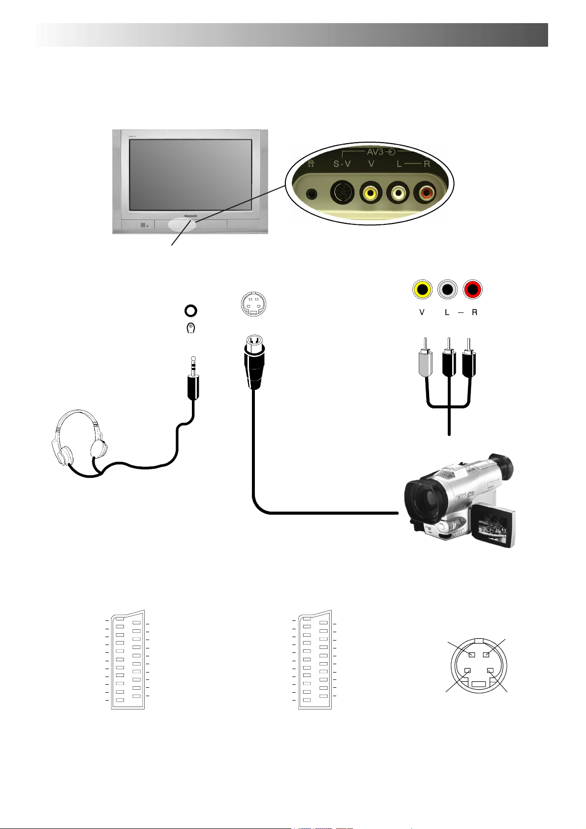
A
V
A
A
AUDIO / VIDEO CONNECTIONS
Front
Press and release to open
Output from
Headphone
socket
3RC
udio /Video and Headphone sockets
Video input to
S --- V
S --- V
S --- V i d e o s oc k e t
Video input to
V socket
Audio input to
L/R
sockets
3.5mm Stereo Plug
STEREO HEADPHONES
with 3.5mm Plug
Note :
Additional equipment and cables shown are not supplied with this TV set.
H Scart and S --- Video socket information
AV1 Scart socket
Socket Earth
CVBS out (video)
CVBS earth
Red in
Red earth
Green in
Green earth
Blue in
Blue earth
Audio out (L)
Audio out (R)
21
19
17
15
13
11
9
7
5
3
1
CVBS in (video)
20
RGB status earth
18
16
Status RGB
14
Earth
12
--- ---
10
--- ---
8
Status CVBS
6
Audio in (L)
4
Audio earth
Audio in (R)
2
AV2 Scart socket (S-- Video, Q-- Link)
Socket Earth
CVBS out (video)
CVBS earth
S.C. -- In
Earth
--- ---
Earth
--- ---
Earth
Audio out (L)
Audio out (R)
21
19
17
15
13
11
9
7
5
3
1
CVBS in (video)
20
18
16
--- ---
14
12
--- --Q --- Li nk d a t a
10
8
Status CVBS
6
Audio in (L)
4
Audio earth
Audio in (R)
2
Earth
Earth
RCA
Video
Cable
2xRCA
Cables
CAMCORDER
S --- V i d e o 4 p i n s o c k e t
Chrominance in
Chrominance ea rth
Audio
Luminance in
Luminance earth
Suitable inputs for AV1 include RGB
(Red/Green/Blue).
AV2 -- Pins 15 and 20 are dependent on
AV2 S-- VHS / VIDEO switching.
35
Page 36
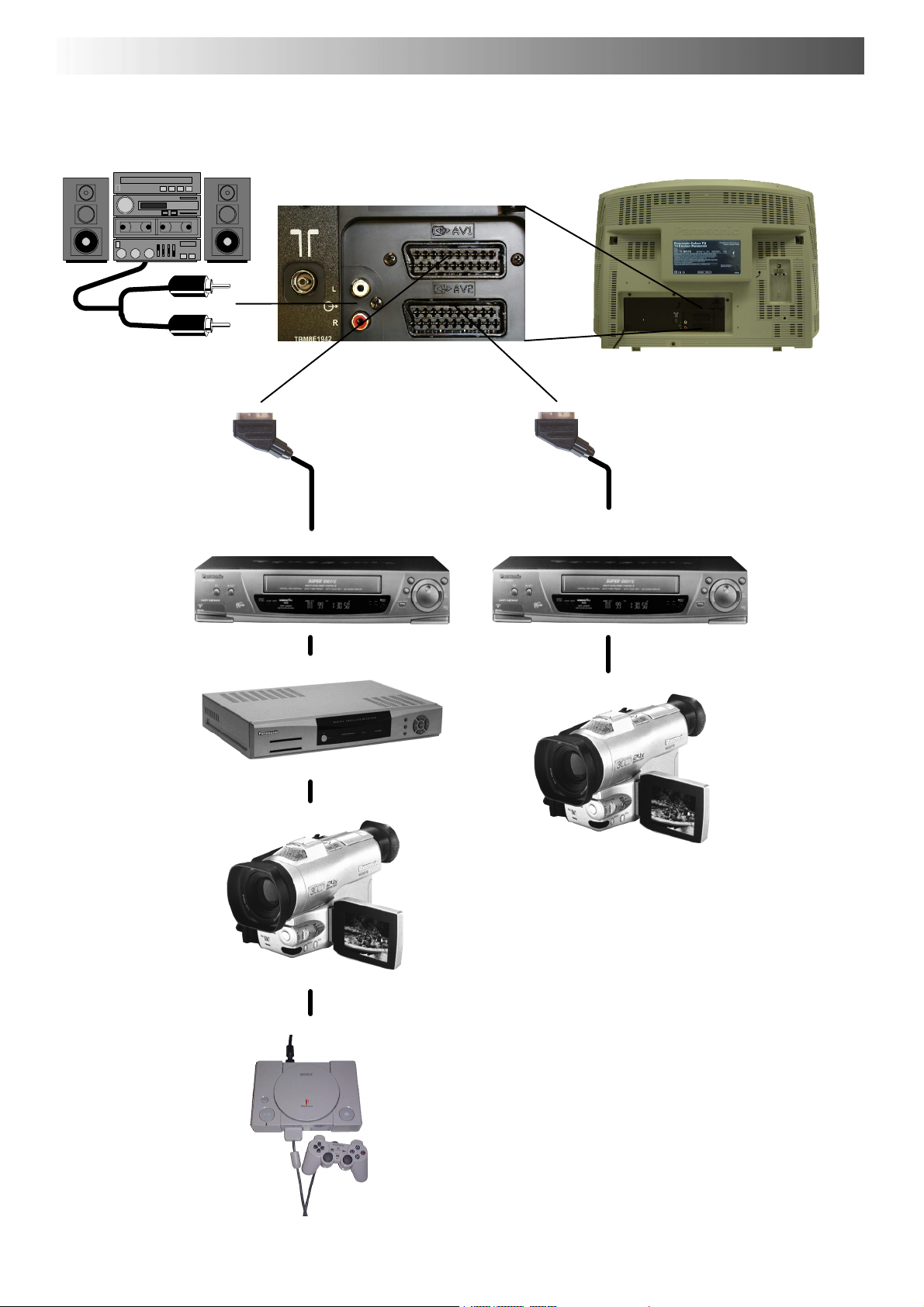
AUDIO / VIDEO CONNECTIONS
Rear AV1/AV2(S) 21 Pin Scart and RCA Audio Out terminals
HI--- FI SYSTEM
Output from
L --- R A U D I O O U T
Sockets
2xRCAAudio
Cables
Scart cable
Input/Output from
AV1 Scart Socket
VCR
SATELLITE RECEIVER
CAMCORDER
Scart cable
Input/Output from
AV2 Scart Socket
Q-- Link data
VCR
S-- VIDEO VCR
Q-- LINK COMPATIBLE VCR
S-- VIDEO CAMCORDER
36
GAMES CONSOLE / COMPUTER (RGB)
Notes:
Additional equipment and cables shown are not supplied with this TV set.
Do not connect a computer with TTL output (5V) to this set.
Page 37
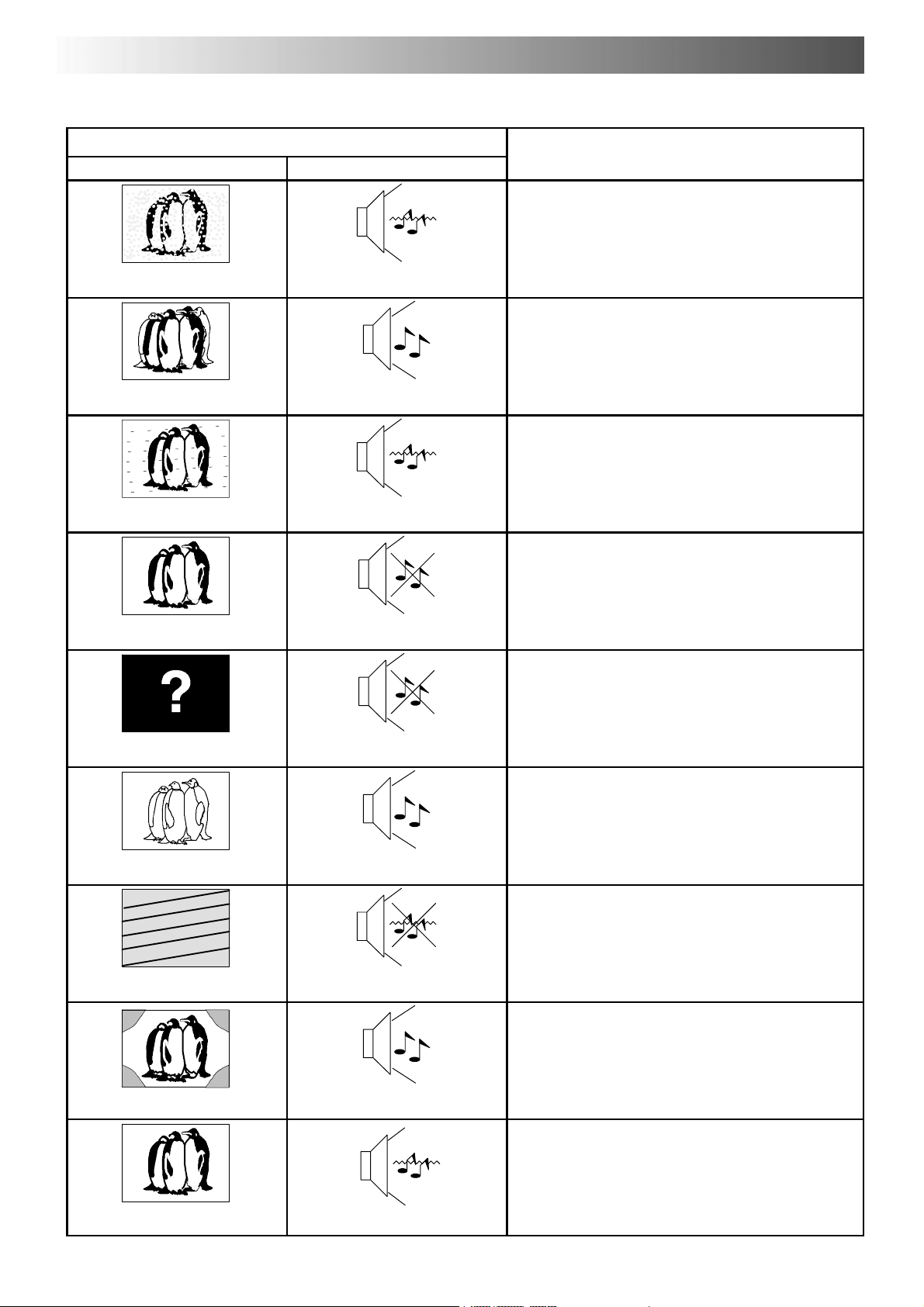
Check
s
TROUBLESHOOTING
Symptoms
Picture Sound
Aerial location, direction or connection
Snowy Picture
Multiple Images
Interference
Normal Picture
No Picture
Noisy Sound
Normal Sound
Noisy Sound
No Sound
No Sound
Aerial location, direction or connection
Electrical appliances
Cars / Motorcycles
Fluorescent lights
Switch on P --- NR in Picture menu to reduce picture
noise.
Volume level
Sound mute switched on
TV set to AV mode
Not plugged into A.C. outlet
Not switched on
Picture / Sound controls set at minimum levels
Check if in standby mode
No Colour
Poor or Distorted Picture
Coloured Patches
Normal Picture
Normal Sound
Weak or No Sound
Normal Sound
Weak or distorted sound
Colour controls set at minimum levels
Retune Channel(s)
Magnetic Interference from unshielded equipment
Receiver moved while switched ON, switch TV off for
30 minutes.
If picture is also tilted, use Geomagnetic Correction
feature (see Quick Start Guide, page 11)
Sound reception may have deteriorated.
Switch NICAM setting (Sound menu) to Off until
reception improves.
37
Page 38

A
A
L
(
VCR)
PAL525/60
PlaybackofNTSCtapefromsomePALVideorecorders(VCR
)
V
FORYOURGUIDANCE
H Service
Before requesting service, please refer to the troubleshooting
guide on previous page to determine the symptoms. To obtain
service please contact your local Panasonic dealer quoting the
model number and serial number (both are located at the rear of
the TV).
H TV Games / Home Computers
Extended use of TV games or home computers with any television
set can cause a permanent ‘shadow’ on the screen. This type of
irreversible picture tube damage, can be limited by observing the
following points:
D Reduce the brightness and contrast levels to a minimum
viewing level.
D Do not operate the television set for a continuous period of
time while using TV games or home computers.
D This type of picture tube damage, is not an operating
defect, and as such is not covered by the Panasonic
warranty.
SPECIFICATIONS
H Last Position Memory
Certain functions have a last position memory, i.e. the setting at
thetimeofswitch-- off will be the setting used when the receiver is
switched on again:-Programme Tint (M.NTSC / NTSC only)
Mode Volume correction (in AV mode only)
AV Position Contrast
Volume Sharpness
NICAM Aspect mode
Bass Standby
T reble Artificial Intelligence (AI)
Balance Colour
Colour Balance Brightness
Status P-- NR
Teletext mode Decoder (AV2)
Ambience Geomagnetic correction
H Sleep Feature
If the set is not switched off when the TV station stops
transmitting , it will automatically go to standby mode after 30
minutes. This function will not operate when the TV is in AV
mode.
TX-- 28PL1
Power Source 220 -- 240V 50Hz A.C.
Power Consumption 90W
Standby Consumption
Picture Tube
Visible Diagonal
Audio Output
Music Power
H
Dimensions
Weight (Kg) 42
Receiving
Systems/
Band name
Aerial -- Rear UHF
Headphones -- Front 3,5mm, 8Ω impedance
AV -- Rear
W
D
PAL I UHF E21-- 68
P
L 525/60 Playback ofNTSC tapefrom some P
M.NTSC Playback from M.NTSC Videorecorders (VCR)
NTSC (A
input only) Playbackfrom NTSCVideorecorders (VCR)
AV2 -- 21 pin terminal -- Audio / Video in/out, S-- Video in, Q-- Link
FrontLeft/Right15Wx2,8Ω impedance
AV1 -- 21 pin terminal -- Audio/Videoin/out,RGBin.
2 x RCA Audio Monitor Out
1.4W
66 cm
508,8 mm
763,2 mm
512,2 mm
Video recorders
AV -- Front AV3 -- S-- Video in, 2 x RCA Audio in, 1 x RCA Video in
Specifications are subject to change without notice. Weight and dimensions shown are approximate.
38
Page 39

NOTES
39
Page 40

Sales and Support Information
Customer Care
S For UK customers: 08705 357357.
S For Republic of Ireland customers: 01 289 8333.
S Visit our website for product information
www.panasonic.co.uk.
Direct Sales at Panasonic
S Order accessory and consumable items for your
product with ease and confidence by phoning
ourCustomerCareCentreMonday---Friday
9:00am--- 5:30pm (Excluding public holidays).
S Or go on line through our Internet Accessory
ordering application at www.panasonic.co.uk.
S Most major credit and debit cards accepted.
S All enquiries, transactions and distribution facilities
are provided directly by Panasonic UK Ltd.
S It couldn’t be simpler!
S Also available through our Internet is direct
shopping for a wide range of finished products,
take a browse on our website for further details.
Centre
UK
40
2003CS
Panasonic (U.K.) Ltd
Willoughby Road, Bracknell,
Berks RG12 8FP
 Loading...