

Panasonic tx 21gv1c schematic

Colour Television
Video Combination
Z-421V Chassis
SPECIFICATIONS FOR TV TECHNISCHE DATEN
(All figures in brackets { } refer to TX-14GV1C)
Power Source: 220-240V a.c., 50Hz
Power Consumption: 69W{54W}
Stand-by Power
Consumption: 3W
Aerial Impedance: 75Ω unbalanced, Coaxial Type
Receiving System: PAL B/G, H, PAL-525/60
SECAM B/G
M.NTSC
NTSC (AV only)
Receiving Channels:
VHF E2-E12 VHF H1-H2 (ITALY)
VHF A-H (ITALY) VHF R1-R2
VHF R3-R5 VHF R6-R12
UHF E21-E69 CATV (S01-S05)
CATV S1-S10 (M1-M10) CATV S11-S20 (U1-U10)
CATV S21-S41 (HYPERBAND)
Intermediate Frequency:
Video 38,9MHz
Audio 33,4MHz
Colour 34,47MHz
Video/Audio Terminals:
AV IN (Rear) Video (21 pin) 1V p-p 75Ω
Audio (21 pin) 500mV rms 10kΩ
RGB (21 pin)
AV OUT (Rear) Video (21 pin) 1V p-p 75Ω
Audio (21 pin) 500mV rms 1kΩ
AV Front Audio (RCAx1) 500mV rms 10kΩ
Video (RCAx1) 1V p-p 75Ω
High Voltage: 28kV ± 1,5kV
{25kV ± 1,5kV}
Picture Tube: A51EAL155X17 (51cm)
{A34EAC01X (34cm)}
Audio Output Mono: 2 x 1,5W 8Ω Impedance
(Music Power) {2W 16Ω Impedance}
Headphones: 300Ω Impedance
3,5mm
Accessories
supplied : Remote Control
2 x R6 (UM3) Batteries
Indoor Antenna {14" only}
Dimensions:
Height: 532mm {396,5mm}
Width: 514mm {386mm}
Depth: 485,2mm {367, 5m m }
Net weight: 24kg {13kg}
Specifications are subject to change without notice.
Weights and dimensions shown are approximate.
NOTE: This Servi ce Manual should be used in conjunction with the
Z-421V Technical guide.
(Werte in klammern gelten { } nur fur TX-14GV1C)
Netzpannung: 220-240V a.c., 50Hz
Leistungsaufnahme: 69W{54W}
Leistungsaufnahme: 3W
Antennenimpedanz: 75Ω asymmetrisch, Koaxial-Typ
Standby
Empfangssystem: PAL B/G, H, PAL-525/60
SECAM B/G
M.NTSC
NTSC (nur AV Eingang)
Empfangsbereiche:
VHF E2-E12 VHF H1-H2 (ITALY)
VHF A-H (ITALY) VHF R1-R2
VHF R3-R5 VHF R6-R12
UHF E21-E69 CATV (S01-S05)
CATV S1-S10 (M1-M10) CATV S11-S20 (U1-U10)
CATV S21-S41 (HYPERBAND)
Zwischenfrequenz:
Video 38,9MHz
Sound 33,4MHz
Colour 34,47MHz
Video/Audio Anschlüsse:
AV EINGANG (hinten) Video (21 pin) 1V p-p 75Ω
Audio (21 pin) 500mV rms 10kΩ
RGB (21 pin)
AV AUSGANG (hinten) Video (21 pin) 1V p-p 75Ω
Audio (21 pin) 500mV rms 1kΩ
AV (vorne) Audio (RCAx1) 500mV rms 10kΩ
Video (RCAx1) 1V p-p 75Ω
Hochspannung: 28kV ± 1,5kV
{25kV ± 1,5kV}
Bildrohre: A51EAL155X17 (51cm)
{A34EAC01X (34cm)}
Ton Ausgangsleistung:2 x 1,5W 8Ω Impedance
Mono {2W 16Ω Impedance}
Kopfhörer: 300Ω Impedanz
3,5mm
Mitgel. Zubehör: Fernbedienung
2 x R6 (UM3) Batterien
Nur TX-14GV1C zimmerantenne
Abmessungen:
Höhe: 532mm {396,5mm}
Breite: 514mm {386mm}
Tiefe: 485,2mm {367,5mm}
Gewicht: 24kg {13kg}
Änderungen der Technisich en Dat en vor be halt en .
Gewichte und Abmessungen sind Näherungsangaben.
Hinweis: Bitte verwende Sie das Service Manual zusammen mit
dem Technical Guide
ORDER No. SM-99062
TX-21GV1C
TX-14GV1C

SPECIFICATIONS FOR VCR
GENERAL
AUDIO
VIDEO
temperature 5°C ~ 35°C (operating)
-20°C ~ 60°C (storage temperature)
format standard
tape width 12,65mm
tape speed SP: 23,39mm/sec
LP: 11,70mm/sec
max. recording time with
full-size cassette
recording system longitudinal track
input
output
frequency range 100Hz to 8KHz
signal to noise ratio 40dB(more than)
signal system PAL/SECAM colour and CCIR mono chrome signals,
recording system Rotary 4-head helical scan with a slant double azimuth
input
output
signal to noise ratio 45dB with NETTETE IMAGE control at center position.
horizontal resolution 240 lines with NETTETE IMAGE control at center position
SP: 240min. with E-240 video cassette
LP: 480min. with E-240 video cassette
-3,8dBm(500mVrms), more than 47kΩ, unbalanced.
-3,8dBm(500mVrms),less than 1kΩ, unbalanced
625lines/50fields.
combination video head.
1Vp-p, 75Ω, unbalanced
1Vp-p, 75Ω, unbalanced
SPEZIFIKATIONEN FÜR DEN VCR (VIDEORECORDER)
ALLGEMEIN
AUDIO
VIDEO
Temperatur 5ºC - 35ºC (Betriebstemperatur)
-20ºC - 60ºC (Lagertemperatur)
Format Standard
Bandbreite 12,65mm
Bandgeschwindigkeit SP: 23,39mm/Sek
LP: 11,70mm/Sek
Max. Aufnahmezeit mit
Kassette normaler
Größe
Aufnahmesystem Längsspurverfahren
Eingabe -3,8dBm(500mVrms), mehr als 47 1 kΩ, unsymmetrisch
Ausgabe
Frequenzbereich 100Hz bis 8khz
Rauschverhältnis 40dB (mehr als)
Signalsystem PAL/SECAM-Farb- und CCIR-Schwarzweiß-Signale
Aufnahmesystem 4-Kopf-Rotationsschrägspuraufzeichnung mit schrägem DoppelazimuthEingabe 1Vp-p,75Ω, unsymmetrisch
Ausgabe
Rauschverhältnis 45dB mit NETTETE-Bildkontrolle auf mittlerer Position
Horizontale Auflösung 240 Zeilen mit NETTETE-Bildkontrolle auf mittlerer Position
SP: 240Min. mit E-240 Video-Kassette
LP: 480Min. mit E-240 Video-Kassette
-3,8dBm(500mVrms), weniger als 1 k
625 Zeilen / 50 Felder
Kombinations-Videokopf.
1Vp-p,75
, unsymmetrisch
Ω
, unsymmetrisch
Ω
2

CONTENTS INHALT
SPECIFICATIONS FOR VCR 2
SAFETY PRECAUTIONS 3
SERVICE HINTS & DISASSEMBLY 5
ADJUSTMENT PROCEDURE 8
ALIGNMENT SETTINGS 10
DESCRIPTION OF THE VCR MECHANISM 12
BLOCK DIAGRAMS 42
PARTS LOCATION (TV) 45
REPLACEMENT PARTS LIST (TV) 46
PARTS LOCATION (VCR) 55
REPLACEMENT PARTS LIST (VCR) 56
SAFETY PRECAUTIONS
GENERAL GUIDE LINES
1. It is advisable to insert an isolation transformer in the
a.c. supply before servicing a hot chassis.
2. When servicing, observe the original lead dress in the
high voltage circuits. If a short circuit is found, replace
all parts which have been overheated or damaged by
the short circuit.
3. After servicing, see that all the protective devices such
as insulation barriers, insulation papers, shields and
isolation R-C combinations are correctly installed.
4. When the receiver is not being used for a long period
of time, unplug the power cord from the a.c. outlet.
5. Potentials as high as 29,5kV { 26,5kV } are present
when this receiver is in operation. Operation of the
receiver without the rear cover involves the danger of a
shock hazard from the receiver power supply.
Servicing should not be attempted by anyone who is
not familiar with the precautions necessary when
working on high voltage equipment. Always discharge
the anode of the tube.
6. After servicing make the following leakage current
checks to prevent the customer from being exposed to
shock hazard.
LEAKAGE CURRENT COLD CHECK
1. Unplug the a.c. cord and connect a jumper between
the two prongs of the plug.
2. Turn on the receiver’s power switch.
3. Measure the resistance value with an ohmmeter,
between the jumpered a.c. plug and each exposed
metallic cabinet part on the receiver, such as screw
heads, aerials, connectors, control shafts etc. When
the exposed metallic part has a return path to the
chassis the reading should be between 4M ohm and
20M ohm. When the exposed metal does not have a
return path to the chassis the reading must be infinite.
SPEZIFIKATIONEN FÜR DEN VCR 2
SPEZIFIKATIONEN FÜR DEN VCR 3
WARTUNGSTIPS, DEMONATGE 5
EINSTELLUERFAHREN 9
ABGLEICHEINSTELLUNGEN 11
BESCHREIBUNG DES VCR-MECHANISMUS 12
SCHALTBILD BLOCK 42
EXPLOSIONSZEICHNUNG (TV) 45
ERSATZTEILLISTE (TV) 46
EXPLOSIONSZEICHNUNG (VCR) 55
ERSATZTEILLISTE (VCR) 56
SICHERHEITSVORKEHRUNGEN
ALLGEMEINE RICHTLINIEN
1. Es ist empfehlenswert einen Trenntransformator in die
Stromversorgung zu schalten, bevor Reparaturen an
einem Gerät vorgenommen werden, dessen Chassis
unter Spannung steht.
2. Bei der Durchführung von Servicearbeiten dürfen die
ursprünglichen Kabelanschlüsse nicht vertauscht
werden. Dies gilt insbesondere für die Anschlüsse im
Hochspannungsteil. Hat sich ein Kurzschluß ereignet,
dann sind alle Teile, an denen Spuren von Überhitzung
sichtbar sind, auszuwechseln.
3. Nach Beenden der Servicearbeiten ist sicherzustellen,
daß alle Sicherheitsvorrichtungen, wie Isolationsstege,
Isolationspapiere, Abschirmungen und Isolations -R-CGlieder wieder richtig eingesetzt sind.
4. Wenn der Fernseher während längerer Zeit nicht in
Betrieb gesetzt wird, sollte der Netzstecker aus der
Netzsteckdose gezogen werden.
5. Im Betrieb sind Spannungen bis zu 29,5kV { 26,5kV }
in diesem Gerät vorhanden. Die Inbetriebnahme des
Fernsehers ohne aufgesetzte Rückwand bringt die
Gefahr eines elektrischen Schlages von der Fernseher
- Stromversorgung mit sich. Servicearbeiten solten
daher auch nie durch Personen versucht werden, die
nicht in vollem. Umfang mit den
Sicherheitsvorkehrungen beim Umgang mit
Hochspannungsgeräten vertraut sind. Vor der
Handhabung mit der Bildröhre ist die Anode der
Bildrohre immer an dem Empfängerchassis zu
entladen.
6. Nach Beenden der Servicearbeiten sind die folgenden
Kriechstrom-Prüfungen durchzuführen, um den
Kunden vor der Gefahr eines elektrischen Schlages zu
schützen.
MESSUNG DES ISOLATIONSWIDERSTANDES
IM ABGESCHALTETEN ZUSTAND
1. Den Netsztecker aus der Netzsteckdose ziehen und
die beiden Steckerstifte kurzschließen.
2. Den Geräteschalter des Fernsehgerätes einschalten.
3. Mit einem Ohmmeter den Widerstandswert zwischen
dem überbrückten Netzkabelste ckerund jendem
zugänglichen Metallteil am Gehäuse des
Fernsehgerätes, wie Schraubenköpfe, Antennen,
Achsen der Regler, Griffassungen usw.messen. Wenn
ein zugängliches Metallteil keine Rückleitung zum
Chassis hat, Muß die Anzeige unendlich betrgen.
3
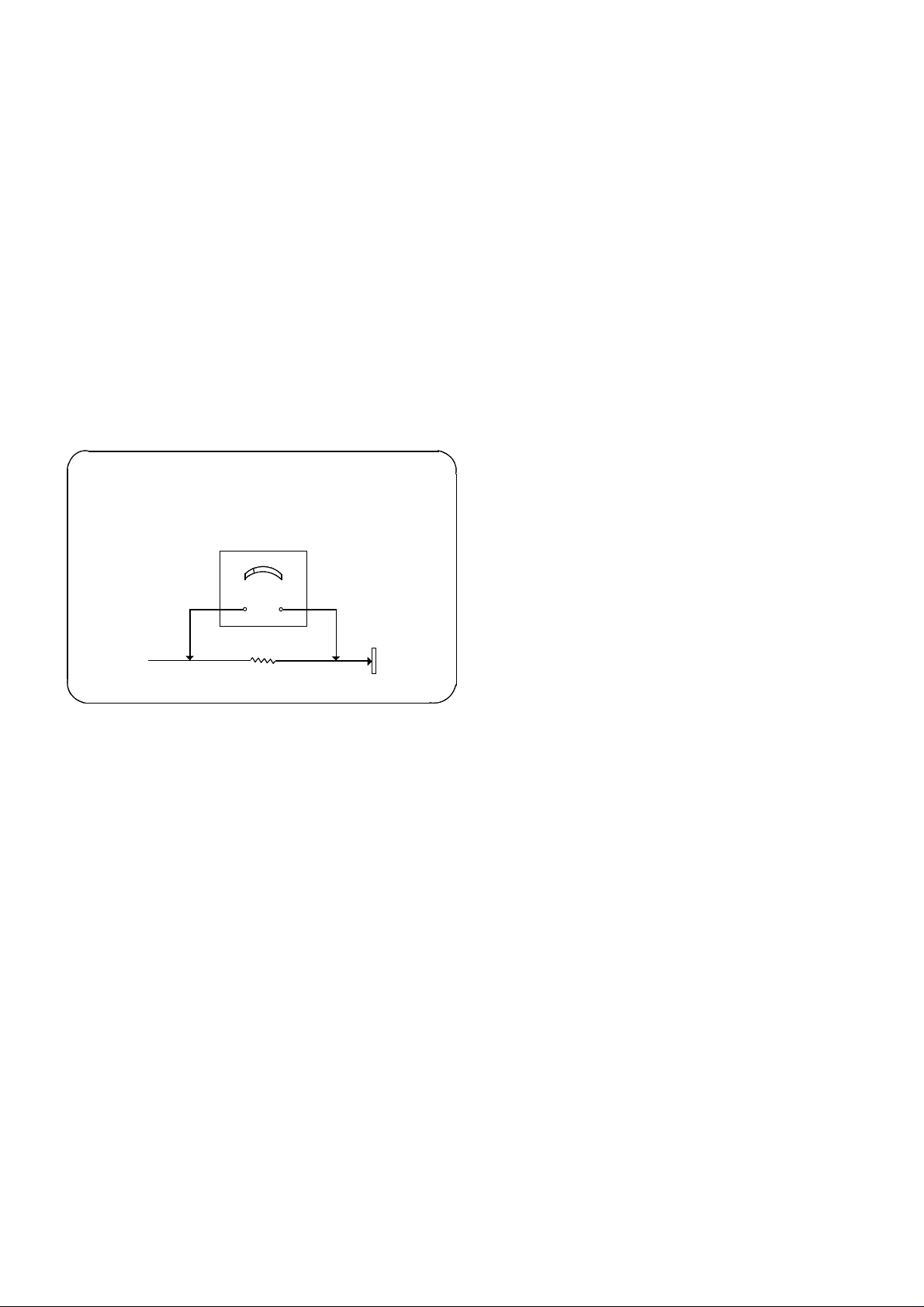
LEAKAGE CURRENT HOT CHECK
1. Plug the a.c. cord directly into the a.c. outlet. Do not
use an isolation transformer for this check.
2. Connect a 2kΩ 10W resistor in series with an exposed
metallic part on the receiver and an earth, such as a
water pipe.
3. Use an a.c. voltmeter with high impedance to measure
the potential across the resistor.
4. Check each exposed metallic part and check the
voltage at each point.
5. Reverse the a.c. plug at the outlet and repeat each of
the above measurements.
6. The potential at any point should not exceed 1,4 V rms.
In case a measurement is outside the limits specified,
there is a possibility of a shock hazard, and the
receiver should be repaired and rechecked before it is
returned to the customer.
HOT CHECK CIRCUIT
SCHALTUNGSAUFBAU FÜR PRUFUNG
IM EINGESCHALTETEN ZUSTAND
a.c.. VOLTMETER
WECHSELSTROM-VOLTMETER
MESSUNG DES KRIECHSTROMS IM
EINGESCHALTETEN ZUSTAND
1. Den Netzstecker direkt in eine Netsteckdose stecken.
Für diese Messung keinen Trenntransformator
verwenden.
2. Einen 2kΩ / 10W-Widerstand in Serie mit einem von
außen zugänglichen Metallteil am Fernsehgerät und
einer guten, Erdung z.B Wasserleitung, anschließen.
3. Ein Wechselstrom-Voltmeter mit einem Meßbereich
von 1000 Ohm.Volt oder größer verwenden, um die
Spannung über den Widerstand zu messen.
4. Jedes zugängliche Metallteil prüfen, und an jedem
Punkt dies Spannung messen.
5. Den Netztecker umgekehrt in die Steckdose stecken
und jede der obigen Messungen wiederholen.
6. Die Spannung darf an keinem der Punkte 1,4V eff.
überschreiten. Wird dieser Wert nicht eingehalten,
besteht die Gefar eines elektrischen Schlages, und das
Fernsehgerät sollte daher repariert und nachge prüft
werden, bevor es an den Kunden zurückgegeben wird.
TO INSTRUMENT’S
EXPOSED
METALLIC PARTS
AN ZUGANGLICHE
METALLTEILE DAS
TV-GERATES
2k ohm
Water Pipe
(Earth)
Wasserleitun g
(Erdung)
Fig.1.
Abb.1.
X-RADIATION WARNING
1. The potential sources of X-Radiation in TV sets are the
high voltage section and the picture tube.
2. When using a picture tube test jig for service, ensure
that the jig is capable of handling 29,5kV { 26,5kV }
without causing X-Radiation.
NOTE : It is important to use an accurate
periodically calibrated high voltage meter.
1. Set the brightness to minimum.
2. Measure the high voltage. The meter should indicate
28kV 1,5kV { 25kV ± 1,5kV }. If the meter indication
is out of tolerance, immediate service and correction is
required to prevent the possibility of premature
component failure.
3. To prevent any X-Radiation possibility, it is essential to
use the specified tube.
RÖNTGENSTRAHLUNG ACHTUNG :
1. Potentielle Quellen von Röntgenstrahlung in
Fernsehgeräten sind das Hochspannungsteil und die
Bildröhre.
2. Bei Verwendung eines Bildröhren-Prüfgerätes für den
Service ist sicherzustellen, daß es für die Belastung
von 29,5kV { 26,5kV } geeignet ist, ohne daß eine
Röntgenstrahlung verursacht wird.
ANMERKUNG : Es ist wichtig, daß ein präzises,
regelmäßig geprüftes Voltmeter verwendet wird.
1. Helligkeit auf Minimum stellen.
2. Die Hochspannung messen. Die Anzeige des
Instrumentes sollte 28kV ± 1,5kV { 25kV ± 1,5kV }.
Falls die Anziege diese Toleranzgrenzen überschreitet,
ist die sofortige Behebung nötig, um die Möglichkeit
vorzeitigen Komponentenausfalls zu verhüten.
3. Um die Möglichkeit von Röntgenstrahlung zu
begrenzen, ist es wichtig, daß nur die vorgeschriebene
Bildröhre verwendet wird.
4
SERVICE HINTS WARTUNGSTIPS
p
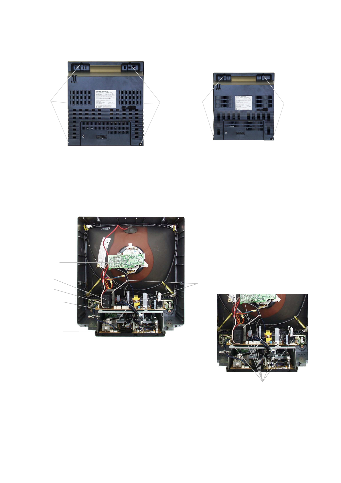
How to remove the rear cover
1) Remove the screws as shown in Fig.2/Fig.3.
TX-21GV1C
Screws
Schraube
Fig.2.
Abb.2.
Entfernung der hinteren Abdeckung
1) Die Schrauben wie in Abb.2/ Abb.3 dargestellt
entfernen.
Screws
Schraube
DISASSEMBLY DEMONATGE
1) Remove the 2 cable ties shown in Fig.4.
2) Remove the 7 connectors shown in Fig.5.
1) Die beiden Kabelhalter wie in Abb.4 dargestellt
entfernen.
2) Die 7 Anschlußstecker, die in Abb.5 dargestellt sind,
entfernen.
TX-14GV1C
Screws
Schraube
Fig.3.
Abb.3.
CRT Board
KSR-Platine
Focus
Brenn
unkt
Screen
Bildschirm
Power Board
Netzplatine
Main Board
Hauptplatine
Cable Ties
Fig.2.
Fig.4.
Abb.4.
Connectors
Anschlußstecker
Fig.5.
Abb.5.
5

DISASSEMBLY (Cont.) DEMONATGE (FORTSTZG.)
Earth strap
Connectors
Screws
3) Remove earth strap shown in Fig.7.
4) Remove the 6 screws, three each side, from the top
cover, as shown in Fig.6.
5) Remove the speaker connector as shown in Fig.6.
6) Lift top cover and remove main pcb.
Speaker Connector
Anschlußstecker für
Lautsprecher
Screws
Schrauben
Fig.6.
Abb.6.
Top Cover
Abdeckung
3) Den in Abb.7 dargestellten Erdungsgurt entfernen.
4) Die 6 Schrauben, drei an jeder Seite, von der oberen
Abdeckung entfernen wie in Abb.6 dargestellt.
5) Den Anschlußstecker für den Lautsprecher wie in
Abb.6 dargestellt herausziehen.
6) Obere Abdeckung abheben und Hauptplatine
entfernen.
Erdunggurt
Obere
Fig.7.
Abb.7.
7) Remove the 5 screws as shown in Fig.8.
8) Remove the head connector seal cover shown in
Fig.8.
9) Remove the 4 connectors shown in Fig.9.
Head Connector Seal Cover
Abdichtungsdeckel des
Kopfhöreranschlusses
Fig.8.
Abb.8.
7) Die 5 Schrauben wie in Abb. 8 dargestellt entfernen.
8) Den Abdichtungsdeckel des Kopfhöreranschlusses wie
in Abb. 8 dargestellt entfernen.
9) Die 4 in Abb. 9 dargestellten Anschlußstecker
herausziehen.
Schrauben
Connectors
Anschlußstecker
Fig.9.
Abb.9.
Anschlußstecker
6

DISASSEMBLY (Cont.) DEMONATGE (FORTSTZG.)
10) Remove the 5 screws shown in Fig.10.
11) Release the 5 chassis frame clips (shown in Fig.11.)
and remove the main P.C.B. from the chassis frame.
10) Die 5 in Abb.10 dargestellten Schrauben entfernen.
11) Die 5 (in Abb.11 dargestellten) Rahmenklamme rn
lösen und die Hauptplatine aus dem Rahmen
nehmen.
Screws
Schrauben
Clips
Klammern
Screws
Schrauben
Fig.10.
Abb.10.
Clips
Klammern
Fig.11.
Abb.11.
7

ADJUSTMENT PROCEDURE
Item / Preparation Adjustments
Sub Tuner AFT
1) Set a signal generator with
-RF FREQUENCY = 38,9MHz
-RF OUTPUT LEVEL = 80±5dBuV.
2) Connect a signal generator RF output to TP2 (TUNER IF
OUTPUT). Ensure there is no signal input to the
TUNER.
3) Connect the DC voltage meter to TP3.
Adjust L201 (AFT COIL) for 2,2V ± 0,1V.
Main Tuner AGC
1) Set a pattern generator with RF level 60 ± 2dBuV,
210,25MHz.
2) Connect an oscilloscope to P101 (Tuner AGC Input).
Sub Tuner AGC
1) Set a pattern generator with RF level 60 ± 2dBuV,
210,25MHz.
2) Connect an oscilloscope to P101 (Tuner AGC Input).
Screen
1) Apply a Colour Bar Pattern signal.
2) Connect an oscilloscope to P906 (CRT Cathode RGB).
3) Press the SCREEN key.
Focus
1) Apply a RETMA Pattern signal.
White Balance
1) Apply a Colour Bar Pattern signal.
X-Position Adjustment, P2 and P3
1) Play DP-2 Test tape (Colour bar, Audio 6KHz).
2) Enter Service Mode using Service Remote and
deactivate Auto-Tracking by pressing ATK-OFF key.
3) Set oscilloscope to CHOP mode and connect CH1 to
VIDEO HEAD SW (PYO4 pin 6). Connect CH2 to the
PB ENVE (PYO4 pin 4) and trigger CH1.
Adjust using "AGC UP/DOWN" key until the voltage drops to
1,0Vdc ±0,2Vdc below its maximum voltage.
Press the "SUB AGC" key in Service mode and monitor the
SUB TUNER picture whilst adjusting R202 (SUB AGC VR) to
1,0Vdc ±0,2Vdc below its maximum voltage.
Adjust the screen volume on the FBT so that the highest
black level voltage is 130V ± 5Vdc {150V ± 5Vdc}.
Adjust FOCUS VOLUME on the FBT for optimum setting.
Adjust the RGB UP/DOWN key to obtain optimum
WHITE BALANCE.
Adjust, with the corn screw, until both TRK MAX and
TRK MIN have the same size of envelope.
Adjust P2, P3 so that both the beginning and the end of the
envelope waveform are flat.
Azimuth Adjustment
1) Connect an oscilloscope to the AUDIO OUTPUT
terminal (P601).
After test tape playback, adjust the output level, using the
outer screw of the A/C head to obtain maximum waveform.
(6KHz -3,8dBm +1dBm / -3dBm).
Fix the azimuth screw with locking paint.
8

EINSTELLVERFAHREN
Posten / Vorbereitung Einstellungen
Sub-Tuner AFT
1) Stellen Sie einen Signalgenerator ein mit
-HF-Frequenz = 38,9Mhz
-HF-AUSGANGSPEGEL = 80±5dBuV.
2) Schließen Sie einen Signalgenerator mit HF-Ausgang
an TP2 an (TUNER WENN AUSGANG). Stellen Sie
sicher, daß keine Signaleingabe in den Tuner erfolgt.
3) Schließen Sie den Gleichspannungsmesser an TP3 an.
Stellen Sie L201 (AFT-Spule) für 2,2V ± 0,1V ein.
Haupttuner-AGC
1) Stellen Sie einen Mustergenerator ein mit HF-Pegel 60 ±
2 dBuV, 210,25mhz
2) Schließen Sie ein Oszilloskop an P101 (Tuner-AGC-
Eingang).
Sub-Tuner-AGC
1) Stellen Sie einen Mustergenerator ein mit HF-Pegel 60 ±
2 dBuV, 210,25mhz
2) Schließen Sie ein Oszilloskop an P101 (Tuner-AGC-
Eingang).
Bildschirm
1) Steuern Sie ein Farbbalken-Mustersignal an.
2) Schließen Sie ein Oszilloskop an P906 (KSR-Kathoden-
RGB).
3) Drücken Sie die SCREEN-Taste.
Brennpunkt
1) Steuern Sie ein RETMA-Mustersignal an
Weißabgleich
1) Steuern Sie ein Farbbalken-Mustersignal an.
X-Positionseinstellung, P2 und P3
1) Spielen Sie das DP-2 Testband ab (Farbbalken,
Tonfrequenz 6khz).
2) Gehen Sie mittels Fernbedienung in Wartungsmodus
und deaktivieren Sie automatische Zielverfolgung, indem
Sie die ATK-OFF-Taste drücken.
3) Stellen Sie das Oszilloskop auf CHOP-Modus und
schließen Sie CH1 an den VIDEO HEAD SW
(PY04 Stift 6) an. Schließen Sie CH2 an den PB ENVE
(PY04 Stift 4) an und triggern Sie CH1.
Machen Sie die Einstellung unter Verwendung der “AGC
UP/DOWN-Taste, bis die Spannung auf 1,0Vdc ±0,2Vdc GS
unter die Höchstspannung fällt.
Drücken Sie im Wartungsmodus die “SUB-AGC”-Taste und
überwachen Sie das SUB-TUNER-Bild, während Sie R202
(SUB-AGC-VR) auf 1,0V GS unter seine Höchstspannung
einstellen.
Stellen Sie das Bildschirm-Volumen auf dem FBT so ein,
daß die Höchstspannung des Schwarzwertes 130V ± 5V GS
{150V ± 5V GS} beträgt.
Stellen Sie das Brennpunkt-Volumen auf dem FTB auf
optimale Einstellung.
Machen Sie die Einstellung mittels der RGB UP/DOWNTaste, um einen optimalen WEISSABGLEICH zu erzielen.
Machen Sie die Einstellung mittels der Com-Schraube, bis
TRK MAX und TRK MIN beide die gleiche Hüllkurvengröße
haben.
Stellen Sie P2, P3 so ein, daß sowohl der Anfang als auch
das Ende der Hüllkurvenform flach sind.
Azimutheinstellung
1) Schließen Sie ein Oszilloskop an den AUDIO OUTPUT-
Anschluß an.
Nach Rückspielen des Testbandes den Ausgabepegel
mittels der äußeren Schraube des WS-Kopfes auf maximale
Kurvenform einstellen. (6kHz - 3,8dBm + 1 dBm / -3dBm.
Stellen Sie die Azimuth-Schraube mit Sperrlack fest.
9

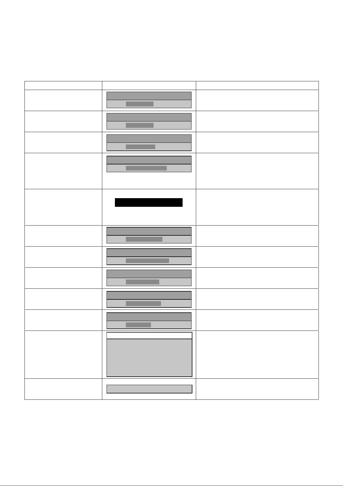
ALIGNMENT SETTINGS:
(The figures below are nominal and used for representative purposes only.)
1) Place the TV in Programme position 70, set the Sharpness to minimum position, press the down button (- / v) on the
customer controls at the front of the TV and at the same time press the VCR INDEX button on the remote control, this
will place the TV into the Service Mode.
2) Press the RED / GREEN buttons to step up / down through the functions.
3) Press the YELLOW / BLUE buttons to alter the function values.
4) To exit the Service Mode, press the "EXIT" button.
Alignment Function Settings / Special features
Blue correction Optimum setting (for white balance).
Green correction Optimum setting (for white balance).
Red correction Optimum setting (for white balance).
AGC
Sub AGC
Horizontal Centre Optimum setting.
Vertical Size Optimum setting.
B
23
G
23
R
24
AGC
41
H-CENTER
32
V-SIZE
51
SUB AGC 1
Set Pattern generator with RF level 60+/- 2dBuV,
210,25MHz. Connect oscilloscope to P101
(Tuner AGC input). Adjust AGC using
Yellow /Blue buttons until the voltage drops to
1.8V dc below its maximum voltage.
Press this button to access SUB TUNER AGC
adjustment.
Press once: picture is displayed in colour.
Press twice: picture is displayed in black and
white.
Vertical Centre Optimum setting.
Vertical Slope Optimum setting.
S-Correction Optimum setting.
OSD Language Adjust to change order of language selection
OSD Position Set Optimum setting.
V-CENTER
30
V.SLOPE
32
S-CORR
20
OSD language
English
Français
Italiano
Español
Nederlands
Deutsch
OSD POSITION SET
10
ABGLEICHEINSTELLUNGEN
(Die unten angegebenen Zahlen sind Nennwerte und dienen nur repräsentativen Zwecken.)
1) Stellen Sie den Fernseher auf Programm-Position 70 ein, stellen Sie die Schärfe auf Mindestposition, und drücken Sie
gleichzeitig die Nach-unten-Taste (- / v) an den Kunden-Kontrollvorrichtungen an der Vorderseite des Fernsehers und die
VCR-INDEX-Taste auf der Fernbedienung. Hierdurch wird der Fernseher auf Wartungs-Modus eingestellt.
2) Drücken Sie die ROT / GRÜN-Tasten, um nach oben / unten durch die Funktionen zu schreiten.
3) Drücken Sie die GELB / BLAU-Tasten, um die Funktionswerte zu ändern.
4) Um den Wartungs-Modus zu verlassen, drücken Sie die EXIT-Taste.
Abgleichfunktion Einstellungen / Besondere Merkmale
Blaukorrektur Optimale Einstellung (für Weißabgleich).
Grünkorrektur Optimale Einstellung (für Weißabgleich).
Rotkorrektur Optimale Einstellung (für Weißabgleich).
AGC
Sub-AGC
Horizontale Mitte Optimale Einstellung.
Vertikale Größe Optimale Einstellung.
B
23
G
23
R
24
AGC
41
H-CENTER
32
V-SIZE
51
SUB AGC 1
Stellen Sie einen Mustergenerator ein mit HFPegel 60 ± 2 dBuV, 210,25MHz. Schließen Sie
ein Oszilloskop an P101 (Tuner-AGC-Eingang).
Machen Sie die Einstellung unter Verwendung
der GELB / BLAU-Tasten, bis die Spannung auf
1,8V GS unter die Höchstspannung fällt.
Drücken Sie diese Taste, um Zugriff auf die
Einstellung SUB-TUNER-AGC zu nehmen.
Einmaliges Drücken: Das Bild wird in Farbe
angezeigt.
Zweimalige Drücken: Das Bild wird in SchwarzWeiß angezeigt.
Vertikale Mitte Optimale Einstellung.
Vertikale Neigung Optimale Einstellung.
V-Korrektur Optimale Einstellung.
OSD-Sprache
OSD-Position eingestellt Optimale Einstellung.
V-CENTER
30
V.SLOPE
32
S-CORR
20
OSD language
English
Français
Italiano
Español
Nederlands
Deutsch
OSD POSITION SET
Wählen Sie, in welcher Reihenfolge die
Sprachen aufgeführt werden sollen.
11
DESCRIPTION OF THE VCR MECHANISM
Characteristic of the K-Deck mechanism
_ K-Mecha Deck follows the VHS standard and uses three motors (DRUM MOTOR, CAPSTAN MOTOR and L/C MOTOR).
The L/C MOTOR is used to drive FRONT LOADING.
_ The deck recognises each mode by using a 4-BIT MODE signal. This 4-BIT MODE signal is generated by the CAM
SWITCH, which is driven by the L/C MOTOR.
_ There are 7 MODES which are utilised (EJECT / INITIAL / REV / IDLE / PLAY, STOP, SLOW / BRAKE / FF & REW).
_ The reduction of the mode shifting time, i.e. picture playing time, is enabled by using the FULL LOADING SYSTEM that has
the DRUM wrapped by the tape.
_ The Main PCB is separated from the Deck. When assembling, it is connected by the B-B TYPE CONNECTOR.
_ The CAPSTAN MOTOR and DRUM MOTOR are directly connected to the MAIN PCB DECK
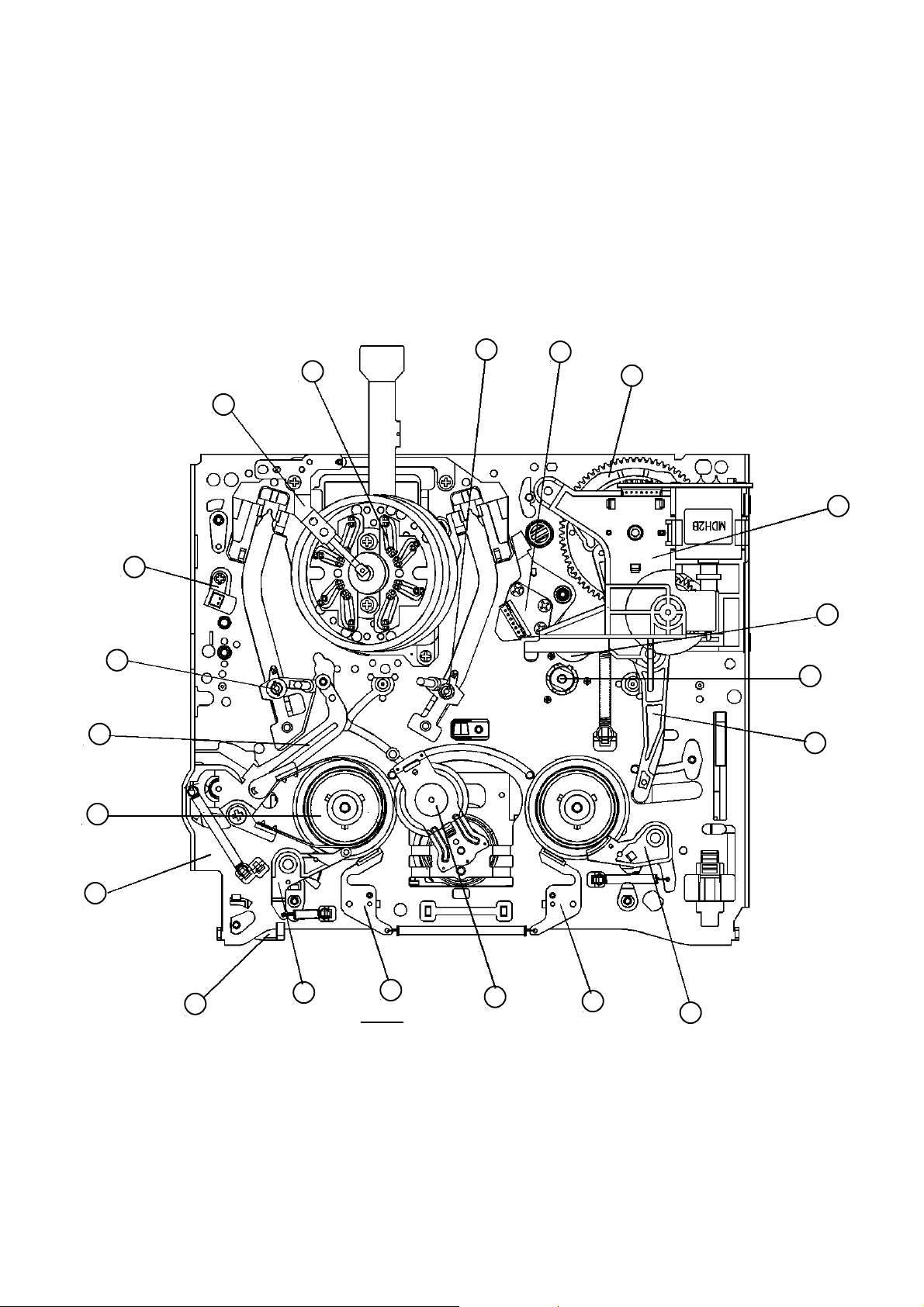
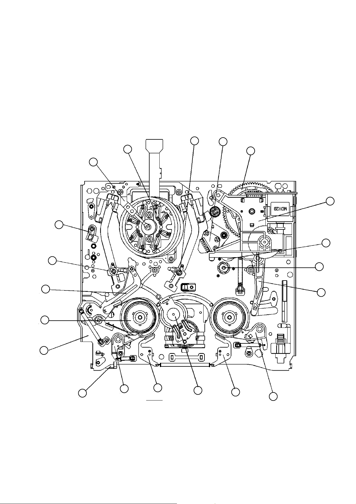
ASSEMBLY DIAGRAM OF DECK ASSEMBLY
TOP VIEW
18 17
19
1
16
15
2
14
3
13
4
5
6
20
7
8
Fig.12.
9
10
11
12
1) EARTH BRACKET ASSEMBLY 9) IDLER PLATE TOTAL ASSEMBLY 17) A/C HEAD TOTAL ASSEMBLY
2) FE HEAD 10) T MAIN BRAKE ASSEMBLY 18) T SLANT POLE ASSEMBLY
3) S SLANT POLE ASSEMBLY 11) T-BRAKE ASSEMBLY 19) DRUM TOTAL ASSEMBLY
4) TENSION BAND ASSEMBLY 12) RELAY LEVER 20) RECORD SAFETY LEVER
5) REEL TABLE 13) CAPSTAN MOTOR
6) MAIN BASE ASSEMBLY 14) PINCH LEVER TOTAL ASSEMBLY
7) S SUB BRAKE ASSEMBLY 15) L/C BRACKET TOTAL ASSEMBLY
8) S MAIN BRAKE ASSEMBLY 16) CAM GEAR
12
BESCHREIBUNG DES VCR-MECHANISMUS
Eigenschaften des K-Deck-Mechanismus
_ Das K-Mecha Deck entspricht dem VHS-Standard und verwendet drei Motoren (WALZENMOTOR,
BANDANTRIEBSMOTOR und H/N-MOTOR). Der H/N -Motor (Logic Control Motor) wird zum Antrieb des Frontladens
benutzt.
_ Das Deck erkennt jeden Modus anhand eines 4-BIT-MODUS-Signals, das durch den vom H/N -Motor angetriebenen
Nockenschalter erzeugt wird.
_ Es gibt 7 MODI, die angewendet werden können (EJECT / INITIAL / REV / IDLE / PLAY, STOP,
SLOW / BRAKE / FF & REW).
_ Die Reduzierung der Moduswechselzeit, wie z.B. Bildspielzeit, wird durch Verwendung des FULL LOADING SYSTEM
aktiviert, bei welchem die Walze vom Band umwickelt wird.
_ Die Hauptplatine ist vom Deck getrennt. Bei der Montage wird sie durch einen B-B-Typ Stecker angeschlossen.
_ BANDANTRIEBSMOTOR und WALZENMOTOR sind direkt an die Hauptplatine angeschlossen.
MONTAGE-SCHAUBILD DER DECKMONTAGE
Ansicht von oben
18 17
19
1
16
15
2
14
3
13
4
5
6
20
7
8
Abb.13.
9
10
11
12
1) Erdklemmen-Bausatz 9) Spannrollenplatte-Gesamtbausatz 17) WS-Kopf-Gesamtbausatz
2) FE-Kopf 10) A- Hauptbrems-Bausatz 18) A- Schrägpol-Bausatz
3) V-Schrägpol-Bausatz 11) A-Brems-Bausatz 19) Walzen-Gesamtbausatz
4) Spannungsband-Bausatz 12) Relais-Hebel 20) Aufnahme-Sicherheitshebel
5) Spulentisch 13) Bandantriebsmotor
6) Hauptgrundplatten-Bausatz 14) Abschnürhebel-Gesamtbausatz
7) V-Subbrems-Bausatz 15) H/N -Klammer-Gesamtbausatz
8) V-Hauptbrems-Bausatz 16) Nockensteuerung
13
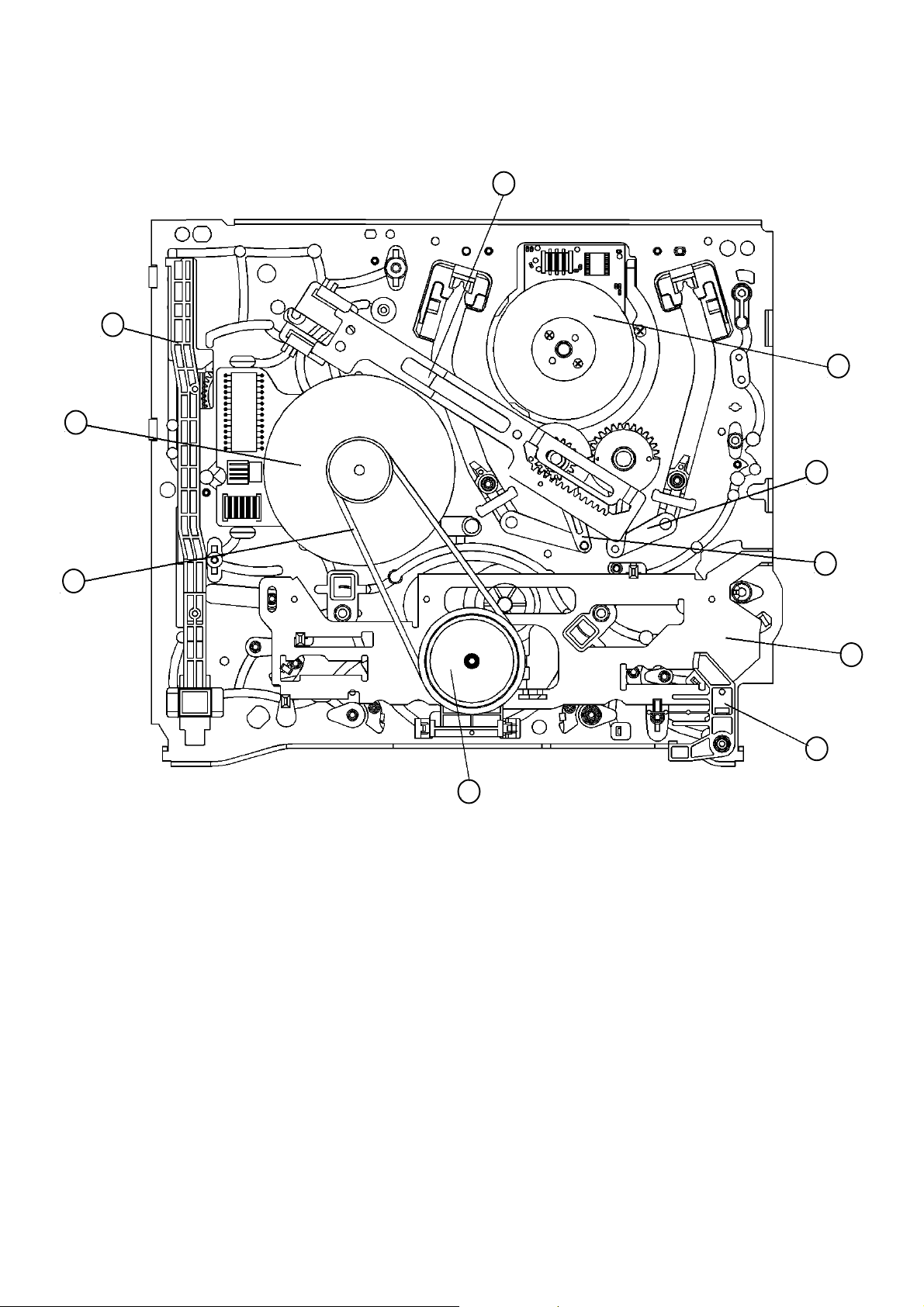
ASSEMBLY DIAGRAM AND MAJOR PARTS CHECK
BOTTOM VIEW
10
2
1
9
7
8
4
3
6
5
Fig.14.
1) CAPSTAN MOTOR 5) REEL GEAR TOTAL ASSEMBLY 9) DRUM TOTAL ASSEMBLY
2) F/L RACK 6) RECORD SAFETY LEVER 10) LOADING RACK ASSEMBLY
3) CONNECT PLATE 7) L LOADING ASSEMBLY
4) REEL BELT 8) R LOADING ASSEMBLY
14

MONTAGE-SCHAUBILD UND HAUPT-BAUELEMENTE
UNTERE ANSICHT
10
2
1
9
7
8
4
3
6
5
Abb.15.
1) Bandantriebsmotor 5) Spulensteuerung-Gesamtbausatz 9) Walzen-Gesamtbausatz
2) F/L-Einschub 6) Aufnahme-Sicherheitshebel 10) Ladeeinschub-Bausatz
3) Anschlußplatte 7) Linker Ladebausatz
4) Spulengurt 8) Rechter Ladebausatz
15
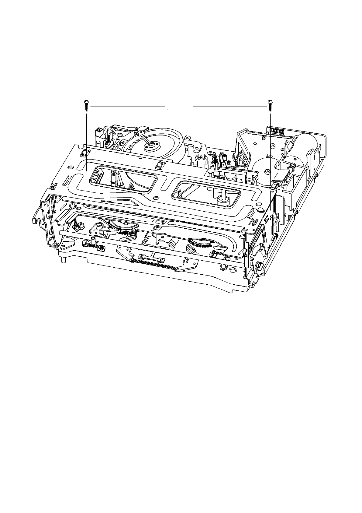
DISASSEMBLY AND REPLACEMENT ZERLEGEN UND ERSATZTEILEINBAU
FRONT LOADING ASSEMBLY REMOVAL ENTFERNEN DES FRONTLADE-BAUSATZES
NOTE: The FRONT LOADING ASSEMBLY can be
removed only in the eject position.
1) Remove the two screws as displayed in Fig.16 below. 1) Entfernen Sie die beiden Schrauben wie in der Abb.16
A0400
HINWEIS: Der FRONTLADE-BAUSATZ kann nur in der
Eject-Position entfernt werden.
unten dargestellt.
Front loading assembly separation
Entfernen des frontlabe bausatzes
Fig.16.
Abb.16.
16
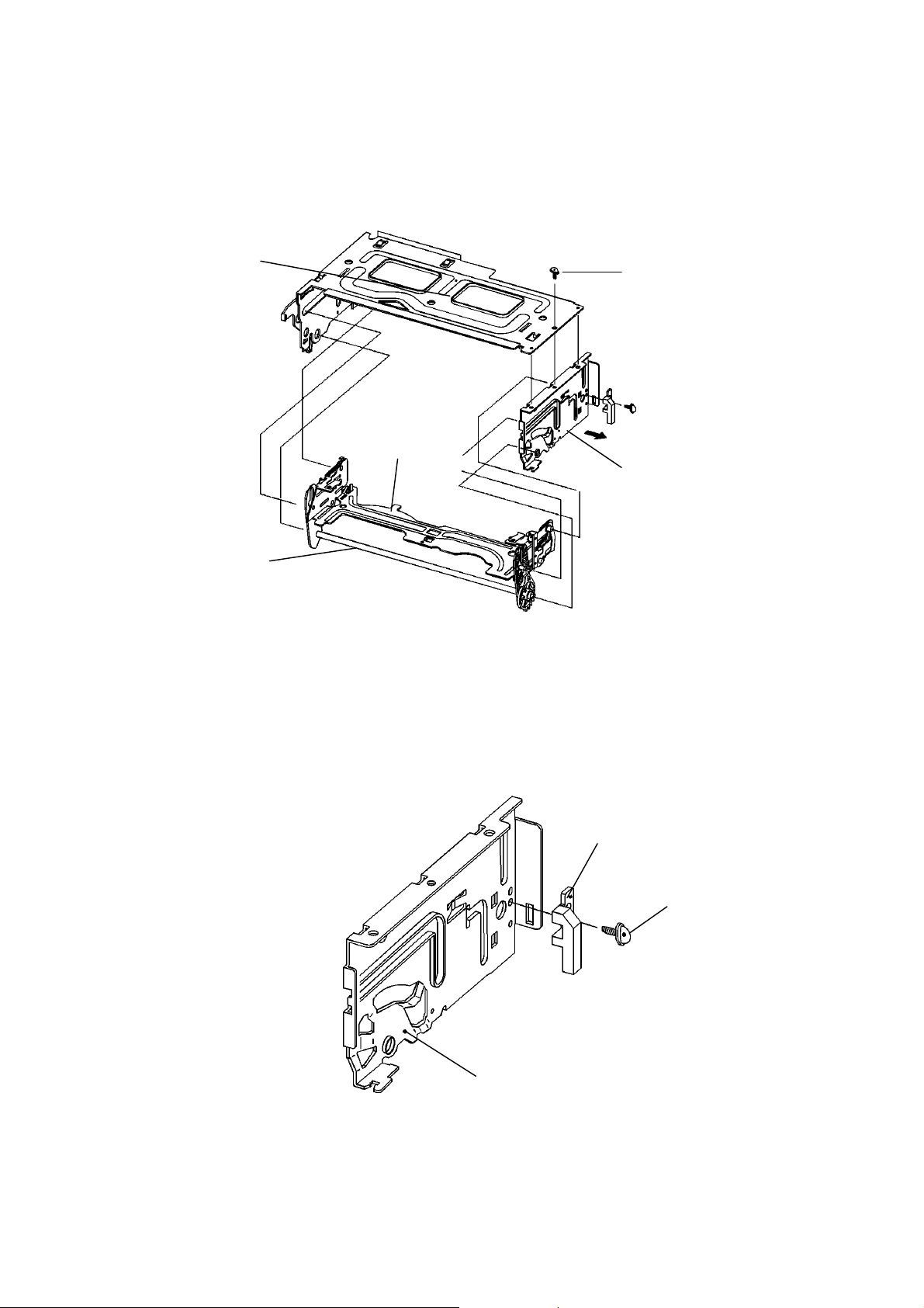
DISASSEMBLY OF THE VCR ZERLEGEN DES VCR
y
1) Remove the screw holding the F/L BRACKET R and
move the F/L BRACKET R in the direction of the arrow
to separate it from the TOP PLATE and CASSETTE
HOLDER ASSEMBLY.
2) Remove the CASSETTE HOLDER ASSEMBLY.
TOP PLATE ASS’Y
OBERER PLATTENBAUSATZ
CST HOLDER ASS’Y
KASSETTENHALTERBAUSATZ
LOADING LEVER
ASS’YLADEHEBEL-BAUSATZ
1) Entfernen Sie die Schraube, mit welcher die F/LKlammer R befestigt ist, und schieben Sie die F/LKlammer R in Richtung des Pfeils, um sie vom
OBEREN PLATTEN- und dem KASSETTENHALTERBAUSATZ zu trennen.
2) Entfernen Sie den KASSETTENHALTER-BAUSATZ.
SCREWS
SCHRAUBEN
F/L BRACKET ASS’Y
F/L-KLAMMER-BAUSATZ
Disassembly of the front loading bracket (right)
Zerlegen des frontladebausatzes
3) Remove the screw holding the PRISM LINK R and
remove the PRISM LINK R from the F/L BRACKET R.
Fig.17.
Abb.17.
3) Entfernen Sie die Schraube, mit welcher die
PRISMENVERBINDUNG R befestigt ist und entfernen
Sie die PRISMENVERBINDUNG R von der F/LKLAMMER R.
PRISM LINK R
PRISMENVERBINDUNG R
SCREW
SCHRAUBEN
F/L BRACKET
F/L-KLAMMER
Disassembly of the front loading assembl
Zerlegen der rechten frontlade-klammer
Fig.18.
Abb.18
17
DISASSEMBLY OF THE VCR (CONT.) ZERLEGEN DES VCR (FORTSTZG.)
y
4) Remove the screw holding the PRISM LINK L.
5) Release the hook B by pushing it in the direction of the
arrow and remove the DOOR OPENER.
4) Entfernen Sie die Schraube, mit welcher die
PRISMENVERBINDUNG L befestigt ist.
5) Klinken Sie den Haken B aus, indem Sie ihn in
Richtung des Pfeils dr üc ken und entf ernen Sie den
TÜRÖFFNER.
PRISM LINK L
PRISMENVERBINDUNG L
HOOK A
HAKEN A
HOOK B
HAKEN B
6) Remove the LOADING LEVER ASSEMBLY by
pressing the connected section of the LOADING
LEVER ASSEMBLY in the direction of the arrows.
7) Remove the SAFETY SPRING between the SAFETY
LEVER and the CASSETTE HOLDER PLATE.
8) Remove the RELEASE SPRING between the
RELEASE LEVER and the SAFETY LEVER R.
DOOR OPENER
TÜRÖFFNER
Disassembly of the top plate
Zerlegen der oberen Platte
SAFETY SPRING
SICHERHEITSFEDER
SCREW
SCHRAUBEN
TOP PLATE
OBERE PLATTE
Fig.19.
Abb.19.
6) Entfernen Sie den LADEHEBEL-BAUSATZ, indem Sie
auf den verbundenen Teil des Bausatzes in Richtung
der Pfeile drücken.
7) Entfernen Sie die SICHERHEITSFEDER zwischen
dem SICHERHEITSHEBEL und der
KASSETTENHALTERPLATTE.
8) Entfernen Sie die FREIGABEFEDER zwischen dem
FREIGABEHEBEL und dem SICHERHEITSHEBEL R.
SAFETY LEVER
SICHERHEITSHEBEL
LOADING LEVER AS
LADEHEBEL-BAUSATZ
SAFETY
LEVERSICHERHEITSHEBEL
CST HOLDER AS
KASSETTENHALTER-BAUSATZ
Disassembly of the cassette holder assembl
Zerlegen des kassettenhalter-bausatzes
Fig.20.
Abb.20.
18
RELEASE SPRING
FREIGABEFEDER
RELEASE LEVER
FREIGABEHEBEL

DISASSEMBLY OF THE VCR (CONT.) ZERLEGEN DES VCR (FORTSTZG.)
Ü
y
NOTE
Reassemble the FRONT LOADING MECHANISM in the
reverse order. Confirm that the two bosses on the left side
of the CASSETTE HOLDER are inserted into the groove
on the left side of the top plate.Insert the two bosses on the
right side of the cassette holder into the groove of the
FRONT LOADING BRACKET R.
TOP PLATE
OBERE PLATTE
Assembly of the F/L Assembl
Zusammenbau des F/L-Bausatzes
Fig.21.
Abb.21.
HINWEIS
Der FRONTLADEMECHANISMUS wird in umgekehrter
Reihenfolge wieder zusammengebaut. Stellen Sie dabei
sicher, daß die beiden Vorsprünge an der linken Seite des
KASSETTENHALTERS in die Rille an der linken Seite der
oberen Platte eingeführt werden. Die beiden Vorsprünge
an der rechten Seite des Kassettenhalters werden in die
Rille der FRONTLADEKLAMMER R eingeführt.
INSERT POINTS
HRPUNKTE
EINF
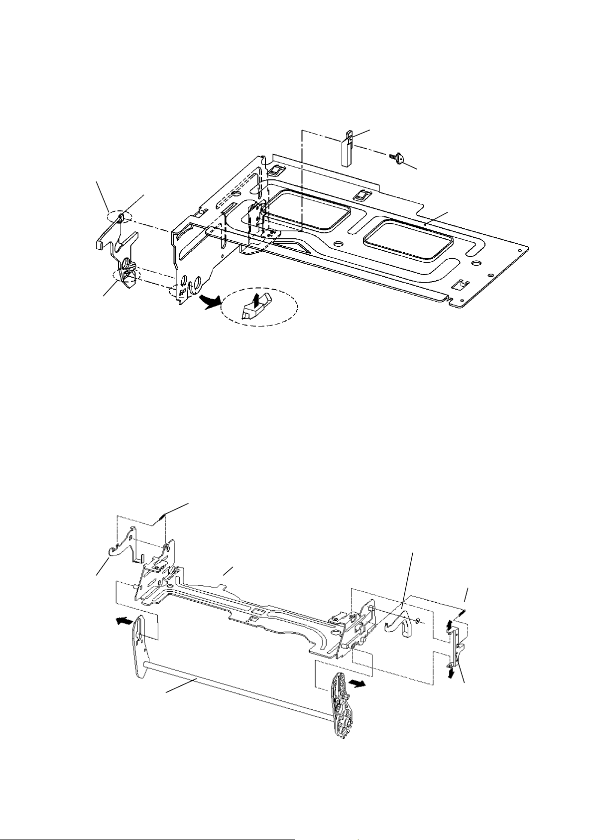
DRUM ASSEMBLY / EARTH
BRACKET ASSEMBLY REMOVAL
1) Remove three screws (1) fixing the DRUM TOTAL
ASSEMBLY.
2) Remove the EARTH BRACKET ASSEMBLY. (2)
3) Carefully lift the DRUM TOTAL ASSEMBLY. (3)
NOTE
1) After assembling the DRUM TOTAL ASSEMBLY,
confirm that the tape runs smoothly.
(Refer to ADJUSTMENT OF THE TAPE
TRANSPORTING SYSTEM).
2) When assembling the EARTH BRACKET
ASSEMBLY, a 3x12 screw should be used and
all other parts should use 3x10 screws, as indicated.
ENTFERNEN VON WALZENBAUSATZ
/ ERDKLEMMENBAUSATZ
1) Entfernen Sie die Schrauben (1), mit welchen der
WALZEN-GESAMTBAUSATZ befestigt ist.
2) Entfernen Sie den ERDKLEMMEN-BAUSATZ. (2)
3) Heben Sie den WALZEN-GESAMTBAUSATZ
vorsichtig heraus. (3)
HINWEIS
1) Nach Zusammenbau des WALZEN-GESAMTBAUSATZES ist
sicherzustellen, daß das Band gleichmäßig läuft. (Nehmen Sie
Bezug auf das Kapitel EINSTELLUNG DES
BANDTRANSPORTSYSTEMS).
2) Beim Zusammenbau des ERDKLEMMENBAUSATZES sollte eine
3x12 Schraube verwendet werden. Für alle anderen Teile sollten
3x10 Schrauben verwendet werden, wie in der Abb. dargestellt.
Drum total assembly and earth
bracket assembly removal.
Entfernen von walzenbausatz &
erdklemmenbausatz.
Fig.22.
Abb.22.
19
 Loading...