

Page 1

CONTROLLER / TUNER
®
R-STAND BY
POWER
G-
POWER
ON
MENU
ACTION INPUT
VOLUME
CHANNEL
INPUT 3
S-VIDEO
VIDEO
L-AUDIO-R
Operating Instructions
Model No.
IMPUT
N
TIO
AC
U
N
E
M
ON
R-STAND BY
ER
W
PO
R
G-
E
W
O
P
TU-PTA500U
R
-
O
I
D
U
A
-
L
INPUT 3
O
E
D
I
V
O
E
D
I
V
-
S
CHANNEL
VOLUME
For assistance, please call : 1-888-VIEW-PTV (843-9788)
or send e-mail to : consumerproducts@panasonic.com
or visit us at www.panasonic.co.jp/global/ (U.S.A)
For assistance, please call : 787-750-4300
(Puerto Rico)
For assistance, please call : 1-800-561-5505
or visit us at www.panasonic.co.jp/global/ (Canada)
Before connecting, operating or adjusting this product, please read these instructions completely. Save this manual for
future reference.
TQBC0216
Page 2

WARNING
RISK OF ELECTRIC SHOCK
DO NOT OPEN
WARNING: To reduce the risk of electric shock do not remove cover or back. No
user-serviceable parts inside. Refer servicing to qualified service personnel.
The lightning flash with
arrow-head within a triangle
is intended to tell the user
that parts inside the
product are a risk of electric
shock to persons.
WARNING: To prevent damage which may result in fire or shock hazard, do not expose this appliance to
rain or moisture.
To prevent electric shock, do not remove cover. No user serviceable parts inside. Refer servicing to
qualified service personnel.
The exclamation point within
a triangle is intended to tell
the user that important
operating and servicing
instructions are in the
papers with the appliance.
Important Safety Instructions
Read these instructions
All the safety and operating instructions shall be read before the appliance is operated.
Keep these instructions
The safety and operating instructions shall be retained for future reference.
Heed all warnings
All warnings on the appliance and in the operating instructions shall be adhered to.
Follow all instructions
All operating and use instructions shall be followed.
Water and Moisture
Do not use this product near water - for example, near a bath tub, wash bowl, kitchen sink, or laundry tub, in a wet
basement, or near a swimming pool, and the like.
Cleaning
Unplug this product from the wall outlet before cleaning. Do not use liquid cleaners or aerosol cleaners. Use a damp
cloth for cleaning.
Do not block any ventilation openings. Install in accordance with the manufacture’s instructions.
Slots and openings in the cabinet are provided for ventilation and to ensure reliable operation of the product and to
protect it from overheating, and these openings must not be blocked or covered. There shall be at least 4 inches (10
cm) of space from those opening.
The openings shall never be blocked by placing the product on a bed, sofa, rug, or other similar surface.
Do not install near any heat sources such as radiators, heat registers, stoves, or other apparatus (including
amplifiers) that produce heat.
This product shall never be placed near or over a radiator or heat register. This product shall not be placed in a built-in
installation such as a rack unless proper ventilation is provided or the manufacturer’s instructions have been adhered to.
Do not defeat the safety purpose of the polarized plug or the grounding-type plug. A polarized plug has two
blades with one wider than the other. A grounding-type plug has two blades and a third grounding prong. The
wide blade or the third prong are provided for your safety. If the provided plug does not fit into your outlet,
consult an electrician for replacement of the obsolete outlet.
Power Sources
This product shall be operated only from the type of power source indicated on the marking label. If you are not sure
of the type of power supply to your home, consult your appliance dealer or local power company.
Unplug this apparatus during lightning storms or when unused for long period of time.
2
Page 3

Important Safety Instructions
Power-Cord Protection
Power-supply cords shall be routed so that
EXAMPLE OF ANTENNA GROUNDING AS
PER (NEC) NATIONAL ELECTRICAL CODE
they are not likely to be walked on or pinched
by items placed upon or against them, paying
particular attention to cords at plugs,
ANTENNA
LEAD-IN WIRE
convenience receptacles, and the point where
they exit from the appliance.
GROUND
CLAMP
Attachments
Do not use attachments / accessories not
recommended by the product manufacturer as
they may cause hazards.
This product shall be operated only from the
type of power source indicated on the marking
label. If you are not sure of the type of power
supply to your home, consult your appliance
dealer or local power company.
Unplug this apparatus during lightning storms
ELECTRIC
SERVICE
EQUIPMENT
GROUND CLAMPS
POWER SERVICE GROUNDING
ELECTRODE SYSTEM
(NEC ART 250, PART H)
ANTENNA DISCHARGE
UNIT (NEC SELECTION
810 – 20)
GROUNDING
CONDUCTORS (NEC
SELECTION 810 – 21)
or when unused for long period of time.
Accessories
Use only with the cart, stand, tripod, bracket, or table specified by the manufacturer, or sold with
the apparatus. When a cart is used, use caution when moving the cart / apparatus combination to
avoid injury from tip-over.
Quick stops, excessive force, and uneven surfaces may cause the appliance and cart combination to overturn.
Unplug this apparatus during lightning storms or when unused for long periods of time.
This will prevent damages to the product due to Lightning and power-line surges.
Refer all servicing to qualified service personnel. Servicing is required when the apparatus has been damaged in
any way, such as power-supply cord or plug is damaged, liquid has been spilled or objects have fallen into the
apparatus, the apparatus has been exposed to rain or moisture, does not operate normally, or has been dropped.
Overloading
Do not overload wall outlets and extension cords as this can result in a risk of fire or electric shock.
Object and Liquid Entry
Never push objects of any kind into this product through openings as they may touch dangerous voltage points or
short-out parts that could result in a fire or electric shock. Never spill liquid of any kind on the product.
Servicing
Do not attempt to service this product yourself as opening or removing covers may expose you to dangerous voltage
or other hazards. Refer all servicing to qualified service personnel.
Replacement Parts
When replacement parts are required, be sure the service technician has used replacement parts specified by the
manufacturer or have the same characteristics as the original part. Unauthorized substitutions may result in fire,
electric shock or other hazards.
Safety Check
Upon completion of any service or repairs to this product, ask the service technician to perform safety checks to
determine that the product is in proper operating condition.
Damage Requiring Service
Unplug this product from the wall outlet and refer servicing to qualified service personnel under the following
conditions:
a. When the power-supply cord or plug is damaged.
b. If liquid has been spilled, or objects have fallen into the product.
c. If the product does not operate normally by following the operating instructions. Adjust only those controls that are
covered by the operating instructions as an improper adjustment of other controls may result in damage and will
often require extensive work by a qualified technician to restore the product to its normal operation.
d. If the product has been dropped or the cabinet has been damaged.
3
Page 4

Important Safety Instructions
e. When the product exhibits a distinct change in performance - this indicates a need for service.
f. If the product has been exposed to rain or water.
Installation
This unit Location
Adequate ventilation is essential to prevent internal component failure. Keep away from areas of excessive heat or moisture.
Optional External Equipment
The Video / Audio connection between components can be made with shielded video and audio cables. For best performance,
video cables should utilize 75 Ω coaxial shielded wire. Cables are available from your dealer or electronic supply house.
Before you purchase any cables, be sure you know what type of output and input connectors your various components require.
Also determine the length of cable you’ll need.
AC Power Supply Cord
CAUTION: To prevent electric shock, match wide blade of plug to wide slot of AC outlet and fully insert. Do not use
this (polarized) plug with a receptacle or other outlet unless the blade can be fully inserted to prevent
blade exposure.
Do not place this unit upside down or in a vertical position.
Do not install and use this unit upside down.
Do not install and use this unit standing on its side.
FCC STATEMENT
Notes:
This equipment has been tested and found to comply with the limits for a Class B digital device, pursuant to part 15 of
the FCC Rules. These limits are designed to provide reasonable protection against harmful interference in a
residential installation. This equipment generated, uses, and can radiate radio frequency energy and, if not installed
an used in accordance with the instructions, may cause harmful interference to radio communications. However, there
is no guarantee that interferernce will not occur in a particular installation. If this equipment does cause harmful
interference to radio or television reception, which can be determined by turning the equipment off and on, the user is
encouraged to try to correct the interference by one or more of the following measures:
• Reorient or relocate the receiving antenna.
• Increase the separation between the equipment and receiver.
• Connect the equipment into an outlet on a circuit different from that to which the receiver is connected.
• Install the CONTROLLER/TUNER at least 15.7 inch (40 cm) away from the Wide Plasma Display to avoid interference.
• Consult the dealer or an experienced radio/TV technician for help.
FCC CAUTION:
Pursuant to 47CFR, Part 15.21 of the FCC rules, any changes or modifications to this device not expressly
approved by Matsushita Electric Corporation of America could cause harmful interference and would void the
user’s authority to operate this device.
Responsible Party:
This device complies with Part 15 of the FCC Rules. Operation is subject to the following two conditions: (1) This
device may not cause harmful interference, and (2) this device must accept any interference received, including
interference that may cause undesired operation.
CANADIAN NOTICE:
This Class B digital apparatus complies with Canadian ICES-003.
FCC Declaration of Conformity
TU-PTA500U
Matsushita Electric Corporation of America
One Panasonic Way Secaucus. NJ 07094
1-800-528-8601
4
Page 5

Dear Panasonic Customer
Welcome to the Panasonic family of customers. We hope that you will have many years of
enjoyment from your new Controller / Tuner set.
To obtain maximum benefit from your set, please read these Instructions before making any
adjustments, and retain them for future reference.
Retain your purchase receipt also, and note down the model number and serial number of your
set in the space provided on the rear cover of these instructions.
For assistance, please call : 1-888-VIEW-PTV (843-9788)
or send e-mail to : consumerproducts@panasonic.com
or visit us at www.panasonic.co.jp/global/ (U.S.A)
For assistance, please call : 787-750-4300
For assistance, please call : 1-800-561-5505
or visit us at www.panasonic.co.jp/global/ (Canada)
Table of Contents
Important Safety Instructions ......................................2
FCC STATEMENT ..........................................................4
Installation .....................................................................6
ACCESSORIES ...........................................................6
Remote Control battery installation..............................6
Controls and terminals on the CONTROLLER / TUNER .....
Connecting the antenna cable to the RF In Terminal....
Antenna / cable connection..........................................8
How to connect this unit and Wide Plasma Display ......
How to connect the OUTPUT Terminals .................... 11
How to connect the AUDIO OUT Terminals ............... 11
How to connect the “1, 2” Input Terminals .................12
How to connect the Input 3 Terminals ........................12
How to connect
the COMPONENT VIDEO INPUT Terminals ....
How to connect the PC Input Terminals .....................14
Power ON / OFF and Input Signal Selection.............15
Connecting the Plug to the Wall Outlet ......................15
Power ON / OFF ........................................................15
Location of Controls ...................................................16
Flow Chart of Main menu ...........................................18
Tuning channels (Automatic channel programming) ...
Tuning channels (Manual channel programming).......21
ASPECT Controls........................................................22
VHF, UHF and CATV ....................................................24
Cable TV.......................................................................25
Selection input signal .................................................26
Recall ...........................................................................27
10
13
20
(Puerto Rico)
Adjusting screen POSITION/SIZE(TV,VIDEO input mode)...
Adjusting PICTURE POS./SIZE (PC input mode) .......30
SOUND Adjustments (
AUDIO Adjustments (PC input mode).........................33
Mute..............................................................................33
7
Picture Adjustments
8
Picture Adjustments (PC input mode) ........................36
SURROUND Controls .................................................37
Closed Captions..........................................................38
Lock Feature................................................................40
Customizing the VIDEO INPUT labels .......................43
Selecting STEREO / SAP / MONO..............................45
Using the OFF-TIMER .................................................45
Optimizing display for DVC recording mode
Adjusting unnatural video images (3D Y/C FILTER) ....
Automatically changing screen size
Cancelling automatic enlarging of screen................49
Setting when 480p signals (sequential scan) are
Switching languages for display ...............................51
SET UP for PC Input Signals......................................52
Operating peripheral equipment using the remote control....
Troubleshooting..........................................................61
Specifications..............................................................63
(for TV, VIDEO input mode)..............................34
(DVC PLAYBACK MODE) ...............................46
for VIDEO INPUT modes ...............................48
input through COMPONENT VIDEO INPUT ....
TV,
VIDEO input mode) ............32
28
47
50
53
5
Page 6
Installation
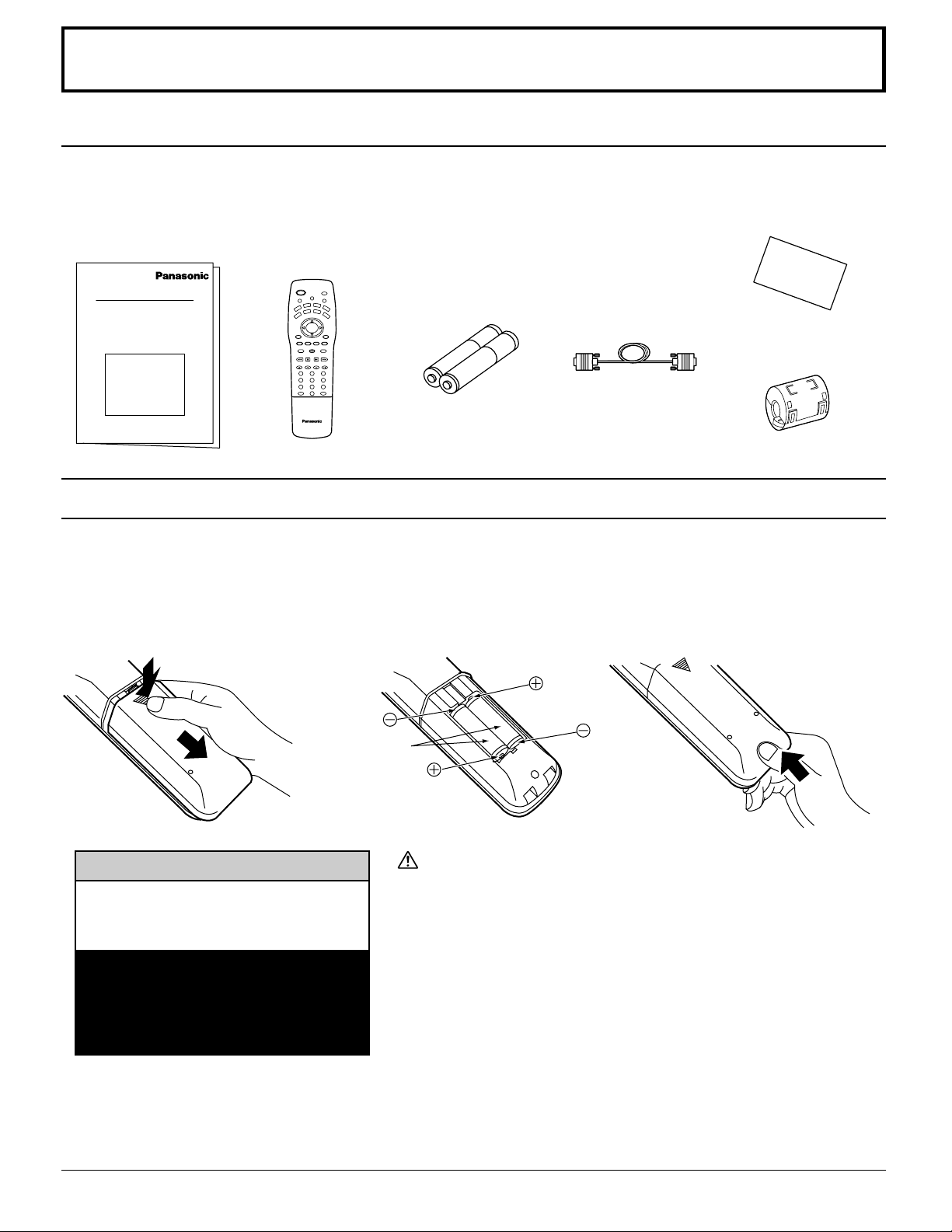
ACCESSORIES
Check the accessories before installations.
Operating
•
Instruction book
TQBC0216
Remote Control
•
Transmitter
EUR511164
LIGHT
POWER
ASPECT
MUTE TV/VIDEO
A
U
D
X
V
D
RCVR
VCR
C
BL
DTV
DBS
V
CH
T
ACTION
VOL VOL
MENU
INFO/RECALL
CH
OFF TIMER
PC
NORMAL
SURROUND
GUIDE
VCR REC
EXIT
FF
REW
PLAY
STOP
VCR/DBS CHANNEL
PAUSE
TV/VCR
OPEN/CLOSE STILL
SLOW
123
456
789
R-TUNE PROG
0
Battery for the Remote
•
Control Transmitter
(2 × AA (IEC R6) size)
Remote control battery installation
Requires two AA batteries.
1. Turn the transmitter face down.
Remove top cover by pressing
down on marking and sliding
cover off in the direction
indicated.
2. Install the batteries as shown in
the battery compartment.
(Polarity + or – must match the
markings in the compartment).
Display Cable
•
Warranty Card
•
K1HA26FA0001
Ferrite Core
•
TSK1027
3. Replace the cover and slide in
reverse until the lock snaps.
Two AA size
Helpful Hint:
For frequent remote control users,
replace old battery with Alkaline
batteries for longer life.
Note: In order to maximize the life of
the batteries, the lighted buttons on
the Remote Control can be turned
OFF and ON by pressing R-TUNE
and RECALL at the same time.
Precaution on battery use
Incorrect installation can cause battery leakage and corrosion that will
damage the remote control transmitter.
Observe the following precautions:
1. Batteries should always be replaced as a pair. Always use new
batteries when replacing the old set.
2. Do not combine a used battery with a new one.
3. Do not mix battery types (example: “Zinc Carbon” with “Alkaline”).
4. Do not attempt to charge, short-circuit, disassemble, heat or burn
used batteries.
5. Battery replacement is necessary when remote control acts
sporadically or stops operating this unit.
Helpful Hint:
Whenever you remove the batteries, you may need to reset the remote control infrared codes. We recommend
that you record the code on page 54 – 57, prior to setting up the remote.
6
Page 7
Installation
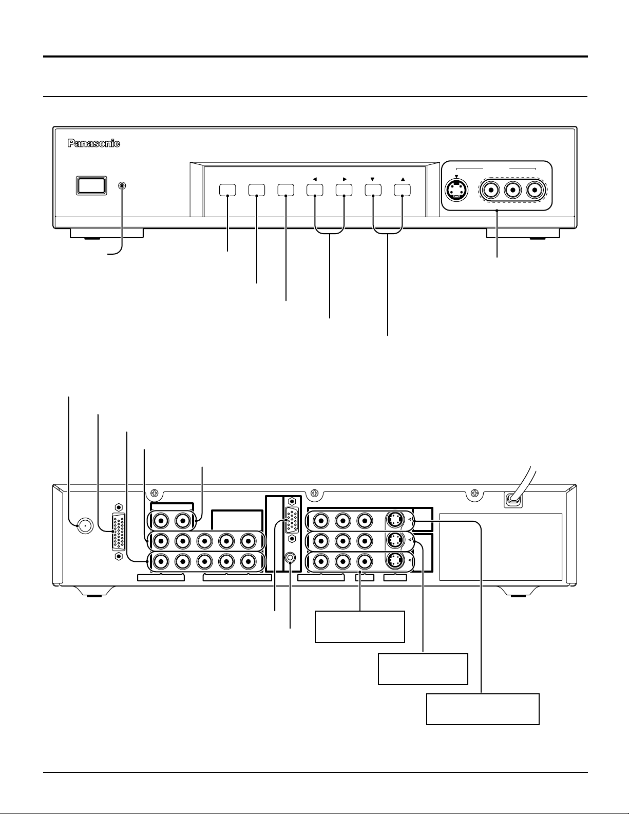
Controls and terminals on the CONTROLLER / TUNER
CONTROLLER/TUNER TU-PTA500U
R-STAND BY
POWER
G-
POWER
ON
POWER
Indicator
(see page 15)
Menu button
(see page 18)
Action button (see page 19)
Input mode selection buttons (see page 26)
Volume up (+) / down (–) buttons (see page 18)
Program number selection buttons (see page 19)
RF Input terminal (see page 8 – 9)
DISPLAY OUT terminal (see page 10)
COMPONENT 2 VIDEO INPUT (see page 13)
COMPONENT 1 VIDEO INPUT (see page 13)
AUDIO OUT (see page 11)
MENU
ACTION INPUT
VOLUME
CHANNEL
S-VIDEO
INPUT 3
VIDEO
Input 3 terminals
Video camera cable
terminal
L-AUDIO-R
ANT
AUDIO OUT
COMPONENT
VIDEO INPUT
1
DISPLAY OUT
AUDIO R - L
PR - PB - Y VIDEO
2
PC RGB Input terminal (see page 14)
PC Audio Input terminal (see page 14)
OUTPUT
-
IN
PC
1
2
AUDIO R
-
L
VIDEO
INPUT
S-VIDEO
Input 2 terminals
(see page 12)
Input 1 terminals
(see page 12)
VIDEO OUT terminals
(see page 11)
7
Page 8
Installation
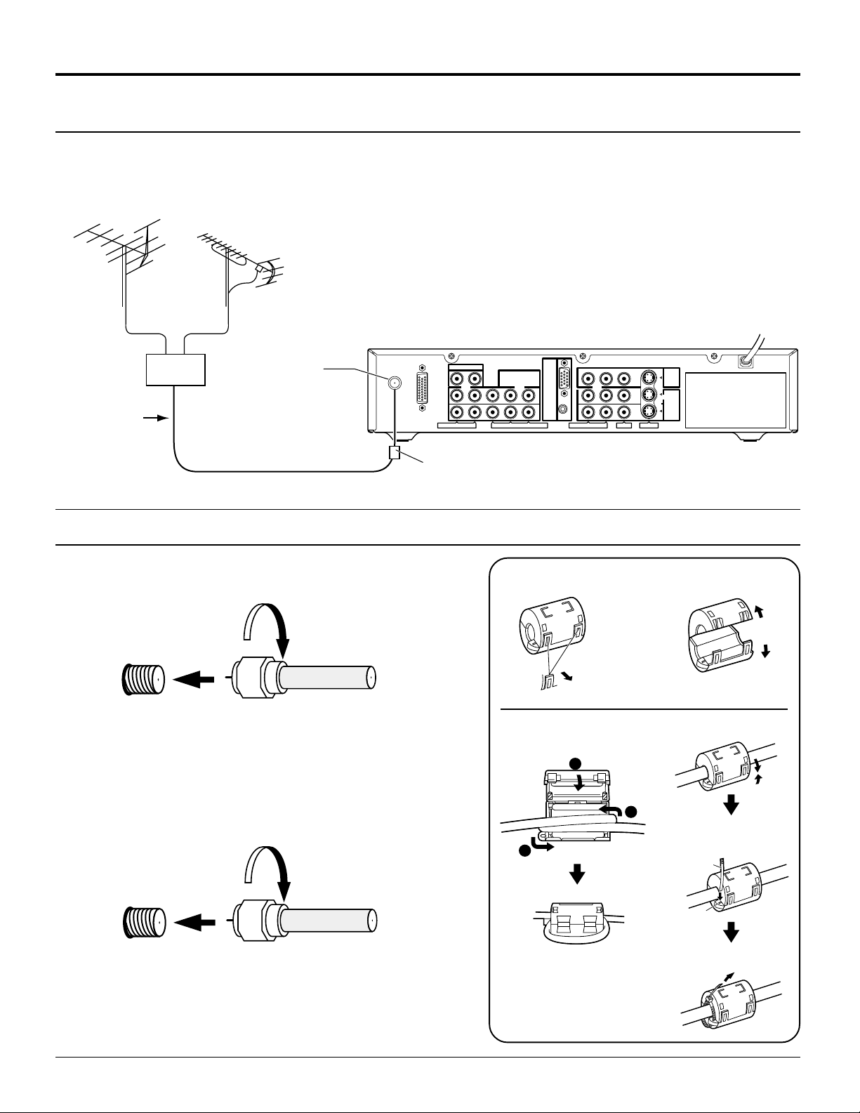
Connecting the antenna cable to the RF In Terminal
Antenna Connection - For proper reception of VHF / UHF channels, an external antenna is required. For best
reception an outdoor antenna is recommended. Antenna Mode must be set to this unit.
VHF Antenna UHF Antenna
ANT
DISPLAY OUT
75 Ω
Mixer
RF In Terminal
Coaxial Cable
Antenna / cable connection
Incoming Cable From Home Antenna (75 Ω)
VHF / UHF
on Back of Set
Cable Connection - For reception of cable channels (01 – 125)
connect the cable supplied by your local cable company. Antenna
Mode must be set to CABLE. (Refer to Antenna Mode section.)
AUDIO OUT
AUDIO R - L
COMPONENT
VIDEO INPUT
R
- PB - Y VIDEO
P
PC
-
IN
1
2
Ferrite sleeve (Supplies)
Installing the ferrite sleeve
12
3
Pass the cable
through and close
1
2
AUDIO R - L
VIDEO
Pull back the
tabs
(in two places)
3
OUTPUT
INPUT
S-VIDEO
Open
(For a thick cable)
Incoming 75 Ω Cable (From Cable Company)
VHF / UHF
on Back of Set
Note:
Certain cable systems offset some channels to reduce interference
or have Premium (scrambled) channels. A cable converter box is
required for proper reception. Check with your local Cable company
for its compatibility requirements.
8
2
Pass the clamper
1
through the hole.
Clamper
Hole
Tighten the clamper to
secure the cable.
Page 9
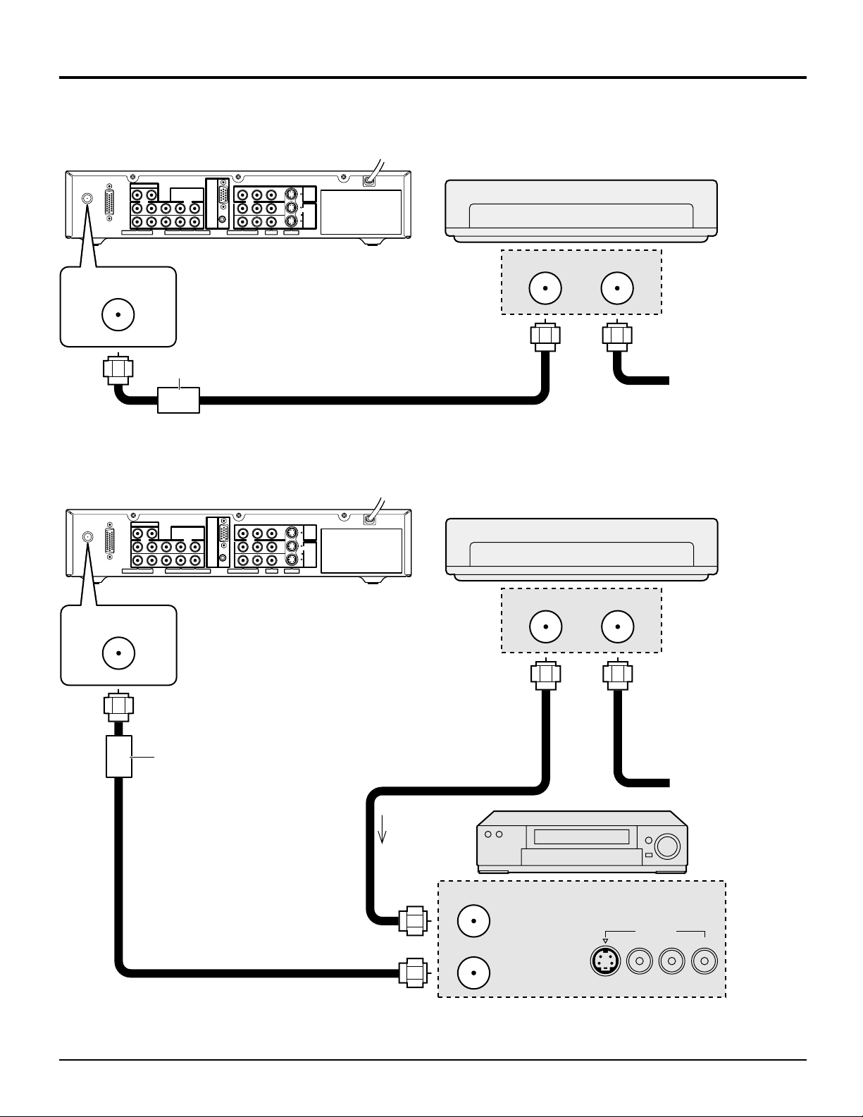
Installation
Antenna Connection (Cable Box, no VCR)
Use this configuration when connecting this unit to a cable TV system using a Cable Box.
CABLE BOX
DISPLAY OUT
ANT
AUDIO OUT
AUDIO R - L
ferrite sleeve
COMPONENT
VIDEO INPUT
-
IN
PC
1
2
P
R
- PB - Y VIDEO
ANTENNA
TERMINAL ON
THE BACK OF
THIS UNIT.
1
2
AUDIO R
-
L
OUTPUT
INPUT
VIDEO
S-VIDEO
Connect the cable from the Output
terminal on the back of the Cable
Box to the ANT terminal on the
back of this unit.
OUTPUT INPUT
ANT
Antenna Connection (Cable Box, and VCR)
Use this configuration when connecting this unit to a cable TV system using a Cable Box and VCR.
TERMINAL
ON BACK OF
CABLE BOX
Incoming Cable from
Antenna or Cable TV
System
ANT
AUDIO OUT
COMPONENT
VIDEO INPUT
-
IN
PC
1
1
2
DISPLAY OUT
ANT
AUDIO R - L
R
- PB - Y VIDEO
P
ANTENNA
2
AUDIO R
-
TERMINALS
ON THE BACK
OF THIS UNIT.
ferrite sleeve
Connect the cable from the Output
terminal on the back of the VCR to
the Antenna input terminal on the
back of this unit.
CABLE BOX
OUTPUT
INPUT
VIDEO
L
S-VIDEO
TERMINAL
ON BACK OF
CABLE BOX
OUTPUT INPUT
Connect the cable from the
Output terminal on the back
of the Cable Box to the
Antenna input terminal on
Connect the cable from the
antenna or cable system to
the Input terminal on the
back of the CABLE BOX.
the back of the VCR.
Incoming Cable from
Antenna or Cable TV
VCR
System
TO VCR
ANT INPUT
OUTPUT
ANT OUTPUT
S-VIDEO
VIDEO
L-AUDIO-R
Note: When the antenna cable is connected to this unit antenna terminal via a cable box or VCR, set this unit channel
to CH3 or CH4, cable. This does not apply when signal is input from VIDEO INPUT.
9
Page 10
Installation
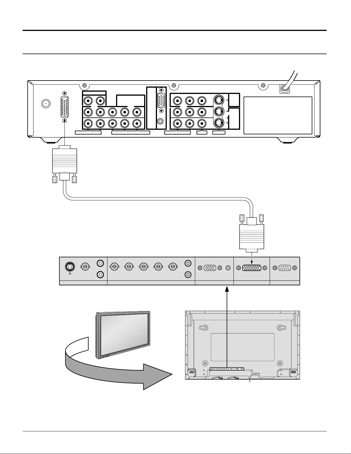
How to connect this unit and Wide Plasma Display
ANT
DISPLAY OUT
AUDIO OUT
AUDIO R - L
P
L
COMPONENT
VIDEO INPUT
PC
-
IN
1
2
R
- PB - Y VIDEO
Display cable (Supplied)
1
2
AUDIO R
-
L
OUTPUT
INPUT
VIDEO
S-VIDEO
L
S-VIDEO
AUDIO AUDIO
VIDEO
R
+
L
O
V
—
T
U
P
N
I
Y
B
D
N
A
/
T
S
-
N
O
R
R
E
R
E
W
W
O
O
P
P
G
VD HD P
R/CR
/R PB/CB/B Y/G
R
AUDIO
PC INCOMPONENT/RGB IN
SERIALTUNER IN
Back view of Wide Plasma Display
Notes:
Install the CONTROLLER/TUNER at least 15.7 inch (40 cm) away from the Wide Plasma Display to avoid interference.
Be sure the power to the Wide Plasma Display and CONTROLLER/TUNER is OFF before connecting cables.
10
Page 11

How to connect the OUTPUT Terminals
Installation
VCR
S-Video
IN
Video
IN
L
Audio
IN
R
AUDIO
Video Monitor
INPUT
—
VOL
+
R - STANDBY
G POWER ON
Note:
The video signal input to the COMPONENT input and PC input will not be
output from the output terminal.
Connect to the S-VIDEO or Video terminals.
S-VIDEO cable
VIDEO
OUTPUT
OUTPUT
1
2
AUDIO R - L
VIDEO
S-VIDEO
INPUT
How to connect the AUDIO OUT Terminals
Used for connecting external amplifiers.
AUDIO
L
R
Amplifier to speaker system
Note:
The AUDIO OUT terminals output a fixed audio signal.
(SOUND ADJUST, VOLUME UP/DOWN and SURROUND ON/OFF are not
functional for output signals from the AUDIO OUT terminals.)
-
AUDIO R
AUDIO R - L
L
AUDIO OUT
COMPONENT
VIDEO INPUT
P
R
- PB - Y VIDEO
1
2
11
Page 12

Installation
How to connect the “1, 2” Input Terminals
Connects VCRs and other peripheral equipment (INPUT 1, 2)
(Example) When connecting a S-VIDEO VCR
S-VIDEO VCR
S-Video
OUT
Video
OUT
L
Audio
OUT
R
(Example) When connecting the Composite Video connector.
VIDEO VCR
S-VIDEO cable
2 × RCA
audio cable
AUDIO R - L
VIDEO cable
INPUT
OUTPUT
1
2
VIDEO
S-VIDEO
INPUT
Video
OUT
Audio
OUT
L
R
2 × RCA
audio cable
1
2
AUDIO R - L
VIDEO
INPUT
OUTPUT
INPUT
S-VIDEO
Notes:
(1) When a monaural VCR is used, connect the monaural audio cable to the AUDIO-L (Left) terminal.
(2) Similar connections are available at the INPUT 1, 2, 3 input terminals.
Input 3 is located on the front of the unit.
Select the desired VIDEO input position by pushing the TV/VIDEO button. (See page 26)
(3) When connecting video cables, priority is given to the S-Video cable when the S-Video input terminal and the video
input terminal are connected at the same time.
12
Page 13

How to connect the Input 3 Terminals
Installation
S-VIDEO
INPUT 3
INPUT 3
VIDEO
L-AUDIO-R
L-AUDIO-R
A video camera uses the
Video Input 3 terminal on
R-STAND BY
POWER
G-
POWER
ON
MENU
Connect the S-VIDEO or
VIDEO terminal.
ACTION INPUT
VOLUME
CHANNEL
S-VIDEO VIDEO
the front of this unit.
S-VIDEO Cable
VIDEO
Video camera
AUDIO
How to connect the COMPONENT VIDEO INPUT Terminals
DVD player
DVD (Y/PB/PR)
Y
B
P
P
R
AUDIO
L
R
2 × RCA
audio cable
AUDIO R
AUDIO R - L
-
L
AUDIO OUT
P
R
- PB - Y VIDEO
COMPONENT
VIDEO INPUT
P
R
- PB - Y VIDEO
COMPONENT
1
VIDEO INPUT
1
2
Note:
COMPONENT VIDEO INPUT
In order to prevent colors from interfering, image signals are divided into three signals of brightness, red and blue
(green is created automatically from these three signals). Each signal is processed from its own circuit and combined
on the screen, creating a natural picture.
13
Page 14

Installation
How to connect the PC Input Terminals
Computer
R-STAND BY
POWER
G-
POWER
ON
MENU
Conversion adapter (if necessary)
ACTION INPUT
VOLUME
CHANNEL
INPUT 3
S-VIDEO
VIDEO
L-AUDIO-R
D-sub 15p
PC-IN
RGB
PC cable
Connect a cable which matches the
1/8” (3 mm) stereo plug
audio output terminal on the computer.
Notes:
(1) Computer signals which can be input are those with a horizontal scanning frequency of 15.5 to 110 kHz and vertical
scanning frequency of 48 to 120 Hz. (However, signals exceeding 1200 lines will not be displayed properly.)
(2) The display resolution is a maximum of 640 × 480 dots when the aspect mode is set to “NORMAL”, and 852 × 480
dots when the aspect mode is set to “FULL”. If the display resolution exceeds these maximums, it may not be
possible to show fine detail with sufficient clarity.
(3) Some PC models cannot be connected to the set.
(4) An adapter is required to use the PC cable (D-sub 15P) to connect a Macintosh computer to the set.
(5) There is no need to use an adapter for computers with DOS/V compatible D-sub 15P terminal.
(6) The computer shown in the illustration is for example purposes only.
(7) Additional equipment and cables shown are not supplied with this set.
(8) Do not set the horizontal and vertical scanning frequencies for PC signals which are above or below the specified
frequency range.
Signal Names for D-sub 15P Connector
Pin No.
1514131211
67839
1
2
10
45
Pin layout for PC input
terminal
1
2
3
4
5
14
Signal Name
R
G
B
GND (Ground)
GND (Ground)
Pin No.
6
7
8
9
10
Signal Name
GND (Ground)
GND (Ground)
GND (Ground)
NC (not connected)
GND (Ground)
Pin No.
11
12
13
14
15
Signal Name
GND (Ground)
NC
HD / SYNC
VD
NC
Page 15

Power ON / OFF and Input Signal Selection
Power ON / OFF
Connect the plug to the Wall Outlet
Push the POWER switch on this unit to turn the set on
R-STAND BY
POWER
G-
POWER
ON
POWER
Power Indicator
MENU
R-STAND BY
G-
POWER
ACTION INPUT
ON
VOLUME
CHANNEL
INPUT 3
S-VIDEO
VIDEO
L-AUDIO-R
POWER-ON
Power Indicator: Green
Example: The screen below is displayed for a while after
this unit is turned on. (setting condition is an
example.)
For VIDEO / COMPONENT / TV INPUT:
CH123
STEREO
SAP
MONO
NORMAL
AUX
CBL
CH
CH
OFF TIMER
PLAY
LIGHT
RCVR
INFO/RECALL
PC
GUIDE
FF
PAUSE
POWER
MUTE TV/VIDEO
VCR
TV
VOL VOL
MENU
SURROUND
TV/VCR
OPEN/CLOSE STILL
D
DTV
NORMAL
EXIT
REW
STOP
VCR/DBS CHANNEL
ASPECT
D
V
ACTION
VCR REC
SLOW
123
DBS
POWER
For PC INPUT:
PC
NORMAL
Press the POWER button on the remote control to turn this
unit off
Power Indicator: Red (standby)
Press the POWER button on the remote control to turn this
unit on
Power Indicator: Green
Turn the power to this unit set off by pressing this power
switch on this unit, when this unit is on or in standby mode.
15
Page 16

Location of Controls
Illuminated Remote Control
Power button
Press to turn this unit ON or OFF. (See page 15)
Note:
The CONTROLLER / TUNER’s power cord must first be plugged
into the wall outlet and then turned on at the POWER switch.
MUTE button
Push this button to mute the sound. (See page 33)
Mode Selection buttons
Selects the operation mode for the remote control. (See page 53 – 60)
Digital Video Disk Mode Selection for
Remote Control
DVD
VCR Mode Selection for Remote Control
TV Mode Selection for Remote Control Digital Broadcasting Satellite
Digital TV Mode Selection for Remote Control
Operating of other Device
Buttons
VCR
CABLE / DBS
DVD / LD / CD
RCVR
REW
Skip Search
REW
Surround –
VCR
DTV
TV
STOP
STOP
Aux Mode Selection for
Remote Control
AUX
RCVR
CBL
DBS
Cable TV Mode Selection for Remote Control
PLAY
PLAY
Receiver / Amplifier Mode
Selection for Remote Control
for Remote Control
FF
Skip Search
FF
Surround +
CABLE / DBS
DVD / LD / CD
16
Buttons
VCR
RCVR
TV/VCR switch
Open/Close
Channel down
Channel down
Slow - / LD-sideB
/ Random
Center –
Channel up
Channel up
Slow - / LD-sideA
/ Repeat
Center +
Pause
Still/Pause
R-TUNE
R-TUNE button
Switches to previously view to
channel or video mode.
Page 17

ASPECT button
Change of screen size (See page 22).
Location of Controls
Panasonic AUTO NORMAL JUST
AUX
CBL
OFF TIMER
PLAY
LIGHT
RCVR
DBS
INFO/RECALL
PC
GUIDE
FF
PAUSE
POWER
MUTE TV/VIDEO
VCR
TV
VOL VOL
MENU
SURROUND
REW
TV/VCR
OPEN/CLOSE STILL
DVD
DTV
ACTION
NORMAL
VCR REC
EXIT
STOP
VCR/DBS CHANNEL
ASPECT
CH
CH
SLOW
123
456
FULL ZOOM
Lights the remote control buttons
The selected button blinks when lit.
TV/VIDEO buttons
This input mode changes each time this button is pressed. (See page 26)
Reduces volume
Moves cursor to
the left during
menu mode.
Displays menu
Press the Menu
button to display
the Menu screen.
MENU
ADJUST
SET UP
PICTURE
PICTURE ADJUST
POSITION / SIZE
AUDIO
SOUND ADJUST
AUDIO MODE
SELECTPAGE
ACTION
EXIT
Turning ON and OFF the remote
control illumination
R-TUNE
+
INFO/RECALL
Changes to the next channel up
Moves cursor upward during menu
mode.
CH
VOL VOL
MENU
ACTION
INFO/RECALL
CH
Changes to the next
channel down
Moves cursor downward
during menu mode.
Remote control
illumination can be turned
ON and OFF by pressing
the INFO/RECALL button
while pressing the
R-TUNE button.
Increase volume
Moves cursor to the
right during menu
mode.
The screen below
is displayed for
10 seconds.
CH123
STEREO
SAP
MONO
NORMAL
789
R-TUNE PROG
PROG
PROG button
0
NORMALIZATION button
Each setting in the MENU screen
is reset to its standard values.
(PICTURE, AUDIO, POSITION/SIZE).
SURROUND
button
(See page 33, 37)
SURROUND
EXIT
NORMAL
VCR REC
Returns to normal
viewing from the
MENU screen.
Previous before
VCR Record button
OFF TIMER button
(See page 45)
PC button
OFF TIMER
PC
GUIDE
Switches to the PC
INPUT mode.
GUIDE button
for DBS.
item in MENU.
Direct program number
selection buttons
17
Page 18

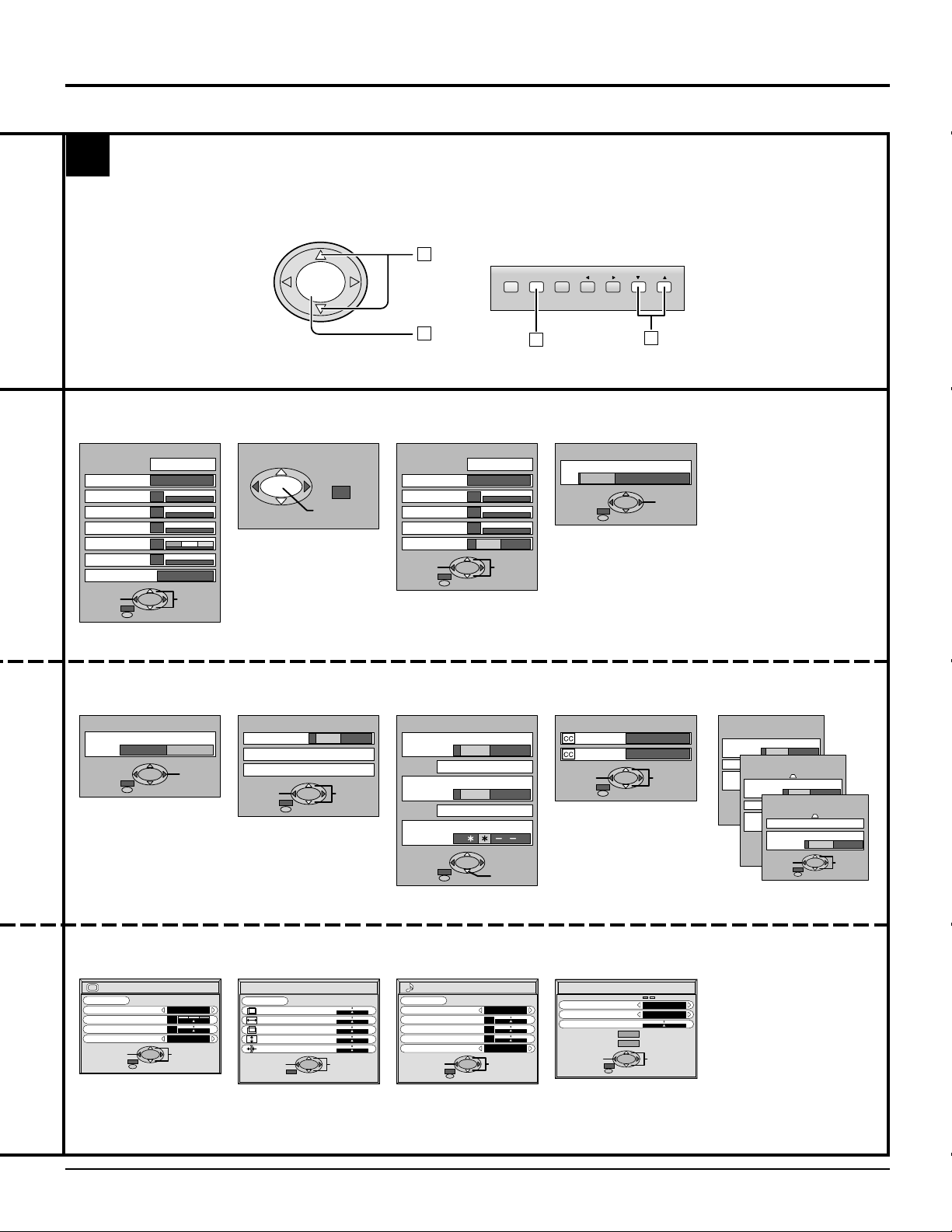
Flow Chart of Main menu
CH
VOL VOL
CH
ACTION
AU
CBL
CH
CH
OFF TIMER
PLAY
SLOW
LIGHT
X
INFO/RECALL
GUIDE
PAUSE
RCVR
PC
FF
POWER
ASPECT
MUTE TV/VIDEO
DVD
VCR
DTV
TV
VOL VOL
ACTION
MENU
NORMAL
SURROUND
VCR REC
EXIT
REW
STOP
VCR/DBS CHANNEL
TV/VCR
OPEN/CLOSE STILL
123
456
789
R-TUNE PROG
0
DBS
If the MENU button is pressed, the
1 2
MENU screen will be displayed.
If the MENU button is pressed once more
while the menu screen is displayed, the
MENU screen will be cleared.
The MENU button on the unit can
MENU
also be pressed to display the
MENU screen.
ACTION INPUT
MENU MENU ACTION INPUT
VOLUME
CHANNEL
During TV, VIDEO 1 – 3
and COMPONENT 1 – 2
input mode
MENU
ADJUST
PICTURE ADJUST
POSITION / SIZE
SOUND ADJUST
AUDIO MODE
EXIT
PICTURE
AUDIO
ACTION
SET UP
SELECTPAGE
Select MENU desired by
pushing Right “
Left “
” button.
The Right “
and Left “
on the unit can also be
used to select items on
the MENU screen.
MENU
ADJUST
PICTURE ADJUST
POSITION / SIZE
SOUND ADJUST
AUDIO MODE
MENU
ADJUST SET UP
SET UP
PICTURE
AUDIO
ACTION
” button or
” buttons
VOLUME
” button
CHANNEL
18
PC input mode
The following screen is displayed
during PC input mode:
PC MENU
PICTURE
PICTURE POS. / SIZE
SOUND
SIGNAL
EXIT
SELECT
LANGUAGE
PROGRAM CHANNELS
LOCK
CLOSED CAPTION
VIDEO
Page 19
3
CH
VOL VOL
ACTION
Flow Chart of Main menu
The CHANNEL button on the main
body can also be pressed to select
1
items in the MENU screen.
MENU ACTION INPUT
VOLUME
CHANNEL
TO PICTURE
ADJUST screen
PICTURE ADJ.
PICTURE MENU
PICTURE
BRIGHTNESS
COLOR
TINT
SHARPNESS
COLOR TEMP
NORMALIZE
STANDARD
0
0
0
0
0
COOL
EXIT
see page 34
TO LANGUAGE
selection screen
LANGUAGE
LANGUAGE
ENGLISH Français
EXIT
see page 51
SELECTADJUST
CHANGE
CH
TO POSITION/
SIZE adjust screen
POSITION / SIZE
POSITION
see page 28
NORMAL
SIZE
1
NORMALIZE
SOUND ADJ.
AUDIO MENU
BASS
TREBLE
BALANCE
SURROUND
TO PROGRAM CHANNELS
screen
PROGRAM CHANNELS
MODE
TV CABLE
AUTO PROGRAM
MANUAL PROGRAM
EXIT
SELECTCHANGE
see page 20, 21
LOCK
MOTION PICT. STATUS
TV PARENTAL STATUS
ENTER CODE FIRST
2
TO SOUND
ADJUST screen
NORMALIZE
AUTO
0
0
0
OFF ON
EXIT
SELECTADJUST
see page 32
TO LOCK
selection screen
OFF ON
CHANGE SETTING
OFF ON
CHANGE SETTING
EXIT
RETRY
see page 40 – 42
2
1
TO AUDIO MODE
selection screen
AUDIO MODE
AUDIO MODE
STEREO
EXIT
SAP
MONO
CHANGE
see page 45
TO CLOSED CAPTION
selection screen
CLOSED CAPTION
ON MUTE
MODE
EXIT
C3
T1
SELECTCHANGE
see page 38, 39
TO VIDEO
selection screen
VIDEO
NATURAL COLOR
VIDEO
VIDEO NR
DVC PLAYBACK MODE
PAGE 1/3
OFF ON
OFF ON
3D Y / C FILTER
NORMAL FRAME
OFF ON
VIDEO
OFF ON
ID - 1
Panasonic AUTO 4 : 3
SELECTCHANGE
EXIT
VIDEO INPUT LABEL
JUST NORMAL
480p COLOR MATRIX
EXIT
EXIT
PAGE 2/3
PAGE 3/3
SDTV HDTV
SELECTCHANGE
SELECTCHANGE
see page 43, 46 – 50
TO PICTURE
adjust screen
PICTURE
NORMAL
NORMALIZE
PICTURE MENU
PICTURE
BRIGHTNESS
COLOR TEMP
EXIT
see page 36
STANDARD
0
0
NORMAL
SELECTADJUST
TO PICTURE POS./SIZE
adjust screen
PICTURE POS./SIZE
NORMAL
NORMALIZE
H-POS
H-SIZE
V-POS
V-SIZE
CLOCK PHASE
SELECTADJUST
EXIT
see page 30 see page 33
TO SOUND
adjust screen
SOUND
NORMAL
NORMALIZE
AUDIO MENU
BASS
TREBLE
BALACE
SURROUND
EXIT
STANDARD
0
0
0
ON
SELECTADJUST
TO SIGNAL
selection screen
SIGNAL
31.5
60.0
H & V
NARROW
SELECTCHANGE
SYNC
PULL-IN RANGE
CLAMP POSITION
H
-
FREQ. kHz
-
FREQ. Hz
V
EXIT
see page 52
19
Page 20
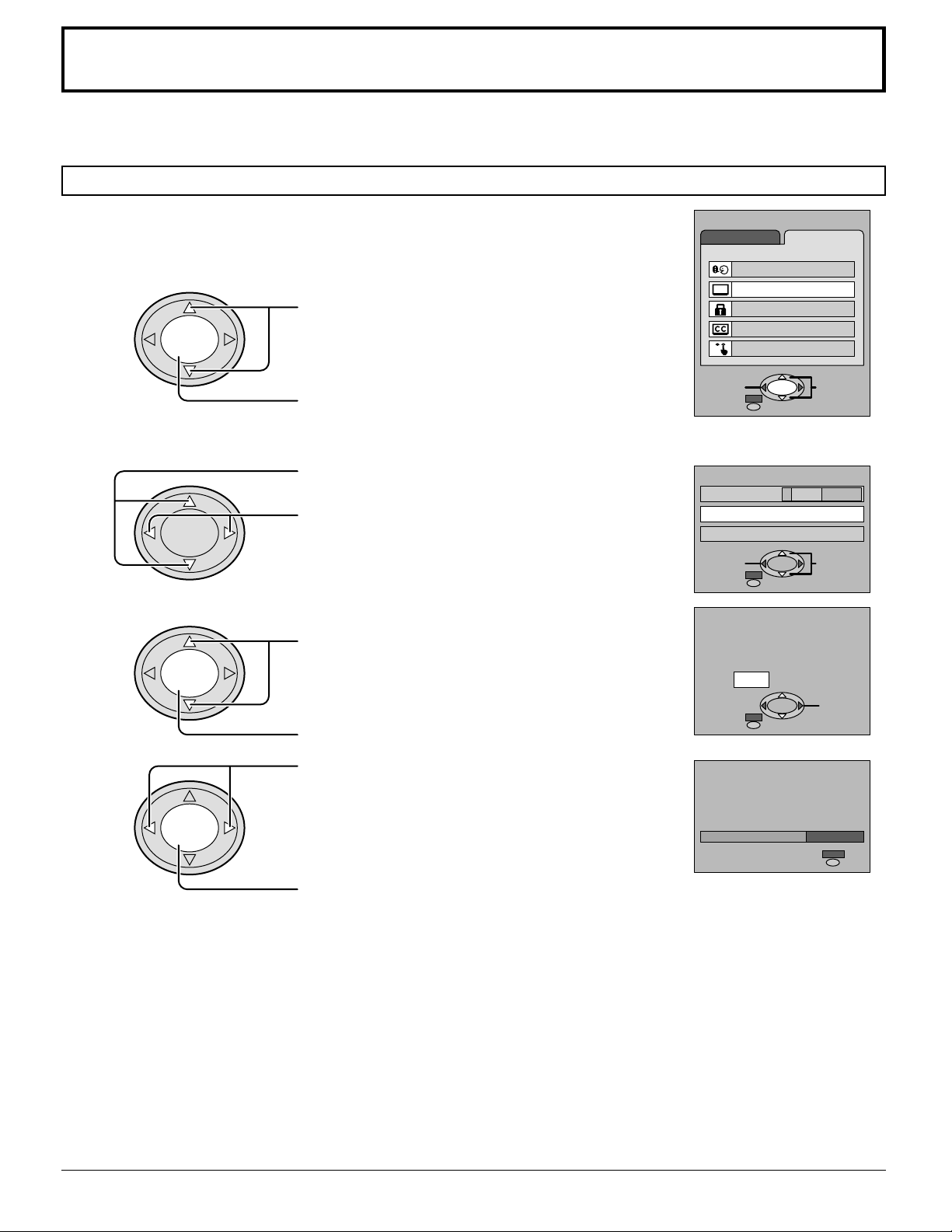
Tuning channels (Automatic channel programming)
Automatically searches and adds receivable channels in the installed area and / or CATV
signals to the program.
Channel tuning cannot be performed when the MAIN picture is not receiving a TV broadcast (tuning is not possible).
Press the MENU button to display the MENU screen and select SETUP.
1
2
CH
Press to select PROGRAM CHANNELS.
VOL VOL
ACTION
CH
CH
Press to display the PROGRAM CHANNELS.
Press to select MODE.
3
VOL VOL
ACTION
CH
CH
4
VOL VOL
ACTION
CH
Press to select TV or CABLE.
Press to select AUTO PROGRAM.
Press to display the confirmation screen.
MENU
ADJUST SET UP
LANGUAGE
PROGRAM CHANNELS
LOCK
CLOSED CAPTION
VIDEO
ACTION
EXIT
PROGRAM CHANNELS
MODE
AUTO PROGRAM
MANUAL PROGRAM
EXIT
AUTO PROGRAM
Activate
"AUTO PROGRAM"?
YES NO
EXIT
SELECTPAGE
TV CABLE
SELECTCHANGE
CHANNEL
CH
Press to select YES.
AUTO PROGRAM
5
IN "AUTO PROGRAM"
VOL VOL
ACTION
CH
Press to run AUTO PROGRAM.
CHANNEL
Channels will automatically advance until all channels have been scanned. Channel numbers with a video
signal present will turn blue which indicates stored in the Channel Scan Memory.
Press to select YES.
6
Notes:
When buttons are pressed with AUTO PROGRAM running, this unit will return to normal viewing. (Channels searched
•
up to this point are added.)
After AUTO PROGRAM is finished, the lowest channel number added will be received.
•
When there are no receivable channels, channel 69 is displayed (channel 125 for cable TV).
•
20
59
MENU
STOP
Page 21

Tuning channels (Manual channel programming)
Use this setting when changing setting of receiving channels or changing the channel display.
Turn this unit on and select the broadcast channel. Follow the steps on the previous page to display the
PROGRAM CHANNEL screen.
This PROGRAM CHANNEL screen can be displayed when the MAIN picture is a TV broadcast.
Press the MENU button to display the MENU screen and select SETUP.
1
2
VOL VOL
CH
ACTION
CH
CH
Press to select PROGRAM CHANNELS.
Press to display the PROGRAM CHANNELS.
Press to select MODE.
3
VOL VOL
ACTION
CH
CH
4
VOL VOL
ACTION
CH
Press to select TV or CABLE.
Press to select MANUAL PROGRAM.
Press to display the MANUAL PROGRAM screen.
MENU
ADJUST SET UP
LANGUAGE
PROGRAM CHANNELS
LOCK
CLOSED CAPTION
VIDEO
PROGRAM CHANNELS
EXIT
TV CABLE
122
ADD
CH SELECT
(or number key)
MODE
AUTO PROGRAM
MANUAL PROGRAM
MANUAL PROGRAM
ENTER CHANNEL:
DELETE
Adding or deleting channels
5
VOL VOL
6
VOL VOL
Repeat steps 4 and 5 to continue adding or deleting channels.
7
Press the MENU button to exit the set up menu.
8
CH
ACTION
CH
CH
ACTION
CH
Press to select channel ( or number keys ).
Press to add channels to memory ( blue ).
Press to select channel.
Press to delete channels from memory ( yellow ).
MANUAL PROGRAM
ENTER CHANNEL:
DELETE
EXIT
122
ADD
CH SELECT
(or number key)
21
Page 22

ASPECT Controls
The color monitor will allow you to enjoy viewing the picture at its maximum size, including wide screen cinema format
picture.
A
CBL
CH
CH
OFF TIMER
PLAY
SLOW
U
X
LIGHT
RCVR
INFO/RECALL
PC
GUIDE
FF
PAUSE
POWER
ASPECT
MUTE TV/VIDEO
DVD
VCR
DTV
V
T
VOL VOL
ACTION
MENU
NORMAL
SURROUND
VCR REC
EXIT
REW
STOP
VCR/DBS CHANNEL
TV/VCR
OPEN/CLOSE STILL
123
456
789
R-TUNE PROG
0
DBS
ASPECT
ASPECT button
The aspect mode changes each time the ASPECT button is
pressed.
Panasonic AUTO
NORMAL
JUST
ZOOM
FULL
When the ASPECT button is pressed, the screen mode switches to
Panasonic AUTO, regardless of the mode the screen is set to.
Notes:
(1) For a 480p signal input during component input signal mode, the mode
switches ZOOM and FULL only.
(2) When a 1080i and 720p signal is being received, the mode is set to
FULL, and aspect switching is not possible.
(3) During PC INPUT modes will change as follows:
NORMAL
FULL
(4) The aspect mode is memorized separately for each input terminal.
(TV, VIDEO1 – 3, COMPONENT1 – 2, PC)
22
Page 23

ASPECT Controls
Mode
Panasonic
AUTO
NORMAL
Picture
416
39
For an elongated image Image is expanded
4
3
For a 4:3 image
4
NORMAL
3
Panasonic AUTO
Changes in accordance
with the Panasonic
AUTO mode setting
(see page 49)
Explanation
The display will automatically become enlarged
(depending on the picture source), allowing you to view
the picture at its maximum size.
Notes:
(1) Panasonic AUT O mode is designed to automatically
adjust the aspect ratio to handle a mix of 16:9 and
4:3 program material. Certain 4:3 program material,
such as stock market data screens, may
occasionally cause the image size to change
unexpectedly. When viewing such programs, it is
recommended that the ASPECT be set to NORMAL.
(2) There may be a slight delay for the screen size to
adjust. If a 480p or 720p or 1080i signal is input
during component input signal mode, the controls
will not operate.
NORMAL will display a 4:3 picture at its standard 4:3
size.
JUST
ZOOM
FULL
4
3 9
16
JUST
JUST mode will display a 4:3 picture at its maximum
size but with aspect correction applied to the center of
the screen so that elongation is only apparent at the
left and right edges of the screen. The size of the picture
will depend on the original signal.
4
3
4
3
16
ZOOM
16
FULL
ZOOM mode magnifies the central section of the picture.
9
FULL will display the picture at its maximum size but
with sight elongation.
9
Note:
The screen size also changes if ID-1 is detected.
23
Page 24

VHF, UHF and CATV
R-STAND BY
POWER
G-
POWER
ON
Power switch
A
U
CBL
CH
CH
OFF TIMER
LIGHT
X
INFO/RECALL
PC
GUIDE
POWER
VCR
TV
VOL VOL
MENU
SURROUND
ASPECT
MUTE TV/VIDEO
DVD
DTV
ACTION
NORMAL
VCR REC
EXIT
RCVR
DBS
MENU
ACTION INPUT
1
POWER
2
3
VOL VOL
ACTION
VOLUME
TV
CH
CH
INPUT 3
VIDEO
L-AUDIO-R
CHANNEL
S-VIDEO
Operation can be done from this unit.
Channel buttons
•
Volume buttons
•
Press to turn this unit on (See page 15).
Press to operate this unit with the remote
control.
Press to select the desired channel.
REW
TV/VCR
OPEN/CLOSE STILL
123
456
789
R-TUNE PROG
24
PLAY
STOP
VCR/DBS CHANNEL
SLOW
0
FF
PAUSE
CH
Press to select the desired volume level.
4
VOL VOL
Notes:
The channel number and volume level are set even after this unit is turned
•
off.
Power consumption and howling of sound can be reduced if the volume
•
level is lowered.
ACTION
CH
Page 25

Cable TV
ANTENNA
TERMINALS ON THE
BACK OF THIS UNIT.
POWER
R-STAND BY
G-
POWER
ON
MENU
ACTION INPUT
VOLUME
CHANNEL
S-VIDEO
INPUT 3
VIDEO
L-AUDIO-R
When the antenna cable is connected to the TV antenna
terminal via a cable box or VCR, set the TV channel to
CH3 or CH4 (see page 9).
This does not apply when signal is input from VIDEO
INPUT.
POWER
MUTE TV/VIDEO
VCR
TV
ASPECT
DVD
DTV
CH
A
U
CBL
LIGHT
Confirming
Confirm that registration with cable TV and connection of equipment are
completed. Turn the cable TV tuner and select the desired volume level.
X
RCVR
DBS
ferrite sleeve
1
To antenna
Input
Incoming Cable from Antenna
or Cable TV System.
OUTPUT INPUT
CABLE BOX
CBL
VOL VOL
MENU
SURROUND
OPEN/CLOSE STILL
EXIT
REW
TV/VCR
ACTION
CH
OFF TIMER
NORMAL
VCR REC
PLAY
STOP
VCR/DBS CHANNEL
SLOW
INFO/RECALL
PC
GUIDE
FF
PAUSE
123
456
789
R-TUNE PROG
0
2
POWER
Press while pointing the remote control
towards the cable TV tuner.
Note:
The remote control code number is set for
Panasonic products.
When peripheral equipment do not
operate, reset code (See page 54).
Operate the cable TV tuner and select the desired volume level.
3
25
Page 26

Selection input signal
E
Confirming connection of the connector for desire selection signal.
TV
COMPONENT 2
ANT
DISPLAY OUT
CHANNEL
COMPONENT 1
AUDIO OUT
AUDIO R - L
COMPONENT
VIDEO INPUT
R
- PB - Y VIDEO
P
VIDEO 3
INPUT 3
S-VIDEO
VIDEO
L-AUDIO-R
-
IN
PC
1
2
1
2
AUDIO R
VIDEO
-
L
OUTPUT
INPUT
S-VIDEO
PC VIDEO 1
VIDEO 2
A video camera uses
the Video Input 3
terminal on the front
of this unit.
Video camera
Turning the power on and switching input modes
VCR
Laser Disk Player
DVD Player
This equipment can
also be connected to
the rear terminals. See
Connections for details.
POWER
VCR
TV
VOL VOL
MUTE
ASPECT
DVD
DTV
ACTION
LIGHT
TV/VIDEO
AU
X
RCVR
CBL
CH
DBS
Input modes can also be
switched using the INPUT button
on the unit.
MENU ACTION
INPUT
VOLUME
CHANNEL
1
2
POWER
TV/VIDEO
INPUT
Turn this unit on.
The input mode changes each time this
button is pressed.
TV
When playing
•
a video
When playing
•
a DVD
When playing from
•
a video camera
VIDEO 1
VIDEO 2
VIDEO 3
PC
COMPONENT 2
COMPONENT 1
No input mode is displayed for terminals with no equipment
connected (Excluding PC).
PC input can only be selected by using the INPUT button on the
front of the tuner.
PC input can also be selected by pressing the PC button on the remote.
Note:
When the remote control is unavailable, input modes can also be switched
on front of this unit using the INPUT button.
Operate the connected equipment.
3
26
Page 27

Recall
Recall (On-screen display)
TV, VIDEO input mode
A
U
CBL
CH
CH
OFF TIMER
PLAY
LIGHT
TV/VIDEO
X
INFO/RECALL
GUIDE
PAUSE
RCVR
PC
FF
POWER
MUTE
VCR
T
VOL VOL
MENU
SURROUND
TV/VCR
OPEN/CLOSE STILL
DVD
DTV
V
NORMAL
EXIT
REW
STOP
VCR/DBS CHANNEL
ASPECT
ACTION
VCR REC
SLOW
123
456
789
R-TUNE PROG
0
DBS
INFO/RECALL
The channel number remains, but other information
disappears after 10 seconds. Press this button again to
delete channel number display.
Full Information Channel number
CH123
STEREO
NORMAL
OFF TIMER 30
SAP
MONO
channel number or Video
Input Selected
multiplex sound
ASPECT mode
OFF TIMER status
(See page 45)
CH123
The INFO/RECALL button switches the display in the following order.
Full Information Channel No display
Press this button to display channel number, off-timer remaining time, screen
modes, and other settings.
PC input mode
INFO/RECALL
Press this button to display input signal, screen mode,
and disappears after 3 seconds.
Following screen is displayed in PC input mode.
PC
NORMAL
OFF TIMER 30
PC Input selected
ASPECT mode
OFF TIMER status
(See page 45)
27
Page 28

Adjusting screen POSITION/SIZE
POSITION / SIZE
POSITION
NORMAL
SIZE
NORMALIZE
1
(TV, VIDEO input mode)
Adjusting screen
1
2
VOL VOL
3
VOL VOL
ASPECT
MENU
CH
ACTION
CH
CH
ACTION
Press to select the screen mode to adjust.
Press to display the MENU.
Press to select
ADJUST menu.
MENU
ADJUST
PICTURE
PICTURE ADJUST
POSITION / SIZE
SOUND ADJUST
AUDIO MODE
EXIT
AUDIO
ACTION
SET UP
SELECTPAGE
Press to select
POSITION/SIZE.
A
CBL
CH
CH
OFF TIMER
PLAY
SLOW
0
U
X
LIGHT
RCVR
INFO/RECALL
PC
GUIDE
FF
PAUSE
POWER
ASPECT
MUTE TV/VIDEO
DVD
VCR
DTV
V
T
VOL VOL
ACTION
MENU
NORMAL
SURROUND
VCR REC
EXIT
REW
STOP
VCR/DBS CHANNEL
TV/VCR
OPEN/CLOSE STILL
123
456
789
R-TUNE PROG
DBS
Notes:
This unit is equipped with various screen modes. If a screen mode with a different aspect as the broadcast program is
•
selected, image will appear differently. Select the proper screen mode with this in mind.
Be careful when using this unit for commercial purposes or for public use, such as in cafes and hotels, for shrinking
•
and enlarging images by using screen mode switching function (zoom, etc.) may violate copyright laws.
Images displayed on a wide screen unit will be cut off or distorted at the edges, when viewing normal aspect images
•
of 4:3 in ZOOM, JUST or FULL mode. Display in NORMAL mode to view the original image intended by the producer.
For 1080i, 720p and 480p input images, screen position and size cannot be adjusted.
•
The adjusted setting will be kept even when this unit is turned off.
•
The signals output from the monitor output terminal on the back of this unit is not affected when the screen size and
•
position is adjusted.
28
CH
Press to display the
POSITION/SIZE screen.
Page 29

Adjusting screen POSITION/SIZE (TV, VIDEO input mode)
Switching screen width
During NORMAL mode, if noise appears on the ends of
the image in SIZE 1, switch to SIZE 2.
CH
VOL VOL
During JUST mode, if noise appears on the ends of the
image in SIZE 1, switch to SIZE 2.
VOL VOL
ACTION
CH
CH
ACTION
CH
Press to widen (SIZE 2).
Press to narrow (SIZE 1).
Press to enlarge image
horizontally (SIZE 2).
Press to shrink image
horizontally (SIZE 1).
Changing vertical size
During ZOOM modes.
CH
Press to enlarge image
vertically (max. 15).
(SIZE 1) (SIZE 2)
(SIZE 1) (SIZE 2)
To return to standard
•
To end adjustments
•
ACTION
MENU
(EXIT)
VOL VOL
ACTION
CH
Press to shrink image
vertically (min. 1).
To return to standard
•
To end adjustments
•
MENU
ACTION
(EXIT)
Displaying images cut off from the screen
For ZOOM and JUST modes.
CH
Press to move image
VOL VOL
Note:
If a “Cue” or “Rew” signal from a VCR or DVD player is received, the picture position will shift up or down. This picture
•
position movement cannot be controlled by the POSITION/SIZE function.
ACTION
CH
Helpful Hint (
upwards.
Press to move image
downwards.
NORMAL
/
ACTION
Normalization)
To end adjustments
•
MENU
When the NORMAL or ACTION button on the remote control is pressed when POSITION/SIZE is displayed, all settings
are returned to factory settings.
29
Page 30

Adjusting PICTURE POS./SIZE (PC input mode)
1
2
VOL VOL
3
VOL VOL
To end adjustments
•
MENU
CH
ACTION
CH
CH
ACTION
CH
Press to display PC MENU screen.
Press to select the
PICTURE POS./
SIZE.
Press to display
PICTURE POS./SIZE
menu screen.
Press to select the menu
to adjust each item.
Select the desired
level by best each
position/size.
MENU
PC MENU
PICTURE
PICTURE POS. / SIZE
SOUND
SIGNAL
EXIT
PICTURE POS./SIZE
NORMALIZE
NORMAL
H-POS
H-SIZE
V-POS
V-SIZE
CLOCK PHASE
EXIT
SELECT
SELECTADJUST
Press MENU button.
A
U
CBL
CH
CH
OFF TIMER
PLAY
LIGHT
X
INFO/RECALL
GUIDE
PAUSE
RCVR
PC
FF
POWER
ASPECT
MUTE TV/VIDEO
DVD
VCR
DTV
V
T
VOL VOL
ACTION
MENU
NORMAL
SURROUND
VCR REC
EXIT
REW
STOP
VCR/DBS CHANNEL
TV/VCR
OPEN/CLOSE STILL
SLOW
123
456
789
R-TUNE PROG
0
DBS
30
Page 31

Adjusting PICTURE POS./SIZE (PC input mode)
H-POS
H-SIZE
V-POS
When the Position Left
When the Position Left
When the Position Left
”
“
button is pressed
“
”
button is pressed
“ ”
button is pressed
When the Position Right
When the Position Right
When the Position Right
”
“
button is pressed
“
”
button is pressed
“ ”
button is pressed
“ ”
“ ”
button is pressed
or Right
“ ”
button to
When the Position Left
V-SIZE
CLOCK PHASE
Note:
Adjustment details of each input signal (frequency) for PC input signal modes are memorized separately.
Helpful Hint (
While the PICTURE POS./SIZE display is active, if either the NORMAL button on the remote control is pressed at any
time or ACTION button is pressed during “NORMALIZE”, then all adjustment values are returned to the factory settings.
Flickering and distortion can be eliminated by using the Position Left
carry out adjustment.
NORMAL
“ ”
NORMALIZE
/
button is pressed
Normalization)
When the Position Right
31
Page 32

Sound Adjustments
(TV, VIDEO input mode)
Press the MENU button to display the MENU screen and select ADJUST.
1
Select SOUND ADJUST of ADJUST from the MENU screen.
2
CH
VOL VOL
3
VOL VOL
ACTION
CH
CH
ACTION
CH
BASS
Adjusts low sounds
TREBLE
Adjusts high sounds
BALANCE
Adjust left and right volumes
SURROUND
To enjoy a concert hall effect, turn
SURROUND to ON.
During stereo sound or soft playing:
SURROUND
OFF ON
Press to select SOUND ADJUST
Press to SOUND ADJUST screen is displayed.
Press to select the menu to adjust each item.
Select the desired level by listening at the sound.
SOUND ADJ.
NORMALIZE
AUDIO MENU
BASS
TREBLE
BALANCE
SURROUND
EXIT
AUTO
0
0
0
OFF ON
SELECTADJUST
AUTO
STANDARD
MENU
ADJUST
PICTURE ADJUST
POSITION / SIZE
SOUND ADJUST
AUDIO MODE
EXIT
PICTURE
AUDIO
ACTION
SET UP
SELECTPAGE
Automatically
controls volume level.
Emits the original
sound.
During monaural sound:
SURROUND
OFF ON
To reset to standard setting
CH
VOL VOL
•
ACTION
CH
To end adjustments
32
Select NORMALIZE with the up
NORMAL
(NORMAL button).
MENU
and down
Press MENU button.
buttons and press ACTION button or
Page 33

Sound
SOUND
NORMALIZE
AUDIO MENU
BASS
TREBLE
STANDARD
ON
0
0
0
BALACE
SURROUND
NORMAL
SELECTADJUST
EXIT
Adjustments (PC input mode)
Press the MENU button to display the PC MENU screen.
1
2
VOL VOL
Select of adjust each item.
3
VOL VOL
BASS
Adjusts low sounds
TREBLE
Adjusts high sounds
BALANCE
Adjust left and right volumes
SURROUND (see page 37)
Selection ON or OFF
To end adjustments
•
CH
ACTION
CH
CH
ACTION
CH
Press to select SOUND.
Press to display SOUND menu screen,
Press to select the menu to adjust.
Select the desired level by listening to the sound.
SOUND
NORMALIZE
AUDIO MENU
BASS
TREBLE
BALACE
SURROUND
MENU
NORMAL
AUTO
0
0
0
ON
EXIT
Press MENU button.
SELECTADJUST
AUTO
STANDARD
PC MENU
PICTURE
PICTURE POS. / SIZE
SOUND
SIGNAL
EXIT
Automatically
controls volume level.
Emits the original
sound.
SELECT
Note:
Press the SURROUND button to directly turn the surround effect ON and OFF. (see page 37)
NORMAL
Helpful Hint (
While the “SOUND” menu is displayed, if either the NORMAL button on the remote control is pressed at any time or the
ACTION button is pressed during “NORMALIZE”, then all adjustment values are returned to the factory settings.
NORMALIZE
/
Normalization)
Mute
Useful when answering the phone or receiving unexpected visitors.
MUTE
Press this button to mute the sound.
Press again to reactivate sound. Sound is also reactivated when power is turned off
or volume level is changed.
33
Page 34

Picture Adjustments
(for TV, VIDEO input mode)
Press the MENU button to display the MENU screen and select ADJUST.
1
CH
Press to select PICTURE ADJUST.
VOL VOL
ACTION
CH
Press to display the PICTURE ADJUST screen.
NORMAL is displayed at default.
2
CH
Press to select the menu to adjust each item.
Select the desired level by looking at the picture
VOL VOL
ACTION
CH
behind the menu.
MENU
ADJUST
PICTURE
PICTURE ADJUST
POSITION / SIZE
AUDIO
SOUND ADJUST
AUDIO MODE
ACTION
EXIT
PICTURE ADJ.
PICTURE MENU
PICTURE
BRIGHTNESS
COLOR
TINT
SHARPNESS
COLOR TEMP
EXIT
SET UP
SELECTPAGE
NORMALIZE
STANDARD
0
0
0
0
0
COOL
SELECTADJUST
PICTURE ADJ.
PICTURE MENU
PICTURE
BRIGHTNESS
COLOR
TINT
SHARPNESS
COLOR TEMP
EXIT
see next page
NORMALIZE
STANDARD
0
0
0
0
0
COOL
SELECTADJUST
Press the left
STANDARD CINEMA DYNAMIC
STANDARD
CINEMA
DYNAMIC
Press the left
or right
button to switch between modes.
STANDARD
Displays unaltered image.
CINEMA
Ideal for movies.
DYNAMIC
Displays a clear screen with contrast of light
and dark.
or right
button to switch between modes.
NORMAL COOL WARM
34
Page 35

Picture Adjustments (for TV, VIDEO input mode)
PICTURE
Selects proper brightness and density for the
room.
PICTURE ADJ.
NORMALIZE
BRIGHTNESS
Adjusts for easier viewing of dark pictures
such as night scenes and hair.
COLOR
Adjusts slightly to a lighter color.
TINT
Adjust for nice skin color.
SHARPNESS
Displays a sharp image.
COLOR TEMP (Color Temperature)
classifying white light.
To adjust each item,
•
VOL VOL
CH
ACTION
PICTURE MENU
PICTURE
BRIGHTNESS
COLOR
TINT
SHARPNESS
COLOR TEMP
EXIT
Press the up
adjustments using the left
and down button and make
STANDARD
0
0
0
0
0
COOL
SELECTADJUST
and right buttons.
CH
To reset to standard setting,
•
To end adjustments.
•
Helpful Hint (
While the “PICTURE” menu is displayed, if either the NORMAL button on the remote control is pressed at any time or
the ACTION button is pressed during “NORMALIZE”, then all adjustment values are returned to the factory settings.
CH
VOL VOL
NORMAL
ACTION
CH
MENU
NORMALIZE
/
Select NORMALIZE with the up
buttons.
Press ACTION.
Press MENU button.
Normalization)
and down
Note:
There is little change when PICTURE is increased with a bright picture or reduced with a dark picture.
35
Page 36

Picture Adjustments (PC input mode)
PICTURE
NORMALIZE
PICTURE MENU
BRIGHTNESS
STANDARD
0
COLOR TEMP
NORMAL
PICTURE
0
NORMAL
SELECTADJUST
EXIT
Press the MENU button to display the MENU screen and select ADJUST.
1
CH
Press to select to PICTURE.
VOL VOL
ACTION
CH
Press to display the PICTURE screen.
NORMAL is displayed at default.
2
CH
Press to select the menu to adjust.
Select the desired level by looking at the picture
VOL VOL
PICTURE
NORMALIZE
PICTURE MENU
PICTURE
BRIGHTNESS
COLOR TEMP
ACTION
NORMAL
EXIT
CH
STANDARD
0
0
NORMAL
SELECTADJUST
behind the menu.
Press the left
STANDARD
or right
STANDARD
Displays unaltered image.
PC MENU
PICTURE POS. / SIZE
EXIT
button to switch between modes.
STANDARD DYNAMIC
PICTURE
SOUND
SIGNAL
SELECT
DYNAMIC
DYNAMIC
Displays a clear screen with contrast of light and
dark.
MENU
Item
Press MENU button.
Effect
Less More
Darker Brighter
NORMAL
NORMALIZE
/
Press the left
or right
button to switch between modes.
NORMAL COOL WARM
Adjustment
Selects the proper brightness and density for the room.
Adjusts for easier viewing of dark pictures such as
night scenes an black hair.
Normalization)
To end adjustments.
•
PICTURE
BRIGHTNESS
Helpful Hint (
While the “PICTURE” menu is displayed, if either the NORMAL button on the remote control is pressed at any time or
the ACTION button is pressed during “NORMALIZE”, then all adjustment values are returned to the factory settings.
36
Page 37

SURROUND Controls
A
U
CBL
CH
CH
OFF TIMER
PLAY
LIGHT
TV/VIDEO
X
INFO/RECALL
GUIDE
PAUSE
RCVR
PC
FF
POWER
MUTE
VCR
T
VOL VOL
MENU
SURROUND
TV/VCR
OPEN/CLOSE STILL
DVD
DTV
V
NORMAL
EXIT
REW
STOP
VCR/DBS CHANNEL
ASPECT
ACTION
VCR REC
SLOW
123
456
789
R-TUNE PROG
0
DBS
SURROUND
SURROUND Button
The benefits of surround sound are enormous. You can
be completely enveloped in sound, just as if you were at
a concert hall or cinema.
The surround setting switches on and off each time the
SURROUND button is pressed.
ON
OFF
TV, VIDEO INPUT MODE
SURROUND
ON
PC INPUT MODE
SURROUND
ON
Note:
The surround settings are memorized separately for each SOUND mode
(AUTO, STANDARD).
37
Page 38

Closed Captions
This unit has a built in decoder that provides a visual depiction of the audio portion of a
television program in the form of written words across the screen (white or colored letters
on a black background). It allows the viewer to read the dialogue of a television program or
other information.
Press the MENU button to display the MENU screen and select SETUP.
1
(Except in PC input mode)
CH
Press to select CLOSED CAPTION.
VOL VOL
CC ON MUTE
2
ACTION
CH
Press to display the CLOSED CAPTION screen.
Activates the On-Screen Closed Caption feature, when the MUTE button on
the Remote Control is pressed. To deactivate, press the MUTE button again.
Note:
This feature functions when the Closed Caption Mode is in the “OFF” position.
The program being viewed must be broadcast with Closed Caption.
CH
Press to select ON MUTE.
Press to select from the following:
VOL VOL
ACTION
MENU
ADJUST SET UP
LANGUAGE
PROGRAM CHANNELS
LOCK
CLOSED CAPTION
VIDEO
ACTION
EXIT
CLOSED CAPTION
ON MUTE
MODE
EXIT
ON MUTE
SELECTPAGE
C3
T1
SELECTCHANGE
C3
NO(OFF) C1 C2 C3 C4
CH
Notes:
Recommended menu Set Up for Closed Caption when using Mute Button.
•
CC ON MUTE: C1
CC MODE : OFF
The setting for CC ON MUTE is valid only when the CC MODE is OFF, CC MODE set to ON will override CC ON
•
MUTE.
This menu cannot be selected when the picture is displaying a COMPONENT VIDEO INPUT of 480i or more.
When aspect is ZOOM, Closed Caption cannot be used.
•
38
Page 39

Closed Captions
CC MODE
3
Activates the On-Screen Closed Caption feature. When activated this feature
will remain on until OFF is selected in this menu.
CH
VOL VOL
ACTION
CH
CAPTION OFF -
•
CAPTION C1 -
•
CAPTION C2 -
•
TEXT T1 -
•
TEXT T2 -
•
CAPTION C3 -
•
CAPTION C4 -
•
TEXT T3 -
•
TEXT T4 -
•
Recommended mode when Closed Caption is not being used.
For video related information that can be displayed (up to 4 lines of script strategically
placed on the television screen so that it does not obstruct relevant parts of the picture).
Another mode used for video related information.
Blanks out a large portion of the picture on the television screen, and displays program
guide or any other information currently being transmitted.
Another mode which displays information and blanks out a large portion of the picture on
the television screen.
Another mode used for video related information.
Another mode used for video related information.
Another mode which displays information and blanks out a large portion of the picture on
the television screen.
Another mode which displays information and blanks out a large portion of the picture on
the television screen.
Press to select CC MODE.
Press to select from the following:
OFF C1 C2 T1 T2
T4 T3 C4 C3
CLOSED CAPTION
ON MUTE
MODE
EXIT
C3
T1
SELECTCHANGE
To end adjustments
•
MENU
Press MENU button.
39
Page 40

Lock Feature
In the United States, the V-CHIP consists of two rating systems, which are MPAA (MOTION
PICTURE) and TV PARENTAL GUIDELINES. Its function is to block programs by the rating
data in the XDS data packets sent from broadcasting stations. The user can select which
rating programs should be blocked by the LOCK MENU options.
Note: The V-CHIP. used in this unit model, is capable of selecting the U.S. ratings that are
indicated in this manual.
Press the MENU button to display the MENU screen and select SETUP.
(Except in PC input mode)
AU
CBL
CH
CH
OFF TIMER
PLAY
0
LIGHT
X
INFO/RECALL
PC
GUIDE
FF
PAUSE
POWER
MUTE TV/VIDEO
VCR
T
VOL VOL
MENU
SURROUND
TV/VCR
OPEN/CLOSE STILL
ASPECT
DVD
DTV
V
ACTION
NORMAL
VCR REC
EXIT
REW
STOP
VCR/DBS CHANNEL
SLOW
123
456
789
R-TUNE PROG
RCVR
DBS
1
CH
MENU
ADJUST SET UP
Press to
VOL VOL
ACTION
CH
select LOCK.
Press to
LANGUAGE
PROGRAM CHANNELS
LOCK
CLOSED CAPTION
VIDEO
display the
LOCK screen.
EXIT
Input code
Enter any 4-digit number as a password.
LOCK
MOTION PICT. STATUS
These numbers will be needed when
deactivating the LOCK function.
ENTER CODE FIRST
CHANGE SETTING
TV PARENTAL STATUS
CHANGE SETTING
ENTER CODE FIRST
EXIT
Note:
Use a code that is easy to remember or record it in a safe place.
ACTION
SELECTPAGE
OFF ON
OFF ON
RETRY
40
Selecting broadcasts to lock.
2
CH
Press to select CHANGE SETTING (the
VOL VOL
ACTION
CH
menu following MOTION PICT. STATUS).
Press to display the MOTION PICTURE
RATING screen.
LOCK
MOTION PICT. STATUS
OFF ON
CHANGE SETTING
TV PARENTAL STATUS
OFF ON
CHANGE SETTING
CHANGE CODE
EXIT
SELECTCHANGE
Page 41

Lock Feature
3
CH
Press to select rating to lock.
VOL VOL
ACTION
CH
CH
Press to select YES or NO.
Rating (turns red when on)
VOL VOL
ACTION
G : General audience
PG : Parental guidance suggested
PG-13: Parental guidance needed under 13 years old
CH
R : Restricted
NC17 : No one under 17 is admitted
X : Pornography
EXIT
Press to return to LOCK screen.
Setting MOTION PICT. STATUS.
4
Locking and unlocking the ratings selected above.
CH
Press to select MOTION PICT. STATUS.
Press to select ON or OFF.
VOL VOL
ACTION
MOTION PICTURE RATING
VIEW NR PROGRAMS?
LOCK
MOTION PICT. STATUS
TV PARENTAL STATUS
CHANGE CODE
NO YES
G
PG
PG–13
R
NC–17
X
EXIT
CHANGE SETTING
CHANGE SETTING
SELECTCHANGE
OFF ON
OFF ON
CH
ON : The broadcasts selected in the MOTION PICTURE RATING menu cannot
be viewing.
OFF: LOCK is deactivated and any broadcast, regardless of the setting for
MOTION PICTURE RATING, can be viewing.
EXIT
MOTION PICT. STATUS
SELECTCHANGE
OFF ON
41
Page 42

Lock Feature
TV PARENTAL STATUS
CH
VOL VOL
VOL VOL
Setting the TV PARENTAL PROGRAMS screen
ACTION
CH
CH
ACTION
CH
VIEW NR PROGRAMS?
NO : Cannot view programs with NR signals.
YES : Can view programs with NR signal.
SETTING
BASIC : The up
DETAILED : The cursor selecting the title can be moved to select options displayed on the right.
LOCK
Press to select TV PARENTAL STATUS.
Press to select ON or OFF.
Changing setting
Press to select CHANGING SETTING
(the menu following TV PARENTAL STATUS).
Press to display the TV PARENTAL GUIDE screen.
The down
and down
buttons change the selected title.
buttons moves the cursor to the right if options are available. The up
MOTION PICT. STATUS
TV PARENTAL STATUS
CHANGE CODE
TV PARENTAL GUIDE
VIEW NR PROGRAMS?
SETTING DETAILED
TV—Y
TV—Y7
TV—G
TV—PG
TV—14
TV—MA
OFF ON
CHANGE SETTING
OFF ON
CHANGE SETTING
EXIT
EXIT
SELECTCHANGE
NO YES
FV
V
S
V
L
S
V
L
S
SELECTCHANGE
DDL
buttons moves the cursor to the left and if there are no options to the left, the cursor
will move up.
Locking and unlocking
When a title field is selected, all ratings below this rating are selected.
•
When options within an option field are selected, ratings below this rating within the same field are
•
selected.
Ratings displayed in green are unlocked and those displayed in red are blocked programs.
•
1. Ratings for children: These ratings are divided into ranks as follows.
TV-Y
TV-YTV-Y7 TV-Y7 TV-Y7-FVFV
2. Ratings for teenagers: These ratings are the same as the matrix system. This system is described in the
below diagram. Ratings for all ages are on top and ratings for adults are on the bottom.
TV-G
TV-PG
TV-14
TV-MA
To end adjustments
•
V
V
V
V
S
L
D
S
L
D
S
L
D
S
L
MENU
Press MENU button.
42
Page 43

Customizing the VIDEO INPUT labels
Display for each VIDEO INPUT can be changed to match with the connected device (VCR,
DVD Player).
Example: When changing VIDEO 3 to LD.
Press the MENU button to display the MENU screen and select SETUP.
1
(Except in PC input mode)
CH
Press to select VIDEO.
VOL VOL
2
ACTION
CH
CH
Press to display the VIDEO screen.
Press to display P AGE 3/3 and select VIDEO
INPUT LABEL.
VOL VOL
ACTION
MENU
ADJUST SET UP
LANGUAGE
PROGRAM CHANNELS
LOCK
CLOSED CAPTION
VIDEO
ACTION
EXIT
VIDEO
NATURAL COLOR
VIDEO NR
DVC PLAYBACK MODE
VIDEO
VIDEO INPUT LABEL
480p COLOR MATRIX
NORMAL FRAME
EXIT
SELECTPAGE
PAGE 1/3
OFF ON
OFF ON
SELECTCHANGE
PAGE 3/3
SDTV HDTV
CH
Press to display the VIDEO INPUT LABEL screen.
Note:
The VIDEO screen consists of 3 pages.
Use the up
and down buttons to change pages.
EXIT
SELECTCHANGE
43
Page 44

Customizing the VIDEO INPUT labels
O
3
VOL VOL
VOL VOL
CH
ACTION
CH
CH
ACTION
CH
CH
TION
CH
VOL
Press to select VIDEO INPUT to change.
Press to change.
By pressing this button, display changes as follows:
VIDEO 2 VCR LD
BLANK HD VCR DTV DVD
VIDEO INPUT LABEL
VIDEO1
VIDEO2
VIDEO3
COMPONENT1
COMPONENT2
COMPONENT1
COMPONENT2
EXIT
VIDEO1
VIDEO2
VIDEO3
SELECTCHANGE
VOL
ACTI
MENU
CH
This button rotates in reverse.
CH
Press to end.
Note:
When DVD or DTV is selected for the change, images are adjusted to match each input signal.
44
Page 45

Selecting STEREO / SAP / MONO
Press the MENU button to display the MENU screen and select ADJUST.
(Except in PC input mode)
CH
Press to select AUDIO MODE.
VOL VOL
ACTION
CH
CH
Press to display the AUDIO MODE screen.
Press to select STEREO / SAP / MONO.
Red display : With signal
VOL VOL
ACTION
White display : No signal
: MONO
CH
MENU
Press to end.
MENU
ADJUST
PICTURE
PICTURE ADJUST
POSITION / SIZE
AUDIO
SOUND ADJUST
AUDIO MODE
ACTION
EXIT
AUDIO MODE
AUDIO MODE
STEREO
EXIT
SAP
SET UP
SELECTPAGE
MONO
CHANGE
Helpful Hints:
STEREO - Two channel Audio reception.
•
SAP - Second Audio Programming (typically
•
used for bilingual audio).
MONO - Use when stereo signal is weak.
•
Using the OFF-TIMER
1
OFF TIMER
Press the OFF TIMER button to
display the OFF TIMER screen.
The Wide Plasma Display may be preset to switch to standby after a fixed period. The setting changes to 30 minutes,
60 minutes, 90 minutes and 0 minutes (off timer cancelled)
each time the button is pressed.
30 60
90
0
When three minutes remain, “Off timer 3” will flash. The off timer is cancelled if the main supply fails.
OFF TIMER 90
Notes:
When power to this unit set is disrupted due to a power outage or similar problem, after power is restored, the off-
•
timer will be deactivated and this unit will be in standby mode.
To see the remaining sleep time, press the INFO/RECALL button.
•
45
Page 46

Optimizing display for DVC recording mode (DVC PLAYBACK MODE)
When digital video camera recording is in FRAME, images will have high resolution.
Press the MENU button to display the MENU screen and select SETUP.
1
(Except in PC input mode)
CH
Press to select VIDEO.
VOL VOL
ACTION
CH
CH
Press to display the VIDEO screen.
Press to select DVC PLAYBACK MODE.
VOL VOL
2
VOL VOL
ACTION
CH
CH
ACTION
Press to set.
NORMAL :When playing normal images.
FRAME :When displaying FRAME
recording mode.
CH
MENU
ADJUST SET UP
LANGUAGE
PROGRAM CHANNELS
LOCK
CLOSED CAPTION
VIDEO
ACTION
EXIT
VIDEO
NATURAL COLOR
VIDEO NR
DVC PLAYBACK MODE
DVC PLAYBACK MODE
NORMAL FRAME
EXIT
NORMAL FRAME
SELECTPAGE
PAGE 1/3
OFF ON
OFF ON
SELECTCHANGE
MENU
Press to end.
Notes:
Switches only during VIDEO INPUT 1-3 modes.
•
If normal images are viewed in FRAME mode, moving pictures may appear awkward. Switch to NORMAL.
•
The VIDEO screen consists of 3 pages.
•
Use the up
•
and down
buttons to change pages.
46
Page 47

Adjusting unnatural video images (3D Y/C FIL TER)
Selecting the VIDEO menu
Press the MENU button to display the MENU screen and select SETUP.
(Except in PC input mode)
CH
Press to select VIDEO.
VOL VOL
ACTION
CH
Press to display the VIDEO screen.
Switching to 3D Y/C FILTER
MENU
ADJUST SET UP
LANGUAGE
PROGRAM CHANNELS
LOCK
CLOSED CAPTION
VIDEO
ACTION
EXIT
VIDEO
NATURAL COLOR
VIDEO NR
DVC PLAYBACK MODE
NORMAL FRAME
EXIT
SELECTPAGE
PAGE 1/3
OFF ON
OFF ON
SELECTCHANGE
1
VOL VOL
2
VOL VOL
CH
ACTION
CH
CH
ACTION
CH
MENU
Press to select 3D Y/C FILTER.
Press to turn OFF.
Press to end.
VIDEO
3D Y / C FILTER
ID - 1
Panasonic AUTO 4 : 3
OFF ON
OFF ON
JUST NORMAL
EXIT
PAGE 2/3
SELECTCHANGE
Notes:
The VIDEO menu is made up of 3 pages.
•
Use the up
Not available for COMPONENT VIDEO 1 – 2.
•
and down
buttons to change pages.
47
Page 48

Automatically changing screen size for VIDEO INPUT modes
If the received signal contains screen size specifications in VIDEO INPUT (1 – 3) or
COMPONENT VIDEO INPUT (1 – 2), the screen size is automatically changed.
Press the MENU button to display the MENU screen and select SETUP.
1
(Except in PC input mode)
CH
Press to select VIDEO.
VOL VOL
ACTION
CH
CH
Press to display the VIDEO screen.
Press to display P AGE 2/3 and select ID-1
VOL VOL
2
ACTION
CH
CH
(Image Detection).
Press to set.
ON : When screen size specification signals
VOL VOL
ACTION
are detected, screen size is
automatically changed.
OFF : The screen size is not automatically
CH
changed. (Turn OFF if this function
does not operate properly.)
MENU
ADJUST SET UP
LANGUAGE
PROGRAM CHANNELS
LOCK
CLOSED CAPTION
VIDEO
ACTION
EXIT
VIDEO
NATURAL COLOR
VIDEO NR
DVC PLAYBACK MODE
VIDEO
3D Y / C FILTER
ID - 1
Panasonic AUTO 4 : 3
NORMAL FRAME
EXIT
JUST NORMAL
EXIT
SELECTPAGE
PAGE 1/3
OFF ON
OFF ON
SELECTCHANGE
PAGE 2/3
OFF ON
OFF ON
SELECTCHANGE
MENU
Press to end.
Note:
When ID-1 is detected and screen size is changed, FULL or WIDE will be display.
Use the up
and down
buttons to change pages.
48
ID - 1
OFF ON
Page 49

Cancelling automatic enlarging of screen
Used for viewing 4:3 images in Panasonic auto mode. (See page 23)
Press the MENU button to display the MENU screen and select SETUP.
1
(Except in PC input mode)
CH
Press to select VIDEO.
VOL VOL
2
ACTION
CH
CH
Press to display the VIDEO screen.
Press to display PAGE 2/3 and select Panasonic
AUTO.
Press to select NORMAL.
VOL VOL
ACTION
CH
MENU
ADJUST SET UP
LANGUAGE
PROGRAM CHANNELS
LOCK
CLOSED CAPTION
VIDEO
ACTION
EXIT
VIDEO
NATURAL COLOR
VIDEO NR
DVC PLAYBACK MODE
VIDEO
3D Y / C FILTER
ID - 1
Panasonic AUTO 4 : 3
NORMAL FRAME
EXIT
JUST NORMAL
SELECTPAGE
PAGE 1/3
OFF ON
OFF ON
SELECTCHANGE
PAGE 2/3
OFF ON
OFF ON
Panasonic AUTO 4 : 3
JUST NORMAL
MENU
Displays NORMAL screen for 4:3 images.
Displays JUST screen for 4:3 images.
Press to end.
Note:
The VIDEO screen consists of 3 pages.
Use the up
and down
buttons to change pages.
EXIT
SELECTCHANGE
49
Page 50

Setting when 480p signals (sequential scan) are input through COMPONENT VIDEO INPUT
Displays input signals (480p signals) in a natural color from digital equipment adapters
connected to COMPONENT VIDEO INPUT (Y, Pb / Cb ,Pr / Cr input terminals).
Press the MENU button to display the MENU screen and select SETUP.
1
(Except in PC input mode)
CH
Press to select VIDEO.
VOL VOL
ACTION
CH
CH
Press to display the VIDEO screen.
Press to display PAGE 3/3 and select 480p COLOR
VOL VOL
2
ACTION
CH
CH
MA TRIX.
Press to set.
SDTV : When the input signal is a normal TV
VOL VOL
ACTION
system (NTSC).
HDTV : When the input signal is a Hi-Definition
system (HD).
CH
MENU
ADJUST SET UP
LANGUAGE
PROGRAM CHANNELS
LOCK
CLOSED CAPTION
VIDEO
ACTION
EXIT
VIDEO
NATURAL COLOR
VIDEO NR
DVC PLAYBACK MODE
VIDEO
VIDEO INPUT LABEL
480p COLOR MATRIX
NORMAL FRAME
EXIT
SELECTPAGE
PAGE 1/3
OFF ON
OFF ON
SELECTCHANGE
PAGE 3/3
SDTV HDTV
EXIT
MENU
Press to end.
Note:
The VIDEO screen consists of 3 pages.
Use the up
and down
buttons to change pages.
480p COLOR MATRIX does not need to be set when using Hi-Definition equipment or 480i output equipment.
SELECTCHANGE
50
Page 51

Switching languages for display
Press the MENU button to display the MENU screen and select SETUP.
1
(Except in PC input mode)
CH
Press to select LANGUAGE.
VOL VOL
2
VOL VOL
ACTION
CH
CH
ACTION
CH
MENU
Press to display the LANGUAGE screen.
Press to select preferred language.
Press to end.
MENU
ADJUST SET UP
LANGUAGE
PROGRAM CHANNELS
LOCK
CLOSED CAPTION
VIDEO
ACTION
EXIT
LANGUAGE
LANGUAGE
ENGLISH Français
EXIT
SELECTPAGE
CHANGE
51
Page 52

SET UP for PC Input Signals
Press the MENU button to display the PC MENU screen, and select PC
MENU.
CH
Press to select each item.
Press to adjust.
VOL VOL
ACTION
CH
MENU
Press to end.
SYNC
Setting PC sync signal setting:
Confirm that the input is set to PC INPUT (this setting is valid only for PC
INPUT).
H&V: The H and V sync signals are input from the HD / VD connector.
ON G: Uses a synchronized signal on the Video G signal, which is input
from the G connector.
SIGNAL
SYNC
PULL-IN RANGE
CLAMP POSITION
H
-
FREQ. kHz
-
FREQ. Hz
V
EXIT
SYNC
SYNC
H & V
NARROW
31.5
60.0
SELECTCHANGE
H & V
ON G
PULL IN RANGE
Sets the width for different frequencies.
CLAMP POSITION
Adjusts the clamp position.
The following operation methods are the same for “SIGNAL” menu.
Normally, these adjustments are set to appropriate levels and therefore do
not need to be altered.
H-FREQ (kHz) / V-FREQ (Hz)
Displays the H (horizontal) / V ( vertical) frequencies.
Display range:
Horizontal 15.5 – 110 kHz
Vertical 48 – 120 Hz
PULL-IN RANGE
PULL-IN RANGE
CLAMP POSITION
H-FREQ. kHz
V
-
FREQ. Hz
NARROW
WIDE
31.5
60.0
52
Page 53

Operating peripheral equipment using the remote control
Programming The Illuminated Remote Control Using Access Codes
The remote control can be preset for other manufactures, by utilizing the REMOTE MODE SELECTION BUTTONS
for CABLE, DTV, VCR, RCVR (a Receiver or Amplifier), DVD (DVD, CD, LD) ,DBS and AUX (for Cassette Player
or a VCR2.)
(Details on remote control buttons to operate peripheral equipment
1. Setting up the remote using the numerical keys. (When code known):
See page 55 to 57 and 58 to 60)
1
2
3
POWER
+
CH
VOL VOL
VCR
TV
ACTION
CH
DVD
DTV
123
456
789
AUX
CBL
RCVR
D
B
S
Press and hold the POWER and ACTION keys simultaneously for three full
seconds.
After 3 seconds, all the illuminated mode keys will begin to flash. Then let go of the
POWER and ACTION keys.
Press the desired mode key.
The mode key will illuminate steadily , all others will go out.
Enter the three digit set up code, by using the Remote Control Keyboard.
If the correct code is entered, the mode key will blink twice and then go out.
Now your remote is set for this code.
0
Note:
If an incorrect number is entered (or there is an incomplete entry after 28 seconds), the key illumination goes out (no
blink) and setting are unchanged.
Device
TV
VCR
CBL
DBS
RCVR
AUX
DVD
DTV
TV (Only Panasonic)
VCR (Preset)
Cable Boxes (Preset)
DBS Boxes (Preset)
RCVR (Preset)
Cassette Players, VCR2 (Preset)
DVD & LD & CD Player (Preset)
STB (Only Panasonic)
Operate
Default
Panasonic Code
Panasonic Code
Panasonic Code
Panasonic Code
Technics Code
Technics Cassette Players Code
Panasonic DVD Code
Panasonic Code
53
Page 54

Operating peripheral equipment using the remote control
2.
Setting to the remote using the step and set method
(When code not known):
AU
CBL
CH
CH
OFF TIMER
PLAY
0
LIGHT
X
INFO/RECALL
GUIDE
PAUSE
RCVR
PC
FF
POWER
ASPECT
MUTE TV/VIDEO
DVD
VCR
DTV
TV
ACTION
VOL VOL
MENU
NORMAL
SURROUND
VCR REC
EXIT
REW
STOP
VCR/DBS CHANNEL
TV/VCR
OPEN/CLOSE STILL
R-TUNE PROG
SLOW
123
456
789
DBS
1
2
3
4
POWER
+
CH
VOL VOL
VCR
TV
VOL VOL
ACTION
DVD
DTV
ACTION
CH
AUX
CBL
CH
CH
CH
RCVR
DBS
Press and hold the POWER and ACTION
keys simultaneously for three full
seconds.
After 3 seconds, all the illuminated mode
keys will begin to flash. Then let go of the
POWER and ACTION key.
Press the mode key.
The mode key will illuminate steadily , all
others will go out.
Press VOL “
” key to step to the next code.
Press POWER to send a test signal in
that format.
Continue doing this until the proper
device code is found, And the target
device responds.
Once the code has been found, press the
ACTION key to lock it in.
VOL VOL
ACTION
CH
Notes:
The step and set mode will start from the current device (not the beginning
•
of the library, except for the first time).
The step and set mode works in the reverse direction using the VOL “
•
Infrared Remote Codes for Specific Components
Helpful Hint: Write down the code numbers for your components in the space provided below. This will serve as a
handy reference whenever you need to reprogram your remote control.
CABLE
Cable Box
DBS
Digital Broadcast System
Other Component
Other Component
VCR
Video Cassette Recorder
RCVR
Receiver or Amplifier
Other Component
Other Component
CD
Compact Disc Player
LD
Laser Disc Player
Other Component
Other Component
54
” key.
Page 55

Operating peripheral equipment using the remote control
Infrared Codes Index
The remote control is capable of operating many brands of peripheral equipment. Refer to page 56 and 57 for
programming procedures.
Note: The remote control memory is limited and therefore some models may not operate. The remote control is not
designed to control all features available in all models.
Note: After entering the proper infrared code, press the desired Mode Selection Button on the remote control. Refer
to page 16 and 58 to 60 for details on operating peripheral equipment using the remote control.
VCR Infrared Codes Index
VCR
VCR
Maker
ADMIRAL
AIWA
AKAI
AUDIO DYNAMIC
BELL & HOWELL
BROKSONIC
CANON
CITIZEN
CRAIG
CURTIS MATHES
DAEWOO
DBX
DIMENSIA
EMERSON
FISHER
FUNAI
GE
GO VIDEO
GOLDSTAR
HITACHI
INSTANT REPLAY
JENSEN
JVC
KENWOOD
LXI
MAGNAVOX
MARANTZ
MARTA
MEMOREX
MGA
MINOLTA
MITSUBISHI
MULTITECH
NEC
OLYMPIC
OPTIMUS
ORION
Maker List (VCR)
Set Up No.
200
137, 160
142, 014, 015, 016
240, 011
005, 013
081, 136
125, 135
006
005, 141, 006
300, 130, 137
250, 001, 130
240, 010, 011
300
250, 136, 080, 003, 135,
243, 081
005, 008, 009, 007
137, 136, 081
170, 300, 130
220, 512
006
125, 300, 000
130, 125
240
240, 010, 011, 190
240,,010, 006, 011
137, 006, 000, 007, 008,
005, 009
150, 125, 130
240, 010, 011
006
130, 009
230, 241, 330, 340, 242,
243
000, 300
230, 241, 330, 340, 242,
243
330, 137, 004
240, 010, 011, 190
130, 125
140, 100, 200, 006
136, 081
Maker
PANASONIC
PENNEY
PENTAX
PHILCO
PHILIPS
PIONEER
PROSCAN
QUASAR
RADIO SHACK
RCA
REALISTIC
SAMSUNG
SANSUI
SANYO
SCOTT
SEARS
SHINTOM
SHARP
SIGNATURE 2000
SINGER
SONY
SV2000
SYLVAVIA
SYMPHONIC
TASHIRO
TATUNG
TEAC
TECHNICS
TEKNIKA
TOSHIBA
VECTOR RESEARCH
WARDS
YAMAHA
ZENITH
Set Up No.
125, 130, 100, 101
130, 000, 300, 005, 240,
010, 011
000, 011, 300
150, 130, 137, 125, 136,
081
150, 125, 130
125
300, 000, 125, 130, 150,
310, 001, 002
100, 101, 125, 130
170, 130, 005, 210, 009,
241, 137
170, 300, 000, 125, 130,
150, 310, 001, 002
130, 005, 210, 009, 241,
137
220, 002, 004
240, 136, 081, 520
005, 009
001, 002, 004, 009, 230,
241, 330, 340, 136, 081
005, 006, 007, 008, 000
050
200, 210
137, 200
050
140, 141, 142
137
150, 125, 130, 137
137
006
240, 010, 011
240, 010, 137, 011
100, 101, 125, 130
130, 137
001, 310
011
200, 210, 009, 290, 006
005, 240, 010, 011
290
55
Page 56

Operating peripheral equipment using the remote control
CABLE CONVERTER BOX AND DVD, CD, LD, PLAYERS Infrared Codes Index
Cable
CBL
Maker
ABC
ARCHER
CABLEVIEW
CITIZEN
CURTIS
DIAMOND
EAGLE
EASTERN
GCBRAND
GEMINI
GENERAL INSTRUMENT / JERROLD
HAMLIN
HITACHI
MACOM
MEMOREX
MOVIETIME
OAK
PANASONIC
PHILIPS
PIONEER
Set Up No.
530
544, 531
005, 544
522, 005
130, 131
530, 544, 531
541
560
544, 005
522
360, 530, 531, 532, 533,
520, 521, 522, 122
720, 730, 731, 900, 350,
130
003, 530
003, 004, 005
542
544, 005
710, 702, 002
120, 121, 132
541, 542, 006
001, 260
Maker List (CBL)
Maker
PULSAR
PUSER
REALISTIC
REGAL
REGENCY
REMBRANT
SAMSUNG
SCIENTIFIC ATLANTA
SLMARK
SPRUCER
STARGATE
TELEVIEW
TEXSCAN
TOCOM
TOSHIBA
UNIKA
UNIVERSAL
VIDEOWAY
VIEWSTAR
ZENITH
ZENITH / DRAKE SATELLITE
Set Up No.
005, 544
544
544
130, 350, 720, 730, 731,
900
560
702, 544, 005
005
122, 130, 131
005, 001
005, 121
544, 005
001, 005
810
700, 701
004
544, 531
522, 544
006
541, 542
280, 000
000
DVD, CD, LD
Player
DVD
Maker
DENON
FERGUSON
NORDMENDE
MITSUBISHI
PANASONIC
PIONEER
Maker
PANASONIC
PIONEER
Maker
CARVER
DENON
FISHER
HARMAN / KARON
JVC
KENWOOD
MAGNAVOX
MARANTZ
MCNTOSH
OPTIMUS
PANASONIC
Maker List (DVD)
Set Up No.
100
110
110
150
100
120
Maker List (LD)
Set Up No.
200, 201, 235, 380
370
Maker List (CD)
Set Up No.
550
600
405
459, 460, 462
590, 591, 670
400, 401, 450, 670
550
550
460
430, 459
500, 501, 530
Maker
RCA
SABA
SONY
THOMSON
TOSHIBA
YAMAHA
Maker
SONY
Maker
PHILIPS
PIONEER
QUASAR
SANYO
SHARP
SHERWOOD
SONY
TECHNICS
VICTOR
YAMAHA
Set Up No.
110
110
140
110
130
100
Set Up No.
240, 241, 242, 243
Set Up No.
550
430
501, 530, 500
405
600
459
540
530, 500, 501
590, 591, 670
402, 403, 404
56
Page 57

Operating peripheral equipment using the remote control
CASSETTE PLAYERS, RECEIVERS, AMPLIFIERS, and DBS Infrared Codes Index
Cassette
Players
AUX
Receiver
Amplifiers
RCVR
Maker
PANASONIC
Maker
ADMIRAL
AIWA
DENON
FISHER
GARRARD
HARMAN KARDON
JENSEN
JVC
KENWOOD
MEGNAVOX
MARANTZ
MCNTOSH
NAKAMICHI
ONKYO
Set Up No.
700, 730
Set Up No.
110
160, 161
200, 201, 202
004
055
057, 150
164
190, 191
000, 050
162
151
058
031
051, 056
Maker List (TAPE)
Maker
TECHNICS
Maker List (RCVR)
Maker
OPTIMUS
PANASONIC
PHILIPS
PIONEER
QUASAR
RCA
SANSUI
SHARP
SONY
SOUNDE SIGH
TEAC
TECHNICS
VICTOR
YAMAHA
Set Up No.
700, 730
Set Up No.
003, 162, 171, 170
101, 100, 130
150
030, 032
101, 100, 130
003, 030, 162, 171, 170
003, 053, 320
200, 203
140
220
054, 055, 053
130, 100, 101
190, 191
001, 002
DBS
DBS
Maker
ECHOSTAR
G.E.
HNS (HITACHI)
PANASONIC
PHILIPS
Set Up No.
110
170
050
100
001, 002
Maker List (DBS)
Maker
PRIMESTAR
RCA
SONY
TOSHIBA
UNIDEN
Set Up No.
391
170
390
000
001, 002
57
Page 58

Operating peripheral equipment using the remote control
V
Remote Control: Quick Reference Functional Key Control
KEY MODE
123
456
789
0
TV/VIDEO
POWER
MUTE
TV
TV, DTV, VCR
AUX (VCR2)
CABLE, DBS
RCVR
(Receiver / Amplifier)
DVD (DVD, CD, LD)
TV
ALL COMPONENTS
TV, VCR, DBS, DTV
CABLE
DVD
RCVR (Receiver / Amplifier)
AUX (Cassette)
TV
FUNCTION
Select Channel
1 Selects Video 1
2 Selects Video 2
3 Selects Video 3
4 Selects Video 4
5 Selects CD
6 Selects Tuner
7 Selects Phone
8 Selects Tape
9 Selects AUX
Selects Track Number
Selects TV Input Mode
Turns On and Off Select Components
Mutes TV Sound
Mutes Cable Sound
Mutes TV / RCVR Sound
Mutes Audio
RCVR Mute
TV Mode Selection for Remote Control
CBL
D
B
S
VCR
RCVR
DVD
AUX
CH
ACTION
CH
CABLE
DBS
VCR
Receiver / Amplifier
Digital Video Disc
Cassette Tape Player,
VCR2
TV
VCR
CABLE
DBS
DVD (DVD)
DVD (CD)
DVD (LD)
RCVR
Cable Mode Selection for Remote Control
DBS Mode Selection for Remote Control
VCR Mode Selection for Remote Control
Receiver / Amplifier Mode Selection for Remote Control
DVD (DVD, CD, LD) Mode Selection for Remote Control
AUX Mode Selection for Remote Control
Enables User to Operate a Tape Cassette Player, or VCR2
TV Channel Up / Down
VCR Channel Up / Down
Channel Up / Down
Channel Up / Down, Navigation Up / Down
Navigation Up / Down
Next Track / Previous Track
Next Chapter / Previous Chapter
Tuner + / Tuner –
58
Page 59

Operating peripheral equipment using the remote control
Remote Control: Quick Reference Functional Key Control
KEY MODE
VOL VOL
ACTION
R-TUNE
ACTION
INFO/RECALL
REW
FF
PLAY
STOP
VCR REC
TV, VCR
CABLE
DBS
DVD (DVD)
DVD (CD)
DVD (LD)
RCVR
TV
CABLE
DBS
DVD (DVD)
DVD (CD)
DVD (LD)
DTV
AUX (Tape Cassette Player)
TV
CABLE
DBS
DTV
DVD
TV, CBL
VCR
DBS
DTV
DVD (DVD)
DVD (CD)
DVD (LD)
VCR
DVD (DVD, LD)
DVD (CD)
RCVR
AUX (Tape Cassette Player)
VCR
DVD (DVD, LD)
DVD (CD)
RCVR
AUX (Tape Cassette Player
VCR
DVD (DVD, CD, LD)
AUX (Tape Cassette Player
VCR
DVD (DVD, CD, LD)
AUX (Tape Cassette Player
VCR, CABLE
DBS
DTV
AUX (Tape Cassette Player
FUNCTION
TV Volume Up / Down
Cable Volume Up / Down
Audio Track + / –, Navigation Right / Left
Navigation Right / Left
RCVR Volume Up / Down
TV Volume Up / Down
RCVR Volume Up / Down
Selects Previously Tuned Channel
Selects Previously Tuned Channel
Selects Previously Tuned Channel
Selects Previously Title
Selects Next Disc
Side A / B
Prev. Ch
Selects Tape Cassette Player A or B
Activities TV Menus
Enter
DBS Action
STB Action
Select
Display Information (Channel, Time, Audio Mode, Power Save Mode)
Display Current VCR Settings
Display Current DBS Settings
Display Current DTV Settings
Display Current DVD Settings
Display Time format
Display Current LD Settings
VCR REW
Skip Search <<
Search REW
Surround –
Tape REW
VCR FF
Skip Search >>
Search FF
Surround +
)
Tape FF
VCR Play
Play
)
Tape Play
VCR Stop
Stop
)
Tape Stop
VCR Record
DBS Record
Info (EPG)
)
Tape Record
59
Page 60

Operating peripheral equipment using the remote control
Remote Control: Quick Reference Functional Key Control
KEY MODE
PAUSE
STILL
TV/VCR
OPEN/CLOSE
ASPECT
CHANNEL
VCR/DBS
SURROUND
VCR
DVD (DVD, LD)
DVD (CD)
AUX (Tape Cassette Player
VCR
DVD (DVD, CD, LD)
AUX (Tape Cassette Player
TV
DBS
DTV (STB)
VCR
CABLE
DBS
DVD (DVD)
DVD (CD)
DVD (LD)
RCVR
VCR
CABLE
DBS
DVD (DVD)
DVD (CD)
DVD (LD)
RCVR
TV
VCR Pause
Still
Pause
)
Tape Pause
TV/VCR Switch
Open / Close
Tape Open / Close
)
TV Aspect
DBS Aspect
STB Aspect
VCR Channel Up
TV Channel Up
DBS Channel Up
Slow +
Repeat
LD Side A
Center +
VCR Channel Down
TV Channel Down
DBS Channel Down
Slow –
Random
LD Side B
Center –
SURROUND
FUNCTION
NORMAL
OFF TIMER
PC
EXIT
PROG
GUIDE
MENU
TV
TV
DBS
DVD
RCVR
TV
DBS
DVD
RCVR
TV
DBS
DTV (STB)
DBS
DTV (STB)
DBS
DTV (STB)
TV
DBS
DVD (DVD)
DVD (CD)
DVD (LD)
DTV (STB)
NORMAL
OFF TIMER
DBS Page Down
Skip –
Tuner –
PC
DBS Page Up
Skip +
Tuner +
Exit from Menu Screen
DBS Exit
Exit (EPG)
DBS Program / Dash
STB Program
DBS Guide
Guide (EPG)
TV Menu
DBS Menu
DVD Menu
STB Menu
60
Page 61

Troubleshooting
During normal broadcast (VHF / UHF)
Symptoms
Power does not turn ON.
Remote control does not
function.
Image shakes
Image is not clear
Color patches or no color.
Image appears doubled or
tripled.
A black stripe appears for a
moment when changing
channels using the VCR.
Checks
Is the power plug plugged in?
•
If the power does not turn on using the remote, check if this unit is
•
turned on.
Confirm that the Wide Plasma Display is connected to the rear
•
DISPLAY OUT terminal (D-SUB) of the tuner using the dedicated
display cable. The tuner will not turn ON if connected using a
different cable.
Are the batteries dead or inserted incorrectly?
•
Is the remote control sensor in direct light of florescent lamps or
•
other strong sources of light?
Is the antenna or antenna cable old, broken or shorted?
•
Is the antenna cable connected properly?
•
When using a VCR and selecting channels on this unit, is the TV/VIDEO
•
mode for the VCR set to this unit?
Is the antenna facing the right direction?
•
Is the antenna receiving any signals reflected off mountains or
•
buildings.
The image distorts when channels are changed.
•
Page
–
15
10
6
–
–
8, 9
–
–
–
–
During Panasonic AUTO
mode, the screen size
sometimes changes.
Images disappear at the top
and bottom of the screen.
During ZOOM or JUST
modes, the image is cut off at
the top and bottom.
Channel number remains
displayed.
This unit set makes a
cracking sound.
The top cover may become
warm.
Depending on the program content, even when the screen is
•
supposed to automatically zoom, if the beginning scene is dark, it
may take a while for it to zoom.
During a 4:3 screen, if the top and bottom of the image is dark, it may
•
zoom.
When using 16:9 image software, there is no picture at the top and
•
bottom of the screen (cinema vision size software, etc.).
Has the screen position been changed?
•
If so, adjust screen positioning.
Press the INFO/RECALL button.
•
During VIDEO input, channel number is displayed until an image is
displayed.
If there are no problem with image or sound, it is the sound of the
•
cabinet shrinking due to room temperature changes. This is not a
malfunction.
This is normal. To ensure reliable operation, do not block ventilation
•
openings. Do not place objects on the top cover that could become
damaged.
Never cover up the vent holes. Leave at least 4 inches (10 cm) of
•
space above and around the main unit.
23, 49
–
–
29
27
–
–
–
61
Page 62

62
Page 63

Specifications
Power Source AC 120 V, 50 / 60 Hz
Power Consumption
Average
Stand-by
Power-OFF
OUTPUT
DISPLAY OUT
OUTPUT
AUDIO OUT
INPUT
INPUT 1 – 3
COMPONENT VIDEO 1 – 2
PC IN
35 W
6 W
3.5 W
D-SUB 26-pin
VIDEO (Pin Jack Type) 1.0 Vp-p (75 Ω)
S-VIDEO (Mini DIN 4-pin) Y: 1 Vp-p (75 Ω) C: 0.286 Vp-p (75 Ω)
AUDIO L-R (Pin Jack Type × 2) 0.5 Vrms
AUDIO L-R (Pin Jack Type × 2) 0.5 Vrms
VIDEO (Pin Jack Type) 1.0 Vp-p (75 Ω)
S-VIDEO (MINI DIN 4-pin) Y: 1 Vp-p (75 Ω) C: 0.286 Vp-p (75 Ω)
AUDIO L-R (Pin Jack Type × 2) 0.5 Vrms
Y 1.0 Vp-p (including synchronization)
PB / PR ±0.35 Vp-p
AUDIO L-R (Pin Jack Type × 2) 0.5 Vrms
D-SUB 15-pin R / G / B 0.7 Vp-p (75 Ω), HD / VD
M3 Type L / R 0.5 Vrms
Channel Capability-181
FEATURES
Accessories Supplied
VHF-12, UHF-56, Cable-125
CLOSED CAPTION
3D Y/D FILTER
V-Chip
Remote Control Transmitter EUR511164
AA (IEC R6) Battery × 2
Operating Conditions Temperature: 34 °F – 104 °F (0 °C – 40 °C)
Humidity: 20 % – 80 % (non-condensing)
Dimensions ( W × D × H )
Weight (Mass)
14.2 ” (360 mm) × 11.1 ” (283 mm) × 3.0 ” (77 mm)
8.41 lb. (3.8 kg) Net
Note:
Design and Specifications are subject to change without notice. Weight and Dimensions shown are approximate.
63
Page 64

Customer’ Record
The model number and serial number of this product can be found on its rear panel. You should note this
serial number in the space provided below and retain this book, plus your purchase receipt, as a
permanent record of your purchase to aid in identification in the event of theft or loss, and for Warranty
Service purposes.
Model Number TU-PTA500U Serial Number
Panasonic Consumer Electronics
Company, Division of Matsushita
Electric Corporation of America
One Panasonic Way Secaucus
New Jersey 07094
Panasonic Sales Company,
Division of Matsushita Electric
of Puerto Rico Inc. (“PSC”)
Ave. 65 de Infanteria, Km 9.5
San Gabriel Industrial Park,
Carolina, Puerto Rico 00985
Panasonic Canada Inc.
5770 Ambler Drive
Mississauga, Ontario
L4W 2T3
Printed in Japan
MBS0700S1(MS)
 Loading...