

Panasonic TU-PT600B User Manual
123
456
7C89
0
?
N
Receiver
Operating Instructions
TU-PT600BModel No.
Please read these instruction before operating your set and retain them for future reference.
TQBC0502-1

Dear Panasonic Customer
Welcome to the Panasonic family of customers. We hope that you will have many
years of enjoyment from your new Receiver.
To obtain maximum benefit from your set, please read these Instructions before
making any adjustments, and retain them for future reference.
Retain your purchase receipt also, and note down the model number and serial
number of your set in the space provided on the rear cover of these instructions.
For United Kingdom and Republic of lreland
www.panasonic.co.uk
• Order accessory and consumable items for your product
with ease and confidence by telephoning our
Customer Care Centre Mon–Friday 9:00am–5:30pm.
(Excluding public holidays.)
• Or go on line through our Internet Accessory ordering
application.
• Most major credit and debit cards accepted.
• All enquiries transactions and distribution facilities are
provided directly by Panasonic UK Ltd.
• It couldn’t be simpler!
Customer Care Centre
For UK customers: 08705 357357
For Republic of Ireland customers: 01 289 8333
Technical Support
For UK customers: 0870 1 505610
This Technical Support Hot Line number is for
Panasonic PC software related products only.
(for UK customers only)
2
For Republic of Ireland, please use the Customer Care
Centre number listed above for all enquiries.
For all other product related enquiries, please use the
Customer Care Centre numbers listed above.

Table of Contents
Warnings and precautions .................................4
Before Operating This Set..................................5
Supplied Accessories ................................................. 5
Fitting remote control batteries................................... 5
Basic controls .....................................................6
Top panel controls and Remote control...................... 6
Remote control........................................................... 7
Quick start Guide ................................................ 8
1.
Connection of Receiver to TUNER Terminal Board..
2. Choose Your Connection Type............................... 9
1.Connecting this set directly to an ANTENNA only 9
2.Connection of Receiver and
VCR using Scart and RF cables ..................... 10
3.Q-Link connection of Receiver and
VCR using Scart and RF cables ..................... 10
4.Q-Link connection of Receiver,
VCR and Satellite using Scart and RF cables .11
3. Preparing the Plasma Display.............................. 12
4. Power On/Off ....................................................... 12
5. Auto setup ............................................................ 13
6. This set to VCR download.................................... 13
7. Owner ID .............................................................. 14
8. The two basic functions........................................ 15
Using the On Screen Displays .........................16
Aspect Controls ................................................ 18
Picture menu ..................................................... 20
Sound menu ...................................................... 22
Setup menu ....................................................... 24
AV2 out..................................................................... 24
Teletext..................................................................... 24
Off Timer .................................................................. 24
3:2 Pulldown............................................................. 25
Tuning menu ............................................................ 25
Volume correction .................................................... 25
Tuning menu ......................................................26
Tuning menu overview ............................................. 26
8
Programme edit........................................................ 27
Auto setup ................................................................ 31
Manual Tuning.......................................................... 32
Decoder (AV2).......................................................... 33
Shipping condition.................................................... 34
Owner ID .................................................................. 35
Q-Link....................................................................... 36
Tuning your VCR and satellite receiver .......... 37
Tuning your Receiver to the VCR ............................ 37
Advanced Remote Control Operation .............38
VCR / DVD Operation .............................................. 38
TELETEXT ............................................................... 39
Connections ......................................................42
How to connect the Input / Output terminals ............ 42
How to connect the AUDIO OUT terminals.............. 43
How to Connect the Headphones / Earphones /AV3 terminals
... 43
Troubleshooting................................................ 44
For your Guidance ............................................ 45
Pin Assignment ................................................. 45
Specifications....................................................46
3
Warnings and Precautions
• This set is designed to operate on A.C. 220 - 240 V, 50 Hz.
• This set is capable of receiving the following transmission standard, PAL I.
• The On/Off switch on this model does not fully disconnect the Receiver from the mains supply. Remove the
mains plug from the wall socket when the Receiver set is not used for a prolonged period of time.
WARNING
• Place this set on a flat, level surface.
• Do not place anything heavy on it.
• Avoid location subject to excessive vibration.
• Adequate ventilation is essential to prevent failure of electrical components, we recommend that a gap of at least
10 cm is left all around this unit even when it is placed inside a cabinet or between shelves.
• Do not remove the cover as live parts are accessible when it is removed. There are no user serviceable parts
inside.
• Do not insert foreign objects into the Ventilation Holes.
• Avoid exposing the Receiver to direct sunlight and other sources of heat.
•
To prevent damage which might result in electric shock or fire, do not expose this set to rain or excessive moisture.
• Do not damage the Mains lead. (If damage occurs, replace immediately to avoid fire or shock hazards.)
• Never bring a magnet or magnetized object near the receiver because it will adversely affect the performance of
the Receiver .
• To reduce the risk of fire or electric shock, do not expose this apparatus to rain or moisture.
Do not place containers with water (flower vase, cups, cosmetics, etc.) above the set. (Including on shelves
above, etc.)
• Do not allow a still picture to be displayed for an extended period, as this can cause a permanent after-image to
remain on the Plasma Display.
Examples of still pictures include logos, video games, computer images, teletext and images displayed in 4:3 mode.
FOR YOUR SAFETY PLEASE READ THE FOLLOWING TEXT CAREFULLY
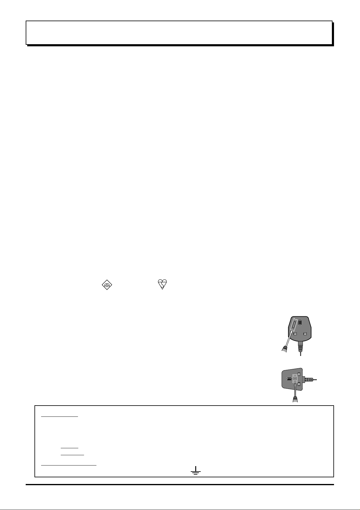
This appliance is supplied with a fitted three pin mains plug for your safety and convenience. A 5 amp fuse is fitted
in this plug. If the fuse is replaced then the replacement fuse must be 5 amp rated and should be approved by ASTA
or BSI to BS1362.
Check for the ASTA mark or the BSI mark on the body of the fuse.
If the fitted plug has a removable fuse cover you must ensure that it is refitted when the fuse is replaced. If you lose
the fuse cover the plug must not be used until a replacement cover is obtained. Replacement fuse covers can be
purchased through your local Panasonic dealer.
If the fitted moulded plug is replaced, the fuse should be taken out and the cut-off
plug disposed of safely. There is danger of severe electrical shock if the cut off plug
is inserted into any 13 amp socket.
If a new plug is to be fitted please observe the wiring code as shown below.
If in any doubt please consult a qualified electrician.
How to replace the fuse (for plug type shown in example 1):
Lift out the removable fuse compartment with a screwdriver and replace the fuse, then refit
securely into the mains plug (see example 1).
How to replace the fuse (for plug type shown in example 2):
Lift open the fuse compartment, in the mains plug, with a screwdriver, and replace the fuse,
then press the fuse cover down securely (see example 2).
IMPORTANT: -
The wires in the mains lead of this appliance are coloured in accordance with the following code :-
BLUE : NEUTRAL BROWN : LIVE
Example 1
Example 2
As the colours of the wires in the mains lead of this appliance may not correspond to the markings identifying
the terminals in your plug, proceed as follows :-
1. The BLUE wire must be connected to the terminal marked ‘N’ or coloured black.
2. The BROWN wire must be connected to the terminal marked ‘L’ or coloured red.
IMPORT ANT NOTE:
three pin plug, marked with the letter ‘E’ or the earth symbol.
Under no circumstances should either of these wires be connected to the Earth terminal of the
4
Before Operating This Set
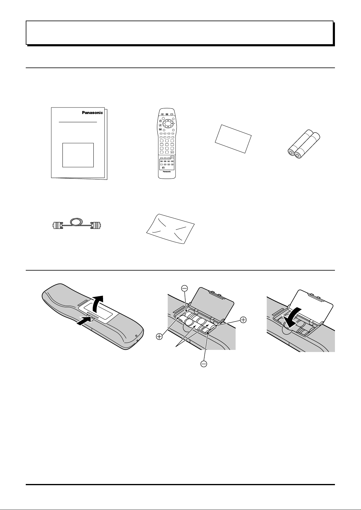
Supplied Accessories
Check the accessories before installations.
Operating Instruction book
•
(TQBC0502-1)
Remote Control Transmitter
•
(TNQE286)
123
456
7C89
0
N
?
Warranty Card
•
Batteries for the
•
Remote Control
Transmitter
(2 × R6 (UM3) size)
Display Cable
•
(K1HA26FA0002)
Polishing Cloth
•
(TPEX013)
Note:
If the cabinet is heavily soiled, wipe with a
supplied polishing cloth.
Fitting remote control batteries
123
Two
R6 (UM3) size
Open the battery cover Insert batteries - note
correct polarity (+ and -)
• Make sure that the batteries are fitted the correct way round.
• Do not mix old batteries with new batteries. Remove old, exhausted batteries immediately.
• Do not mix different battery types, i.e. Alkaline and Manganese or use rechargeable batteries.
Replace the cover
5
STR
F
TV AV
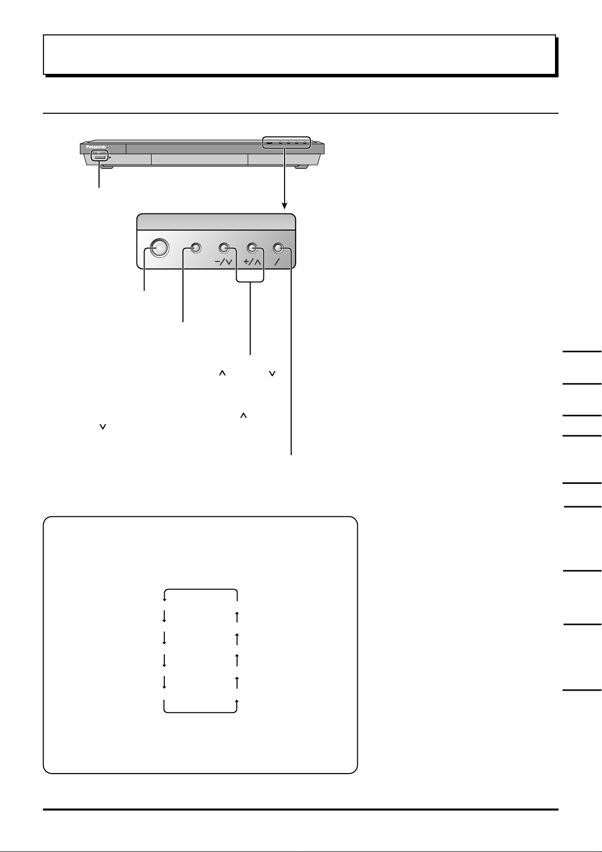
Basic controls
Top panel controls and Remote control
Receiver ON / Stand-by
Store
(see page 32)
Function selection
(see on this page below)
Volume Up (+), Down (-)/
Programme Number Up ( ), Down ( )
Volume adjustment which uses these
buttons is performed after pressing
Function button.
When programme number up ( )/down
( ) buttons on the top panel of the main
part are pressed in stand-by mode, this
set turns on.
TV/AVmode Selection
Press to select TV, AV input
signal modes sequentially.
Press to display programme position, programme
name, channel number, time, NICAM mode, Aspect
mode and programme table.
TV/TEXT Selection (see page 39, 40, 41)
Picture Menu (see page 20, 21)
Sound Menu (see page 22, 23)
Setup Menu (see page 24, 25)
Status button
Function selection
Displays the on screen display functions, press repeatedly to select
from the available functions.
The following adjustments can be accessed directly.
Volume
Contrast
Brightness
Colour
Sharpness
Notes:
• Tint : Displayed when receiving NTSC signals.
• Tuning mode : Not displayed during AV mode.
Tuning mode
Balance
Treble
Bass
Tint
TEXT Favourite Page Selection
(see page 40)
On Screen Help button (see page 17)
Store (see page 26 - 37, 40)
Stores some settings in TUNING
menus and TELETEXT.
Normalization (see page 21, 23)
The N button will recall settings
stored with STR.
6
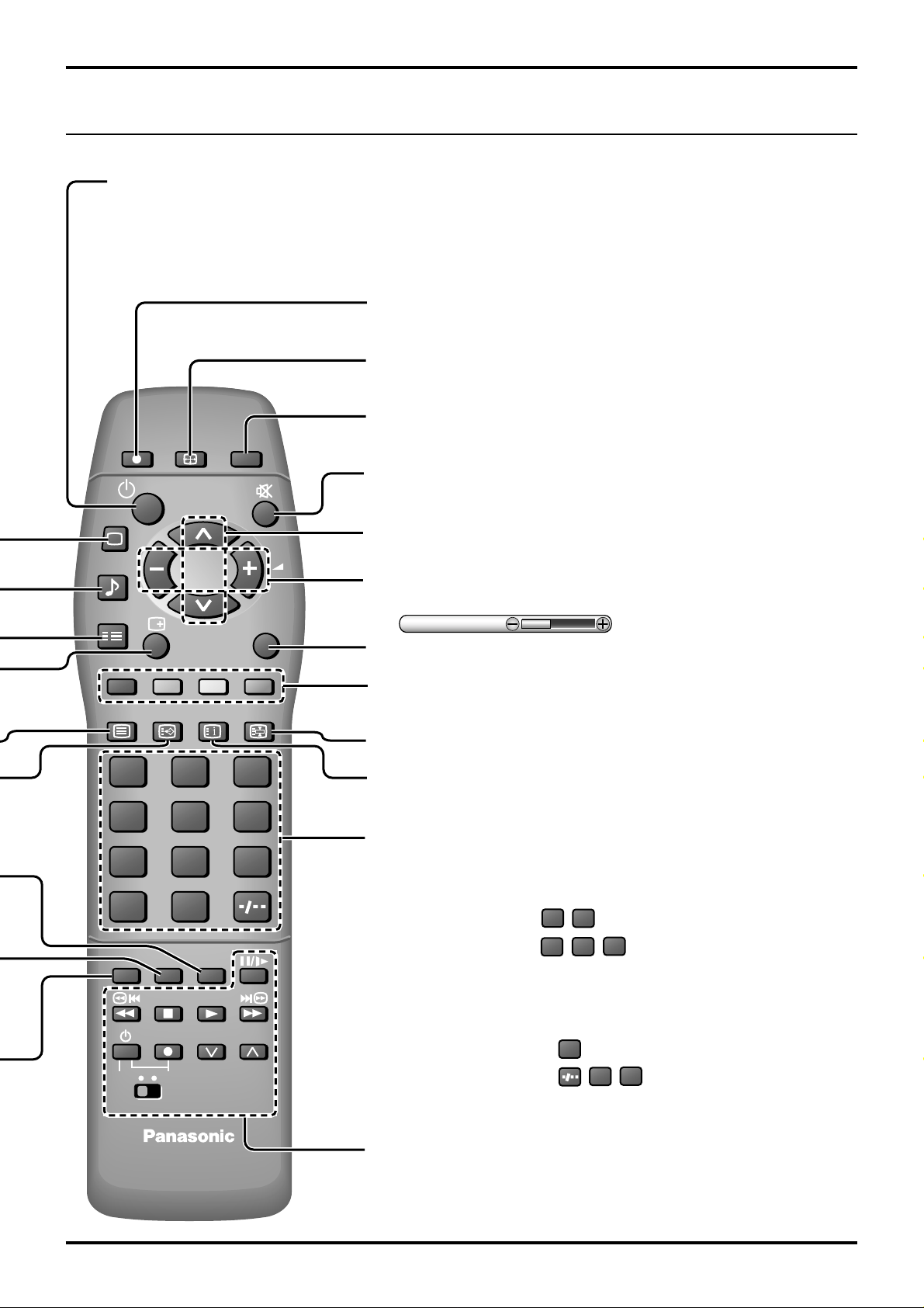
Remote control
Power (Stand-by)
This set must first be plugged into the wall outlet and
turned on at the power switch.
Press this button to turn this set On from Standby mode,
Press it again to turn this set OFF to Standby mode.
Direct TV Record button (see page 36)
Aspect Control (see page 18, 19)
Channel return
DIRECT TV REC
PICTURE
SOUND
SET UP
TV/TEXT
F.P.
ASPECT
INDEX
CH RETURN
TV/AV
HOLD
Switches to previously view to channel.
Sound Mute
Press to mute the sound completely the “Mute” character will appear.
Press again to restore the previous sound level, and cancel the mute.
Programme Number Selection
Press to select the next higher or lower Programme number.
V olume Adjustment
Press to increase or decrease the sound volume level.
Volume
TV/AV Mode Selection
Press to select TV, AV input signal modes sequentially.
Coloured buttons used for Programme edit (see page 28, 29, 30)
Teletext functions (see page 39, 40, 41)
AV Selection
TEXT hold (see page 40)
Basic controls
Note:
• It is also possible to turn this set On from STANDBY
mode by pressing the “Direct Programme Number
Selection” Buttons (0-9) on the Remote Control.
123
456
7
C
N
DVD VCR
89
VCR
0
STR HELP
?
PROGRAMMEREC
TEXT Index (see page 40)
Direct Programme Number
• Direct Programme Number Selection
You can select the number directly by pressing the “C” button and
corresponding programme number buttons.
C
Channel Number 8.......
Channel Number 36.....
• Direct Programme Number Selection
You can select the number directly by pressing “Number 0-9” buttons or
by pressing “Two Digit” and “Number 0-9” buttons.
Programme Number 8 .....
Programme Number 12....
VCR/DVD Control
(see page 38)
8
,
3
C
, ,
8
, ,
6
2
1
7
Quick start Guide
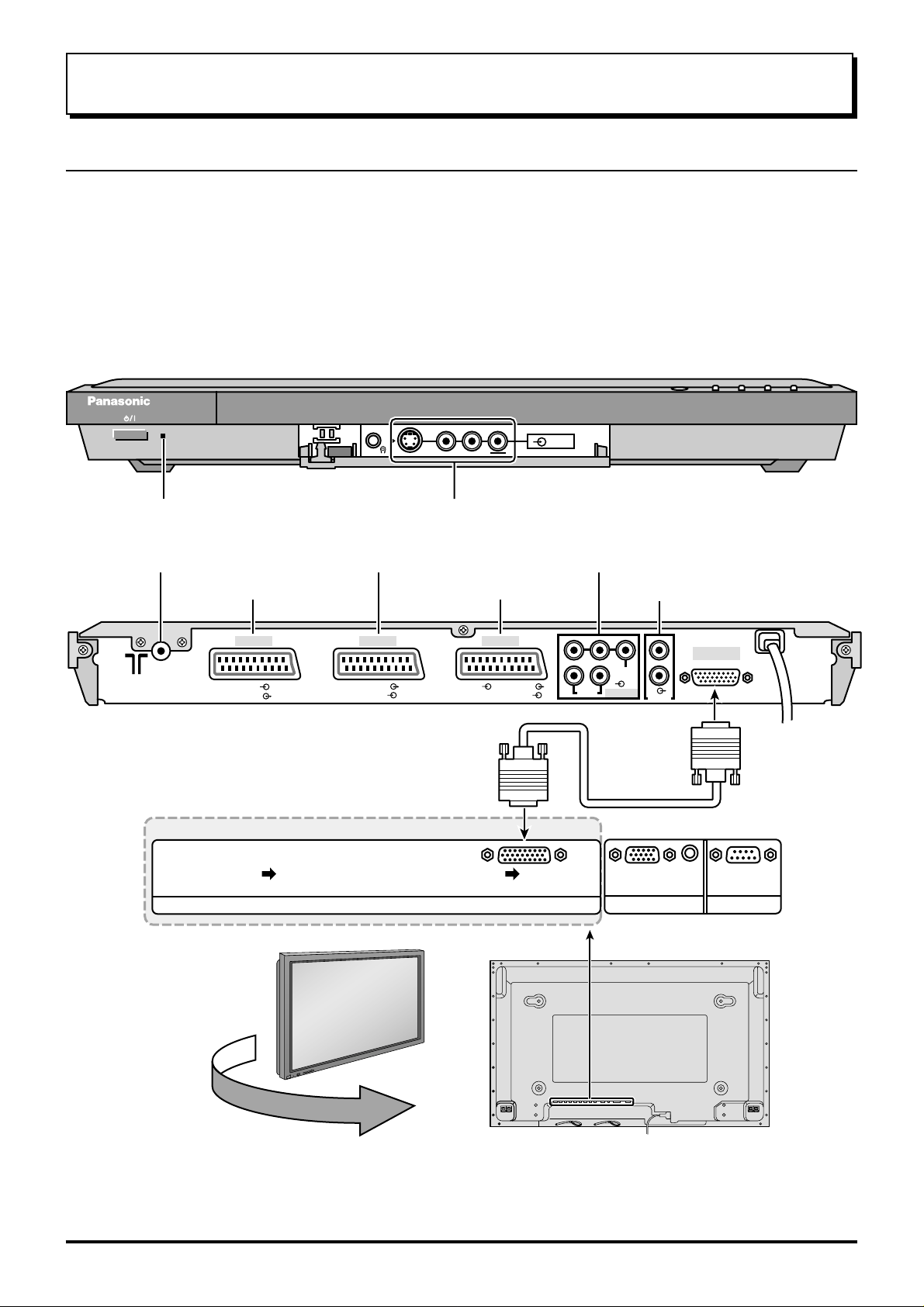
1. Connection of Receiver to TUNER Terminal Board
(1) This Receiver is only for Panasonic Plasma Display with a TUNER Terminal Board.
(TY-42TM5H, TY -37TM5H)
(2) And the TUNER Terminal Board (TY-42TM5H, TY-37TM5H) is compatible only with the products given below
and those that will be sold hereafter.
(TH-50PHW5B, TH-42PHW5B, TH-42PW5B, TH-37PW5B)
(3) When DISPLA Y OUT of this set and TUNER IN of a plasma Display are connected, an input select can not be
performed in a Plasma Display. Please perform an input select by this set.
The PC IN terminal and SERIAL terminal on the back of a Plasma Display cannot be used.
The INPUT select, Volume Up ‘+’ and Down ‘-’ of the front of a Plasma Display do not operate.
Power-Indicator
Antenna Input terminal
(see page 9, 10, 11)
AV1 Scart socket (In/Out)
RGB
VIDEO
TUNER Terminal Board
(TY-42TM5H / TY-37TM5H)
S-V
VLR
AV3 input terminals
Video Camera Cable terminal
AV2 Scart socket (In/Out)
AV4 Scart socket (In/Out)
AV1 AV2 AV4
VIDEO
S-VIDEO
RGB VIDEO
S-VIDEO
AV3
AV4C COMPONENT Input
Audio Output
PRPBYL
R
AUDIO
VIDEO
AV4C
RL
DISPLAY OUT
AUDIO OUT
AUDIO
Display out
terminal
TUNER IN
+
L
O
V
—
T
U
P
N
I
Y
B
D
N
A
/
T
S
-
N
O
R
R
E
R
E
W
W
O
O
P
P
G
SERIALPC IN
Back view of Wide Plasma Display
Note:
Install the Receiver at least 15.7 inch (40 cm) away from the Wide Plasma Display to avoid interference.
Be sure the power to the Wide Plasma Display and Receiver is OFF before connecting cables.
8
Quick start Guide
2. Choose Your Connection Type
Connection and setting up options
• If connecting this set using an RF cable only, see below.
• If connecting this set using Scart and RF cables, see page 10.
• If connecting this set to a Q-Link (or Q-Link compatible) VCR, see page 10.
• If connecting this set to a Q-Link (or Q-Link compatible) VCR and a satellite receiver, see page 11.
What is Q-Link?
Q-Link allows direct communication between the set and a Q-Link (or Q-Link compatible) VCR, this will enable
features such as downloading of tuning information from the set to the VCR.
When using a “NEXTVIEWLINK” VCR the main features possible are the following:
• Preset Download Downloading of tuning information from the set to the VCR.
• Direct TV Record
When using a “Q-Link” VCR the main features possible are the following:
• Preset Download Downloading of tuning information from the set to the VCR.
• Direct TV Record For immediate recording of the current program (What You See Is What You
• TV/VCR Auto Power On When the VCR plays a tape the set will automatically switch On (From Stand-
• VCR Auto Power Stand-by When the set is switched into Stand-by, the VCR will also switch into Stand-by.
• VCR Image view On If the set is in Stand-by mode and the VCR sends a menu to be displayed on
For immediate recording of the current program (What You See Is What You Record).
Record).
by) and select the AV2 input.
the TV screen (e.g. Main menu), the set will automatically switch On and the
menu will be displayed.
This set will also communicate with other VCRs that bear the following logos:
• “DATA LOGIC” (a trademark of Metz Corporation).
• “Easy Link” (a trademark of Philips Corporation).
• “Megalogic” (a trademark of Grundig Corporation).
• “SMARTLINK” (a trademark of Sony Corporation).
These VCRs may support some or all of the above funcitons. Refer to the VCR operating instruction book.
Further information on Q-Link can be found on page 36.
In order for Q-Link to function correctly, the Scart cables must be connected in a certain way, dependent on
whether the set is being connected to a VCR or to a VCR and Satellite Receiver.
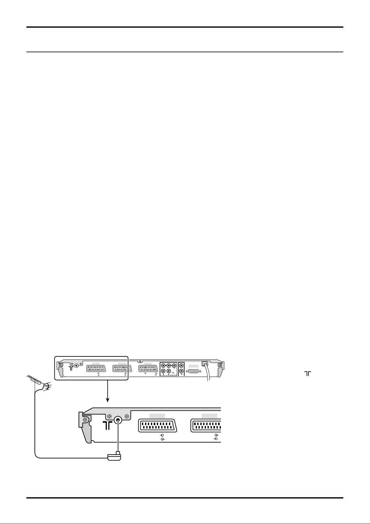
1. Connecting this set directly to an ANTENNA only
RF connection
Connect the Antenna lead into this set
Antenna Input terminal ( ).
ANTENNA
(Not Supplied)
AV1 AV2 AV4
RGB
VIDEO
VIDEO
S-VIDEO
RGB VIDEO
PRPBYL
RL
AUDIO
S-VIDEO
AV1 AV2
DISPLAY OUT
R
VIDEO
AV4C
AUDIO OUT
Antenna Lead
RGB
VIDEO
VIDEO
S-VIDEO
9
Quick start Guide
2. Connection of Receiver and VCR using Scart and RF cables
RF connection
Connect the ANTENNA to the Antenna Input
ANTENNA
(Not Supplied)
Antenna
Input terminal
Receiver
AV1 AV2 AV4
RGB
VIDEO
VIDEO
S-VIDEO
RGB VIDEO
Antenna
Output
terminal
PRPBYL
RL
AUDIO
S-VIDEO
AV1,AV2,AV4
Scart sockets
To Display
R
VIDEO
AV4C
AUDIO OUT
DISPLAY OUT
AV1
Scart socket
terminal of the VCR and an RF cable from the VCR
Antenna Output terminal to this set Antenna Input
terminal ( ).
Scart Connections
The VCR can also be connected to this set using
a Scart cable if you are using a Scart equipped
VCR.
• Use this set’s AV1 Scart socket for a VCR.
• Use this set’s AV2 Scart socket for an S-Video
VCR.
• Use this set’s AV4 Scart socket for an S-Video
VCR.
Antenna Lead
Antenna
Input
terminal
Notes:
• Additional equipment and cables are not supplied.
• Further details of audio / video connections can
be found on pages 42 and 43.
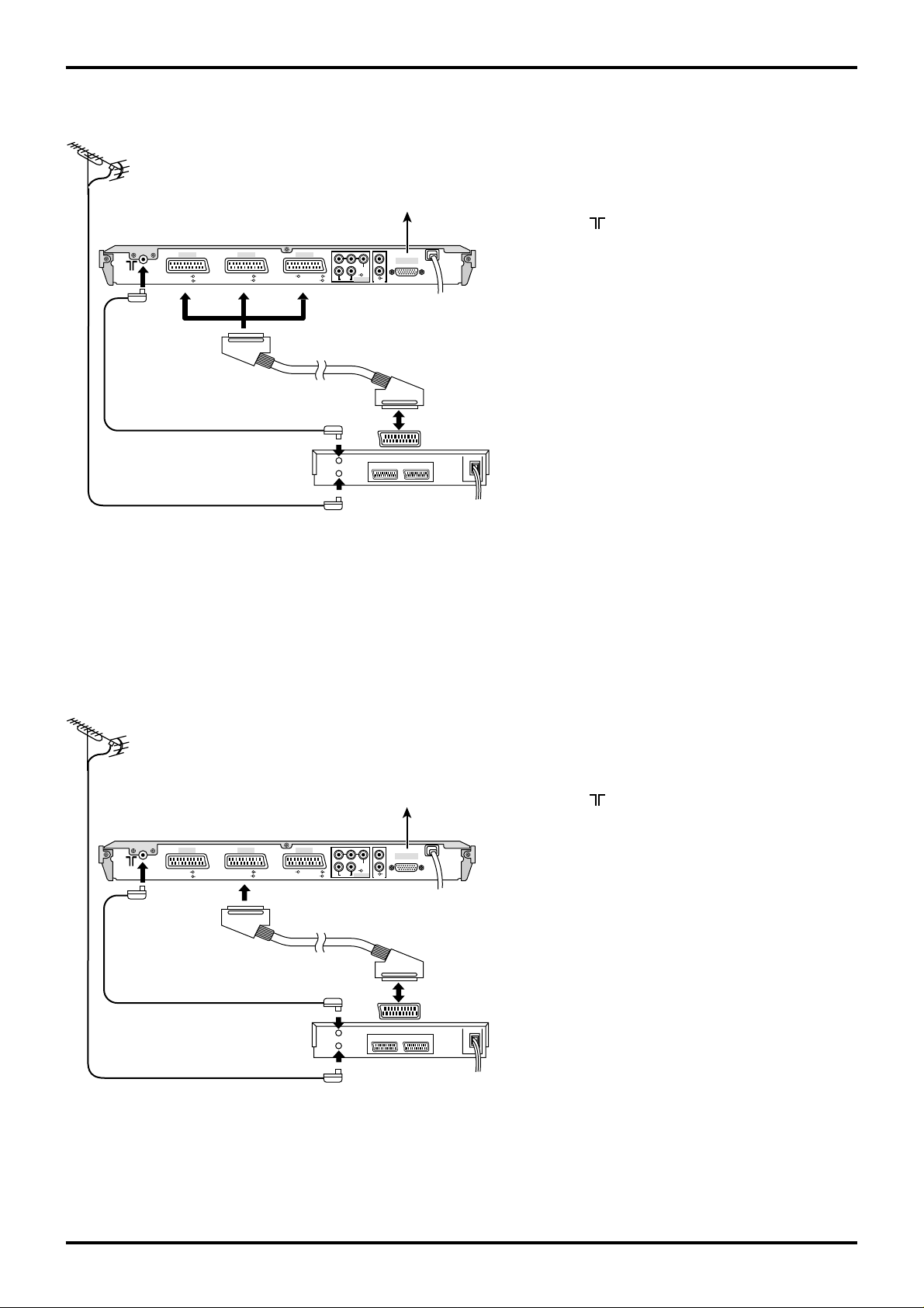
3. Q-Link connection of Receiver and VCR using Scart and RF cables
RF connection
Connect the ANTENNA to the Antenna Input
VCR
ANTENNA
(Not Supplied)
Antenna
Input terminal
Receiver
AV1 AV2 AV4
RGB
VIDEO
VIDEO
S-VIDEO
RGB VIDEO
Antenna
Output
terminal
PR PB YL
RL
AUDIO
S-VIDEO
AV2
Scart sockets
To Display
R
VIDEO
AV4C
AUDIO OUT
DISPLAY OUT
AV1
Scart socket
terminal of the VCR and an RF cable from the VCR
Antenna Output terminal to this set Antenna Input
terminal ( ).
Scart connection
The VCR must be connected to the AV2 Scart
socket of this set using a ‘fully wired’ Scart cable.
Note:
If using a ‘Q-Link’ VCR then the A V1 Scart socket
of the VCR must be connected to the AV2 Scart
socket of this set. If your VCR is not a ‘Q-Link’
VCR, please consult your VCR operating instruction book.
10
Antenna Lead
VCR
Antenna
Input
terminal
Notes:
• Additional equipment and cables are not supplied.
• Further details of audio/ video connections can
be found on page 42 and 43.
• Further information for VCR and Satellite
Receiver installation with this set can be found
on page 11.
Quick start Guide
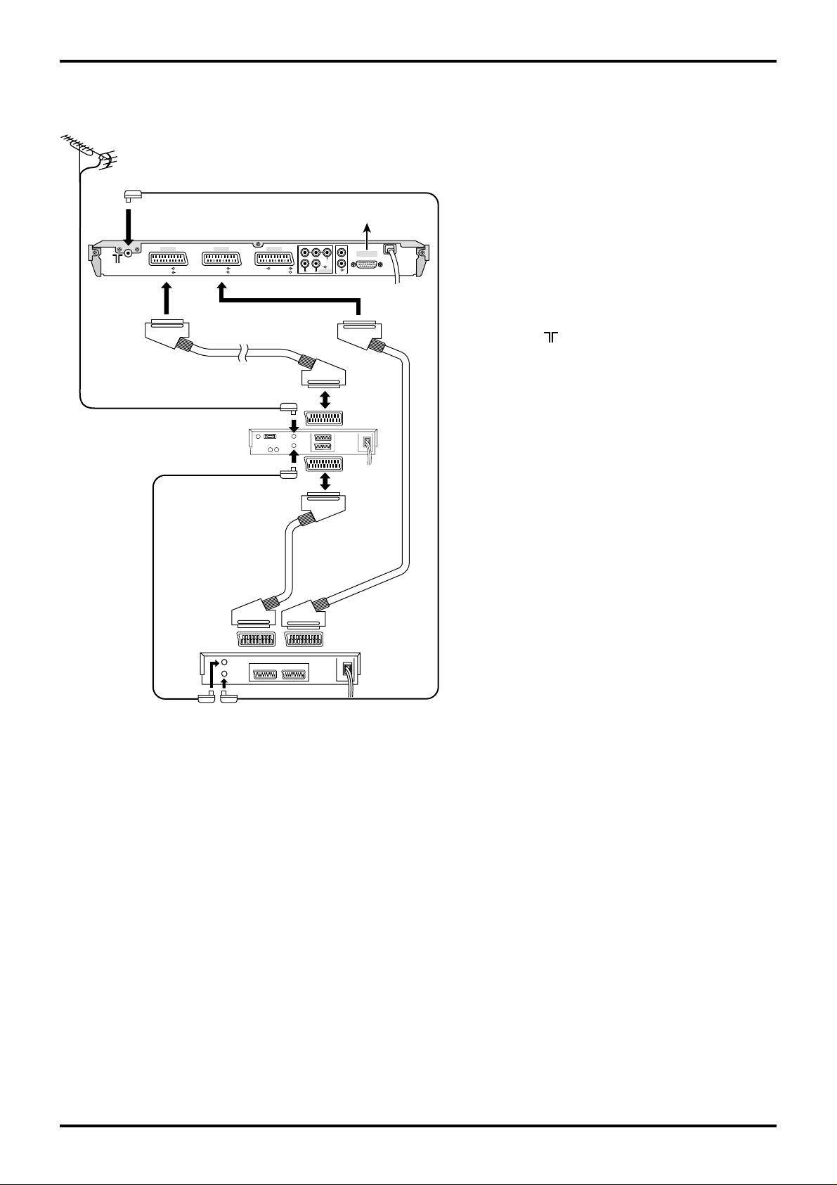
4. Q-Link connection of Receiver, VCR and Satellite using Scart and RF cables
ANTENNA
(Not Supplied)
Antenna
Input
terminal
AV1 AV2 AV4
RGB
VIDEO
AV1
Scart
socket
Antenna Lead
Receiver
VIDEO
S-VIDEO
Antenna Input
terminal
Satellite
Receiver
Antenna Output
terminal
RGB VIDEO
S-VIDEO
Scart socket
PRPBYL
VIDEO
RL
AV4C
AUDIO
AV2
To Display
DISPLAY OUT
R
AUDIO OUT
TV
Scart
socket
VCR
Scart
socket
For Q-Link to function correctly this set, VCR and
Satellite Receiver must be connected as shown
in the diagram below.
RF connections
• Connect an RF cable to the Antenna Input
terminal of the Satellite Receiver.
• Connect an RF cable from the Antenna Output
terminal of the Satellite Receiver to the Antenna
Input terminal of the VCR.
• Connect an RF cable from the Antenna Output
terminal of the VCR to this set Antenna Input
terminal ( ).
Scart connections
‘Fully wired’ Scart Cables should be used for all of
the Scart connections.
• The AV2 Scart socket of the VCR must be
connected to the VCR Scart socket of the
Satellite Receiver.
• The TV Scart socket of the Satellite Receiver
must be connected to the AV1 Scart socket of
this set.
AV2
Scart
socket
Antenna
Input
terminal
Antenna
Output
terminal
AV1
Scart
socket
Note:
If using a ‘Q-Link’ VCR then the AV1 Scart socket
of the VCR must be connected to the AV2 Scart
socket of this set. If your VCR is not a ‘Q-Link’
VCR, please consult your VCR operating
instruction book.
VCR
Notes:
• Additional equipment and cables are not supplied.
• Further details of audio/ video connections can
be found on pages 42 and 43.
11
Quick start Guide
3.
Preparing the Plasma Display (Refer to Operating Instructions of the Plasma Display)
Connecting the plug to the Wall Outlet
Push the Power switch on the Plasma Display to turn
the set on Power-On.
Power Indicator: Green
INPUT
—
VOL
+
R - STANDBY
G POWER ON
R - STANDBY
G - POWER ON
Power Indicator
Remote Control Sensor
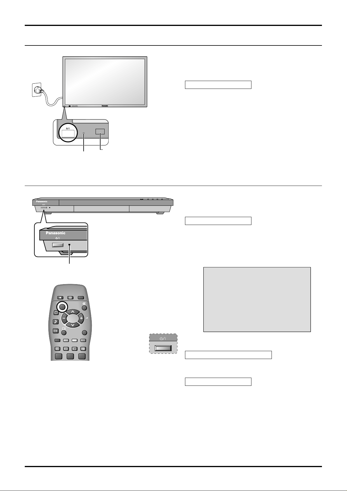
4. Power On/Off
Power-Indicator
DIRECT TV REC
ASPECT
CH RETURN
PICTURE
SOUND
SET UP
TV/AV
Connecting the plug to the Wall Outlet
Push the Power switch on this set to turn the set on
Power-On.
Power Indicator: Green
Example: The screen below is displayed for a while
after this set is turned on. (setting condition
is an example.)
For VIDEO / COMPONENT / TV INPUT:
1
12
TV/TEXT
F.P.
INDEX HOLD
123
Press the POWER button on the remote control to turn
this set off.
Power Indicator: Red (standby)
Press the POWER button on the remote control to turn
this set on.
Power Indicator: Green
Turn the power to this set off by pressing this power
switch on this set, when this set is on or in standby
mode.
Note:
The Receiver will still consume power as long as the
power cord is inserted into the wall outlet.

5. Auto setup
If this set has not been programmed for you then Auto setup will begin, your
stations will be located, sorted into order and stored ready for use (refer to page
AUTO SETUP IN PROGRESS
SEARCHING:PLEASE WAIT
21 68
SETUP : Return to tuning menu
TV/AV : To exit
31).
6. This set to VCR download
If a Q-Link, NEXTVIEWLINK or compatible VCR has been connected to the AV2
socket before starting Step 1, programme information will be downloaded to the
TV −> VCR DOWNLOAD IN PROGRESS
PLEASE WAIT
Programme : 63
Remote control unavailable
VCR.
Downloaded tuning data will match the television’s.
Not all VCRs support this download of programme information, some may require
to be started manually. Refer to the VCR operating instruction book.
If a VCR other than those described above has been connected, then there will
be no download operation.
Quick start Guide
Notes:
If the VCR has not accepted download data from this set, you may need to select the Download option from the
VCR’s menu system.
Refer to the VCR operating instruction book.
If Q-Link is not operating correctly, check the following:
• The Scart cable is connected to this set’s AV2 Scart socket.
• The Scart cable is connected to the VCR’s compatible (Q-Link, NEXTVIEWLINK or similar technology) Scart
socket.
• The Scart cable is a ‘fully wired’ type.
For further information on Q-Link and connecting equipment, see pages 9, 10, 11, 36 and 42.
• The sorted programme order depends upon the TV signal, the broadcasting system, and reception conditions.
If the order is not to your preference it can be rearranged. Refer to the Programme edit menu - see page 27 for
details.
13
Quick start Guide
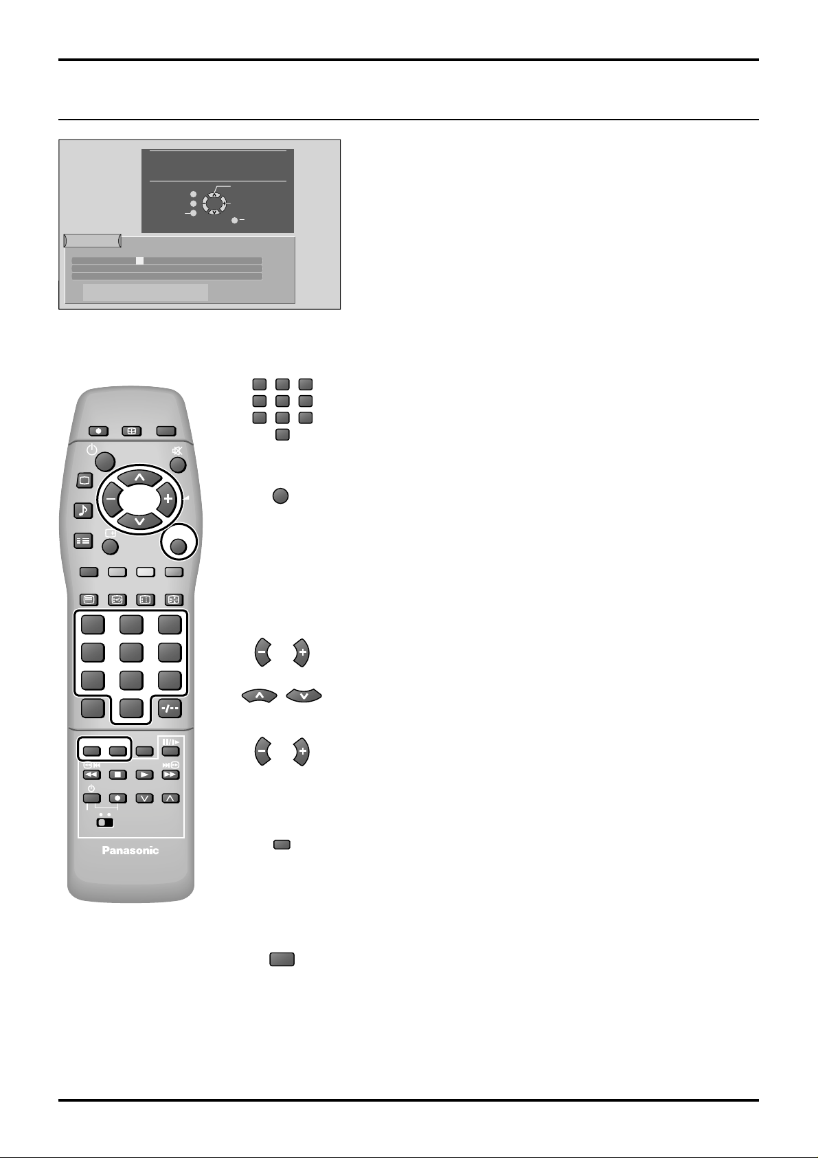
7. Owner ID
You now have the opportunity
to enter your details and
help the police crack crime
see instruction book
Return
Owner ID
PIN NUMBER:
HOUSE NO:
POST CODE:
ABCDEFGHIJKLMNOPQRST
UVWXYZ
DIRECT TV REC
PICTURE
SOUND
SET UP
∗∗∗∗
NAME:
∗∗∗∗∗∗∗∗∗∗∗∗∗∗
∗∗∗∗∗∗∗∗∗∗∗
∗∗∗∗∗∗∗∗∗∗∗
+− .
0123456789
ASPECT
CH RETURN
Change
Character
Select
character
’STR’ Button - Store Owner ID
TV/AV
TV/AV
Exit
123
456
789
VCR
0
TV/AV
As an added feature, this TV has the option of entering a
security code (Owner ID) and personal details into its memory ,
so that in the unfortunate event of theft it will help the police to
trace the owner.
Enter required 4 digit Owner ID PIN NUMBER (using 0 to 9 on the
remote control)
Press the TV/A V button at any time to exit the Owner ID feature without
saving any information you may have entered.
TV/TEXT
F.P.
INDEX
HOLD
123
456
7
89
VCR
0
C
HELP
STR
N
DVD VCR
?
PROGRAMMEREC
STR
N
Enter NAME, HOUSE NUMBER and POSTCODE
If a 4 digit PIN NUMBER was entered above, you will be taken
automatically to the NAME line.
If not, move to the NAME line.
Change character.
Select character position.
Repeat above until NAME, HOUSE NUMBER and POSTCODE are
entered.
Press STR to store the details
Press STR again, when you are asked "Are you sure?"
For further information on Owner ID, including how to view the details
you have stored, see page 35.
A space is provided on page 35 to write down your PIN NUMBER for
future reference.
We recommend that as soon as you have stored Owner ID details (or
have exited the feature), the picture controls are reset to normal viewing
levels. To do this, press the “N” button, found under the remote control’s
pull down flap.
14

8. The two basic functions
You are now ready to begin viewing programmes.
The cursor controls provide the two basic functions:
Quick start Guide
Adjust Volume
Change
Programme
15
 Loading...