

Page 1

English
Operating Instructions
High Definition Digital Receiver
Model No.
TU-HDT206A
Please read these instructions before operating your set and retain them for future reference.
The illustration shown is an image.
25001-B2401 26 March 2007 v3.2
Page 2

Operating Instructions
TU-HDT206A
Welcome
We hope you have many years of enjoyment from your new Panasonic HD Digital Receiver.
The following instructions will enable you to quickly set up and install the equipment and begin
receiving the terrestrial digital TV services in your reception area.
The availability of digital TV services in your area is dependent upon the digital signals available
from your local broadcasters and the condition of your aerial system.
This Digital Receiver is intended for the reception of Digital TV picture and sound
signals.
If the Digital Receiver is exposed to drastic temperature changes this can cause liquid
condensation. Allow the condensation to evaporate before plugging in the Digital Receiver to
the power supply.
Do not place the Digital Receiver in the immediate vicinity of a heat source or in direct
sunlight as this will prevent appropriate cooling.
To prevent fire, never place any type of candle or naked flame on top of or near the Digital
Receiver.
Warnings and precautions
Only install the receiver in a safe location (away from any wet environment).
Only plug the receiver into an AC 220V to 240V power supply.
Do ensure the AC plug is fully inserted into the socket.
Do not touch the AC cord or plug with wet hands.
Unplug the receiver immediately if smoke or a strange smell is emitted from the receiver.
・ Do not attempt to repair the receiver by yourself; have the receiver repaired at your local
Panasonic repair agent.
Unplug the receiver if any foreign substance or water enters the unit, or if the unit is damaged
and the covers are broken open.
Keep liquids and other foreign objects away from the receiver.
・ Do not place containers with water (flower vase, cups, cosmetics etc) or small metallic
objects on the receiver.
Do not insert or allow to fall into the receiver any foreign objects (fire or shock may result).
In the event of a thunder storm or lightning, do not touch the receiver or the cables.
Do not plug in the receiver to the AC supply if the AC power cord or power plug is damaged.
Do not pull on the AC lead; hold the AC plug to remove it from the AC socket.
When you move the receiver, be sure to unplug from the AC socket.
Do not cover or obstruct the ventilation slots of the receiver.
・ Install the receiver in a location that allows ventilation of heat from it.
Do not put heavy objects on the top of the receiver.
When you clean this unit, be sure to unplug the power cord from the AC outlet for safety.
Wipe the AC plug with a dry cloth at regular intervals. (Moisture and dust may lead to fire or
electric shock.)
Handle the remote control and it’s batteries as below:
1. Use only the specified type of batteries, and do not mix battery types (such as alkaline or
manganese).
2. Do not mix old and new batteries.
3. Do not use rechargeable batteries.
4. Avoid contact with liquids or moisture.
5. Remove the batteries if not using the remote control for a long period of time.
6. Do not allow the + and - terminals of the batteries to come into contact with metallic objects.
7. Do not short-circuit, heat or disassemble the batteries, or dispose of them into liquids or
fires.
2
Page 3

Operating Instructions
TU-HDT206A
Contents
1
Introduction............................................................................................4
1.1 IMPORTANT: First time Installers..........................................................4
2
The Digital Receiver ..............................................................................4
2.1 Front Panel............................................................................................4
2.2 Rear Panel ............................................................................................5
2.3 Box Contents.........................................................................................5
3
The Remote Controller ..........................................................................5
3.1 Preparing the Remote Controller...........................................................5
3.2 Remote Control Button Functions:.........................................................6
4
Installation of the Digital Receiver..........................................................7
4.1 Connection of the Digital Receiver.........................................................7
4.2 HD STB Start Up...................................................................................9
4.3 Automatic Channel Tuning.....................................................................9
5
Operating Instructions: Knowing your basic controls............................10
5.1 Switching On Your Digital Receiver.....................................................10
5.2 Display Information Banner..................................................................10
5.3 Program Guide....................................................................................11
5.4 Changing or Selecting Channels .........................................................11
5.5 Audio Mode Selection..........................................................................12
5.6 SD Picture Format Selection................................................................12
5.7 SD Onscreen Display ..........................................................................13
6
Using the Main Menu...........................................................................13
6.1 Favourites List.....................................................................................14
6.2 Video Menu .........................................................................................14
6.3 Audio Menu .........................................................................................16
6.4 Power Saving Setup............................................................................17
6.5 Tuning Menu........................................................................................17
6.6 Diagnostic Information.........................................................................19
7
Teletext Operation...............................................................................19
8
Glossary..............................................................................................21
9
Troubleshooting...................................................................................22
10 Technical Specifications......................................................................25
WARRANTY – Australia only........................................................................27
3
Page 4
Operating Instructions
TU-HDT206A
1 Introduction
This Operating Instruction Book is the GUIDE to your digital receiver. In it you can
find comprehensive descriptions of the functions of your receiver. Once you become
acquainted with the operations of your digital receiver, you will only need this manual
for reference.
1.1 IMPORTANT: First time Installers
IMPORTANT: For first time installers, please read Section 4, “Installation of the
Digital Receiver”, to learn how to connect your digital receiver to other A/V equipment.
Once you have completed the setup, go to Section 6.2, “Video Menu”, to select
various system settings according to your personal preference, and Section 6.3,
“Audio Menu” and Section 6.5, “Tuning Menu”, to set your region for correct current
time and to conduct channel search.
2 The Digital Receiver
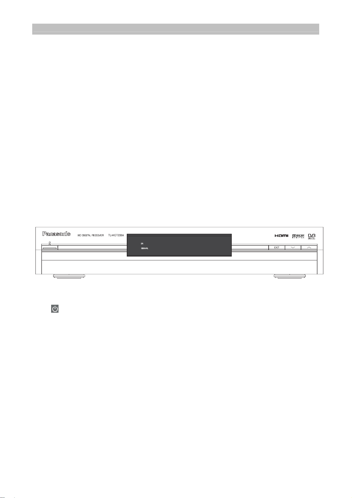
2.1 Front Panel
(Power Button): Turns the digital receiver On / Off (Standby mode).
EXIT Button: To return to the previous menu from the sub-menus.
Display: Shows the logical channel number when the box is switched on.
Front Panel Arrow Buttons: / buttons to select channels or settings within the
menus.
Stand-By Indicator (LED): Lights red in Stand-By mode. When the digital receiver is
working the LED becomes green.
Infrared (IR) Indicator (LED): The red LED flashes, indicating the box has received
a command from the remote control.
Signal Indicator (LED): When a signal of a channel is successfully acquired the
yellow LED will light up.
4
Page 5
Operating Instructions
TU-HDT206A
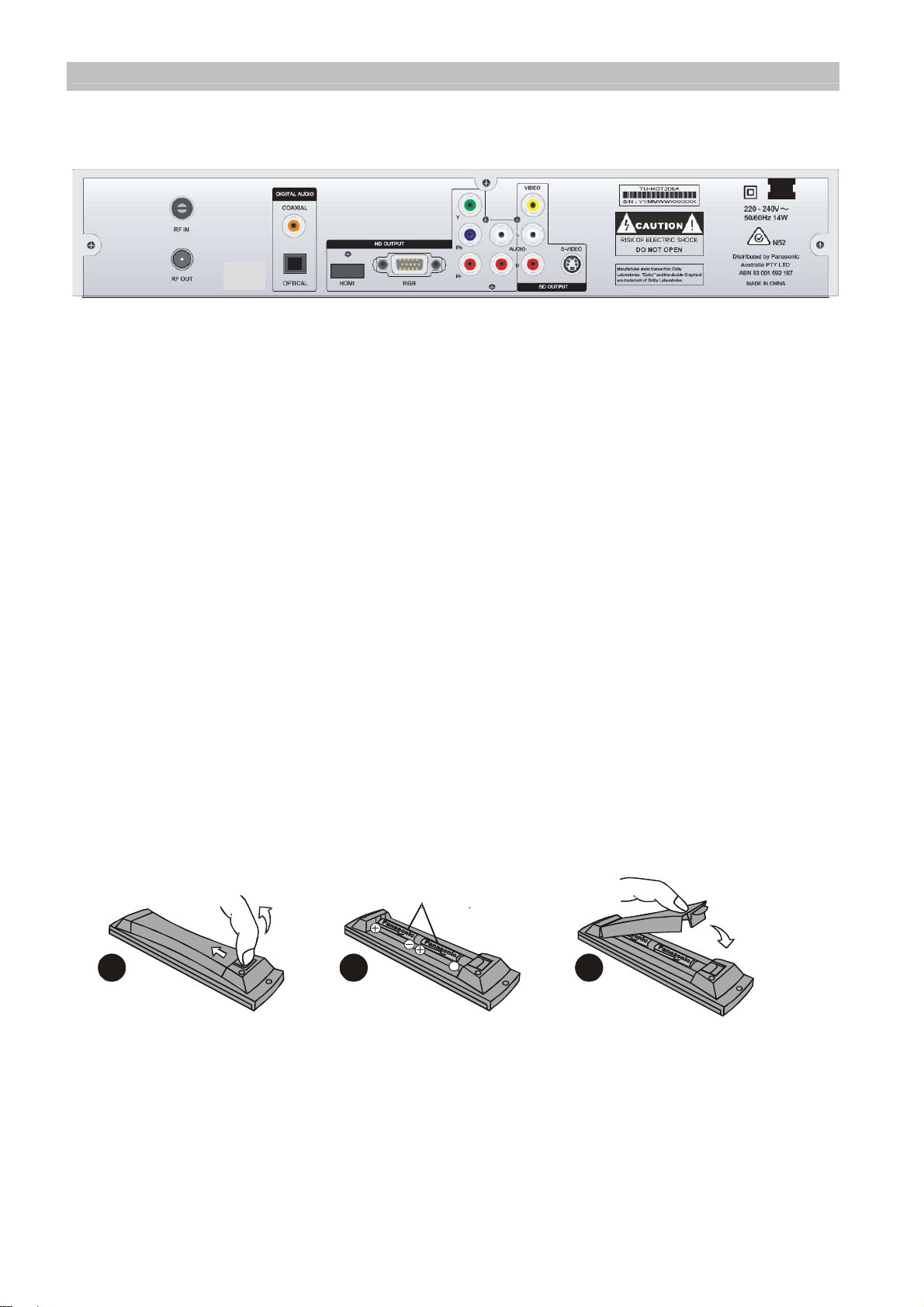
2.2 Rear Panel
AC Power Mains: 220 to 240 V; 50 / 60 Hz
RF IN: For connection to cable from outdoor terrestrial antenna.
RF OUT: For connection to your TV antenna IN or Video Recorder RF IN.
S-VIDEO: Y/C video for connection to standard definition TV or Video Recorder.
VIDEO: Composite video output for connection to TV, Video Recorder or other A/V
Receiver.
AUDIO: Two sets of stereo audio outputs for connection to TV, Video Recorder or
other A/V Receiver.
YPbPr: Y/Pb/Pr component video for connection to high definition display.
RGB (15pin D): R/G/B/HS/VS video for connection to high definition display.
COAXIAL: Digital Audio output by coaxial for connection to AV processor.
OPTICAL: Digital Audio output by optical for connection to AV processor.
HDMI: Digital video and audio output for connection to high definition display.
USB Port: For software system maintenance (covered by sticker).
2.3 Box Contents
The box that contains your digital receiver should also contain the following items:
Remote Controller and batteries (AA Size)
RCA video cables (one white / red, and the other cable red / green / blue)
RF cable
User’s Manual with Warranty Information
3 The Remote Controller
3.1 Preparing the Remote Controller
2
1
1). Remove the cover of the battery compartment (on the back of the handset) by
2) Insert 2 AA (1.5 V) batteries according to the + and – markings indicated inside
3) Replace the cover.
Test the remote controller by pressing any key and check if the IR-LED (Red) on the
pushing the tab back and then lifting.
the battery compartment.
front panel of the receiver flashes.
2 x “AA”
3
5
Page 6
Operating Instructions
TU-HDT206A
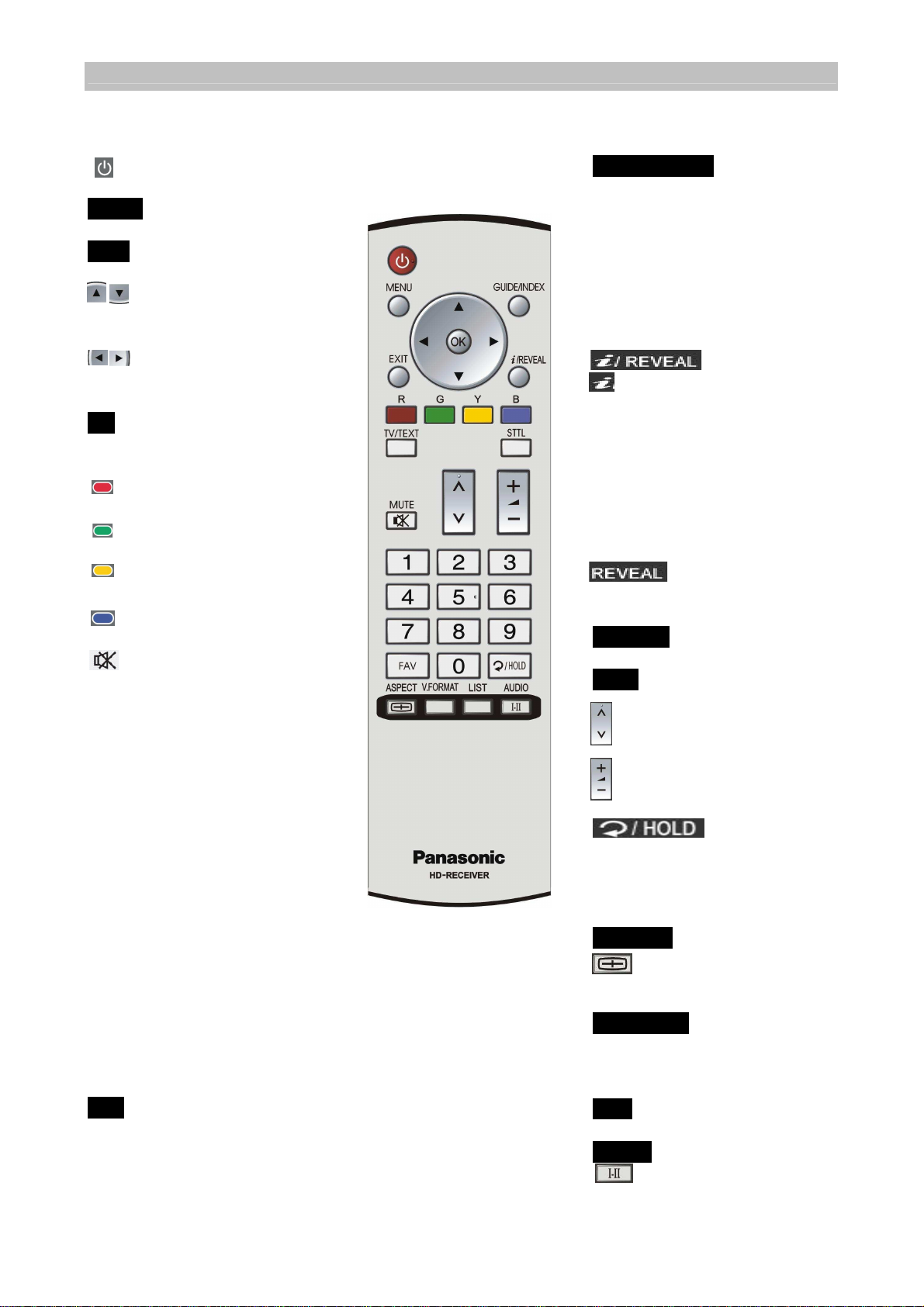
3.2 Remote Control Button Functions:
: To turn your receiver
on/off (standby mode).
MENU: To display the “Main”
Onscreen Display.
EXIT: To go back in the
menus.
Cursor buttons: To
select items in the
menus.
Cursor buttons: To cycle
through options within
the menus.
OK: To confirm choices and
selection of highlighted
item.
: (Red): Application
defined function key.
: (Green): Application
defined function key.
: (Yellow): Application
defined function key.
: (Blue): Application
defined function key.
: Mute function, to turn
on/off sound (only used
for analogue audio
output).
Number (0~9) keys: To select
channels directly.
Broadcasters have
allocated logical channel
numbers (LCN) to their
services based on their
service number identity.
The programs can be
selected by the LCN.
1: TEN,
2: ABC,
3: SBS,
5: TEN Regionals,
6: SEVEN Regionals,
7: SEVEN,
8: NINE Regionals,
9: NINE.
FAV: To select channels from
the favourites list.
GUIDE/INDEX: To obtain a
list of programs on
available channels. This
information is only
shown if your
broadcaster transmits
program information.
INDEX: To go to index
page in Teletext mode.
: To call up the display
information banner and
program synopsis
information. Also used in
program guide menu.
This information is only
available if the
broadcaster or network
transmits the information.
: Show the hidden
information in the
Teletext mode.
TV/TEXT: To toggle between
TV pictures and Teletext.
STTL: To turn closed captions
on/off.
: For changing channels.
: For volume adjustment
(only used for analogue
audio output, not HDMI).
: To toggle
between present and
previous channel.
HOLD: To stop current
page in Teletext mode.
ASPECT
:
Aspect ratio, to
change to 16:9, 4:3
letterbox or 4:3 centrecut mode.
V.FORMAT: To select the
different HD display
formats of 576p, 720p &
1080i. (see page 15)
LIST: To set up Favourites
AUDIO: To select the desired
audio sound track.
6
Page 7
Operating Instructions
(C)
HDMI Connection
(A) Aerial Connection
TU-HDT206A
4 Installation of the Digital Receiver
4.1 Connection of the Digital Receiver
The following illustrations show some examples for connecting this HD digital
receiver. Select the connection that is best suited for your needs. Many other
connections may be possible when optional devices such as RF cable splitters are
included in your system. These devices may cause signal degradation and, if too
many are used, poor quality picture and sound may result.
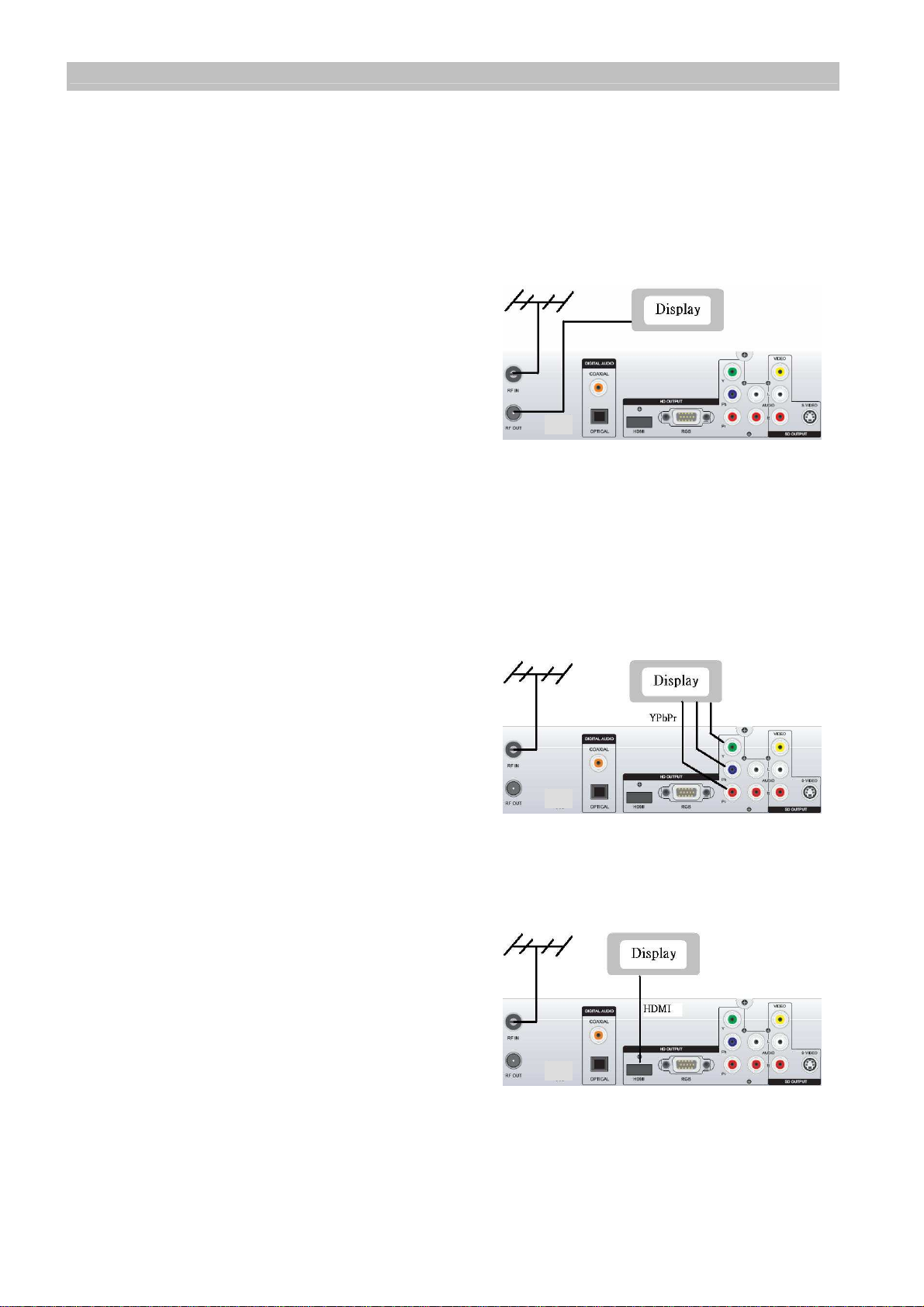
Terrestrial Antenna Cable Connection (A)
Connect the RF antenna cable to the HD
digital receiver RF IN connector. Also
connect the cable from RF OUT to the TV RF
IN connector on the rear of your television.
This connection allows your TV set to receive
normal analogue programs. (Refer to A)
Video Connections
The HD digital receiver has several types of video connections. Please select from
HDMI, YPbPr and RGB for high definition video, and VIDEO and S-VIDEO for
standard definition video. The HDMI, YPbPr and RGB sockets detect when a plug is
inserted and the digital receiver configures the video output to suit the connection
type made to the display.
YPbPr Connection (B)
Connect the YPbPr component video output
socket on your digital receiver to your display
device’s YPbPr component video input. Be
sure to match the colours on the RCA
sockets with the coloured plugs. (Refer to B)
At the start of the initial installation, the video
format is set as HD Format 576p. The video
format can be changed to other HD formats after
the installation is finished by “V Format” on the
remote control.
HDMI Connection (C)
Connect the HDMI output socket on your
digital receiver to your display device’s HDMI
input. The HDMI connection also includes
audio signals set at a fixed level. (Refer to C)
The HD digital receiver can also be
connected to a DVI input on a display.
Please check that DVI input can display the
digital receiver HD video formats. A HDMI to DVI
cable (not supplied) is required for this. Also the audio needs to be connected by the
RCA connector (red/white) cable. Note: If HDMI cable is removed when the digital
receiver is switched on, the OSD will NOT change to any other video output terminal.
The receiver must be switched off when the HDMI cable is removed.
(B) YPbPr Connection
7
Page 8

Operating Instructions
TU-HDT206A
RGB Connection (D)
Connect the RGB 15pin D socket to your
display device. (Refer to D)
Check the display video specifications,
many displays cannot show 50Hz TV
formats that the STB outputs.
Note: RGB Cable is not supplied.
Note: There is no RGB output signal when
component video (YPbPr) is connected.
(D) RGB Connection
VIDEO and S-VIDEO (E)
Connect the VIDEO output socket on your
digital receiver to your TV’s video input
socket.
Alternatively, connect the S-VIDEO (Y/C)
output socket on your receiver to your TV’s
S-Video input socket.(Refer to E)
Note: The cable is not supplied.
Note: VIDEO or S-VIDEO can be
(E) VIDEO / S-VIDEO Connection
connected to a VCR or DVD recorder if
they are not being used with a display. When an HD connection is made to the digital
receiver, there is no OSD on the VIDEO or S-VIDEO connection output pictures.
Audio Connections
DIGITAL AUDIO (F)
If the display device is equipped with Dolby
Digital audio and PCM audio decoding
capability, connect the DIGITAL AUDIO
output of the digital receiver to the display
device’s Digital Audio input using either the
OPTICAL or COAXIAL socket. (Refer to F)
Alternatively, connect the DIGITAL AUDIO
(F) DIGITAL AUDIO Connection
output to an A/V receiver with Dolby Digital
decoding and PCM decoding capability.
Note: The cable is not supplied.
Analogue Audio (G)
Connect the L & R AUDIO output RCA
sockets on the digital receiver to the stereo
L & R Audio inputs of the display device
and/or A/V receiver. (Not required with
HDMI).
(Refer to G). Please use the RCA sockets
associated with the video format (HD or SD)
(G) Analogue Audio Connection
that is connected to the display.
8
Page 9
Operating Instructions
TU-HDT206A
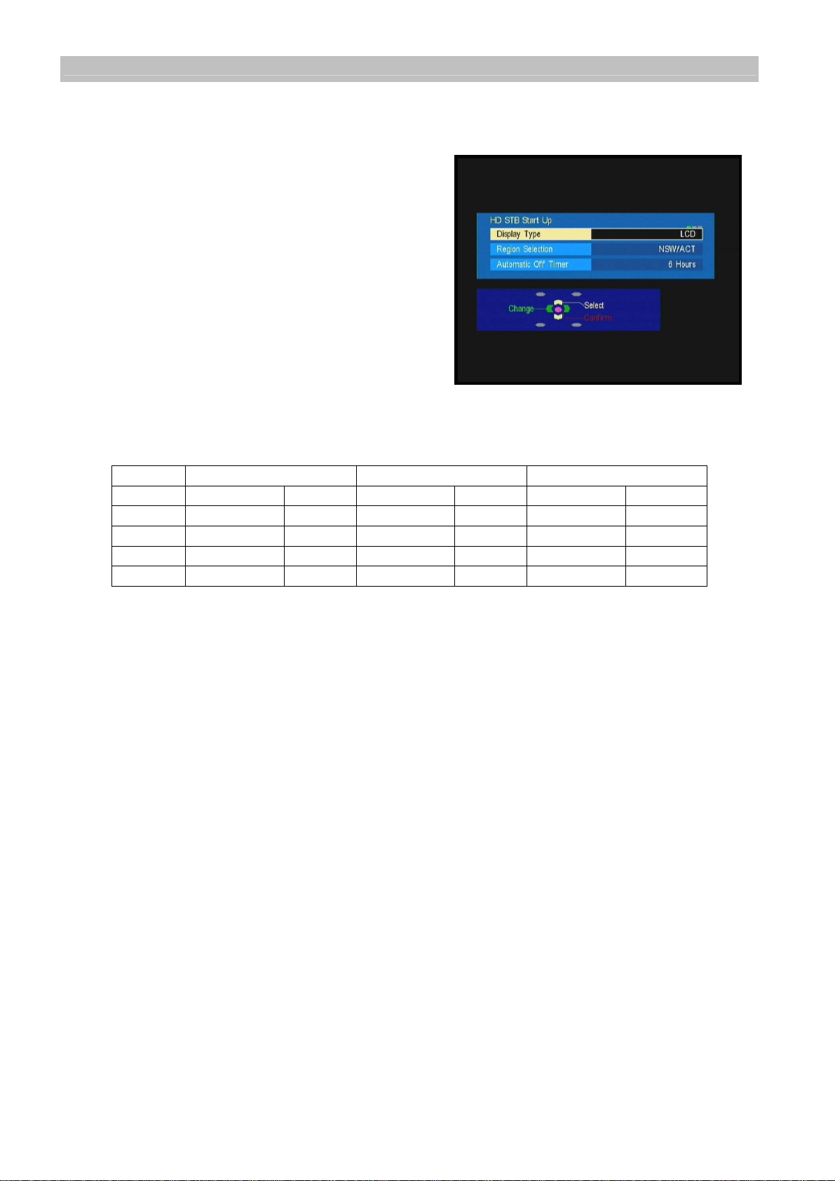
4.2 HD STB Start Up
Display Type
The first on-screen display of the installation
process will show Display Type selection.
Please change to the type of display the HD
digital receiver is connected to. The choice is
either LCD, PDP (Flat panel displays) or CRT
(eg Standard television).
Select using the cursor buttons on the
remote control keypad.
Note: Not all video formats are available in all
modes. The following table describes the
available formats in each mode.
CRT selection does not allow 720p video format.
HD (YPbPr & RGB) HD (HDMI) SD (VIDEO, S-VIDEO)
LCD/Plasma CRT LCD/Plasma CRT LCD/Plasma CRT
576i X X
576p X X X
1080i X X X
720p X X
Table 1: Output format table
Region Selection
The first time the digital receiver is installed, or after default settings are restored
(section 6.5 page18), please select the state or territory that you live in. This will
enable the digital receiver to display the correct local time.
Automatic Off Timer
This function requires a time to be set for the automatic shutdown of the digital
receiver. The receiver will automatic go into standby to save power. The time is
measured from the last received command sent to the receiver. The default setting is
6 hours.
After selecting the settings for Display Type, Region Selection and Automatic Off
Timer, press OK to confirm the selection. The digital receiver will automatically step
to the channel tuning process.
4.3 Automatic Channel Tuning
The first time the digital receiver is installed, or after default settings are restored, the
digital receiver will automatically scan for available digital services. This will take
around five minutes or so.
9
Page 10

Operating Instructions
TU-HDT206A
5 Operating Instructions: Knowing your basic controls
To become acquainted with the operations and functions of your receiver, please
learn how to use the control buttons on the Remote Control and the Front Panel.
The following segment is an introduction to features that you will most commonly use.
5.1 Switching On Your Digital Receiver
To switch on the digital receiver please, first plug the power lead into a 240V AC
socket. The digital receiver remains in constant “STANDBY” when plugged into a
240V supply. However it does require time to start up and so the picture and sound is
not immediately available when the on button is pushed.
Switch on your receiver by pressing either the button on the remote control or the
button on the front panel. While the digital receiver is in normal viewing mode,
the green LED lights up. When not using the digital receiver, put your equipment in
the “STANDBY” mode by pressing either one of the / buttons again. When the
red “STANDBY” LED lights up, it indicates the digital receiver is in “STANDBY” mode.
5.2 Display Information Banner
The Display Information Banner shows
information about the program that you are
currently watching. The banner appears
briefly whenever a new channel is selected
or when there is a problem with signal
reception. To show the banner, press the
button. Pressing
again will display the program synopsis. To
exit the synopsis, continue pressing the
button. Pressing the EXIT
button will remove the banner from the
screen at any time. The banner shows information about program, the time it is being
broadcast and the type of service. Pressing cursor left or right buttons will toggle
the synopsis to the next program information.
Banner Symbols
SD Standard Definition Picture
HD High Definition Picture
CC Closed Captions (note not programs have CC even if symbol is displayed)
TXT Teletext service is available with this program
I-II Program has MPEG and Dolby Digital Audio
Now Program that is being broadcast now
Next Program that is being broadcast next
Parental Guidance
The content ratings of programs are displayed on the information banner and the
electronic program guide. The ratings are P (pre-school), C (children), G (general),
PG (parental guidance), M (mature adult audience), MA 15+ (mature adult audience
15+), AV 15+ (adult, strong violence 15+) and R (restricted 18+).
However, not all transmissions carry ratings information to activate this function.
10
Page 11

Operating Instructions
TU-HDT206A
5.3 Program Guide
The Program Guide is a user-friendly feature
which displays the programs that will be
broadcast. To enter into the Program Guide,
press GUIDE/INDEX. In the Program Guide
on-screen display there are 2 formats, the first
displays NOW/NEXT and the second displays
a 7 day EPG.
Programs Schedule
The EPG is in classic terms a TV Guide,
except it is presented on your TV screen. The
EPG allows you to see in advance, depending
on services provided by the broadcaster, to the
next program, or a few days or up to one week
of TV programs and program information.
There are 2 Guide onscreen displays types,
the first shows the ‘now’ program and the ‘next’
program of all the channels. The second Guide
display shows the programs up to one week in
the future of the channel that is being received.
Push the remote control “Guide” button to
display the Electronic Program Guide (EPG).
Use the arrow keys on the remote control to
access the EPG information of the various channels and programs.
In the list, highlight the desired program by pressing the arrow buttons. Once you
have selected your choice (the highlighted block will appear in a different colour), the
detailed description of the program is displayed or can be accessed by the
information button, depending on the guide display type.
If the broadcaster has not transmitted the detailed description for the program, the
display area will remain blank. If you wish to see what programs are being broadcast
on other channels, use the channel up or down button to access the list of all
programs shown for the current and next days (subject to availability).
5.4 Changing or Selecting Channels
There are several methods to change or select a channel. You can either use the
front panel or the remote control buttons.
The following methods are available for you to choose from:
Press Channel on the remote control (channel changes according to favourite
channel settings).
Directly enter a logical channel by using the number keys on the remote control.
Broadcasters have allocated logical channel numbers (LCN) to their services based
on their service number identity. The programs can be selected by the LCN.
LCN channel selection is not aligned with favourite channels setting.
11
Page 12

Operating Instructions
TU-HDT206A
1: TEN,
2: ABC,
3: SBS,
5: TEN Regionals,
6: SEVEN Regionals,
7: SEVEN,
8: NINE Regionals,
9: NINE.
Pushing the Cursor Up/Down buttons can be used to display the banner, and
then change the banner to the next channel banner information. To view the new
channel, the OK button must be pushed while the banner is displayed.
Use to toggle between current channel and previously watched
channel
.
5.5 Audio Mode Selection
Australian broadcasters transmit MPEG
and/or Dolby Digital audio with all programs.
The audio mode default setting is MPEG.
This can be changed by pressing the AUDIO
button on the remote control to display the
Audio OSD. The Audio OSD shows on
screen the available soundtracks. The
currently played track is highlighted. Use the
cursor up/down buttons to change the
selection. The OSD will disappear in a few
seconds or Exit will remove the OSD.
5.6 SD Picture Format Selection
During the installation, the digital receiver
aspect ratio is automatically set to
widescreen 16:9 when a HD format video is
selected as the output format. With a SD
output format, the aspect ratio is set to 4:3.
The aspect ratio can be changed, in SD,
between widescreen 16:9, centre cut for 4:3,
or letterbox. The Display Aspect can be
changed using the remote control by
pressing the aspect button to bring up the
OSD. The OSD will have one aspect selection highlighted. To change the display
aspect, push the aspect button until the desired picture aspect is selected. The OSD
will disappear after a few seconds. This function is the same as the SD Picture
Format setting on page 15.
12
Page 13

Operating Instructions
TU-HDT206A
5.7 SD Onscreen Display
The video output from the SD terminals (VIDEO & S-VIDEO) have the OSD’s(on
screen displays) for viewer information when the SD output is connected to a display.
However when the SD video output is connected to a VCR or DVD recorder, the
OSD’s are automatically removed from the SD video output by the connection of HD
video connectors to the digital receiver.
Audio levels can only be changed by the digital receiver volume control on the RCA
audio outputs that are associated with the OSD. The audio output to a VCR or DVD
recorder is always set at maximum audio level.
6 Using the Main Menu
Your receiver comes with a directory of features or the Main Menu. The Main Menu is
your gateway to customising many of the features offered by your receiver. To
navigate through the menu items, use the coloured keys, cursor up/down, cursor
left/right and OK buttons on the remote control. The buttons that can be used to
select options are displayed at the bottom of the screen.
To access the Main Menu, press the MENU button.
The Main Menu feature comprises the following categories of services:
Favourites List provides access to:
Favourites List 1, 2, & 3 set up
Video Menu provides access to:
HD Video Output Format
HDMI Format
Teletext Contrast
Display Time Out
SD Picture Format
Audio Menu provides access to:
Volume Control
Audio Delay Time
MPEG Audio Level
Audio Mode Priority
Digital Audio
Power Saving Setup provides access to:
Automatic Off Timer
Tuning Menu provides access to:
Signal Display
Channel Installation
Region Select
Restore Default Settings
System Update
Diagnostic Information displays the Software Version number and serial ID of your
receiver.
13
Page 14

Operating Instructions
TU-HDT206A
6.1 Favourites List
This feature allows you to personalise your
list of favourite channels, TV or Radio. The
set up of favourites is accessed from the
Main Menu or by the “LIST” button of the
remote control.
Select FAV 1, 2 or 3 and follow the
navigation instructions. Highlight a channel
by using the cursor up/down buttons, then
press the coloured key shown on the
navigation OSD to create the favourites
lists. When changing channels using the
channel up or down keys, the receiver
changes to the next/previous favourite
channel, and skips other channels.
Three “Favourites” lists can be set up.
FAV button on remote control is used to select the favourite channels and the 3
personalised lists.
When in a FAV List mode:
- Guide / EPG will only display program information for channels in the FAV list.
- When a channel is direct keyed via the remote control that is not in the current FAV
list, the current FAV is automatically reset to ‘All Services’.
Favourite Lists and Duplicated Channels
Depending on your location, the ‘All
Services’ channel list may contain
duplicated channels received from different
transmission sites. Such channels have a
(CHxx) suffix to indicate the physical RF
transmission channel.
When adding duplicated channels to your
Favourite List’s, always select channels
with the same (CHxx) suffix (see ABC
channel example) to ensure they are
received from the same transmission tower
with the same signal strength.
6.2 Video Menu
This menu has functions for setting up the
digital receiver to suit the display.
Depending on the digital receiver
connections to the display, some of these
functions may be disabled and shown with
a grey background colour.
14
Page 15

Operating Instructions
Panasonic
16:9 Wide
Letterbox
Centre Cut
TU-HDT206A
HD Video Output Format
The initial installation of the digital receiver
defaults the video output format to 1280x720p
for LCD and PDP TV’s and 720x576p for CRT
TV’s. LCD and Plasma TV’s can be changed to
720x576p, 1280x720p and 1920x1080i video
formats. CRT TV selection is restricted to
720x576p and 1920x1080i video formats.
The selection is made by moving the up/down
cursors to the desired format and confirming the
selection by the OK button.
The remote control “V Format” button also can be used to change the video output
format, in the sequence 576p, 720p, 1080i and back to 576p. The format type is
shown briefly on the front panel display of the digital receiver and in the top right of
the picture.
HDMI Format
The digital video via the HDMI interface is available as RGB 4:4:4 , YCbCr 4:4:4 , and
YCbCr 4:2:2. The digital receiver automatically selects the format that best suits your
display. This menu item is only available when an HDMI connection is made between
the digital receiver and display.
Teletext Contrast
The contrast of teletext pages can be adjusted to suit your display by selecting from
the 3 available settings.
Display Time Out
This feature allows you to select the length of time the Information Banner is
displayed on the picture. The time selection is 3 seconds, 6 seconds, 9 seconds, and
12 seconds.
SD Picture Format
This setting changes the video format of the CVBS and S-
Video output only. It is only operational when there is no HD
format connection made to the display.
If your display has a 4:3 aspect ratio, and the transmission of a
program happens to be 16:9, the Letterbox mode will give you
a complete picture, but black areas will appear at the top and
bottom.
Alternatively you can choose the Centre Cut mode to play the
program in a full-screen format. However picture information on
the left and right sides will be cut off.
If your display has a widescreen aspect ratio, then set the
mode to Widescreen 16:9. If a program happens to be in
4:3, black areas will appear at the left and right of the screen
in order to present the picture in a correct aspect ratio.
15
Page 16

Operating Instructions
TU-HDT206A
6.3 Audio Menu
Volume Control
This menu item is used to activate or deactivate the
volume control buttons on the remote control. If the
digital receiver is connected to the display by
HDMI(DVI), the volume control is automatically set to
maximum and deactivated. The volume control does
not function on SD output to a VCR or DVD recorder.
Audio Delay Time
Some types of displays may have different delay times in displaying pictures, which
may cause a slight problem with lip sync. This means that the audio is not heard at
the same time as the person is speaking.
This feature allows you to select a time delay suitable for the video display to
synchronise with the audio. The delay time depends on which choice appears to
provide best performance of lip sync on your display device.
MPEG Audio Level
The MPEG audio level can be adjusted from –12 db to 0 db. This adjustment can be
used to equalise the Dolby Digital audio and MPEG audio sound levels.
Audio Mode Priority
The Audio Mode Priority is used to choose the preferred sound track when both
Dolby Digital (Dolby D) audio and MPEG audio are received with the program. Use
the cursor to select your choice. You may select any soundtrack channel by
channel, regardless of the audio mode setting made in this menu.
If the default Audio Mode is Dolby D audio, and the input signal contains only MPEG
audio, the default mode will change to MPEG automatically. If the Audio Mode is set
to Dolby D audio, the digital receiver will automatically select the Dolby D audio
soundtrack when it is available.
We recommend Dolby Digital audio selection if you will be connecting your receiver
to a TV or A/V receiver that can decode Dolby Digital audio (look for the
logo) or Dolby Pro Logic II (look for the logo).
Digital Audio
This function sets the output format of the digital audio from the S/PDIF terminal.
“Auto” outputs the Dolby Digital audio as a digital bitstream in the same format as
broadcast, and outputs MPEG audio as PCM stereo. Dolby Digital audio can be
broadcast from 2.0 stereo to 5.1 surround sound.
“PCM” outputs Dolby Digital audio and MPEG audio as PCM stereo.
16
Page 17

Operating Instructions
TU-HDT206A
6.4 Power Saving Setup
Automatic Off Timer function requires a time to
be set for the automatic shutdown of the digital
receiver. The time which is set is the period
from the last received command sent to the
receiver until when the digital receiver will
automatically go into the standby mode. The
default setting is 6 hours. The setting can be
changed to 4 or 8 hours or OFF. Select OFF if
digital receiver is connected to a VCR or DVD
recorder as a tuner.
6.5 Tuning Menu
Signal Display
The signal strength and signal quality are shown
as separate bars. For the digital receiver to
function correctly, both these bars need to be
displayed in green colour. If either of the bars is
displayed in the orange colour, there may be
video and audio reception problems (see
Troubleshooting). If either of the bars is
displayed in red colour, there is a problem with
the reception of the digital signal and the
antenna and connection to the digital receiver
need to be checked by a qualified antenna installer. See Troubleshooting on page
22.
Channel Installation
When the receiver is initially set up, the channel tuning is initiated by selecting the
“Auto Channel Search” function.
Auto Channel Search
Auto Channel Search provides the easiest way
to conduct a channel search. It does not require
you to enter any other information. This function
is strongly recommended for regular users.
However, the user should be aware that all
existing channels will be removed as soon as
you confirm start of auto scan.
In the Auto Channel Search OSD, all channels
found will be listed. The channel search may
take a few minutes.
If you exit an auto scan during the scan process, some channels may not be
available to you.
17
Page 18

Operating Instructions
TU-HDT206A
Manual Channel Search
In the “Manual Channel Search” window you can
set the specific channel to search. Press the left
or right button then OK to select the broadcast
RF channel you wish to search.
Note: The RF channel is not the same number
as the station identification.
Region Select
Using cursor buttons select the region you
live in. This setting will allow the digital receiver
to display the current time on the information
banner and on the control panel when the
receiver is in the stand-by mode.
Restore Default Setting
If you need to reset all the digital receiver
settings to the factory shipping settings, this
feature will do so. Once restore default settings
has been done, the installation procedure of the
STB will need to be done again. Please be very
careful before you confirm this action.
Receiver Software “System Update”
This digital receiver software can be updated to
the latest version software by “over air
download” (OAD).
To Update Automatically
Set “Allow Software Updates” to “Yes”.
If there is a new software version being
broadcast, the digital receiver will download this
automatically. The automatic updating sequence
happens when the digital receiver is switched to
standby and at approximately 3:30am nightly. The automatic updating sequence
takes several minutes to find and upgrade to new software and then switch back to
standby. The digital receiver will NOT perform the automatic update sequence if it is
switched on. Changing the setting to” No” stops the digital receiver from receiving
any software updates automatically.
18
Page 19

Operating Instructions
TU-HDT206A
To Update Manually
Perform “Viewer Prompt To Update”.
Access the on screen display. Press OK to set the digital receiver to start searching
for the OAD immediately. All video and audio is stopped for several minutes while the
updating sequence is in progress.
Note: Recommended method is to use “Update Automatically”.
USB Software Upgrade
The operating software of the digital receiver can also be upgraded via a USB port.
The USB port is located on the rear of the receiver and is covered by a sticker. The
new software has to be loaded on a USB flash drive. The flash drive is plugged in to
the USB port and the software is automatically loaded when the digital receiver is
switched on. Please follow the displayed instructions.
6.6 Diagnostic Information
From here, you can get general information
about the digital receiver including the serial
number ID, software version and hardware
version.
7 Teletext Operation
Teletext is only available on certain broadcast
channels. The time taken to display the pages
and sub-pages is set by the teletext transmitter.
Teletext is also used for Closed Captioning of
television programmes for the hearing
impaired. Closed captions can be found on
Teletext Page 801. The picture remains on the
screen while you type in 801.
Some broadcast stations will have a message
on the screen to tell you that closed captions
are not available for this programme. Some broadcast stations give you no indication
at all.
TOP (Table of Pages) MODE
In TOPTEXT mode, the red button moves to the previous page number and the green
button moves to the next page number. The yellow and blue buttons correspond to
different subjects. Pushing the coloured button can access these subjects. This is the
current preferred method of operation in Australia.
Red /Green / Yellow / Blue buttons
In TOP TEXT mode these correspond to the differently coloured subjects.
19
Page 20

Operating Instructions
TU-HDT206A
TV / Teletext mode
Press the TEXT button. The screen will display the Teletext page. Press again when
you wish to return to TV mode.
Note: If you press the TEXT button while viewing a station that is not transmitting
teletext, there may not be any indication on the screen. Press the TEXT button to
return to normal viewing.
Page Selection
Pages can be selected in two ways:
a. Press the Up / Down buttons to increase or decrease the page number by one.
b. By entering the page number, using 0 - 9 on the remote control.
Hold
Hold is used to hold the Teletext page when viewing multi-page information. Press
again to return to automatic page update.
Index
Press INDEX to return to the main index page. Depending on the way information is
transmitted, this may have to be pressed more than once to return to the main index
page.
Reveal
To reveal hidden words e.g. quiz page answers. Press again to hide.
Sub Coded Page Access
When Teletext information exceeds more than one page, it may take some time for
the automatic changing of the sub pages to reach the sub page you require. As each
sub page is found its number is displayed at the bottom of the page so that you may
select it by pressing left or right cursor key. As more sub pages are picked up, the
display at the bottom of the page changes, so that you are always offered the most
recently transmitted selection of sub pages.
While selecting dynamic mode , sub page
will be changed dynamically and it will
depend on which page now is available. And
you can fix on specific sub page by pressing
HOLD key, while in dynamic mode. You can
also access to specific sub page by pressing
left / right cursor key to select the sub page
number.
Closed Captions
The broadcasters sometimes transmit program with subtitles for the hard of hearing.
These closed captions are accessed by the remote control STTL button.
20
Page 21

8 Glossary
A/V: A connector for the
transmission of audio, video and
status signal.
Component Video: A
connection interface using 3
cables with RCA connectors to
transfer HD video between AV
products.
Composite Video: A connection
interface using a signal cable
with RCA connectors to carry SD
video between AV products.
DVI: Digital Video Interface is a
computer interface for the
passing of digital display signals.
HD: High definition video has a
picture resolution of either 1080i,
720p or 576p.
HDMI: A connection interface
that carries video and audio in
digital format.
Information Banner: A small
window with simple navigation
tools to display information about
individual channels.
Menu: An onscreen display
offering a list of commands to
select from.
Normal viewing: The state of
your receiver when no menus or
windows are displayed on the
screen, and a valid channel is
tuned.
Operating Instructions
TU-HDT206A
OAD: Over air download is a
method of upgrading the
operating software of the STB.
Also referred to as DVB-SSU.
Program Guide: The
instantaneously and continuously
updated electronic program
guide for quick and easy
reference or program selection.
SD: Standard definition has a
picture resolution of 576i.
Set Top Box (STB): A device
that is capable of decoding and
tuning digital signals and
converting these signals into a
format that is understood by your
TV set. Also referred to as a
digital receiver.
Standby mode: A condition in
which your receiver allows
retrieval of up-dated information
from input signals.
VCR: Abbreviation for Video
Cassette Recorder.
21
Page 22

9 Troubleshooting
Problem Possible causes What to do
Operating Instructions
TU-HDT206A
The display on the panel
does not light up.
No sound or picture. The A/V cord is not properly
The remote control is not
working.
Unable to tune channels. TV antenna is not plugged in or
Small “block type
squares” sometimes
appear on the picture, or
the picture freezes.
The digital receiver does
not receive all the local
TV channels.
Power Mains cable is not
connected.
connected.
Wrong selection of output mode.
Battery exhausted. Change the batteries.
Fluorescent light interfering with
the remote control.
Remote control is incorrectly
aimed
digital TV is not available in this
area.
See “DTV Reception Trouble
Shooting Guide” below.
The signal strength of some of the
RF channels may be too low.
See “DTV Reception Trouble
Shooting Guide” below.
Check that the mains cable is plugged in to
the power socket.
Check the cable connections and other
equipment connected to your receiver.
Try another output switch position.
Switch off the light.
Aim the remote control at the receiver.
Check the antenna cable connections or if
an upgrade to your antenna is required to
receive digital TV signals in this area.
If ‘signal quality’ or ‘signal strength’ bar is
not green, it indicates that the digital
receiver is not receiving an adequate
signal. The antenna and/or cable system
needs to be checked (maybe replaced) by
an antenna installer.
Check that the antenna is suitable to
receive all RF channels. Try doing channel
tuning installation again.
If you have tried all of the actions suggested above without solving the problem, please
contact the Panasonic Customer Care Centre on 132 600 for additional help.
DTV Reception Trouble Shooting Guide
After a channel scan, some channels or no channels are found.
1. Did you connect your antenna as illustrated in 4.1?
If you have a pay TV box or a Video Recorder connected, then the HD-STB must be
the first device connected to the antenna. (That is the antenna should be plugged into
the STB and the STB RF OUT should then be plugged into the next device.
2. Is the antenna wall socket in good condition?
For optimum and reliable contact performance, the antenna wall connector should be
an ‘F’ (screw) type connector.
3. Are you using a quality antenna fly lead between antenna wall socket and the
HD-STB?
The use of RG6 or RG59 Quad Shield 75 ohm coaxial cable fly leads with metal ‘F’
connectors provides a secure, reliable connection that also greatly reduces impulse
noise pickup. Low cost antenna fly leads with right-angled plastic moulded
connectors are a common cause of poor reception and impulse noise pickup.
22
Page 23

Operating Instructions
TU-HDT206A
Digital TV or some channels (services) may not have yet commenced in your area.
There are some towns and regions in Australia that cannot yet receive digital
television. In some towns and regions not all broadcasters have commenced their
digital services. You can check the digital coverage for your area at the Reception
Locator on the DBA website (www.dba.org.au/reception).
Signal Strength
The signal received may be too poor to allow the digital receiver to find some or all
available channels.
Your old antenna may not be designed to receive all DTV channels.
Antenna reception performance has deteriorated due to weathering, corrosion of
antenna connections / cabling and broken elements.
If you live within 5-10km of DTV transmission towers, a combined VHF/UHF
antenna should be adequate. Outside this area, separate VHF and UHF antennas
provide superior reception performance.
Depending on DTV signal conditions, some installations may instead require a
VHF/UHF masthead amplifier.
In a shared antenna system the existing Master Antenna TV (MATV) system may
have been originally designed for analogue PAL TV only, and may require a
substantial upgrade or replacement to also carry DTV signals. Please consult your
Body Corporate.
For your safety any external aerial should be installed by a reputable qualified
installer and should comply with Australian Standard AS1417.1.
Some channels display ‘No Signal’ or ‘Loss of Signal’
Received signal is “too weak” (i.e.; poor quality) to generate a stable picture.
Please check antenna & cabling or contact your local TV antenna installer.
Picture regularly breaks up on some channels
The received signal may be too weak to allow the digital TV receiver to reliably
“lock” to the desired signal and generate a stable picture. Please check antenna &
cabling or contact your local TV antenna installer.
23
Page 24

Operating Instructions
TU-HDT206A
Impulse Noise
Interference from household appliances such as lights, refrigerators, washing
machines, electric stoves, etc may cause pictures to break up and audio to mute or
distort momentarily.
In the first instance, replace antenna fly-lead with a quality RG6 or RG59 Quad
Shield 75 ohm coaxial cable fly lead. If problem persists, check / improve antenna
& cabling or contact your local TV antenna installer. The possible cause could be
poor quality coaxial cable installed in the walls or ceiling picking up impulse noise.
This coaxial cable will need to be replaced with quad shield.
A masthead amplifier may be “over-boosting” the antenna signal, which is
overloading the DTV tuner, resulting in poor reception on some or all channels.
Please contact your local TV antenna installer.
Picture very infrequently breaks up on some or all channels
Electrical atmospheric interference caused by local or distant lighting storms or
heavy rain with wind in “leafy” locations may cause pictures to break up and audio
to mute or distort momentarily.
Impulse noise interference from an infrequently used electrical appliance, or a
passing vehicle or lawn mower with a “noisy” ignition system may be the cause.
24
Page 25

10
Technical Specifications
Features Specifications Parameters
Operating Instructions
TU-HDT206A
Terrestrial
Tuner/Demodulator
Video Decoder
(SD/HD)
Audio Decoder
Input frequency VHF, UHF Band
Standard
Channel Bandwidth 7 MHz, Australian Channel
COFDM System
Demodulation type QPSK, 16QAM, 64QAM
Guard Interval 1/32, 1/16, 1/8, 1/4 active symbol duration
FEC 1/2, 2/3, 3/4, 5/6, 7/8
CPU 32-bit RISC CPU System
Transport DVB De-multiplexer
Standard
Field / Frame rate 50 / 25 Hz
HD/SD decoding capability,
interlaced/progressive mode
Aspect ratio
Output modes
Decoding and display of Closed
Captions
Decoding and display of Teletext
(ETS 300 706, Level 1.5, TOP)
Standard
Sampling rate 32, 44.1, 48 and 96 kHz
DVB-T (ETS 300 744),
AS4599.1 2005
2k, 8k carrier
Hierarchical modulation
ISO/IEC 11172-2 MPEG-1
ISO/IEC 13818-2 MPEG-2 MP@ML & MP@HL
1080i, 720p, 576p and 576i
4:3 and 16:9
Letter Box supported
HD mode:
1080i(1125i) / 720p(750p) /576p( 625p)
SD mode:
576i(625i)
Output format changed by V Format (software
switchable)
Activated by STTL key Caption / Teletext
Activated by TXT key
ISO/IEC 11172-3 MPEG-1 layer I and layer II
Dolby Digital audio
Software Upgrade
Rear panel interface
User interface
Digital Audio SPDIF Output
format
Support Over Air Download and
Download through USB port
RF input connector
Loop through Output connector
Y/Pb/Pr component video Output 3x RCA connectors
CVBS composite SD video
Outputs and
Stereo Audio Outputs
Y/C SD video output S-VHS for TV or video recorder
HDMI A type connector
R/G/B/HS/VS DB-15 (Female)
Digital Audio SPDIF Coaxial / Optical
USB port For software maintenance
Front panel
IEC-60958 for PCM data
IEC-61937 for encoded Audio Data
DVB-SSU(ETSI TS 102 006), USB Flash Drive
IEC type, Female, 75 Ω
IEC type, Male, 75 Ω
1x RCA connector for TV or video recorder
2x RCA connectors for TV audio, adjustable
volume
2x RCA connectors for VCR audio, fixed volume
4 Keypads, 7-segment display and 3 LED
indicators, IR Sensor
25
Page 26

Operating Instructions
TU-HDT206A
Power requirements
Environmental Condition
Accessory
EMC / Safety
Mains input voltage AC 220 to 240 V
Mains input frequency 50 / 60 Hz
Power consumption
Temperature
Relative Humidity 20 % to 80 % (Without condensation)
Dimension 365 mm x 245 mm x 60 mm Dimension
Weight 2.45 kg
Remote Controller
Battery
User’s manual Operating Instructions
A/V Cable
RF Cable 1.5 m, 3C2V, IEC Male/Female
Standard
Normal operation: 14 W maximum
0° to 40°C
AA 1.5 V x 2
1.5 m, R/G/B for component video
1.5 m, R/W for stereo audio
AS/NZS CISPR 13:2003 Class B
AS/NZS 60065: 2003
Note
Design and specifications are subject to change without notice.
Caring for your Digital Receiver
• Remove the mains plug from the wall socket. The cabinet can be cleaned with a dry clean
cloth. Do not use solutions containing benzol or petroleum.
• Make sure that all the electrical connections are properly made. Do not connect any of
your equipment (TV, video recorder, etc.) to the mains supply until you have properly
connected all the other leads. Disconnect your Digital Receiver from the mains supply
before you disconnect any other equipment from its rear panel.
Trademark Acknowledgment and license notice
Trade Mark of the DVB Digital Video Broadcasting Project (1991 to 1996)
Declaration of Conformity No. 4296, 22nd August 2006
Manufactured under license from Dolby Laboratories.
"Dolby" and the double-D symbol are trademarks of Dolby Laboratories.
HDMI, the HDMI Logo and High-Definition Multimedia Interface are trademarks
or registered trademarks of HDMI Licensing LLC.
26
Page 27

WARRANTY – Australia only
1. The product is warranted for 12 months from the date of purchase. Subject to the conditions of this
warranty Panasonic or it's Authorised Service Centre will perform necessary service on the product
without charge for parts or labour if, in the opinion of Panasonic, the product is found to be faulty within
the warranty period.
2. This warranty only applies to Panasonic products purchased in Australia and sold by Panasonic Australia
or its Authorised Distributors or Dealers and only where the products are used and serviced within
Australia or it's territories. Warranty cover only applies to service carried out by a Panasonic Authorised
Service Centre and only if valid proof of purchase is presented when warranty service is requested.
3. This warranty only applies if the product has been installed and used in accordance with the
manufacturer’s recommendations (as noted in the operating instructions) under normal use and
reasonable care (in the opinion of Panasonic). The warranty covers normal domestic use only and does
not cover damage, malfunction or failure resulting from use of incorrect voltages, incorrect installation,
accident, misuse, neglect, build-up of dirt or dust, abuse, maladjustment of customer controls, mains
supply problems, thunderstorm activity, infestation by insects or vermin, tampering or repair by
unauthorised persons (including unauthorised alterations), exposure to abnormally corrosive conditions
or any foreign object or matter having entered the product.
4. This warranty does not cover the following items unless the fault or defect existed at the time of
purchase:
(a) Video or Audio Tapes (d) Cabinet Parts (g) Microwave Oven cook plates.
(b) Video or Audio Heads and Stylii resulting (e) User replaceable Batteries (h) Kneader mounting shaft unit
from wear and tear in normal use (f) Thermal Paper, Toner/Ink Cartridges, (bread bakery)
(c) Shaver Heads or Cutters Drums, Developer, Film (Ink/Ribbon),
Film Cartridge, Printer Heads
5. If warranty service is required you should:
• Telephone Panasonic’s Customer Care Centre on 132600 or visit our website and use the Service
Centre Locator for the name/address of the nearest Authorised Service Centre.
• Send or bring the product to a Panasonic Authorised Service Centre together with your proof of
purchase receipt as a proof of purchase date. Please note that freight and insurance to and / or from
your nearest Authorised Service Centre must be arranged by you.
• Note that home or pick-up/delivery service is available for the following products in the major
metropolitan areas of Australia or the normal operating areas of the nearest Authorised Service
Centres:
(a) Picture tube (CRT) based Television Receivers (screen (b) Convection/Combination Microwave Ovens
sizes greater than 66cm); Rear Projection TV’s; Plasma/LCD (c) Whiteboard (except portable type)
televisions / displays (screen size greater than 103 cm)
6. The warranties hereby conferred do not extend to, and exclude, any costs associated with the
installation, de-installation or re-installation of a product, including costs related to the mounting, demounting or remounting of any screen, (and any other ancillary activities), delivery, handling, freighting,
transportation or insurance of the product or any part thereof or replacement of and do not extend to, and
exclude, any damage or loss occurring by reason of, during, associated with, or related to such
installation, de-installation, re-installation or transit.
Panasonic Authorised Service Centres are located in major metropolitan areas and most regional centres of
Australia, however, coverage will vary dependant on product. For advice on exact Authorised Service Centre
locations for your product, please telephone our Customer Care Centre on 132600 or visit our website and
use the Service Centre Locator.
Unless otherwise specified to the consumer the benefits conferred by this express warranty are additional to
all other conditions, warranties, guarantees, rights and remedies expressed or implied by the Trade
Practices Act 1974 and similar consumer protection provisions contained in legislation of the States and
Territories and all other obligations and liabilities on the part of the manufacturer or supplier and nothing
contained herein shall restrict or modify such rights, remedies, obligations or liabilities.
THIS WARRANTY CARD AND THE PURCHASE DOCKET (OR SIMILAR PROOF OF PURCHASE)
SHOULD BE RETAINED BY THE CUSTOMER AT ALL TIMES
If you require assistance regarding warranty conditions or any other enquiries,
please visit the
www.panasonic.com.au or
If phoning in, please ensure you have your operating instructions available.
Panasonic Australia Pty. Limited
ACN 001 592 187 ABN 83 001 592 187
Locked Bag 505, Frenchs Forest, NSW 2086
PRO-031-F01 Issue: 3.0
Panasonic Australia
by phone on 132 600
www.panasonic.com.au
website
November 2005
Page 28

Customer’s Record
number in the space provided below and retain this book, plus
of your purchase to aid in identification in
Matsushita Electric Industrial Co.,Ltd.
The model number and serial number of this product may be found on its rear panel.
You should note this serial
your purchase receipt, as a permanent record
the event of theft or loss, and for Warranty Service purposes.
Model Number Serial Number
Panasonic Australia Pty. Limited
Web site : www.panasonic.com.au
© 2006 Panasonic AVC Networks Company. All Rights Reserved.
A0906-1207
 Loading...