

Page 1
High Definition Digital Receiver
TU-HDT105A
Trademark Acknowledgment and license notice
®
Trade Mark of the DVB Digital Video Broadcasting Project (1991 to 1996)
Declaration of Conformity No TU-HDT105A, 29th August 2005
"Dolby", "Pro Logic", and the double-D symbol are
Trademarks of Dolby Laboratories.
Manufactured under license from Dolby Laboratories.
Page 2

Operating Instruction Book
TU-HDT105A
Welcome
We hope you have many years of enjoyment from your new Panasonic HD Digital Receiver.
The simple, easy to follow instructions will enable you to quickly set up and install the equipment and
begin your enjoyment of the available services.
The availability of Digital services in your area is dependent upon the transmissions received by your
aerial and the configuration of your existing equipment.
Warnings and precautions
• This Digital Receiver is intended for the reception of Digital TV picture and sound signals.
• If the Digital Receiver is exposed to drastic temperature changes, e.g. taking it from a cold
room to a warm room, connect it to the mains supply and let it stand for at least two hours.
• Do not expose the Digital Receiver to any moisture. The Digital Receiver is designed for use
indoors and should be protected against moisture (splashes of water etc.).
• Do not expose the Digital Receiver to dripping or splashing water and objects filled with liquid,
such as vases, must not be placed on top of or above the unit.
• Adequate ventilation is essential to prevent failure of electrical components; we recommend
that a gap of at least 5cm is left all around this Digital Receiver even when it is placed inside a
cabinet or between shelves.
• Ensure that the ventilation holes beneath the unit are not blocked.
• Do not place the Receiver in the immediate vicinity of a heat source or in direct sunlight as this
would prevent appropriate cooling.
• To prevent fire, never place any type of candle or naked flame on top of or near the Digital
Receiver.
Caring for your Digital Receiver
• Remove the mains plug from the wall socket. The cabinet can be cleaned with a dry clean cloth.
Do not use solutions containing benzol or petroleum.
• Make sure that all the electrical connections are properly made. Do not connect any of your
equipment (TV, video recorder, etc.) to the mains supply until you have properly connected all
the other leads. Disconnect your Digital Receiver from the mains supply before you disconnect
any other equipment from its rear panel.
2
Page 3

Operating Instruction Book
TU-HDT105A
Contents
1 Introduction...............................................................................................4
1.1 IMPORTANT: First time Installers ...................................................................... 4
2 The Digital Receiver .................................................................................4
2.1 Front Panel......................................................................................................... 4
2.2 Rear Panel ......................................................................................................... 5
2.3 Box Contents...................................................................................................... 5
3 The Remote Controller .............................................................................5
3.1 Preparing the Remote Controller........................................................................ 5
3.2 Remote Control Button Functions: ..................................................................... 6
4 Installing Your Digital Receiver.................................................................7
4.1 Connecting Your Digital Receiver....................................................................... 7
4.2 Output Mode Selection....................................................................................... 9
4.3 State & Territory Selection................................................................................ 11
4.4 Power Saving Timer ......................................................................................... 11
4.5 Auto Scan Channel .......................................................................................... 11
5 Operating Instructions: Knowing your basic controls..............................12
5.1 Switching On Your Digital Receiver.................................................................. 12
5.2 Information Plate .............................................................................................. 12
5.3 Changing or Selecting Channels ...................................................................... 13
5.4 Audio Mode Selection ...................................................................................... 13
5.5 Display Aspect Selection.................................................................................. 14
6 Using the Main Menu..............................................................................14
6.1 Program Guide ................................................................................................. 15
6.2 TV/Radio Channels .......................................................................................... 17
6.3 Video Menu ...................................................................................................... 17
6.4 Audio Menu ...................................................................................................... 19
6.5 Tuning Menu (Default password: 0000) ........................................................... 21
6.6 Diagnostic Information...................................................................................... 23
6.7 Teletext Operation............................................................................................ 23
7 Glossary .................................................................................................26
8 Troubleshooting......................................................................................27
9 Technical Specifications .........................................................................30
3
Page 4
Operating Instruction Book
TU-HDT105A
1 Introduction
This Operating Instruction Book is the GUIDE to your digital receiver. In it you can
find comprehensive descriptions of the functions of your receiver. We strongly advise
you follow the instructions in this manual. Once you become acquainted with the
operations of your digital receiver, you will only need this manual for reference.
1.1 IMPORTANT: First time Installers
IMPORTANT: For first time installers, please read Section 4, “Installing Your Digital
Receiver”, to learn how to connect your digital receiver to other A/V equipment.
Once you have completed the setup, go to Section 6.3, “Video Menu”, to select
various system settings according to your personal preference, and Section 6.4,
“Audio Menu” and Section 6.5, “Tuning Menu”, to set your region for correct current
time and to conduct channel search.
2 The Digital Receiver
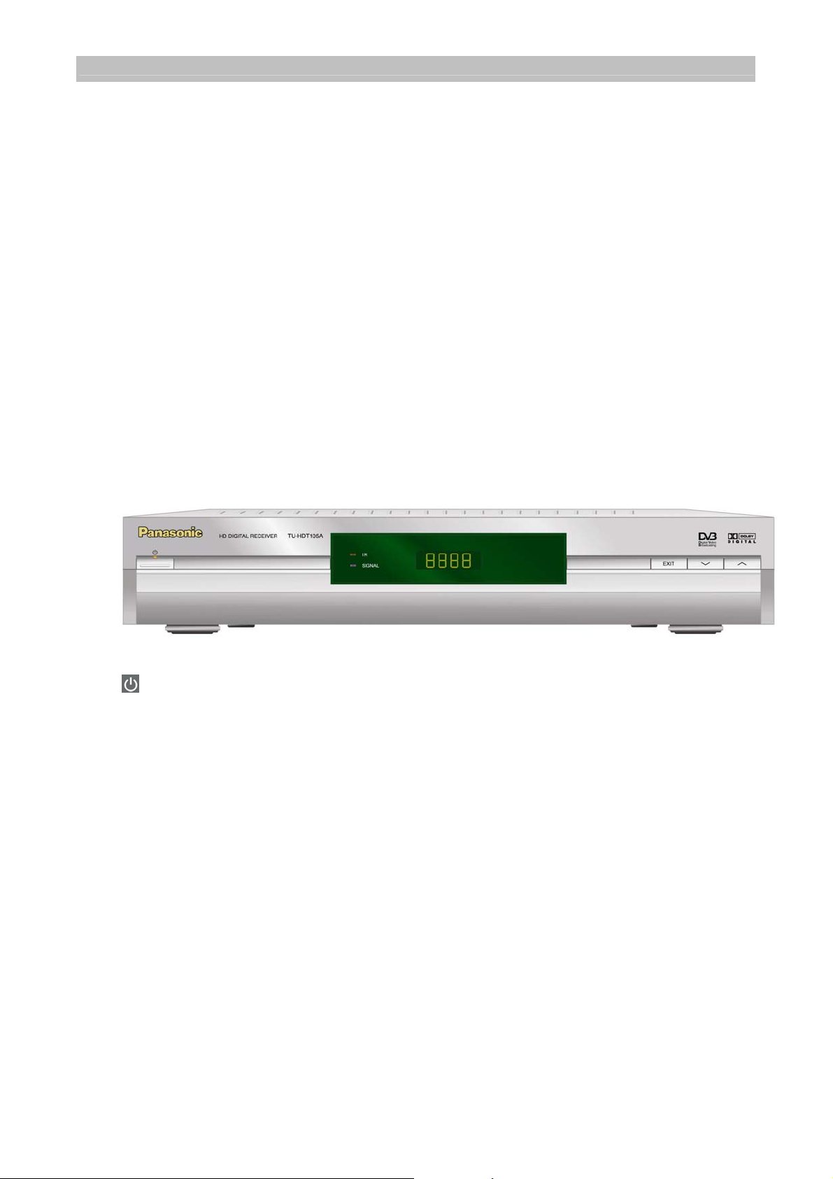
2.1
Front Panel
(Power Button): Turns the Digital Receiver On / Off (Standby mode).
EXIT Button: To return to the previous menu from the sub-menus.
Display: Shows channel number when the box is activated or current time (in the
Front Panel Arrow Buttons: S/T buttons to select channels or settings within the
Stand-By Indicator (LED): Lights red in Stand-By mode. When the Digital Receiver
Infrared (IR) Indicator (LED): The red LED flashes, indicating the box has received
Signal Indicator (LED): When a signal of a channel is successfully acquired the
form hhmm) when the box is in standby mode.
menus.
is working the LED becomes green.
a command from the remote control.
yellow LED will light up.
4
Page 5
Operating Instruction Book
TU-HDT105A
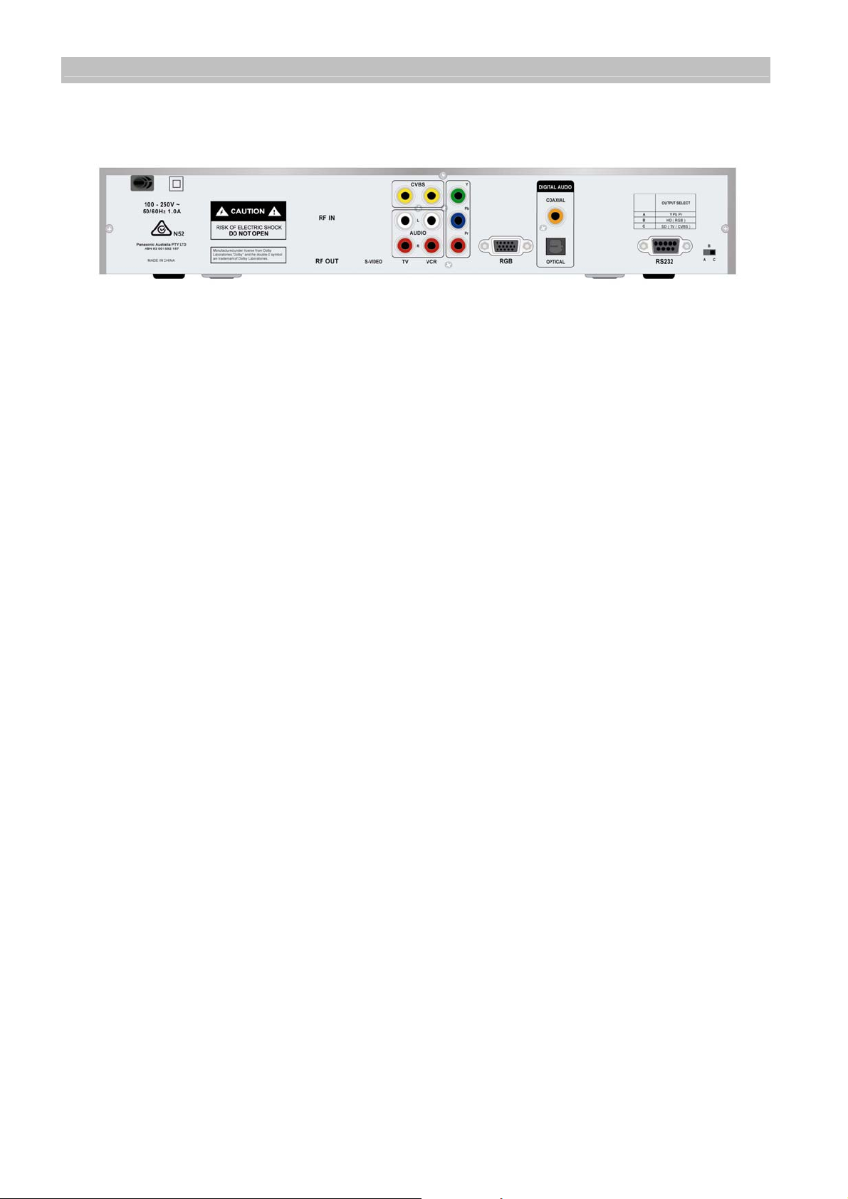
2.2 Rear Panel
AC Power Mains: (100 - 250V~; 50/60 Hz), 1.0 A.
RF In: For connection to cable from outdoor terrestrial antenna.
RF Out: For connection to your TV antenna IN or VCR RF IN.
S-Video: Y/C component video for connection to TV.
CVBS: Two composite video outputs for connection to TV, VCR or other A/V receiver
AUDIO: Two sets of stereo audio outputs for connection to TV, VCR or other A/V
receiver.
YPbPr: Y/Pb/Pr component video for connection to TV.
RGB: R/G/B/HS/VS component video for connection to TV or monitor.
Coaxial: Digital Audio output by coaxial.
Optical: Digital Audio output by optical.
Serial Port (RS232): For system maintenance.
A/B/C Switch: Switches for video output mode selection. Selection options are listed
in the table.
2.3 Box Contents
The box that carries your Digital Receiver should also contain the following items:
Remote Controller
Two batteries (AAA Size)
RCA video cables (one white / red, the other red / green / blue)
RF cable
User’s Manual and Warranty Card
3 The Remote Controller
3.1 Preparing the Remote Controller
Remove the cover of the battery compartment (on the back of the handset)
Insert 2 AAA (1.5V) batteries. While inserting, observe the + and – markings
indicated inside the battery compartment.
Replace the cover.
Test the remote controller by pressing any key and check if the IR-LED (Red) on the
front panel of the receiver flashes.
5
Page 6

Operating Instruction Book
TU-HDT105A
3.2 Remote Control Button Functions:
: To turn your STB on/off
(standby mode)
TV/RADIO: To toggle between
TV and Radio service
AUDIO: To select the desired
audio sound track
: Aspect ratio, to change to
16:9, 4:3 letterbox or 4:3
centre-cut mode
: : Mute function, to turn
on/off sound (only used
for analogue audio output)
: For Volume adjustment
(only used for analogue
audio output)
: For changing channels
LIST: To show channel list
STTL: To turn closed captions
on/off
: (Red): Application
defined function key
: (Green): Application
defined function key
: (Yellow): Application
defined function key
: (Blue): Application
defined function key
MENU: To display the “Main”
Onscreen Display
GUIDE/INDEX: To obtain a list
of programs on available
channels. This
information is only shown
if your broadcaster
transmits program
information; INDEX: To
go to index page in
Teletext mode
EXIT: To go back one level in
the menus.
: :
: To call up the program
information plate and
extended channel
information in program
guide menu. This
information is only
available if the
broadcaster or network
transmits the information.
:
show the hidden
information in the
Teletext mode.
buttons: To select menu
items in the menus.
buttons: To cycle through
options within the menus
OK: To confirm choices and
selection of highlighted
item
Number (0~9) keys: To select
channels directly and
other commands.
Broadcasters have
allocated logical channel
numbers (LCN) to their
services based on their
service number identity.
The programs can be
selected by the LCN.
1: TEN, 2: ABC, 3: SBS
5: TEN Regionals,
6: SEVEN Regionals,
7: SEVEN,
8: NINE Regionals,
9: NINE
TV/TEXT: To turn Teletext
on/off; TEXT: To toggle
between TV and Teletext
: To toggle
between present and
previous channels; HOLD:
To stop current page in
Teletext mode.
6
Page 7

Operating Instruction Book
TU-HDT105A
4 Installing Your Digital Receiver
4.1 Connecting Your Digital Receiver
The following illustrations show some examples for connecting this HD Digital
Receiver. Select the connection that is best suited for your needs. Many other
connections may be possible when optional devices such as RF cable splitters are
included in your system. These devices may cause signal degradation and, if too
many are used, poor quality picture and sound may result.
Terrestrial antenna/cable connection
Connect the TV antenna cable to the HD Digital
Receiver RF IN connector. Also connect the
cable between your TV Antenna IN and RF Out
connector on the rear of the Digital Receiver.
This connection allows your TV set to receive
normal analogue programs. (Refer to A)
Video Connections
(A) Aerial Connection
Adjust switch on the rear panel according to the format supported by your display
device, and it contains three modes: A, B and C.
Mode A (SD/HD, YPbPr)
Connect the YPbPr component video output
socket on your digital receiver to your display
device’s YPbPr component video input. Be sure
to match the colours on the RCA sockets with t
he
coloured plugs. (Refer to B)
Note: When unit is in Mode A, there is no video
output from the CVBS TV socket.
(B) YPbPr Connection
Mode B (HD, RGB)
Connect the D-sub socket to your display
device. (Refer to C)
Note: Cable is not supplied.
(C) RGB Connection
7
Page 8

Operating Instruction Book
TU-HDT105A
Mode C (SD, TV/CVBS)
Connect the CVBS composite video output
socket on your digital receiver to your TV’s
CVBS video input socket.
Connect the S-Video (Y/C) component video
output socket on your receiver to your TV’s SVideo input socket.(Refer to D)
Note: Cable is not supplied.
Note: When unit is in Mode C, there is no
output from the YPbPr sockets.
Audio Connections
(a) Digital Audio
If your display device is equipped with Dolby
Digital and/or MPEG audio decoding capability,
you may connect the Digital Audio output of
your digital receiver to the display device’s
Digital Audio input using either the Optical or
Coaxial RCA socket. (Refer to E) You may
also connect the digital audio output to your
A/V receiver if it is capable of decoding a
Dolby Digital / MPEG digital audio stream.
Note: Cable is not supplied.
(b) Analogue Audio
If your display device and/or A/V receiver does
not support Dolby Digital / MPEG decoding,
you will need to connect the L/R Audio output
RCA sockets on your digital receiver to the
stereo L/R Audio inputs of your display device
and/or A/V receiver.
(Refer to F). If your A/V receiver supports
Dolby Pro Logic decoder, you can switch ON
the “Stereo Surround” function (Page 20).
(D) CVBS / S-Video Connection
(E) Digital Audio Connection
(F) Analogue Audio Connection
8
Page 9

Operating Instruction Book
TU-HDT105A
4.2 Output Mode Selection
After you have connected the AV cables for video and audio between your digital
receiver and the display device, check that the position of the output selection switch
is correct for your chosen connection method as in the table below.
Switch Position Video Output Format Receiver Mode
A YPbPr (Component Video) SD / HD
B RGB HD
C CVBS / S-Video SD
Switch on the digital receiver and the display device, and select the correct AV input
on the display device. The digital receiver will take about 10 seconds to switch on.
You may now start the installation procedure.
The installation procedure is used to set up the video formats that may be output
from the digital receiver to the display device. During this procedure the digital
receiver may test if the display device is capable of correctly displaying 576i, 576p,
1152i, 1080i and 720p video formats. You will be asked to test these video formats
on the display device and confirm if the picture is displayed correctly. If the display
device is not capable of displaying a particular video format, the digital receiver will
return to the last correctly displayed format after about 12 seconds.
Note: In some cases, a display device will fail to return to a previously tested mode
after failing to display the next mode (i.e. the display does not support this format). If
you experience this, turn the display device off, wait 10 seconds and then turn the
display device on.
Installation Format Selection
Use the Remote Control keypad to perform the digital receiver format testing and
installation. Follow the digital receiver’s on-screen instructions to do the installation.
Mode A (SD/HD, YPbPr)
The switch on the rear of the digital receiver
must be in position A, and the AV connections
must be taken from the YPbPr RCA sockets.
You have selected YPbPr format
at the rear panel switch.
The digital receiver display will show “HdcI”.
Press OK to confirm the selection, or switch to
another mode. Proceed to INSTALLATION.
Press OK to continue.
Note: If the STB is connected to a HD only YPbPr input on the display, no picture will
be displayed until you have pressed the TV/TEXT to change to 576p format.
9
Page 10

Operating Instruction Book
TU-HDT105A
Mode B (HD, RGB)
The switch on the rear of the digital receiver
must be in position B, and the AV
connections must be taken from the RGB
HD15 socket. The digital receiver display
will show “Hd r”. Press OK to confirm the
selection, or switch to another mode.
You have selected HD(RGB) format
at the rear panel switch.
Press OK to continue.
Proceed to INSTALLATION.
Mode C (SD, CVBS)
The switch on the rear of the digital receiver
must be in position C, and the AV
connections must be taken from the CVBS
TV RCA socket. The digital receiver display
will show “Sdtv”. Press OK to confirm the
selection, or switch to another mode.
You have selected SD(TV/CVBS)
format at the rear panel switch.
Press OK to continue.
Proceed to INSTALLATION.
Installation
The on-screen display will ask which type of display
device is being used. You will have a choice of
either Plasma, LCD (Flat panel displays) or CRT
(eg Standard television).
Select from the choices using the remote control
keypad. The following screen will ask you to
Please select the display type:
1 Plasma Display
2 LCD TV
3 CRT TV
confirm 576i / 576p (depending upon the current
mode). Follow the on-screen instructions to test HD576p, HD1152i, HD1080i and
HD720p formats.
Note: Not all video formats are available in all modes. The following table describes
the available formats in each mode.
HD (YPbPr) HD (RGB) SD (CVBS)
LCD/Plasma CRT LCD/Plasma CRT LCD/Plasma CRT
576i X X X X
576p X X X X
1080i X X X X
1152i X X
720p X X
Table 1: Output format table
10
Page 11

Operating Instruction Book
TU-HDT105A
When all formats have been tested, a list of all accepted video formats will be
displayed. You will have the option to accept this list or to start the procedure again.
The accepted display formats are then
displayed and you are requested to s
your preferred display format, or to select
Dynamic Format Selection. When
Dynamic Format Selection is selected,
the digital receiver will choose the best
format for the received digital program.
The selected output format can be
changed at any stage in the Video menu
(section 6.3)
elect
Your display device supports the following formats:
576i
576p
1152i
1080i
720p
Press 1 to accept this list.
Press 2 to do testing again.
NOTE : Anytime you change the rear panel switch or change display device, you will
have to restart the procedure again.
4.3 State & Territory Selection
The first time the digital receiver is installed,
or after default settings are restored (section
6.5), please select the state or territory that
you live in. This will enable the digital
receiver to display the correct local time.
4.4 Power Saving Timer
This function requires a time to be set for the automatic shutdown of the digital
receiver. The receiver will automatic go into standby to save power. The time is set
from the last received command sent to the receiver. The default setting is 4 hours.
4.5 Auto Scan Channel
The first time the digital receiver is installed, or after default settings are restored
(section 6.5), the digital receiver will automatically scan for available digital services.
This will take around five minutes or so.
11
Page 12

Operating Instruction Book
TU-HDT105A
5 Operating Instructions: Knowing your basic controls
To become acquainted with the operations and functions of your receiver, you should
learn how to use the control buttons on the Front Panel and the Remote Control.
The following segment is an introduction to features that you will most commonly use.
5.1 Switching On Your Digital Receiver
Before you switch on your receiver please ensure the power lead is plugged into a
240V AC socket. Remember that as long as the digital receiver remains plugged into
a 240V supply, the receiver will be in constant “STANDBY”.
Switch on your receiver by pressing either the button on the remote control or the
button on the front panel. While the digital receiver is in normal viewing mode,
the green LED lights up. When not using the digital receiver, put your equipment in
the “STANDBY” mode by pressing either one of the / buttons again. When the
red “STANDBY” LED lights up, it indicates the digital receiver is in “STANDBY” mode.
The front panel will show current local time. When the digital receiver is in standby
mode, the power consumption is reduced by about 50%.
5.2 Information Plate
The Information Plate (I-Plate) shows information
about the program that you are currently watching.
The information plate appears briefly whenever you
switch to a new channel or when there’s a problem
with signal reception. To show the information plate,
press the
again will cause the program
synopsis to be revealed. Pressing
again will toggle the synopsis to the next program
information. To exit the synopsis, continue pressing
the button. Pressing the EXIT button will remove the I-Plate from the
screen at any time. The I Plate shows information about program, the time it is being
broadcast and the type of service.
Program Guide
The Program Guide is a user-friendly feature, which enables you to select, book, and
“peek in advance” at programs. To enter into the Program Guide, press
GUIDE/INDEX. In the Program Guide on-screen display, the program schedule is
listed in chronological order.
Section 6.1 of your User Manual will instruct you to use the Program Guide efficiently.
button. Pressing
12
Page 13

Operating Instruction Book
TU-HDT105A
5.3 Changing or Selecting Channels
There are several methods to change or select a channel. You can either use the
front panel or the remote control buttons.
The following methods are available for you to choose from:
Press Channel on the remote control (channel changes according to favourite
channel settings).
Directly enter a logical channel by using the number keys on the remote control.
Broadcasters have allocated logical channel numbers (LCN) to their services based
on their service number identity. The programs can be selected by the LCN.
1: TEN,
2: ABC,
3: SBS
5: TEN Regionals,
6: SEVEN Regionals,
7: SEVEN,
8: NINE Regionals,
9: NINE
Use to change channel. Unlike Channel control channel movement is not
aligned with favourite channels setting.
Use
channel.
5.4 Audio Mode Selection
Australian broadcasters transmit MPEG and/or
Dolby Digital audio with all programs. The audio
mode default setting is MPEG. This can be
changed by pressing the audio button AUDIO on
the remote control to change between the
available sound types. When you first press the
button, the Audio OSD is shown on screen l
all available soundtracks. The currently played
track is highlighted. This OSD will disappe
few seconds. Press the Audio key again to select
another track before this OSD disappears.
to toggle between current channel and previously watched
isting
ar in a
13
Page 14

Operating Instruction Book
TU-HDT105A
5.5 Display Aspect Selection
During the installation, the digital receiver aspect
ratio is automatically set to widescreen 16:9 when
a HD format or SD component video is selected a
s
the output format. With a SD output format, the
aspect ratio is set to 4:3.
The aspect ratio can be changed, in SD, between
widescreen 16:9, centre cut for 4:3, or letterbox.
The Display Aspect can be changed using the
remote control by pressing the aspect button
to bring up the OSD. The OSD will have one
aspect selection highlighted. To change the
display aspect, push the button until you have the desired picture aspect. The
OSD will disappear after a few seconds. This function is similar to the VCR out
setting on page 19. However the “Display Aspect” setting affects the TV CVBS or
YPbPr output, while the “VCR out” setting affects only the VCR CVBS output.
6 Using the Main Menu
Your receiver comes with a directory of features or the Main OSD. The Main is your
gateway to customising many of the features offered by your receiver. To access the
Main OSD, press the MENU button. The Main feature comprises the following
categories of services:
Program Guide provides access to:
Programs Schedule
Programs Categorisation
Booked Programs
TV/Radio Channels provides access to:
Program Favourite Channels
Selection of Favourite Channels
Channel locking
Video Menu provides access to:
Video Output Format
Teletext Contrast
Banner Display Time Out
VCR Screen Format
14
Page 15

Operating Instruction Book
Audio Menu provides access to:
Audio Delay Time
MPEG Audio Level
Audio Mode Priority
Digital Audio
Stereo Surround
Audio Balance
Tuning Menu provides access to:
Channel Installation
Region Select
Power Saving Timer
Password Change
Parental Guidance
Restore Default Settings
Diagnostic Information displays the Software
Version number, serial ID of your receiver, and
display the signal strength and quality.
6.1 Program Guide
Programs Schedule
By choosing the Program Guide banner on the
Main OSD, the Electronic Program Guide (EPG)
appears. The EPG is, in classic terms, a TV
Guide, except it is presented on your TV s
The EPG allows you to peek in advance
creen.
,
depending on services provided by the
broadcaster, a few days or up to one week of
TV programs and program information. By
using the arrow keys on either your receiver or
the remote control, you can roam the EPG to
access various channels and programs.
In the list, highlight the desired program by
pressing the arrow buttons. Once you have selected your choice (the highlighted
block will appear in a different colour), the detailed description of the program can be
read on the right. If the broadcaster has not transmitted detailed description for the
program, the text “No description available” will appear. If you wish to see what
programs are being broadcast on other channels, use the channel up or down button
to access the list of all programs shown for the current and next days (subject to
availability).
TU-HDT105A
15
Page 16

Operating Instruction Book
TU-HDT105A
If you wish to book a future program, highlight any
program (beyond the current time frame) by using
the arrow buttons, and press OK to confirm your
selection. The “Booking” window will appear
allowing you to book the program. Press OK to
confirm the booking, or EXIT to exit the Booking
window. For more information on the Booking
feature, see “Booked Programs” on page 16.
Note that if you highlight a program currently being
broadcast on another channel and press OK, th
e
program is not booked. Instead, the receiver
switches to that channel directly.
Coloured “Hot Keys”
On the Program Guide window, you will notice four coloured hot keys. They provide
you instant access to various services.
Category Selection
This special feature enables you to screen out your
preferred programs by program Category or type.
You can gain access to this feature by pressing the
yellow button. Use the arrow buttons
to highlight the
categories, and press OK to select or unselect any of
the categories. By default, the item “All Categories”
is highlighted. You have to de-select that item before
selecting specific program type(s). As you select
some categories and go back to program guide menu,
only programs of the selected categories will be
visible.
Booked Programs
To review what programs are currently booked, press
the blue button to call up the Booked Programs OSD.
To cancel or re-engage the booking, press OK. If the
alarm clock symbol ( ) disappears, then the timer is
disengaged. The program information will remain in
case you wish to rebook the program. The cancelled
program will not be displayed the next time this
window reappears.
16
Page 17

Operating Instruction Book
TU-HDT105A
6.2 TV/Radio Channels
You may highlight any channel in the list by pressing up/down keys, then press OK to
view that channel directly.
Favourites Selection
This feature allows you to personalise your list of
favourite channels, TV or Radio. Highlight a channel
by using the
select or unselect. When a channel is selected a
“﹀” symbol will appear in the bar to indicate the
favourite status. When you are changing channels
using the keys, the receiver jumps to the
next/previous favourite channel, and skips other
channels.
If you wish to lock or unlock any channel, simply
press the green button to do so. When a channel is
locked a symbol will appear to indicate the locked
status. Whenever you wish to watch the locked
channel you will be asked to enter the password.
To toggle between the TV ( TV ) and Radio ( ) lists, press the TV button.
6.3 Video Menu
Instructions on how to set each item are presented
on the next page.
buttons, then press the red key to
favourite
lock/unlock
select all
de-select all
17
Page 18

Operating Instruction Book
TU-HDT105A
Video Output Format
After the initial format setting procedure, the o
format still can be changed according to your
preference. The formats you are allowed to select
depend on the initial format checking process
is, only the formats that your display device
supports.
Teletext Contrast
The contrast of teletext pages can be adjusted to
suit your display by selecting from the 3 available
settings.
Banner Display Time Out
This feature allows you to use
Plate). The delay time depends on your choice, such as 4 seconds, 6 seconds, 8
seconds, and 16 seconds.
VCR Screen Format
This setting affects the video format at the VCR output.
If your display is 4:3 format, and the transmission of a
program happens to be 16:9, the Letterbox mode will give
you a complete picture, but black areas will appear at the
top and bottom.
Alternatively you can choose the Centre Cut mode to play
the program in a full-screen format. However information
on the left and right sides may be cut off.
If your display is 16:9 format, then set the mode to
Widescreen 16:9. If a program happens to be in 4:3,
black areas will appear at the left and right of the s
in order to present the picture in a correct aspect r
to display time out for the Information Plate (I-
utput
, that
Letterbox
Centre Cut
creen
atio.
16:9 Wide
Panasoni c
18
Page 19

Operating Instruction Book
Operating Instruction Book
TU-HDT105A
TU-HDT105A
Power Saving Timer
This function requires a time to be set for the automatic shutdown of the digital
receiver. The receiver will automatic go into standby to save power. The time is set
from the last received command sent to the receiver. The default setting is 4 hours.
6.4 Audio Menu
From here, you may adjust various settings according to your personal preference.
Note that some settings in this segment are related to the A/V equipment to which the
digital receiver is connected.
Audio Delay Time
Different displays may have different delay in
displaying pictures, which may cause a slight
problem with lip sync. This feature allows you to
use
to select your choice according to your
actual video display equipment, in order to
compensate for this delay. The delay time
depends on which choice appears to provide best
performance of lip sync on your display device.
MPEG Audio Level
From here you my adjust MPEG audio level from –12 db to 0 db. This adjustment is
only for MPEG input and system will detect MPEG input automatically.
19
19
Page 20

Operating Instruction Book
TU-HDT105A
Audio Mode Priority
The Audio mode allows you to adjust the audio setting. You may choose Dolby
Digital (Dolby D), MPEG1 and MPEG2. Use
to select your choice. Like the
Audio Language Priority setting, this audio mode setting determines your initial
choice of soundtrack based on the audio mode, and you may select any soundtrack
channel by channel, regardless of the audio mode setting made in this menu.
If the default Audio Mode is Dolby D, and the input signal contains only MPEG2, the
default Mode wi
ll change to MPEG2 automatically. If the Audio Mode is set to Dolby
D, the digital receiver will automatically select a Dolby D soundtrack when it is
available.
selection if you will be connecting your receiver to a
We especially recommend this
TV or A/V receiver that can decode Dolby Digital (look logo) or Dolby
Surround Pro Logic (look for the ogo).
l
for the
Digita
l Audio
igital Audio Selection Options.
For each Audio Mode, you can have different D
(Refer to Table 2, Digital Audio Selection Table)
Table 2: Digital Audio Selection Table
Default Audio Mode
Dolby Digital
Digital Audio Selection Options
Bitstre
PCM
am
(stereo)
3. Off
MPEG-2 Same as above
MPEG-1
o *Bitstream: select this if your TV or A / V receiver has a digital audio input and can decode
Dolby Digital
o *PCM (stereo): select this if your TV or A / V receiver has a digital audio input but can not
decode Dolby Digital
o *Off: select this if you want the digital audio output to mute when a Dolby Dig
being received.
PCM (stereo)
2. Off
ital program is
Stereo Surround
You can toggle Stereo Surround on or off by pressing and OK.
On: Surround information will be included in stereo output (Lt/Rt)
Off: Pure stereo audio output (L/R)
Audio Balance
You can adjust the value from L+7 to R+7. The selection “0” means balanced (equal
level) output on the two front speakers.
20
Page 21

Operating Instruction Book
TU-HDT105A
6.5 Tuning Menu (Defau
lt password: 0000)
The Tuning Menu Settings are used to program your digital receiver. Again, som
the settings, especially “Channel Installation” (1), may require assistance from the
Panasonic Customer Care Centre (132600). Your digital receiver will ask you to
in a password, and the default password is 0000.
Channel Installation
When the receiver is initially set up, conduct a
channel search by selecting the “Auto Channel
Search” func
tion.
Auto
Channel Search
Auto Channel Search provides the easiest way to
conduct a channel search. It does not require you to
ente strongly
r any other information. This function is
reco sers. However, t
mmended for regular u he user
should be aware that all existing channels w
remo s you confirm start of aut
ved as soon a o scan.
ill be
In the Auto Channel Search OSD, all channe
will be listed. The channel search may take
minu
tes.
ls found
a few
If you exit an auto scan during the scan process, some ch
avail l
ab e to you.
annels may not be
Manual Channel Search
In the “Manual Channel Search” window you can set
the specific channel to search. Press the left or right
button then OK to select the broadcast RF channel
you wish to search.
Note: The RF channel is not the sam
e as the service
station name number.
e of
key
21
Page 22

Operating Instruction Book
TU-HDT105A
Region Select
Using
you may select your local region: New
South Wales, Victoria, South Australia,
Queensland, Western Australia, Tasmania,
Northern Territory, and Australian Capital
Territory. This setting will a
llow the digital
receiver to display the current time in the I-Plate
or when the receiver is in Stand-By mode.
Password Change
From here you can change the password. Once
the new password is set DO NOT FORGET IT!
If you change the passw
ord, we strongly
suggest that you write down the new password
in
the □□□□ area. Without the password,
you cannot access any functions that require
you to provide the correct password! If you
forget your password, please contact customer
service for help.
Parental Guidance
Using
Block All, Block G
digital receiver will aut
the age limit you have set.
program has rating equal to
you may select to block programs with a certain rating or above: N
, Block PG, Block M, Block MA, Block AV, and Block R. Your
omatically block programs that are unsuitable to children under
For example, if you choose “Block PG” and a received
or above PG, the digital receiver will ask the viewer to
one,
enter the password before viewing that program.
on to activate this function.
However, not all transmissions carry ratings informati
22
Page 23

Restore Default
Setting
If you wish to reset all previous settings, you can
use this feature to do so. Once you decide to
restore default settings, all previous sett
ings will
be lost. Please be very careful before you
confirm this action.
.6 Diagnostic Information
6
From here, you can get g
eneral information
about the Serial ID, software and hardware
version on which it is operating, and display
signal strength and quality.
The signal strength and signal quality are shown
as separate bars. For the digital receiver to
function correctly, both these bars need to be
displayed in green colour. If either of the bars
is
displayed in the orange colour, there may be
video and audio reception problems (see
Troubleshooting)
. If either of the bars is
displayed in red colour, there is a problem with
the reception of the digital signal and the antenna and c
receiver need to be checked by a qualified antenna installer
on page 27.
6.7 Teletext Operation
Teletext is only available on certain broadcast
channels. The time taken to display the pages
and sub-pages is set by the teletext transmitter.
Teletext is also used for Closed Captioning of
television programmes for the hearing impaired.
Closed captions can be found on Teletext Page
801. The picture remains on the screen while
you ty
Some broadcast stations will have a message
on the screen to tell you that closed captions
are not available for this programme. Some
broadcast stations give you no indication at all.
pe in 801.
Operating Instruction Book
TU-HDT105A
onnection to the digital
. See Troubleshooting
23
Page 24

Operating Instruction Book
TU-HDT105A
TOP (Table Of Pages) MO
DE
In TOPTEXT mode, the red button moves to the previous page number and the green
button moves to the next page number. The ye
different subjects. Pushing the coloured butto
current preferred method of operation in Australia
llow and blue buttons correspond to
n can access these subjects. This is the
.
Red /Green / Yellow / Blue buttons
In TOP TEXT mode these correspond to the differently coloured subjects.
TV / Teletext mode
Press the TEXT button. The screen will display the Teletext page. Press again when
you wish to return to TV mo
de.
Note:
If you press the TEXT button while
teletext, there may not be any indication on t
viewing a station that is not transmitting
he screen. Press the TEXT button to return
to normal viewing.
Page Selection
Pages can be selected in two ways:
a. Press the Up / Down buttons to increase o
b. By entering the page number, using 0 - 9 on t
r decrease the page number by one.
he remote control.
Hold
Hold is used to hold the Teletext page when
viewing multi-page information. Press
again to return to automatic page update.
Index
Press INDEX to return to the main index page. Depending on the way information is
transmitted, this may hav
e to be pressed more than once to return to the main index
page.
Reveal
To reveal hidden words e.g. quiz page answers
. Press again to hide.
24
Page 25

Operating Instruction Book
TU-HDT105A
Sub Coded Page Access
When Teletext information exceeds more than one page, it may take some time for the
automatic changing of the sub pages to reach the sub page you require. As each sub
page is found its number is displayed at the bottom of the page so that you may select it
by pressing left or right cursor key. As more sub pa
ottom of the page changes, so that you are always offered the most recently
b
ansmitted selection of sub pages.
tr
ges are picked up, the display at the
hile selecting dynamic mode , sub page
W
ill be changed dynamically and it will depend
w
on which page now i
s available. And you can
fix on specific sub page by pressing HOLD
key, while in dynamic mode.
ccess to specific sub page by pressing left /
a
You can also
right cursor key to select the sub page
number.
Closed Captions
he broadcasters sometimes transmit program with subtitles for the hard of hearing.
T
hese closed captions are accessed by the remote control STTL button.
T
25
Page 26

7
Glossary
A/V: A connector for the
transmission of audio, video and
status signal.
Information Plate: A small
window with simple navigation
tools to display information about
individual channels.
Menu: An onscreen display
offering a list of commands to
select from.
Normal viewing: The state of
your receiver when no menus or
windows are displayed on the
screen
, and a valid channel is
tuned.
Parental Lock: A feature
enabling parents to “lock”
programs that they consider
unsuitable for children’s viewing.
A “locked” program can only be
“unlocked” with the Password.
Password: A personal 4-digit
number for controlling specific
features of the digital receiver
including access to locked
channels. Also
known as the PIN
Number.
Operating Instruction Book
TU-HDT105A
Program Guide: The
instantaneously and continuously
updated electronic program
guide for quick and easy
reference or program selection.
Reminder: Message displayed
on the screen informing viewers
that a booked program is about
to start.
Integrated Receiver Decoder
(IRD): A device that is capable of
decoding and tuning digital
signals and converting these
signals into a format that is
understood by your TV set. Aside
from decoding signals, it also
verifies access rights.
Standby mode: A condition in
which your receiver allows
retrieval of up-dated information
from input signals.
VCR: Abbreviation for Video
Cassette Recorder.
26
Page 27

oting 8 Troublesho
Problem What to do Possible causes
Operating Instruction Book
TU-HDT105A
ay on the panel
does not
No sound erly
The remo
wor .
Una ed in or
Small “blo
squares”
appear on re, or
the ur
The digita
not receiv
channels
light up.
or picture. The A/V cord is not prop
king
ble to tune channels. TV antenna is not plugg
ck type
sometimes
the pictu
pict e freezes.
l receiver does
e all the local TV
.
Power Mains cable is nThe displ
connected.
connected.
Wrong selection of out
Batterte control is not
y exhausted. C
Fluorescent light interferin
remote control.
Remote control is incorrectly aimed A ote control at the receiver.
digital TV is not availab
area.
See “DTV Reception Tro
Shooting Guide” below.
The signal strength of so
RF channels may be to
See “DTV Reception Tr
Shooting Guide” be
ot
put mode.
le in this
uble
me of the
o low.
ouble
low.
g with the S
C
heck that the mains cable is plugged in to
th
e power socket.
heck the cable connections and other
C
quipment connected to your receiver.
e
T
ry another output switch position.
hange the batteries.
witch off the light.
im the rem
C
heck the antenna cable connections or if an
u
pgrade to your antenna is required to
re
ceive digital TV signals in this area.
‘signal quality’ or ‘signal strength’ bar is not
If
reen, it indicates that the digital receiver is
g
ot receiving an adequate signal. The
n
ntenna and/or cable system needs to be
a
hecked (maybe replaced) by an antenna
c
staller.
in
heck that the antenna is sui
C table to receive
ainll RF channels. Try doing channel tuning
stallation again.
What to
do if you can’t solve the problem
If you h a ove without solving the problem, please
contact re on for additional help.
ave tried all of the actions suggested
the Panasonic Customer Care Cent
b
132 600
DTV Reception Trouble Shooting Guide
After a channel scan, some channels or no channels are found
Your TV antenna may not be properly connected to your digital receiver
1. Did you connect your antenna as illustrated in the quick connect guide?
If you have a pay TV box or a VCR connected then the HD-STB must be the first
device connected to the antenna. (That is the antenna should be plugged into the
STB and the STB RF-Out should then be plugged into the next device.
2. Is the antenna wall socket in good condition?
For optimum and reliable contact performance, the antenna wall connector should be
an ‘F’ (screw) type connector.
3. Are you using a quality antenna fly lead between antenna wall socket and HD-STB?
The use of RG6 or RG59 Quad Shield 75 ohm coaxial cable fly leads with metal ‘F’
connectors provides a secure, reliable connection that also greatly reduces impulse
noise pickup. Low cost antenna fly leads with right-angled plastic moulded
connectors are a common cause of poor reception and impulse noise pickup.
27
Page 28

Operating Instruction Book
TU-HDT105A
Digital TV or some channels (services) may not have yet commenced in your area.
There are nd regions in Au
some towns and regio
can check the d
some towns a stralia that cannot yet receive digital television. In
ns ave comm
not all broadcasters h
igital cov your area at the Rece the DBA website
erage for
enced their digital services. You
ption Locator on
(www.dba.org.au/reception).
Signal Strength
The signal received m or to allow the digital receiver to find some or all
ay be too po
available channels.
Your old antenna may n l DT
ot be designed to receive al V channels.
Antenna reception
connections / cabling
perfo due t
rmance has deteriorated o weathering, corrosion of antenna
and broken elements.
If you live within 5-10Km of DTV transmission towers, a
combined VHF/UHF antenna
should be adequate. Outside this area, separate VHF and UHF antennas provide superior
reception performance.
Depending on DTV sign stallations may instead require a VHF/UHF
al conditions, some in
masthead amplifier.
a shared antenna system the existing Master Antenna TV (MATV) system may have
In
been originally designed for analogue PAL TV only, and may require a substantial upgrade
or replacement to also carry DTV signals. Please consult your Body Corporate
.
or your safety any external aerial should be installed by a reputable qualified installer and
F
should comply with Australian Standard AS1
417.1.
ome channels display ‘No Signal’ or ‘Loss of Signal’
S
eceived signal is “too weak” (i.e.; poor quality) to generate a stable picture
R
Please check antenna & cabling or contact your local TV antenna installer.
icture regularly breaks up on some channels
P
The received signal may be too weak to allow the digital TV receiver to reliably “lock” to the
desir picture.
ed signal and generate a stable
Please check antenna & cabling or contact your local TV antenna installer.
28
Page 29

Operating Instruction Book
TU-HDT105A
Impulse Noise
terference from household appliances such as lights, refrigerators, washing machines,
In
electric stoves etc may cause pictures to break up and audio to mute or distort
momentarily
In the first instance, replace a
hm coaxial cable fly lead. If problem persists, check / improve antenna & cabling or
o
ontact your local TV antenna installer. The possible cause could be poor quality coaxial
c
cable installed in t
be replaced with quad shield.
to
he walls or ceiling picking up impulse noise. This coaxial cable will need
ntenna fly-lead with a quality RG6 or RG59 Quad Shield 75
A masthead amplifie
TV tuner, resulting in poor reception on some or all channels.
D
r may be “over-boosting” the antenna signal, which is overloading the
lease contact your local TV antenna installer.
P
icture very infrequently breaks up on some or all channels
P
Electrical atmospheric interference caused by local or distant lighting storms or heavy rain
with wind in “leafy” locati
omentarily.
m
ons may cause pictures to break up and audio to mute or distort
Impulse noise interfe
ehicle or lawn mower with a “noisy” ignition system
v
rence from an infrequently used electrical appliance, or a passing
29
Page 30

Operating Instruction Book
TU-HDT105A
Technical Specifications 9
Features Specifications Parameters
Terrestrial
Tuner/Demodulato
Video Decoder
(SD/HD) -2 MP@ML and MP@HL
r
Input frequency VHF, UHF Band
Standard DVB-T (ETS 300 744)
Channel Bandwidth 7MHz, Australian Channel
COFDM System
Demodulation type QPSK, 16QAM, 64QAM
Guard Interval 1/32, 1/16, 1/8, 1/4 active symbol duration
FEC
CPU 32-bit RISC System
Transport DVB De-multiplexer
Standard
Field / Frame rate 50 / 25 Hz
HD/SD decoding capability,
interlaced/progressive mode
Aspect ratio
Output modes
2k, 8k carrier
Hierarchical supported
1/2, 2/3, 3/4, 5/6, 7/8
ISO/IEC 11172-2 MPEG-1
ISO/IEC 13818-2 MPEG
1080i, 720p, 576p and 576i
4:3 and 16:9
Letter Box supported
Native HD mode:
1080i(1125) / 720p / 576p
CRT HD mode:
1080i(1250) / 1080i letterboxed in 1152i / 576p
SD mode:
576i
Output format changed by specific hot-key
(software switchable)
Caption / Teletext
Audio Decoder
Software Upgrade
Rear panel interface
Decoding and display of Activated
by specific hot-key
Closed Captions
Decoding and display of
Activated by specific hot-key
Teletext (ETS 300 706, Level
1.5, TOP)
ISO/IEC 11172-3 MPEG-1 layer I and layer II
Standard
Sampling rate 32, 44.1, 48 and 96 kHz
Digital Audio SPDIF Output
format
Support Over Air Download and
Download through RS-232 port
RF input connector IEC type, Female, 75 Ohm
Loop through Output connector IEC type, Male, 75 Ohm
Selection switch for HDTV /
SDTV
CVBS composite SD video
Outputs and
Stereo Audio Outputs
Y/C SD video output S-VHS
Y/Pb/Pr component video Output 3 RCA connectors
R/G/B/HS/VS DB-15 (Female)
Digital Audio SPDIF Coaxial / Optical
Serial port RS-232 (Female, DB-9)
ISO/IEC 13818-3 MPEG-2 Layer II
Dolby Digital
IEC-60958 for PCM data
IEC-61937 for encoded Audio Data
HD (YPbPr) / HD (RGB) / SD
1 RCA connector for TV video with OSD
2 RCA connectors for TV audio, adjustable
volume
1 RCA connector for VCR w/o OSD
2 RCA connectors for VCR audio. fixed volume
30
Page 31

User interface
Power requirements
Environmental Condition
Dimension
Accessory
EMC / Safety
Copyrig Quanta Network c. All Rights Reserved.
Customer’s Record
The serial number of this produc
and on the carton. It is recomm ed that you note the serial
number and other details in the
booklet in a safe place as a perm our purchase to
aid ntification in the even theft or loss.
in ide t of
No.
Model
Serial No.
Purcha
P sed From
urcha
Operating Instruction Book
4 Keypads, 7-segment display and 3 LED
Front panel
Mains input voltage 100-250VAC~
Mains input frequency 50/60 Hz
Power consumpti
Temperature
Relative Humidity out condensation)
Dimension 365 x 245 x 60 mm
Weight 2.45kg
Remote Controller
Battery
User’s manual
A/V Cable
RF Cable 1.8m, 3C2V, IEC Male/Fem
Standard
on
indicators
IR Sensor
Normal operation
Standby mode: 8
32~108°F (0~40°C)
20~80% (With
AAA 1.5V x 2
1.8m, R/G/B for component video
AS/NZS CISPR 13:2003 Class B
AS/NZS 60
: 22Watt.
Watt
udio 1.8m, R/W for stereo a
ale
065: 2000
ht © 2005 Systems In
t can be found on its rear cover
end
space provided and retain this
anent record of y
se Date
TU-HDT105A
31
Page 32

WARRANT
1. The product is warranted for 12 months from the date of purchase. Subject to the conditions
of this warran Authorised rm necessary service on
the product without charge for parts or lab f Panasonic, the product is
found to be f und to be fau ranty period.
2. This warrant o products or its Authorised
Distributors o nd only where the p nd serviced within Australia or
it’s territories. ty cover only applies ce carried out by a Panasonic Authorised
Service Cent id proof of purchase is presented when warranty service is
requested.
3. This warranty f the product has been installed and used in accordance with the
manufacturer’s recommendations (as noted under normal use
and reasonab the opinion of Pana ers normal office use on
office related nd normal domesti not rentals use) and
do er dama
es not cov ge, malfunction or incorrect voltages,
accident, mis ct, build-up of dirt or stment of customer controls,
main supply problems, thunderstorm activity, infestation by insects or vermin, tampering or
repai abnormally
r by unauthorised persons (including unauthorised alterations), exposure to
corro
sive conditions or any foreign object or matter having entered the product.
4. If warranty service is required you should:
- omer Care Centre on 132600 for the name/address of the
Telephone Panasonic’s Cust
nearest Authorised Service C
- Provide a copy of your purchase receipt as proof of date of purchase.
- ote that
Send or bring the product to a Panasonic Authorised Service Centre. Please n
freight to and / or from your nearest Authorised Service Centre must be arranged b
5. The elivery,
Panas ropolitan areas and most regional
centres of Australia, however, coverage will vary dependant on product. For advice on exact
Autho ed Service Centre locations for your product, please telephone our Customer Care
Centre on 132600.
Unless otherwise specified to the consumer the benefits conferred by this express warranty are
additio itions, warranties, guarantees, rights and remedies expressed or
implied by the Trade Practices Act 1974 and similar consumer protection provisions contained in
legisla s ries and all other obligations and liabilities on the part of the
manuf turer or supplier and nothing contained herein shall restrict or modify such rights,
remed i s.
warranties hereby conferred do not extend to any costs associated with the d
han d
dling, freighting, or transportation of the product or any part thereof or replacement of an
do
not extend to any damage or loss occurring during, or associated with, transit.
onic Authorised Service Centres are located in major met
ris
nal to all other cond
tion of the State and Territo
ac
ies, obligations and liab litie
THIS RANTY AND THE PURCHASE DOCKET (OR SIMILAR PROOF OF PURCHASE)
WAR
Y
ty Panasonic or its Service Centre will p
r if, in the opinion o
ou
o lty within the war
y only applies t sold by Panasonic Australia
r Dealers a roducts are used a
Warran to servi
re and only if val
only applies i
in the operating instructions)
le care (in sonic). This warranty cov
products a c use on other products (but
failure resulting from use of
use, negle
SHOULD BE RE
entre.
TAINED BY THE CUSTOMER AT ALL TIMES
dust, abuse, maladju
erfo
y you.
 Loading...