

Page 1

HDTV Digital Receiver
Operating Instructions
TU-HDS20
For assistance, please call: 1-800-211-PANA (7262) or
send e-mail to: consumerproducts@panasonic.com
TQB2AA0344 00125
PRINTED IN USA
Page 2

Table of Contents
Safety Instructions............................................ 2
Important Information ....................................... 4
Information on Digital Television..................... 6
Digital Television.........................................................................6
Digital Broadcasting and Cable TV.............................................6
Digital Audio................................................................................6
Information on the HDTV Digital Receiver ....... 7
Reception Capability of HDTV Digital Receiver......................... 7
Panasonic HDTV Digital Receiver Model TU-HDS20.................8
Congratulations..................................................9
Customer Record........................................................................9
Care and Cleaning ......................................................................9
Specifications..............................................................................9
Important Notes................................................10
HDTV Digital Receiver Location...............................................10
Connecting Cables...................................................................10
AC Power Supply Cord............................................................10
Satellite Dish Antenna Connection...........................................10
Antenna Installation and Orientation........................................10
Antenna/Cable Connection ......................................................11
TU-HDS20 Front Panel.....................................12
TU-HDS20 Rear Panel ......................................13
HD Digital TV Display Formats........................14
HD Digital TV video Formats.....................................................14
Display Format Selection ..........................................................14
Aspect Ratio Selection..............................................................16
Channel and Program Tuning ATSC Reception ......................18
Channel Banner ........................................................................19
Viewing modes..........................................................................22
Dolby Digital (AC-3) Audio ........................................................25
Getting Started..................................................27
Step 1. Connect AC Power Cord..............................................27
Step 1a. Antenna / Cable Connection.......................................27
Step 1b. DIRECTV Satellite Dish Connection...........................27
Step 2. Connection to DTV-Compatible TV..............................28
Step 2a. Connection to RGB Monitor........................................29
Step 2b. Connection to Conventional TV..................................30
Step 3. Digital Tv Reception with DTV-Compatible TV
(no Satellite or Cable Service) ........................................... 31
Step 3a. Digital Tv Reception with Conventional TV
(no Satellite or Cable Service) ..............................................32
Step 3b. Digital TV Reception with DTV-Compatible TV
(Cable Service and Terrestrial Antenna).............................33
Step 3c. Digital TV Reception with Conventional TV
(Cable Service and Terrestrial Antenna)............................ 34
Step 3d. Digital 8VSB Cable / Analog Cable Reception
with DTV-Compatible TV....................................................35
Step 3e. Digital 8VSB Cable / Analog Cable Reception
with Conventional TV..........................................................36
Step 4. Turning HDTV Digital Receiver ON.............................37
Step 5. Switching to DTV Mode............................................... 37
Step 6. Roller Guide Menu™...................................................37
Step 6a. ACTION/Navigation Button........................................38
Step 7. Antenna/Cable Mode...................................................38
Step 8. HDTV Digital Receiver Connection to
VCR/S-VIDEO VCR.............................................................39
Step 9. Programming Available Channels................................40
TABLE OF CONTENTS
Optional Connections.......................................41
HDTV Digital Receiver Connection to Dolby Digital
AC-3 Decoder ..........................................................................41
Remote Control Guide......................................42
Remote Control Functional Key Chart......................................43
Battery Installations and Precautions....................................... 45
Special Remote Buttons...........................................................46
Programming the Remote Control............................................49
Remote Control Component Codes.........................................50
Special Features of the HDTV
Digital Receiver...............................................54
Impulse Pay per View...............................................................54
Impulse Pay per View Icons.....................................................55
Software Upgrade Messages...................................................57
Roller Guide Menu™.........................................58
Navigation/ACTION button.......................................................59
Roller Guide Menu Feature Chart....................60
SETUP.....................................................................63
Satellite Setup..........................................................................63
Guide Setup..............................................................................67
Antenna Setup..........................................................................68
Monitor......................................................................................71
System Test..............................................................................72
Access Card.............................................................................73
ADVANCED PROGRAM GUIDE............................74
Direct Channel Entry ................................................................75
Banner Description Icons.........................................................76
Guide Banner Categories.........................................................77
Grid...........................................................................................78
LOCK ......................................................................79
Password..................................................................................79
Movies Limits............................................................................80
TV Limits...................................................................................81
Channel Lock............................................................................82
Spending..................................................................................84
ACCOUNT...............................................................85
Future Purchases.....................................................................85
Past Purchases........................................................................86
OPTIONS ................................................................87
Audio ........................................................................................87
Caption.....................................................................................88
Clock.........................................................................................89
Satellite/Local Tuning Mode.....................................................90
About........................................................................................91
TIMER .....................................................................92
Timer error Messages..............................................................93
Glossary and Acronyms...................................94
Troubleshooting Table .....................................96
Read these instructions completely before
operating.
Specifications are subject to change without notice
or obligation.
Copyright 2000 by Matsushita Electric Corporation of America.
All rights reserved. Unauthorized copying and distribution is a
violation of law.
1
Page 3

SAFETY INSTRUCTIONS
RISK OF ELECTRIC SHOCK
DO NOT OPEN
WARNING: To reduce the risk of electric shock do not remove cover or back. No
user-serviceable parts inside. Refer servicing to qualified service personnel.
The lightning flash with arrow
head within a triangle is intended
to tell the user that parts inside
the product are a risk of electric
shock to persons.
Note To CATV System Installer: This reminder is provided to call the CATV system installer's attention to article 820-40 of
the National Electric Code that provides guidelines for proper grounding and, in particular, specifies that the cable ground shall be
connected to the grounding system of the building, as close to the point of cable entry as practical.
Note To Satellite Dish Installer:
This reminder is provided to call your attention to Article 810 and in particular article 810-15 of the National Electrical Code which
covers proper installation and grounding of television receiving equipment as well as to article 820-40 of the National Electrical Code
which specifies that the satellite dish cable ground shall connected to the grounding system of the building as close to the point of
cable entry as practical.
Safety Instructions For The HDTV Digital Receiver:
1. Read and apply the operating instructions provided with HDTV Digital Receiver.
2. Read all of the instructions given here and retain them for later use.
3. Unplug this HDTV Digital Receiver from the wall outlet before cleaning. Do not use liquid or aerosol cleaners. Use a damp
cloth for cleaning.
4. Do not use attachments not recommended by the HDTV Digital Receiver manufacturer as they may cause hazards.
5. Do not use this HDTV Digital Receiver near water. For example: Avoid placing it near a bathtub, washbowl, kitchen sink, or
laundry tub, in a wet basement, or near a swimming pool, etc.
6. Do not place this HDTV Digital Receiver on an unstable cart, stand, or table. The HDTV Digital Receiver may fall, causing
serious injury to a child or adult and serious damage to the appliance. Use only with a cart or stand recommended by the
manufacturer, or sold with the HDTV Digital Receiver. Wall or shelf mounting should follow the manufacturer's instructions, and
should use a mounting kit approved by the manufacturer.
6a. An appliance and cart combination should be moved with care. Quick stops, excessive force, and uneven
surfaces may cause the appliance and cart combination to overturn.
7. Slots and openings in the cabinet and the back or bottom are provided for ventilation, and to insure reliable
operation of the HDTV Digital Receiver and to protect it from overheating. These openings must not be blocked
or covered. The openings should never be blocked by placing the HDTV Digital Receiver on a bed, sofa, rug or
other similar surface. This HDTV Digital Receiver should never be placed near or over a radiator or heat register. This HDTV
Digital Receiver should not be placed in a built-in installation such as a bookcase unless proper ventilation is provided.
8. Operate only from the type of power source indicated on the marking label. If you are not sure of the type of power supplied to
your home consult your HD Video dealer or local power company. For Digital Receivers designed to operate from battery
power, refer to the operating instructions.
9. This HDTV Digital Receiver is equipped with a polarized alternating-current line plug (a plug having one blade wider than the
other). This plug will fit into the power outlet only one way. This is a safety feature. If you are unable to insert the plug fully into
the outlet, try reversing the plug. If the plug should still fail to fit, contact your electrician to replace your obsolete outlet. Do not
defeat the safe purpose of the polarized plug,
10. Do not allow anything to rest on the power cord. Do not locate this HDTV Digital Receiver where the cord will be abused by
persons walking on it.
11. Follow all warnings and instructions marked on the HDTV Digital Receiver.
12. Do not overload wall outlets and extension cords as this can result in fire or electric shock.
2
The exclamation point within a triangle is
intended to tell the user that important
operating and servicing instructions are
in the papers with the appliance.
Page 4

SAFETY INSTRUCTIONS
13. Never push objects of any kind in to this HDTV Digital Receiver through cabinet slots as they may touch dangerous voltage
points or short out parts that could result in a fire or electric shock. Never spill liquid of any kind on the HDTV Digital Receiver.
14. If an outside antenna is connected to the decoder equipment, be sure the antenna system is grounded so as to provide some
protection against voltage surges and built up static charges. In the U.S. Section 810 of the National Electrical Code, ANSI/
NFPA 70 provides information with respect to proper grounding of the mast and supporting structure, grounding of the lead-in
wire to an antenna discharge unit, size of grounding conductors, location of antenna-discharge unit, connection to grounding
electrodes, and requirements for the grounding electrode. See Figure.
15. For added protection for this HDTV Digital Receiver during a lightning storm, or when it is left unattended and unused for long
periods of time, unplug it from the wall outlet and disconnect the antenna. This will prevent damage to the decoder due to
lightning and power-line surges.
16. An outside antenna system should not be located in the vicinity of overhead power lines or other electric light or power circuits,
or where it can fall into such power lines or circuits. When installing an outside antenna system extreme care should betaken to
keep from touching such power lines or circuits as contact with them might be fatal.
17. Unplug this HDTV Digital Receiver from the wall outlet, and refer servicing to qualified service personnel under the following
conditions:
a. When the power cord or plug is damaged or frayed.
b. If liquid has been spilled into the HDTV Digital Receiver.
c. If the Digital Television Decoder has been exposed to rain or water.
d. If the HDTV Digital Receiver does not operate normally by following the operating instructions. Adjust only those controls
that are covered by the operating instructions as improper adjustment of other controls may result in damage and will
often require extensive work by a qualified technician to restore the HDTV Digital Receiver to normal operation.
e. If the HDTV Digital Receiver has been dropped or the cabinet has been damaged.
f. When the HDTV Digital Receiver exhibits a distinct change in performance - this indicates a need for service.
18. Do not attempt to service this Digital Television Decoder yourself as opening or removing covers may expose you to dangerous
voltage or other hazards. Refer all servicing to qualified service personnel.
19. When replacement parts are required, be sure the service technician has used replacement parts specified by the manufacturer
that have the same characteristics as the original part. Unauthorized substitutions may result in fire, electric shock, or other
hazards.
20. Upon completion of any service or repairs to this HDTV Digital Receiver, ask the service technician to perform routine safety
checks to determine that the decoder is in safe operating condition.
21. WARNING: TO PREVENT FIRE OR SHOCK HAZARD, DO NOT EXPOSE THIS APPLIANCE TO RAIN OR MOISTURE.
22. CAUTION: TO PREVENT ELECTRIC SHOCK DO NOT USE THIS (POLARIZED) PLUG WITH A RECEPTACLE OR OTHER
OUTLET UNLESS THE BLADES CAN BE FULLY INSERTED TO PREVENT BLADE EXPOSURE.
Note: DIRECTV service can only be received within the USA and is not available in Canada
3
Page 5

IMPORTANT INFORMATION
Important Information
FCC INFORMATION
Your HDTV Digital Receiver is registered with the Federal Communication Commission and is in compliance with CFR47, Parts 15 and 68, FCC Rules and Regulations.
Radio Interference
This equipment has been tested and found to comply with the limit for a Class B Digital Device in accordance
with the specifications in Part 15 of FCC Rules. The rules are designed to provide reasonable protection against
radio and television interference in a residential installation. This equipment generates, uses and can radiate
radio frequency energy and, if not installed and used in accordance with the instructions, may cause harmful
interference to radio communications. However, there is no guarantee that interference will not occur in a particular installation.
If this equipment does cause interference to radio or televisions reception (which you can determine by turning
the equipment off and on), try to correct the interference by one or more of the following measures.
• Reposition or relocate the receiving antenna for the radio or television that is “receiving” the interference.
• Change the position of the HDTV Digital receiver with respect to the radio or television equipment that is
receiving interference.
• Move the HDTV Digital receiver away from equipment receiving interference.
• Plug the HDTV Digital receiver into a different wall outlet so the HDTV Digital receiver and equipment
receiving the interference are on different branch circuits.
If these measures do not eliminate interference, please consult your dealer or an experienced radio/television technician for assistance.
FCC CAUTION:
Pursuant to 47CFR, Part 15.21 of the FCC rules, any changes or
modifications to this HDTV Digital Receiver not expressly approved by
Matsushita Electric Corporation of America could cause harmful
interference and would void the user’s authority to operate this device.
To assure continued compliance, the modem cable (Part #TSX2AX002)
provided with the HDTV Digital Receiver must be used when connecting
the unit to the phone line.
FCC Declaration of Conformity
PANASONIC CONSUMER ELECTRONICS COMPANY
Responsible party:
Matsushita Electric Corporation of America
One Panasonic Way
Secaucus, NJ 07094
U.S.A.
Telephone Number: 1-888-726-2377
(8 a.m.-10 p.m., Mon-Fri, EST)
(10 a.m.-10 p.m., Sat-Sun, EST) OR
E-MAIL: CONSUMER PRODUCTS@PANASONIC.COM
This device complies with Part 15 of the FCC rules. Operation is
subject to the following two conditions: (1) this device may not
cause harmful interference, and (2) this device must accept any
interference received, including interference that may cause
undesired operation.
4
Page 6

IMPORTANT INFORMATION
Notification to the Local Telephone Company.
On the bottom of this equipment is a label indicating among other information, the FCC Registration number and Ringer Equivalence Number (REN) for the equipment. You must, upon request, provide this information to your telephone company. The REN is useful to determine the number of devices you may
connect to your telephone line and still have all these devices ring when your telephone number is called.
In most (but not all) areas, the sum of the RENs of all devices connected to one line should not exceed five
(5.0). To be certain of the number of devices you may connect to your line as determined by the REN, you
should contact your local telephone company.
If trouble is experienced with this equipment (HDTV Digital Receiver), for repair or warranty information,
please contact the service center in the U.S.A. at the phone number listed on page 97. If the equipment is
causing harm to the telephone network, the telephone company may request that you disconnect the
equipment until the problem is resolved.
Notes: This equipment may not be used on coin service provided by the telephone company.
Party lines are subject to state tariffs, and therefore, you may not be able to use your own telephone equipment if you are on a party line. Check with your local telephone company.
Notice must be given to the telephone company upon permanent disconnection of your HDTV Digital
Receiver from your line.
Rights of the Telephone Company.
Should your equipment cause trouble on your line which may harm the telephone network, the telephone
company shall, where practicable, notify you that temporary discontinuance of service may be required.
Where prior notice is not practicable and the circumstances warrant such action, the telephone company
may temporarily discontinue service immediately. In case of such temporary discontinuance, the telephone
company must: (1) promptly notify you of such temporary discontinuance (2) afford you the opportunity to
correct the situation and (3) inform you of your right to bring a complaint to the Commission pursuant to
procedures set forth in Subpart E of Part 68, FCC Rules and Regulations. The telephone company may
make changes in its communication facilities, equipment, operations of procedures where such action is
required in the operation of its business and not inconsistent with FCC Rules and Regulations. Of these
changes are expected to affect the use or performance of your telephone equipment, the telephone company must give you adequate notice, in writing, to allow you to maintain uninterrupted service.
5
Page 7

INFORMATION ON DIGITAL TELEVISION
Information on Digital Television
Digital Television
HDTV (High Definition Television)
HDTV signal formats are 1080i (interlaced scan) and 720p (progressive scan). HDTV
provides the highest resolution picture and audio in either stereo or 5.1 channel
surround sound.
SDTV (Standard Definition Television)
SDTV signal formats are 480p and 480i. SDTV provides lower resolution, yet presents
a very sharp clear picture. Lower resolution allows broadcasters to transmit multiple
programs per channel.
Digital Broadcasting and Cable TV
The FCC has not mandated any standards for cable operators at the time this manual
is printed. Some cable companies have announced plans to introduce digital cable
boxes into their markets. They may choose, however, to use the digital capability to
increase the number of channels available or to provide data capability, such as high
speed modem rather than transmit HDTV programming. Contact your local cable
provider to determine if digital cable is available and whether a cable box is needed for
converting the signals.
Digital Audio
Dolby* Digital surround sound (also commonly referred to as AC-3* or DD 5.1) is the
audio standard. AC-3 will provide digital-quality sound. The system provides 3
separate audio channels for the front speakers (left, center, right), 2 channels for the
rear surround sound speakers, plus one channel for subwoofer sound. You will need
an external audio system capable of decoding the AC-3 encoded sound to get the full
surround sound effect. Otherwise, it can be connected directly to your TV or audio
system using only the stereo (left/right) audio outputs.
Note: The stereo audio outputs are Dolby Surround compatible. You can connect a Dolby
Surround Pro Logic* decoder (not included) to the stereo audio outputs and receive
surround sound.
*Manufactured under license from Dolby Laboratories. “Dolby“, “AC-3”, “Pro Logic” and the double-D
symbol are trademarks of Dolby Laboratories.
6
Page 8
INFORMATION ON THE HDTV DIGITAL RECEIVER
Information on the HDTV Digital Receiver
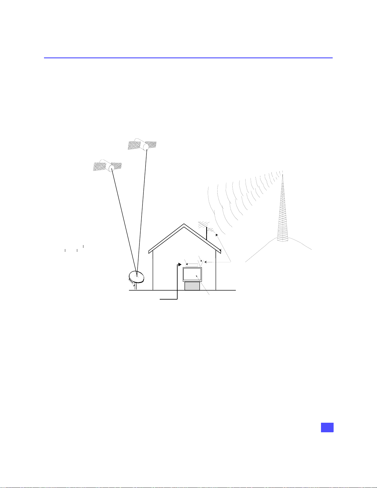
Reception capability of HDTV Digital Receiver
The Panasonic HDTV Digital Receiver is capable of receiving analog (NTSC) and
digital (ATSC format), cable (NTSC and ATSC formats), and digital satellite (coming
from DIRECTV if you subscribe to DIRECTV
availability of digital terrestrial broadcast, your HDTV Digital Receiver can make
receiving all types of signals seamless. The following drawing shows how you can
receive various types of signals.
DIRECTV
SATELLITE
DIRECTV
SATELLI TE
ANALOG/DIGI TAL
TERRESTRIAL
ANTENNA
®
programming*) programming. With
TOWER SENDING
TERRESTRIAL/DIGI TAL
SIGNALS
SATELLITE
DISH ANTENNA
CABLE SIGNAL
HD RECEIVER
TERRESTRIAL
ANTENNA
TV, HDTV, OR HD MONITOR
*Terrestrial off-air signals or unscrambled cable-service signals can be received by
the HDTV Digital Receiver.
Note: The shape of your satellite dish antenna determines what type of signal that
your antenna can receive. If you have an oval shaped dish, you can receive
signals from DIRECTV Satellites, including HD programming.
Note: Due to copyright restrictions, you may not be able to view some high definition
programs in high definition format using this product.
7
Page 9

INFORMATION ON THE HDTV DIGITAL RECEIVER
Panasonic HDTV Digital Receiver Model TU-HDS20
Panasonic HD ATSC/NTSC HDTV Digital Receiver with a built-in DIRECTV PLUS™
receiver, can receive and process DIRECTV standard definition video and DIRECTV
high definition video from satellite broadcasts if you subscribe to
DIRECTV®*programming. It can also receive and process NTSC local terrestrial and
cable analog programming and ATSC compliant terrestrial and cable digital
programming. This HDTV Digital Receiver can output both Digital (Y,PB,PR or RGB)
or composite signals. This digital receiver will output NTSC composite video when
480i video output is selected.
Current Conventional Televisions
Model TU-HDS20 uses specially developed chips which allow current televisions (with
A/V inputs) to display digitally broadcast programs. The HDTV Digital Receiver, which
receives digital signals, has the ability to convert the digital broadcast into National
Television System Committee (NTSC)** signals (480i) that a conventional television
can display. Most conventional televisions will not be able to display HDTV programs
in their original format.
DTV-Compatible Televisions
The HDTV Digital Receiver, by using component video or RGB connections, will allow
DTV-compatible televisions to produce pictures with incredible resolution.
Component video consists of three (3) primary color signals: red, green and blue that
together convey all necessary picture information. The three (3) component signals
have been translated into luminance (Y) and two color difference signals (PB, PR),
each on a separate wire. The HDTV Digital Receiver, depending on the capabilities of
the DTV-compatible television, will give you the choice of HDTV or SDTV video
output.
HDTV-Compatible (1080i / 720p)
HDTV-compatible TV models process and display high definition output from the
Panasonic HDTV Digital Receiver in a 1080i or 720p video format.
SDTV-Compatible (480p / 480i)
SDTV-compatible TV models process and display standard definition output from the
Panasonic HDTV Digital Receiver in a 480p or 480i video format.
*DIRECTV, the Cyclone Design logo, and DIRECTV PLUS are trademarks of DIRECTV, Inc., a unit of
**NTSC is the current television system used in the U.S. It uses analog (non-digital) signals.
Hughes Electronics Corp., and are used with permission.
8
Page 10

Congratulations
Your Panasonic HDTV Digital Receiver features state-of-the-art technology for high-quality
picture and sound with complete audio/video output jacks for your home theater system.
This HDTV Digital Receiver is capable of receiving DIRECTV® high definition satellite
signals. DTV signals are displayed in either an interlaced or progressive format, providing a
clear, crisp picture. This HDTV Digital Receiver also has a separate ATSC/NTSC tuner to
provide additional digital and analog signal capability. Your new HDTV Digital Receiver is
designed to give you many years of enjoyment.
Customer Record
The model and serial number of this product are located on the back of the Digital
Receiver. You should note the model and serial number in the space provided and
retain as a permanent record of your purchase. This will aid in identification in the
event of theft or loss. Product registration is available on-line at:
www.prodreg.com\panasonic.
Care and Cleaning
Turn HDTV Digital Receiver Off
r For HDTV Digital Receiver, avoid excessive moisture and wipe dry.
r Avoid bumping or scraping the HDTV Digital Receiver.
Remote Control
r For Remote Control, use a soft cloth dampened with water or a mild detergent
r Do not use benzene, thinner or other petroleum based products.
Specifications
Model
Number
TU - HDS20
Serial
Number
solution. Avoid excessive moisture and wipe dry.
CONGRATULATIONS
Power Source 120V AC, 60Hz
Channel Capability – NTSC and DTV
Satellite Signal Range
Digital Audio Output PCM/AC-3 Fiber Optic
Video Output Jacks
S-Video Output jack S-Video (Y-C) Connector
Audio Output Jacks 0-2.0V rms 4.7k Ohm
NTSC Video Output jack
NTSC Audio Output jacks 0-2.0V rms 4.7k Ohm
DTV Output (Y, PB, PR)/RGB Output
Modem Jack RJ11C, 4 Conductor
Specifications are subject to change without notice or obligation.
*The digital tuning system allows channel numbers up to 999 to be displayed. The total channel capability,
however, remains as stated.
VHF/UHF - 2-69*
CATV - 1-125*
950 - 1450 Mhz (L-Band)
1V
, 75 Ohm, Phono Jack Type
p-p
1V
, 75 Ohm, Phono Jack Type
p-p
75 Ohm, Phono Jack Type
9
Page 11

IMPORTANT NOTES
Important Notes
HDTV Digital Receiver Location
This unit can be used as part of an entertainment center. Consult your dealer for
available options.
r Avoid excessive sunlight or bright lights.
r Keep away from excessive heat or moisture. Inadequate ventilation may cause internal
component failure.
r Fluorescent lighting may reduce Remote Control transmitting range.
Connecting Cables
Component video cables (Y, PB, PR), audio cables and modem cable are provided for
connection to a DTV-compatible monitor/receiver. Shielded video cables (not
provided) should be used for all other connections between components. For best
results:
r Use 75 Ohm coaxial shielded cables.
r Check type of output and input connectors on your components.
r Determine required cable lengths.
AC Power Supply Cord
CAUTION: TO PREVENT ELECTRIC SHOCK, MATCH WIDE BLADE
OF PLUG TO WIDE SLOT OF AC OUTLET AND FULLY INSERT. DO
NOT USE A PLUG WITH A RECEPTACLE OR OTHER OUTLET
UNLESS THE BLADE CAN BE FULLY INSERTED TO PREVENT
BLADE EXPOSURE.
Polarized Plug
Satellite Dish Antenna Connection
Connect the cable coming from the DIRECTV PLUS™ satellite dish to the Satellite In
jack on the HDTV Digital Receiver.
Note: The shape of your satellite dish antenna determines what type of programming that
your antenna can receive. If you have an oval shaped dish, you can receive
programming from DIRECTV Satellites plus some local channels in certain areas.
Note: Consult your dealer on Satellite dish installation and options.
Antenna Installation and Orientation
In many areas, an indoor antenna can be used to received DTV signals. Certain conditions,
however, may create a situation where an outdoor antenna is required. Tall buildings, large
metal objects (e.g., a water tower) or hills may block the line-of-sight to the TV station and
interfere with DTV signal reception. Keep the following in mind when installing and orienting
your outdoor antenna. For additional information about antennas, see the Consumer
Electronics Manufacturing Association (CEMA) website at www.AntennaWeb.org or ask
your local dealer.
Yagi
10
r Choose an antenna with directional receiving characteristics such as a Yagi, log periodic,
or reflector antenna. Avoid loop, wire bowtie, rabbit-ear and omni-directional antennas.
Page 12

H Use good grade 75 Ohm coax (round) cable to connect the antenna to the HDTV Digital
Receiver. Do not use 300 Ohm flat twin-lead cable.
H Place the antenna away from large metal objects. If using an indoor antenna, remember
that aluminum siding and foil-covered insulation can greatly reduce the signal strength
inside your house.
H Point the antenna in the direction of the TV station. Allow a 4-6 second delay in tuning.
Log Periodic
Watch for a program to appear on the TV. If the signal indicator is “NOT FOUND” or if a
program comes and goes, try a slightly different position for the antenna. Slowly raising or
lowering the antenna by a few feet may help.
H Avoid standing in front of the antenna while adjusting its position. Move a few feet to the
rear to avoid changing the signal characteristics.
H If you are located in an area serviced by two (2) different DTV stations in different
directions, you may need an antenna rotator to receive signals from both stations.
Reflector
Antenna/Cable Connection
Antenna Connection
For proper reception of VHF/UHF channels, a directional antenna is required (see
previous page). For best reception, an outdoor antenna is recommended.
Procedure
H Connect the antenna cable from your antenna.
H Select ANTENNA, in the Roller Guide Menu™* SET UP Menu under Input (see Getting
Started section, Step 6).
Incoming Cable from
Home Antenna
IMPORTANT NOTES
75 Ohm ANT IN input on back
of HDTV Digital Receiver
Cable Connection
Before connecting your cable to the HDTV Digital Receiver, contact your local cable
provider and ask the following question:
• Do you need a separate cable box to receive cable channels in your area?
Note: The Panasonic HDTV Digital Receiver is able to receive DTV signals from your local
cable provider only if they are transmitted in the 8VSB modulation format approved by
the FCC for DTV transmission. Also, your cable provider may elect to transmit in the
8VSB format for only a limited period of time.
Procedure
H Connect the cable wire provided by your local cable provider.
H Select one of the following in the Roller Guide Menu™ SET UP Menu under Ant/Cable
Input (see Getting Started section, Step 7).
Incoming Cable from
Cable Provider
* Roller Guide Menu is a trademark of Panasonic Consumer Electronics Company. U.S. Patent Pending.
75 Ohm ANT IN input
on back of Digital
Receiver
11
Page 13

FRONT AND REAR VIEW OF THE HDTV DIGITAL RECEIVER
Front and Rear View of the HDTV Digital Receiver
Front Panel
Power Button
ATSC
CERTIFIED
DIGITAL TELEVISION
POWER
VIDEO OUT
Power indicator (LED)
Messages indicator
(LED)
Video out indicator (LED)
MENU, GUIDE, INFO
buttons.
NAVIGATION buttons
NATIVE HYBRID
1080i 720p
480p 480i
Video Out Button
Panasonic
HDTV DIGITAL RECEIVER
ATSC/NTSC/SATELLITE
Smart card
(behind door)
ACTION button
MENU
GUIDE
INFO
ACTION
Navigation buttons
MESSAGES
DOLBY
D I G I T A L
POWER Turns the HDTV Digital Receiver On.
VIDEO OUT Press to select Video Output mode.
SMART CARD Also known as Access Card, identifies you to your program
providers. DIRECTV PLUS™ System requires a valid card.
MENU Press to enter and exit Roller Guide Menu system.
GUIDE Press to access Advanced Program Guide.
INFO Press to display channel banner.
12
ACTION Press to enter selection from the Guide or from the Menu.
NAVIGATION
BUTTONS Press the navigation arrows to move the highlight up, down, left
or right.
MESSAGES Message indicator LED.
Page 14

Rear Panel
FRONT AND REAR VIEW OF THE HDTV DIGITAL RECEIVER
SATELLITE IN jack RF Out jack
SATELLITE
ANT IN
IN
MODEL NO.
SERIAL NO.
AC 120V 60 Hz
MAX AMPS
MANUFACTURED
CH 3
CH 4
CH3/CH4 Switch
RF OUT
RGB/YPBP
R
R-AUDI O-L
H-SYNC-L
DIGITAL OUTPUT
ANT IN jack
RGB/YPBPR Switch
ANT IN Use to connect an off-air antenna or cable TV signal to the
SATELLITE IN Use to connect DIRECTV satellite signal to the HDTV Digital
RF OUT Use to connect the HDTV Digital Receiver to your TV.
CH3/CH4 Switch If a coaxial cable is used to connect the digital receiver to
YP
RGB/YP
/ RGB Jacks Primary jacks used to connect the HDTV Digital Receiver to a
BPR
Switch Selects either RGB or Component video (Y,PB,PR) signals
BPR
DIGITAL OUTPUTS Outputs either Component Video or RGB signal .
NTSC OUTPUTS Use to connect the HDTV Digital Receiver to a Conventional
P
RPB
R
R-AUDI O-L VIDEO
H, V jacks
DIGITAL OUTPUTS
Y
BG
S-VI DEO
NTSC OUTPUT
HDTV DIGITAL RECEIVER
WARNING
RISK OF ELECTRIC SHOCK
DIGITAL
AUDIO OUT
(AC-3)
AC-3 / PCM Output
DO NOT OPEN
TEL LINE
NTSC OUTPUTS
®
!
ASSEMBLED IN MEXICO
Modem jack
DISTRIBUTED BY
MATSUSHITA ELECTRIC
CORPORATION OF AMERICA
ONE PANASONIC WAY,
SECAUCUS, NEW JERSEY 07094
jack
HDTV Digital receiver.
Receiver.
your TV, you must set the CH3/CH4 switch to either CH3 or
CH4.
DTV Compatible Television.
according to your TV/Monitor.
TV.
H, V jacks Horizontal and Vertical sync jacks used with RGB for high-
end monitors, video projectors etc..
AC 3/PCM OUTPUT Use to connect your HDTV Digital Receiver to a Dolby Digital
AC-3 receiver or decoder.
MODEM Use to connect a phone line to the HDTV Digital Receiver to
enable DIRECTV pay per view services.
13
Page 15
HD DIGITAL TV DISPLAY FORMATS
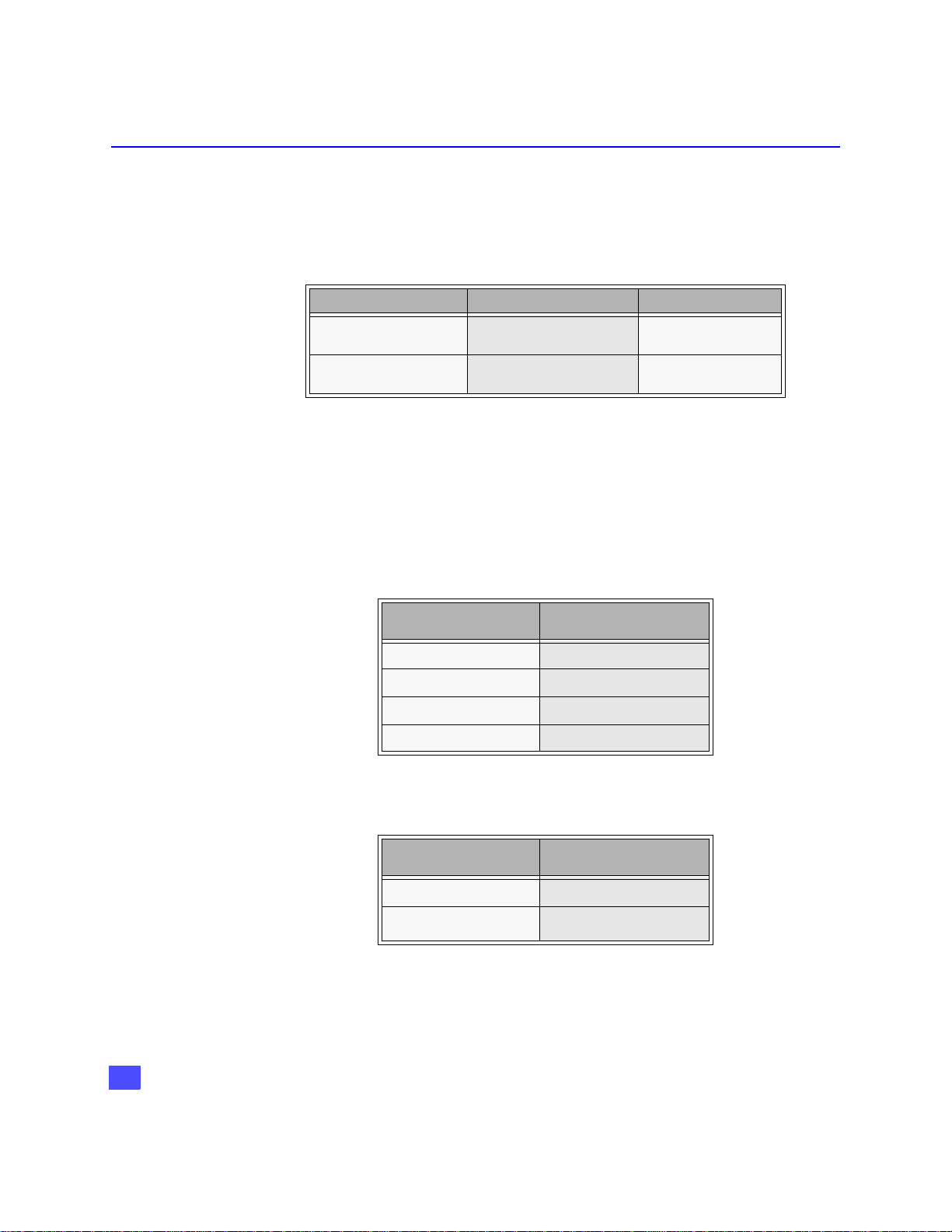
HD Digital TV Display Formats
The HDTV Digital Receiver converts all ATSC signal formats and HD DIRECTV signal
into viewable programming. The formats are variations on the four (4) formats, 1080i,
720p, 480p and 480i. The following table shows the display formats, resolutions and
aspect ratios.
DTV Format Resolution Aspect Ratio
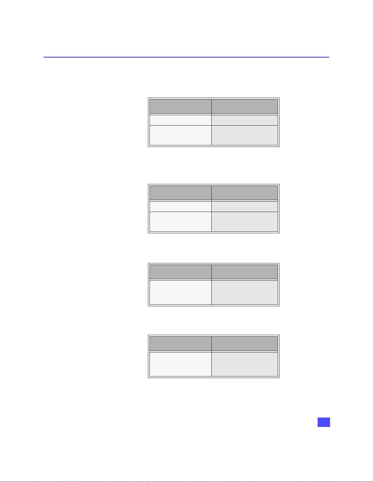
Display Format Selection
The HDTV Digital Receiver allows you to choose a display format based on the
capability of your TV or monitor. To select the appropriate display format, use the
VIDEO OUT button on the front panel of the HDTV Digital Receiver.
Note: This section applies to DTV-compatible televisions only.
NATIVE Format
If your TV is capable of displaying all four (4) formats, 1080i, 720p, 480p and 480i,
then select NATIVE mode using the VIDEO OUT button.
1080i
720p
480p
480i
High Definition 16:9
Standard Definition 16:9 or 4:3
Input Format Output Format
1080i 1080i
720p 720p
480p 480p
480i 480i
(to TV)
14
HYBRID Format
In the HYBRID format all 1080i and 720p signals are output as 1080i and 480i is
outputted as 480p.
Input Format Output Format
1080i
720p
480p
480i
(to TV)
1080i
480p
Page 16
HD DIGITAL TV DISPLAY FORMATS
1080i Format
If your TV is capable of displaying 1080i, then select 1080i by using the VIDEO OUT
button on the front of the HDTV Digital Receiver.
Input Format Output Format
1080i 1080i
720p
480p
480i
(to TV)
1080i
720p Format
If your TV is capable of displaying 720p. then select 720p by using the VIDEO OUT
button on the front of the HDTV Digital Receiver.
Input Format Output Format
1080i 720p
720p
480p
480i
(to TV)
720p
480p Format
If your TV is capable of displaying 480p format only, then select 480p by using the
VIDEO OUT button on the front of the HDTV Digital Receiver.
Input Format Output Format
(to TV)
1080i
720p
480p
480i
480p
480i Format
If your TV is capable of displaying NTSC format only, then select 480i by using the
VIDEO OUT button on the front of the HDTV Digital Receiver.
Input Format Output Format
1080i
720p
480p
480i
Note: In order to use either RF OUT or NTSC output jacks for NTSC video, the 480i Format
mode must be selected.
(to TV)
480i
15
Page 17
HD DIGITAL TV DISPLAY FORMATS
Aspect Ratio Selection
The HDTV Digital Receiver allows you to select an aspect ratio (picture display shape)
to match the source signal and shape of your TV screen. You can also change the
aspect ratio for your personal viewing preference. To select an aspect ratio, press the
ASPECT button on your remote control and the HDTV Digital Receiver will cycle to
the next available aspect ratio choice. The following table shows the available aspect
ratios.
Source Signal 16:9 4:3
16:9 Full (No Scaling) Full - Zoom - Letterbox
4:3 Full - Sidebar Full (No Scaling)
Full Aspect
16:9 or 4:3 picture will be displayed in the center of the viewing screen at full screen
width and height.
Zoom Aspect (4:3 Monitor receiving 16:9 source signal)
The picture will be expanded uniformly (width and height) to fill the viewing screen.
The picture will be cropped, either horizontally or vertically to fit the viewing screen.
The cropped portion of the original picture will be lost from view.
Note: To properly view Closed Captioning, the HDTV Digital Receiver may, in some cases,
change the aspect ratio from Zoom to Full.
Letterbox Aspect
Video formats with aspect ratios greater than 16:9 will be displayed at the proper
width, so no video information is lost. Bars will appear above and below the picture.
Monitor Format
16
Sidebar Aspect
4:3 pictures will be viewed on a wide aspect TV screen with vertical bars on both sides
of the picture.
Note: See following page for illustrations of the various aspect ratios.
Page 18
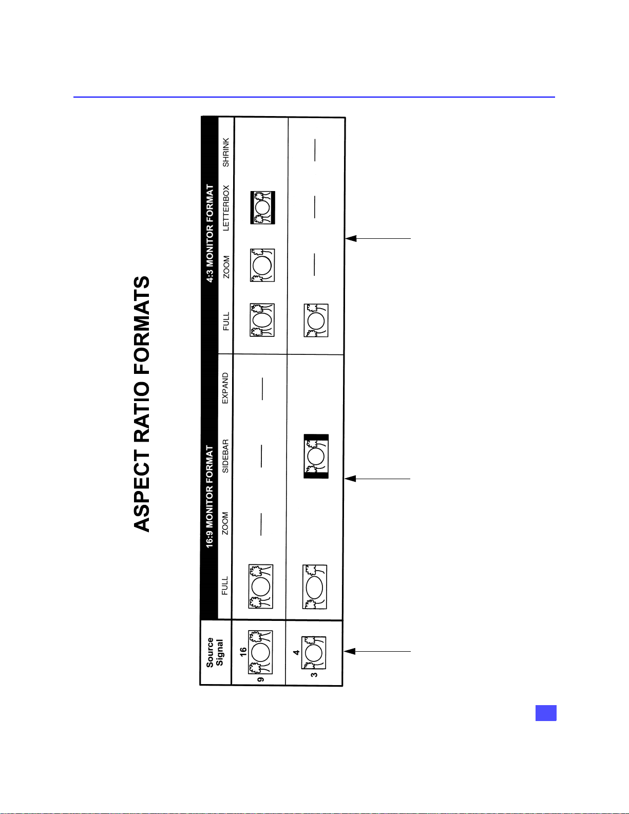
HD DIGITAL TV DISPLAY FORMATS
formats available when the HDTV Digital
Receiver receives a 16:9 source signal.
format available when the HDTV Digital
Receiver receives a 4:3 source signal.
These pictures show the different aspect ratios
available with a 4:3 monitor format.
• The top pictures show the 4:3 monitor
• The bottom picture shows the 4:3 monitor
These pictures show the different aspect ratios
available with a 16:9 monitor format.
• The top picture shows the 16:9 monitor
The 16:9 and 4:3 pictures
represent the incoming
source signals received by
format available when the HDTV Digital
the HDTV Digital Receiver.
Receiver receives a 16:9 source signal.
• The bottom pictures show the 16:9 monitor
formats available when the HDTV Digital
Receiver receives a 4:3 source signal.
17
Page 19

FEATURES OF THE HDTV DIGITAL RECEIVER
Features of the HDTV Digital Receiver
Channel and Program Tuning - ATSC reception only
Channel and program tuning in digital television is very different from current
conventional television. In DTV, up to six (6) multiple programs can exist within a
single 6 MHz channel. These programs behave as subchannels within the single
channel. When tuning to a channel, the HDTV Digital Receiver will also tune to a
program. Your HDTV Digital Receiver will indicate the channel and program through
the on-screen Channel Banner display.
Channel and Program Tuning
The HDTV Digital Receiver allows channel and program selection in the following
ways:
r Direct Tuning (0 ~ 9 keys) - Tunes directly to a channel or program.
r Channel Up/Down Tuning (p or q buttons) - Tunes to the next or previous available
channel or program.
r Next Program Tuning (PROG button) - Tunes to the next program within a single 6 MHz
channel.
r Rapid Tuning (R-TUNE button) - Switches between the last two remembered channels or
programs.
18
Page 20

FEATURES OF THE HDTV DIGITAL RECEIVER
A
Channel Banner: DIRECTV HD / ATSC / NTSC
The Channel Banner is available with all signal sources; DIRECTV SD, DIRECTV HD,
ATSC and NTSC to show you which channel and program you are currently viewing
or have selected. The following figure shows the DIRECTV HD / ATSC / NTSC
channel banner. The DIRECTV HD / ATSC / NTSC channel banner description area
can be expanded, if the user presses the INFO key.
Swift, Smart and Deadly
345-78
9:00 PM - 10:00 PM
“Test the limits of shark smarts with two New Zealand…”
MSNBC
FAV CH
CC
DIRECTV HD / ATSC / NTSC
In addition to viewing the program description, the user can add or remove the
channel from the favorite channel list. This is accomplished by navigating left or right
and pressing the ACTION key.
Channel Banner: Favorite Channel List
The favorite channel list is a customized list that allows you to create your own unique
channel list. The favorite channel list is active when you select the “FAV CH” mode in
the guide screen. By default, the “ALL CH” mode is selected. Also, by default, both the
“ALL” mode and “FAV” modes default to all the channels selected in their lists.
When the description of the channel banner is expanded, the user now has the
opportunity to add or remove a channel from the favorite list. By default, Add to FAV
button is highlighted when the Channel Banner is expanded. Once a channel is
removed from the favorite list, the user is required to numerically enter in the channel
number to view that channel, at which time the user can add the channel back into the
favorite channel list.
The following figure depicts the DIRECTV HD / ATSC / NTSC Channel Banner, when
the Description area is highlighted.
9:15 PM
Sun 3/21/01
TV PG SAT : HD
Swift, Smart and Deadl y
345-78
9:00 PM - 10:00 PM
“Test the limits of shark smarts with two New Zealand
researchers as they hand f eed sharks…” Thriller,
MSNBC
Drama, Sports, HDTV, ( 1999)
John Smith, Jane Doe, Joe Miller -The Sharks…-
FAV CH
CC
dd to FAV Delete from FAV
9:15 PM
Sun 3/21/01
TV PG SAT : HD
DIRECTV HD / ATSC / NTSC
19
Page 21

FEATURES OF THE HDTV DIGITAL RECEIVER
ALL CH
Channel Banner: ATSC OR NTSC
The HDTV Digital Receiver has the ability to operate even without DIRECTV® service.
Without the DIRECTV® service, the event title, event times, event description, channel
logo and Mail Icon will not be displayed. This will have have an effect on how the
Channel Banner is displayed on-screen.
345-78
MSNBC
ALL CH
Program description
not available
9:15 PM
Sun 3/21/01
Channel Banner : ATSC configured
Following is an example of NTSC configured HDTV Digital Receiver
10
Program description
not available
Channel Banner : NTSC configured
9:15 PM
Sun
20
Page 22
FEATURES OF THE HDTV DIGITAL RECEIVER
A
A
A
A
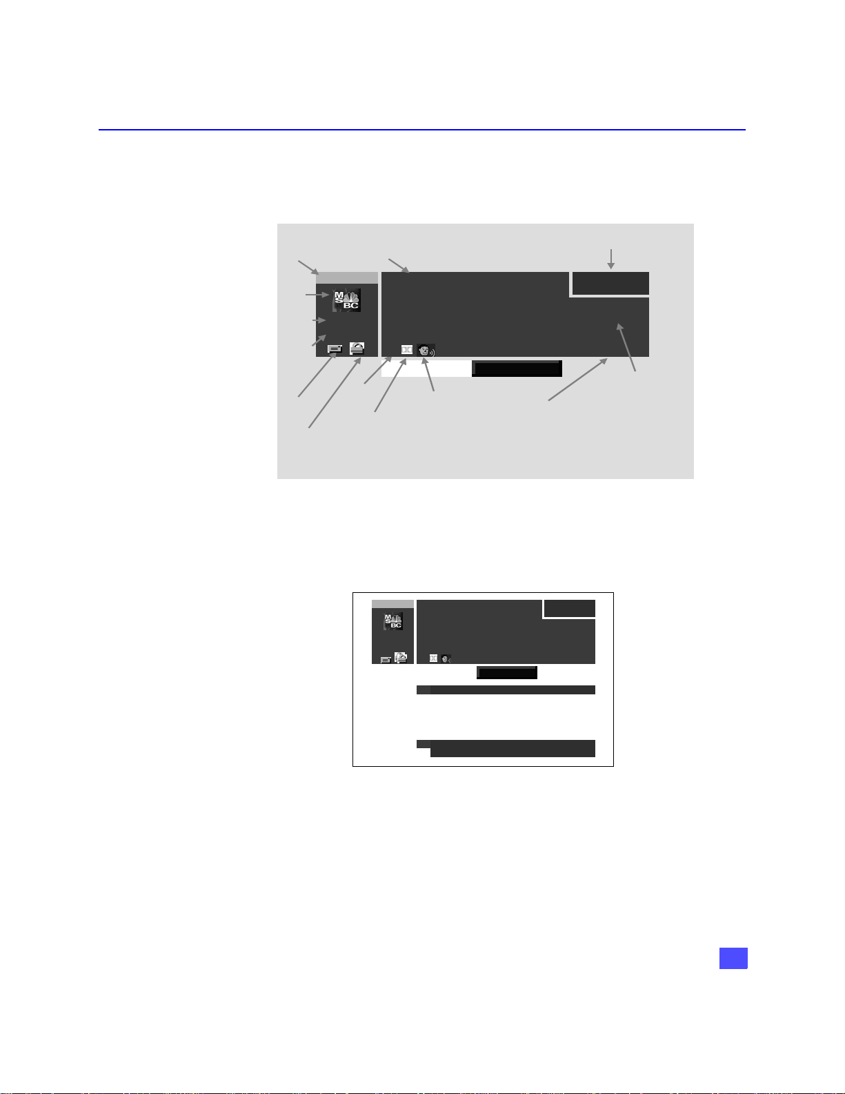
Channel Banner: Components
The HDTV Digital Receiver is required to display to the user various attributes of a
program. The Channel Banner is used by all tuning methods to show you which
channel and program you are currently viewing or selecting. The figure below
indicates the various components of the Channel Banner.
Channel
Number
Channel
Logo
Channel
Name
Channel
Surf
Mode
(FAV CH
or
LL CH)
E-mail
icon
Lock
icon
345-78
MSNBC
FAV CH
Close
Caption
icon
Title
Sw ift, Sm art and Dea dly
9:00 PM - 10:00 PM
“Test the lim its of shark smarts with two New Zealand
researchers as they hand feed sharks…” Thriller,
Drama, Sports, HDTV, (1999)
John Smith, Jane Doe, Joe Miller -The Sharks… -
CC
TV PG SAT : HD
dd to FAV Delete from FA V
lterna te
Dolby
Digital
icon
icon
udio
Channel Mode
Time
9:15 PM
Sun 3/21/01
Description
Channel Banner Components
The following figure displays some of the information that can possibly be displayed,
simultaneously.
Swift, Smart and Deadly
345-78
9:00 PM - 10:00 PM
“Test the limits of shark smarts with two New Zealand
researchers as they hand feed sharks…” Thriller,
MSNBC
Drama, Sports, HDTV, (1999)
John Smith, Jane Doe, Joe Miller -The Sharks…-
FAV CH
CC
Add to FAV Delete from FAV
A
Audio Track English
A
9:15 PM
Sun 3/21/01
TV PG SAT : HD
Press INFO if you want to purchase this event.
E
Channel Banner with OSD Messages
21
Page 23

FEATURES OF THE HDTV DIGITAL RECEIVER
Icons: Channel Banner
The Channel Banner contains several icons that are displayed only when the feature
is available and is supported by the HDTV Digital Receiver. The following figure and
table depicts the location and appearance of these icons.
Icon Name Icons Description Icon Appearance
Viewing Modes
Messages
Lock
Alternate Audio
Closed Captioning
Dolby Digital indication
Indicates that there is an unread
message.
Indicates that the channel is locked
due to either limits on spending or
by content advisory.
Indicates that the current program
has multiple audio tracks.
Indicates that the program has
Closed Captioning.
Indicates that the program has
Dolby Digital Audio.
CC
This section describes the user interface that is directly controlled by remote or front
panel. The following operational modes are supported by this interface:
• Normal Viewing Mode (includes closed captioning)
• Tuning Mode
• Recall Display Mode
• Aspect Ratio Change Mode
• Exiting Tuning Mode
22
Normal Viewing Mode
Normal Viewing Mode is defined as only the video being displayed and possibly
closed captioning data. When HDTV Digital Receiver is first powered on, it will be in
the Normal Viewing mode.
Note: The first time the HDTV Digital Receiver is powered On, all channels except those
exceeding the MPAA or TV rating limits and channels not authorized by the DIRECTV
are shown.
Once the user has created a favorite channel list, the HDTV Digital Receiver will
channel surf only to channels that are part of the favorite channel list. The user may
tune to a channel that is not a member of the favorite channel list by entering in a
channel number, explained in the Direct Tuning Method section. The user must add
this channel using the menu system.
Page 24

Tuning Mode
FEATURES OF THE HDTV DIGITAL RECEIVER
Closed Captioning Suspension
When any OSD is required (i.e. Channel Banner, messages from DIRECTV, etc.), any
captioning service that is currently active will be removed from the display and any
further captioning will be suspended until the OSD operation completes.
Power On Requirements
When the HDTV Digital Receiver is powered on, the receiver will tune to the last tuned
channel. If this channel no longer exists, the receiver will tune to channel 100. Prior to
initial setup of the receiver, the receiver may automatically go to Setup menu or tune
to channel 100.
The Tuning Mode happens when the user attempts to change the channel. The HDTV
Digital Receiver will support 3 ways to change the channel, as outlined below:
Method Result
• Direct Tuning (0-9 and PROG keys) Tunes directly to a channel using
either single or compound numbers.
• Channel UP/Down Tuning (FGkeys) Tunes to the next/previous available
channel.
• Rapid Tune (R-TUNE) Switches between the last two
channels, accessed. This is
accomplished using the R-TUNE key
on the remote.
Direct Tuning Method
The HDTV Digital Receiver supports the tuning of either single or compound channel
numbers. The single channel numbers range from (0 to 9999) and compound channel
numbers (major-minor) can range from (0-0 to 999-99)*. The compound channel
number uses the “PROG” button to enter the minor number field. Following is an
example of Direct tuning screen.
345-78
MSNBC
FAV CH
Star Battle
9:00 PM - 10:00 PM
“The battle of the universe begin when the evil…”
CC
Direct Tuning example
Sun 3/21/01
TV PG SAT : HD
9:15 PM
*For example, 120-1 is an example of a compound number. 120 is the major number
and 1 is the minor number.
23
Page 25

FEATURES OF THE HDTV DIGITAL RECEIVER
Example of Non-compound (Single) Channel Number Input
For example, to tune channel 345, you enter the channel number by using the number
keys (0-9) on the remote control. Then press the ACTION button which causes the
tuning event to occur.
Example of Compound Channel Number Input
A compound numbers (major-minor) can range from (0-0 to 999-99). For example, to
enter channel number 345-78, you do the following.
• Press the numeric buttons 3, 4 and 5 on the remote control.
•Press PROG button to enter the minor number field.
• Press number 7 and 8 buttons on the remote control.
•Press ACTION button to complete the tuning event.
Note: If you do not enter a number after 2 seconds, the number 0 is assumed for the minor
number.
Unavailable Channel Selection
The “Channel Not Available” screen is displayed when you select an unavailable
channel. The following is a list of some possible situations where an unavailable
channel selection may occur.
H Tuning to a channel that is not transmitting any programs.
H Tuning to a channel that is blocked either by spending or content advisory limits.
H The signal strength of the RF signal is insufficient to obtain consistent error free data.
Following is a example of Channel Not Available screen.
Random Hearts
119
DTV
ALL CH
4:30 PM - 5:45 PM
Movie, Drama, Harrison Ford, Kristin Scott Thom
RSAT: SD
CAM Rating Limit Exceeded.
Press ACTION to Override.
Channel Not Available Screen
6:00 PM
Wed 05/03/00
24
Page 26

If you tune to a channel that is blocked either by spending or advisory limits, a
corresponding screen will appear. The following is an example of insufficient credit.
Note: The screen remains displayed for 60 seconds, then is replaced by a blank screen.
Dolby Digital (AC-3) Audio
Dolby Digital (AC-3) 5.1 channel surround sound delivers digital-quality sound. AC-3
provides five discrete full-bandwidth channels for front left, front right, center, surround
left and surround right, plus a LFE (Low Frequency Effect) subwoofer channel.
External Dolby Decoder (Optional)
For a full Home Theater sound experience, an external AC-3 decoder and
multichannel amplifier must be connected to the HDTV Digital Receiver.
Stereo Output
The internal decoder converts compressed audio data, up to 5.1 channels, into two
digital quality stereo audio outputs, delivering stereo sound.
Note: The stereo audio outputs are Dolby Surround compatible. You can connect a Dolby
Surround Pro Logic decoder (not included) to the stereo audio outputs and receive
surround sound.
FEATURES OF THE HDTV DIGITAL RECEIVER
For ordering information, please call
i
customer service, ext. 732.
25
Page 27

FEATURES OF THE HDTV DIGITAL RECEIVER
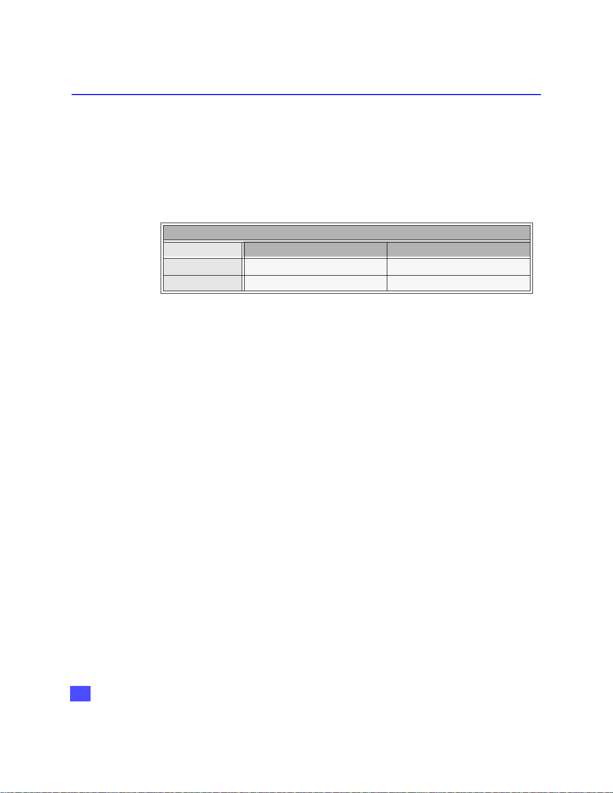
Aspect Ratio Change Mode
The ASPECT key on the remote allows you to change the manner in which the video
is presented on the display. The ability to change the video aspect is based upon the
video input source aspect and the output display, as shown below.
Video Input Source Aspect Output Display Aspect Possible Conversion
16:9 16:9 Full
16:9 4:3
4:3 4:3 Full
4:3 16:9 Full Sidebar
Note: When you exit the Tuning Mode and enter either the Menu or APG the following OSD
related feature and message are disabled.
• Tuning Methods are suspended.
• Closed Captioning suspended.
• Authorization messages are suspended.
Letterbox (default)
Full - Zoom
26
Page 28

Getting Started
Step 1. Connect AC Power Cord
Plug the AC power cord into a grounded outlet. Do not turn on any devices until you
have finished making all necessary connections.
Step 1a. Antenna/Cable Connection
Connect the antenna or cable wire to the ANT IN jack on the rear panel of the HDTV
Digital Receiver.
GETTING STARTED
Incoming signal from
antenna or cable
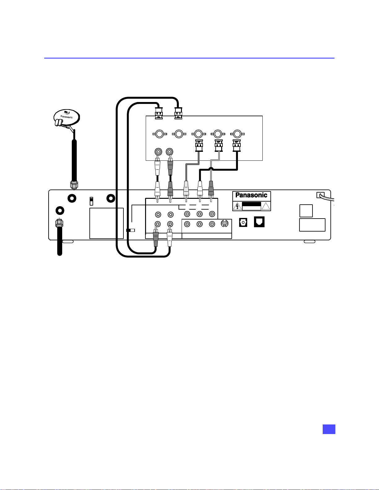
Step 1b. DIRECTV Satellite dish Connection
Connect the DIRECTV Satellite dish downlead to the SATELLITE IN jack on the rear
panel of the HDTV Digital Receiver.
SATELLI TE
ANT IN
Note: The shape of your satellite dish antenna determines what type of signal that your
antenna can receive. If you have an oval shaped dish, you can receive signals from
DIRECTV Satellites, including HD programming.
IN
CH 3
CH 4
RF OUT
ANT IN
SATELLI TE
IN
CH 3
CH 4
RF OUT
27
Page 29

GETTING STARTED
Step 2. HDTV Digital Receiver Connection to DTV-Compatible TV
Follow this diagram when connecting the HDTV Digital Receiver to a DTV-compatible
TV.
Incoming Ant.
or
cable signal
ANT IN
SATELLITE
IN
RF OUT
CH 3
CH 4
MODEL NO.
SERIAL NO.
AC 120V 60Hz
MAX AMPS
MANUFACTURED
Incoming Satellite
signal
ANT IN
RGB/YPBP
INPUT
STB
R
DTV-COMPATIBLE TV
AUDIO
R L
R-AUDIO-L
H-SYNC-L
DIGITAL OUTPUT
P
R
R
P
RPB
R
R-AUDIO-L VIDEO
Y
P
B
G
B
Y
B G
NTSC OUTPUT
HDTV Digital Receiver
S-VIDEO
NOTE: COMPONENT VIDEO CABLES,
AUDIO CABLES AND MODEM CABLE
NOTE: AUDIO CABLES
NOT INCLUDED
HDTV DIGITAL RECEIVER
WARNING
RISK OF ELECTRIC SHOCK
DO NOT OPEN
DIGITAL
AUDIO OUT
(AC-3)
TEL LINE
INCLUDED.
®
!
ASSEMBLED IN MEXICO
DISTRIBUTED BY
MATSUSHITA ELECTRIC
CORPORATION OF AMERICA
ONE PANASONIC WAY,
SECAUCUS, NEW JERSEY 07094
DTV-COMPATIBLE TV SETUP
Procedure
• Set the RGB/YPBPR switch to YPBPR position.
• Connect video cables from the Y, PB, PR digital TV video output jacks on the HDTV Digital
Receiver to the Y, PB, PR digital TV video input jacks on the DTV-compatible TV.
• Connect audio cables from the left and right digital TV audio output jacks on the HDTV
Digital Receiver to the left and right digital TV audio input jacks on the TV.
• Select the Video out mode according to the capability of your DTV compatible TV.
Note: Modem should also be connected to a telephone jack using the supplied modem cable
if impulse pay per view services are desired.
Note: There are three video inputs, Y, P
luminance and color difference signals.
. Separate component video inputs provide
B, PR
28
Page 30
Step 2a. HDTV Digital Receiver Connection to RGB Monitor
Follow this diagram when connecting the HDTV Digital Receiver to a Monitor with
RGB INPUTS.
RGB MONITOR
RGB INPUTS
R G BH V
AUDIO
LR
GETTING STARTED
NOTE: RGB cables not
included.
RF OUT
CH 3
CH 4
MODEL NO.
SERIAL NO.
AC 120V 60Hz
MAX AMPS
MANUFACTURED
RGB/YPBP
R
R-AUDIO-L
H-SYNC-L
DIGITAL OUTPUT
P
RPB
R
R-AUDIO-L VIDEO
Y
B G
NTSC OUTPUT
S-VIDEO
HDTV DIGITAL RECEIVER
WARNING
RISK OF ELECTRIC SHOCK
DO NOT OPEN
DIGITAL
AUDIO OUT
(AC-3)
®
!
TEL LINE
ANT IN
SATELLITE
Terrestrial or
Cable Antenna
IN
HDTV DIGITAL RECEIVER CONNECTION TO RGB MONITOR
Procedure
• Connect video cables from the RGB output of the HDTV Digital Receiver to the RGB inputs
of your Monitor.
• Connect the H,V output cables from HDTV Digital Receiver to the H,V inputs of your
Monitor.
• Set the RGB/YPBPR switch to the RGB position.
• Connect the audio cables from the left and right digital audio output jacks on the HDTV
Digital Receiver to the left and right digital audio jacks on the RGB monitor.
• Select the HDTV Digital Receiver video output according to the capability of your RGB
monitor (Hybrid, Native, 1080i or 720i).
Note: Modem should also be connected to a telephone jack using the supplied modem cable
if impulse pay per view services are desired.
HDTV DIGITAL RECEIVER
DISTRIBUTED BY
MATSUSHITA ELECTRIC
CORPORATION OF AMERICA
ONE PANASONIC WAY,
SECAUCUS, NEW JERSEY 07094
ASSEMBLED IN MEXICO
29
Page 31

GETTING STARTED
Step 2b. HDTV Digital Receiver connection to Conventional TV
Follow this diagram when connecting the HDTV Digital Receiver to a conventional TV
or Monitor. Terrestrial and digital signal can be received by connecting the digital
receiver to the TV or Monitor.
CONVENTIONAL TV/MONITOR
VIDEO
AUDIO
R L
INPUT
ANT IN
S -VIDEO
NOTE: S-VIDEO AND VIDEO
CABLES NOT INCLUDED
Connect the
S-Video or
video cable.
See Note
below.
ANT IN
SATELLITE
IN
MODEL NO.
SERIAL NO.
AC 120V 60Hz
MAX AMPS
MANUFACTURED
TERRESTRIAL OR
CABLE ANTENNA
CH 3
CH 4
RF OUT
RGB/YPBP
R
R-AUDIO-L
H-SYNC-L
DIGITAL OUTPUT
P
RPB
R
R-AUDIO-L VIDEO
Y
B G
NTSC OUTPUT
S-VIDEO
HDTV DIGITAL RECEIVER
WARNING
RISK OF ELECTRIC SHOCK
DO NOT OPEN
DIGITAL
AUDIO OUT
(AC-3)
TEL LINE
®
!
DISTRIBUTED BY
MATSUSHITA ELECTRIC
CORPORATION OF AMERICA
ONE PANASONIC WAY,
SECAUCUS, NEW JERSEY 07094
ASSEMBLED IN MEXICO
HDTV DIGITAL RECEIVER
CONVENTIONAL TV SETUP
Procedure
• Select 480i mode by using the Video Out button on the front panel.
• Connect the RF OUT to the ANT IN of the television or connect video cable from the video
output jack on the HDTV Digital Receiver to the video input jack on the TV.
OR
• Connect S-VIDEO Cable from the NTSC S-VIDEO output jack on the HDTV Digital
Receiver to the S-VIDEO input jack on the TV.
Note: Connect either the S-Video or video input/output as shown above.
• S-Video will provide better picture quality.
• If both S-Video and video are connected, S-Video will override video.
• Connect audio cables from the left and right NTSC audio output jacks on the HDTV Digital
Receiver to the left and right audio input jacks on the TV.
Note: Modem should also be connected to a telephone jack using the supplied modem cable
if impulse pay per view services are desired.
30
Page 32

GETTING STARTED
Step 3. Digital TV Reception with DTV-Compatible TV / Monitor (no satellite or
cable service)
Follow this diagram if you have a DTV-compatible TV, no satellite or cable service.
Digital and Standard terrestrial channels can be viewed by connecting the HDTV
Digital Receiver.
NOTE:
TERRESTRIAL
ANTENNA
SATELLITE
ANT IN
IN
CH 3
CH 4
MODEL NO.
SERIAL NO.
AC 120V 60Hz
MAX AMPS
MANUFACTURED
RF OUT
ANT IN
RGB/YPBP
DTV-Compatible TV
AUDIO
RL
INPUT
R-AUDIO-L
R
H-SYNC-L
DIGITAL OUTPUT
R
R
PRPBY
R
R-AUDIO- L VI DEO S- VIDEO
G
B
BG
NTSC OUTPUT
Y
P
P
B
ANTENNA AND RF CABLES NOT
HDTV DIGITAL RECEIVER
HDTV DIGITAL RECEIVER
WARNING
RISK OF ELECTRIC SHOCK
DO NOT OPEN
DIGITAL
AUDIO OU T
(AC-3)
TEL LINE
INCL UDED
®
!
DISTRIBUTED BY
MATSUSHITA ELECTRIC
CORPORATION OF AMERICA
ONE PANASONIC WAY,
SECAUCUS, NEW JERSEY 07094
ASSEMBLED IN MEXICO
HDTV DIGITAL RECEIVER, DTV COMPATIBLE TV/MONITOR
(NO SATELLITE OR CABLE SERVICE)
Procedure
• Connect the antenna cable to the ANT IN jack of the HDTV Digital Receiver.
• Connect the RF OUT signal to a DTV-compatible TV ANT IN (antenna) jack using standard
RF cables with coaxial connectors.
• Connect the component video and audio cables as shown above.
• Leave the RGB/YP
• Select the video out mode according to the capability of your DTV-Compatible TV.
switch in the YPBPR position.
BPR
31
Page 33

GETTING STARTED
Step 3a. Digital TV Reception with Conventional TV (no satellite or cable service)
Follow this diagram if you have a conventional TV, no satellite or cable service. Digital
and analog channels can be viewed by connecting the HDTV Digital Receiver.
CONVENTIONAL TV/ MONITOR
INPUT
AUDIO
RL
VIDEO
S -VIDEO
ANT IN
NOTE:
RF CABLES, S- VIDEO AND
VIDEO CABLES NOT INCLUDED
HDTV DIGI TAL RECEIVER
CH 3
CH 4
MODEL NO.
SERIAL NO.
AC 120V 60Hz
MAX AMPS
MANUFACTURED
RF OUT
RGB/YPBP
R
R-AUDIO-L
H-SYNC-L
PRPBY
BG
R
R-AUDIO- L VIDEO S-VI DEO
NTSC OUTPUTDIGIT AL OUTPUT
HDTV DIGITAL RECEIVER
WARNING
RISK OF ELECTRIC SHOCK
DO NOT OPEN
DIGITAL
AUDIO OUT
(AC-3)
TEL LINE
®
!
DISTRIBUTED BY
MATSUSHITA ELECTRIC
CORPORATION OF AMERICA
ONE PANASONIC WAY,
SECAUCUS, NEW JERSEY 07094
ASSEMBLED IN MEXICO
ANT IN
SATELLITE
IN
HDTV DIGITAL RECEIVER, CONVENTIONAL TV/MONITOR
(NO SATELLITE OR CABLE ANTENNA)
Procedure
• Select 480i mode by using the Video Out button on the front of the HDTV Digital Receiver.
• Connect the antenna cable to the ANT IN.
• Connect the RF OUT to the ANT IN of the television or connect Audio and Video cables as
shown.
Note: Connect either the S-Video or video input/output as shown above.
• S-Video will provide better picture quality.
• If both S-Video and video are connected, S-Video will override video.
• Connect audio cables from the left and right NTSC audio output jacks on the HDTV Digital
Receiver to the left and right audio input jacks on the TV.
32
Page 34

GETTING STARTED
Step 3b. Digital TV Reception with DTV-Compatible TV (Cable service and
terrestrial antenna)
Follow this diagram if you have a DTV-compatible TV, cable service and terrestrial
antenna.
Incoming cable signal
Optional Cable Box
ANT
IN
ANT
OUT
NOTE: ANTENNA, A/B SWITCH, CABLE
BOX AND RF CABLES NOT INCLUDED.
DTV-Compatible TV
A/B
SWITCH
INPUT
ANT IN
AUDIO
LR
P
P
R
R
Y
B
B
G
HDTV DIGI TAL RECEIVER
ANT IN
SATELLITE
IN
CH 3
CH 4
MODEL NO.
SERIAL NO.
AC 120V 60Hz
MAX AMPS
MANUFACTURED
RF OUT
RGB/YPBP
R
R-AUDIO-L
H-SYNC-L
DIGITAL OUTPUT
P
RPB
R
R-AUDI O-L VI DEO
Y
BG
NTSC OUTPUT
S-VIDEO
HDTV DIGITAL RECEIVER
WARNING
RISK OF ELECTRIC SHOCK
DO NOT OPEN
DIGIT AL
AUDIO OUT
(AC-3)
TEL LINE
®
!
DISTRIBUTED BY
MATSUSHITA ELECTRIC
CORPORATION OF AMERICA
ONE PANASONIC WAY,
SECAUCUS, NEW JER SEY 07094
ASSEMBLED IN MEXICO
HDTV DIGITAL RECEIVER WITH DTV-COMPATIBLE TV WITH CABLE
SERVICE AND TERRESTRIAL ANTENNA
Procedure
• Connect the antenna cable to one input (A or B) of the A/B switch .
• Connect the incoming cable signal to the ANT IN of the cable box. Connect the ANT OUT
from the cable box to the other input (A or B) of the A/B switch.
• If not using a cable box, connect the cable to the other input of the A/B switch (not shown).
• Connect the HDTV Digital Receiver RF OUT jack to the DTV-compatible TV ANT (antenna)
IN jack using a RF cable.
• Connect the component video outputs and audio output from the HDTV Digital Receiver to
the input jacks of the DTV-Compatible TV.
• Select the Video out mode according to the capability of your television.
33
Page 35

GETTING STARTED
Step 3c. Digital TV/Cable Reception with Conventional TV
Follow this diagram if you have a conventional TV, cable service and terrestrial
antenna.
I
ncoming Cable signal
ANT
IN
ANT
OUT
CABLE BOX
CONVENTIONAL TV or MONITOR
AUDIO
R L
INPUT
VIDEO
NOTE:
ANTENNA, A/B SWITCH, RF
CABLES, CABLE BOX, VIDEO AND
S-VIDEO CABLES NOT INCLUDED.
S -VIDEO
A/B
ANT IN
SWITCH
SATELLITE
IN
MODEL NO.
SERIAL NO.
AC 120V 60Hz
MAX AMPS
MANUFACTURED
CH 3
CH 4
RF OUT
RGB/YPBP
R
ANT IN
R-AUDIO-L
H-SYNC-L
DIGITAL OUTPUT
Y
P
RPB
R
R-AUDIO-L VIDEO
R
B G
NTSC OUTPUT
S-VIDEO
HDTV DIGITAL RECEIVER
HDTV DIGITAL RECEIVER
WARNING
RISK OF ELECTRIC SHOCK
DIGITAL
AUDIO OUT
(AC-3)
DO NOT OPEN
®
!
TEL LINE
DISTRIBUTED BY
MATSUSHITA ELECTRIC
CORPORATION OF AMERICA
ONE PANASONIC WAY,
SECAUCUS, NEW JERSEY 07094
ASSEMBLED IN MEXICO
DIGITAL TV/CABLE RECEPTION WITH CONVENTIONAL TV (CABLE
SERVICE AND TERRESTRIAL ANTENNA)
34
Procedure
• Select 480i by using the Video Out button on the front of the HDTV Digital Receiver.
• Connect the antenna cable to one of the inputs (A or B) of the A/B switch.
• If using a cable box, connect the cable wire from the wall jack to the cable box ANT
(antenna) IN jack using a standard RF cable with coaxial connector and connect the cable
box ANT (antenna) OUT jack to the other input (A or B) of the A/B switch.
• If not using a cable box, connect the cable wire from the wall jack to the second input of the
A/B switch using an RF cable (not shown).
• Connect the OUT signal of the A/B switch to the ANT IN jack of the HDTV Digital Receiver.
• Connect the RF OUT jack to the Conventional TV or Monitor by suing a RF cable.
• Connect the NTSC OUTPUTS of the digital receiver to the A/V inputs of the television or
monitor.
Page 36

Step 3d. Digital 8VSB Cable/Analog Cable with DTV-Compatible TV
Follow this diagram if you have a DTV-compatible TV, cable service providing 8VSB
digital cable, cable box and you want to receive digital cable channels through the
HDTV Digital Receiver and analog cable channels through the cable box. Please take
note that the HDTV Digital Receiver can receive 8 VSB as well as the unscrambled
analog cable channels. Therefore, if you have no cable box, the 8VSB cable can be
directly connected to the HDTV Digital Receiver.
Note: The HDTV Digital Receiver is able to receive DTV signals from your local cable
provider only if they are transmitted in the 8VSB modulation format approved by the
FCC for DTV transmission. Also, your cable provider may elect to transmit in the
8VSB format for only a limited period of time. Please contact your cable provider to
determine if 8VSB modulation is available
Optional Cable Box
Optional Cable Box
GETTING STARTED
8VSB Signal
ANT
ANT
OUT
IN
NOTE: ANTENNA, SPLITTER, CABLE BOX
NOTE: ANTENNA, SPLITTER, CABLE
AND RF CABLES NOT INCLUDED
BOX, RF CABLES AND AUDIO CABLES
NOT INCLUDED
DTV-Compatible TV
SPLITTER
ANT IN
SATELLITE
IN
RF OUT
HDTV Digital Receiver
CH 3
CH 4
MODEL NO.
SERIAL NO.
AC 120V 60Hz
MAX AMPS
MANUFACTURED
RGB/YPBP
DTV-Compatible TV
INPUT
ANT IN
R-AUDIO-L
R
H-SYNC-L
DIGITAL OUTPUT
AUDIO
LR
P
P
B
R
B
R
P
RPB
BG
R
R-AUDI O-L VI DEO
NTSC OUTPUT
Y
G
HDTV DIGI TAL RECEIVER
WARNING
DO NOT OPEN
TEL LINE
®
!
DISTRIBUTED BY
MATSUSHITA ELECTRIC
CORPORATION OF AMERICA
ONE PANASONIC WAY,
SECAUCUS, NEW JERSEY 07094
ASSEMBLED IN MEXICO
S-VI DEO
HDTV DIGITAL RECEIVER
RISK OF ELECTRIC SHOCK
DIGITAL
AUDIO OUT
(AC-3)
Y
DIGITAL 8VSB CABLE/ANALOG CABLE RECEPTION WITH
DTV-COMPATIBLE TV SETUP
Procedure
• Connect the cable from the wall jack to the splitter using a standard RF cable with coaxial
connectors.
• Connect one splitter output to the HDTV Digital Receiver ANT IN jack using a RF cable.
• If using a cable box, connect the other splitter output to the cable box ANT (antenna) IN
jack using a RF cable. Connect the cable box ANT (antenna) OUT jack to the DTVcompatible TV ANT (antenna) IN jack using a RF cable.
• If not using a cable box, connect the 8VSB cable directly to the HDTV Digital Receiver.
• Follow directions in Getting Started section to connect the HDTV Digital Receiver to a DTVcompatible TV.
35
Page 37

GETTING STARTED
Step 3e. Digital 8VSB Cable/Analog Cable with Conventional TV
Follow this diagram if you have a conventional TV, cable service providing 8VSB
digital cable cable box and you want to receive digital cable channels through the
HDTV Digital Receiver and analog cable channels through the cable box. Please take
note that the HDTV Digital Receiver can receive 8 VSB as well as the unscrambled
analog cable channels. Therefore, if you have no cable box, the 8 VSB cable can be
directly connected to the HDTV Digital Receiver.
Note: The HDTV Digital Receiver is able to receive DTV signals from your local cable
provider only if they are transmitted in the 8VSB modulation format approved by the
FCC for DTV transmission. Also, your cable provider may elect to transmit in the
8VSB format for only a limited period of time. Please contact your cable provider to
determine if 8VSB modulation is available
Opti onal Cable BoxAnalog Signal
ANT
IN
ANT
OUT
NOTE: ANTENNA, SPLITTER, CABLE BOX, RF
CABLES AND VIDEO CABLES NOT INCLUDED
TV
AUDIO
VIDEO
SPLITTER
INPUT
RL
S -VI DEO
ANT IN
ANT IN
8VSB SIGNAL
SATELLITE
IN
MODEL NO.
SERIAL NO.
AC 120V 60Hz
MAX AMPS
MANUFACTURED
CH 3
CH 4
RF OUT
RGB/YPBP
R
R-AUDIO-L
H-SYNC-L
DIGITAL OUTPUT
P
RPB
R
R-AUDIO- L VIDEO
Y
BG
NTSC OUTPUT
HDTV DIGITAL RECEIVER
HDTV DIGITAL RECEIVER
WARNING
RISK OF ELECTRIC SHOCK
DO NOT OPEN
S-VIDEO
DIGIT AL
TEL LINE
AUDIO OUT
(AC-3)
®
!
DISTRIBUTED BY
MATSUSHITA ELECTRIC
CORPORATION OF AMERICA
ONE PANASONIC WAY,
SECAUCUS, NEW JERSEY 07094
ASSEMBLED IN MEXICO
DIGITAL 8 VSB CABLE/ANALOG CABLE WITH CONVENTIONAL TV
Procedure
• Connect the cable from the wall jack to the splitter using a standard RF cable with coaxial
connectors.
• Connect one splitter output to the HDTV Digital Receiver ANT IN jack using a RF cable.
• If using a cable box, connect the other splitter output to the cable box ANT (antenna) IN
jack using a RF cable. Connect the cable box ANT (antenna) OUT jack to the TV ANT
(antenna) IN jack using a RF cable.
• If not using a cable box, connect the 8 VSB cable directly to the HDTV Digital Receiver.
• Follow directions in Getting Started section to connect the HDTV Digital Receiver to a
conventional TV.
36
Page 38

Step 4. Turning HDTV Digital Receiver On
Procedure
T
S
• Press the Remote Control STB mode button .
• Press the POWER button.
Note: Monitor/TV should also be turned on.
Step 5. Switching to DTV Mode (Panasonic TV models)
Press the Remote Control TV/VIDEO button until DTV or Component Video input
appears on the Monitor/TV screen. Select the same mode that the HDTV Digital
Receiver is connected to.
Note: Non-Panasonic brand televisions require switching to the component video input.
Step 6. Roller Guide Menu™
Getting Started
Press the MENU button to display the Roller Guide Menu*. Press the or arrow
on the ACTION button to rotate the Roller Guide. Press the arrow on the ACTION
button to exit the Roller Guide Menu.
Panasonic
GETTING STARTED
B
ROLLER GUIDE MENU SELECTIONS
IJ
for more features
Press SELECT to enter.
Note: To exit the Roller Guide Menu, press the arrow on the ACTION button or press the
MENU button.
Note: The name HDTV Digital Receiver and the term STB are interchangeable.
37
Page 39

GETTING STARTED
Step 6a. ACTION / Navigation Button
Press ACTION to select the Roller Guide Menu item. Press the or arrows to
highlight sub menus. Press the arrow to select features. Press the or arrows
to scroll through options within a feature. Press the arrow to return to main menu
items.
Remote ACTION / Navigation Button
Note: Be careful to press ACTION in the middle of the button. If you do not press in the
middle of the button, the arrow buttons may be activated.
Step 7. Antenna/Cable Mode
Select either Antenna or Cable mode, depending on the type of incoming signal you
are using.
Procedure
H In SET UP Menu, select Ant Input to choose either ANTENNA or Cable (IRC, HRC,STD
etc.).
Note: To view digital cable channels, your cable operator must be transmitting them in 8VSB
format, please contact your local cable operator.
H Press the ACTION button to save your selection.
H Press the arrow repeatedly to exit back to Roller Guide.
Note: Whenever the antenna or cable mode is changed, Timer will revert back to default
settings.
ACTION
38
Page 40

Step 8. HDTV Digital Receiver Connection to VCR/S-VIDEO VCR
Follow this diagram when connecting the HDTV Digital Receiver to a standard VCR or
S-VIDEO VCR.
NOTE: VIDEO, S-VIDEO AND AUDIO
CABLES NOT INCLUDED
INPUT
S-VIDEO
AUDIO
L
R
ANT IN
SATELLITE
IN
MODEL NO.
SERIAL NO.
AC 120V 60Hz
MAX AMPS
MANUFACTURED
TV
RF OUT
CH 3
CH 4
Incoming signal from
antenna or cable
RGB/YPBP
R
S-VI DEO
VIDEO
L
AUDIO
R
R-AUDIO-L
H-SYNC-L
DIGI TAL OUTPU T
INPUT
R-AUDIO- L
VIDEO
P
RPB
RB G
R-AUDIO- L VI DEO
Y
L
NTSC OUTPUT
S-VI DEO
S-VI DEO
VCR
HDTV DIGITAL RECEI VER
HDTV DIGITAL RECEIVER
WARNING
RISK OF ELECTRIC SHOCK
DIGITAL
AUDIO OUT
(AC-3)
DO NOT OPEN
!
TEL LINE
GETTING STARTED
®
DISTRIBUTED BY
MATSUSHITA ELECTRIC
CORPORATION OF AMERICA
ONE PANASONIC WAY,
SECAUCUS, NE W JERSEY 07094
ASSEMBLED IN MEXI CO
Incoming signal
from satellite
VCR/S-VIDEO VCR SETUP
Procedure
• Select 480i by using the Video Out button on the front of the HDTV Digital Receiver.
• Connect video cable from the video output jack on the HDTV Digital Receiver to the video
input jack on the VCR.
OR
• Connect the S-Video cable from the NTSC S-Video output jack on the HDTV Digital
Receiver to the S-Video input jack on the S-Video VCR.
• Connect audio cables from the left and right audio output jacks on the HDTV Digital
Receiver to the left and right audio input jacks on the VCR.
• Connect video cable from video output jack on the VCR to video input jack on TV.
OR
• Connect S-Video cable from S-Video output jack on the S-Video Vcr to S-Video input jack
on TV.
• Connect audio cables from the left and right audio output jacks on the VCR to the left and
right audio input jacks on the TV.
Note: Connect either your S-Video or video input/output.
• S-Video will provide better picture quality.
• If both S-Video and video are connected, S-Video will override video.
Note: This HDTV Digital Receiver incorporates an anticopy process technology that is
protected by U.S. patents and other intellectual property rights measures. The
anticopy process is licensed for non-commercial, home use only. Reverse
engineering or disassembly is prohibited.
39
Page 41

GETTING STARTED
Step 9. Programming Available NTSC/ATSC Channels
YOU MUST PERFORM THE AUTOMATIC CHANNEL PROGRAMMING BEFORE
MANUALLY ADDING AND DELETING CHANNELS BECAUSE OF THE DIGITAL
TUNING SYSTEM USED BY THE HDTV Digital Receiver. THIS METHOD WILL
ENSURE THAT EVERY AVAILABLE CHANNEL IS CAPTURED AND STORED INTO
MEMORY.
Automatic Channel Programming
The HDTV Digital Receiver will scan for all available channels and store them in
memory. The scan will normally take several minutes to complete.
Procedure
H In SET UP Menu, select Ant Setup to choose AUTO Scan to automatically scan and store
all channels with a signal.
H Press the arrow to select AUTO.
H Press the ACTION button to start the auto scan.
H Press the ACTION button to cancel the auto scan or exit back to SET UP Menu after the
auto scan is complete.
H Press the arrow once to exit back to Roller Guide.
Note: As more digital channels become available in your area, the AUTO
feature must be selected to store the new digital channels into memory.
Manual Channel Programming
After programming all available channels, you can use the MANUAL feature to
selectively add or delete channels.
Procedure
H In SET UP Menu, select Ant Setup to choose Add/Del Ch to manually add or delete
channels.
H Press the to enter sub-menu.
• Use the , arrow buttons and numeric keypad to select a channel.
• Use the and arrow buttons to delete or add channels.
H Press the ACTION button to exit back to Ant Setup Menu.
H Press the arrow once to exit back to Setup Menu.
40
Automatic Channel Programming
The AUTO feature must be selected first to ensure that all
available channels are captured and stored into memory.
Page 42

OPTIONAL CONNECTIONS
Optional Connections
HDTV Digital Receiver Connection to Dolby Digital AC-3 Decoder
Follow this diagram to connect the HDTV Digital Receiver to a Dolby Digital AC-3
decoder.
Dolby digital
AC-3 decoder
DIGITAL
S-VID EO
AUDIO IN
(AC-3)
HDTV DIGITAL RECEIVER
WARNING
RISK OF ELECTRIC SHOCK
DO NOT OPEN
DIGITAL
AUDIO OUT
(AC-3)
TEL LINE
DIGITAL TV
INPUT
L
R
C
®
!
Y
P
B
P
R
ANT IN
Incoming signal
satellite dish
CH 3
CH 4
MODEL NO.
SERIAL NO.
AC 120V 60Hz
MAX AMPS
MANUFACTURED
RF OUT
RGB/YPBP
SATELLITE
IN
Incoming signal f rom
antenna or cable
NOTE:
AC-3 DECODER AND DI GITAL
AUDIO CABLE NOT I NCLUDED
6-Channel Amplifier
& Speakers
HDTV Digital Receiver
R-AUDIO-L
R
H-SYNC-L
DIGITAL OUTPUT
PRPBY
BG
R
R-AUDIO- L VIDEO
NTSC OUTPUT
DISTRIBUTED BY
MATSUSHITA ELECTRIC
CORPORATION OF AMERICA
ONE PANASONIC WAY,
SECAUCUS, NEW JERSEY 07094
ASSEMBLED IN MEXICO
DTV-Compatible TV
DOLBY DIGITAL AC - 3 DECODER SETUP
Procedure
• Connect Digital Audio cable from the Digital Audio Out connection on the HDTV Digital
Receiver to the Digital Audio In connection on the Dolby Digital AC-3 decoder.
• If using a DTV-compatible TV, follow directions in Getting Started section to connect the
HDTV Digital Receiver to a DTV-compatible TV.
• If using a conventional TV, follow directions in Getting Started section to connect the HDTV
Digital Receiver to a conventional TV.
41
Page 43

REMOTE CONTROL
Remote Control
ASPECT (Ratio)
Select picture shape to match
signal and monitor format
POWER
Press to turn ON and OFF.
MENU
Press to access Roller Guide
Menu.
ACTION
Press to access sub menus or
display Main Menus.
LIGHT*
Press to light remote control for five
(5) seconds.
TV/VIDEO
Press to select Component Video,
TV or Video input mode.
VCR DVD AUX RCVR
STB TV CBL CD
Press to select remote operation
mode.
STB
Turns on the HDTV digital receiver.
GUIDE
Press to select STB Guide or DVD
menu
PROG (Program) / Dash
Press to enter the 2-digit minor
number in a compound channel
number.
“0” ~ “9”
Press numeric keypad to select
any channel.
R-TUNE
Press to switch to previously
viewed channel or program.
42
*To conserve battery life, the LIGHT function
can be disabled/enabled by pressing R-TUNE
and RECALL simultaneously.
CHANNEL
Press to select next channel or
program.
INFO/RECALL
Press to display time, channel
banner, and other options.
Page 44

REMOTE CONTROL FUNCTIONAL KEY CHART
Remote Control Functional Key Chart
Key Component Function
POWER
LIGHT
ALL COMPONENTS Turn components On and Off
REMOTE CONTROL Illuminate buttons
MUTE
TV AUX (RCVR) CBL
Mute audio
TV/VIDEO
ALL COMPONENTS Switch between component and TV
Change picture shape to fit format:
Full - Normal picture shape (16:9
ASPECT
STB
A
D
U
V
D
R
C
V
V
T
B
T
S
ACTION
CH
X
R
C
V
R
C
B
L
ALL COMPONENTS
C
D
TV DTV
or 4:3)
Zoom - Expand picture uniformly
Letterbox - Black bars above and
below picture
Sidebar/4:3 - 4:3 picture on wide
aspect screen with vertical bars
on both sides
Component mode selection for
Remote Control
Up navigation
Down navigation
Left and right navigation
Exit Roller Guide Menu
Select and adjust features
CH
ACTION
MENU
PROG
VOLUME
TV
STB
VCR
DVD
CBL
STB
DVD
STB
STB TV VCR DVD AUX (VCR2)
CBL
RCVR CD AUX (TAPE)
Roller Guide Menu
Main menu selections
Menu
Select
ENTER
Roller Guide Menu
Menu
Press to enter the 2- digit minor
number in a compound number.
TV volume down and up
Cable volume down and up
Receiver volume down and up
43
Page 45

REMOTE CONTROL FUNCTIONAL KEY CHART
Remote Control Functional Key Chart
Key Component Function
PAG E
CHANNEL
GUIDE
EXIT
VCR REC
MOVE
REW
SEARCH
STOP
SIZE
PLAY
PIP
FF
FREEZE
TV/VCR
OPEN/CLOSE
SWAP
PAUSE
STILL
PIP CHANNEL
VCR CHANNEL
SLOW
STB
DVD
RCVR
ALL COMPONENTS
STB
DVD
STB Exit Menus
VCR
AUX (Cassette Deck)
TV CABLE
DVD
CD
AUX (RCVR)
VCR
AUX (Cassette Deck)
TV CABLE
VCR DVD CD
AUX (VCR2 Cassette Deck)
TV CABLE
VCR DVD CD
AUX (Cassette Deck)
TV CABLE
DVD/LD
CD
AUX (RCVR)
VCR
AUX (Cassette Deck)
TV CABLE
VCR
DVD CD AUX (Cassette Deck)
TV CABLE
DVD/CD/LD
VCR
AUX (Cassette Deck and Tape)
TV
VCR CBL DBS
AUX (RCVR)
DVD
CD
CABLE
Page up /down
Skip up / down
Station up / down
Channel down
Channel up
Guide
Menus
Record
Move PIP
Skip / Search Rewind
Search Rewind
Decrease surround
Rewind
PIP channel search
Stop
Change PIP size
Play
PIP ON/OFF
Skip/Search Fast Forward
Search Fast Forward
Increase Surround
Fast Forward
Freeze PIP
Switch between TV and VCR
Open / Close
Switch Main Picture and PIP
Still / Pause
Pause
PIP channel up / down
Channel up / down
Center channel sound up / down (+/-)
Slow +/Repeat / Random
TV Channel Up / Down
44
Page 46

REMOTE CONTROL FUNCTIONAL KEY CHART
Remote Control Functional Key Chart
Key Component Function
R-TUNE
INFO / RECALL
1 2 3
4 5 6
7
TV CBL STB
DVD
CD (AUX)
AUX (Cassette Deck)
TV VCR DVD CABLE
STB
CD
TV STB VCR CABLE DVD
CD
RCVR
98
Previous channel
Title
Next disc
Deck A/B
On screen display
On screen display
Time format
Selects channel
Selects code
Selects track
Keys 1, 2, 3, and 4 selects A/V
Inputs, 5 = CD, 6 = Tuner, 7 =
Phono, 8 = Cassette Deck, 9 = Aux
0
Battery Installation
Incorrect installation can cause battery leakage and corrosion that will damage the
Remote Control.
Use two AA batteries:
Remove the battery cover by pushing in near the arrow and sliding the cover
back.
Install batteries matching (+) and (-) polarity signs.
Replace the battery cover.
Precautions
• Replace batteries in pairs.
• Do not mix battery types (zinc carbon with alkaline).
• Do not recharge, short-circuit, heat, burn, or disassemble batteries.
45
Page 47

SPECIAL REMOTE BUTTONS
Special Remote Buttons
Aspect Ratio Selections
The ASPECT button changes the aspect ratio (picture display shape) in response to
the source signal and monitor format. You can also change the aspect ratio for your
personal viewing preference. Each time the ASPECT button is pressed, the HDTV
Digital Receiver will cycle to the next available aspect ratio choice.
Full Aspect
16:9 or 4:3 picture will be displayed in the center of the viewing screen at full screen
width and height.
Zoom Aspect (4:3 Monitor receiving 16:9 source signal)
The picture will be expanded uniformly (width and height) to fill the viewing screen.
The picture will be cropped, either horizontally or vertically to fit the viewing screen.
The cropped portion of the original picture will be lost from view.
Note: To properly display Closed Captioning in some cases, the aspect ratio should be
changed from Zoom to Full.
Letterbox Aspect (4:3 Monitor)
Video formats with aspect ratios greater than 16:9 will be displayed at the proper
width, so no video information is lost. Black or gray bars will appear above and below
the picture.
Sidebar Aspect (16:9 Monitor)
4:3 pictures will be viewed on a wide aspect TV screen with vertical bars on both sides
of the picture.
Note: See following page for illustrations of the various aspect ratios.
ASPECT
46
Page 48

SPECIAL REMOTE BUTTONS
formats available when the HDTV Digital
Receiver receives a 16:9 source signal.
These pictures show the different aspect ratios
available with a 4:3 monitor format.
• The top pictures show the 4:3 monitor
• The bottom picture shows the 4:3 monitor
format available when the HDTV Digital
Receiver receives a 4:3 source signal.
These pictures show the different aspect ratios
The 16:9 and 4:3 pictures
available with a 16:9 monitor format.
represent the incoming
format available when the HDTV Digital
• The top picture shows the 16:9 monitor
source signals received by
the HDTV Digital Receiver.
Receiver receives a 16:9 source signal.
• The bottom pictures show the 16:9 monitor
formats available when the HDTV Digital
Receiver receives a 4:3 source signal.
47
Page 49

SPECIAL REMOTE BUTTONS
TV/Video
TV/VIDEO
The TV/VIDEO button allows you to select the mode of your TV. Each time the TV/
VIDEO button is pressed, the TV will cycle through Channel, Video 1, Video 2, Video 3
and DTV modes.
Note: Not all television models will display all the modes.
Menu
Program
MENU
PROG
_
Rapid Tuning
Recall
RECALL
The MENU button is used to enter and exit Roller Guide Menu system. Each time the
MENU button is pressed, the Roller Guide will appear on and disappear from the
viewing screen.
Press the PROG button to enter the 2 digit minor number in a compound number.
R-TUNE
The R-TUNE button quickly switches between two channels or programs. The HDTV
Digital Receiver will attempt to immediately tune to the last channel or program in its
memory. If programs are no longer transmitting on the channel, the Unavailable
Channel Screen will display and the HDTV Digital Receiver will automatically select
the first program available on the channel.
The RECALL button displays the Recall Screen for 6 seconds or until you press any
button (which automatically exits the Recall mode).
48
Page 50

Programming the Remote Control
The Universal Remote Control can be programmed to operate many manufacturers’
components using the component function buttons for VCR, DVD, AUX (RCVR, CD,
TAPE, CASSETTE DECK and LD), CBL, DTV, TV, or DBS. Follow the procedures for
programming your Remote Control with and without codes for the component.
Determine the manufacturer of the component and look in the table for the code.
Note: Be careful to press ACTION in the middle of the button. If you do not press in the
middle of the button, the arrow buttons may be activated. This will interrupt your
programming.
Programming With Code
• Confirm that the external component is plugged in and is turned on.
• Turn the component off.
• Press the ACTION and POWER button, together, for at least 5 seconds. All
mode buttons will flash, then let go of the buttons.
• Press appropriate component button (VCR, CBL, etc.) on the Remote
Control. The pressed button will illuminate steadily. All other buttons will go
out.
• Enter the 3-digit component code using the Remote Control numeric keypad
(0 ~ 9 buttons). If a proper code was entered, the mode button will blink twice
and go out.
• Press the Remote Control POWER button to test the component. If the
procedure was successful, the component will turn on.
PROGRAMMING THE REMOTE CONTROL
Programming Without Code
This procedure searches all codes and is called the “sequence method”.
• Confirm that the external component is plugged in and is turned on.
• Turn the component off.
• Press the ACTION and POWER button, together, for at least 5 seconds. All
mode buttons will flash, then let go of the button.
• Press appropriate component button on the Remote Control. The pressed
button will illuminate. All other buttons will go out.
• Press the button to move forward to the next code. Press the button to
move backward.
• Press the Remote Control POWER button to test the component. If the
procedure was successful, the component will turn on.
Note: Repeat the preceding two steps until the component code is found. It may take many attempts
before the correct code is found.
• After the code is found, press the ACTION button to store the code.
Unsuccessful Code
If the component does not operate with the Remote Control,
repeat the procedure using another code. (Some brands have
multiple codes.)
If an incorrect code is entered, or if the procedure takes longer
than 30 seconds, the programming will fail.
49
Page 51

COMPONENT CODES
Component Codes
The Universal Remote Control is capable of operating many component brands after entering a code.
Some components may not operate because memory is limited. The Universal Remote Control does not
control all features in all models.
Codes for TV
Brand Code
Akai 110
Centurion 112
Daewoo 120
Emerson 141, 143, 144
Fisher 150
GE/Panasonic/
Quasar
GE/RCA 162
Hitachi 180
JVC 190
Magnavox 210, 212
Marantz 220
101
Brand Code
ABC 530
Archer 531, 544
Cableview 005, 544
Citizen 005, 522
Curtis 130, 131
Diamond 530, 531, 544
Eagle 541
Eastern 560
GC Brand 005, 544
Gemini 522
General Instrument/Jerrold
Hamlin 130, 350, 720, 730, 731, 900
Hitachi 003, 530
Macom 003, 004, 005
Memorex 542
Movietime 005, 544
Oak 002, 702, 710
Panasonic 120, 121, 132
Philips 006, 541, 542
Pioneer 001, 260
Pulsar 005, 544
122, 360, 520, 521, 522, 530, 531, 532,
533
Brand Code
Panasonic 100, 101, 102
Pioneer 222
Proscan 230
Quasar 101, 103
Radioshack 240
RCA 250, 255
Samsung 260
Sears/Toshiba 130
Sharp 265
Sony 270
Zenith/Inteq 290, 291
Codes for Cable Box
Brand Code
Puser 544
Realistic 544
Regal 130, 350, 720, 730, 731, 900
Regency 560
Rembrandt 005, 544, 702
Samsung 005
Scientific Atlanta 122, 130, 131
Simark 001, 005
Sprucer 005, 121
Stargate 005, 544
Te le vie w 001, 005
Texscan 810
To co m 700, 701
To sh iba 004
Unika 531, 544
Universal 522, 544
Videoway 006
Viewstar 541, 542
Zenith 000, 280
Zenith/Drake
Satellite
000
50
Page 52

Codes for VCR
COMPONENT CODES
Brand Code
Admiral 200
Aiwa 137,160
Akai 014, 015, 016,142
Audio Dynamic 011, 240
Bell & Howell 005, 013
Broksonic 081, 136
Canon 125, 135
Citizen 006
Craig 005, 006, 141
Curtis Mathes 130, 137, 300
Daewoo 001, 130, 250
DBX 010, 011, 240
Dimensia 300
Emerson 003, 080, 081, 135, 136, 243, 250
Fisher 005, 007, 008, 009
Funai 081, 136, 137
GE 130, 170, 300
Go Video 220, 512
Goldstar 006
Hitachi 000, 125, 300
Instant Replay 125, 130
J.C. Penney 000, 005, 010, 011, 130, 240, 300
Jensen 240
JVC 010, 011, 190, 240
Kenwood 006, 010, 011, 240
LXI 000, 005, 006, 007, 008, 009, 137
Magnavox 125,130, 150
Marantz 010, 011, 240
Marta 006
Memorex 009, 130
MGA/Mitsubishi 230, 241, 242, 243, 330, 340
Minolta 000, 300
Mont.Wards 006, 009, 200, 210, 290
Multitech 004, 137, 330
NEC 010, 011, 190, 240
Olympic 125, 130
Optimus 006, 100, 140, 200
Brand Code
Orion 081, 136
Panasonic 100, 101, 125, 130
Pentax 000, 011, 300
Philco 081, 125,130, 136, 137, 150
Philips 125, 130, 150
Pioneer 125
Proscan 000, 001, 002, 125,130, 150, 300, 310
Quasar 100, 101, 125, 130
Radio Shack 005, 009, 130, 137, 170, 210, 241
RCA
Realistic 005, 009, 130, 137, 210, 241
Samsung 002, 004, 220
Sansui 081, 136, 240, 520
Sanyo 005, 009
Scott
Sears 000, 005, 006, 007,008
Shaintom 050
Sharp 200, 210
Signature 2000 137, 200
Singer 050
Sony 140, 141, 142
SV2000 137
Sylvania 125, 130, 137, 150
Symphonic 137
Ta sh i r o 006
Tatung 010, 011, 240
Te ac 010, 011, 137, 240
Technics 100, 101,125, 130
Te kn i k a 130, 137
To sh i b a 001, 310
Vector
Research
Yamaha 005, 010, 011, 240
Zenith 290
000, 001, 002, 125,130, 150, 170, 300,
310
001, 002, 004, 009,081,136, 230, 241,
330, 340
011
51
Page 53

COMPONENT CODES
Codes for CD
Brand Code
Carver 550
Denon 600
Fisher 405
Harman/Kardon
JVC 590, 591, 670
Kenwood 400, 401,450, 670
Magnavox 550
Marantz 550
McIntosh 460
Optimus 430, 459
Panasonic 500, 501, 530
459, 460, 462
Brand Code
Denon 100
Ferguson 110
Nordmende 110
Mitsubishi 150
Panasonic 100
Pioneer 120
Brand Code
Philips 550
Pioneer 430
Quasar 500, 501, 530
Sansui 432
Sanyo 405
Sharp 600
Sherwood 459
Sony 540
Technics 500, 501, 530
Victor 590, 591, 670
Yamaha 402, 403, 404
Codes for DVD
Brand Code
RCA 11 0
Saba 110
Sony 140
Thomson 11 0
To sh iba 130
Yamaha 100
Panasonic 500, 530
Technics 500, 530
Brand Code
Echo Star 110
GE 170
Hitachi 050
Panasonic 100
Philips 001, 002
52
Codes for Cassette Deck
Brand Code
Codes for DBS
Brand Code
Primestar 391
RCA 170
Sony 390
To sh i b a 000
Uniden 001, 002
Page 54

Codes for Laser Disc
Brand Code
Panasonic 200, 201, 235, 380
Pioneer 370
Sony 240, 241, 242, 243
Codes for Receiver/Amplifier
COMPONENT CODES
Brand Code
Admiral 710
Aiwa 760, 761
Denon 800, 801, 802
Fisher 604
Garrard 655
Harman 657, 750
Jensen 764
JVC 790,791
Kenwood 600, 650
Magnavox 762
Marantz 751
McIntosh 658
Nakamichi 631
Onkyo 651, 656
Brand Code
Optimus 603, 762, 770, 771
Panasonic 700, 701, 730
Philips 750
Pioneer 630, 632
Quasar 700, 701, 730
RCA 603, 630,762,770, 771
Sansui 603, 653,920
Sharp 800,803
Sony 740
Soundesign 820
Teac 653, 654, 655
Te ch n ic s 700, 701, 730
Victor 790, 791
Yamaha 601, 602
Write the code numbers for your components in the space provided below. This will serve as a
reference when you need to reprogram your remote control.
CABLE
Cable Box
VCR
Video Cassette
Recorder
RCVR
Receiver or Amplifier
LD
Laser Disc Playe
r
DBS
Direct Broadcast
Satellite
Other Components
TV
Television
Other Components
CD
Compact Disc Playe
Other Components
DVD
r
Digital Videodisc
Other Components
53
Page 55

SPECIAL FEATURES OF HDTV DIGITAL RECEIVER
Special Features of HDTV Digital Receiver
Impulse Pay Per View (IPPV)
You must connect your phone line to the HDTV Digital Receiver to receive pay per
view (PPV) service offered by DIRECTV. Connecting the phone line permits you to
use the IPPV feature, which allows event purchases without calling a CSR (Customer
Service Representative). If you decide against connecting to your phone line, you
must call the CSR to purchase events, such as Pay per view movies. DIRECTV refers
to such CSR assisted purchases as OPPV (Order ahead pay per view).
When OPPV or subscription authorization changes (e.g., customer cancels the movie
purchases), the HDTV Digital Receiver will reflect that change immediately. The
HDTV Digital Receiver will display a message, identifying the reason for the
authorization status change.
The HDTV Digital Receiver has the ability to allow you to purchase a PPV event
offered by DIRECTV. When the HDTV Digital Receiver is tuned to an IPPV channel,
(video may or may not be displayed, depending upon whether the PPV event has
started) the following message is displayed on the screen.
54
Press ACTION if you want to purchase this event.
i
IPPV message with video in the background
Page 56

SPECIAL FEATURES OF HDTV DIGITAL RECEIVER
If you press the INFO key, the PPV window will be displayed. Once a PPV event
starts, video and audio could be displayed for 5 minutes into the PPV event. After 5
minutes have elapsed, video and audio are removed from the screen. You can
purchase the current PPV event up to 30 minutes after an event has started. If the
PPV event passes the 30 minutes from the event starting time, a message will be
displayed and video will be blocked as shown below and you will not be able to
purchase the program.
Program not available in your area. Check
i
Program Guide for other show times.
Impulse pay per view: Icons
The Channel Banner will contain several icons that are displayed only when the
feature is available and is supported by the HDTV Digital Receiver.
The following figure depicts the PPV window. If you decide to buy the event or buy and
record the event, another confirmation window is displayed, requiring you to confirm
the purchase before completing the transaction.
345-78
Buy Event
Buy & Record
Other Times
Swift, Smart and Deadly
9:00 PM - 10:00 PM
“Test the limits of shark smarts with two New Zealand
researchers as they hand feed sharks…” Thriller,
Drama, Sports, HDTV, (1999)
John Smith, Jane Doe, Joe Miller -The Sharks…-
CC
Movie $3.50
6/01/00
9:15 PM
Sun 3/19/00
TV PG SAT : HD
PPV Window
55
Page 57

SPECIAL FEATURES OF HDTV DIGITAL RECEIVER
You will be given a choice of whether they wish to Purchase (OK) or Cancel this PPV
event, as shown below.
345-78
Swift, Smart and Deadly
9:00 PM - 10:00 PM
Buy Event
Buy & Record
Other Times
“Test the limits of shark smarts with two New Zealand
researchers as they hand feed sharks…” Thriller,
Drama, Sports, HDTV, (1999)
John Smith, Jane Doe, Joe Miller -The Sharks…-
CC
Movie $3.50
6/01/00
Do you want to purchase this event?
Cancel OK
PPV Confirmation Window (Buy Event)
345-78
Buy Event
Buy & Record
Other Times
Swift, Smart and Deadly
9:00 PM - 10:00 PM
“Test the limits of shark smarts with two New Zealand
researchers as they hand feed sharks…” Thriller,
Drama, Sports, HDTV, (1999)
John Smith, Jane Doe, Joe Miller -The Sharks…-
CC
Movie $3.50
6/01/00
Do you want to purchase this event?
Please remember to set display mode to 480I
and output to composite. Be sure that
your VCR is set for record.
Cancel OK
TV PG SAT : HD
9:15 PM
Sun 3/19/00
TV PG SAT : HD
9:15 PM
Sun 3/19/00
56
PPV Confirmation Window (Buy and Record Event)
You can also select other time to view this event, as shown below. After you have
selected a different time, the PPV confirmation screen is displayed.
345-78
Buy Event
Buy & Record
Other Times
Swift, Smart and Deadly
Ch: 345-78 Date: 11/28/01 Time: 9:00 PM
Ch: 345-78 Date: 11/29/01 Time: 9:00 PM
Ch: 345-78 Date: 11/29/01 Time: 11:00 PM
Ch: 345-78 Date: 11/30/01 Time: 9:00 PM
Ch: 345-78 Date: 11/30/01 Time: 11:00 PM
9:15 PM
Sun 3/26/00
PPV Other Times Window
Page 58

SPECIAL FEATURES OF HDTV DIGITAL RECEIVER
Software Upgrade Messages
The HDTV Digital Receiver has the ability to receive download replacement software.
This will allow the HDTV Digital Receiver software to be upgraded. The HDTV Digital
Receiver will prompt you when an update is required. You have the ability to reject or
cancel the update at this time. However, this notification will repeatedly occur until you
have upgraded the software.
The HDTV Digital Receiver will first display and update message when the unit is in
the tuning mode. This OSD will allows you to begin or cancel the software download,
as shown below.
<<<<
Software upgrade is required.
Do you wish to begin upgrade?
Software Upgrade Message
If the user elects to download software when prompted, an approximate time
remaining for download will be displayed, as shown below.
Start Cancel
<<<<
Time remain for software download…
5:20
Time Remain for Software Download
If you elect to cancel the download, the user will be prompted again to perform this
download every time the user turns ON the HDTV Digital Receiver. This software
download message will occur, until the HDTV Digital Receiver unit has been updated.
57
Page 59

ROLLER GUIDE MENU™
Roller Guide Menu™
Press the MENU button on the Remote Control to display the Roller Guide Menu™*.
Press the F or G arrow to rotate the Roller Guide. Press the ACTION button to enter
a category submenu screen, where the options for that category can be changed.
Press theJarrow to exit the Roller Guide Menu.
The Roller Guide screen is the entry point for all menu operations on the system. The
first time that the HDTV Digital Receiver is powered ON, the SET UP category is the
default state. The main menu provides access to the following categories:
•Guide
• Lock
• Account
• Options
• Setup
•Timer
Panasonic
ROLLER GUIDE MENU SELECTIONS
58
IJ
for more features
Press SELECT to enter.
Note: To exit the Roller Guide Menu, press the arrow on the ACTION button or press the
MENU button.
* Roller Guide Menu is a trademark of Panasonic Consumer Electronics Company. U.S. Patent Pending.
Page 60

ACTION / Navigation Button
Press the ACTION button to select main menu items. Press the or arrows to
highlight sub menus. Press the arrow to select features. Press the or arrows
to scroll through options within a feature. Press the arrow to return to main menu
items.
ROLLER GUIDE MENU™
Remote ACTION / Navigation Button
Note: Be careful to press ACTION in the middle of the button. If you do not press in the
middle of the button, the arrow buttons may be activated.
ACTION
59
Page 61

ROLLER GUIDE FEATURE CHART
Roller Guide Feature Chart
Roller Guide Feature Chart
MENU DESCRIPTION
Satellite Setup
Guide Setup
Ant Setup
MONITOR
System Test
Access Card
SET UP
H Dish Type - Lets you choose Oval or
Round dish.
H Auto Configuration - Enables the HDTV
Digital Receiver to automatically detect and
configure the correct satellite port settings.
H Sat. Ports - Selects up to 4 nominal
satellite configuration or lets you perform
auto-detection. The user can select:
• Dish Type : Oval or Round
• No Satellite
• Auto Configuration
• Satellite A and B
• Satellite A, B, and C
H Dish Position - Lets you orient the dish
antenna.
H Signal Meter - Shows the strength of the
selected satellite signal.
H Guide Setup - Lets you select the local
zip code for the local channels in your area.
These local channels should appear in the
APG.
H Ant Input - Selects the type of local input
sources.
H Off - Deactivates Terrestrial/Cable ATSC/
NTSC portion of the HDTV Digital
Receiver.
H Auto Scan - Allows you to retrieve all of the
antenna or unscrambled cable channel.
H Add/Del Ch - Lets you to add or delete the
channels that were detected by the auto
scan.
H TYPE
• 16:9 (default setting) for wide screen.
• 4:3 for conventional TV screen.
H System Test - Invokes system test
available for Satellite Input.
H Access card - Remapping of information.
(Use only when instructed by DIRECTV.)
60
Page 62

ROLLER GUIDE FEATURE CHART
Roller Guide Feature Chart (Cont.)
MENU DESCRIPTION
GUIDE
H Guide: Provides Channels and Program
Guide Setup
TIMER 1
TIMER 2
TIMER 3
TIMER 4
TIMER 5
TIMER 6
TIMER 6
TIMER 7
TIMER 8
information to the user.
Note: The Guide is active in the DIRECTV/
ATSC/NTSC mode only.
TIMER
H MODE - Select one of the following:
• OFF (default setting) to disable timer.
• ON to turn on HDTV Digital Receiver only.
(Must turn TV on to view the event).
• Repeat (weekly or once)
H DAY - Select the day of the week to
activate timer.
• START - Select time for timer to start.
• STOP - Select time for timer to stop.
H CHANNEL - Select the channel for STB to
tune to at appropriate time.
Note: Whenever the antenna or cable mode
is changed, Timers will revert back to
default settings.
Password
Movie Limits
TV Limits
Ch Locks
Spending
LOCK
H Password - A password, the user must
provide in order to perform a function.
H Movie Limits- Lets you block out movies
based on MPAA ratings.
H TV Limits- Lets you block out TV programs
based on TV Parental Guide ratings.
H Sat Lock - Lets you lock satellite or non
satellite channels from being displayed.
Need to enter password to view these
channels.
H This feature allows the user to control the
amount per event. If the amount is below
the event cost, you won’t be able to view
the event.
61
Page 63

ROLLER GUIDE FEATURE CHART
Roller Guide Feature Chart (Cont.)
MENU DESCRIPTION
Future Purchases
Past purchases
Messages
ACCOUNT
H Future purchases - Displays PPV events
purchased, but not aired. Also lets you to
cancel a PPV event.
H Past purchases - Lets you review PPV
purchased events. Displays CAM slot
numbers when Past purchase data is
highlighted.
H Messages - Displays message sent to the
HDTV Digital Receiver from DIRECTV over
the Satellite Link.
OPTIONS
Audio
Closed Caption
Clock
Sat/Loc Mode
Favorites
About
H Audio - Selects the Format and Language
preferences.
H Closed Caption - Select closed captioning
or text services.
H CC1-CC4 - for closed captioning services.
H T1-T4 - for text services.
H Clock - Lets you configure the system clock
for DIRECTV or NTSC. (Clock must be set
to use the Timer feature.)
H Sat/Loc Mode - Selects between between
Satellite tuning mode and Local tuning
mode.
H Favorites - Lets you add or delete channels
from the favorite list.
H About - Displays various information about
the HDTV Digital Receiver including the
Tech support number, serial number, model
number, etc.
62
Page 64

Roller Guide Menu Operations
Setup
To help you with the initial set up of the digital receiver, the Setup menu is displayed
automatically when the HDTV Digital receiver is turned on for the first time. A setup
wizard will help guide you through the procedeure of setting up the proper satellite
configurations, guide setup, and antenna setup. The Setup options will assist you to
configure the DIRECTV or/and ATSC / NTSC signals so that the unit can receive the
desired video signals. Following are requirements that are needed to receive either
the DIRECTV or NTSC signals. Following table shows the Setup options for different
signals.
Option
Sat. Setup Yes No
Guide Setup Yes No
Ant.Cbl Setup No Yes
Monitor Yes Yes
System Test Yes No
Access Card Yes No
ROLLER GUIDE MENU OPERATIONS
Setup Options
Required for DIRECTV HD /
ATSC/NTSC Setup
Required for ATSC/
NTSC Setup
Setup : Satellite Setup – Dish Type
This menu lets you select the type of satellite dish that you have installed. If you have
round dish, select Round and if you have oval shaped dish, select Oval. An Oval
shaped dish can receive both DIRECTV and DIRECTV HD signals.
q Sat Setup
Sat Ports
Dish Pos
Sig Meter
Press u to change Dish Type
Dish Type
Satellite Setup – Dish Type
u Oval
No Satellite
AutoConfiguration
u
Sat A and B
Sat A, B and C
Procedure
r Press u button to highlight Dish Type.
r Press u button to change Dish Type.
r Press pq to select either Round or Oval (Oval is the default setting). Oval shaped dish
lets you receive both DIRECTV and HD DIRECTV signals.
r Press ACTION button to save the selection.
r Press t button once to return to Sat. Setup menu.
63
Page 65

ROLLER GUIDE MENU OPERATIONS
Setup : Satellite Setup – Sat. Ports
You will be able to select 4 satellite port configurations - No Satellite, Auto
Configuration, Satellite A, B or Satellite A, B, C. The DIRECTV Plus Satellite Antenna
comes packaged with two LNB’s (Low Noise Block Down-converters) with a
multiswitch. The two LNB’s allow for reception of Satellite A, B. These satellites are
located at 101 degree WL and 119 degree WL. The DIRECTV Plus Satellite antenna
is also capable of accommodating a third LNB for future programming choices.
Therefore, if you plan to subscribe to DIRECTV services, including HDTV as well as
local to local broadcast channels, you should select Satellite A, B during this setup.
The multiswitch provided with the DIRECTV Plus satellite antenna enables you to
connect 4 different HDTV Digital Receivers in your home. Please consult your dealer
for more details. The HDTV Digital Receiver will allow you to begin auto-detection of
the antenna configuration or instead use one of the 4 nominal cases.
G Sat Setup
Sat Ports
Dish Pos
Sig Meter
Press K to setup satellite ports.
Satellite Setup – Sat. Ports Screen
Note: Please also refer to the installation manual for the satellite dish antenna for
proper mounting procedure.
Dish Type
K Oval
No Satellite
Auto Configuration
K
Sat A and B
Sat A, B and C
Procedure
H Press K and G button to setup satellite ports configuration.
H Press FG buttons to navigate among the choices - No Satellite, Auto Configuration, Sat.
A and B and Sat. A, B and C.
H Select Auto Configuration if you have Round Dish. Select Sat A & B, if you have Oval
shaped dish.
H Press ACTION button to save the selection.
H Press J button to return to Sat. Setup menu.
64
Page 66

ROLLER GUIDE MENU OPERATIONS
Setup : Satellite Setup – Dish position
This screen allows you to correctly position your Satellite antenna by receiving
elevation, azimuth and rotation ( marked in degrees), after the you have entered your
5-digit zip code.
G Sat Setup
Sat Ports
Dish Pos
Sig Meter
Press K to change the zip code.
Zip code for position 92154
Elevation
Azimuth
Tilt
51.33 degrees
166.23 degrees
101.63 degrees
Dish position screen
Procedure
H In Sat Setup menu, press FG buttons to highlight Dish Position. Dish Position sub menu
is displayed.
H Press K button to enter your Zip code. Use the numeric keys on the Remote Control to
input your zip code numbers. Press K button to move to the next position.
H Press ACTION button to enter the new zip code. Elevation, Azimuth and Tilt are
automatically displayed after you press the ACTION button.
H This information should be used to properly align and position the satellite antenna. These
values are approximations. Proper alignment should also be verified by using the signal
strength meter.
65
Page 67

ROLLER GUIDE MENU OPERATIONS
Setup : Satellite Setup – Signal Meter
Since the HDTV Digital Receiver is capable of receiving satellite programming from
multiple DIRECTV satellites, the user has the ability to choose one of 3 supported
satellites to receive signal strength and is primarily used during the system set-up
procedure. The HDTV Digital Receiver signal meter uses a horizontal digital signal
strength percent bar meter. The user will have the ability to select which transponder
(1 to 32) they wish to measure the signal strength. The following is the signal meter
screen
G Sat Setup
Sat Ports
Dish Pos
Sig Meter
Press K to change satellite.
Satellite
Transponder
K A
1 of 32
Signal strength 91%
Signal Meter Screen
.
Procedure
H In the Sat. Setup menu, press G button to highlight Signal Meter. Sub- menu is displayed.
H Press K to highlight Satellite.
H Press K to change Satellite
H Press FG buttons to select Satellite A, B or C.
H Press ACTION to enter the selection.
H Press Gbutton to highlight Transponder.
H Press K button then FG buttons to choose one of 32 transponders. Select the
transponder that gives you a signal strength of 85%.
H Press J three times to return to SETUP menu.
66
Page 68

ROLLER GUIDE MENU OPERATIONS
Setup : Guide Setup
The guide setup allows you to select your local channel area for display in the
Advanced Program Guide.
KKKK
Sat Setup
Guide Setup
Ant Setup
K
Monitor
System Test
Access Card
FG to navigate - ACTION to select.
Primary Zip Code
K
KNo Network
KK
Secondary Zip Code
S
K
KNo Network
KK
92154
00000
Guide Setup Screen
Procedure
H In SETUP menu. press F or Gbutton to highlight Guide Setup.
H PressK button twice to highlight Primary Zip Code. Use numeric keys on the Remote
Control to enter zip code numbers.
H Press ACTION button to save.
Note: The HDTV Digital Receiver will take a few minutes to acquire program information for
your local channels. A message “Acquiring Network data J to stop” appears once
the user enters the zip code and presses ACTION. If the user press J prior to the
completion, the local channel program descriptions will not appear in the Guide.
H Press J button to return to SETUP menu.
Secondary Zip Code:
Only time you enter the Secondary Zip Code is when you can receive the same
program on a different channel broadcast from an adjacent city.
H Press ACTION button to save.
67
Page 69

ROLLER GUIDE MENU OPERATIONS
Setup : Ant Setup – Ant Input
This screen allows you to select the type of local input sources. The following are the
list of input options:
• Antenna
• Cable
•OFF
The OFF state deactivates the Terrestrial/Cable ATSC/NTSC decoder section of the
HDTV Digital Receiver.
G Ant Setup
Ant Input
Auto Scan
Add/Del Ch
Press K to change input source.
Ant/Cable
K Antenna
Ant Setup – Ant Input Screen
Procedure
H In SETUP menu, press F or G button to highlight Ant Setup.
H Press K button to setup antenna input.
H Press K button to highlight Ant/Cable.
H Press K button to change the input source.
H Use F or G button to select the input choices: Off, Antenna or Cable (IRC, HRC, STD
etc.). Select OFF for satellite reception only.
H Press ACTION button to save the selection.
H Press J button to return to Ant Setup menu.
68
Page 70

ROLLER GUIDE MENU OPERATIONS
Setup : Ant Setup – Auto Scan
The Auto scan allows you to retrieve all of the antenna or unscrambled cable channel.
When you press the ACTION key while the START button is highlighted, the
automatic scan of all available RF channels will begin. During Auto Scan mode only
the following commands will function:
• Power Off (POWER key)
• Stop auto scan (ACTION KEY)
• GUIDE Key
The auto scan normally takes several minutes to complete. To inform the user that the
scanning is still in progress: the current channel being scanned, the current percent of
scan completed, and a bar meter is displayed, as shown in the figures below. If the
channel has been received, the channel number moves to the right and a “Received”
message is displayed. If no channels have been received after the scan is completed
a message will be displayed indicating that the auto scan has detected no channel
and that the user might want to check the input signal connections. Video will not be
present in the background during Auto Scan.
G Ant Setup
Ant Input
Auto Scan
Add/Del Ch
Press K to perform auto scan.
Scanning Channel
23
50%
Stop
Ant Setup Setup – Auto Scan
Procedure
H In the Ant Setup menu, press G button to highlight Auto Scan.
H Press K button and ACTION button to start Auto Scan. After completion of the auto scan,
press ACTION and press J button to return to Sat setup.
H Press ACTION button to stop the Auto Scan if necessary.
69
Page 71

ROLLER GUIDE MENU OPERATIONS
Setup : Ant Setup – Add/Del Ch
This screen lets you to add or delete the channels that were detected by the auto
scan. Once you enter the Add/Del Ch option screen, the F,G buttons and numeric
keys can be used to select a channel, while the J and K keys can be use to
respectively delete and add the selected from/to the channel surfing list.
G Ant Setup
Ant Input
Auto Scan
Add/Del Ch
Press ACTION or K to add or delete channels .
DeleteJ K Add
40
Ant Setup – Add/Del Ch Screen
Procedure
H In Ant Setup menu, press G button to highlight Add/Del Ch.
H Press K button to get into Add/Del sub menu.
H Use numeric keys on the remote control to select channel numbers you want to add to or
delete from the autoscanned channels.
H Press J or K buttons to add or delete.
H Press ACTION button to return to Ant Setup menu.
H Press J button to return to Setup menu.
70
Page 72

ROLLER GUIDE MENU OPERATIONS
Setup : Monitor
The monitor menu allows you to match your monitor/receiver type. You can choose
between two monitor types: 16:9 or 4:3 aspect ratio.
KKKK
Sat Setup
Guide Setup
Ant Setup
K
Monitor
System Test
Access Card
Press K to change monitor settings.
Monitor
K16:9 Aspect
Panasonic
HDTV Wide Screen
Setup : Monitor Screen
The following table shows the icon and messages displayed for each of the monitor
types.
Type Picture Icon Message
4:3 “Standard TV”
Panasonic
16:9 “HDTV Wide Screen”
Panasonic
Procedure
H In SETUP menu, press G button to select Monitor.
H Press K button to highlight Monitor.
H Press K button to change monitor aspect ratio.
H Press FG buttons to select 4:3 or 16:9.
H Press ACTION button to save the selection.
H Press J button to return to Setup menu.
71
Page 73

ROLLER GUIDE MENU OPERATIONS
A
A
Setup : System Test
The System Test menu allows you to invoke a system test which perform a check of
the following subsystems.
Component Requirement Display Information
Signal Test This tests the signal strength. Status: PASSED of FAILED
Tuning Test
Phone Test
Access Test
Card ID Card is installed in TU-HDS20 Serial # xxxx-xxxx-xxxx
Note: System test is only available for Satellite input.
The following screens show the system test screen and the system test in progress.
This attempts to tune to an
known frequency.
This checks the modem
operational status.
This checks the Access Card
function.
Status: PASSED of FAILED
Status: PASSED of FAILED
Status: PASSED of FAILED
Sat Setup
K
Guide Setup
Ant Setup
K
Monitor
System Test
ccess Card
Press K to start system test.
System Test Screen
Start
Signal Test
Tuning Test
Phone Test
ccess Test
Card ID
000077196681
K
Sat Setup
Guide Setup
K
Ant Setup
Monitor
System Test
Access Card
System te st in progress, Ple ase wait...
System Test Screen (System Test in progress)
Procedure
H In SETUP menu, press F or G button to highlight System Test.
H Press K button to highlight Start.
H Press ACTION button to start the System Test.
H Press J button to return to Setup Menu.
Start
Signal Test Status: PASSED
Tuning Test Status: PASSES
Phone Test Status: FAILED
Access Test S tatus: CHECKING
Card ID 000077196681
72
Page 74

ROLLER GUIDE MENU OPERATIONS
Setup : Access Card
The Setup screen allows you to setup a new access card. You can transfer existing
access card information to the new access card. This procedure is called “chaining”.
When you press the ACTION button while the Access Card is highlighted, a series of
Conditional Access driven menus will be displayed. This will direct you on what
procedures to perform.
KKKK
Sat Setup
Guide Setup
New Access Card Configuration :
Please insert the old Access Card
and press the ACTION key.
Ant Setup
K
Monitor
System Test
Access Card
Press ACTION to set up a new access card
This will start the Card
duplication procedure.
Access Screen (Entry Point)
Procedure
H In SETUP menu, press F or Gbuttons to highlight Access Card. Follow the directions
displayed on-screen.
H Press ACTION button to setup a new access card.
H Press J button to return to Rollerguide menu.
Note: This procedure can only be used in the case where a new card is provided by
DIRECTV and is different from the card that comes with the unit.
73
Page 75

ROLLER GUIDE MENU OPERATIONS
Guide
The Advanced Program Guide (APG) is a key feature of the HDTV Digital Receiver.
The Guide enables you to browse through a large number of programs from the
various input sources connected to the HDTV Digital Receiver and provides useful
information upon user request, as shown below.
South Park, bigger, longer & Uncut
151
2:30 PM • 3:51 PM
Matt Stone. Trey Parker. Based on the popular
Topics
ALL CH
Monday 3:30 pm 4:00 pm 4:30 pm 5:00 pm
967
RUN
100
MDTV
151
DTV
152
DTV
155
DTV
animated comedy series. The South Park kids save
the world when their Colorado town is invaded by
Canada. Dolby Surround. Spanish. AC.
CC
SAT:SD
Regular Schedule
Movie Showcase
South...
Big Daddy
Austin Powers:spy Who Shagged Me ... Regul ...
Univers ... ... Teaching Mrs. Tingle
Press ACTION to tune • INFO for Topics.
3:40 PM
Mon 3/20/00
Guide: Full Screen
The Guide will be supported in the DIRECTV HD / ATSC / NTSC mode.
If the user tries to access the Guide while it is acquiring data from the satellite signal, a
message will be displayed showing the graphical countdown clock of when the Guide
will be ready for display.
74
80%
Acquiring data...
$$$$
Guide : Acquisition Delay window
100%
Please Wait...
100% Acquisition Window
Page 76

ROLLER GUIDE MENU OPERATIONS
Guide : Channel List
The guide will display channel(s) that are either in the “ALL CH” or “FAV CH” mode.
The HDTV Digital Receiver default mode is “ALL CH”. The user can switch the mode
through a button in the channel banner area of the guide.
Guide : “ALL CH” mode
“All CH” mode - APG will contain all guide ‘permitted channels’.
Guide : “FAV CH” mode
“FAV CH” - APG will contain all guide defined ‘permitted channels’ except the
channels the user chose to remove. While navigating the guide in the “FAV CH” mode,
entering a number for a hidden channel ( channels that were removed by the user are
referred to as hidden channel).
Procedure
H Press GUIDE button on the remote control to display the APG.
H Press INFO button on the remote control.
H Press G button to highlight ALL CH or FAV CH.
H Press ACTION button to toggle back and forth.
Guide : Direct Channel Entry
The APG has the ability to search for a channel based on the channel number. When
the user presses a numeric key to enter in channel numbers, a channel entry area
appears in the top left corner of the guide channel banner, as shown below.
South Park, bigger, longer & Uncut
151
2:30 PM • 3:51 PM
Matt Stone. Trey Parker. Based on the popular
Topics
ALL CH
Monday 3:30 pm 4:00 pm 4:30 pm 5:00 pm
967
RUN
100
MDTV
151
DTV
152
DTV
155
DTV
animated comedy series. The South Park kids save
the world when their Colorado town is invaded by
Canada. Dolby Surround. Spanish. AC.
CC
SAT:SD
Regular Schedule
Movie Showcase
South...
Big Daddy
Austin Powers:spy Who Shagged Me ... Regul ...
Univers ... ... Teaching Mrs. Tingle
Press ACTION to tune • INFO for Topics.
3:40 PM
Mon 3/20/00
Guide: Direct Channel Entry
75
Page 77

ROLLER GUIDE MENU OPERATIONS
Guide : Banner Description Icons
The Guide Banner will contain several icons that are displayed only when the feature
is available and is supported by the HDTV Digital Receiver. The following table and
figure shows the appearance of these icons.
Icon Name Icons Description Icon Appearance
Messages Indicates unread messages.
Lock
Indicates that the channel is locked
due to either limits on spending or
by content advisory.
Alternate Audio
Closed Captioning
Dolby Digital indication
Categories
FAV CH
Mode
Selection
Indicates that the program has
multiple audio tracks.
Indicates that the program has
Closed Captioning.
Indicates that the program has
Dolby Digital Audio.
Swift, Smart and Deadly
3:00 PM - 4:00 PM
“Test the limits of shark smarts with two New Zealand
researchers as they hand feed sharks…” Thriller,
Drama, Sports, HDTV, (1999)
John Smith, Jane Doe, Joe Miller -The Sharks…-
CC
Banner Icons
Sort: Baseball TV PG SAT : HD
Channel Filter
Content Advisory
Rating
System Clock
9:15 PM
Sun. 3/21/01
Video Format
Video Options
CC
76
Banner Text Display Window
Guide : Channel Banner Components
Page 78

ROLLER GUIDE MENU OPERATIONS
Guide : Banner Categories
The APG is capable of displaying information according to the categories that you
have selected. For example, if you select Sports category, then only those channels
broadcasting sports are displayed in the guide. You can also select sub-categories of
the category you selected.
Guide : Categories Top Level
Guide : Categories Sub-Level (example of Sports)
Procedure
H Press GUIDE button.
H Press INFO button.
H Press K to select category.
H Press ACTION button.
77
Page 79

ROLLER GUIDE MENU OPERATIONS
A
Once the user has selected a particular sub-category, the guide will reformat itself
reflecting the new category filter as shown below. The new guide filter will remain in
effect until the user powers off the HDTV Digital Receiver, or selects ALL TOPICS.
190
Topics
ALL CH
Monday 5:00 pm 5:30 pm 6:00 pm 6:30 pm
DTV
CNSI
ESPN
ESN
ESN2
Guide : Categories (only sports category selected)
Sports Sub Category
Back
Baseball
Golf
Soccer
190
205
206
207
208
Awa Wrestling: Bes... Regular Schedule
CNN/Sports Illustrated Spor...
NHL Hockey
ESPNews
NHL Hockey
Press ACTION to tune - INFO for Topics.
Basketball
Hockey
Tennis
Boxing
Racing
Wrestling
Sports Sub Category
5:03 PM
Wed 5/3/00
Football
Skiing
Other
Regular Schedule
Guide : Grid
The guide grid shows information on 5 channels within 1.5 hour time span. The
channel name can be highlighted by navigating to the left of the grid. Following is an
example of the Channel Grid Components.
Channel Number
and Name
5 channel display)
6
NBCDT...
10
WWWWww...
203-23
FoxDT
4033
TBSDT
4034
Thursday
BC
Time Columns
( 1.5 hours span)
3:00 PM 3:30 PM 4:00 PM
Swift, Smart and Deadly
Baseball Baseball Post Game Report
Music Concert: Eddie Money Live
Star Wars Episode 1 - Wide Screen - English A...
When Harry Met Sally
Past continuation
indicator
·
·
Lincoln
News
Future continuation
indicator
4:30 PM
Guide : Grid Components
78
Page 80

Lock
r
_
ROLLER GUIDE MENU OPERATIONS
This HDTV Digital Receiver incorporates V-Chip technology to block the viewing of
movies and television programs according to the rating category. There are 2 Content
Advisory categories: MPAA (Motion Picture Association of America) and TV Parental
Guidelines Ratings and are used as guidelines for blocking the programs.
Lock : Password
Before you can access the LOCK menu settings, you need to enter a 4 digit secret
code.
Procedure
H In the Roller Guide menu, press the FGbuttons to highlight the LOCK icon.
H Press ACTION button to display the LOCK menu.
H Press K button.
H Use the numeric keypad to enter a four-digit secret code. (Use a code that is easy to
remember and record it in a safe place).
Once you correctly enters the code, you will have access to the user profile as shown
below.
_ _ _Password Enter
Use 0 to 9 keys to enter in the password.
Password
Movie Limits
TV Limits
Ch Locks
Spending
Press to change password.
Change Password
Ente
Confirm . . . .
. . . .
Lock : Password Screen Lock : Change Password Screen
Once you gain access to the user profile, the user can have access to the following
areas.
Settings Description
Password
Movie Limits
TV Limits
Ch Locks
Spending
The user can change the current password.
This allows the user to set the movie ratings limit,
according to MPAA.
This allows the user to set TV ratings limit.
This allows the user to lock all satellite and nonsatellite channels from being displayed or unlock all
channels.
This allows the user to set the spending limit.
79
Page 81

ROLLER GUIDE MENU OPERATIONS
Lock : Movie Limits
The MPAA uses the standard movie ratings. The TV Parental Guidelines provides
rating schemes of its own: age-based ratings, content-based ratings or combination of
the two.
The following table and figure shows the MPAA ratings system.
MPAA Rating Description
NR Not Rated by MPAA
G General Audience
PG
PG-13
R
NC-17 No one 17 and under admitted
X No one 17 and under admitted
Parental Guidance Suggested. Some material may not
be suitable for children.
Parent Strongly Cautioned. Some material may be
inappropriate for children under 13.
Restricted. Under 17 requires accompanying parent or
guardian.
80
Password
Movie Limits
TV Limits
Ch Locks
Spending
PressK to change movie limits.
NR Viewable
G
PG
PG-13 Viewable
R
NC-17 Blocked
X
Lock : Movie Limits Screen
Viewable
Viewable
Blocked
Blocked
Page 82

ROLLER GUIDE MENU OPERATIONS
Lock : TV Limits
The TV Parental Guidelines has 7 levels of age-based ratings that the user can select.
These 7 levels are split into 2 age-based groups: Youth Age-based Ratings and
Guidance Age-based Ratings.
Some of these age-based ratings can also have content-based ratings, denoted as
D (Dialog), L (Language), S (Sex) and V (Violence). Any non-rated program that does
not provide Content Advisory information will be viewable. Following table shows the
Age-based Ratings Selection.
Age-based Group
NR (Not Rated) NA
Youth
Guidance
Age-based
Ratings
TV - Y
TV - Y7
TV - G
TV - PG
TV - 14
TV - MA
Possible Content Selections
• Viewable
• Blocked
• Viewable
• Blocked
• (Fantasy) FV
• Viewable
• Blocked
• Viewable
• Blocked
• D,L,S,V (all selected)
• Any combination of D, L, S, V
• D, L S, V (all selected)
• Any combination of D, L, S, V
• L, S, V (all selected)
• Any combination of L, S, V
Procedure
H In the Roller Guide Menu, press FG buttons to highlight LOCK icon.
H Press ACTION button to display the LOCK menu.
Password
Movie Limits
TV Limits
Ch Lock
Spending
PressK to change TV limits.
NR Viewable
TV - Y
TV - Y7
TV - G
TV - PG
TV - 14
TV - MA
Viewable
Viewable
D L S V
D L S V
FV
L S V
Lock :TV Limits Screen
H Press FG buttons to highlight TV Limits.
H Press K button to display the sub-menu.
Note: You will need to enter your password to change any ratings.
H Press FG buttons to move between different ratings.
H Press ACTION button to activate or deactivate the rating level.
81
Page 83

ROLLER GUIDE MENU OPERATIONS
Lock : Ch Locks
The user can lock satellite and non-satellite channels from being displayed. To access
these channels when channel surfing, the user is required to enter the 4 digit secret
password.
Once the user has highlighted Sat Ch Lock or Non-Sat Lock Grid, the user will be able
to easily “Unlock All” or “Lock All” available channels. The channel numbers that are
underlined indicate that there are more than one minor channel number. You can also
individually cycle between the following selection by pressing the ACTION button:
• Channel Available — Green color
• Channel locked — Red color
• Channel Not Available — Black Color
Password
Movie Limits
TV Lim its
Ch Locks
Spending
Press ACTION to change - INFO to view minors .
330-50 CNBC
Channel Available
Channel 300’s
F
G
Unlock AllLock All
09080706050403020100
19181716151413121110
29282726252423222120
39383736353433323130
49 48 47 46 45 44 43424140
59 58 57 56 55 54 53525150
69686766656463626160
79787776757473727170
89888786858483828180
99989796959493929190
Lock : Ch Lock Screen
Procedure
H In the LOCK menu, press F or G button to highlight CH Locks.
H Press K button.
H Press F or G to Set Group, press ACTION to display channels and press INFO to enter
Grid.
H Press FG or JK buttons to navigate and ACTION to change.
Once the user has created a channel lock list, the HDTV Digital Receiver will channel
surf (when pressing FFFF or GGGG key) to the locked channels, however the user is then
required to enter in the 4-digit password to view the video.
The channel lock list will have its channel number color coded as defined in the
following table.
Color Description
82
Red Channel locked
Green Channel available
Black Channel not available
Page 84

ROLLER GUIDE MENU OPERATIONS
Following figures show the 3 different color code schemes.
Password
Movie Limits
TV Limits
Ch Locks
Spending
PressACTION to change - INFO to view minors .
300 CNBC
Channel Lock
Channel 300’s
Unlock AllLock All
09080706050403020100
19181716151413121110
29282726252423222120
39383736353433323130
49 48 47 46 45 44 43424140
59 58 57 56 55 54 53525150
69686766656463626160
79787776757473727170
89888786858483828180
99989796959493929190
Lock : Ch Lock Screen (Channel Locked from List)
Password
Movie Limits
TV Limits
Ch Lock s
Spending
FGJK
Use
to naviga te.
310
Channel Not Available
Channel 300’s
Unlock AllLock All
09080706050403020100
19181716151413121110
29282726252423222120
39383736353433323130
49 48 47 46 45 44 43424140
59 58 57 56 55 54 53525150
69686766656463626160
79787776757473727170
89888786858483828180
99989796959493929190
Lock: Ch Lock Screen (Channel Not Available)
Password
Movie Limits
TV Limits
Ch Locks
Spending
Press ACTION to change - INFO to view minors .
300 CNBC
Channel Available
Channel 300’s
Unlock AllLock All
09080706050403020100
19181716151413121110
29282726252423222120
39383736353433323130
49 48 47 46 45 44 43424140
59 58 57 56 55 54 53525150
69686766656463626160
79787776757473727170
89888786858483828180
99989796959493929190
Lock : Ch Lock Screen (Channel Available)
83
Page 85

ROLLER GUIDE MENU OPERATIONS
A
Lock : Spending
The feature allows the user to control the amount per event. If the amount is below the
event cost, you won’t be able to view the event.
Password
Movie Limits
TV Limits
Ch Locks
Spending
PressKto change spending limit .
mount per Event
$ 10.00
Lock : Spending Screen
Procedure
H In LOCK menu, press F or G button to highlight Spending.
H Press K button to highlight Amount per event.
H Press K button to highlight amount field. Use number keys on the remote control to change
the numbers.
H Press ACTION to save the new spending limit.
84
Page 86

ACCOUNT
ROLLER GUIDE MENU OPERATIONS
The Account category conveys information to the user. This information was either the
result of the action by the user or sent from DIRECTV to the HDTV Digital Receiver.
This category contains 2 areas:
Purchase
Messages
Purchases of programs (Future / Past)
Electronic messages sent to the user through the satellite link.
Account : Future and Past Purchase
The Purchase screen allows you to review upcoming and past PPV event purchases.
Purchases event screen contains information regarding the Event title, Channel
Number, Date, Start time and Cost.
Account : Future
The Future Purchase screen displays PPV events purchased, but not yet aired. The
Future purchases appear in chronological order, beginning with the soonest event and
ending with the most distant future event. This screen also allows you to cancel a PPV
purchase. A “CANCEL EVENT” message will appear in the list box. To cancel an
event, highlight the event in the list box and press ACTION button.
Future
Past
Msgs
Press ACTION to cancel the PPV event .
Swift, Smart and Deadly
Ch: 320.24 Date: 11/30
Time: 9:00 PM Cost: $3.50
CANCEL EVENT
Johnny Carson Show #20
Ch: 130 Date: 10/05
Time: 9:00 PM Cost: $3.50
Johnny Carson Show #22
Ch: 130 Date: 11/05
Time: 9:00 PM Cost: $3.50
Account : Future Purchase Screen (User Cancelling a PPV event)
85
Page 87

ROLLER GUIDE MENU OPERATIONS
Account : Past
This screen allows you to review PPV purchased events. The PPV events that the
subscriber purchased but cancels or does not watch will not be displayed. Following is
an example of Past purchase screen.
Future
Past
Msgs
Press ACTION to cancel the PPV event .
Account : Past Purchase Screen
Swift, Smart and Deadly
Ch: 320.24 Date: 11/30
Time: 9:00 PM Cost: $3.50
CANCEL EVENT
Johnny Carson Show #20
Ch: 130 Date: 10/05
Time: 9:00 PM Cost: $3.50
Johnny Carson Show #22
Ch: 130 Date: 11/05
Time: 9:00 PM Cost: $3.50
Account : Msgs (Unread and Read)
The message screen displays messages sent to the HDTV Digital Receiver from
DIRECTV. Unread messages are listed before the Read Message.
You can delete the Read messages. To delete the Read Message, highlight the Read
Message and press the ACTION button.
86
Future Purs
Past Purs
Msgs.
PressK to view messages .
////
(Read Messag e)
Message from service provider.
DIRECTV is offering a special
.
all day ticket
....
(Unread Message)
Message from service provider
DIRECTV is offering a special
.
all day ticket
Account : Message Screen
Page 88

Options
ROLLER GUIDE MENU OPERATIONS
The Options menu gives you the ability to configure the HDTV DIGITAL RECEIVER.
These options can affect the overall behavior of the digital receiver. Options menu has the
following sub-options:
• Audio
•Caption
• Clock
• Sat/Local Mode
• Favorites
• About
Options : Audio
The Audio option allows you to select the Format and Language preferences. The Format
preferences supersede the Language preferences.
There are two Format preferences: Dolby AC-3 and PCM audio.
Following are the Language preferences:
• English (default language) • Spanish • French • German
• Italian • Japanese • Korean • Chinese
Audio
Caption
Clock
Sat/Loc Mode
Favorites
About
PressK to change audio preferences.
Format Dolby AC-3
Language English
Options : Audio Screen
Procedure
H Press MENU button to display Rollerguide.
H Press FG buttons to highlight OPTION Icon. Press ACTION button to display the OPTION
menu. Audio is highlighted.
H Press K button to change audio preferences. Press K button to change Audio format
preferences.
H Press F or G button to navigate in the Audio Format setting.
H Press ACTION to save format.
H Press G button to highlight Language.
H Press K button to change Audio Language preferences.
H Press F or G buttons to select the preferred language.
Note: The Audio Language preference is used in cases where a program has multiple audio tracks. As
an example, if a program is encoded with two audio tracks (English/Spanish) and you have
selected Spanish as the Audio Language preference, then the Spanish audio track is
automatically selected for that particular program.
H Press ACTION button to save the language choice.
H Press J button once to return to Options menu.
87
Page 89

ROLLER GUIDE MENU OPERATIONS
Options : Caption
The HDTV Digital Receiver contains a built-in decoder that is capable of providing a
visual display of the audio portion. The program viewed must provide Closed
Captioning (CC) for the television to display it. Closed Caption is displayed in the form
of text across the screen (white or colored letters on black background). It allows the
viewer to read the dialogue of a television program or other information.
Procedure
r Press MENU button to display the Rollerguide.
r Press pq button to highlight OPTIONS Icon.
r Press ACTION button to display the OPTIONS menu.
r In OPTIONS menu, press q button to select Caption.
r Press the u arrow, then the p or q arrow to select OFF, CC1, CC2, CC3, CC4, T1, T2, T3
or T4.
• CAPTION OFF - Use when Closed Caption is not desired.
• CAPTION CC1 - For video related information that can be displayed (up to 4 lines of script
on the screen, where it does not obstruct relevant parts of the picture). Script can be in any
language.
• CAPTION CC2 - Another mode used for video related information.
• CAPTION CC3 and CC4 - Other modes used for video related information.
• TEXT T1 - Blanks out a large portion of the picture on the television screen, and displays
program guide or any other information currently being transmitted.
• TEXT T2, T3 & T4 - Other Modes that display information and blank out a large portion of
the picture on the television screen.
r Press ACTION once, then the arrow to return to Roller Guide.
88
Audio
Caption
Clock
Sat/Loc Mode
Favorites
About
Pressu to change closed caption preferences.
CC1
Caption Screen
Note: When closed captioning is selected, only the Full Aspect mode will be available.
Page 90

ROLLER GUIDE MENU OPERATIONS
A
A
Options : Clock
The clock option allows you to configure the system clock. When connected to
DIRECTV service, you can set the DST ( daylight savings time), Time Zone and reset
the time to what is current in the smart card. In the case, where the ATSC/NTSC is
active, you can set DST and Time Zone. If only NTSC signals are being received, you
can enter Day and Time. Following three screens depict the different clock options.
Audio
Caption
Clock
Sat/Loc Mode
Favorites
About
PressK to change system clock settings .
Time: Wed 3/24 2:00 PM
DST Observed
Time Zone Eastern
Reset Time
DIRECTV Screen
Caption
Sat/Loc Mode
Favorites
PressK to change system clock settings .
ATSC / NTSC Screen
Audio
Caption
Clock
Sat/Loc Mode
Favorites
About
PressK to change system clock se ttings.
Time:
Wed 2:00 PM
Clock Screen : NTSC only
udio
Clock
bout
Time: Wed 3/24 2:00 PM
DST
Time Zone Eastern
Observed
Procedure
H Select OPTIONS from the Rollerguide.
H Press ACTION button to display the OPTIONS menu.
H Press FG buttons to highlight Clock. Clock sub-menu is displayed.
H Press K button to change the clock settings.
H PressK button to highlight DST.
H Press FG buttons to select Observed or Not Observed.
H Press ACTION button.
H Press G button to highlight Time Zone. Press K button to change and FG buttons to
navigate the Time Zone settings.
H Press ACTION button .
H Press G button to highlight Reset Time.
H Press ACTION button to reset time.
H PressJbutton three times to exit Rollerguide.
89
Page 91

ROLLER GUIDE MENU OPERATIONS
A
A
A
A
Options : Sat/Loc Mode
The Sat/Loc mode allows you to change the tuning mode between Satellite Tuning
mode and Local Tuning mode.
The local tuning mode allows viewing of the channels that are programmed through
the auto scan feature and/or the channels added in the Add/Del Ch in the setup menu
and that are not available through APG.
Procedure
H In Rollerguide select OPTIONS. Press ACTION to display OPTIONS menu.
H Press FG to highlight Sat/Loc Mode. Press F or G to navigate Tuning mode
preferences. Press ACTION.
Note: Select Local Tuning Mode only if the channel you wish to view does not show up in the
APG.
Audio
Caption
Clock
Sat/Loc Mode
Favorites
About
PressK to change satellite/local m ode setting.
Satellite Tuning Mode
Satellite/Local Mode Screen
90
Options : Favorites
The Favorites Option allows you to create a favorite channel list when you toggle the
FAV mode in the Advanced Program Guide or to remove all channels from the favorite
list (Delete All), as shown below.
udio
Caption
Clock
Sat/Loc Mode
Favorites
bout
PressK to change favorite channel setting.
Options : Favorites Screen
dd/Delete channels from
favorite list
Channel 200’s
dd All
Delete All
09080706050403020100
19181716151413121110
29282726252423222120
39383736353433323130
49484746454443424140
59585756555453525150
69686766656463626160
79787776757473727170
89888786858483828180
99989796959493929190
Page 92

ROLLER GUIDE MENU OPERATIONS
A
r
A
A
Procedure
H In Options Menu, press For G button to highlight Favorites.
H Press K to change Favorite channel settings.
H Press FG buttons to set Group.
H Press ACTION button to display all channels in that group. Highlighted numbers are the
channels available in that group.
H Press INFO to enter grid.
H UseFGor JK buttons to navigate.
H Press ACTION button to change.
H Press K button to highlight Delete All or Add All.
H Press ACTION to enter your choice.
H Press J button repeatedly to exit Favorite sub-menu.
Options : About
The About screen displays assorted information about the manufacturer, including the
following:
• Product Description
•Date
• Version
• Serial # number of the HDTV Digital Receiver
• Model #
udio
Panasonic
Closed Caption
Clock
Sat/Loc Mode
Favorites
bout
i
HDTV Digital Receiver
Date: 03/15/2000
Version: 4.5
Serial #: 123-456-789
Model #: TU-HDS20
bout Panasonic HDTV Digital Receive
Options : About Screen
Procedure
H Press MENU button to display the Rollerguide.
H Press FG buttons to highlight the OPTIONS Icon.
H Press ACTION button to display the OPTIONS screen.
H Press FG buttons to highlight About. Information about the unit is displayed.
H Press J button twice to exit the Rollerguide menu.
Note: Your digital satellite receiver is able to receive upgrades or modifications to some of its
features and functions. These modification will occur automatically, usually at times
when your receiver would likely be turned off. If your receiver is on when an upgrade or
modification is sent, you may experience a disruption in reception for a minute or two.
Your reception should return to normal after the modification is complete. Please
consult the Options/About Menu to find a schedule of upgrades or modifications
planned by DIRECTV.
91
Page 93

ROLLER GUIDE MENU OPERATIONS
TIMER
This HDTV Digital Receiver contains eight timers that are capable of tuning the HDTV
Digital Receiver on and off at selected times, on selected channels and on selected
days. The timer options provide you an automatic way of controlling the HDTV Digital
Receiver when it is active. The options are the following:
• OFF (default state)
•ON
Off state
The Off state disables the timer and clears the timer data fields.
On state
The On state enables the timer to perform several actions once a timer is active. The
HDTV Digital Receiver is turned ON and it is tuned to the specified channel. Once the
event has ended the HDTV Digital Receiver is turned OFF.
Note: Time must be entered in the OPTIONS menu to operate any of the eight Timers.
By leaving a timer in a ON mode, the HDTV Digital Receiver will tune to that channel every
week at that specified time and day. To turn off the timer, toggle the ON mode to OFF.
Timer 1 Mode
Timer 2
Timer 3
Timer 4
Timer 5
Timer 6
Timer 7
Timer 8
PressK to change Timer 1 settings.
Start
Stop
Channel
Rep eat Weekly
ON
Wed 2:00 PM
Wed 3:00 PM
345-78 CNBC
Procedure
H Press MENU button to display the Rollerguide menu.
H Press FG buttons to highlight TIMER icon.
H Press ACTION button to display the TIMER menu.
H Press FG buttons to select the desired Timer.
H Press K button to change TIMER settings.
H Press K button to enter the mode field.
H Use FG buttons to select the Mode OFF or ON.
H Press ACTION button to save your selection.
H Press G button to select Start (current time and date are shown).
H Use K and FG to select day, press K and FG to select hour and press K and FG to
select minutes.
H Press J to highlight Start and press G to select Stop and repeat procedure to set day,
hours and minutes.
H Press G button to highlight Channel. Use numeric keys on the remote control to enter
channel number. Press
H Press G button to highlight Repeat.
H Press K button to highlight weekly or once.
H Use FG buttons to select the choices.
H Press J button 3 times to exit the menu.
ACTION to enter your channel selection.
92
Page 94

Note: All Data fields must be entered prior to setting the view mode. Timers cannot overlap
ROLLER GUIDE MENU OPERATIONS
between the timers. The first entered timer will override the other timers.
TIMER Activation
The TIMER is active when the HDTV Digital
Receiver is OFF or ON. The HDTV Digital
Receiver will switch to the selected channel at the
selected time set in the TIMER.
Timer Error Messages
The HDTV Digital Receiver will scan the timer data fields and notify you of any
problems before letting you set the viewing mode.
Timer Error Messages
Error Condition Error Message
The system time was not set NOTICE: Clock must be set
No data is entered in any of the timer data
fields
The day of the week was not entered NOTICE: Day must be entered
The start time was not entered NOTICE: Start time must be entered
The stop time was not entered NOTICE: Stop time must be entered
The channel number was not entered NOTICE: Ch number must be entered.
The day conflicts with the other timer NOTICE: Day conflicts with Timer 2 (or 1)
The start time conflicts with the other timer NOTICE: Start conflicts with Timer 2 (or 1)
The stop time conflicts with the other timer NOTICE: Stop conflicts with Timer 2 (or 1)
The stop time conflicts with start time NOTICE: Stop conflicts with start time
NOTICE: Timer 1 (or 2) data must be
entered
93
Page 95

GLOSSARY AND ACRONYMS
Glossary and Acronyms
APG
ATSC
CAM
CSR
DIRECTV®
Dolby Digital
DST
DTV
Advanced Program Guide. DIRECTV new generation of the electronic program guide.
Advanced Television Systems Committee. Standardization body that developed the
Digital Television Terrestrial formats.
Conditional access module, usually referred to as the access card. A removable,
electronic subassembly providing conditional access control of the subscriber
terminal.
Customer Service Representative
DIRECTV is a registered trademark of DIRECTV, Inc., a unit of Hughes Electronics
Corporation.
Digital Audio 5.1 Channel Sound as defined by Dolby Laboratories. Dolby Digital
(also known as AC-3) is a coding technique that provides five independent, full
frequency response audio channels plus one low frequency bass channel.
Daylight Saving Time
Digital Television
HD
HD-DIRECTV
IPPV
LNB
MPAA
NTSC
ODU
94
High Definition
High Definition Digital Satellite Service
Impulse pay per view. A method for ordering service on “impulse” where payments are
required for each program or special event independently.
Low Noise Block downconverter. Portion of ODU that receives the satellite signal and
converts the signal into L-band frequency of 950-1450 MHz.
Motion Picture Association of America. Guild governing rating assignments to movies.
National Television Systems Committee. Standardization body that developed the
Analog Television Terrestrial formats.
Outdoor Satellite Dish Unit. The System that provides signal reception and down
conversion.
Page 96

GLOSSARY AND ACRONYMS
OPPV
OSD
Password
SD
Smart Card
Subscriber
Order Ahead pay per view. Movie purchases placed by calling a customer service
representative rather than using the on-screen displays. Necessary to purchase
movies when the subscriber does not connect the phone to the HDTV Digital
Receiver.
On-screen display
A stored word a user must provide in order to perform a function.
Standard Definition
Credit card sized microcomputer capable of securely storing service authorization and
system preferences such as pay per view lock. Also known as the CAM.
Customer of a DIRECTV system
This product incorporates copyright protection technology that is protected by U.S.
patents and other intellectual property rights. Use of this copyright protection
technology must be authorized by Macrovision, and is intended for home and other
limited pay-per-view uses only unless otherwise authorized by Macrovision. Reverse
engineering or disassembly is prohibited.
U.S. Patent Nos. 6,020,880; 5,987,635; 5,926,573; 5,917,481; 5,874,995;
5,819,035; 5,802,241; 5,737,019; 5,699,125; 5,650,825;
5,623,311; 5,619,337; 5,583,574; 5,534,944; 5,532,748; 5,510,842;
5,502,493; 5,485,215; 5,477,397; 5,387,939; 5,367,334; 5,325,125;
5,311,297; 5,294,974; 5,293,229; 5,260,788; 5,168,358; 5,130,796;
5,126,841; 5,113,255; 4,984,081; RE36,507; RE36,015; other U.S. and foreign
patents pending.
95
Page 97

TROUBLESHOOTING
Troubleshooting
Before requesting service for this unit, check the table below for a possible cause of the problem you are
experiencing. Some simple checks or a minor adjustment on your part may eliminate the problem and
restore proper operation.
If you are in doubt about some of the check points, or if the remedies indicated in the table do not solve the
problem, consult your dealer or call 1-888-726-2377 for assistance.
Symptom Remedy
No power Check that the AC power plug is securely plugged into the power outlet.
•Check that equipment is connected properly.
No reception
No digital cable
No picture
Available channels are missing
Picture is distorted
Cannot letterbox or zoom 16:9 video
on a 4:3 monitor
Zoom aspect cannot be selected
No sound Check that equipment is connected properly.
Wrong audio and Normal video Check audio is set to stereo, mono, not SAP (NTSC mode only).
The remote control is not responding
The remote control is operational, but
the HDTV Digital Receiver is not
responding
The remote control is operational, but
other component(s) are not responding
•Makesurethat the Satellite Dish unit is properly mounted and installed.
•Check that antenna is properly installed and oriented.
•Check that the antenna or cable wire is connected properly.
•Make sure the proper mode (antenna or cable) is selected.
•Make sure your local cable provider is transmitting in 8VSB modulation
format.
•Make sure the proper cable mode is selected.
•Check that equipment is connected properly.
•Check if the channel is available.
•Rerun the Automatic Channel Programming to make sure all available
channels are captured and stored into memory.
•Rerun the Automatic Channel Programming to make sure all available
channels are captured and stored into memory.
•Make sure the proper display format is selected.
•Make sure the proper aspect ratio is selected.
•Make sure that proper Video output mode is selected via the Video out
button.
•Insure that the HDTV Digital Receiver is selected to output to a 4:3
monitor, and closed captioning is turned off.
•Make sure the Closed Caption feature is turned off.
•Make sure the remote control is in STB mode.
•Check that the batteries are installed with the correct polarities (+ and -).
•The batteries are depleted: Replace them with new ones.
•Point the remote control unit at the remote control sensor and operate.
•Operate the remote control unit at a distance of not more than 23 feet (7
meters) from the remote control sensor.
•Remove any obstacles between the remote control unit and remote
control sensor.
•Check that the AC power plug is securely plugged into the power outlet.
•Make sure the HDTV Digital Receiver is on.
•Make sure the remote control is in STB mode.
•Check that the AC power plug is securely plugged into the power outlet.
•Make sure the component(s) are on.
•Reprogram the remote control to make sure it is programmed properly
to operate the component(s).
•Make sure the remote control is in the proper component mode (i.e. TV,
CBL, AUX, etc.).
96
Page 98

Symptom Remedy
The ACTION button is not responding
No key operation (by the unit and/or
the remote control) is effective.
No key operation is effective. OSD
reads: “Searching for Satellite Signal.
VCR/S-Video VCR is not responding
AC-3 decoder is not responding
Timer does not work
TROUBLESHOOTING
•Make sure to press ACTION in the middle of the button.
•Make sure the remote control is in STB or TV mode.
Set the POWER button to OFF and then back to ON. Alternatively, turn
off the power, disconnect the power plug and then reconnect it. (The
HDTV Digital Receiver may not be operating properly due to lightning,
static electricity or some other external factor).
ODU (Satellite Dish) is momentarily disconnected from the digital
receiver. Alternatively, turn off the power, disconnect the power plug and
then reconnect it. (The HDTV Digital Receiver or the satellite dish
antenna may not be operating properly due to lightning, static electricity
or some other external factor).
•Check that the AC power plug is securely plugged into the power outlet.
•Check that equipment is connected properly.
•Make sure remote control is in VCR mode.
•Check that the AC power plug is securely plugged into the power outlet.
•Check that equipment is connected properly.
•Make sure the clock is set.
•Check to see whether the timers have overlapping times programmed.
•Check if the timer did not reset to default settings (antenna/cable mode
was changed).
Product Service
Do not attempt to remove the cover or repair
the unit yourself. Refer servicing to qualified
personnel only.
Product Information
For product service, product information or
assistance with product operation, consult
your dealer or call 1-888-726-2377 (Monday-
Friday/ 8AM-10PM) (Sat & Sun/10AM10PM) EST. Please have your HDTV Digital
Receiver Identification Number (ID#) available
when you call. The ID# is displayed on your
TV screen when the HDTV Digital Receiver is
tuned to any unavailable channel.
For service assistance, please call:
1-888-726-2377
If you ship the product
Carefully pack and send it prepaid,
adequately insured and preferably in the
original carton. Attach a postage-affixed
letter, detailing the complaint, to the outside
of the carton. DO NOT send the product to
the Executive or Regional Sales offices. They
are NOT equipped to make repairs.
97
Page 99

NOTES
98
Page 100

NOTES
99
 Loading...