

Page 1

Panasonic
Digital Television Decoder
Operating Instructions
Dolby]
DIGITAL
TU-DST50
0I6ITAL TCkCVISION
‘The presence of the DTV certification mark indicates that this
product wilt successfully receive digital television transmissions
that conform to any and all of №o video formats described in the
AT$C Digital Television Standard.
TQB2AA0258
PRINTED IN USA
Page 2

Page 3

Table of Contents
Table of Contents
Safety Instructions
Information on Digital Television
Digital Television..............................................................4
Digital Broadcasting and Cable TV..................................4
Receiving Digital Broadcasts...........................................4
Digital Picture Formats
Digital Audio.....................................................................5
information on the Set-Top Box
Panasonic Digital STB model TU-DST50
DTV-Compatible Monitor/Receiver Compatibility
Congratulations
Customer Record.............................................................7
Care and Cleaning...........................................................7
Specifications...................................................................6
..............................................
......................
....................................................
........................
.......................
............
...................................................
2
4
5
6
6
6
7
Important Notes...................................................8
STB Location...................................................................8
Connecting Cables
AC Power Supply Cord....................................................8
Antenna Installation and Orientation
Antenna/Cable Connection
..........................................................
...............................
.............................................
8
8
9
Front and Rear View of the Set-Top Box.........10
Front Panel....................................................................10
Rear Panel.....................................................................10
Features of the Set-Top Box
Channel and Program Tuning
Channel Tuning Using Certain Panasonic Televisions.11
Channel Banner.............................................................12
Unavailable Channel Selection......................................13
ATSC Display Formats
Display Format Selection...............................................14
Aspect Ratio Selection...................................................15
Digital Interface for Panasonic D-VHS VCR..................17
Dolby Digital (AC-3) Audio.............................................17
..................................................
............................
.......................................
11
11
14
Getting Started...................................................18
Step 1. Connect AC Power Cord...................................18
Step 2. Set-Top Box Connection to DTV-Compatible TV.18
Step 2a. Set-Top Box Connection to Conventional TV.19
Step 3. Antenna/Cable Connection
Step 3a. Digital TV/Standard TV Reception with DTV-Compaltble
TV..................................................................................20
Step 3b. Digital/TV Standard TV Reception with Conventional
TV..................................................................................21
Step 3c, Digital TV/Cable Reception with DTV-Compatible TV 22
Step 3d. Digital TV/Cable Reception with Conventional TV
Step 3e. Digital 8VSB Cable/Analog Cable Reception with
DTV-Compatible TV
Step 3f. Digital 8VSB Cable/Analog Cable Reception with
Conventional TV............................................................25
Step 4. Turning STB On
Step 5. Switching to DTV Mode
Step 6. Roller Guide Menu™.........................................26
Step 6a. ACTION/Navigation Button
Step 7. TV/Cable Mode..................................................27
Step 8. Programming Available Channels
......................................................
................................................
...............................
....................................
.............................
.....................
19
24
26
26
27
28
Installation..........................................................29
Set-Top Box Connection to Panasonic D-VHS VCR
Set-Top Box Connection to VCR/S-Vtdeo VCR
....
............
29
30
Optional Connections............................................31
Set-Top Box Connection to Dolby Digital AC-3 Decoder.31
Remote Control Guide
Remote Control Functional Key Chart
Battery Installation and Precautions
Special Remote Buttons.................................................36
Remote Control Component Codes...............................39
Programming the Remote Control
Roller Guide Menu™
Navigation / ACTION Button..........................................44
...........................................
...........................
..............................
.................................
..............................................
Roller Guide Feature Chart....................................45
Special Features
Antenna/Cable Mode
Programming Available Channels
ICCI Closed Caption
D-VHS.........................................................;
Timer 1 and 2.................................................................52
Troubleshooting Table
..............
23
.....................................................
.....................................................
.................................
......................................................
...................
...........................................
Read these instructions completely before operating.
Contents are subject to change without notice or
obiigation.
Copyright 1998 by Matsushita Electric Corporation of
America. All rights reserved. Unauthorized copying and
distribution is a violation of law.
Panasonic Consumer Electronics Company,
Division of Matsushita
Electric Corporation of America
One Panasonic Way
Secaucus, New Jersey 07094
32
33
35
43
44
47
47
47
49
50
54
m
Page 4

Safety Instructions
Safety Instructions
WARNING
RISK OF ELECTRIC SHOCK
A
WARNING: To reduce the risk of electric shock do not remove cover or back. No user-serviceable parts inside. Refer servicing to qualified service personnel.
The lightning (lash with arrow
head within a triangle is intended
A
Note To CATV System Installer: This reminder is provided to cail the CATV system installer's attention to articie 820-40 of
the National Electric Code that provides guideiines for proper grounding and, in particuiar, specifies that the cable ground shall be
connected to the grounding system of the building, as close to the point of cable entry as practical.
Safety Instructions For High Definition Television Decoder
Read and apply the operating instructions provided with your High Definition Television Decoder.
Read all of the instructions given here and retain them for iater use.
Unplug this High Definition Teievision Decoder from the wall outlet before cleaning. Do not use liquid or aerosol cleaners. Use
a damp cloth for cleaning.
Do not use attachments not recommended by the High Definition Television Decoder manufacturer as they may cause hazards.
Do not use this High Definition Television Decoder near water. For example: Avoid placing it near a bathtub, washbowl, kitchen
sink, or laundry tub, in a wet basement, or near a swimming pool, etc.
Do not place this High Definition Television Decoder on an unstable cart, stand, or table. The High Definition Television
Decoder may fall, causing serious injury to a child or adult and serious damage to the appliance. Use only with a cart or stand
recommended by the manufacturer, or sold with the High Definition Television Decoder. Wall or shelf mounting should follow
the manufacturer’s instructions, and should use a mounting kit approved by the manufacturer.
6a.
An appliance and cart combination should be moved with care. Quick stops, excessive force, and uneven
surfaces may cause the appliance and cart combination to overturn.
7.
Slots and openings in the cabinet and the back or bottom are provided for ventilation, and to insure reliable
operation of the High Definition Television Decoder and to protect it from overheating. These openings must not
be blocked or covered. The openings should never be blocked by placing the High Definition Television Decoder
on a bed, sofa, rug or other similar surface. This High Definition Television Decoder should never be placed near or over a
radiator or heat register. This High Definition Television Decoder should not be placed in a built-in installation such as a
bookcase unless proper ventilation is provided.
8.
Operate only from the type of power source indicated on the marking label. If you are not sure of the type of power supplied to
your home consult your television dealer or local power company. For High Definition Television Decoders designed to operate
from battery power, refer to the operating instructions.
9.
This High Definition Television Decoder is equipped with a polarized alternating-current line plug (a plug having one blade wider
than the other). This plug will fit into the power outlet only one way. This is a safety feature. If you are unable to insert the plug
fully into the outlet, try reversing the plug. If the plug should still fail to fit, contact your electrician to replace your obsolete
outlet. Do not defeat the safe purpose of the polarized plug,
Do not allow anything to rest on the power cord. Do not locate this High Definition Television Decoder where the cord will be
10,
abused by persons walking on it.
Follow all warnings and instructions marked on the High Definition Television Decoder.
11.
Do not overload wall outlets and extension cords as this can result in fire or electric shock.
12.
Never push objects of any kind in to this High Definition Television Decoder through cabinet slots as they may touch dangerous
13.
voltage points or short out parts that could result in a fire or electric shock. Never spill liquid of any kind on the High Definition
Television Decoder.
to tell the user that parts inside
the product are a risk of eiectric
shock to persons.
DO NOT OPEN
A
A
The exclamation point within a triangle
is intended to tell the user that impor
tant operating and servicing instruc
tions are in the papers with the
appiiance.
S
Page 5
Safety ¡nstructions
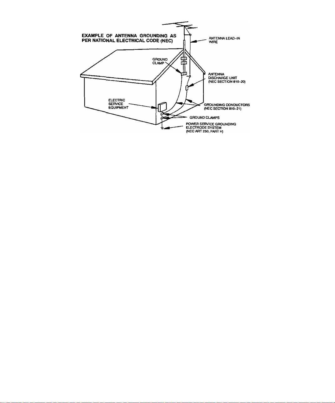
14. If an outside antenna is connected to the decoder equipment, be sure the antenna system is grounded so as to provide some
protection against voltage surges and built up static charges. In the U.S. Section 810 of the National Electrical Code, ANSI/
NFPA 70, and in Canada Part 1 of the Canadian Electrical Code provides information with respect to proper grounding of the
mast and supporting structure, grounding of the lead-in wire to an antenna discharge unit, size of grounding conductors,
location of antenna-discharge unit, connection to grounding electrodes, and requirements for the grounding electrode. See
Figure.
15. For added protection for this High Definition Television Decoder during a lightning storm, or when it is left unattended and
unused tor long periods of time, unplug it from the wall outlet and disconnect the antenna. This will prevent damage to the
decoder due to lightning and power-line surges.
16. An outside antenna system should not be located in the vicinity of overhead power lines or other electric light or power circuits,
or where it can fall into such power lines or circuits. When installing an outside antenna system extreme care should betaken to
keep from touching such power lines or circuits as contact with them might be fatal.
17. Unplug this High Definition Television Decoder from the wall outlet, and refer servicing to qualified service personnel under the
following conditions:
a. When the power cord or plug is damaged or frayed.
b. If liquid has been spilled into the High Definition Television Decoder.
c. If the High Definition Television Decoder has been exposed to rain or water.
d. If the High Definition Television Decoder does not operate normally by following the operating instructions. Adjust only
those controls that are covered by the operating instmctions as improper adjustment of other controls may result in
damage and will often require extensive work by a qualified technician to restore the High Definition Television Decoder
to normal operation.
e. If the High Definition Television Decoder has been dropped or the cabinet has been damaged.
f. When the High Definition Television Decoder exhibits a distinct change in performance - this indicates a need lor service,
18. Do not attempt to service this High Definition Television Decoder yourself as opening or removing covers may expose you to
dangerous voltage or other hazards. Refer all servicing to qualified service personnel.
19. When replacement parts are required, be sure the service technician has used replacement parts specified by the manufacturer
that have the same characteristics as the original part. Unauthorized substitutions may result in fire, electric shock, or other
hazards.
20. Upon completion of any service or repairs to this High Definition Television Decoder, ask the service technician to perform
routine safety checks to determine that the decoder is in safe operating condition.
21. WARNING: To prevent fire or shock hazard, do not expose this appliance to rain or moisture.
22. CAUTiON: TO PREVENT ELECTRIC SHOCK DO NOT USE THIS (POLARIZED) PLUG WITH A RECEPTACLE OR OTHER
OUTLET UNLESS THE BLADES CAN BE FULLY INSERTED TO PREVENT BLADE EXPOSURE.
NOTE: This equipment is designed to operate in the U.S.A. Canada and other countries where the broadcasting system and AC
house current is exactly the same as in the U.S.A. and Canada.
Page 6

ínformation on Digital Tblevision
Information on Digital Television
Digital Television
In April 1997, the Federal Communications Commission (FCC) announced that by
2006, all television broadcasting will be digital. However, television stations are
required to continue broadcasting regular TV signals along side the digital signals until
2006. Cable and satellite TV are not affected by the FCC ruling.
According to the FCC, digital broadcasting must be available from each of the four
major networks in each of the top ten markets, covering 30% of households by May
1999. By the end of 1999, it must be available in the top 30 markets, covering 50% of
households.
The FCC has allocated to each of the broadcasters a fixed amount of transmitting
“space” for digital programming. At the highest resolution. High Definition (HDTV),
one (1) or two (2) programs can be transmitted within this “space.” At lower
resolutions, Standard Definition (SDTV), several programs can be simultaneously
transmitted. Broadcasters will choose their own broadcast formats. For example,
they may choose to broadcast day programs in SDTV and night sports and movies in
HDTV. Digital Television (DTV) broadcasting will deliver crystal-clear pictures,
approaching the quality of 35mm movies, and compact disc (CD) sound.
HDTV (High Definition Television)
HDTV signal formats are 1080i (interlaced scan) and 720p (progressive scan). HDTV
provides the highest resolution picture and audio in either stereo or 5.1 channel
surround sound.
SDTV (Standard Definition Television)
SDTV signal formats are 480p and 480i. SDTV provides lower resolution, yet
presents a very sharp clear picture. Lower resolution allows broadcasters to transmit
multiple programs per channel.
Digital Broadcasting and Cable TV
The FCC has not mandated any standards for cable operators or satellite
broadcasters at the time this manual is printed. Some cable companies have
announced plans to introduce digital cable boxes into their markets. They may
choose, however, to use the digital capability to increase the number of channels
available or to provide data capability, such as high speed modem rather than transmit
HDTV programming.
Contact your local cable provider to determine if digital cable is available and
whether a cable box is needed for converting the signals.
Receiving Digital Broadcasts
Most households will be able to receive a digital broadcast by regular antenna with
VHF/UHF reception capability. However, like regular TV signals, it will depend on
location, terrain and environmental factors. Outdoor or attic antennas will generally be
more effective than a set-top antenna. For cable, check with your local cable provider
to find out if they will carry the DTV signal in your area.
4?
Page 7

Digital Picture Formats
DTV supports eighteen (18) Advanced Television Systems Committee (ATSC)* display
formats, which are variations of the four (4) following formats: 1080i (interlaced), 720p
(progressive), 480p (progressive) and 480i (interlaced). The larger the number, the
higher the resolution of the picture.
Interlaced Scan
For interlaced pictures, the odd number lines (picture information) are scanned,
creating field 1, then the even number lines are scanned, creating field 2. The two
fields are interlaced to provide the entire image (one frame). This process takes 1/30*'^
of a second and is invisible to the human eye.
Progressive Scan
For progressive pictures, all lines in an entire frame are scanned sequentially in i/60**^
of a second. With progressive scan, you will generally not see the thin black horizontal
scan lines (Venetian blind effect) associated with an interlaced picture.
Digital Audio
For all HDTV formats, Dolby** Digital surround sound (also commonly referred to as
AC-3** or DD 5.1) is the audio standard. AC-3 will provide CD-quality sound. The
system provides 3 separate audio channels for the front speakers (left, center, right), 2
channels for the rear surround sound speakers, plus one channel for subwoofer
sound. You will need an external audio system capable of decoding the AC-3
encoded sound to get the full surround sound effect. Otherwise, it can be connected
directly to your TV or audio system using only the stereo (left/right) audio outputs.
Note: The stereo audio outputs are Dolby Surround compatible. You can connect a Dolby
Information on Digital Television
Surround Pro Logic** decoder (not included) to the stereo audio outputs and receive
surround sound.
The ATSC is responsible for digital television development and standards.
‘‘Manufactured under license from Dolby Laboratories. “Dolby“, “AC-3”, “Pro Logic” and the double-D
symbol are trademarks of Dolby Laboratories. Confidential Unpublished Works. ©1992-1997 Dolby Labo
ratories, Inc. All rights reserved.
Page 8

Information on the Set-Top Box
Information on the Set-Top Box
Panasonic Digital Set-Top Box model TU-DST50
Current Conventional Televisions
Panasonic’s digital set-top box (STB) model TU-DST50 uses a Panasonic-developed
single chip which will allow current televisions (with AA/ inputs) to display digitally
broadcast programs. The STB, which receives only digital signals, has the ability to
convert the digital broadcast into National Television System Committee (NTSC)*
signals (480i) that a conventional television can display. The picture and sound
quality will be similar to small dish digital satellite systems today. Most conventional
televisions will not be able to display HDTV programs in their original format.
DTV-Compatible Televisions
The STB, by using component video connections, will allow DTV-compatible
televisions to produce pictures with incredible resolution. Component video consists
of three (3) primary color signals: red, green and blue that together convey all
necessary picture information. The three (3) component signals have been translated
into luminance (Y) and two color difference signals (Pq, Pr), each on a separate wire.
The STB, depending on the capabilities of the DTV-compatible television, will give you
the choice of HDTV or SDTV format.
Audio/Visual Features
The STB contains two vital links to the future of TV. The optical Dolby Digital (AC-3)
output connection provides the highest quality surround sound when attached to an
external AC-3 decoder/receiver. A digital interface connection allows the STB to be
attached to a Panasonic digital VHS (D-VHS) VCR.
DTV-Compatible Monitor/Receiver Capability
HDTV-Compatible (1080i/720p)
HDTV-compatible TV models process and display high definition output from the
Panasonic STB as a 1080i or 720p format. When DTV broadcasts are available in
your viewing area, your HDTV monitor/receiver will be compatible using the STB. It
will display the 16:9 wide screen aspect ratio format.
SDTV-Compatible (480p/480i)
SDTV-compatible TV models process and display standard definition output from the
Panasonic STB as a 480p or 480i format. When DTV broadcasts are available in your
viewing area, your SDTV monitor/receiver will be compatible using the STB. It will
display the incoming SDTV format.
*NTSC is the current television system used in the U.S. It uses analog (non-digital) signals.
Page 9

Congratulations
Your Panasonic digital set-top box (STB) features state-of-the-art technology for highquality picture and sound with complete audio/video output jacks for your home
theater system. DTV signals are displayed in either an interlaced or progressive
format, providing a clear, crisp picture. When connected to the STB, your HDTVcompatible monitor/receiver can display high-definition (HDTV) 1080i or 720p format
and standard definition (SDTV) 480p or 480i format. Your new STB is designed to
give you many years of enjoyment.
Customer Record
The model and serial number of this product are located on the back of the STB. You
should note the model and serial number in the space provided and retain as a
permanent record of your purchase. This will aid in identification in the event of theft
or loss. Product registration is available on-line at:
Care and Cleaning
Set-Top Box (Turn STB Off)
□ For STB, avoid excessive moisture and wipe dry.
□ Avoid bumping or scraping the STB.
Remote Control
n For Remote Control, use a soft cloth dampened with water or a mild detergent
Specifications
CONGRA TULA TfONS
www.prodreg.com\panasonic.
Model
Number
Serial
Number
solution. Avoid excessive moisture and wipe dry.
Do not use benzene, thinner or other petroleum based products.
Power Source 120V AC, 60Hz
Channel Capability
Digital Interface
Digital Audio Output AC-3 Fiber Optic
Video Output Jacks
Audio Output Jacks
S-Video Output Jacks S-Video (Y-C) Connector
DTV Output (Y, Pb, P„) 75 Ohm, Phono Jack Type
Specifications are subject to change without notice or obligation.
*The digital tuning system allows channel numbers up to 999 to be displayed. The total channel capability,
however, remains as stated.
1Vp.p, 75 Ohm, Phono Jack Type
VHF/UHF-2-69*
CATV-1-125*
To Panasonic D-VHS VCR only
0-2.0V rnns 4.7k Ohm
Page 10
Important Notes
Important Notes
STB Location
This unit can be used as part of an entertainment center. Consult your dealer for
available options.
n Avoid excessive sunlight or bright lights.
□ Keep away from excessive heat or moisture. Inadequate ventilation may cause internal
component failure.
O Fluorescent lighting may reduce Remote Control transmitting range.
Connecting Cables
Component video cables (Y, Pg, Pr) are provided for connection to a DTV-compatible
monitor/receiver. Shielded audio and video cables (not provided) should be used for all
other connections between components. For best results:
□ Use 75 Ohm coaxial shielded cables.
□ Check type of output and input connectors on your components.
□ Determine required cable lengths.
AC Power Supply Cord
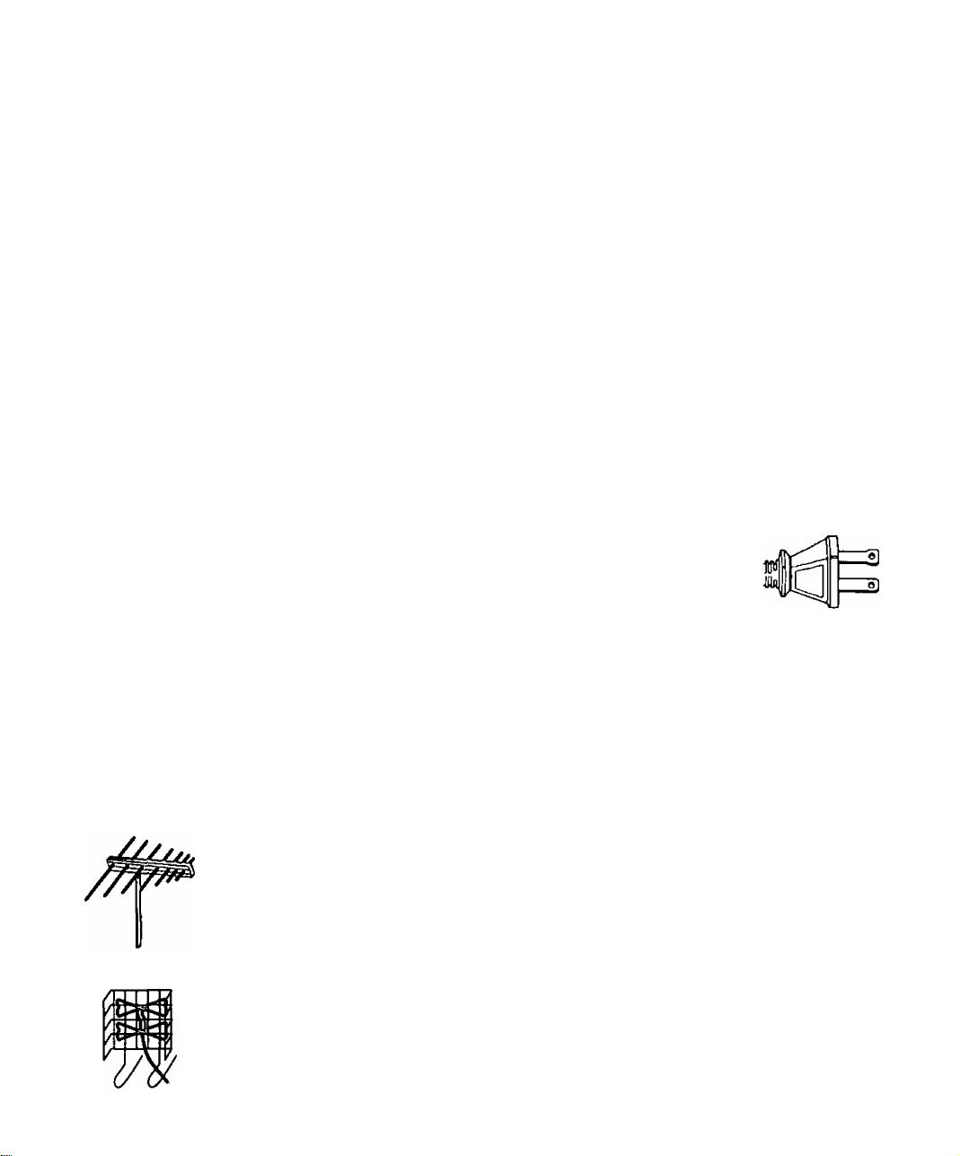
CAUTION: TO PREVENT ELECTRIC SHOCK, MATCH WIDE BLADE
OF PLUG TO WIDE SLOT OF AC OUTLET AND FULLY INSERT. DO
NOT USE A PLUG WITH A RECEPTACLE OR OTHER OUTLET
UNLESS THE BLADE CAN BE FULLY INSERTED TO PREVENT
BLADE EXPOSURE.
Polarized Plug
Antenna Installation and Orientation
In many areas, an indoor antenna can be used to received DTV signals. Certain
conditions, however, may create a situation where an outdoor antenna is required. Tall
buildings, large metal objects (e.g., a water tower) or hills may block the line-of-sight to
the TV station and interfere with DTV signal reception. Keep the following in mind
when installing and orienting your outdoor antenna. For additional information about
antennas, see the Consumer Electronics Manufacturing Association (СЕМА) website
at
www.cemacity.org or ask your local dealer.
□ Choose an antenna with directional receiving characteristics such as a Yagi, log periodic, or
reflector antenna. Avoid loop, wire bowtie, rabbit-ear and omni-directional antennas.
□ Use good grade 75 Ohm coax (round) cable to connect the antenna to the STB. Do not use
300 Ohm flat twin-lead cable.
□ Place the antenna away from large metal objects. If using an indoor antenna, remember
that aluminum siding and foil-covered insulation can greatly reduce the signal strength
inside your house.
□ Point the antenna in the direction of the TV station. Allow a 4-6 second delay in tuning.
Watch for a program to appear on the TV. If the signal indicator is “NOT FOUND” or if a
program comes and goes, try a slightly different position for the antenna. Slowly raising or
lowering the antenna by a few feet may help.
□ Avoid standing in front of the antenna while adjusting its position. Move a few feet to the
rear to avoid changing the signal characteristics.
□ If you are located in an area serviced by two (2) different DTV stations in different directions,
you may need an antenna rotator to receive signals from both stations.
Log Periodic
Reflector
0
iiu
ITT
Vagi
Page 11

Antenna/Cable Connection
For proper reception, an antenna or cable connection is required.
Antenna Connection
For proper reception of VHF/UHF channels, a directional antenna is required {see
previous page). For best reception, an outdoor antenna is recommended.
Procedure
□ Connect the antenna cable from your antenna.
□ Select ANTENNA, in the Roller Guide Menu™* SET UP Menu under Input (see Getting
Started section. Step 7).
Cable Connection
Before connecting your cable to the STB, contact your local cable provider and ask
the following questions:
• Is DTV available through your cable service?
• What type of cable do you have? Standard Cable TV Signals (Cable STD), Harmonic Related
Carrier (Cable HRC) or Incremental Related Carrier (Cable IRC).
• Do you need a separate cable box to receive DTV signals?
Procedure
□ Connect the cable wire provided by your local cable provider.
□ Select one of the following in the Roller Guide Menu^*^ SET UP Menu under Input (see
Getting Started section. Step 7).
• Cable STD - Standard Cable TV Signals
• Cable HRC - Harmonic Related Carrier
• Cable IRC - Incremental Related Carrier
Incoming Cable from
Home Antenna
75 Ohm VHF/UHF
on back oJ STB
Important Notes
Incoming Cable from
Cable Provider
a\
75 Ohm VHF/UHF
on back of STB
Note: The Panasonic DTV set-top box is able to receive DTV signals from your local cable
provider only if they are transmitted in the 8VSB modulation format approved by the
FCC for DTV transmission. Also, your cable provider may elect to transmit in the
8VSB format for only a limited period of time. Please contact your cable provider to
determine if 8VSB modulation is available.
* Roller Guide Menu is a trademark of Panasonic Consumer Electronics Company. U.S. Patent Pending.
Page 12
Front AND Rear View of the Set-Top Box
Front and Rear View of the Set-Top Box
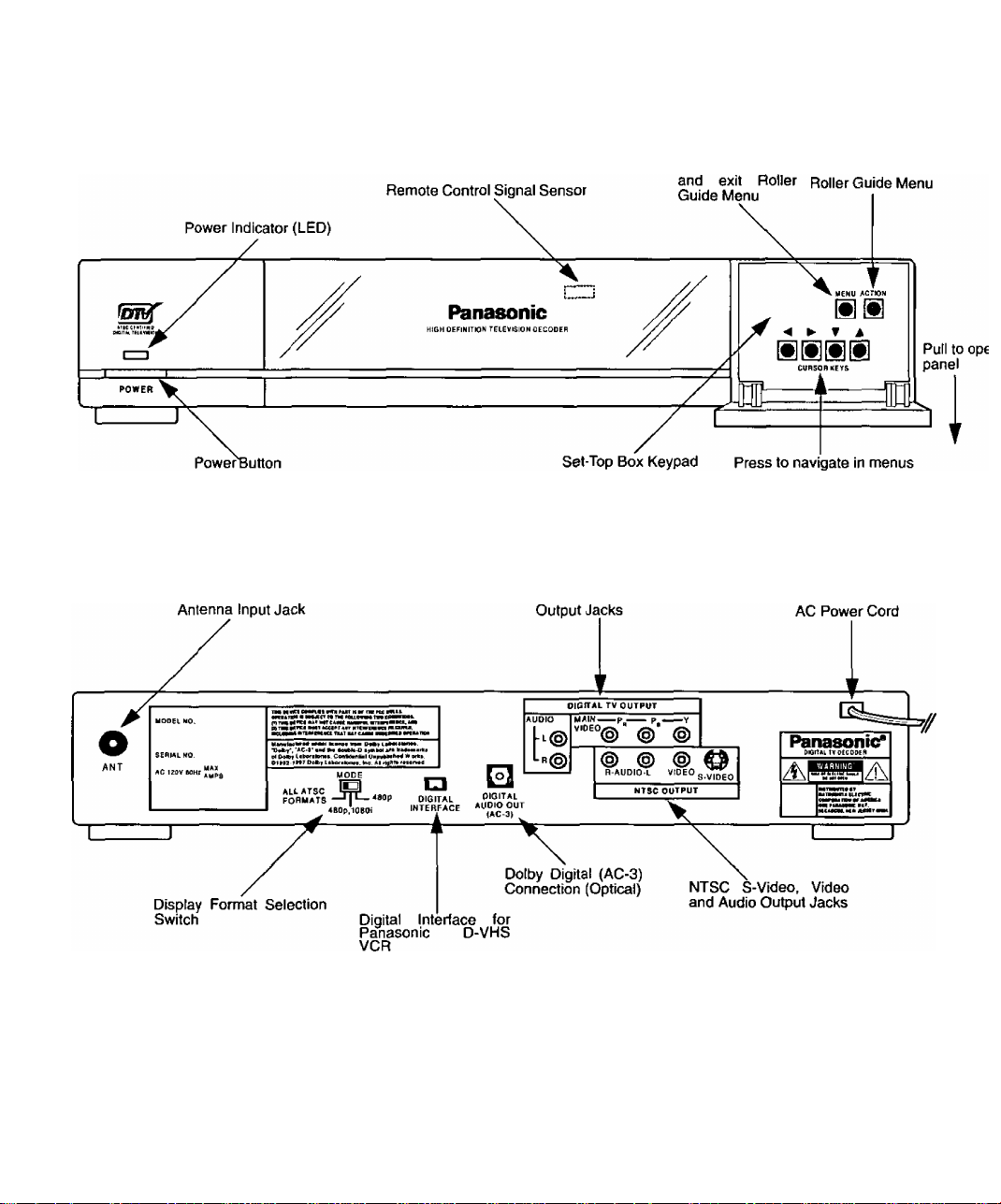
Front Panel
The following is a labeled illustration of the front panel of the STB.
Rear Panel
The following is a labeled illustration of the rear panel of the STB.
Press to access Press to select
"Ml
□TV Video and Audio
Note: Refer to the Table of Contents for page numbers.
*Such as CT-32XF55, CT-36DV60, PT-56WG80, PT-56WXF90 and other future models.
Page 13

Features of the Set-Top Box
Channel and Program Tuning
Channel and program tuning in digitai television is very different from current
conventional television. In DTV, up to six (6) multiple programs can exist within a
single 6 MHz channel. These programs behave as subchannels within the single
channel. When tuning to a channel, the STB will also tune to a program. Your STB
will indicate the channel and program through the on-screen Channel Banner display.
Channel and Program Tuning
The STB allows channel and program selection in the following ways:
□ Direct Tuning (0-9 keys) - Tunes directly to a channel or program.
□ Channel Up/Down Tuning (A or ▼ buttons) - Tunes to the next or previous available
channel or program.
□ Next Program Tuning (PROG button) - Tunes to the next program within a single 6 MHz
channel.
n Rapid Tuning (R-TUNE button) - Switches between the last two remembered channels or
programs.
Next Program Tuning
The PROG button on the remote control allows you to select programs within a single
6 MHz channel. Each time the PROG button is pressed, the STB will move to the next
available program within the channel.
Note: Only programs within the current 6 MHz channel can be selected using the PROG
button. If only one (1) program appears, it indicates only one (1) program Is available.
Features of the Set-Top Box
Channel Tuning Using Certain Panasonic Televisions
Some Panasonic television models* will automatically switch between using the STB
or the TV to tune channels.
DTV
When the remote control is in DTV mode and either the 0 - 9 numeric keypad or the
Channel Up/Down
DTV input. Channel tuning will be done through the STB.
TV
When the remote control is in TV mode and either the 0 ~ 9 numeric keypad or the
Channel Up/Down
TV input. Channel tuning will be done through the TV.
(A
or ▼ buttons) is used, the television will automatically switch to
(A
or
T
buttons) is used, the television will automatically switch to
iW
Page 14
Features of the Set-Top Box
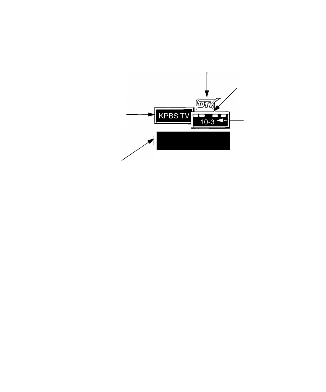
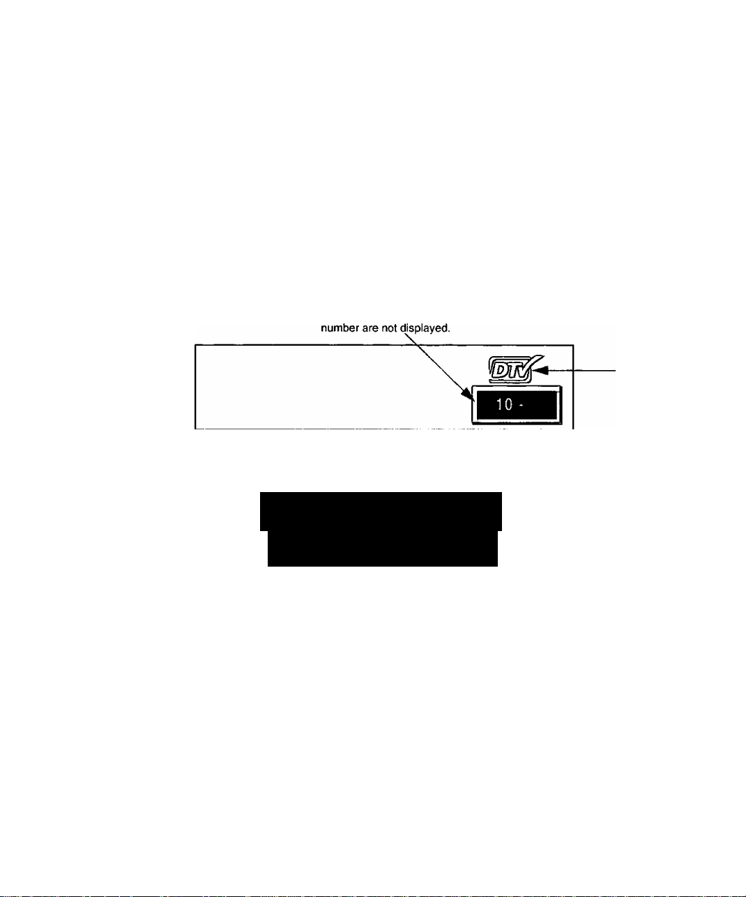
Channel Banner
The Channel Banner is used by all tuning methods to show you which channel and
program you are currently viewing or selecting. The banner will appear in the upper
right hand side of your TV screen.
Logo indicates
Digital TV
The bar indicates 5 possible
programs to choose from, with
the 3rd program selected.
Channel box displays
the Channel name*
DTV: 480-P Zoom
TV: A Sidebar
Format Into Banner displays the
DTV format and the aspect ratio of
both DTV and TV (NTSC) output of
the STB. The Format Info Banner
can be removed via the Display
Menu.
‘Channel box with Channel name may not appear in all situations.
Format
Aspect Ratio
Program box displays the
channel number followed
by the program number
Page 15
Unavailable Channel Selection
The unavailable channel selection screen is displayed when you select an unavailable
channel. The following is a list of some possible situations where an unavailable
channel selection may occur,
□ Tuning to a channel that is not transmitting any programs.
□ Tuning to a channel that stopped broadcasting programs.
□ The signal strength of the RF signal is insufficient to obtain consistent error free data.
Found or Not Found Input Signals
The unavailable channel selection screen also indicates whether the input signal is
found or not found.
□ Found signal (FOUND) - The tuner has found a signal, however, insufficient and/or
erroneous data is being received.
□ Not Found signal (NOT FOUND) - The tuner has not found a signal, therefore, data cannot
be received.
Displays the channel number.
A channel name and program
Features of the Set-Top Box
Logo indicates
Digital TV
Indicates an
unavailable
CHANNEL NOT AVAILABLE
INPUT SIGNAL: NOT FOUND
ID# 9E MR836520 47
STB Identification Number. Needed for
service calls. (The number shown is an
example only).
channel was
selected and
whether the
signal is
found or not
found.
Note: The screen remains displayed for 60 seconds, then is replaced by a blank screen.
Page 16
Features of the Set-Top Box
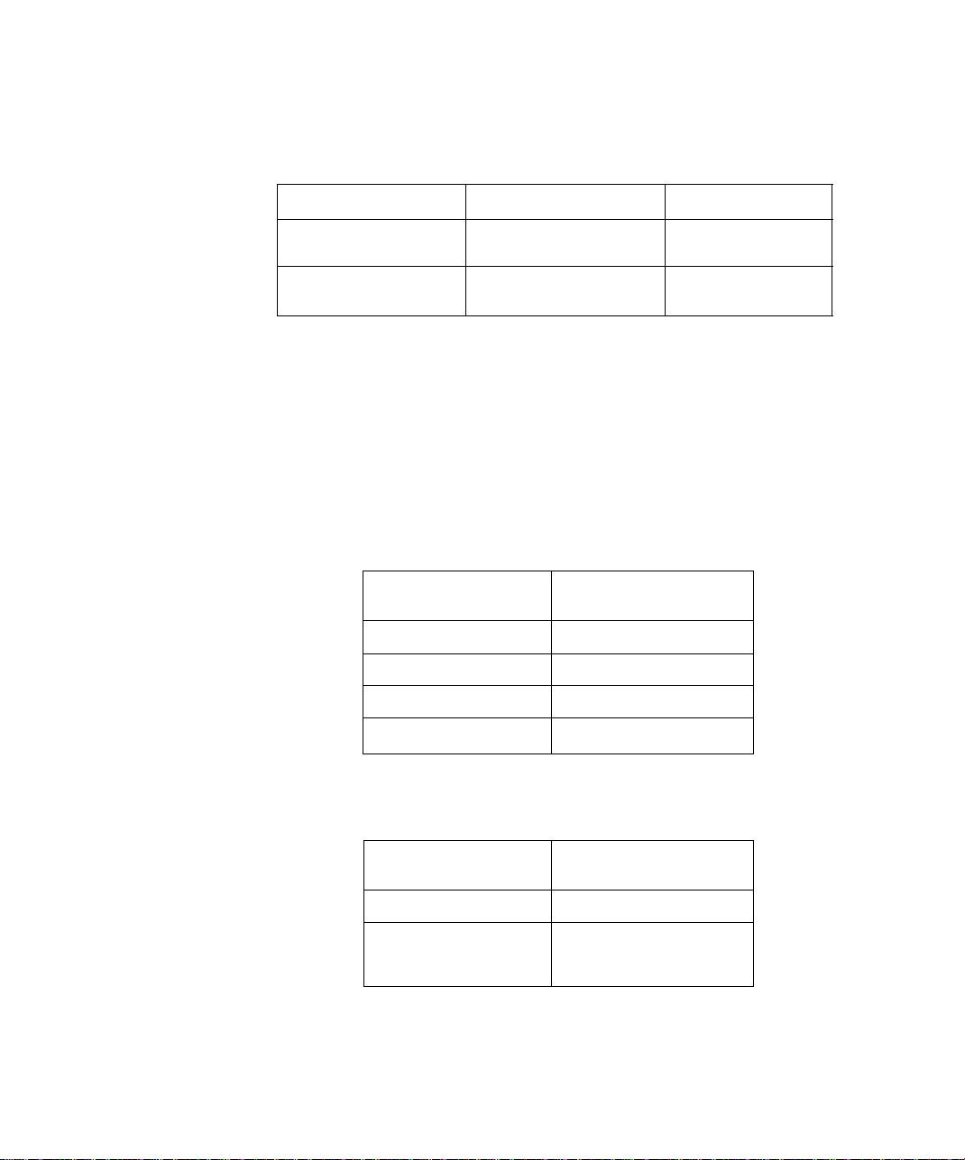
ATSC Display Formats
The STB converts all eighteen (18) ATSC display formats available in DTV into
viewable programming. The display formats are variations on the four (4) formats,
1080i, 720p, 480p and 480i. The following table shows the four (4) formats, their
resolutions and aspect ratios.
DTV Format Resolution Aspect Ratio
Display Format Selection
The STB allows you to choose a display format based on the capability of your TV or
monitor. To select the appropriate display format, use the MODE switch on the rear
panel of the STB. The MODE switch affects only the Y, Pq, Pr digital output. NTSC
output is not affected by the MODE switch.
Woie; This section applies to DTV-compatible televisions only.
All ATSC Formats
If your TV is capable of displaying all four (4) formats, 1080i, 720p, 480p and 4801,
then set the MODE switch to ALL ATSC FORMATS.
1080Ì
720p
480p
480i
Input Format
(from antenna/cable)
High Definition 16:9
Standard Definition 16:9 or 4:3
Output Format
(to TV)
1080Ì 1080Ì
720p 720p
480p
480i
480p
480i
480p, 10801
If your TV is capable of displaying 1080i and 480p formats, then set the MODE switch
to 480p, 1080i.
Input Format
(from antenna/cable)
1080Ì 1080Ì
720p
480p
480i
Output Format
(to TV)
480p
Page 17

480p
If your TV is capable of displaying 480p format only, then set the MODE switch to
480p.
Aspect Ratio Selection
The STB changes the normal aspect ratio {picture display shape) in response to the
source signal and monitor format of your TV. You can also change the aspect ratio for
your personal viewing preference. To select an aspect ratio, press the ASPECT
button on your remote control and the STB will cycle to the next available aspect ratio
choice. The following table shows the available aspect ratios.
Source Signal 16:9 4:3
16:9
Features of the Set-Top Box
Input Format Output Format
(from antenna/cable) (to TV)
1080Ì
720p
480p
480i
480p
Monitor Format
Full (No Scaling)
Full - Zoom - Letbox (Letterbox) -
Shrink
4:3
Full - Zoom - Sidebar - Expand
Full (No Scaling)
Full Aspect
16:9 or 4:3 picture will be displayed in the center of the viewing screen at full screen
width and height.
Zoom Aspect
The picture will be expanded uniformly (width and height) to fill the viewing screen.
The picture will be cropped, either horizontally or vertically to fit the viewing screen.
The cropped portion of the original picture will be lost from view.
Note: To properly view Closed Captioning, the STB may, in some cases, change the aspect
ratio from Zoom to Full.
Letbox (Letterbox) Aspect
Video formats with aspect ratios greater than 16:9 will be displayed at the proper
width, so no video information is lost. Bars will appear above and below the picture.
Shrink Aspect
The source aspect ratio will be maintained and the picture will shrink into full view on
the screen.
Sidebar Aspect
4:3 pictures will be viewed on a wide aspect TV screen with vertical bars on both sides
of the picture.
Expand Aspect
4:3 pictures will be viewed on a wide aspect TV screen with the picture digitally
“stretched” to fill the screen.
Note: See following page for illustrations of the various aspect ratios.
Page 18
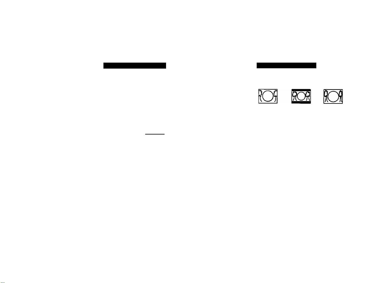
ASPECT RATIO FORMATS
3
3)
CO
O
'n
Source
Signal
16
The 16:9 and 4:3 pictures
represent the incx)nning
source signals received
by the STB.
16:9 MONITOR FORMAT
FULL
ZOOM
SIDEBAR EXPAND
i?Q^
These pictures show the different aspect ratios
available with a 16:9 monitor format.
• The top picture shows the 16:9 monitor
format available when the STB receives a
16:9 source signal.
• The bottom pictures show the 16:9 monitor
formats available when the STB receives a
4:3 source signal.
4:3 MONITOR FORMAT
FULL ZOOM LETTERBOX SHRINK
These pictures show the different aspect ratios
available with a 4:3 monitor format.
• The top pictures show the 4:3 monitor
formats available when the STB receives a
16:9 source signal.
• The bottom picture shows the 4:3 monitor
format available when the STB receives a
4:3 source signal.
Co
rn
3
*0
Q)
§
Page 19

Digital Interface for Panasonic D-VHS VCR
The digital interface on the STB allows the transfer high speed digital data between
devices. With the digital interface, there is no need to first convert digital data into
analog, eliminating the loss of data integrity. The digital interface on the STB allows
you to connect a Panasonic digital VHS (D-VHS) VCR only.
Digital VHS (D-VHS)
The D-VHS VCR records the digital data directly onto tape without digital-to-analog
conversion. The recorded data from the tape then needs to be decoded for playback
through the STB. The STB provides everything necessary to use a Panasonic D-VHS
VCR. The digital interface allows the STB to control the D-VHS VCR and even turn on
and simultaneously start recording through the TIMER feature.
Dolby Digital (AC-3) Audio
Dolby Digital (AC-3) 5.1 channel surround sound delivers CD-quality sound. AC-3
provides five discrete full-bandwidth channels for front left, front right, center, surround
left and surround right, plus a LFE (Low Frequency Effect) subwoofer channel.
External Dolby Decoder (Optional)
For a full Home Theater sound experience, an external AC-3 decoder and
multichannel amplifier must be connected to the STB.
Stereo Output
The internal decoder converts compressed audio data, up to 5.1 channels, into two
CD-quality stereo audio outputs, delivering stereo sound.
Note: The stereo audio outputs are Dolby Surround compatible. You can connect a Dolby
Surround Pro Logic decoder (not included) to the stereo audio outputs and receive
surround sound.
Fea tures of the Set-Top Box
W]
Page 20

Getting Started
Getting Started
step 1. Connect AC Power Cord
Plug the AC power cord into a grounded outlet. Do not turn on any devices until you
have finished making all necessary connections.
Step 2. Set-Top Box Connection to DTV-Compatible TV
Follow this diagram when connecting the STB to a DTV-compatible TV.
STB
NOTE: AUDIO CABLES NOT
INCLUDED
Procedure
• Connect video cables from the Y, Pg, Pr digital TV video output jacks on the STB to the Y,
Pg, Pr digital TV video input jacks on the DTV-compatible TV.
• Connect audio cables from the left and right digital TV audio output jacks on the STB to the
left and right digital TV audio input jacks on the TV.
Note: There are three video inputs, Y, Pg Pg. Separate component video inputs provide
DTV-COMPATIBLE TV SETUP
luminance and color difference signals.
Panasonic*
DIQITU. TV DECODER
WARNING B«
zi\f
eiTwewii uf crate
er AiuiE*
■auiCM, Mitt MM
Page 21

Step 2a. Set-Top Box Connection to Conventional TV
Follow this diagram when connecting the STB to a conventional TV.
CONVENTIONAL TV SETUP
Getting Started
NOTE: S-VIDEO. VIDEO AND AUDIO
CABLES NOT INtLUDED
Connect the
S-Video or
video cable.
See Note
below.
Procedure
• Connect video cable from the NTSC video output jack on the STB to the video input jack on
the TV.
OR
• Connect S-Video cable from the NTSC S-Video output jack on the STB to the S-Video input
jack on the TV.
Note: Connect either the S-Video or video input/output.
• S-Video will provide better picture quality.
• If both S-Video and video are connected, S-Video will override video.
• Connect audio cables from the left and right NTSC audio output jacks on the STB to the left
and right audio input jacks on the TV.
Step 3. Antenna/Cable Connection
Connect the antenna or cable wire to the ANT (Antenna) jack on the rear panel of the
STB.
Incoming signal
from antenna or
cable
Wl
Page 22

Getting Started
Step 3a. Digital TV/Standard TV Reception with DTV-Compatible TV
Follow this diagram if you have a DTV-compatible TV, no cable service and you want
to receive digital channels through the STB and standard channels through the TV. An
additional antenna may be required depending on which frequencies your current
antenna can receive.
NOTE; ANTENNA, SPLITTER, RF CABLES
AND AUDIO CABLES NOT INCLUDED
DTV-Compatible TV
1 [ klj )ouij—^ |—1
[audio
MAIN JTrf P.-Wp.-W''
VIDEO^ ^ ^
^L(g)
® © ® @
R-AODIO-L VIDEO
MTSC OUTPUT
Panasonic!”
EMGtTAL TV DECODER
WARMtiJC Mm
ggjeaHllH
A!
KflwntHT
uTtMHtr* (iicnc
CWVMATIM 0* AM MCA
DIGITAL TV/STANDARD TV RECEPTION WITH DTV-COMPATIBLE TV
SETUP
Procedure
• Connect the antehna cable to a splitter.
• Connect the splitter outputs to the STB and DTV-connpatible TV ANT (antenna) jacks using
standard RF cables with coaxial connectors.
• Follow directions in Getting Started section to connect the STB to a DTV-compatible TV.
~m\
Page 23

Step 3b. Digital TV/Standard TV Reception with Conventional TV
Follow this diagram if you have a conventional TV, no cable service and you want to
receive digital channels through the STB and standard channels through the TV. An
additional antenna may be required depending on which frequencies your current
antenna can receive.
NOTE; ANTENNA, SPLITTER, RF
CABLES, S-VIDEO, VIDEO AND AUDIO
CABLES NOT INCLUDED
Getting Started
Panasonic*
DlQltAL rvDtCOOEA
WARNING
m
lA
cxwejureee» iB*K*
□
DIGITAL TV/STANDARD TV RECEPTION WITH CONVENTIONAL TV
SETUP
Procedure
• Connect the antenna cable to the splitter.
• Connect the splitter outputs to the STB and TV ANT (antenna) jacks using standard RF
cables with coaxial connectors.
• Follow directions in Getting Started section to connect the STB to a conventional TV.
W\
Page 24

Getting Started
Step 3c. Digital TV/Cable Reception with DTV-Compatible TV
Follow this diagram if you have a DTV-compatible TV, cable service and you want to receive digital channels through the STB and cable channels through the cable box (or through the TV if you have no cable box).
Optional Cable Box
NOTE: ANTENNA. CABLE BOX. RF CABLE
AND AUDIO CABLES NOT INCLUDED
AUDIO
IGITJ
MAlN-m p -^P -Wy
|out)—t |—1
® ® ® @
R-AUDIO-L VIDEO
NTSC OUTPUT
Panasonic*
piOnAl TVgtCOOtA
A A
L
DIGITAL TV/CABLE RECEPTION WITH DTV-COMPATIBLE TV
SETUP
Procedure
• Connect the antenna cable to the STB ANT (antenna) jack.
• If using a cable box, connect the cable wire from the wall jack to the cable box ANT
(antenna) IN jack using a standard RF cable with a coaxial connector. Connect the cable
box ANT (antenna) OUT jack to the DTV-compatible TV ANT (antenna) IN jack using a RF
cable.
• If not using a cable box, connect the cable wire from the wall jack to the DTV-compatible TV
ANT (antenna) IN jack using a RF cable (not shown).
• Follow directions in Getting Started section to connect the STB to a DTV-compatible TV.
SS
Page 25

Step 3d. Digital TV/Cable Reception with Conventional TV
Follow this diagram if you have a conventional TV, cable service and you want to receive digital channels through the STB and cable channels through the cable box (or through the TV if you have no cable box).
Optional Cable Box
NOTE: ANTENNA, CABLE BOX, RF
CABLE, S-VIDEO, VIDEO AND AUDIO
CABLES NOT INCLUDED
Getting Started
DIGITAL TV/CABLE RECEPTION WITH CONVENTIONAL TV SETUP
Procedure
• Connect the antenna cable to the STB ANT (antenna) jack.
• If using a cable box, connect the cable wire from the wall jack to the cable box ANT
(antenna) IN jack using a standard RF cable with coaxial connector. Connect the cable box
ANT (antenna) OUT jack to the TV ANT (antenna) IN jack using a RF cable.
• If not using a cable box, connect the cable wire from the wall jack to the TV ANT (antenna)
IN jack using a RF cable (not shown).
• Follow directions in Getting Started section to connect the STB to a conventional TV.
~m\
Page 26

Getting Started
Step 3e. Digital 8VSB Cable/Analog Cable with DTV-Compatible TV
Follow this diagram if you have a DTV-compatible TV, cable service providing 8VSB
digital cable and you want to receive digital cable channels through the STB and
analog cable channels through the cable box (or through the TV if you have no cable
box).
Note: The STB is able to receive DTV signals from your local cable provider oniy if they are
transmitted in the 8VSB modulation format approved by the FCC for DTV
transmission. Also, your cable provider may elect to transmit in the 8VSB format for
only a limited period of time. Please contact your cable provider to determine if
8VSB modulation is available.
Analog Signal Optional Cable Box
NOTE: ANTENNA, SPLITTER, CABLE
BOX, RF CABLES AND AUDIO CABLES
NOT INCLUDED
8VSB Signal
Panasonici*
D«ITAl TV decoder
I
WARNING
DIGITAL 8VSB CABLE/ANALOG CABLE RECEPTION WITH
DTV-COMPATIBLE TV SETUP
Procedure
• Connect the cable wire from the wall jack to the splitter using a standard RF cable with
coaxial connectors.
• Connect one splitter output to the STB ANT (antenna) IN jack using a RF cable.
• If using a cable box, connect the other splitter output to the cable box ANT (antenna) IN
jack using a RF cable. Connect the cable box ANT (antenna) OUT jack to the DTV-
compatible TV ANT (antenna) IN jack using a RF cable.
• If not using a cable box, connect the other splitter output to the DTV-compatible TV ANT
(antenna) IN jack using a RF cable (not shown).
• Follow directions in Getting Started section to connect the STB to a DTV-compatible TV,
¥
lA
'M
Page 27

Step 3f. Digital 8VSB Cable/Analog Cable with Conventional TV
Follow this diagram if you have a conventional TV, cable service providing 8VSB
digital cable and you want to receive digital cable channels through the STB and
analog cable channels through the cable box (or through the TV if you have no cable
box).
Note: The STB is able to receive DTV signals from your local cable provider only if they are
transmitted in the 8VSB modulation format approved by the FCC for DTV
transmission. Also, your cable provider may elect to transmit in the 8VSB format for
only a limited period of time. Please contact your cable provider to determine if
8VSB modulation is available.
Analog Signal optional Cable Box
NOTE: ANTENNA, SPLITTER, CABLE BOX, RF
CABLES, S-VIDEO, VIDEO AND AUDIO
CABLES NOT INCLUDED
8VSB Signal
Getting Started
DIGITAL 8VSB CABLE/ANALOG CABLE RECEPTION WITH
CONVENTIONAL TV SETUP
Procedure
• Connect the cable wire from the wall jack to the splitter using a standard RF cable with
coaxial connectors.
• Connect one splitter output to the STB ANT (antenna) IN jack using a RF cable.
• If using a cable box, connect the other splitter output to the cable box ANT (antenna) IN
jack using a RF cable. Connect the cable box ANT (antenna) OUT jack to the TV ANT
(antenna) IN jack using a RF cable.
• If not using a cable box, connect the other splitter output to the TV ANT (antenna) IN jack
using a RF cable (not shown).
• Follow directions in Getting Started section to connect the STB to a conventional TV.
Page 28

Getting Started
Step 4. Turning STB On
Procedure
• Press the Remote Control DTV mode button
• Press the POWER button.
Note: TV should also be turned on.
Step 5. Switching to DTV Mode (Panasonic TV models)
Press the Remote Control TV/VIDEO button until DTV (VIDEO input) appears on the
TV screen.
Note: Non-Panasonic brand televisions require switching to the component video input.
Step 6. Roller Guide Menu™
Press the MENU button to display the Roller Guide Menu*. Press the A or 9 arrow
on the ACTION button to rotate the Roller Guide. Press the ^ arrow on the ACTION
button to exit the Roller Guide Menu.
Panasonic
"Ml
ROLLER GUIDE MENU SELECTIONS
m
DISPLAY
SET UP
a>sB5i
TIMER
AT for more features
Press ACTION to select.
Note: To exit the Roller Guide Menu, press the < arrow on the ACTION button or press the
MENU button.
Roller Guide Menu is a trademark of Panasonic Consumer Electronics Company. U.S.
Patent Pending.
Page 29

Step 6a. ACTION / Navigation Button
Press the ACTION button to select main menu items. Press the A or ^ arrows to
highlight sub menus. Press the ^ arrow to select features. Press the A or V arrows
to scroll through options within a feature. Press the ^ arrow to return to main menu
items.
Remote ACTION / Navigation Button
Getting Started
Note:
Be careful to press ACTION in the middle of the button. If you do not press in the
middle of the button, the arrow buttons may be activated.
Step 7. Antenna/Cable Mode
Select either Antenna or Cable mode, depending on the type of incoming signal you are using. Cable must be 8VSB format.
Procedure
□ In SET UP Menu, select INPUT to choose either ANTENNA or Cable.
n Press the ^ arrow, then the ^ and V arrows to select ANTENNA, Cable STD, Cable HRC
or Cable IRC.
• ANTENNA-VHF/UHF
• Cable STD - Standard Cable TV Signals
• Cable HRC - Harmonic Related Carrier
• Cable IRC - Incremental Related Carrier
Note: Contact your local cable provider if you are not sure which setting to use.
□ Press the ACTION button to make your selection.
□ Press the ^ arrow to exit back to Roller Guide.
Note: Whenever the antenna or cable mode is changed. Timer 1 and Timer 2 will revert back
to default settings.
W\
Page 30

Getting Started
Step 8. Programming Available Channels
YOU MUST PERFORM THE AUTOMATIC CHANNEL PROGRAMMING BEFORE
MANUALLY ADDING AND DELETING CHANNELS BECAUSE OF THE DIGITAL
TUNING SYSTEM USED BY THE STB. THIS METHOD WILL ENSURE THAT
EVERY AVAILABLE CHANNEL IS CAPTURED AND STORED INTO MEMORY.
Automatic Channel Programming
The STB will scan for all available channels and store them in memory. The scan will
normally take several minutes to complete.
Procedure
□ In SET UP Menu, select PROGRAM to choose AUTO to automatically scan and store all
channels with a signal.
• Press the ACTION button to cancel or exit back to SET UP Menu.
Note: As more digital channels become available in your area, the AUTO
feature must be selected to store the new digital channels into memory.
Manual Channel Programming
After programming all available channels, you can use the MANUAL feature to
selectively add or delete channels.
Procedure
n In SET UP Menu, select PROGRAM to choose MANUAL to manually add or delete
channels.
• Use the ^ arrow buttons and numeric keypad to select a channel.
• Use the ^ and ^ arrow buttons to add and delete channels.
• Press the ACTION button to exit back to SET UP Menu.
"Ml
The AUTO feature must be selected first to ensure that all
available channels are captured and stored into memory.
Page 31

Instaliation
Set-Top Box Connection to Panasonic D-VHS VCR
Follow this diagram when connecting the STB to a D-VHS VCR.
D-VHS VCR
T« Ti« «U»™* ri«<Wer<e*:
01 TMt ifmc« iAY «OT GJIMI JUIIDfM «mnMItCt. M»
onitimc« mT kgi^t mr imifiMKi mcimi,
■eLrt«»BTitPui«iu tHit an Glim «■»iMioo»ciiiTiei.
SEfltALNO.
AC 120V !
Antenna or cable wire
'AC-9' »H №• «*M-0 $)*MI If* vé4***i^
MOD£
ALLATSC ,,,
FORMATS —* I—<80p
48Cp.1Ce0è
NOTE: DIGITAL INTERFACE AND
AUDIO CABLES NOT INCLUDED
■■ n in ITA I
OlOlTAL
interface
STB
Installation
Panasonic*
CiCdAi IV OECODEH
^ARKm
M
\M
If
■unyMiTiii iitcnc
CWM4TVII 9f UflMCJl
OalJuiMeC viT.
ttCèiCM.Nv MimMii
DTV-Compatible TV I
PANASONIC D-VHS VCR SETUP
Procedure
• Connect digital interface cable from the digital interface output connection on the STB to
the digital interface input connection on the D-VHS VCR.
Note: The STB works with a Panasonic D-VHS VCR only.
• Follow directions in Getting Started section to connect the STB to a DTV-compatible TV.
W\
Page 32

Installation
Set-Top Box Connection to VCR/S-Video VCR
Follow this diagram when connecting the STB to a VCR or S-Video VCR.
Connect the S-Video or video
cable. See Note below.
VCR/S-VIdeo VCR
VCR/S-VIDEO VCR SETUP
NOTE: S-VIDEO, VIDEO AND AUDIO
CABLES NOT INCLUDED
Connect the
S-Video or
video cable.
See Note
below.
Panasonic*
DKilTAL TVDECOQEn
WARNING
\M
Wi
Procedure
• Connect video cable from the NTSC video output jack on the STB to the video input jack on
the VCR/S-Video VCR.
OR
• Connect S-Video cable from the NTSC S-Video output jack on the STB to the S-Video input
jack on the VCR/S-Video VCR.
• Connect audio cables from the left and right NTSC audio output jacks on the STB to the left
and right audio input jacks on the VCR/S-Video VCR.
• Connect video cable from video output jack on the VCR/S-Video VCR to video input jack on
TV.
OR
• Connect S-Video cable from S-Video output jack on the VCR/S-Video VCR to S-Video
input jack on TV.
• Connect audio cables from the left and right audio output jacks on the VCR/S-Video VCR to
the left and right audio input jacks on the TV.
Note: Connect either your S- Video or video input/output.
• S-Video will provide better picture quality.
• If both S-Video and video are connected, S-Video will override video.
Page 33

Optional Connections
Set-Top Box Connection to Dolby Digital AC-3 Decoder
Follow this diagram to connect the STB to a Dolby Digital AC-3 decoder.
Dolby Digital
AC-3 Decoder
r
DIGITAL
! 6-Channet Amplifier j [
i & Speakers i' 1
-------------------------------------------------------------------* 1
audio in
(AC-3)
P
jl
Optional Connecvons
DOLBY DIGITAL AC-3 DECODER SETUP
Procedure
• Connect Digital Audio cable from the Digital Audio Out connection on the STB to the Digital
Audio In connection on the Dolby Digital AC-3 decoder.
• Follow directions in Getting Started section to connect the STB to a DTV-compatible TV,
m
Page 34

Remote Control
Remote Control
ASPECT (Ratio) n
Select picture shape to match
signal and monitor format
[POWER
fPress to turn ON and OFF.
MENU
Press to access Roller Guide
Menu.
ACTION
Press to access main menu Items.
EPsaSii
r
0 amm o
L ^ J
VOLUME CHANNEL :
EXIT VCRREC GUIDE. ,- ■
MOVE SEARCH SIZE PIP
REW STOP PLAY FF
FREEZE PIP CHANNEL' SWAP
TVA/CR VCR'OBSCH PAUSE
O O €> ^
ci’Hn.cicsh: slow sitt.
LIGHT*
Press to light remote control for five
(5) seconds.
TVWIDEO
Press to select DTV, TV or Video
mode.
VCR DVD AUX RCVR
DTV TV CBL DBS
Press to select remote operation.
PROG (Program)
Press to select next program within
a channel.
‘0” - “9’
Press numeric keypad to select
any channel.
R-TUNE*
Press to switch to previously
viewed channel or program.
'M
O © © 1
R-TUNE- ■ —, R^^L I
Panasonic';^
EUR511154
*Tum the light OFF and ON by pressing
R-TUNE and RECALL, together.
CHANNEL
Press to select next channel or
program.
(RECALL*
Press to display time,
banner, and other options.
channel
Page 35

Remote Control Functional Key Chart
Remote Control Functional Key Chart
iSss
@yin^«r?l7t3ift
ALL COMPONENTS Turn com|>onents On and Off
[^nasfflsm
LIGHT
o
MUTE
o
TV/VIDEO
O
ASPECT
O
REMOTE CONTROL Illuminate buttons
TV RCVR CBL
ALL COMPONENTS Switch between component and TV
TV DTV
ALL COMPONENTS
TV DTV
Mute audio
Change picture shape to fit format:
Full - Normal picture shape {16:9
or 4:3)
Zoom - Expand picture uniformly
Letbox (Letterbox) - Black bars
above and below picture
Shrink - Picture will shrink to full
view
Sidebar/4:3 - 4:3 picture on wide
aspect screen with vertical bars
on both sides
Expand/Just • 4:3 picture digitally
“stretched” to fill wide aspect
screen
Component mode selection for
Remote Control
ACTION
^CTIO^
MENU
o
PROG
o
<3 O
TV
DTV
VCR DBS
CBL
DTV
DVD
DTV
K7
A
Up navigation
Down navigation
Left and right navigation
Exit Roiler Guide Menu
Seiect and adjust features
Roiier Guide Menu
Main menu selections
Menu
ENTER
Roiier Guide Menu
Menu
Select program within a channel
Wl
Page 36

Remote Control Functional Key Chart
Remote Control Functional Key Chart
rase?
VOLUME
a Q
CHANNEL
CD S
EXIT/GUIDE
CD
VCR REC
<E>
MOVE
REW
SEARCH
STOP
dD
SIZE
PLAY
CD
PIP
FF
FREEZE
TVA/CR
CD
OPEN/CLOSE
SWAP
PAUSE
cS)
STILL
PIP CHANNEL
VCR/DBS CH
SLOW
(^rasQaaiD
TV VCR DVD/LD AUX
CBL
RCVR CD AUX(TAPE)
ALL COMPONENTS
DBS Exit / Guide Menus
VCR
DBS
AUX (Cassette Deck)
TV
DVD/LD
CO Search Rewind
RCVR
VCR
AUX (Cassette Deck)
TV
VCR DVD/LD/CO
AUX (Cassette Deck)
TV
VCR DVD/LD/CD
AUX
TV PIP
DVD/LD
CD
RCVR
VCR
AUX (Cassette Deck)
TV
VCR
DVD/LD/CD
TV
DVD/CD/LD
VCR
AUX (Cassette Deck and Tape)
TV
VCR CBL DBS
RCVR
DVD
LD
CD
TV volume down and up
Cable volume down and up
Receiver volume down and up
Channel down
Channel up
Record
Move PIP
Skip / Search Rewind
Decrease surround
Rewind
PIP channel search
Stop
Change PIP size
Play
Skip/Search Fast Forward
Search Fast Forward
Increase Sound
Fast Forward
Freeze PIP
Switch between TV and VCR
Open / Close
Switch Main Picture and PIP
Still / Pause
Pause
PIP channel up / down
Channel up / down
Center channel sound up / down (-t/-)
Slow WSide A/B
Repeat / Random
'm\
Page 37

Remote Control Functional Key Chart
Remote Control Functional Key Chart
&3S
R-TUNE
o
RECALL
O
® @ ®
® ® ®
® ® ®
TV CBL DBS
DTV
DVD
LD
CD (AUX)
AUX (Cassette Deck)
TV VCR DVD/LD DBS
DTV
CD (AUX)
TV DTV VCR CABLE DBS
LD
CD (AUX)
RCVR
Previous channel
Previous channel or program
Title
AB repeat
Next disc
Deck A/B
On screen display
Set-top box on screen display
Time format
Selects channel
Selects code
Selects chapter
Selects track
Keys 1, 2, 3, and 4 selects AA/
Inputs, 5 = CD, 6 = Tuner, 7 =
Phono, 8 = Cassette Deck, 9 = Aux
[^miSCSSGD
®
Battery Installation
Incorrect installation can cause battery leakage and corrosion that will damage the
Remote Control.
Use two AA batteries:
Remove the battery cover by pushing in near the arrow and sliding the cover
back. (
Install batteries matching {+) and (-) polarity signs.
Replace the battery cover.
Precautions
• Replace batteries in pairs.
• Do not mix battery types (zinc carbon with alkaline).
• Do not recharge, short-circuit, heat, burn, or disassemble batteries.
Wl
Page 38

Special Remote Buttons
Special Remote Buttons
Aspect Ratio Selections
The ASPECT button changes the aspect ratio {picture display shape) in response to
the source signal and monitor format. You can also change the aspect ratio for your
personal viewing preference. Each time the ASPECT button is pressed, the STB will
cycle to the next available aspect ratio choice.
Full Aspect
16:9 or 4:3 picture will be displayed in the center of the viewing screen at full screen
width and height.
Zoom Aspect
The picture will be expanded uniformly (width and height) to fill the viewing screen.
The picture will be cropped, either horizontally or vertically to fit the viewing screen.
The cropped portion of the original picture will be lost from view.
Note: To property view Closed Captioning, the STB may, in some cases, change the aspect
ratio from Zoom to Full.
Letbox (Letterbox) Aspect
Video formats with aspect ratios greater than 16:9 will be displayed at the proper
width, so no video information is lost. Black bars will appear above and below the
picture
Shrink Aspect
The source aspect ratio will be maintained and the picture will shrink into full view on
the screen.
Sidebar Aspect
4:3 pictures will be viewed on a wide aspect TV screen with vertical bars on both sides
of the picture.
Expand Aspect
4:3 pictures will be viewed on a wide aspect TV screen with the picture digitally
“stretched” to fill the screen.
Note: See following page for illustrations of the various aspect ratios.
ASPECT
o
"Ml
Page 39

ASPECT RATIO FORMATS
Source
Signal
16
5DR 90R
O
The 16:9 and 4:3 pictures
represent the incoming
source signals received
by the STB.
ROfl IQ
16:9 MONITOR FORMAT
FULL
These pictures show the different aspect ratios
available with a 16:9 monitor format.
• The top picture shows the 16:9 monitor
• The bottom pictures show the 16:9 monitor
ZOOM
format available when the STB receives a
16:9 source signal.
formats available when the STB receives a
4:3 source signal.
SIDEBAR EXPAND
4:3 MONITOR FORMAT
FULL ZOOM LETTERBOX SHRINK
iOl liO^ RCffl OI
These pictures show the different aspect ratios
available with a 4:3 monitor format.
• The top pictures show the 4:3 monitor
formats available when the STB receives a
16:9 source signal.
• The bottom picture shows the 4:3 monitor
format available when the STB receives a
4:3 source signal.
CO
o
r*
§
o
rr|
CO
c:
o
Page 40

Special Remote Buttons
TVA/ideo
TV/VIDEO
O
The TV/VIDEO button allows you to select the mode of your TV. Each time the TV/
VIDEO button is pressed, the TV will cycle through Channel, Video 1, Video 2, Video 3
and DTV modes.
Note: Not all television models will display all the modes.
Menu
The MENU button allows you to access and exit the Roller Guide Menu. Each time
the MENU button is pressed, the Roller Guide will appear on and disappear from the
viewing screen.
Next Program ^
The PROG button allows you to select programs within a single 6 MHz channel. Each
time the PROG button is pressed, the STB will move to the next available program
within the channel.
Note: Only programs within the current 6 MHz channel can be selected using the PROG
button. If only one (1) program appears, it indicates only one (1) program is available.
Rapid Tuning
Recaii
The R-TUNE button quickly switches between two channels or programs. The STB
will attempt to immediately tune to the last channel or program in its memory. If
programs are no longer transmitting on the channel, the Unavailable Channel Screen
will display and the STB will automatically select the first program available on the
channel.
The RECALL button displays the Recall Screen for 6 seconds or until you press any
button (which automatically exits the Recall mode).
"Ml
Page 41

Component Codes
Component Codes
The Universal Remote Control is capable of operating many component brands after entering a code. Some components may not operate because memory is limited. The Universal Remote Control does not control all features in all models.
Codes for TV
(DdsoqS
Akai
Centurion
Daewoo
Emerson
Fisher
GE/Panasonic/
Quasar
GE/RCA 162
Hitachi
JVC 190
Magnavox
Marantz
110
112
120
141, 143, 144
150
101
180
210,212
220
dteBoa
Panasonic 100, 101, 102
Pioneer
ProScan
Quasar
Radioshack
RCA
Samsung 260
Sears/Toshiba 130
Sharp
Sony
Zenith/lnteq
222
230
101, 103
240
250, 255
265
270
290,291
Codes for Cable Box
(DEDai)
ABC 530
Archer
Cabieview
Citizen
Curtis
Diamond 530, 531,544
Eagle 541
Eastern
GC Brand
Gemini 522
General Instru-
ment/Jerrold
Hamlin
Hitachi
Macom
Memorex 542
Movietime 005, 544
Oak
Panasonic 120, 121, 132
Philips
Pioneer
Pulsar
531,544
005, 544
005, 522
130, 131
560
005,544
122, 360, 520, 521,522, 530, 531,532,
533
130, 350, 720, 730, 731, 900
003, 530
003, 004, 005
002,702, 710
006, 541,542
001,260
005, 544
UtEinil
Puser 544
Realistic 544
Regal
Regency 560
Rembrandt 005, 544, 702
Samsung
Scientific Atlanta 122, 130, 131
Simark
Sprucer
Stargate 005, 544
Teleview
Texscan
Tocom
Toshiba 004
Unika 531,544
Universal 522, 544
Videoway 006
Viewstar
Zenith
Zenith/Drake
Satellite
130, 350, 720, 730, 731,900
005
001,005
005, 121
001, 005
810
700, 701
541, 542
000, 280
000
©site
Page 42

Component Codes
s for VCR
dteni) ©séte
Admiral 200
Aiwa 137,160
Akai
Audio Dynamic Oil, 240
Bell & Howell 005, 013
Broksonic 081, 136
Canon 125,135
Citizen
Craig
Curtis Matties 130, 137, 300
Daewoo 001, 130, 250
DBX 010, Oil, 240
Dimensia 300
Emerson
Fisher 005, 007, 008, 009
Funai 081,136, 137
GE
Go Video 220, 512
Goldstar 006
Hitachi
Instant Replay 125, 130
J.C. Penney 000, 005, 010, Oil, 130, 240, 300
Jensen 240
JVC 010, Oil, 190, 240
Kenwood 006, 010, 011,240
LXI
Magnavox 125,130, 150
Marantz 010,011,240
Marta
Memorex 009, 130
MGA/Mitsubishi
Minolta 000, 300
Mont.Wards 006, 009, 200, 210. 290
Multitech 004, 137, 330
NEC 010,011,190, 240
Olympic 125, 130
014, 015,016,142
006
005,006, 141
003, 080, 081, 135, 136, 243, 250
130, 170,300
000, 125, 300
000, 005. 006, 007, 008, 009, 137
006
230, 241,242, 243, 330, 340
(UdoMI
Optimus 006, 100, 140,200
Orion
Panasonic 100, 101, 125, 130
Pentax 000,011,300
Philco 081, 125,130, 136, 137, 150
Philips
Pioneer 125
ProScan
Quasar
Radio Shack 005, 009, 130, 137, 170, 210, 241
RCA
Realistic
Samsung 002, 004, 220
Sansui 081, 136, 240, 520
Sanyo 005, 009
Scott
Sears 000, 005, 006, 007,008
Shaintom 050
Sharp
Signature 2000 137, 200
Singer 050
Sony
SV2000 137
Sylvania 125, 130, 137, 150
Symphonic 137
Tashiro
Tatung 010, 011,240
Teac
Technics 100, 101,125, 130
Teknika 130, 137
Toshiba 001,310
Vector Research
Yamaha 005,010, 011,240
Zenith 290
081, 136
125, 130, 150
000, 001,002, 125,130, 150, 300, 310
100, 101, 125, 130
000, 001, 002, 125,130, 150, 170, 300, 310
005,009, 130, 137,210, 241
001,002, 004, 009,081,136, 230, 241,
330, 340
200, 210
140, 141, 142
006
010, Oil, 137, 240
011
Page 43

Codes for CD
Component Codes
©jglilil
Carver
Denon 600
Fisher 405
Harman/Kardon 459, 460, 462
JVC 590, 591,670
Magnavox
Marantz
McIntosh 460
Optimus 430, 459
Panasonic 500, 501,530
Philips 550
dtejoil ©Site
Denon 100
Ferguson 110
Nordmende 110
Mitsubishi
Panasonic
Pioneer 120
RCA/ 110
550
550
550
150
100
©3él3
dteDD^l
Pioneer 430
Quasar
Sansui 432
Sanyo 405
Sharp
Sherwood
Sony 540
Technics
Victor
Yamaha 402, 403, 404
Codes for DVD
(Hiaiiii)
Saba 110
Sony
Thomson 110
Toshiba 130
Yamaha 100
Sony 270
Zenith/Inteq 290, 291
©aits
500, 501,530
600
459
500, 501,530
590, 591,670
©Site
140
EDgnil
Echo Star 110
GE
Hitachi
Panasonic
Philips 001,002
170
050
100
Codes for Cassette Deck
Panasonic 700,730
Technics 700, 730
Codes for DBS
©ails
P ri mestar
RCA 170
Sony 390
Toshiba 000
Uniden 001,002
©5l33
UteDOs]
©Séfe
391
Page 44

Component Codes
Codes for Laser Disc
dDSDail
Panasonic 200, 201,235,380
Pioneer
Sony 240, 241,242, 243
370
Codes for Receiver/Amplifier
©3i)3
Admiral 110
Aiwa 160, 161
Denon
Fisher 004
Garrard 055
Harman
Jensen 164
JVC 190,191
Kenwood 000,050
Magnavox 162
Marantz 151
McIntosh
Nakamichi
Onkyo 051,056
Write the code numbers for your components in the space provided below. This will serve as a reference when you need to reprogram your remote control.
CABLE Cable Box
200, 201,202
057, 150
058
031
VCR
Video Cassette
©DEDilil
Optimus 003, 162, 170, 171
Panasonic 100, 101, 130
Philips 150
Pioneer 030, 032
Quasar
RCA 003, 030, 162, 170, 171
Sansui 003, 053, 320
Sharp 200, 203
Sony
Soundesign 220
Teac 053,054, 055
Technics 100, 101,130
Victor
Yamaha 001,002
100, 101, 130
140
190, 191
RCVR
Receiver or Amplifier
Recorder
©333
LD
Laser Disc Player
DBS
Direct Broadcast
Satellite
Other Components
TV
Television
Other Components
CD
Compact Disc Player
Other Components
DVD
Digital Videodisc
Other Components
Page 45

Programming the Remote Control
The Universal Remote Control can be programmed to operate many manufacturers’
components using the component function buttons for VCR, DVD, AUX, RCVR, DTV,
TV, CBL, or DBS. Follow the procedures for programming your Remote Control with
and without codes for the component. Determine the manufacturer of the component
and look in the table for the code.
Note: Be careful to press ACTION in the middle of the button. If you do not press in the
middle of the button, the arrow buttons may be activated. This will interrupt your
programming.
Programming With Code
• Confirm that the external component is plugged in and is turned on.
• Turn the component off.
• Press the ACTION and POWER button, together, for at least 5 seconds. All
mode buttons will flash, then let go of the buttons.
• Press appropriate component button (VCR, CBL, etc.) on the Remote
Control. The pressed button will illuminate steadily. All other buttons will go
out.
• Enter the 3-digit component code using the Remote Control numeric keypad
{0-9 buttons). If a proper code was entered, the mode button wilt blink twice
and go out.
• Press the Remote Control POWER button to test the component. If the
procedure was successful, the component will turn on.
Programming the Remote Control
Programming Without Code
This procedure searches all codes and is called the “sequence method”.
• Confirm that the external component is plugged in and is turned on.
• Turn the component off.
• Press the ACTION and POWER button, together, for at least 5 seconds. All
mode buttons will flash, then let go of the button.
• Press appropriate component button on the Remote Control. The pressed
button will illuminate. All other buttons will go out.
• Press the ^ button to move forward to the next code. Press the ^ button to
move backward.
• Press the Remote Control POWER button to test the component. If the
procedure was successful, the component will turn on.
Note: Repeat the preceding two steps until the component code is found. It may take many attempts
before the correct code is found.
• After the code is found, press the ACTION button to store the code.
If the component does not operate with the Remote Control,
repeat the procedure using another code. (Some
brands have multiple codes.)
If an incorrect code is entered, or if the procedure takes longer
than 30 seconds, the programming will fail.
Page 46

Roller Guide Mewu™
Roller Guide Menu^^
Press the MENU button on the Remote Control to display the Roller Guide Menu.
Press the A or V arrow to rotate the Roller Guide. Press the <) arrow to exit the
Roller Guide Menu.
Panasonic
"^ROLLER GUIDE MENU SELECTIONS^
Note: To exit the Roller Guide Menu, press the C arrow on the ACTION button or press the
MENU button.
ACTION / Navigation Button
Press the ACTION button to select main menu items. Press the A or ^ arrows to
highlight sub menus. Press the ^ arrow to select features. Press the ^ or ^ arrows
to scroll through options within a feature. Press the ^ arrow to return to main menu
items.
DISPLAY
SET UP
iZXSBS
TIMER
AT for more features
Press ACTION to select.
Remote ACTION / Navigation Button
"S'
<3^ACT^[>
'M
Note: Be careful to press ACTION in the middle of the button. If you do not press in the
middle of the button, the arrow buttons may be activated.
Page 47

Roller Guide Feature Chart
Roller Guide Feature Chart
Roller Guide Feature Chart
[SMm
SET UP
INPUT
PROGRAM
CLOCK
leg MODE
(Closed Captioned)
Descrirtion.
SETUP
n MODE - Select one of the following:
• ANTENNA (default setting) - VHF/UHF
• Cable STD - Standard Cable TV
Signals
• Cable HRC - Harmonic Related
Carrier
• Cable IRC - Incremental Related
Carrier
Note: Contact your local cable provider If you
are not sure which setting to use.
□ AUTO - Automatically program channels
having a signal into memory.
□ MANUAL - Manually add or delete
channels from memory.
CLOCK - Set time for the DTV system
clock. TIME will display on screen after
pressing POWER button, RECALL button,
or changing channels. (Clock must be set
to use Timer features).
CC (If available)
• CC1-CC4 for closed captioning
services.
• T1-T4 for text services.
MONITOR
BACKDROP
INFO
DISPLAY
TYPE
• 16:9 (default setting) for HDTV wide
screen.
• 4:3 for SDTV.
BACKDROP
• Black (not recommended)
• Gray (default setting)
INFO - Select ON or OFF for the Format
Info Banner.
Page 48

Roller Guide Feature Chart
Roller Guide Feature Chart (Cont)
(Maw
&
CONTROLS
MINIMIZE
V)
TIMER
TIMER 1
TIMER 2
DESeRIRTlON.
D-VHS
CONTROLS - Select to display D-VHS
Control Panel buttons and status box.
MINIMIZE - Select to minimize D-VHS
Control Panel buttons to a title bar.
TIMER
□ DAY - Select the day of the week to
activate timer.
• START - Select time for timer to start.
• STOP - Select time for timer to stop.
□ CHANNEL - Select the channel for STB to
tune to at appropriate time.
□ MODE - Select one of the following:
• OFF (default setting) to disable timer.
• VIEW to turn on STB only. (Must turn
TV on to view the event).
• RECORD to turn on STB and start DVHS recording mode.
Note: Whenever the antenna or cable mode
is changed, Timer 1 and Timer 2 will
revert back to default settings.
~m\
Page 49

Special Features
SETUP
Antenna/Cable Mode
Select either Antenna or Cable mode, depending on the type of incoming signal you
are using. Cable must be 8VSB format.
Procedure
□ In SET UP Menu, select INPUT to choose either ANTENNA or Cable.
□ Press the ^ arrow, then the A and V arrows to select ANTENNA, Cable STD, Cable HRC
Note: Contact your local cable provider if you are not sure which setting to use.
□ Press the ACTION button to make your selection.
□ Press the ^ arrow to exit back to Roller Guide.
Note: Whenever the antenna or cable mode is changed, Timer 1 and Timer 2 will revert back
Special Features
or Cable IRC.
• ANTENNA - VHF/UHF
• Cable STD - Standard Cable TV Signals
• Cable HRC - Harmonic Related Carrier
• Cable IRC - Incremental Related Carrier
to default settings.
Programming Available Channels
You must perform the automatic channel programming before manually adding and
deleting channels because of the digital tuning system used by the STB. This method
will ensure that every available channel will be captured and stored into memory.
Automatic Channel Programming
The STB will scan for all available channels and store them in memory. The scan will
normally take several minutes to complete.
Procedure
□ In SET UP Menu, select PROGRAM to choose AUTO to automatically scan and store all
channels with a signal.
• Press the ACTION button to cancel or exit back to SET UP Menu.
Note: As more digital channels become available in your area, the AUTO
feature must be selected to store the new digital channels into memory.
Page 50

Special Features
Manual Channel Programming
After programming all available channels, you can use the MANUAL feature to selectively add or delete channels.
Procedure
□ In SET UP Menu, select PROGRAM to choose MANUAL to manually add or delete
channels.
• Use the A, V arrow buttons and numeric keypad to select a channel.
• Use the ^ and ^ arrow buttons to add and delete channels.
• Press the ACTION button to exit back to SET UP Menu.
AUTO MANUAL
The AUTO feature must be selected first to ensure that all
available channels are captured and stored into memory.
Page 51

Special Features
ICCI (Closed Captioned)
The STB contains a built-in decoder that is capable of providing a visual display of the
audio portion. The program viewed must provide Closed Captioning (CC) for the
television to display it. CC is displayed in the form of text across the screen (white or
colored letters on black background). It allows the viewer to read the dialogue of a
television program or other information.
ICCI Mode
□ In SET UP Menu, select CC (Closed Caption) MODE
□ Press the V arrow to select ICCI MODE
□ Press the ^ arrow, then the A or V arrow to select NONE, CC1, CC2, CC3, CC4, T1, T2,
T3 or T4.
• CAPTION OFF - Use when Closed Caption is not desired.
• CAPTION CC1 - For video related information that can be displayed (up to 4 lines of script
on the screen, where it does not obstruct relevant parts of the picture). Script can be in any
language.
• CAPTION CC2 - Another mode used for video related information.
• CAPTION CC3 and CC4 - Other modes used for video related information.
• TEXT T1 ' Blanks out a large portion of the picture on the television screen, and displays
program guide or any other information currently being transmitted.
• TEXT T2, T3 & T4 - Other Modes that display information and blank out a large portion of
the picture on the television screen.
n Press ACTION once, then the O arrow to return to Roller Guide,
Note: To properly view Closed Captioning, the STB may, in some cases, change the aspect
ratio from Zoom to Full.
Page 52

Special Features
D-VHS
D-VHS Control Panel
The STB allows you to control a Panasonic D-VHS VCR through the digital interface.
The on-screen panel of D-VHS control buttons in the D-VHS menu lets you record and
playback digital programs.
Note: The STB must be on when D-VHS VCR is recording.
Control Panel
□ In D-VHS Menu, select Controls.
n Use ^and V arrow buttons to select a command,
n Press the ACTION button to execute the command.
□ Press C arrow twice to exit to Roller Guide.
Rewinding I
01:00:00
LU
___
DEBS
Controls 1 [gfegftnffiipl [
i J EH® mss> : w
^nirirn
l5iBga[b gKsgsessfljglk
Note: A status box will appear in the upper right corner describing the command being
executed.
Minimizing Control Panel
The STB also allows you to minimize the D-VHS control panel into a title bar, to
reduce the portion of the picture blocked by the control panel.
Title Bar
□ In D-VHS Menu, select Minimize.
□ Press the ACTION button to minimize the control panel into a title bar.
n Use C and ^ arrow buttons to select a command.
n Press the ACTION button to execute the command.
□ Select ▲, then press the ACTION button to maximize the control panel.
□ Press <J arrow once to exit to Roller Guide.
[^-irTnn^irrnirfrjr^l I
w\
Note: The title bar will appear at the bottom of the screen.
Page 53

___________________________________________________ Special Features
D-VHS Status Messages
The STB will report status information about the D-VHS in the status box. The following table is a list of possible status messages.
Command or Event
REW
STOP
FF
PLAY
PAUSE
REC
D-VHS empty
Play: Fast Forward
Play: Rewind
Play: Fast Rewind
Tape is not recordable
Analog tape loaded
D-VHS not connected to DTV
D-VHS reported error
D-VHS is powered OFF
Status Message
Rewinding
Stop
Fast Fonvarding
Playing
Pause
Recording
No Cassette
Forward Searching
Reverse Searching
Reverse Searching
Not Recordable
Analog Tape
Not present
Error
Powered Off
§0
Page 54

Special Features
TIMER
Timer 1 and Timer 2
The STB contains two timers that are capable of turning the STB on and off at selected times, on selected channels and on selected days. You can also set your STB to simultaneously turn your D-VHS on to recording mode.
Timer Set up
□ In TIMER Menu, press the A or ^ arrow to select either TIMER 1 or TIMER 2
Note: TIME must be entered in CLOCK to operate TIMER features.
□ Press the ^ arrow twice, then the A or V arrow to select the day.
n Press the ACTION button to move to the first time field.
□ Press the A or V arrow to select the hour, then the & arrow to move to the minutes.
□ Press the or V arrow to select the minutes, then press the ACTION button to move to
the next time field.
□ Press the A or V arrow to select the hour, then the ^ arrow to move to the minutes.
□ Press the A or ^ arrow to select the minutes, then press the ACTION button.
n Press the ^ arrow, then the A or ^ arrow to select the channel.
□ Press the ACTION button.
□ Press the ^ arrow once, then the ^ arrow once.
□ Press the A or ^ arrow to select the mode.
• OFF - Disables the timer.
• VIEW - Turns on STB only. (Must turn TV on to view the event).
• RECORD - Turns on STB and starts D-VHS recording mode.
Note: All data fields must be entered prior to selecting a mode.
□ Press ACTION once, then the C arrow twice, to return to Roller Guide
■Ml
Note:
Times cannot overlap between the timers. The first entered timer (either Timer 1 or
Timer 2) will override the second entered timer.
TIME R Activation
The TIMER is active when the STB is OFF or ON.
The STB will switch to the selected channel at the
selected time set in the TIMER.
Page 55

Special Features
Timer Error Messages
The STB will scan the tinner data fields and notify you of any problems before letting
you set the Mode. The following is a table of possible error messages.
Error Condition
The system time was not set NOTICE: Clock must be set
No data is entered in any of the timer data
fields
The day of the week was not entered NOTICE: Day must be entered
The start time was not entered
The stop time was not entered
The channel number was not entered
The day conflicts with the other timer
The start time conflicts with the other timer
The stop time conflicts with the other timer NOTICE: Stop conflicts with Timer 2 (or 1)
The stop time conflicts with start time
NOTICE: Timer 1 (or 2) data must be
entered
NOTICE: Start time must be entered
NOTICE: Stop time must be entered
NOTICE: Ch number must be entered.
NOTICE: Day conflicts with Timer 2 (or 1)
NOTICE: Start conflicts with Timer 2 (or 1)
NOTICE: Stop conflicts with start time
Error Message
"Ml
Page 56

Troubleshooting
Troubleshooting
Before requesting service for this unit, check the table below for a possible cause of the problem you are
experiencing. Some simple checks or a minor adjustment on your part may eliminate the problem and
restore proper operation.
If you are in doubt about some of the check points, or if the remedies indicated in the table do not solve the
problem, consult your dealer or call 1-888-VIEW-PTV (843-9788) for assistance.
Symptom Remedy
No power Check that the AC power plug is securely plugged into the power outlet.
•Check that equipment is connected properly.
No reception
No digital cable
No picture
•Check that antenna is properly installed and oriented.
•Check that the antenna or cable wire is connected properly.
•Make sure the proper mode {antenna or cable) is selected.
•Make sure your local cable provider is transmitting in 8VSB modulation
format.
•Make sure the proper cable mode is selected.
•Check that equipment is connected properly.
•Check if the channel is available.
•Rerun the Automatic Channel Programming to make sure all available
channels are captured and stored into memory.
Available channels are missing
Picture is distorted
Zoom aspect cannot be selected
No sound Check that equipment is connected properly.
The remote control is not responding
The remote control is operational, but
the STB is not responding
The remote control is operational, but
other component(s) are not responding
The ACTION button is not responding
•Rerun the Automatic Channel Programming to make sure all available
channels are captured and stored into memory.
•Make sure the proper display format is selected.
•Make sure the proper aspect ratio is selected.
•Make sure the Closed Caption feature is turned off.
•Make sure the remote control is in DTV mode.
•Check that the batteries are installed with the correct polarities {+ and -)•
•The batteries are depleted: Replace them with new ones.
•Point the remote control unit at the remote control sensor and operate.
•Operate the remote control unit at a distance of not more than 23 feet (7
meters) from the remote control sensor.
•Remove any obstacles between the remote control unit and remote
control sensor.
•Check that the AC power plug is securely plugged into the power outlet.
•Make sure the STB is on.
•Make sure the remote control is in DTV mode.
•Check that the AC power plug is securely plugged into the power outlet.
•Make sure the component(s) are on.
•Reprogram the remote control to make sure it is programmed properly
to operate the component(s).
•Make sure the remote control is in the proper component mode (i.e. TV,
CBL, RCVR, etc.).
•Make sure to press ACTION in the middle of the button.
•Make sure the remote control is in DTV mode.
~M]
Page 57

Symptom
Troubleshooting
Remedy
No key operation (by the unit and/or
the remote control) is effective.
D-VHS VCR is not responding
D-VHS VCR does not record Make sure STB is on
VCR/S-Video VCR is not responding
AC-3 decoder is not responding
Timer does not work
Set the POWER button to OFF and then back to ON. Alternatively, turn
off the power, disconnect the power plug and then reconnect it. (The STB
may not be operating properly due to lightning, static electricity or some
other extemai factor).
•Check that the AC power plug is securely plugged into the power outlet.
•Check that equipment is connected properly.
•Make sure it is a Panasonic D-VHS VCR.
•Check that the AC power plug is securely plugged into the power outlet,
•Check that equipment is connected properly.
•Make sure remote control is in VCR mode.
•Check that the AC power plug is securely plugged into the power outlet.
•Check that equipment is connected properly.
•Make sure the clock is set.
•Check to see whether the timers have overlapping times programmed.
•Check if the timer did not reset to default settings (antenna/cable mode
was changed).
Product Service
Do not attempt to remove the cover or repair
the unit yourself. Refer servicing to qualified
personnel only.
Product Information
For product service, product information or
assistance with product operation, consult your
dealer or call 1-888-VIEW-PTV (843-9788).
Please have your Set-Top Box Identification
Number (ID#) available when you call. The
ID# is displayed on your TV screen when the
STB is tuned to any unavailable channel.
If you ship the product
Carefully pack and send it prepaid,
adequately insured and preferably in the
original carton. Attach a postage-affixed
letter, detailing the complaint, to the outside of
the carton. DO NOT send the product to the
Executive or Regional Sates offices. They are
NOT equipped to make repairs.
For service assistance, please call:
1-888-VIEW-PTV (843-9788).
Page 58

 Loading...