

Panasonic TH-65VX300ER Schematic
Order Number PCZ1111138CE
High Definition Plasma Display
Model No. TH-65VX300ER
GPF14DMONV Chassis
TABLE OF CONTENTS
1 Safety Precautions ----------------------------------------------- 3
1.1. General Guidelines---------------------------------------- 3
1.2. Touch-Current Check ------------------------------------- 3
2 Warning-------------------------------------------------------------- 4
2.1. Prevention of Electrostatic Discharge (ESD)
to Electrostatically Sensitive (ES) Devices---------- 4
2.2. About lead free solder (PbF)---------------------------- 5
3 Service Navigation ----------------------------------------------- 6
3.1. Service Hint ------------------------------------------------- 6
3.2. Applicable signals ----------------------------------------- 7
4 Specifications ----------------------------------------------------- 8
5 Operating Instructions------------------------------------------ 9
6 Service Mode -----------------------------------------------------10
6.1. CAT (Computer Aided Test) mode -------------------10
6.2. IIC mode structure (following items value is
sample data) -----------------------------------------------14
7 Troubleshooting Guide ----------------------------------------15
7.1. Self Check--------------------------------------------------15
7.2. No Power ---------------------------------------------------17
PAG E PAG E
7.3. No Picture-------------------------------------------------- 17
7.4. Local screen failure-------------------------------------- 18
8 Service Fixture & Tools --------------------------------------- 19
8.1. SC jig -------------------------------------------------------- 19
9 Disassembly and Assembly Instructions--------------- 20
9.1. Removal of Rear Cover -------------------------------- 20
9.2. Removal of Slot Block ---------------------------------- 20
9.3. Removal of DS-Board----------------------------------- 20
9.4. Removal of D-Board------------------------------------- 20
9.5. Removal of HX-Board----------------------------------- 20
9.6. Removal of A-Board------------------------------------- 21
9.7. Removal of Fan------------------------------------------- 21
9.8. Removal of P(MAIN)-Board --------------------------- 22
9.9. Removal of P(SUS)-Board----------------------------- 22
9.10. Removal of AC Inlet Assy------------------------------ 22
9.11. Removal of H3-Board ----------------------------------- 22
9.12. Removal of SU-Board and SD-Board--------------- 23
9.13. Removal of SC-Board----------------------------------- 23
9.14. Removal of SS-Board----------------------------------- 24
© Panasonic Corporation 2011
Unauthorized copying and distribution is a violation
of law.

TH-65VX300ER
9.15. Removal of SS2-Board ---------------------------------24
9.16. Removal of C1-Board ----------------------------------- 24
9.17. Removal of C2-Board ----------------------------------- 25
9.18. Removal of C3-Board ----------------------------------- 25
9.19. Removal of S1-Board -----------------------------------25
9.20. Removal of Front Glass, V, V1, V2-Board and
Cabinet Assy ---------------------------------------------- 26
9.21. Removal of Plasma Display Panel-------------------27
10 Measurements and Adjustments -------------------------- 32
10.1. Adjustment ------------------------------------------------- 32
10.2. Adjustment ------------------------------------------------- 33
11 Block D iagra m --------------------------------------------------- 37
11.1. Main Block Diagram ------------------------------------ 37
11.2. Block (1 of 6) Diagram ---------------------------------- 38
11.3. Block (2 of 6) Diagram ---------------------------------- 39
11.4. Block (3 of 6) Diagram ---------------------------------- 40
11.5. Block (4 of 6) Diagram ---------------------------------- 41
11.6. Block (5 of 6) Diagram ---------------------------------- 42
11.7. Block (6 of 6) Diagram ---------------------------------- 43
12 Wiring Connection Diagram--------------------------------- 45
12.1. Wiring (1) --------------------------------------------------- 45
12.2. Wiring (2) --------------------------------------------------- 46
13 Schematic Diagram
14 Printed Circuit Board
15 Exploded View and Replacement Parts List
15.1. Exploded View
15.2. Electrical Replacement Parts List
2
TH-65VX300ER
1 Safety Precautions
1.1. General Guidelines
1. When conducting repairs and servicing, do not attempt to modify the equipment, its parts or its materials.
2. When wiring units (with cables, flexible cables or lead wires) are supplied as repair parts and only one wire or some of the
wires have been broken or disconnected, do not attempt to repair or re-wire the units. Replace the entire wiring unit instead.
3. When conducting repairs and servicing, do not twist the Fasten connectors but plug them straight in or unplug them straight
out.
4. When servicing, observe the original lead dress.If a short circuit is found, replace all parts which have been overheated or
damaged by the short circuit.
5. After servicing, see to it that all the protective devices such as insulation barriers, insulation papers shields are properly
installed.
6. After servicing, make the following leakage current checks to prevent the customer from being exposed to shock hazards.
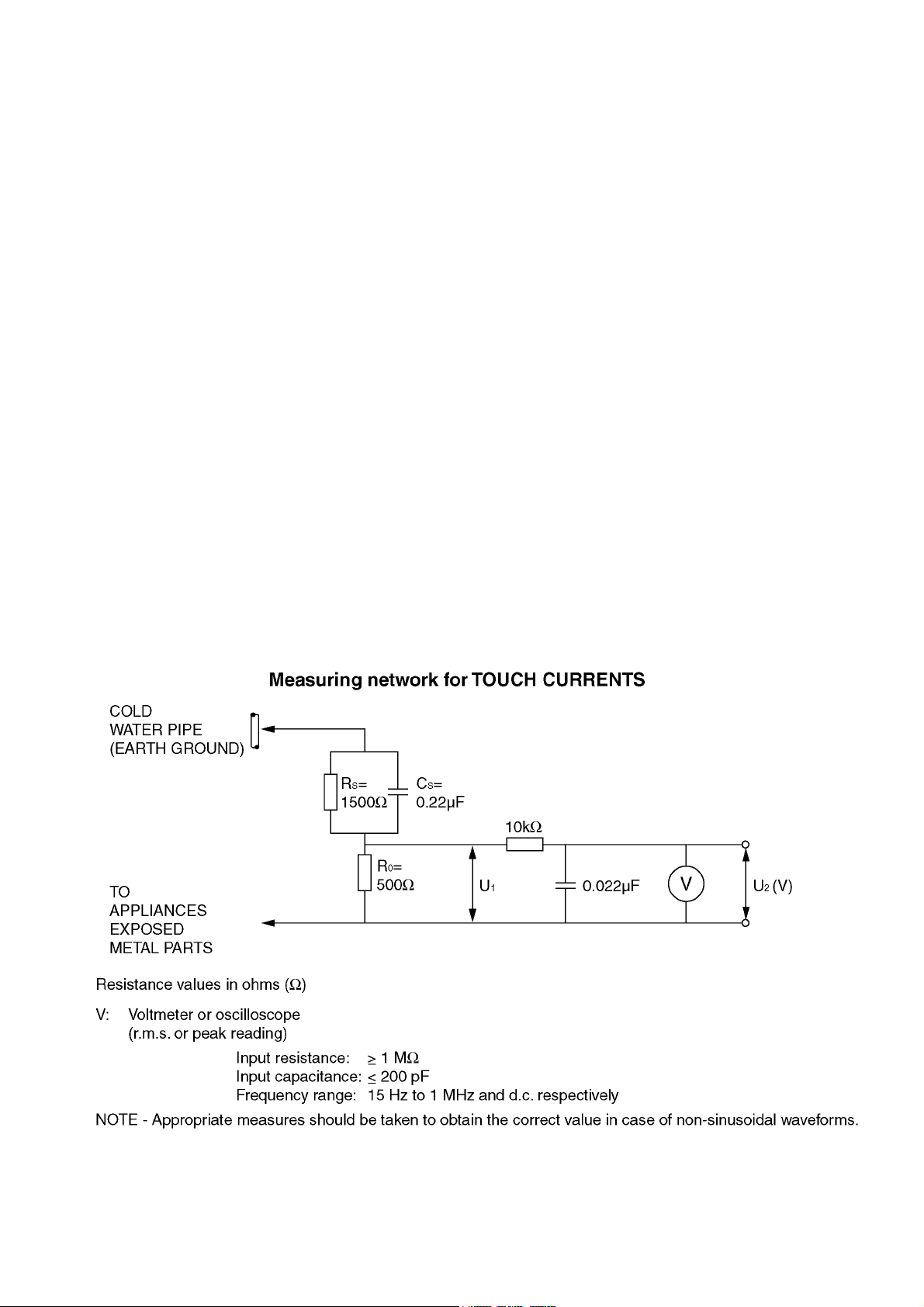
1.2. Touch-Current Check
1. Plug the AC cord directly into the AC outlet. Do not use an isolation transformer for this check.
2. Connect a measuring network for touch currents between each exposed metallic part on the set and a good earth ground
such as a water pipe, as shown in Figure 1.
3. Use Leakage Current Tester (Simpson 228 or equivalent) to measure the potential across the measuring network.
4. Check each exposed metallic part, and measure the voltage at each point.
5. Reserve the AC plug in the AC outlet and repeat each of the above measure.
6. The potential at any point (TOUCH CURRENT) expressed as voltage U
For a. c.: U1 = 35 V (peak) and U2 = 0.35 V (peak);
For d. c.: U
Note:
The limit value of U
mA d. c.
The limit value U
7. In case a measurement is out of the limits specified, there is a possibility of a shock hazard, and the equipment should be
repaired and rechecked before it is returned to the customer.
= 1.0 V,
1
= 0.35 V (peak) for a. c. and U1 = 1.0 V for d. c. correspond to the values 0.7 mA (peak) a. c. and 2.0
2
= 35 V (peak) for a. c. correspond to the value 70 mA (peak) a. c. for frequencies greater than 100 kHz.
1
and U2, does not exceed the following values:
1
Figure 1
3

TH-65VX300ER
2Warning
2.1. Prevention of Electrostatic Discharge (ESD) to Electrostatically Sensitive (ES) Devices
Some semiconductor (solid state) devices can be damaged easily by static electricity. Such components commonly are called Electrostatically Sensitive (ES) Devices. Examples of typical ES devices are integrated circuits and some field-effect transistors and
semiconductor “chip” components. The following techniques should be used to help reduce the incidence of component damage
caused by electrostatic discharge (ESD).
1. Immediately before handling any semiconductor component or semiconductor-equipped assembly, drain off any ESD on your
body by touching a known earth ground. Alternatively, obtain and wear a commercially available discharging ESD wrist strap,
which should be removed for potential shock reasons prior to applying power to the unit under test.
2. After removing an electrical assembly equipped with ES devices, place the assembly on a conductive surface such as aluminum foil, to prevent electrostatic charge buildup or exposure of the assembly.
3. Use only a grounded-tip soldering iron to solder or unsolder ES devices.
4. Use only an anti-static solder removal device. Some solder removal devices not classified as “anti-static (ESD protected)” can
generate electrical charge sufficient to damage ES devices.
5. Do not use freon-propelled chemicals. These can generate electrical charges sufficient to damage ES devices.
6. Do not remove a replacement ES device from its protective package until immediately before you are ready to install it. (Most
replacement ES devices are packaged with leads electrically shorted together by conductive foam, aluminum foil or comparable conductive material).
7. Immediately before removing the protective material from the leads of a replacement ES device, touch the protective material
to the chassis or circuit assembly into which the device will be installed.
Caution
Be sure no power is applied to the chassis or circuit, and observe all other safety precautions.
8. Minimize bodily motions when handling unpackaged replacement ES devices. (Otherwise ham less motion such as the brushing together of your clothes fabric or the lifting of your foot from a carpeted floor can generate static electricity (ESD) sufficient
to damage an ES device).
4
TH-65VX300ER
2.2. About lead free solder (PbF)
Note: Lead is listed as (Pb) in the periodic table of elements.
In the information below, Pb will refer to Lead solder, and PbF will refer to Lead Free Solder.
The Lead Free Solder used in our manufacturing process and discussed below is (Sn+Ag+Cu).
That is Tin (Sn), Silver (Ag) and Copper (Cu) although other types are available.
This model uses Pb Free solder in it’s manufacture due to environmental conservation issues. For service and repair work, we’d
suggest the use of Pb free solder as well, although Pb solder may be used.
PCBs manufactured using lead free solder will have the PbF within a leaf Symbol PbF stamped on the back of PCB.
Caution
• Pb free solder has a higher melting point than standard solder. Typically the melting point is 50 ~ 70 °F (30~40 °C) higher. Please
use a high temperature soldering iron and set it to 700 ± 20 °F (370 ± 10 °C).
• Pb free solder will tend to splash when heated too high (about 1100 °F or 600 °C).
If you must use Pb solder, please completely remove all of the Pb free solder on the pins or solder area before applying Pb solder. If this is not practical, be sure to heat the Pb free solder until it melts, before applying Pb solder.
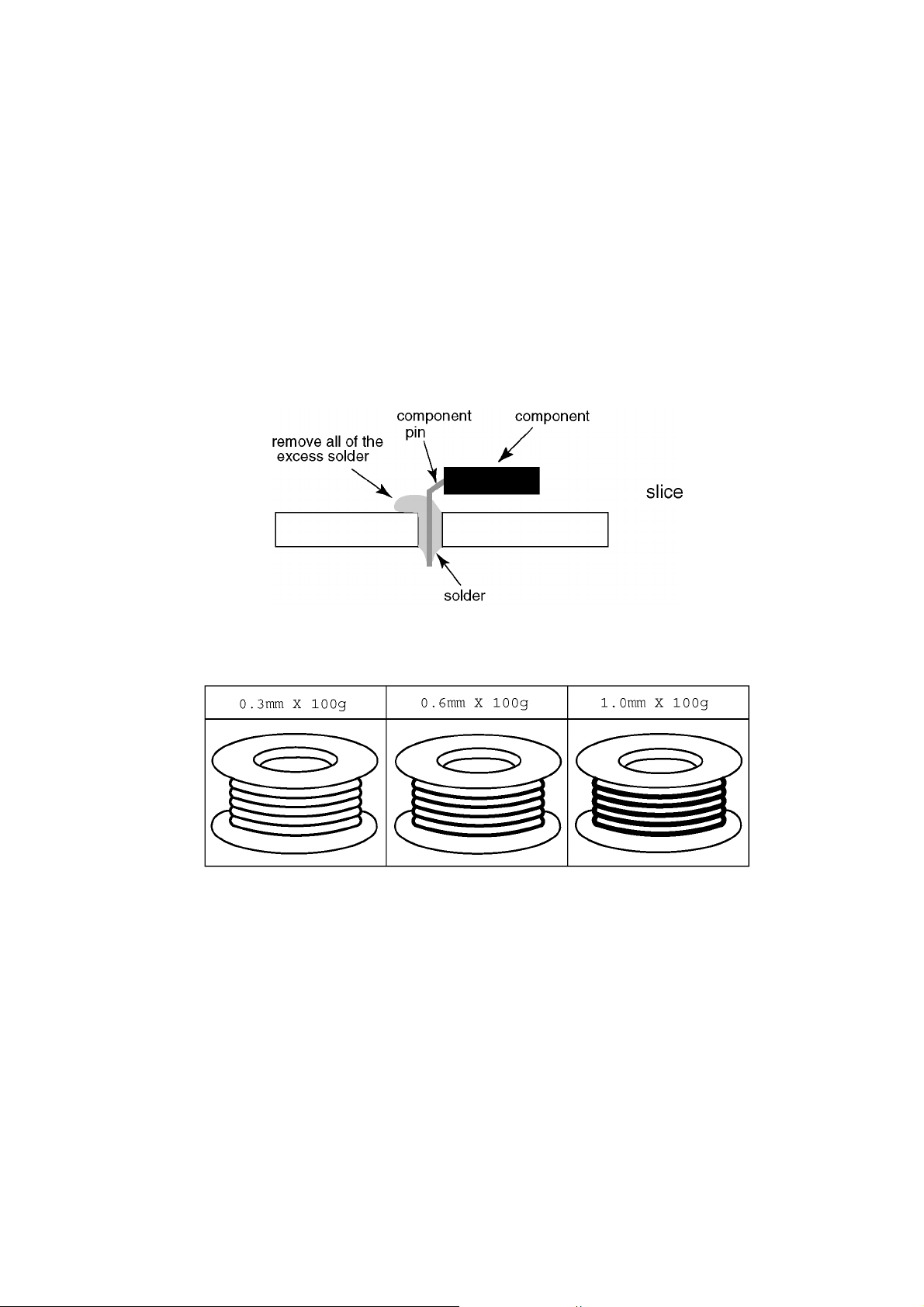
• After applying PbF solder to double layered boards, please check the component side for excess solder which may flow onto the
opposite side. (see figure below)
Suggested Pb free solder
There are several kinds of Pb free solder available for purchase. This product uses Sn+Ag+Cu (tin, silver, copper) solder. However, Sn+Cu (tin, copper), Sn+Zn+Bi (tin, zinc, bismuth) solder can also be used.
5
TH-65VX300ER
3 Service Navigation
3.1. Service Hint
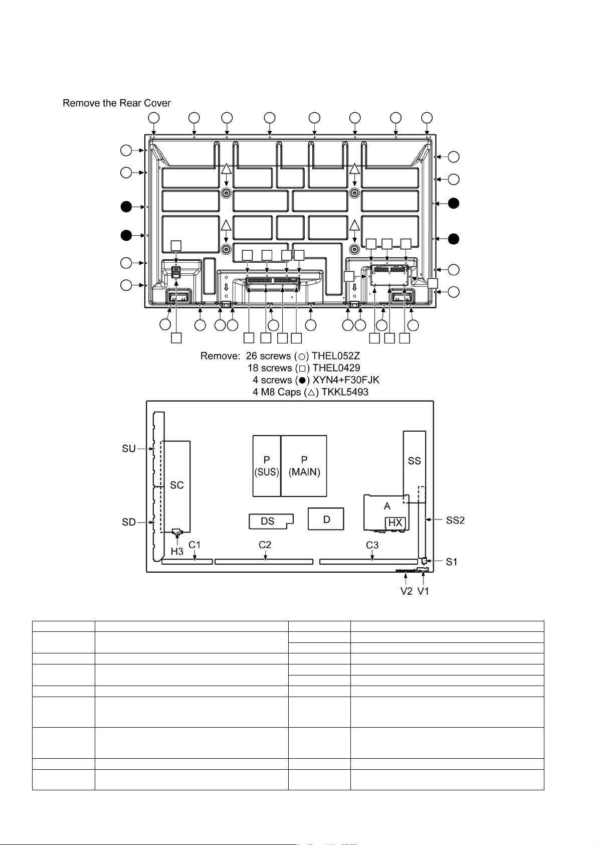
Board Name Function Board Name Function
A Digital Signal Processor, Microcomputer
Audio Processor, Speaker Out Amplifier
DS Slot Interface C3 Data drive (Left)
D Format Converter, Plasma AI Processor
Sub-Field Processor, Sync Processor
SC Scan drive V2 Key switch
SU Scan out (Upper)
Non serviceable.
SU-Board should be exchanged for service.
SD Scan out (Lower)
Non serviceable.
SD-Board should be exchanged for service.
SS Sustain drive H3 Speaker terminal
SS2 Sustain out HX PC / RS-232C_Input terminal, 3D Signal out, Speaker
C1 Data drive (Right)
C2 Data drive (Centre)
S1 Power switch
V1 Remote receiver, LED-G, R
P (MAIN) Power supply
P (SUS) Power supply
terminal (L)
6
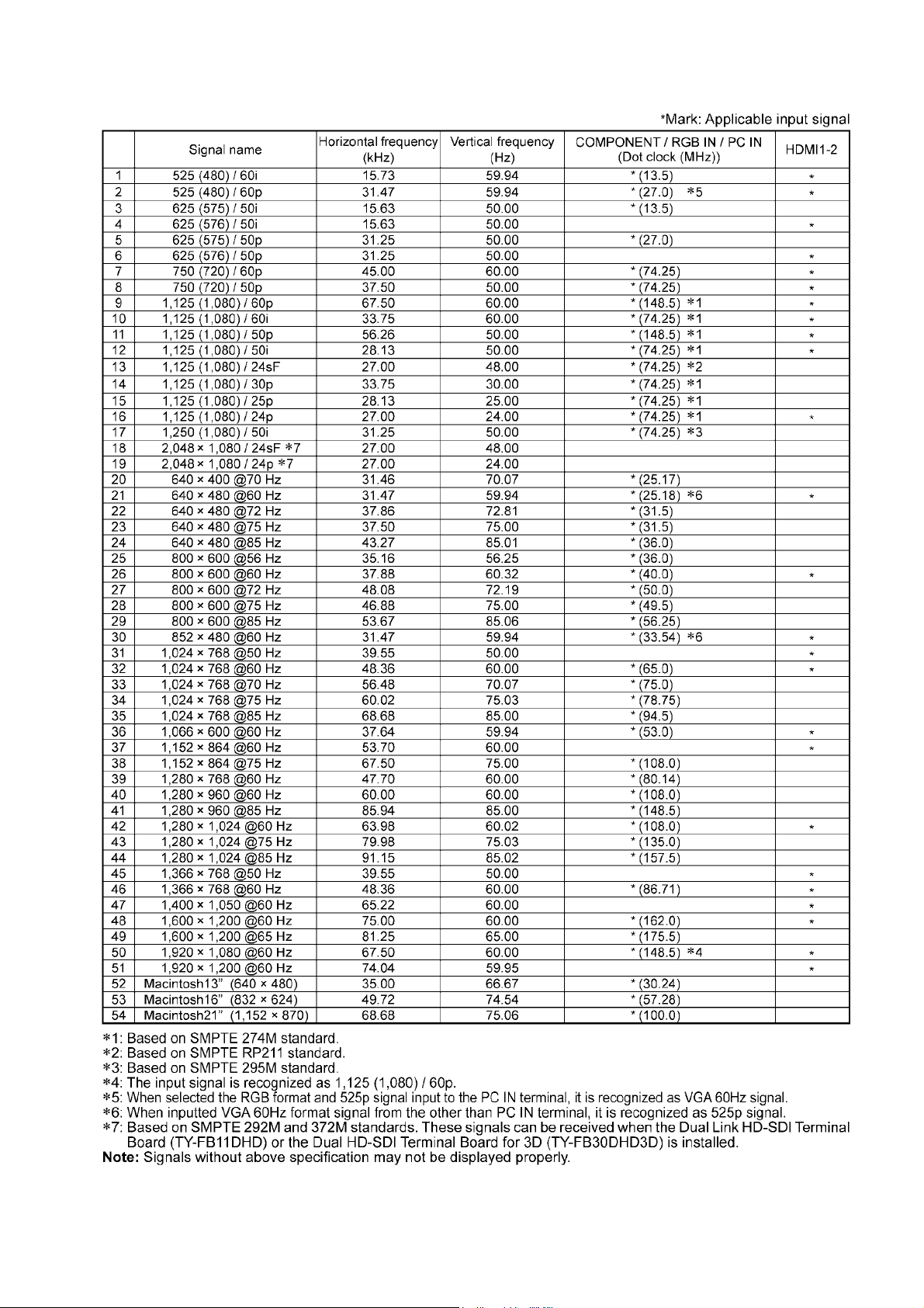
3.2. Applicable signals
TH-65VX300ER
7

TH-65VX300ER
4 Specifications
Product Fiche
Energy efficiency class D
Visible screen size (diagonal) 165 cm / 65 inches
On mode average power consumption
Annual energy consumption 569 kWh/year
Standby power consumption 0.50 W
Off mode power consumption 0.30 W
Display resolution 1,920 (W) × 1,080 (H)
Power Source 220 - 240 V AC, 50/60 Hz
Rated power consumption 450 W
Standby power consumption Save off 0.8 W, Save on 0.5 W
Plasma Display panel Drive method : AC type
Screen size 1,434 mm (W) × 806 mm (H) × 1,645 mm (diagonal)
(No.of pixels) 2,073,600 (1,920 (W) × 1,080 (H)) [5,760 × 1,080 dots]
Operating condition
Temperature 0 °C - 40 °C
Humidity 20 % - 80 %
Applicable signals
Scanning format
PC signals VGA, SVGA, XGA, SXGA
Connection terminals
LAN
AV IN HDMI 1-2 TYPE A Connector × 2
COMPONENT / RGB IN
Y / G RCA Pin jack with sync 1.0 Vp-p (75-ohm)
P
B/CB
P
R/CR
AUDIO L-R RCA Pin jack × 2 0.5 Vrms
PC IN High-Density Mini D-sub 15 Pin Y or G with sync 1.0 Vp-p (75-ohm)
AUDIO Stereo mini jack (M3) × 1 0.5 Vrms
SERIAL External Control Terminal
3D IR TRANSMITTER for 3D IR TRANSMITTER
EXT SP 8-ohm, 20 W [10 W + 10 W] (10 % THD)
Accessories Supplied
Remote Control Transmitter N2QAYB000688
Batteries R6 (UM3) Size × 2
Clamper TMME289 × 1
Ferrite core J0KG00000014 × 2
Dimensions (W × H × D) 1,554 mm × 924 mm × 94 mm
Mass (weight)
main unit only approx. 60.0 kg net
with speakers approx. 66.0 kg
Notes:
• Design and specifications are subject to change without notice. Mass and dimensions shown are approximate.
• This equipment complies with the EMC standards listed below.
EN55022, EN55024, EN61000-3-2, EN61000-3-3.
• Product fiche: Based on (EU) No.1062/2010 ANNEX III
• ENERGY LABEL attached on the back cover is only for European countries.
390 W
Energy consumption XYZ kWh per year, based on the power consumption of the television operating
4 hours per day for 365 days. The actual energy consumption will depend on how the television is used.
65-inch, 16:9 aspect ratio
525 (480) / 60i 60p, 625 (575) / 50i 50p, 750 (720) / 60p 50p, 1125 (1080) /
60i 60p 50i 50p 24p 25p 30p 24sF, 1250 (1080) / 50i
UXGA ..... (compressed)
Horizontal scanning frequency 15 - 110 kHz
Vertical scanning frequency 48 - 120 Hz
RJ45 10BASE-T/100BASE-TX, compatible with PJLink
/B RCA Pin jack 0.7 Vp-p (75-ohm)
/R RCA Pin jack 0.7 Vp-p (75-ohm)
VBS (use HD port) with picture 1.0 Vp-p (high impedance)
D-sub 9 Pin RS-232C compatible
3D SHUTTER OUT M3 jack × 1
DC 8V OUT Centre plus, for EIAJ 4mm plug
TM
Y or G without sync 0.7 Vp-p (75-ohm)
/ CB / B:0.7 Vp-p (75-ohm)
P
B
P
/ CR / R:0.7 Vp-p (75-ohm)
R
HD / VD:1.0 - 5.0 Vp-p (high impedance)
without picture 0.3 Vp-p (high impedance)
8
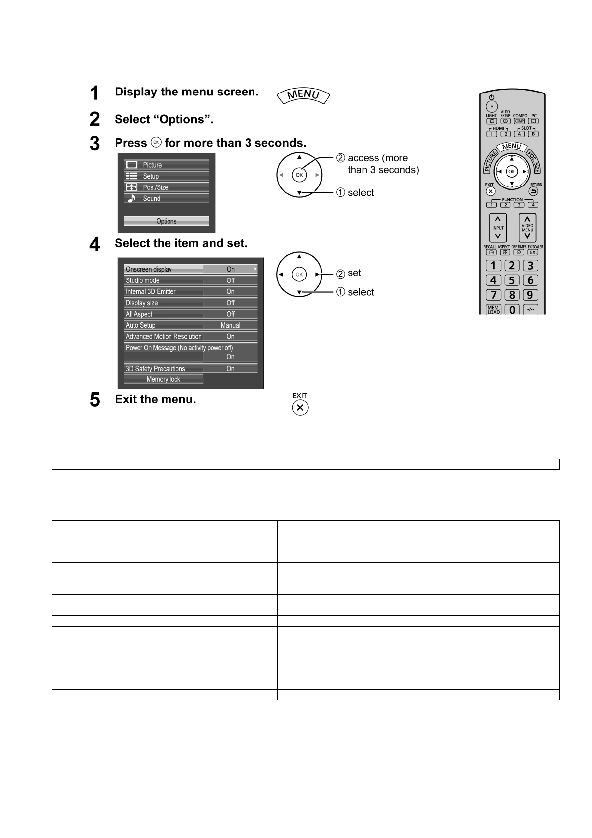
5 Operating Instructions
TH-65VX300ER
Option Menu for GPF14DMONV series
GPF14DMONV chassis series have special function and operation setting facility called Option Menu. This Option Menu is
useful for special function required customers. This should be set at the installation stage.
Option menus default setting Contents
Onscreen display On Enable/Disable to display input mode indication after power on and no signal
Studio mode On For switching functions in setting menus used for television studio applications.
Internal 3D Emitter On Set the infrared transmitter for the 3D Eyewear.
Display size Off Display size function On/Off
All Aspect Off Aspect mode: default/All aspect mode.
Auto Setup Manual Sets the operational mode of the automatic position adjustment in the POS./
Advanced Motion Resolution On Displays motion picture images at higher resolution.
Power On Message (No activity power
off)
3D Safety Precautions On 3D Safety Precautions show/hide is set during power ON.
Memory lock --- Locks or unlocks saved profiles. Also for setting passwords.
On Whether to show/hide No activity power off Precautions at the time of power ON
indication.
SIZE menu.
is set.
When the setting changes from
played as below.
Pressing
“YES” switches the setting.
“On” to “Off”, the confirmation screen is dis-
9

TH-65VX300ER
6 Service Mode
6.1. CAT (Computer Aided Test) mode
How to access the CAT mode.
Method A : Main unit + remote control operation
Press and hold the button on the front panel of the unit and press the RECALL button on the remote control
3 times quickly within 2 second, this will place the unit into the CAT mode.
To exit the CAT mode, access the ID mode and switch off the main power.
Method B : Remote control operation only
1. Set the OFF timer with the [OFF TIMER] button except for 0 minute.
(30 minutes, 60minutes, 90 minutes)
2. Set the volume level of sound to 0.
(Referred to the volume level setting method)
3. Press the RECALL button more than 3 seconds.
How to Exit
Switch off the main power.
Volume level setting method
In order to set a volume level of sound as 0, please set up with the Sound menu.
1. Pushed the MENU button and select [Sound].
2. Select [Volume], and Choose the [0] with the left button.
10
TH-65VX300ER
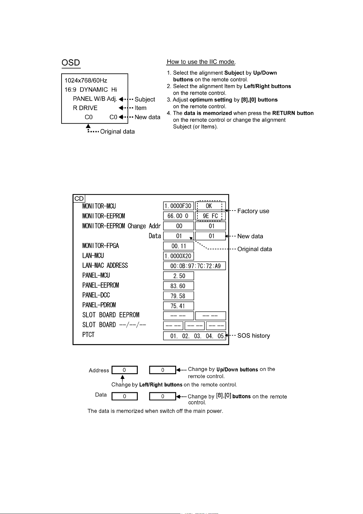
6.1.1. IIC mode
Select the IIC mode by Up/Down button on the remote control at the front page of CAT mode and then press the OK button on the
remote control.
Subject and item are mentioned on “IIC mode structure”.
To exit the IIC mode, press the RETURN button on the remote control.
6.1.2. CD mode
Select the CD mode by Up/Down button on the remote control at the front page of CAT mode and then press the [5] button on the
remote control more than 3 seconds.
Memory data change
To exit the CD mode, press the RETURN button on the remote control.
11
TH-65VX300ER
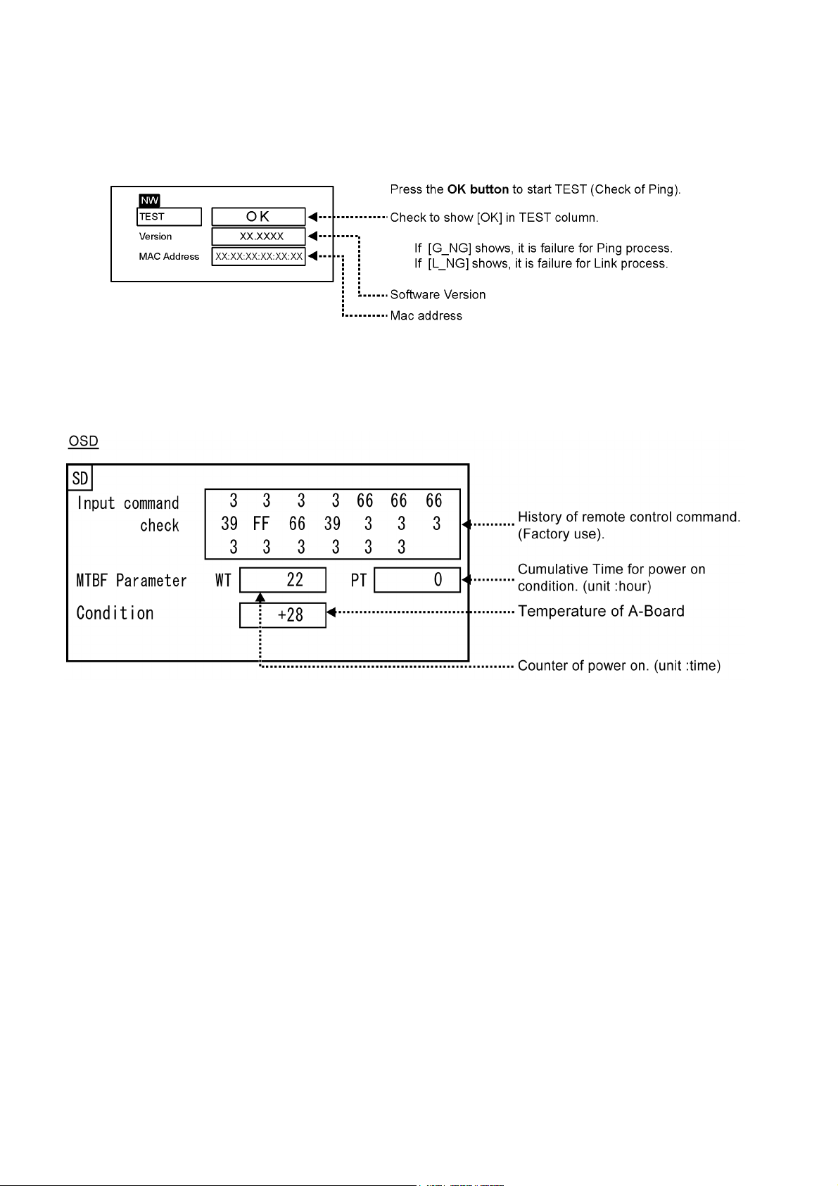
6.1.3. NW mode
Note :
To display NW mode, set CONTROL I/F SELECT in NETWORK SETUP to [LAN].
Select the NW mode by Up/Down button on the remote control at the front page of CAT mode and then press the OK button on
the remote control.
To exit the NW mode, press the RETURN button on the remote control.
6.1.4. SD mode
Select the SD mode by Up/Down button on the remote control at the front page of CAT mode and then press the OK button on the
remote control.
To exit the SD mode, press the RETURN button on the remote control.
12

TH-65VX300ER
6.1.5. MS mode
Select the MS mode by Up/Down button on the remote control at the front page of CAT mode and then press the [5] button on the
remote control more than 3 seconds.
To exit the MS mode, press the RETURN button on the remote control.
Caution:
Market Select should be set after exchange of A-Board.
Destination number
Number Model (Destination)
1 65VX300U (North America)
3 65VX300W (Asia, Oceania, ME)
20 65VX300ER (Europe, CIS)
Default setting
Number Destination
1North America
6.1.6. ID mode
Select the ID mode by Up/Down button on the remote control at the front page of CAT mode and then press the [5] button on the
remote control more than 3 seconds.
To exit the ID mode, press the RETURN button on the remote control.
13
TH-65VX300ER
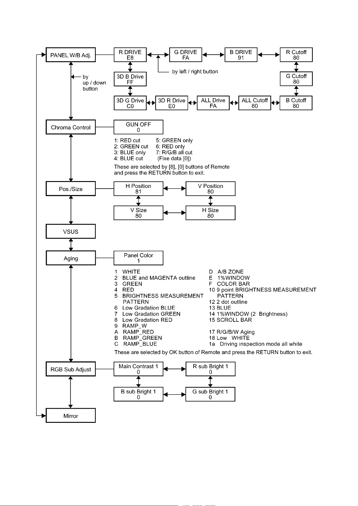
6.2. IIC mode structure (following items value is sample data)
14

7 Troubleshooting Guide
7.1. Self Check
7.1.1. Display Indication
1. Self-check is used to automatically check the bus line
controlled circuit of the Plasma display.
2. To get into the Self-check mode, press the volume down
button on the customer controls at the bottom of the set,
at the same time pressing the OFF-TIMER button on the
remote control, and the screen will show.
If the IIC ports have been checked and found to be incorrect
Or not located then “ - - ” will appear in place of “ OK ”
“ 01 ” in the line of the “ PTCT ” means the number of blinks of
the Power LED is 1. (Reference to 7.1.2)
“ H09 ” in the line of the “ PTCT ” is the error code.
To exit the CAT mode switch off the main power.
Note:
The line of the “ PTCT ” displays when you get into the Selfcheck mode for the first time only after the Power LED
blinks.
TH-65VX300ER
15
TH-65VX300ER
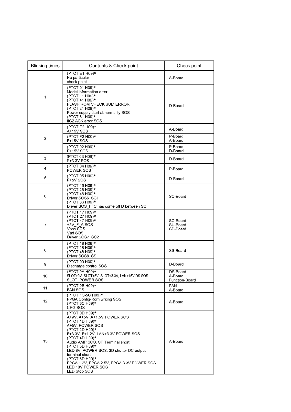
7.1.2. Power LED Blinking timing chart
1. Subject
Information of LED Blinking timing chart.
2. Contents
When an abnormality has occurred to the unit, the protection circuit operates and resets to the stand by mode. At this time,
the defective block can be identified by the number of blinks of the Power LED on the front panel of the unit.
* Refer to 7.1.1 Display Indication
16

7.2. No Power
First check point
There are following 3 states of No Power indication by power LED.
1. No lit.
2. Green is lit then turns red blinking a few seconds later.
3. Only red is lit.
TH-65VX300ER
7.3. No Picture
17
TH-65VX300ER
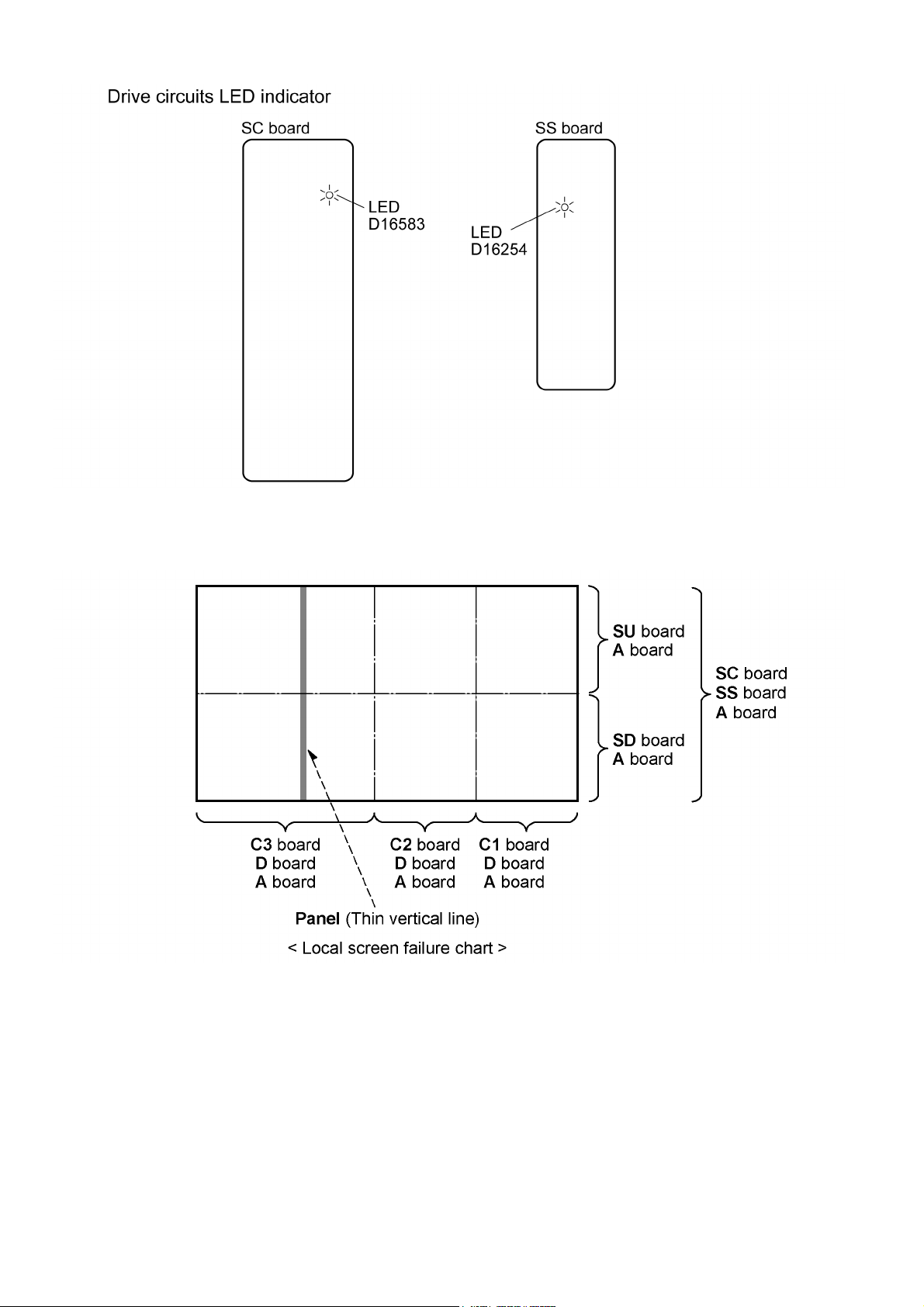
7.4. Local screen failure
Plasma display may have local area failure on the screen. Fig - 1 is the possible defect P.C.B. for each local area.
Fig - 1
18
TH-65VX300ER
8 Service Fixture & Tools
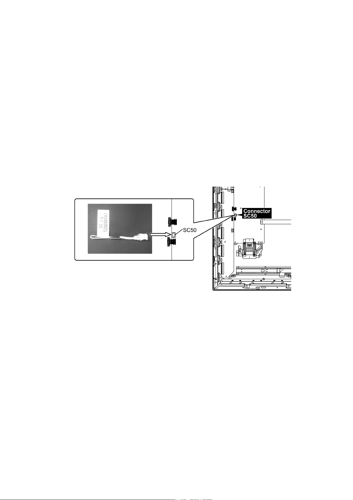
8.1. SC jig
Purpose:
To find the failure board (SC or SU/SD) when the power LED is blinking 7 times.
SC jig:
Jumper connector to connect to SC50 connector on SC board
Part number:
TZSC09187
How to use:
Caution: Remove SC jig from SC board after inspection.
1. Remove all connector between SC board and SU/SD board to isolate SC board from both SU and SD board electrically.
Note: The board will be damaged if all connector is not removed (for example; remove connector only for SU board
and stay connecting with SD board. The board will be damaged.)
2. Connect SC jig to connector SC50 at left bottom side of SC board.
3. Turn on the TV/Display Unit and confirm the power LED blinking.
LED blinking: Possible cause of failure is in SC board
No LED blinking (Lighting or no lighting): Possible cause of failure is in SU or SD board
4. After inspection, turn off the TV/Display Unit and wait a few minutes to discharge.
5. Remove SC jig from SC board.
19
TH-65VX300ER
9 Disassembly and Assem-
bly Instructions
• To disassemble P.C.B., wait for 1 minute after power was off
for discharge from electrolysis capacitors.
• , , , , , and marks indicate screw positions.
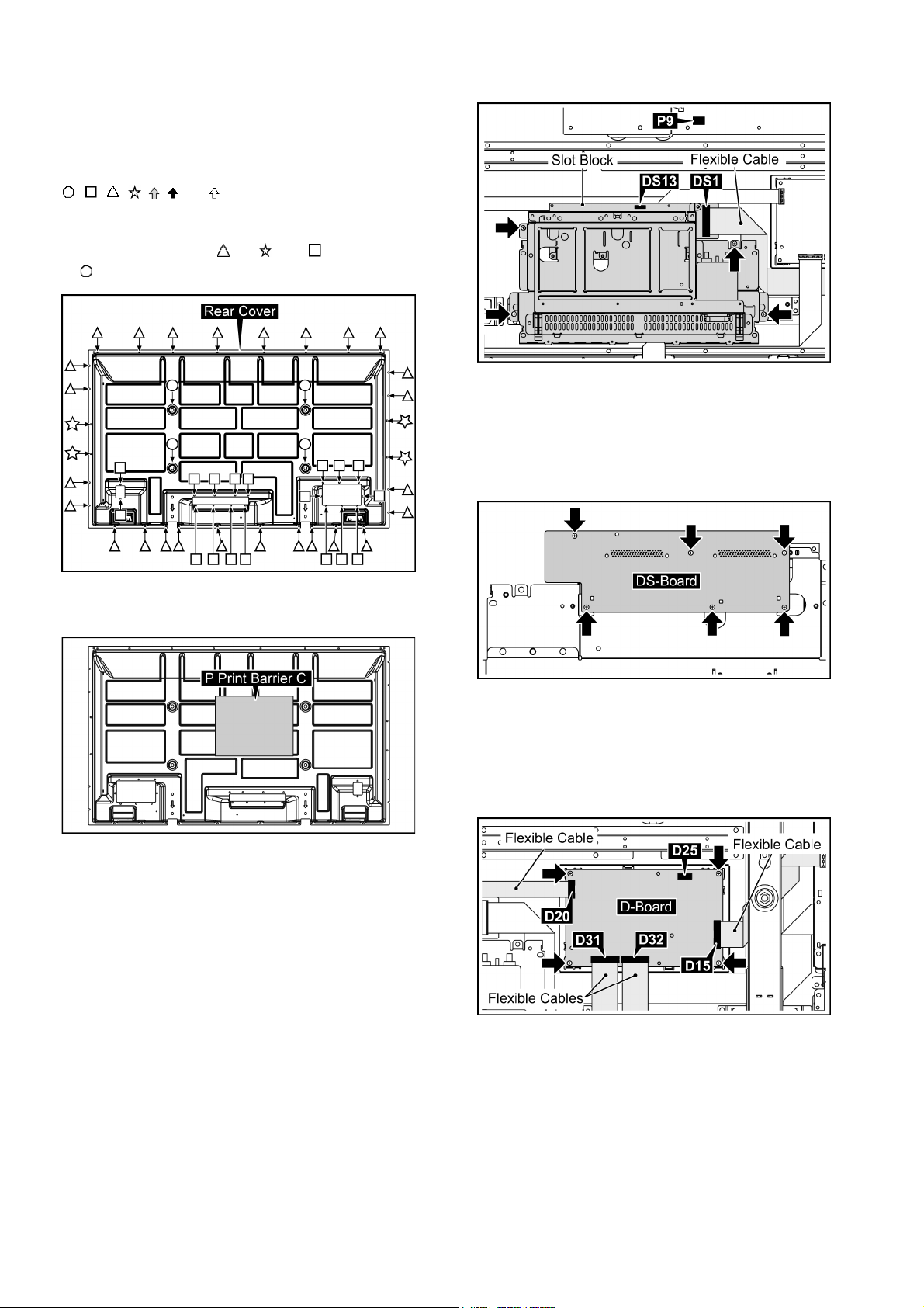
9.1. Removal of Rear Cover
1. Remove screws (×26 , ×4 , ×18 ) and M8 Cap (×4
) and then remove the Rear Cover.
3. Remove 4 screws and then remove the Slot Block.
9.3. Removal of DS-Board
1. Remove the Slot Block.
(Refer to Removal of Slot Block)
2. Turn over the Slot Block.
3. Remove 6 screws and then remove DS-Board.
2. Turn over the Rear Cover.
3. Remove the P Print Barrier (C).
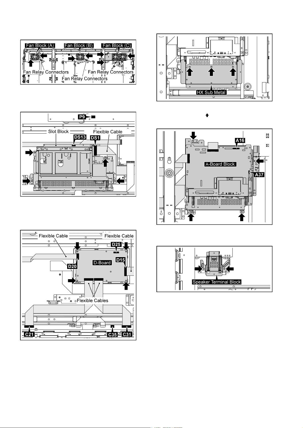
9.2. Removal of Slot Block
1. Disconnect the connectors (DS13, P9).
2. Remove the flexible cable from the connector (DS1).
9.4. Removal of D-Board
1. Disconnect the connector (D25).
2. Remove the flexibles cable from the connectors (D15,
D20, D31, D32).
3. Remove 4 screws and then remove D-Board.
9.5. Removal of HX-Board
1. Disconnect the connectors (A14, A38).
20

TH-65VX300ER
2. Remove 2 Hexagonal-Head screws, 4 screws ( ), 1
screws ( ) and 2 screw ( ) and then remove the HXBoard Block.
3. Turn over the HX-Board Block.
4. Disconnect the connectors (HX1, HX2).
5. Remove 2 Hexagonal-Head screws and 1 screw of HXBoard and then remove HX-Board.
4. Remove 4 screws and then remove A-Board.
Note: when fixing A-Board
• Put the flexible Cable between the Fixed Metal and ABoard when Connect the flexible Cable to the connector
(A1).
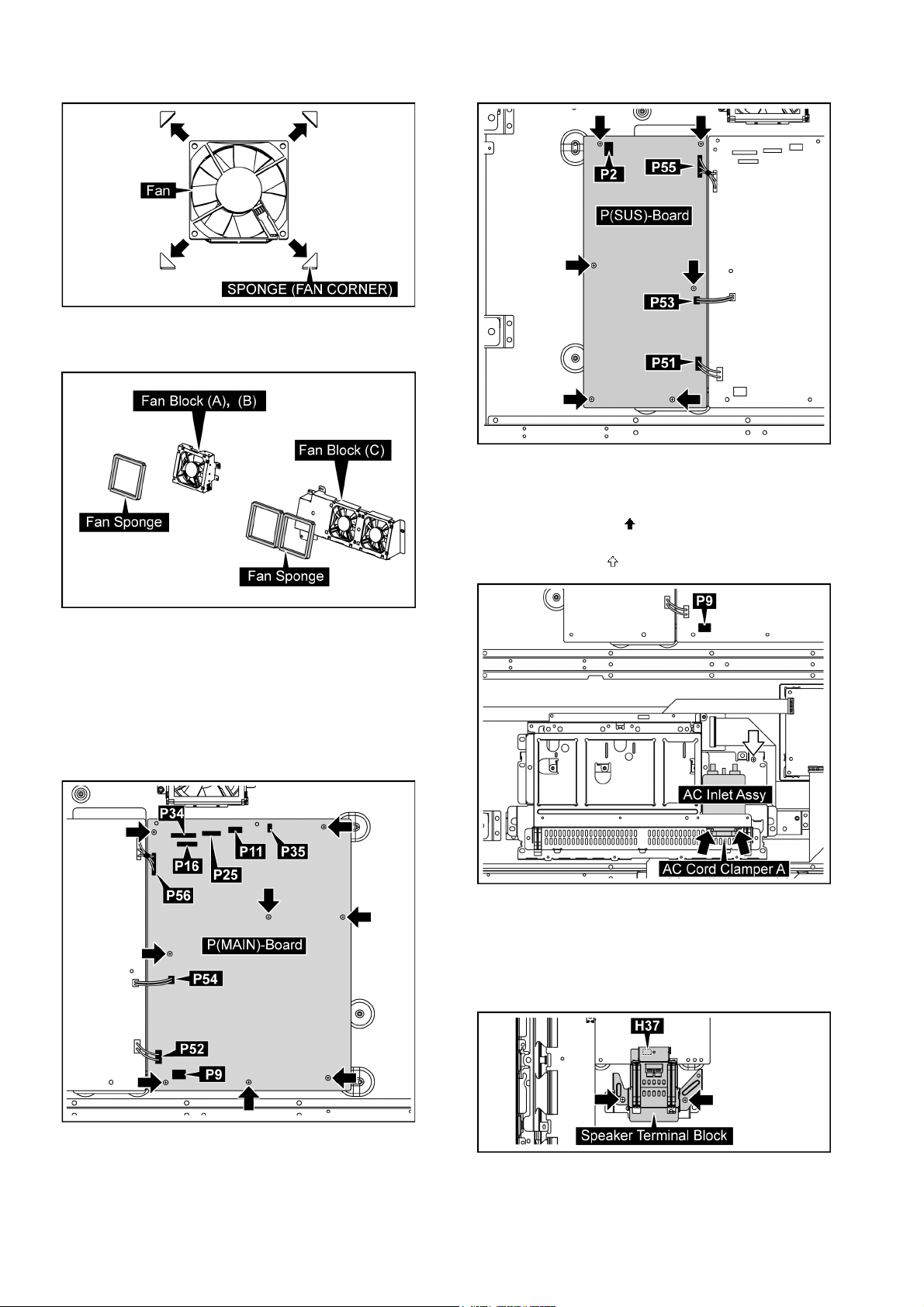
9.7. Removal of Fan
1. Disconnect the Fan Relay Connectors.
2. Remove 7 screws and then remove the Fan Block (A),
(B), (C) and the Duct Barrier (A).
9.6. Removal of A-Board
1. Remove the HX-Board Block.
(Refer to Removal of HX-Board)
2. Disconnect the connectors (A5, A11, A13, A16, A22, A33,
A37).
3. Remove the flexible cables from the connectors (A1,
A15).
3. Remove each 1 screw and then remove the Fan from the
Fan Fixed Metal.
21
TH-65VX300ER
4. Remove each 4 SPONGE(FAN CORNER) from the Fan.
5. Reassemble the Fans in reverse order.
6. Stick the Fan Sponges around the Fan.
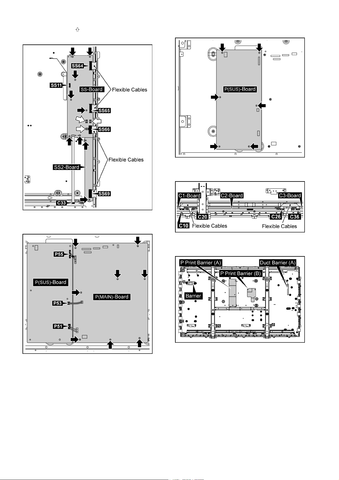
2. Remove 6 screws and then remove P(SUS)-Board.
9.10. Removal of AC Inlet Assy
1. Disconnect the connector (P9).
2. Remove 2 screws ( ) and then remove the AC Cord
Clamper A.
3. Remove 1 screw ( ) and then remove the AC Inlet Assy.
Note:
The Fan Sponge is not re-usable.
Please use a new one when Fan exchange.
9.8. Removal of P(MAIN)-Board
1. Disconnect the connectors (P9, P11, P16, P25, P34, P35,
P52, P54, P56).
2. Remove 8 screws and then remove P(MAIN)-Board.
9.11. Removal of H3-Board
1. Disconnect the connector (H37).
2. Remove 2 screw and then remove the Speaker Terminal
Block.
9.9. Removal of P(SUS)-Board
1. Disconnect the connectors (P2, P51, P53, P55).
22
TH-65VX300ER
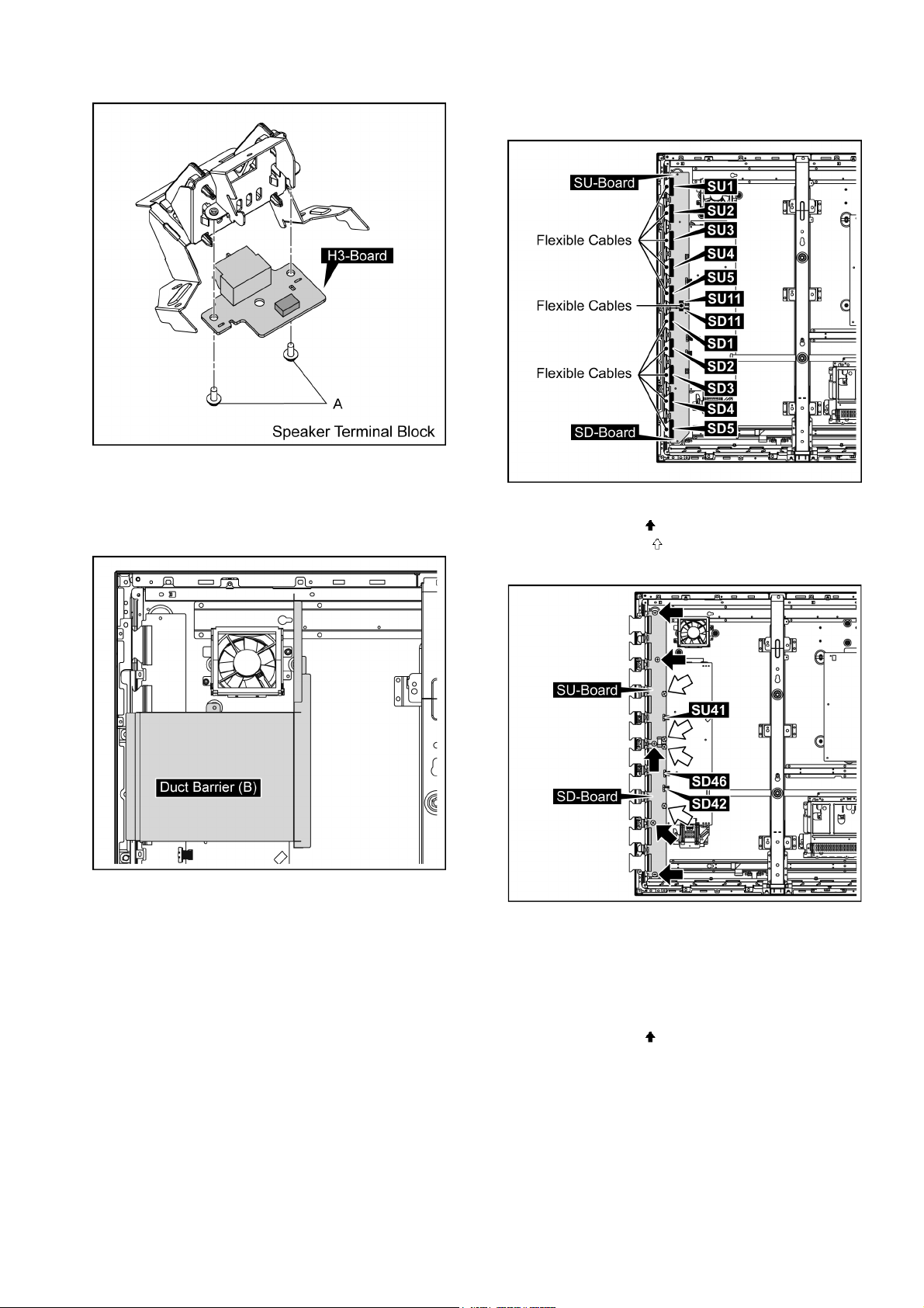
3. Remove 2 screws (A) and then remove H3-Board.
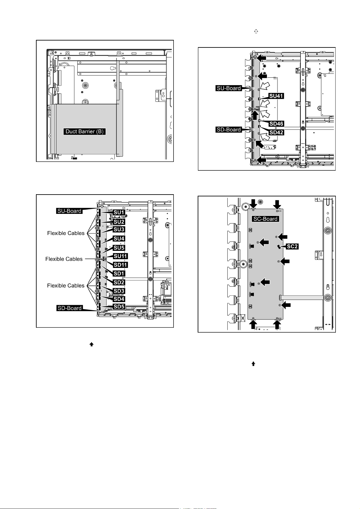
9.12. Removal of SU-Board and SDBoard
1. Remove the Duct Barrier (B).
2. Remove the flexible cables from the connectors (SU1,
SU2, SU3, SU4, SU5, SU11, SD1, SD2, SD3, SD4, SD5,
SD11).
3. Disconnect the connectors (SU41, SD42, SD46).
4. Remove 5 screws ( ).
5. Remove 4 screws ( ) and then remove SU-Board and
SD-Board.
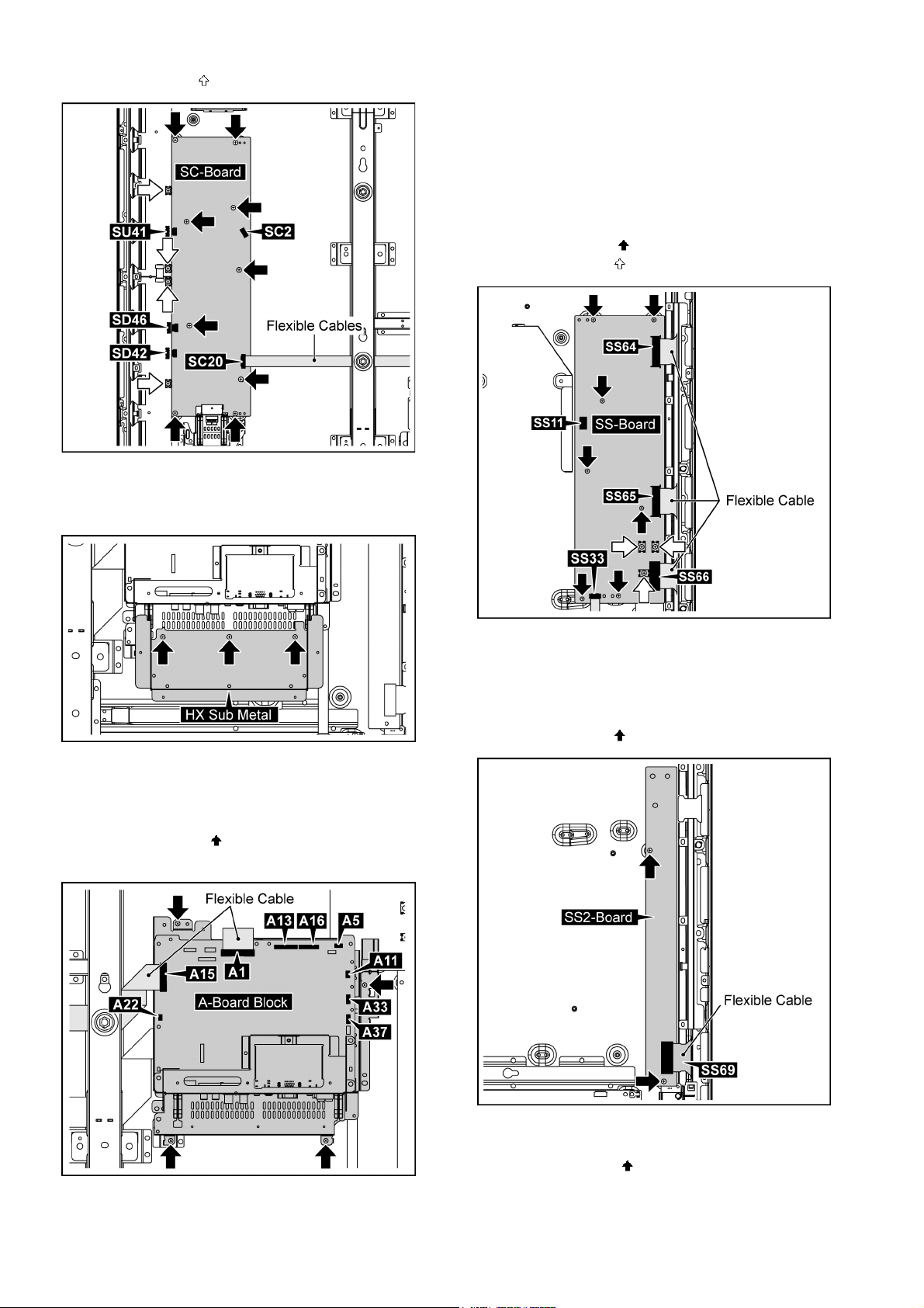
9.13. Removal of SC-Board
1. Remove the Fan-Duct Barrier (B).
(Refer to Removal of SU-Board and SD-Board)
2. Disconnect the connectors (SC2, SD42, SD46, SU41).
3. Remove the flexible cable from the connector (SC20).
4. Remove 9 screws ( ).
23
TH-65VX300ER
5. Remove 4 screws ( ) and then remove SC-Board.
9.14. Removal of SS-Board
1. Remove 3 screws and then remove the HX Sub Metal.
Note: when fixing A-Board Block
• Put the flexible Cable between the Fixed Metal and ABoard when Connect the flexible Cable to the connector
(A1).
5. Remove the Fan Block (C).
(Refer to remove of Fan Block).
6. Disconnect the connector (SS11).
7. Remove the flexible cables from the connectors (SS33,
SS64, SS65, SS66).
8. Remove 7 screws ( ).
9. Remove 3 screws ( ) and then remove SS-Board.
2. Disconnect the connectors (A5, A11, A13, A16, A22, A33,
A37).
3. Remove the flexible cables from the connectors (A1,
A15).
4. Remove 4 screws ( ) and then remove the A-Board
Block.
9.15. Removal of SS2-Board
1. Remove the SS-Board.
(Refer to remove of SS-Board).
2. Remove the flexible cable from the connector (SS69).
3. Remove 2 screws ( ) and then remove SS2-Board.
9.16. Removal of C1-Board
1. Remove 15 screws ( ).
24
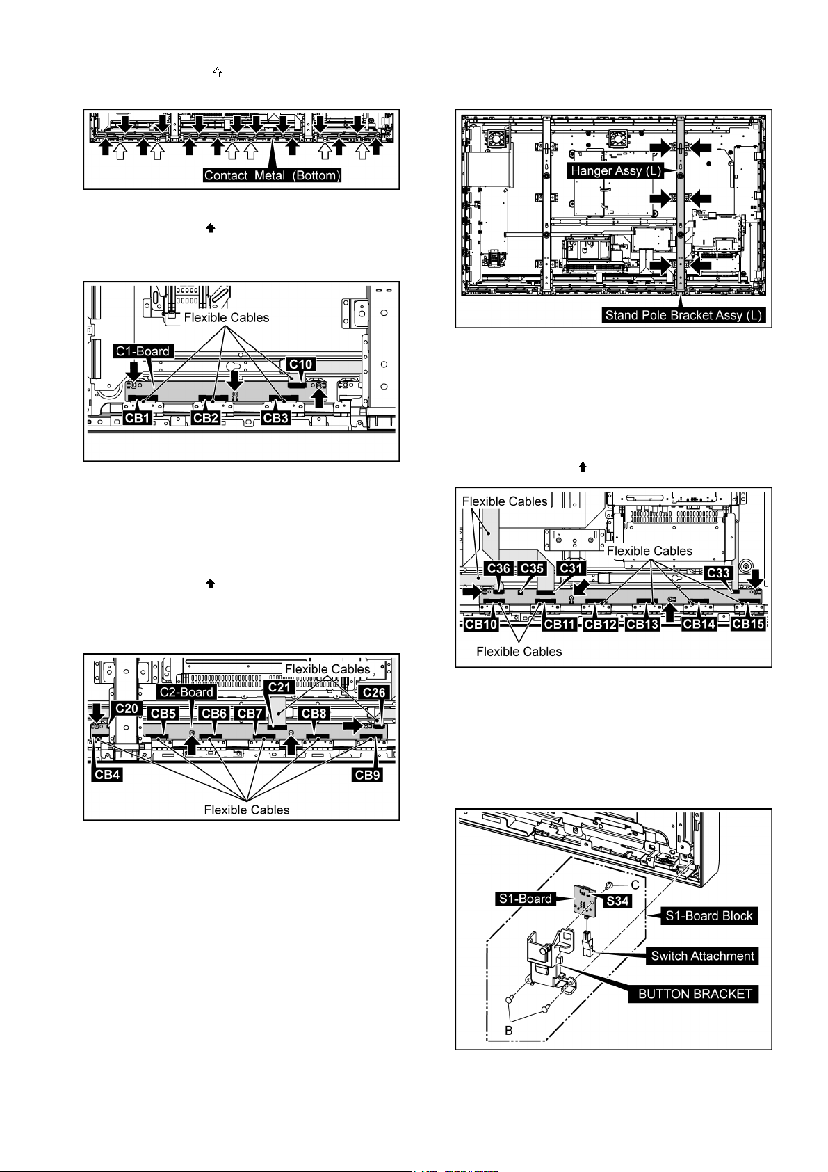
TH-65VX300ER
2. Remove 6 screws ( ) and then remove Contact Metal
(bottom).
3. Remove the flexible cable from the connector (C10).
4. Remove 3 screws ( ).
5. Remove the flexible cables from the connectors (CB1,
CB2, CB3) and then remove C1-Board.
2. Remove 6 screws and then remove the Hanger Assy (L)
and the Stand Pole Bracket Assy (L).
1. Remove the Contact Metal (Bottom).
(Refer to remove of C1-Board).
2. Disconnect the connector (C35).
3. Remove the flexible cables from the connectors (C31,
C33, C36).
4. Remove the flexible cables from the connectors (CB10,
CB11, CB12, CB13, CB14, CB15).
5. Remove 4 screws ( ) and then remove C3-Board.
9.17. Removal of C2-Board
1. Remove the Contact Metal (bottom).
(Refer to remove of C1-Board).
2. Remove the flexible cables from the connectors (C20,
C21, C26).
3. Remove 4 screws ( ).
4. Remove remove the flexible cables from the connectors
(CB4, CB5, CB6, CB7, CB8, CB9) and then remove C2Board.
9.18. Removal of C3-Board
1. Remove the Fan Block (C).
(Refer to remove of Fan).
9.19. Removal of S1-Board
1. Remove 2 screws (B) and then remove the S1-Board
Block.
2. Disconnect the connector (S34).
3. Remove 1 screw (C) and then remove S1-Board.
4. Remove the Switch Attachment from S1-Board.
25
TH-65VX300ER
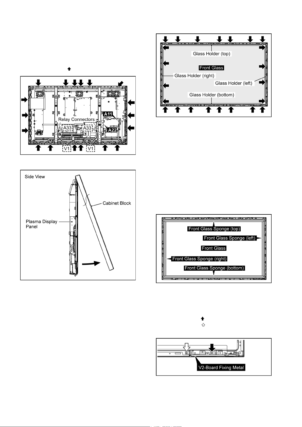
9.20. Removal of Front Glass, V, V1, V2-Board and Cabinet Assy
1. Remove the S1-Board Block.
(Refer to Removal of S1-Board)
2. Disconnect the connectors (A11, A22).
3. Disconnect the Relay connectors (A33-V1).
4. Remove 18 screws ( ).
5. Pull the bottom of the Cabinet Block forward and lift.
2. Remove the Front Glass.
Note: when fixing Glass Holder (upper-rear, bottomrear)
• When the glass holder is tightened in the screw, it does
so that the positioned front glass should not move.
• There must not be floatage in glass holder and the
screw.
• After insertion, glass holder tighten the screw in the rib in
the medial aspect in the cabinet.
9.20.1. Removal of Front Glass
1. Remove 23 screws and then remove the Fixed Angle
(left, right, upper-rear, bottom-rear).
Note: when Front Glass is exchanged
• Stick all Sponges on the Front-Glass.
• Attach them without uplift and peeling.
• As sticking them, avoid causing any space between the
Sponge and the joint part in each corner for a prevention
of dirt and dust.
Note
• The sponges are parts which cannot be recycled. Please
use the new article when you exchange the Front Glass.
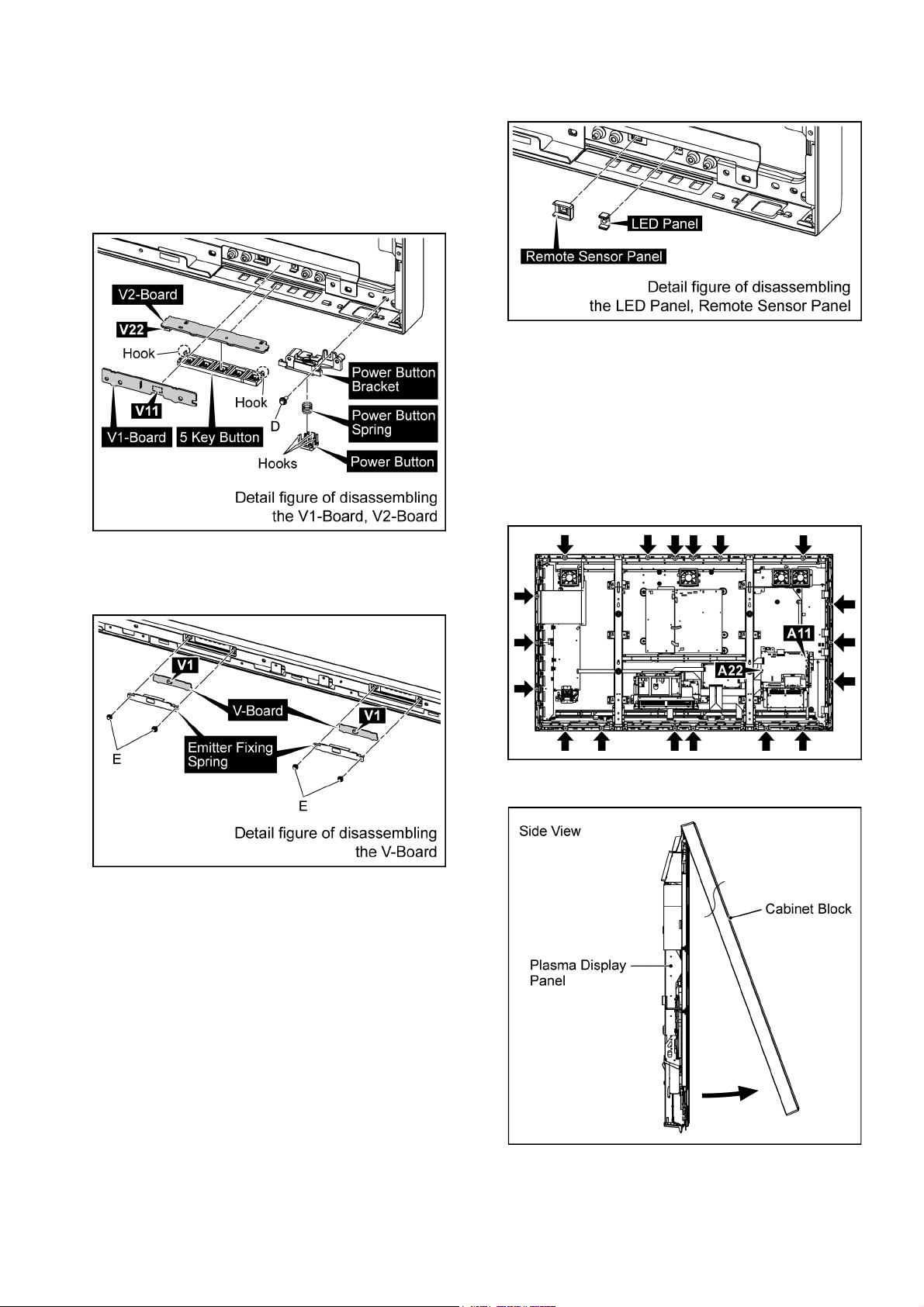
9.20.2. Removal of V1-Board and V2-Board
1. Remove 1 screws ( ).
2. Remove 1 screws ( ) and then remove V2-Board Fixing
Metal.
3. Remove 1 screw (D).
26
TH-65VX300ER
4. Remove 3 Hooks and then remove the Power Button and
Power Button Spring.
5. Disconnect the connector (V11) and then remove V1Board.
6. Disconnect the connector (V22) and then remove V2Board.
7. Remove 2 hooks and then remove the 5 Key Button from
V2-Board.
3. Remove the LED Panel and Remote Sensor Panel and
then remove the Cabinet Assy.
9.21. Removal of Plasma Display Panel
The C1,C2,C3 Boards are connected with the plasma display panel for the repair.
1. Remove the S1-Board Block.
(Refer to Removal of S1-Board)
2. Disconnect the connectors (A11, A22).
3. Remove 18 screws.
8. Remove each 2 screws (E) and then remove the V-Board
from the Emitter Fixing Spring.
9. Disconnect the connectors (v1).
9.20.3. Removal of Cabinet Assy
1. Remove the Front Glass.
(Refer to Removal of Front Glass)
2. Remove V1-Board and V2-Board.
(Refer to Removal of V1-Board and V2-Board)
4. Pull the bottom of the Cabinet Block forward and lift.
5. Disconnect the Fan Relay Connectors.
27
TH-65VX300ER
6. Remove 7 screws and then remove the Fan Block (A),
(B) and the Fan Block (C).
7. Disconnect the connectors (DS13, P9).
8. Remove the flexible cable from the connector (DS1).
9. Remove 4 screws and then remove the Slot Block.
13. Remove 3 screws and then remove the HX Sub Metal.
14. Disconnect the connectors (A16, A37).
15. Remove 4 screws ( ) and then remove the A-Board
Block.
10. Disconnect the connectors (D25, C35).
11. Remove the flexible cable from the connectors (C21,
C31, D15, D20).
12. Remove 4 screws and then remove the D-Board.
16. Remove 2 screw and then remove the Speaker Terminal
Block.
28
TH-65VX300ER
17. Remove the Fan-Duct Barrier (B).
18. Remove the flexible cables from the connectors (SU1,
SU2, SU3, SU4, SU5, SU11, SD1, SD2, SD3, SD4, SD5,
SD11).
21. Remove 4 screws ( ) and then remove SU-Board and
SD-Board.
22. Disconnect the connector (SC2).
23. Remove 9 screws and then remove SC-Board.
19. Disconnect the connectors (SD42, SD46, SU41).
20. Remove 5 screws ( ).
24. Disconnect the connector (SS11).
25. Remove the flexible cables from the connectors (C33,
SS64, SS65, SS66, SS69).
26. Remove 9 screws ( ).
29
TH-65VX300ER
27. Remove 3 screws ( ) and then remove SS-Board and
SS2-Board.
30. Remove 6 screws and then remove P(SUS)-Board.
31. Remove the flexible cables from the connectors (C10,
C20, C26, C36).
28. Disconnect the connectors (P51, P53, P55).
29. Remove 8 screws and then remove P(MAIN)-Board.
32. Remove the P Print Barrier (A, B), Duct Barrier (A) and
Barrier.
30
 Loading...