

Page 1

Operating Instructions
65-inch model
65-inch model
55-inch model
55-inch model
49-inch model
49-inch model
43-inch model
43-inch model
EU
Functional Manual
FULL HD LCD Display For business use
Model No. TH-65SF2U
TH-55SF2U
TH-49SF2U
TH-43SF2U
This manual is common to all the models regardless of suffixes of the
*
model number.
U : for US, Canada and Mexico
E : for EU and CIS
TH-65SF2E
TH-55SF2E
TH-49SF2E
TH-43SF2E
English
Please read these instructions before operating your set
and retain them for future reference.
DPQP1157ZC
Page 2

Dear Panasonic Customer
Welcome to the Panasonic family of customers. We hope that
you will have many years of enjoyment from your new LCD
Display.
To obtain maximum benefit from your set, please read these
Instructions before making any adjustments, and retain them
for future reference.
Retain your purchase receipt also, and note down the model
number and serial number of your set in the space provided
on the rear cover of these instructions.
Visit our Panasonic Web Site http://panasonic.com
Table of Contents
Before use
●
Illustrations and screens in this Operating Instructions
are images for illustration purposes, and may be
different from the actual ones.
●
Descriptive illustrations in this Operating Instructions
are created mainly based on the 65-inch model.
Important Safety Instructions ..........................4
FCC STATEMENT .............................................. 5
Important Safety Notice ................................... 6
Safety Precautions ........................................... 8
Precautions for use ........................................ 11
Accessories ....................................................13
Accessories Supply ·········································· 13
Remote Control Batteries ·································· 14
Kensington security ....................................... 14
Connections .................................................... 15
AC cord connection and fixing / Cable fixing ·········· 15
Video equipment connection ······························ 17
Before connecting ············································ 18
HDMI 1 and HDMI 2 terminals connection ············· 18
DVI-D IN / DVI-D OUT terminal connection ··········· 19
PC IN terminal connection ································· 21
AV IN terminal connection ··································22
DIGITAL LINK terminal connection ······················ 22
* DIGITAL LINK is for TH-65SF2E only.
SERIAL IN / SERIAL OUT terminal connection ·······23
IR IN/IR OUT terminal connection ······················· 25
AUDIO OUT terminal connection ························· 26
USB terminal connection ··································· 26
Identifying Controls ........................................28
Main unit ························································ 28
Remote Control Transmitter ······························· 29
Basic Controls ................................................ 30
Selecting the input signal ··································· 31
RECALL·························································32
Volume Adjustment ··········································32
Sound mute On / Off ········································· 33
OFF TIMER ···················································· 33
ASPECT Controls ........................................... 34
Digital ZOOM ................................................... 35
English
2
Page 3

On-Screen Menu Displays ............................. 36
Adjusting Position .......................................... 38
Auto setup ······················································ 38
Sound Adjustment .......................................... 40
Picture Adjustments ....................................... 41
Picture Profiles ............................................... 44
Saving profiles ················································ 45
Loading profiles ··············································· 45
Editing profiles ················································ 46
Setup menu ..................................................... 47
Signal ···························································· 47
Screensaver (For preventing image retention)········ 50
Input label ······················································ 51
Power management settings ······························ 51
HDMI-CEC settings ·········································· 53
Image settings ················································· 54
Wobbling ························································ 55
No activity power off ········································· 55
OSD language ················································ 55
Multi display settings ········································ 56
Set up timer ···················································· 57
Date and time ················································· 57
Network settings ·············································· 59
USB media player settings ································· 62
Memory viewer settings ····································· 63
Function button settings ···································· 64
Display orientation ··········································· 66
Image rotation ················································· 66
OSD position ·················································· 66
Menu display duration ······································· 66
Menu transparency ·········································· 66
Options Adjustments .....................................67
Using Network Function ................................ 77
Necessary environment for computers to be connected
Example of network connection ·························· 77
Command control ············································ 79
Control Command via LAN ································ 79
PJLink protocol ················································ 83
Multi Monitoring & Control Software ····················· 84
Video Wall Manager ·········································84
Content Management Software ··························· 84
··· 77
Connecting with LAN ..................................... 85
Computer operation ·········································· 85
Using Web Browser Control .......................... 85
Before Using Web Browser Control ····················· 85
Access from Web Browser ································· 86
Operating with Web Browser ······························ 86
Using Web Browser Control ······························· 93
USB media player ........................................... 95
Function description ········································· 95
Preparation ····················································· 96
Playing back the files ········································ 98
Network environment (Multi Media Player only) ···· 100
Starting / ending Media Player ·························· 101
Resume Play function ····································· 101
Playlist edit function· ······································· 102
Schedule playback function using “Content
Management Software” ··································· 103
Memory viewer..............................................107
Preparation ··················································· 107
Displaying the “Memory viewer” screen ·············· 109
Playing the pictures ·········································110
Playing the video / music ··································111
About HDMI-CEC function ........................... 112
Connection ····················································112
Setting ··························································112
Interlocking devices ·········································112
Operating a device (using the remote control of this
unit) ·····························································113
Data Cloning ................................................. 114
Copying data to other display via LAN ·················114
Copying the display data to the USB memory ·······116
Copying the USB memory data to the display ·······117
USB memory network settings ................... 118
Saving the LAN setting file to the USB memory device ····
Copying the USB memory data to the display ·······118
118
ID Remote Control Function ........................ 119
Setting the remote control’s ID number ················119
Cancelling the setting of remote control’s ID number
(ID “0”) ··························································119
Entering characters ...................................... 120
Preset Signals ............................................... 121
Shipping condition ....................................... 123
Troubleshooting ...........................................124
Specifications ............................................... 128
Software License .......................................... 131
English
3
Page 4

WARNING
65-inch model
Important Safety Instructions
WARNING: To reduce the risk of electric shock,
do not remove cover or back.
No user-serviceable parts inside. Refer servicing
to qualified service personnel.
The lightning flash with arrow-head within a
triangle is intended to tell the user that parts
inside the product are a risk of electric shock
to persons.
The exclamation point within a triangle
is intended to tell the user that important
operating and servicing instructions are in the
papers with the appliance.
WARNING :
To prevent damage which may result in fire or
shock hazard, do not expose this apparatus to
rain or moisture.
Do not place containers with water (flower vase,
cups, cosmetics, etc.) above the set.
(including on shelves above, etc.)
WARNING :
1) To prevent electric shock, do not remove cover. No
user serviceable parts inside. Refer servicing to
qualified service personnel.
2) Do not remove the grounding pin on the power
plug. This apparatus is equipped with a three pin
grounding-type power plug. This plug will only fit
a grounding-type power outlet. This is a safety
feature. If you are unable to insert the plug into the
outlet, contact an electrician.
Do not defeat the purpose of the grounding plug.
(
only)
1) Read these instructions.
2) Keep these instructions.
3) Heed all warnings.
4) Follow all instructions.
5) Do not use this apparatus near water.
6) Clean only with dry cloth.
7) Do not block any ventilation openings. Install in
accordance with the manufacturer’s instructions.
8) Do not install near any heat sources such as
radiators, heat registers, stoves, or other apparatus
(including amplifiers) that produce heat.
9) Do not defeat the safety purpose of the polarized or
grounding-type plug. A polarized plug has two blades
with one wider than the other. A grounding type plug
has two blades and a third grounding prong. The
wide blade or the third prong are provided for your
safety. If the provided plug does not fit into your
outlet, consult an electrician for replacement of the
obsolete outlet. (
10) Protect the power cord from being walked on
or pinched particularly at plugs, convenience
receptacles, and the point where they exit from the
apparatus.
11) Only use attachments / accessories specified by the
manufacturer.
12) Use only with the cart, stand, tripod,
bracket, or table specified by the
manufacturer, or sold with the apparatus.
When a cart is used, use caution when
moving the cart / apparatus combination
to avoid injury from tip-over.
13) Unplug this apparatus during lightning storms or
when unused for long periods of time.
14) Refer all servicing to qualified service personnel.
Servicing is required when the apparatus has been
damaged in any way, such as power-supply cord or
plug is damaged, liquid has been spilled or objects
have fallen into the apparatus, the apparatus has
been exposed to rain or moisture, does not operate
normally, or has been dropped.
15) To prevent electric shock, ensure the grounding pin
on the AC cord power plug is securely connected.
(
65-inch model
65-inch model
only)
only)
English
4
Page 5

FCC STATEMENT
This equipment has been tested and found to comply
with the limits for a class A digital device, pursuant to
Part 15 of the FCC Rules. These limits are designed
to provide reasonable protection against harmful
interference when the equipment is operated in a
commercial environment. This equipment generates,
uses and can radiate radio frequency energy and, if not
installed and used in accordance with the instructions
manual, may cause harmful interference to radio
communications. Operation of this equipment in a
residential area is likely to cause harmful interference
in which case the user will be required to correct the
interference at his own expense.
FCC CAUTION:
To assure continued compliance, follow the attached
installation instructions and use only the provided
power supply cord. Any changes or modifications
not expressly approved by Panasonic Corp. of North
America could void the user’s authority to operate
this device.
Supplier’s Declaration of Conformity
Model No.
TH-65SF2U, TH-55SF2U, TH-49SF2U,TH-43SF2U
Responsible Party:
Panasonic Corporation of North America
Two Riverfront Plaza, Newark, New Jersey
07102-5490
Contact Source:
Panasonic System Solutions Company of North
America
1-877-655-2357
General Contact:
http://shop.panasonic.com/support
This device complies with Part 15 of the FCC Rules and
all applicable IC RSS standards. Operation is subject
to the following two conditions: (1) This device may not
cause harmful interference, and (2) this device must
accept any interference received, including interference
that may cause undesired operation.
CANADIAN NOTICE:
This Class A digital apparatus complies with
Canadian ICES-003.
WARNING:
Not for use in a computer room as defined in the
•
Standard for the Protection of Electronic Computer/
Data Processing Equipment, ANSI/NFPA 75.
For permanently connected equipment, a readily
•
accessible disconnect device shall be incorporated
in the building installation wiring.
For pluggable equipment, the socket-outlet shall
•
be installed near the equipment and shall be easily
accessible.
Note:
Image retention may occur. If you display a still
picture for an extended period, the image might
remain on the screen. However, it will disappear when
a general moving picture is displayed for a while.
Trademark Credits
Microsoft, Windows and Internet Explorer are the
•
registered trademarks or trademarks of Microsoft
Corporation in the United States and/or other
countries.
Mac, macOS and Safari are the trademarks of
•
Apple Inc. registered in the United States and other
countries.
PJLink is a registered or pending trademark in Japan,
•
the United States, and other countries and regions.
HDMI, High-Definition Multimedia Interface and the
•
HDMI Logo are trademarks or registered trademarks
of HDMI Licensing Administrator, Inc. in the United
States and other countries.
JavaScript is a registered trademark or a trademark of
•
Oracle Corporation and its subsidiary and associated
companies in the United States and/or other
countries.
RoomView, Crestron RoomView and Fusion RV are
•
registered trademarks of Crestron Electronics, Inc.
Crestron Connected is the trademark of Crestron
Electronics, Inc.
Even if no special notation has been made of company
or product trademarks, these trademarks have been fully
respected.
English
5
Page 6

Important Safety
65-inch model
Notice
WARNING
1) To prevent damage which may result in fire or
shock hazard, do not expose this appliance to
dripping or splashing.
Do not place containers with water (flower vase,
cups, cosmetics, etc.) above the set. (including on
shelves above, etc.)
No naked flame sources, such as lighted candles,
should be placed on / above the set.
2) To prevent electric shock, do not remove cover. No
user serviceable parts inside. Refer servicing to
qualified service personnel.
3) Do not remove the earthing pin on the power
plug. This apparatus is equipped with a three pin
earthing-type power plug. This plug will only fit an
earthing-type power outlet. This is a safety feature.
If you are unable to insert the plug into the outlet,
contact an electrician.
Do not defeat the purpose of the earthing plug.
(
65-inch model
4) To prevent electric shock, ensure the earthing pin
on the AC cord power plug is securely connected.
(
CAUTION
This appliance is intended for use in environments
which are relatively free of electromagnetic fields.
Using this appliance near sources of strong
electromagnetic fields or where electrical noise may
overlap with the input signals could cause the picture
and sound to wobble or cause interference such as
noise to appear.
To avoid the possibility of harm to this appliance, keep
it away from sources of strong electromagnetic fields.
only)
only)
IMPORTANT INFORMATION
If a display is not positioned in a sufficiently stable
location, it can be potentially hazardous due to falling.
Many injuries, particularly to children, can be avoided
by taking simple precautions such as:
Using cabinets or stands recommended by the
•
manufacturer of the display.
Only using furniture that can safely support the
•
display.
Ensuring the display is not overhanging the edge
•
of the supporting furniture.
Not placing the display on tall furniture (for
•
example, cupboards or bookcases) without
anchoring both the furniture and the display to a
suitable support.
Not standing the displays on cloth or other
•
materials placed between the display and
supporting furniture.
Educating children about the dangers of climbing
•
on furniture to reach the display or its controls.
WARNING:
This equipment is compliant with Class A of CISPR32.
In a residential environment this equipment may
cause radio interference.
English
6
Page 7

65-inch model
IMPORTANT: THE MOULDED PLUG
55-inch model
43-inch model
FOR YOUR SAFETY, PLEASE READ THE
FOLLOWING TEXT CAREFULLY.
This display is supplied with a moulded three pin
mains plug for your safety and convenience. A 10
amp fuse is fitted in this plug. Shall the fuse need to
be replaced, please ensure that the replacement fuse
has a rating of 10 amps and that it is approved by
ASTA or BSI to BS1362.
Check for the ASTA mark
the body of the fuse.
If the plug contains a removable fuse cover, you must
ensure that it is refitted when the fuse is replaced.
If you lose the fuse cover the plug must not be used
until a replacement cover is obtained.
A replacement fuse cover can be purchased from
your local Panasonic dealer.
Do not cut off the mains plug.
Do not use any other type of mains lead except the
one supplied with this display.
The supplied mains lead and moulded plug are
designed to be used with this display to avoid
interference and for your safety.
If the socket outlet in your home is not suitable, get it
changed by a qualified electrician.
If the plug or mains lead becomes damaged,
purchase a replacement from an authorized dealer.
WARNING : — THIS DISPLAY MUST BE EARTHED
How to replace the fuse.
Open the fuse compartment with a screwdriver and
replace the fuse.
or the BSI mark on
49-inch model
IMPORTANT: THE MOULDED PLUG
FOR YOUR SAFETY, PLEASE READ THE
FOLLOWING TEXT CAREFULLY.
This display is supplied with a moulded three pin
mains plug for your safety and convenience. A 5 amp
fuse is fitted in this plug. Shall the fuse need to be
replaced, please ensure that the replacement fuse
has a rating of 5 amps and that it is approved by
ASTA or BSI to BS1362.
Check for the ASTA mark
the body of the fuse.
If the plug contains a removable fuse cover, you must
ensure that it is refitted when the fuse is replaced.
If you lose the fuse cover the plug must not be used
until a replacement cover is obtained.
A replacement fuse cover can be purchased from
your local Panasonic dealer.
Do not cut off the mains plug.
Do not use any other type of mains lead except the
one supplied with this display.
The supplied mains lead and moulded plug are
designed to be used with this display to avoid
interference and for your safety.
If the socket outlet in your home is not suitable, get it
changed by a qualified electrician.
If the plug or mains lead becomes damaged,
purchase a replacement from an authorized dealer.
How to replace the fuse.
Open the fuse compartment with a screwdriver and
replace the fuse.
or the BSI mark on
English
7
Page 8

Safety Precautions
65-inch model
55-inch model
49-inch model
43-inch model
WARNING
■ Setup
This LCD Display is for use only with the following
optional accessories.
Use with any other type of optional accessories may
cause instability which could result in the possibility
of injury.
Securely install the pedestal, an optional accessory. Ask
an authorized dealer for installation.
Pedestal
•
65-inch model 55-inch model
TY-ST55PE9
49-inch model 43-inch model
TY-ST43PE9
Digital Interface Box
•
ET-YFB100
DIGITAL LINK Switcher
•
ET-YFB200
Early Warning Software
•
ET-SWA100 series
Video Wall Manager
•
TY-VUK10
1: Suffix of the part number may differ depending on
*
the license type.
2: Supports Ver1.7 or later.
*
Note
●
The part number of the optional accessories are
subject to change without notice.
When installing the pedestal, read the operating
instructions supplied with it carefully and install properly.
Also, always use the overturn prevention accessories.
We are not responsible for any product damage, etc.
caused by failures in the installation environment for
the pedestal or wall-hanging bracket even during the
warranty period.
Small parts can present choking hazard if accidentally
swallowed. Keep small parts away from young children.
Discard unneeded small parts and other objects,
including packaging materials and plastic bags/sheets to
prevent them from being played with by young children,
creating the potential risk of suffocation.
Do not place the Display on sloped or unstable
surfaces, and ensure that the Display does not hang
over the edge of the base.
The Display may fall off or tip over.
•
Install this unit at a location with minimal vibration
and which can support the weight of the unit.
Dropping or falling of the unit may cause injury or
•
malfunction.
1
*
2
*
Do not place any objects on top of the Display.
Transport only in upright position!
Transporting the unit with its liquid crystal panel
•
facing upright or downward may cause damage to the
internal circuitry.
Ventilation should not be impeded by covering
the ventilation openings with items such as
newspapers, table cloths and curtains.
For sufficient ventilation, see page 11.
Caution - For use only with UL Listed Wall Mount
Bracket with minimum weight/load 29.8
(65.7 lbs).
When installing the Display vertically, be sure that
the Power Indicator comes to the upper side.
Power indicator
Heat is generated and it may cause fire or damage to
•
the Display.
Cautions for Wall or Pedestal Installation
The installation should be performed by an installation
•
professional. Installing the Display incorrectly may
lead to an accident that results in death or serious
injury. Use the optional Pedestal. (see page 8)
When installing on a wall, a wall hanging bracket that
•
conforms to VESA standards must be used.
VESA 400 × 400
(see page 11)
Before installation, be sure to check if the mounting
•
location has enough strength to support the weight
of the LCD display and the wall hanging bracket for
anti drop.
If you terminate the use of the Display on the Wall or
•
Pedestal, ask a professional to remove the Display as
soon as possible.
When mounting the Display on the wall, prevent the
•
mounting screws and power cable from contacting
metal objects inside the wall. An electric shock may
occur if they contact metal objects inside the wall.
Do not place the display where it may be affected by
salt or corrosive gas.
Doing so may cause the display to fall due to
•
corrosion. Also, the unit may malfunction.
Do not install the product to a place where the
product is exposed to direct sunlight.
If the unit is exposed to direct sunlight even indoors,
•
the temperature rise of the liquid crystal panel may
cause malfunction.
English
8
Page 9

■ When using the LCD Display
The Display is designed to operate on 110 - 127 or
220 - 240 V AC, 50/60 Hz.
Do not cover the ventilation holes.
Doing so may cause the Display to overheat, which
•
can cause fire or damage to the Display.
Do not stick any foreign objects into the Display.
Do not insert any metal or flammable objects into the
•
ventilations holes or drop them onto the Display, as
doing so can cause fire or electric shock.
Do not remove the cover or modify it in any way.
High voltages which can cause severe electric shocks
•
are present inside the Display. For any inspection,
adjustment and repair work, please contact your local
Panasonic dealer.
Ensure that the mains plug is easily accessible.
The mains plug shall be connected to a mains
socket outlet with a protective earthing connection.
(
65-inch model
Do not use any power supply cord other than that
provided with this unit.
Doing so may cause short-circuit, generates heat,
•
etc., which could cause electric shock or fire.
Do not use the supplied power supply cord with any
other devices.
Doing so could cause electric shock or fire.
•
Securely insert the power supply plug as far as it
will go.
If the plug is not fully inserted, heat may be generated
•
which could cause fire. If the plug is damaged or the
wall socket is loose, they shall not be used.
Make sure that the connector is locked on both the
•
left and right sides. (
Do not handle the power supply plug with wet
hands.
Doing so may cause electric shocks.
•
Do not do anything that may damage the power
cable. When disconnecting the power cable, pull on
the plug body, not the cable.
Do not damage the cable, make any modifications
•
to it, place heavy objects on top of it, heat it, place it
near any hot objects, twist it, bend it excessively or
pull it. To do so may cause fire and electric shock. If
the power cable is damaged, have it repaired at your
local Panasonic dealer.
Do not touch the power supply cord or the plug
directly by hand when they are damaged.
Electric shock could occur.
•
Do not remove covers and NEVER modify the
Display yourself.
Do not remove the rear cover as live parts are
•
accessible when it is removed. There are no user
serviceable parts inside. (High-voltage components
may cause serious electrical shock.)
Have the Display checked, adjusted, or repaired at
•
your local Panasonic dealer.
only)
65-inch model
only)
Keep the AAA/R03/LR03 batteries (supplied) out of
reach of children. If accidentally swallowed, it will be
harmful to the body.
Please contact a doctor immediately in case you
•
doubt that the child may have swallowed it.
If the Display is not going to be used for any
prolonged length of time, unplug the power supply
plug from the wall outlet.
Picture noise may occur if you connect / disconnect
the cables connected to the input terminals you
are currently not watching, or if you turn the power
of the video equipment on / off, but it is not a
malfunction.
To prevent the spread of fire, keep
candles or other open flames away from
this product at all times.
English
9
Page 10

CAUTION
If problems or malfunction occur, stop using
immediately.
■ If problems occur, unplug the power supply
plug.
Smoke or an abnormal odour come out from the unit.
•
No picture appears or no sound is heard,
•
occasionally.
Liquid such as water or foreign objects got inside the
•
unit.
The unit has deformed or broken parts.
•
If you continue to use the unit in this condition, it
could result in fire or electric shock.
Turn the power off immediately, unplug the power
•
supply plug from the wall outlet, and then contact the
dealer for repairs.
To cut off the power supply to this Display completely,
•
you need to unplug the power supply plug from the
wall outlet.
Repairing the unit yourself is dangerous, and shall
•
never be done.
To enable to unplug the power supply plug
•
immediately, use the wall outlet which you can reach
easily.
■ Do not touch the unit directly by hand when
it is damaged.
Electric shock could occur.
■ When using the LCD Display
At least 2 people are required to carry or unpack
this unit.
If this is not observed, the unit may drop, resulting in
•
injury.
Be sure to disconnect all cables and overturn
prevention accessories before moving the Display.
If the Display is moved while some of the cables are
•
still connected, the cables may become damaged,
and fire or electric shock could result.
Disconnect the power supply plug from the wall
socket as a safety precaution before carrying out
any cleaning.
Electric shocks can result if this is not done.
•
Clean the power cable regularly to prevent it
becoming dusty.
If dust built up on the power cord plug, the resultant
•
humidity can damage the insulation, which could
result in fire. Pull the power cord plug out from the
wall outlet and wipe the mains lead with a dry cloth.
Do not step on, or hang from the display or the
Pedestal.
They might tip over, or might be broken and it may
•
result in injury. Pay special attention to the children.
Do not reverse the polarity (+ and -) of the battery
when inserting.
Mishandling the battery may cause its explosion
•
or leakage, resulting in fire, injury or damage to
surrounding properties.
Insert the battery correctly as instructed. (see page
•
14)
Do not use batteries with the outer cover peeling
away or removed.
(The outer cover is attached to the battery for safety.
It must not be removed. Doing so may cause short
circuits.)
Mishandling the batteries may cause the batteries
•
to short circuit, resulting in fire, injury or damage to
surrounding properties.
Remove the batteries from the remote control
transmitter when not using for a long period of time.
The battery may leak, heat, ignite or burst, resulting in
•
fire or damage to surrounding properties.
Do not burn or breakup batteries.
Batteries must not be exposed to excessive heat such
•
as sunshine, fire or the like.
Do not turn the Display upside down.
Do not position the unit with its liquid crystal panel
facing upright.
10
English
Page 11

Precautions for use
Cautions when installing
Do not set up the Display outdoors.
The Display is designed for indoor use.
•
Install this unit at a location which can support the
weight of the unit.
Use the installation bracket that conforms to VESA
•
standards
Environmental temperature to use this unit
When using the unit where it is below 1 400 m (4 593
•
ft) above sea level: 0 °C to 40 °C (32 °F to 104 °F)
When using the unit at high altitudes (1 400 m (4 593
•
ft) and higher and below 2 800 m (9 186 ft) above sea
level): 0 °C to 35 °C (32 °F to 95 °F)
Do not install the unit where it is 2 800 m (9 186 ft)
and higher above sea level.
Failure to do so may shorten the life of the internal
•
parts and result in malfunctions.
We are not responsible for any product damage, etc.
caused by failures in the installation environment
even during the warranty period.
Required space for ventilation
When using the pedestal, leave a space of 10 cm
•
(3 15/16”) or more at the top, left and right, and 5 cm
(1 31/32”) or more at the rear, and also keep the space
between the bottom of the display and the floor
surface.
If using some other setting-up method (wall-hanging,
etc.), follow the manual of it. (If there is no specific
indication of installation dimension in the installation
manual, leave a space of 10 cm (3
the top, bottom, left and right, and 5 cm (1 31/32”) or
more at the rear.)
Minimum distance:
a
a
Operation of this unit is guaranteed up to an ambient
•
a
temperature of 40 °C (104 °F). When installing the
unit in a case or chassis, be sure to provide adequate
ventilation with a cooling fan or ventilation hole so
that the surrounding temperature (inside the case or
chassis) including the temperature of the front surface
of the liquid crystal panel can be kept at 40 °C
(104 °F) or less.
15/16”) or more at
a: 10 cm
b
15/16”)
(3
b: 5 cm
31/32”)
(1
About the screws used when using a wall hanging
bracket that conforms to VESA standards
65-inch model 55-inch model
49-inch model 43-inch model
Screw pitch for
installation
Depth of
screw hole
Screw
(quantity)
400 mm × 400 mm 10 mm M6 (4)
Be careful of the movable structure of the power
indicator and remote control sensor.
As factory default, the power indicator and remote
•
control sensor are stored in the main unit. For normal
use, pull out the remote control sensor from the edge
side of the main unit by operating the lever on the
rear panel. Depending on the setup condition such as
when using the multi display, store the remote control
sensor in the main unit. (see page 28)
Do not grab the liquid crystal panel.
Do not forcibly press the liquid crystal panel, or push
•
it with a pointed object. Applying a strong force to
the liquid crystal panel will cause unevenness of the
screen display, resulting in malfunction.
Depending on the temperature or humidity
conditions, uneven brightness may be observed.
This is not a malfunction.
This unevenness will disappear while applying current
•
continuously. If not, consult the distributor.
Notes on Using Wired LAN
When setting up the Display at a place, where
electric statistic occurs often, take a sufficient
antistatic measure before start using.
When the Display is used at a location, where static
•
electricity occurs often, such as on a carpet, a wired
LAN or DIGITAL LINK communication is disconnected
more often. In that case, remove static electricity
and the noise source that may cause problems with
an antistatic mat, and re-connect the wired LAN or
DIGITAL LINK.
In rare cases, the LAN connection is disabled due
•
to static electricity or noise. In that case, turn off the
power of the Display and the connected devices once
and then re-turn on the power.
The Display may not work properly due to strong
radio wave from the broadcast station or the radio.
If there is any facility or equipment, which outputs
•
strong radio wave, near the installation location, set
up the Display at a location sufficiently far from the
source of the radio wave. Or, wrap the LAN cable
connected to the DIGITAL LINK / LAN terminal by
using a piece of metal foil or a metal pipe, of which is
grounded at both ends.
English
11
Page 12

Request Regarding Security
When using this product, take safety measures
against the following incidents.
Personal information being leaked via this product
•
Unauthorized operation of this product by a malicious
•
third party
Interfering or stopping of this product by a malicious
•
third party
Take sufficient security measures. (see page 86, 87)
Set a password for the LAN control and restrict the
•
users who can log in.
Make your password difficult to guess as much as
•
possible.
Change your password periodically.
•
Panasonic Corporation or its affiliate companies will
•
never ask for your password directly. Do not divulge
your password in case you receive such inquiries.
The connecting network must be secured by a
•
firewall, etc.
When disposing the product, initialize the data before
•
disposing. [Shipping] (see page 123)
Cleaning and maintenance
First, remove the mains plug from the mains socket.
Gently wipe the surface of the liquid crystal panel or
cabinet by using a soft cloth to remove dirt.
To remove stubborn dirt or fingerprints on the surface
•
of the liquid crystal panel, dampen a cloth with diluted
neutral detergent (1 part detergent to 100 parts
water), wring out the cloth firmly, and then wipe away
the dirt. Finally, wipe away all the moisture with a dry
cloth.
If water droplets get inside the unit, operating
•
problems may result.
Note
●
The surface of the liquid crystal panel is specially
treated. Do not use a hard cloth or rub the surface
too hard, otherwise this may cause scratches on the
surface.
Usage of a chemical cloth
Do not use a chemical cloth for the liquid crystal panel
•
surface.
Follow the instructions for the chemical cloth to use it
•
for the cabinet.
Avoid contact with volatile substances such as
insect sprays, solvents and thinner.
This may degrade surface quality or cause peeling of
•
the paint. Furthermore, do not leave it in contact with
a rubber or PVC substance for a long time.
Disposal
When disposing the product, ask your local
authority or dealer about the correct methods of
disposal.
English
12
Page 13

Accessories
65-inch model
55-inch model
49-inch model
43-inch model
Accessories Supply
Check that you have the accessories and items shown
Operating Instructions
(CD-ROM × 1)
Remote Control Transmitter
× 1
●
DPVF1615ZA
4-pole mini plug conversion
cable × 1
●
DPVF1652ZA
Batteries for the Remote
Control Transmitter × 2
(AAA/R03/LR03 type)
Clamper × 3
●
DPVF1056ZA
Power supply cord
TH-65SF2U
(Approx. 2 m)
●
1JP155AF1U
TH-55SF2U
TH-49SF2U
TH-43SF2U
(Approx. 1.8 m)
●
TZSH03042
TH-65SF2E
●
2JP155AF1W
●
3JP155AF1W
TH-55SF2E
TH-49SF2E
TH-43SF2E
(Approx. 1.8 m)
●
TZSH03039
●
TZSH03040
Clamper (large) × 2
●
DPVF1654ZA
55-inch model 49-inch model 43-inch model
Clamper (small) × 1
●
DPVF1653ZA
Attention
●
Store small parts in an appropriate manner, and keep
them away from young children.
●
The part numbers of accessories are subject to
change without notice. (The actual part number may
differ from the ones shown above.)
●
In case you lost accessories, please purchase them
from your dealer. (Available from the customer
service)
●
Dispose the packaging materials appropriately after
taking out the items.
English
13
Page 14

Remote Control Batteries
43-inch model
1. Pull and hold the hook, then open the battery cover.
2. Insert batteries - note correct polarity (+ and -).
Kensington security
The security slot of this unit is compatible with the
Kensington security slot.
65-inch model
AAA/R03/LR03 type
3. Replace the cover.
Helpful Hint
●
For frequent remote control users, replace old
batteries with Alkaline batteries for longer life.
Precaution on battery use
Incorrect installation of the batteries can cause battery
leakage and corrosion that will damage the remote
control transmitter.
Disposal of batteries should be in an environmentfriendly manner.
Observe the following precaution:
1. Batteries shall always be replaced as a pair. Always
use new batteries when replacing the old set.
2. Do not combine a used battery with a new one.
3. Do not mix battery types (example: “Zinc Carbon” with
“Alkaline”).
4. Do not attempt to charge, short-circuit, disassemble,
heat or burn used batteries.
5. Battery replacement is necessary when remote
control acts sporadically or stops operating the
Display set.
6. Do not burn or breakup batteries.
7. Batteries must not be exposed to excessive heat such
as sunshine, fire or the like.
55-inch model
49-inch model
English
14
Page 15

Connections
AC cord connection and fixing / Cable fixing
65-inch model
Back of the unit
AC cord fixing
Cable fixing
Note
●
3 clampers are supplied with this unit. Fix the cables
at 3 locations using the holes for clampers as shown
below.
If you need more clampers, purchase them from your
dealer. (Available from the customer service)
1. Attach the clamper
hole
Insert the clamper in a
hole.
AC cord (supplied)
Plug the connector into the display unit.
Plug the connector until it clicks.
Note
●
Make sure that the connector is locked on both the
left and right sides.
Unplug the AC cord
Unplug the connector pressing the two knobs.
Note
●
When disconnecting the AC cord, be absolutely sure
to disconnect the AC cord plug at the socket outlet
first.
●
The supplied AC cord is for this unit exclusive use. Do
not use this for other purposes.
To remove from
the unit:
2. Bundle the cables
hooks
To loosen:
knob
snaps
Keep pushing both side
snaps and pull out the
clamper.
Set the tip in the hooks
and tighten.
Keep pushing the knob
and pull out the tip.
English
15
Page 16

55-inch model
49-inch model
43-inch model
1 2
Back of the unit
Insert the AC cord all the way until fully seated to
the back side of the unit.
AC cord
(supplied)
Insert the plug until the lines inside are not visible.
Note
●
When disconnecting the AC cord, be absolutely sure
to disconnect the AC cord plug at the socket outlet
first.
●
The supplied AC cord is for this unit exclusive use.
Do not use this for other purposes.
Class ll equipment
Cable fixing
Note
●
3 clampers (large: 2, small: 1) are supplied with this
unit. Fix the cables using clampers (Fixation type)
appropriate for each cable as shown below.
If you need more clampers, purchase them from your
dealer. (Available from the customer service)
Attaching positions of the clampers
1 For AC cord: clamper (small)
2 For signal cable: clamper (large) × 2
1. Attach the clamper
Note
●
Wipe off dirt, such as dust, water and oil on the
attachment surface, and affix the clamper on the
attachment surface by pushing it firmly.
●
Once the clamper is affixed, it cannot be reused. Be
sure to confirm the attaching position before affixing
it.
Remove the tape at the back, and affix the clamper on
the flat surface.
Attachment
surface
2. Bundle the cables
Pass the tip of the band to the hooks. Then pull and
hook it on the knob.
English
16
hooks
knob
To loosen:
Remove the band from the knob, and pull out the band
tip.
Page 17

Video equipment connection
DIGITAL LINK
*
1: TH-65SF2E
*
2: TH-65SF2U, TH-55SF2U, TH-49SF2U, TH-43SF2U, TH-55SF2E, TH-49SF2E, TH-43SF2E
*1 *2
10
1 IR IN, IR OUT: Infrared Signal Input / Output
2 SERIAL IN,
SERIAL OUT:
3 AUDIO OUT: Analogue Audio Output
4 AV IN: Composite Video / Audio Input
5 USB: USB Terminal
Terminal
Use this when operating more
than one display with one remote
control.
(see page 25)
SERIAL Input / Output Terminal
Control the Display by connecting
to PC.
(see page 23)
Terminal
Connect to audio equipment with
analogue audio input terminal.
(see page 26)
Terminal
Connect to video equipment with
Composite signal output.
Audio input is shared by AV IN,
DVI-D IN and PC IN.
(see page 22)
Connect the USB memory to use
“USB media player” or “Memory
viewer”. Also, this can be used to
supply power of up to 5V/1A to an
external device when the picture
is displayed.
(see page 26)
6 DVI-D IN,
DVI-D OUT:
7 AV IN
(HDMI 1,
HDMI 2):
8 DIGITAL LINK /
LAN:
9 PC IN: PC Input Terminal
10 LAN: LAN Terminal
DVI-D Input / Output Terminal
Connect to video equipment
with DVI-D output. Also, when
displaying the picture by daisy
chaining multiple displays,
connect to the other display
(DVI-D OUT).
The DVI-D output function is
enabled only for the DVI input.
Note this is not output if the
HDMI or DIGITAL LINK input is
selected.
(see page 19)
HDMI Input Terminal
Connect to video equipment such
as VCR or DVD player, etc.
(see page 18)
DIGITAL LINK / LAN Terminal
Control the Display by connecting
to Network. Alternatively, connect
to a device that sends video and
audio signals via the DIGITAL
LINK terminal.
(see page 22, 77)
Connect to video terminal of PC,
video equipment with “YP
YCBCR” or “RGB” output.
(see page 21)
Control the Display by connecting
to Network.
(see page 77)
BPR /
English
17
Page 18

Before connecting
●
Before connecting cables, carefully read the operating
instructions for the external device to be connected.
●
Turn off the power of all devices before connecting
cables.
●
Take note of the following points before connecting
the cables. Failure to do so may result in
malfunctions.
When connecting a cable to the unit or a device
•
connected to the unit itself, touch any nearby
metallic objects to eliminate static electricity from
your body before performing work.
Do not use unnecessarily long cables to connect
•
a device to the unit or to the unit body. The
longer the cable, the more susceptible to noise it
becomes. Since using a cable while it is wound
makes it act like an antenna, it is more susceptible
to noise.
When connecting cables, insert them straight into
•
the connecting terminal of the connecting device
so that the ground is connected first.
●
Acquire any cable necessary to connect the external
device to the system that is neither supplied with the
device nor available as an option.
●
If the outer shape of the plug of a connection cable is
large, it may come in contact with the periphery such
as a back cover or the plug of an adjacent connection
cable. Use a connection cable with the suitable plug
size for the terminal alignment.
●
When connecting the LAN cable with plug cover, be
aware that the cover may come in contact with the
back cover and it may be difficult to disconnect.
●
If video signals from video equipment contain too
much jitter, the images on the screen may wobble.
In this case, a time base corrector (TBC) must be
connected.
●
When the sync signals output from PC or video
equipment are disturbed, for example, when changing
settings of video output, the colour of the video may
be disturbed temporarily.
●
The unit accepts Composite video signals, YC
YPBPR signals (PC IN), analogue RGB signals (PC
IN) and digital signals.
●
Some PC models are not compatible with the unit.
●
Use cable compensator when you connect devices to
the unit using long cables. Otherwise the image may
not display properly.
●
Refer to “Preset Signals” (see page 121) for the types
of video signals that can be displayed with the unit.
BCR/
HDMI 1 and HDMI 2 terminals connection
Note
●
Video equipment and HDMI cable shown are not
supplied with this unit.
●
Some HDMI equipment may not be able to display
picture.
●
This Display does not support VIERA LINK.
●
For audio, it is also possible to use AV IN terminal
input. (For [Audio input select] function, see page 71.)
HDMI cable (commercially available)
Video Cassette Recorder
DVD Player
PC
18
English
Page 19

Pin assignments and signal names for HDMI
Terminal
Pin No. Signal name
T.M.D.S Data2+
T.M.D.S Data2 Shield
T.M.D.S Data2-
T.M.D.S Data1+
T.M.D.S Data1 Shield
T.M.D.S Data1-
T.M.D.S Data0+
T.M.D.S Data0 Shield
T.M.D.S Data0-
T.M.D.S Clock+
T.M.D.S Clock Shield
T.M.D.S Clock-
CEC
SCL
SDA
DDC/CEC Ground
+5V DC
Hot Plug Detect
DVI-D IN / DVI-D OUT terminal connection
Note
●
Video equipment and cables shown are not supplied
with this unit.
●
Use the DVI-D cable complying with the DVI
standard. Image deterioration may occur depending
on the length or the quality of the cable.
●
DVI-D IN terminal is for Single Link only.
●
Audio input is shared with AV IN terminal.
DVI-D video cable (Within 5 m) (commercially
available)
Stereo mini plug (M3) cable (commercially available)
PC with DVI-D video out
English
19
Page 20

Daisy chain connection
It is possible to daisy chain multiple displays when
displaying the picture on multi screen, etc.
Pin assignments and signal names for DVI-D
Input/Output
Pin No. Signal Name
T.M.D.S. data 2T.M.D.S. data 2+
T.M.D.S. data 2 shield
DDC clock
DDC data
T.M.D.S. data 1T.M.D.S. data 1+
T.M.D.S. data 1 shield
+5 V DC
GND (Ground)
Hot plug detect
T.M.D.S. data 0T.M.D.S. data 0+
T.M.D.S. data 0 shield
First display
Second display
Third display
Note
●
It is possible to daisy chain up to 10 displays.
However, the number of connectable displays may be
limited depending on the cables, signals, the devices
used, etc.
●
When inputting HDCP signal, it is possible to daisy
chain up to 8 displays.
●
The DVI-D output function is enabled only for the
DVI-D input.
This is not output if the HDMI or DIGITAL LINK input
is selected. When using the daisy-chain connection
method, all the displays should be in the state where
the picture is displayed via DVI-D IN.
English
20
T.M.D.S. clock shield
T.M.D.S. clock+
T.M.D.S. clock-
Page 21

PC IN terminal connection
DIGITAL LINK
(Female)
(Male)
Connect a cable
which matches
the audio output
terminal on the
computer.
(commercially
available)
Mini D-sub 15p cable (commercially available)
Conversion adapter (if necessary) (commercially
available)
Stereo mini plug (M3) cable (commercially available)
PC
The type of computer signal that can be connected
●
With regard to the typical PC input signals that
are described in “Preset Signals” (see page 121),
adjustment values such as for the standard picture
positions and sizes have already been stored in this
unit.
(Computer signals which can be input are those with
a horizontal scanning frequency of 30 to 110 kHz and
vertical scanning frequency of 48 to 120 Hz.)
●
The display resolution is a maximum of 1 440 x 1 080
dots when the aspect mode is set to [4:3], and 1 920
x 1 080 dots when the aspect mode is set to [16:9].
If the display resolution exceeds these maximums, it
may not be possible to show fine detail with sufficient
clarity.
●
In [ENGLISH(US)] OSD language, [16:9] is displayed
as [FULL].
Note
●
The PC IN terminal is DDC2B-compatible. If the
computer being connected is not DDC2B-compatible,
you will need to make setting changes to the
computer at the time of connection.
●
When connecting a computer equipped with a
D-sub15 pin terminal or a Mac, use a commercially
sold conversion adapter as necessary.
*
There is no need to use an adapter for computers
with DOS/V compatible Mini D-sub 15P terminal.
●
Additional computer, cables and conversion adapter
shown are not supplied with this set.
●
Do not set the horizontal and vertical scanning
frequencies for PC signals which are above or below
the specified frequency range.
●
Component Input is possible with the pin 1, 2, 3 of the
Mini D-sub 15P Connector.
●
Change the [Component/RGB-in select] setting in
the [Signal] menu to [Component] (when Component
signal connection) or [RGB] (when RGB signal
connection). (see page 47)
●
Audio input is shared with AV IN terminal.
Pin assignments and signal names for PC Input
Terminal (Mini D-sub 15P)
45
10
15 14 13 12 11
1
2
67839
Pin No. Signal Name
R (PR/CR)
G (Y)
B (PB/CB)
NC (not connected)
GND (Ground)
GND (Ground)
GND (Ground)
GND (Ground)
+5 V DC
GND (Ground)
NC (not connected)
SDA
HD/SYNC
VD
SCL
English
21
Page 22

AV IN terminal connection
Note
●
Video equipment and connection cables are not
supplied with this unit.
Yellow
White
Red
4-pole mini plug conversion cable (supplied)
Audio video pin cable (commercially available)
Video Cassette Recorder
DVD Player
Wiring specifications for 4-pole mini plug
Note
●
Use a 4-pole mini plug (M3) (supplied) with the
following wiring specifications for the AV IN terminal of
this unit. If the wiring of a plug is different, audio and
video are not correctly input.
DIGITAL LINK terminal connection
* DIGITAL LINK is for TH-65SF2E only.
Twisted pair cable transmitters such as the Panasonic
Digital Interface Box (ET-YFB100G) or the DIGITAL
LINK Switcher (ET-YFB200G) use twisted pair cables
to transmit inputted video and audio signals, and
these digital signals can be input to the Display via the
DIGITAL LINK terminal.
DIGITAL LINK
Analogue signal is output as
Digital signal.
22
Audio L (White)
Audio R (Red)
GND (Ground)
Video (Yellow)
English
4
123
PC to control the unit
Example: Panasonic ET-YFB100G
PC
Video Cassette Recorder
DVD Player
Page 23

Note
●
Video equipment and connection cables are not
supplied with this unit.
●
When connecting with DIGITAL LINK, be sure to
configure each of the [Network settings] settings. (see
page 59)
For the cautions for DIGITAL LINK setting and
connection, refer to “DIGITAL LINK Terminal
connection” and “Precautions for use while
connecting with a twisted pair cable transmitter”. (see
page 78)
●
Corresponding signal for DIGITAL LINK input is the
same as that of HDMI input. (see page 121)
●
For audio, it is also possible to use AV IN terminal
input. (For [Audio input select] function, see page 71.)
SERIAL IN / SERIAL OUT terminal connection
The SERIAL terminal conforms to the RS-232C interface
specification, so that the Display can be controlled by a
computer which is connected to this terminal.
Note
●
Additional computer and cables shown are not
supplied with this set.
(Male)
(Female)
D-sub 9p
RS-232C Straight cable (commercially available)
PC
Note
●
Use the RS-232C straight cable to connect the
computer to the Display.
English
23
Page 24

Pin assignments and signal names for SERIAL
Terminal
1 3 4 52
6 7 8 9
Pin No. Signal Name
NC (not connected)
RXD
TXD
Non use
GND (Ground)
Non use
RTS
CTS
NC (not connected)
These signal names are those of computer
specifications.
Communication parameters
Signal level: RS-232C compliant
Synchronization method: Asynchronous
Baud rate: 9600 bps
Parity: None
Character length: 8 bits
Stop bit: 1 bit
Flow control: None
Shorted in this set
Basic format for control data
The transmission of control data from the computer
starts with a STX signal, followed by the command, the
parameters, and lastly an ETX signal in that order. If
there are no parameters, then the parameter signal does
not need to be sent.
STX C1 C2 C3 P1 P2 P3 P4: P5 ETX
Start
(02h)
3-character command
(3 bytes)
Command
Command Parameter Control details
PON None Power ON
POF None Power OFF
AVL *** Volume000‒100
AMT
IMS None Input select (toggle)
DAM
Note
●
If multiple commands are transmitted, be sure to wait
for the response for the first command to come from
this unit before sending the next command.
●
If an incorrect command is sent by mistake, this
unit will send an “ER401” command back to the
computer.
●
When sending a command which does not require
parameter, a colon (:) is not needed.
●
Consult your local Panasonic dealer for detail
instructions on command usage.
For more details, visit the following web site.
https://panasonic.net/cns/prodisplays/
Colon
Parameter(s)
0 Audio MUTE OFF
1 Audio MUTE ON
HM1
HM2
DL1
DV1
PC1 PC IN input (PC)
VD1
UD1 USB input (USB)
MV1
None
ZOOM Zoom1
FULL 16:9
NORM 4:3
ZOM2 Zoom2
HDMI 1 input
(HDMI1)
HDMI 2 input
(HDMI2)
DIGITAL LINK input
(DIGITAL LINK)
DVI-D IN input
(DVI-D)
AV IN input (VIDEO)
“Memory viewer”
input
(MEMORY VIEWER)
Screen mode select
(toggle)
(03h)
End
24
English
Page 25

It is possible to daisy chain multiple displays, and
then control the specific display with PC.
IR IN/IR OUT terminal connection
Connect the mini plug (M3) cable from the IR OUT
terminal of the first display to the IR IN terminal of the
second display.
The infrared signal of the first display is sent to the
second display.
In this case, the IR (infrared ray reception on the remote
control sensor) on the second display does not operate.
Repeating the above connections enables the daisy
chain connection.
Note
●
Connection cables are not supplied with this unit.
●
Daisy chain connection is possible only between the
displays of the same series.
First display
Second display
Third display
Note
●
When daisy chaining, set [Options] - [Serial daisy
chain position]. (see page 74)
●
When daisy chaining, use a straight cable which pin
to are hard wired.
No.
Stereo mini plug (M3) cable (commercially available)
First display
Second display
Third display
English
25
Page 26
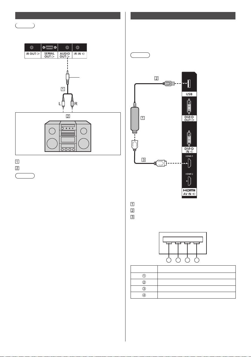
AUDIO OUT terminal connection
Note
●
Audio equipment and the cable shown are not
supplied with this set.
Stereo mini
plug (M3)
line-in
Stereo audio cable (commercially available)
Audio equipment
Note
●
To output sound from AUDIO OUT terminal of the
unit, be sure to set [Output select] in the [Sound]
menu to [AUDIO OUT]. (see page 40)
USB terminal connection
Connect the USB memory (commercially available) to
use “USB media player” or “Memory viewer”. (see page
95, 107)
Also, power is supplied when a separately sold stick PC,
etc. are connected.
Note
●
A stick PC and connection cables are not supplied
with this unit.
26
Stick PC
USB cable (commercially available)
HDMI extension cable (commercially available)
Pin assignments and signal names for USB Terminal
1 3 42
Pin No. Signal name
+5 V DC
DATA DATA +
GND (Ground)
English
Page 27

Power of up to 5V/1A can be supplied to an external
device when the picture is displayed.
●
If the electric current exceeding the power supplying
capability is applied, the output is blocked, and the
following message is displayed.
[USB DC5V OUT overload. Please remove cable or
equipment, then turn the display off/on.]
In this case, remove the equipment and then turn the
power off/on using the remote control, etc.
Note
●
If the direct connection to this unit is not possible due
to the size of a stick PC, etc. use a commercially sold
extension cable.
●
Depending on the type of a USB memory device,
it may come in contact with the periphery such
as a back cover, and cannot be attached. Use a
commercially sold extension cable, or use a small
type of a USB memory device connectable to this
unit.
●
When connecting the USB memory device, confirm
the orientation of the plug to prevent damage to the
terminal.
●
When removing the USB memory device, note the
following.
When the access indicator of the connected USB
•
memory device is blinking, it shows the display is
loading the data. Do not remove the USB memory
device while blinking.
Depending on the USB memory device, the access
•
indicator may remain blinking even when it is not
being accessed, or the device is not equipped
with an access indicator function, etc. In this case,
remove the USB memory device after confirming
the following or .
Switch the input to an input other than [USB]
and [MEMORY VIEWER], and confirm that the
functions that access USB memory device are
finished. The functions are, read user image
function (see page 54), playlist edit function (see
page 102), data cloning function (see page 114 ),
etc.
Turn the unit off.
Do not frequently repeat connecting/disconnecting
•
the USB memory device. Wait at least 5 seconds
after connection, and then remove the USB
memory device. Before reconnection, wait at least
5 seconds. A certain length of time is required
so that the display can recognise that the USB
memory device is switched for connection or
disconnection.
If the power of this unit is turned off or the USB
•
memory device is removed accidentally while
accessing data, the data may not be accessed
next time the USB memory device is used.
In such a case, turn the power of the main unit off
and on.
English
27
Page 28

Identifying Controls
65-inch model
55-inch model
Main unit
1
●
Slide the lever on the rear panel to eject the power
indicator and remote control sensor.
To store them, slide the same lever, or directly
push in the bottom surface of the remote control
sensor.
Note
●
For normal use, pull out the power indicator and
remote control sensor from the edge side of the
main unit by operating the lever on the rear panel.
Depending on the setup condition such as when
using the multi display, store them in the main unit.
1 Power Indicator / Remote control sensor
The Power Indicator will light.
When the power of the unit is ON (Main Power On
/ Off button: ON)
●
Picture is displayed: Green
●
Power OFF (standby) with remote control:
When [Network control] is set to [Off]: Red
•
When [Network control] is set to [On]: Orange
•
(Red/Green)
About [Network control] settings, see page 59.
●
Power OFF with “Power management” function:
Orange (Red/Green)
About “Power management” function, see page 51.
When the power of the unit is OFF (Main Power
On / Off button: OFF): No light
Note
●
Even if the display unit is turned off with the power
indicator off, some of the circuits are in power-on
status.
●
When the power indicator is orange, power
consumption during standby is generally larger than
that of when the power indicator is red.
INPUT
MENU
ENTER
1 External Input Terminal
Connects to video equipment, PC, etc. (see page 17)
2 <Main Power On / Off button>
Turns the power On / Off.
3 <INPUT (Unit)>
Selects the connected device. (see page 31)
4 <MENU (Unit)>
Displays the menu screen. (see page 36)
5 <+ (Unit)> / <- (Unit)>
Adjusts the volume. (see page 32)
On the main screen, switches settings or adjusts
settings level. (see page 36)
(Unit)> / < (Unit)>
6 <
Selects the setting item on menu screen. (see page
36)
7 <ENTER (Unit)>
Configures the item on menu screen. (see page 36)
Switches aspect mode. (see page 34)
8 Built-in speakers
Sound is output backward and upward.
49-inch model
43-inch model
Sound is output backward.
Note
●
To output sound from the built-in speakers of the
unit, be sure to set [Output select] in the [Sound]
menu to [SPEAKERS]. (see page 40)
65-inch model
55-inch model
49-inch model
43-inch model
8
8
8
8
English
28
Page 29

Remote Control Transmitter
1 Standby (ON/OFF) button ( / )
●
Turns the power on or off when the Display is
turned on at the <Main Power On / Off button>.
(see page 30)
2 POSITION
(see page 38)
3 SETUP
(see page 47)
4 ENTER / Cursor buttons (
●
Used to operate the menu screens. (see page 36)
5 ZOOM
Enters the digital zoom mode. (see page 35)
6 DEFAULT
●
Resets the settings of picture, sound, etc., to
defaults. (see page 38, 40, 41)
7 MUTE
●
Sound mute on / off. (see page 33)
8 ASPECT
●
Adjusts the aspect. (see page 34)
9 VOL + / VOL -
●
Adjusts sound volume level. (see page 32)
10 AUTO SETUP
●
Automatically adjusts the position/size of the
screen. (see page 38)
11 INPUT
●
Switches input to display on the screen. (see page
31)
12 PICTURE
(see page 41)
13 SOUND
(see page 40)
)
14 RECALL
●
Displays the current setting status of Input mode,
Aspect mode, etc. (see page 32)
15 RETURN
●
Used to return to the previous menu. (see page 36)
16 FUNCTION
●
Displays [Function button guide].
(see page 65)
17 OFF TIMER
●
Switches to stand-by after a fixed period. (see
page 33)
18 Numeric buttons (1 - 6)
●
Used as shortcut buttons by assigning frequently
used operations. (see page 64)
19 Signal emission
Note
●
In this manual, buttons of the remote control and the
unit are indicated as < >.
(Example: <INPUT>.)
The operation is mainly explained indicating the
remote control buttons but you can also operate with
the buttons on the unit when there are the same
buttons.
English
29
Page 30

Basic Controls
AC cord (supplied)
Main Power On / Off button
(Back of the unit)
Operate pointing the remote control directly at
the unit’s Remote Control Sensor.
Note
●
For normal use, pull out the remote control sensor
from the edge side of the main unit by operating the
lever on the rear panel. (see page 28)
●
Do not put an obstacle between the remote control
sensor of the main unit and the remote control.
●
Operate the remote control in front of the remote
control sensor or from the area where the sensor can
be seen.
●
When directly aiming the remote control at the remote
control sensor of the main unit, the distance from
the front of remote control sensor should be approx.
7 m or less. Depending on the angle, the operation
distance may be shorter.
●
Do not subject the remote control sensor of the main
unit to the direct sunlight or strong fluorescent light.
English
30
Remote Control Sensor /
Power Indicator
AC socket outlet
Connect the AC cord plug to the
1
Display.
(see page 15)
Connect the plug to the socket outlet.
2
Note
●
Main plug types vary between countries. The
power plug shown at left may, therefore, not be the
type fitted to your set.
●
When disconnecting the AC cord, be absolutely
sure to disconnect the AC cord plug at the socket
outlet first.
●
The settings may not be saved if the power plug is
disconnected immediately after changing settings
with on-screen menu. Disconnect the power plug
after a enough period of time. Or, disconnect the
power plug after turning the power off with the
remote control, RS-232C control or LAN control.
Press the <Main Power On / Off
3
button> on the unit to turn the set on:
Power-On.
●
Power Indicator: Green (Picture is displayed.)
●
When the power of the unit is ON, remote control
operation is possible.
■ To turn the power ON/OFF with the remote
control
Press the <Standby (ON/OFF) button> to turn the
Display on.
●
Power Indicator: Green (Picture is displayed.)
Press the <Standby (ON/OFF) button> to turn the
Display off.
●
Power Indicator: Red (standby)
Press the <Main Power On / Off button> on the unit to
turn the unit off, when the power of the unit is turned
on or in standby mode.
Note
●
During operation of the “Power management” function
(see page 51), the power indicator turns orange in the
power off state.
●
After the power plug is disconnected, the power
indicator may remain lit for a while. This is not a
malfunction.
Page 31
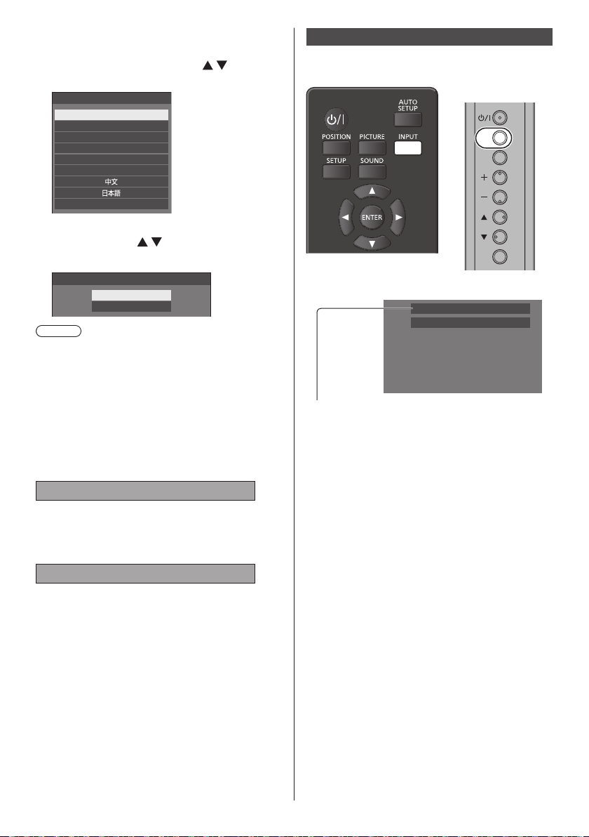
■ When the Unit is turned on for the first time
Following screen will be displayed.
Select the language with and
1
press <ENTER>.
OSD language
English (UK)
Deutsch
Français
Italiano
Español
ENGLISH (US)
Русский
For vertical installation, select
2
[Portrait] with and press
<ENTER>.
Display orientation
Landscape
Portrait
Note
●
Once the items are set, the screens won’t be
displayed when switching on the unit next time.
Each item can be reset in the following menus.
[OSD language] (see page 55)
[Display orientation] (see page 66)
■ Power ON message
The following message may be displayed when turning
the unit power ON:
No activity power off Precautions
’No activity power off’ is enabled.
When [No activity power off] in the [Setup] menu is set to
[Enable], a warning message is displayed every time the
power is turned ON. (see page 55)
“Power management” Information
Last turn off due to ’Power management’.
When “Power management” is functioned, an
information message is displayed every time the power
is turned ON. (see page 51)
These message displays can be set with the following
menu:
●
[Options] menu
Power on message(No activity power off)
(see page 75)
Power on message(Power management)
(see page 75)
Selecting the input signal
Select the signals input to the unit.
Press <INPUT> or <INPUT (Unit)>.
Unit
INPUT
MENU
ENTER
Switches input every time the buttons are pressed.
PC
16:9
[HDMI1] → [HDMI2] → [DIGITAL LINK] → [DVI-D] →
[PC] → [VIDEO] → [USB] → [MEMORY VIEWER]
*
DIGITAL LINK is for TH-65SF2E only.
[HDMI1]:
HDMI 1 terminal, HDMI input
[HDMI2]:
HDMI 2 terminal, HDMI input
[DIGITAL LINK]:
DIGITAL LINK / LAN terminal, DIGITAL LINK input
[DVI-D]:
DVI-D IN terminal, DVI-D input
[PC]:
PC IN terminal, PC input
[VIDEO]:
AV IN terminal, composite video input
[USB]:
USB terminal, USB input
[MEMORY VIEWER]:
USB terminal, “Memory viewer” input
English
31
Page 32
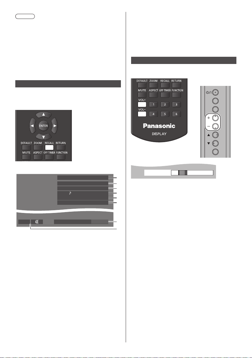
Note
●
Displays the signal name as set in [Input label]. (see
page 51)
●
Input will not be switched unless [Input lock] is set to
[Off]. (see page 72)
●
Image retention (image lag) may occur on the LCD
liquid crystal panel when a still picture is kept on
the panel for an extended period. To prevent such
a problem, using the screensaver and wobbling is
recommended. (see page 50, 55)
RECALL
It is possible to check the setting status of input label,
picture mode, etc.
Press <RECALL>.
●
When [No signal image settings] - [Display setting] is
set to [On] (see page 54), the message [No signal] /
[No external media] / [No play file] are not displayed.
Instead, the image set in [No signal image settings]
will be displayed.
●
To display the clock, set [Date and time] and then set
[Clock display] to [On]. (see page 57, 75)
Volume Adjustment
Press <VOL +> <VOL -> or <+ (Unit)> <- (Unit)> to
adjust volume.
Unit
INPUT
MENU
ENTER
Current setting status will be displayed.
HDMI1
16:9
Backup mode OK
AV IN
Memory name: MEMORY2
Schedule play mode
10:00
Off timer
90 min
1 Input label
2 Aspect mode (see page 34)
3 Backup input change (see page 70, 71)
4 Audio input (see page 71)
5 Profile name (see page 46)
6 [Schedule play mode] (see page 103)
7 Off timer remaining time (see page 33)
8 Clock / Mute (see page 33, 75)
●
When there is no video signal to the selected input,
[No signal] is displayed for about 30 seconds at the
end.
●
When a USB memory is not connected to the USB
terminal at the time of switching to the USB input, [No
external media] is displayed for about 30 seconds.
Even when a USB memory is connected, if it does not
contain any playable file, [No play file] is displayed at
all times.
Volume (SPEAKERS)
20
1
2
●
3
4
5
6
7
8
The current sound volume level is memorised even if
the power is turned off.
●
When [Maximum VOL function] is set to [On], the
volume can only be adjusted to the maximum point
you set, and the displayed value turns red when it
reached its maximum. (see page 72)
●
When [Initial VOL function] is set to [On], the volume
will be at the set level when the display is turned on.
(see page 72)
32
English
Page 33
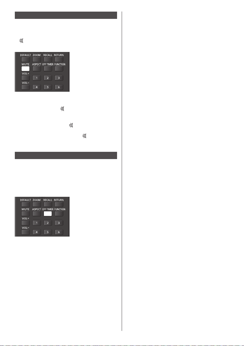
Sound mute On / Off
It is useful when you want to mute the sound temporarily,
for example, when answering the phone or door.
Press <MUTE>.
●
appears on the screen and the sound is muted.
Press again to reactivate the sound.
●
It is also reactivated when the power is turned on / off
or the volume level is changed.
●
While MUTE is active,
after operation.
●
When the image set in [No signal image settings]
(see page 54) is displayed,
operation.
●
In [ENGLISH(US)] OSD language,
[MUTE].
is displayed as a reminder
is not displayed after
is displayed as
OFF TIMER
The Display can be preset to switch to stand-by after a
fixed period. (30 min, 60 min, 90 min)
The setting switches each time <OFF TIMER> is
pressed.
●
[0 min]→[30 min]→[60 min]→[90 min]
→[0 min] (Cancel)
●
When three minutes remain, the remaining time will
flash (Red). After that, it switches to stand-by.
●
To see the Off timer remaining time, press
<RECALL>.
●
The Off timer is cancelled if a power interruption
occurs. When the power is turned on later on, it will
be in stand-by condition.
●
When the image set in [No signal image settings] (see
page 54) is displayed, remaining time is not displayed
even when the timer expires in 3 minutes. Instead,
the image is displayed until the power is turned off.
Press <RECALL> to check the remaining time.
English
33
Page 34
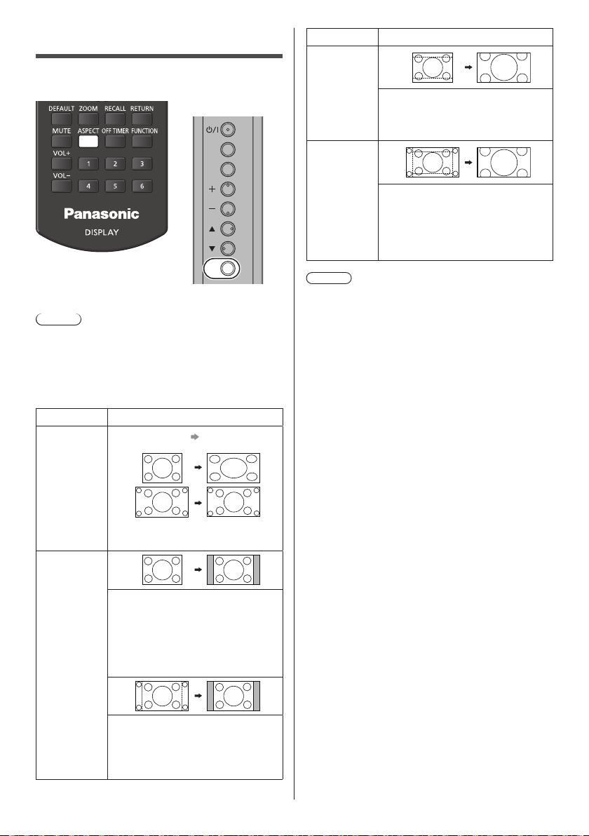
ASPECT Controls
Press <ASPECT> or <ENTER (Unit)> repeatedly to
move through the aspect options:
Unit
INPUT
MENU
Aspect mode Description
Zoom1
Letterbox pictures with a 16:9 aspect
ratio are enlarged vertically to fill the
screen. The top and bottom edges of
the pictures are cut off.
ENTER
[4:3]→[Zoom1]→[Zoom2]→[16:9]
Note
●
The aspect mode is memorised separately for each
input terminal.
●
When input from USB or MEMORY VIEWER, the
aspect mode is fixed to [16:9].
■ List of Aspect Modes
Aspect mode Description
Enlarged
screen
16:9
4:3
Picture
Pictures are displayed filling the
screen.
Pictures are displayed in the 4:3
area. Pictures with a 4:3 aspect ratio
are displayed as is. PC signals are
enlarged or reduced to be displayed
in the 4:3 area. Side panels are
displayed both at the right and left
edges of the screen.
Zoom2
Note
●
Be aware that if you put the display in a public place
for commercial purposes or a public showing and
then use the aspect mode select function to shrink
or expand the picture, you may be violating the
copyright under copyright law. It is prohibited to show
or alter the copyrighted materials of other people for
commercial purposes without the prior permission of
the copyright holder.
●
In [ENGLISH(US)] OSD language, [16:9] is displayed
as [FULL].
Letterbox pictures with a 16:9 aspect
ratio are enlarged vertically and
horizontally to fill the screen. The top
and bottom edges as well as the left
and right edges of the pictures are
cut off.
34
Pictures with a 4:3 aspect ratio in
16:9 signals are displayed with their
original aspect ratio. The left and right
edges of the pictures are masked by
side panels.
English
Page 35
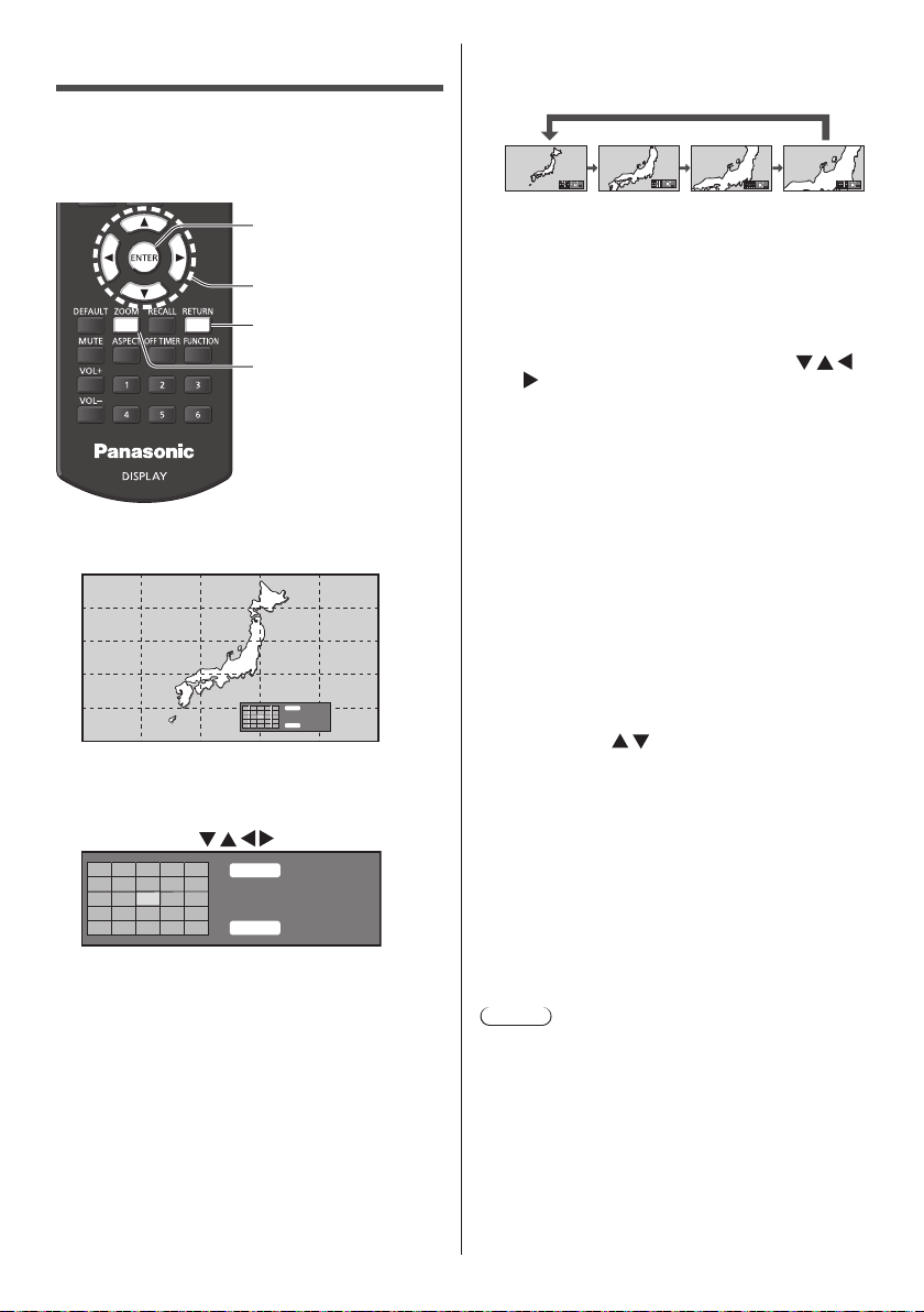
Digital ZOOM
Select the screen areas (25 areas) to zoom in, and
zoom in the selected image areas ×2, ×3 or ×4.
(Use the remote control. The main unit’s buttons cannot
be used for operation.)
Enter
Select
Exit
Digital Zoom
Set the digital zoom mode.
1
Press <ZOOM>.
Exit
RETURN
×1
ENTER
The screen aspect is set to [16:9], and the digital
zoom operation guide is displayed.
Select the image areas to zoom in.
2
Select pressing .
RETURN
ENTER
Digital Zoom operation guide
Exit
×1
Switch the zoom ratio for the screen
3
areas.
Switches every time <ENTER> is pressed.
Exit
×1
×1 ×2 ×3 ×4
●
If no operation is performed for the period set for
[Menu display duration] (see page 66)(5‒180
seconds) when the zoom ratio for the screen is
“×1”, the unit exits the zoom mode.
●
If no operation is performed for approx. 3 seconds
when the zoom ratio for the screen is “×2”,
“×3” or “×4”, the digital zoom operation guide
display disappears. Pressing any of the
buttons displays the guide again.
Exit the digital zoom mode.
4
Press <RETURN> to exit the mode.
The screen returns to the previous state just before
entering the digital zoom mode, and the digital zoom
operation guide display disappears.
●
Press any of the following buttons to exit the
mode. Then, the operation of the pressed button
is performed.
Remote Control:
<AUTO SETUP> <POSITION> <PICTURE>
<INPUT> <SETUP> <SOUND>
<DEFAULT> <RECALL> <MUTE>
<ASPECT> <OFF TIMER> <FUNCTION>
<VOL +> <VOL -><1>‒<6>
Unit:
<INPUT (Unit)> <MENU (Unit)> <+ (Unit)>
<- (Unit)>
●
When the screen saver timer starts up, the digital
zoom mode finishes.
●
When the power is turned OFF, a force-quit is
performed.
When the power is turned OFF by pressing the
•
<Standby (ON/OFF) button>.
When the display is turned OFF at the <Main
•
Power On / Off button>
When the power is turned OFF by the off-timer
•
When the power is turned OFF by [No signal
•
power off] or “Power management”.
Exit
×2
<ENTER (Unit)>
Exit
×3
Exit
×4
Note
●
In the following cases, the digital zoom mode is not
available.
When [Multi display setting] is [On]
•
When the screen saver is in operation
•
When USB input or MEMORY VIEWER input is
•
selected.
●
The zoomed image is rougher than the original
image.
●
For multi display use, use the functions in [Multi
display settings]. (see page 56)
English
35
Page 36
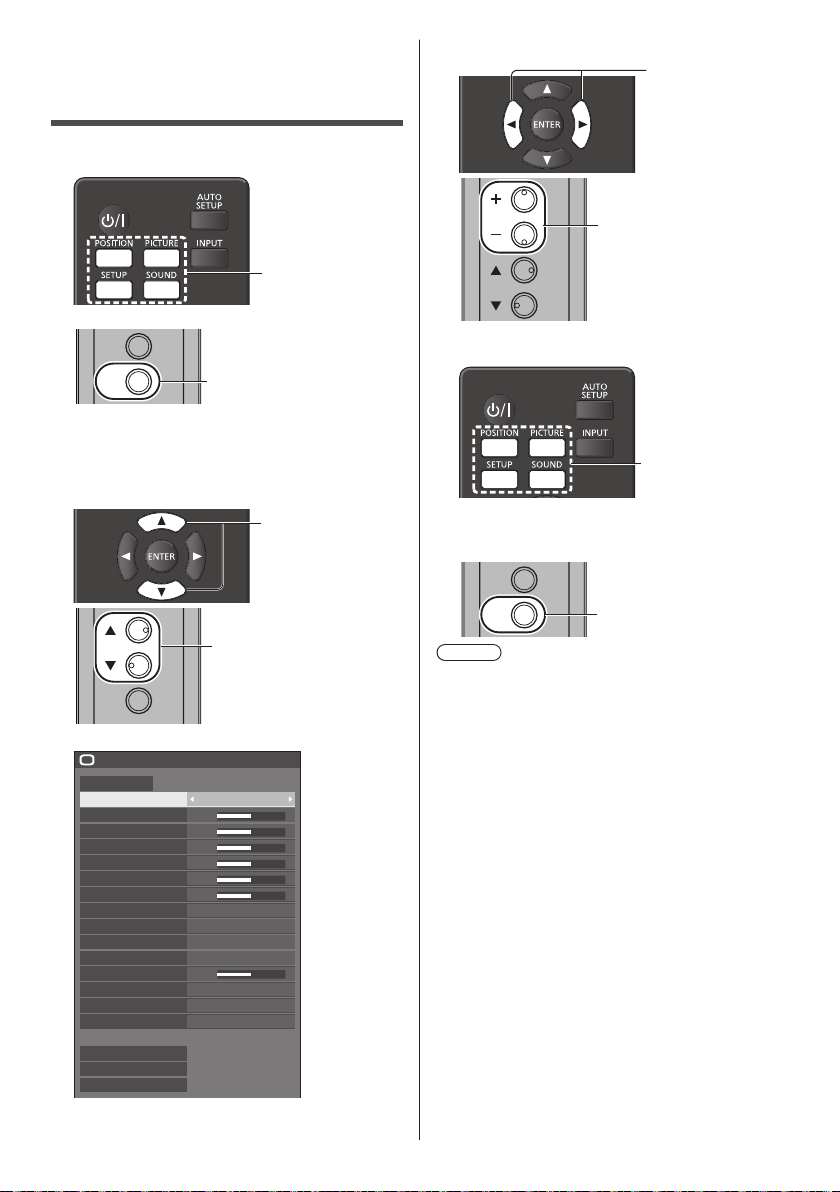
On-Screen Menu Displays
Display the menu screen.
1
Remote Control
Press to select.
Unit
INPUT
MENU
Each time the button is pressed, the menu screen
will switch.
NormalViewing→[Picture]→[Setup]→[Position]
→[Sound]
Select the item.
2
Press for several times.
Press to select.
Set.
3
Press to set.
Press to set.
Exit from the menu.
4
Press.
Press <RETURN> to return to the previous screen.
Alternatively, press the button selected in step 1 to
exit from the menu.
INPUT
ENTER
(Example: [Picture] menu)
Picture
Default Default
Picture mode Standard
Backlight
Contrast
Brightness
Colour
Hue
Sharpness
Gamma
6-segment colour management
Dynamic contrast
Colour enhancement
Refine enhancer
Gradation smoother
Memory save
Memory load
Memory edit
50
50
50
50
50
50
5
To display the submenu, press <ENTER>.
English
36
Press to select.
HighEnhance level
2.2
6500KColour temperature
Off
Off
Off
Off
MENU
Press for several times.
Note
●
When changing the settings of the display, picture or
sound disturbance may occur temporarily. This is not
a malfunction.
Page 37
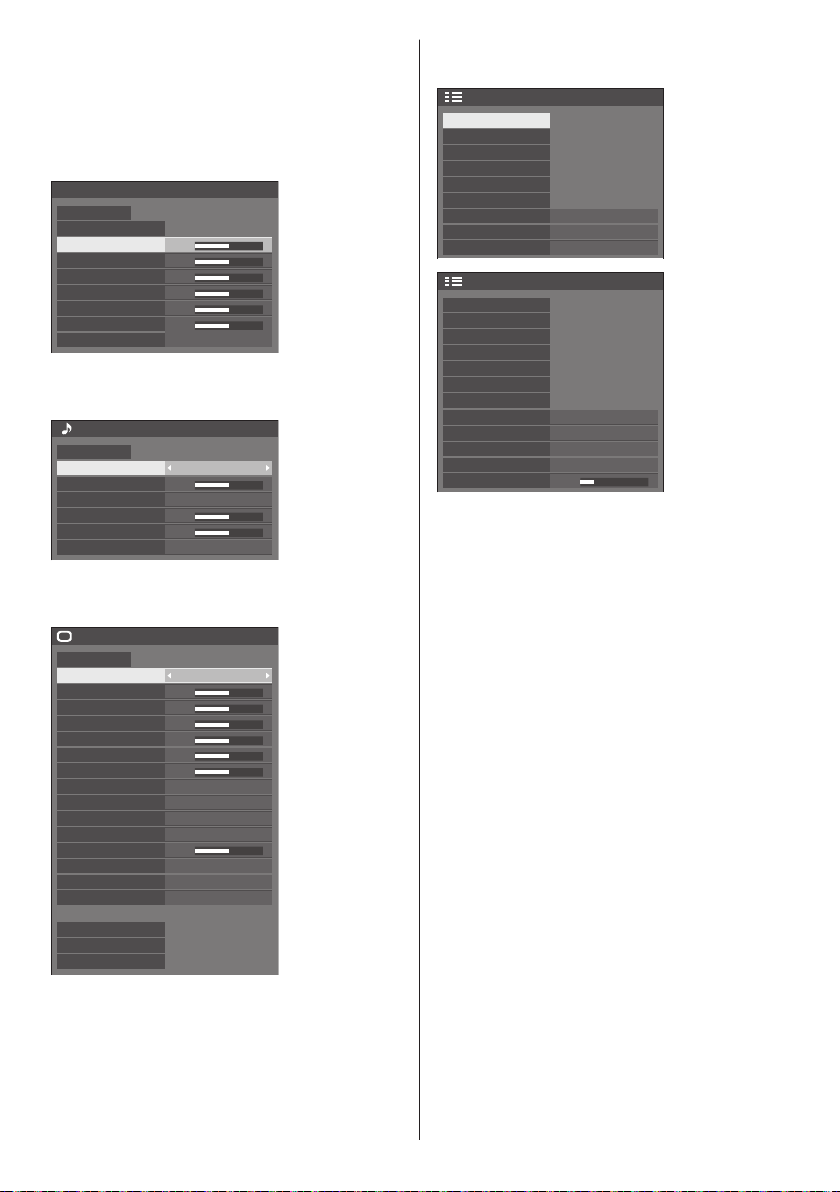
Menu display list
●
Menu that cannot be adjusted is greyed out.
Adjustable menu changes depending on signal, input
and menu setting.
[Position] menu
(see page 38‒39)
Position
Default Default
Auto setup
H-position
H-size
V-position
V-size
Clock phase
Dot clock
1:1 pixel mode
0
0
0
0
15
0
Off
[Sound] menu
(see page 40)
Sound
Default Default
Output select SPEAKERS
Balance
Sound mode
Bass
Treble
Surround
0
Normal
0
0
Off
[Picture] menu
(see page 41‒46)
Picture
Default
Default
Picture mode Standard
Backlight
Contrast
Brightness
Colour
Hue
Sharpness
Enhance level High
Gamma
Colour temperature 6500K
6-segment colour management
Dynamic contrast
Colour enhancement
Refine enhancer
Gradation smoother
Memory save
Memory load
Memory edit
50
50
50
50
50
50
2.2
Off
5
Off
Off
Off
[Setup] menu
(see page 47‒66)
Setup
Signal
Screensaver
Input label
Power management settings
HDMI-CEC settings
Image settings
Wobbling
No activity power off
OSD language
Setup
Multi display settings
Set up timer
Date and time
Network settings
USB media player settings
Memory viewer settings
Function button settings
Display orientation
Image rotation
OSD position
Menu display duration
Menu transparency
English(UK)
Landscape
20
Off
Disable
Off
Right
60 sec
1/2
2/2
English
37
Page 38
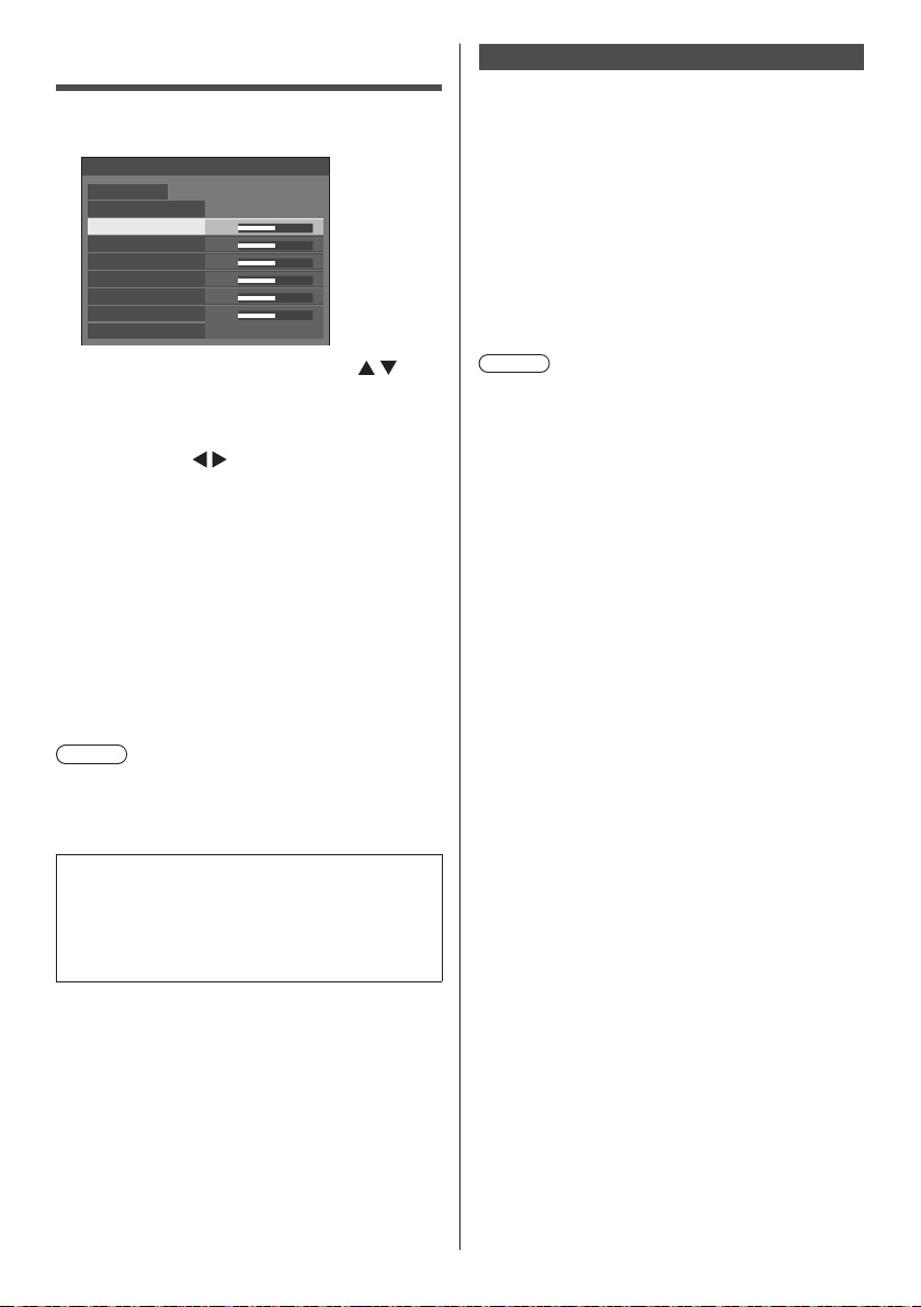
Adjusting Position
Press <POSITION> to display the
1
[Position] menu.
Position
Default Default
Auto setup
H-position
H-size
V-position
V-size
Clock phase
Dot clock
1:1 pixel mode
Select the item to adjust with .
2
●
Unadjustable items are greyed out.
Adjustable items differ depending on the signal,
input and the display mode.
Adjust with .
3
Press <POSITION> to exit from adjust
4
mode.
■ To return to the previous screen
Press <RETURN>.
■ To reset to defaults
When [Default] is selected, pressing <ENTER> resets
the adjustment values of all the displayed menus to
default.
When adjusting each item, pressing <DEFAULT>
resets the adjustment value of the item to default.
Note
●
Settings for [Position] are memorised separately for
each input signal.
●
With MEMORY VIEWER input, each item in the
[Position] menu cannot be adjusted.
Setting [Position] when the display is installed
vertically
When adjusting, please note that even when the
display is installed vertically, setting directions of
position / size are the same as that of horizontal
installation.
0
0
0
0
15
0
Off
Auto setup
When inputting a PC signal, [H-position] / [V-position],
[H-size] / [V-size], [Clock phase] and [Dot clock] are
automatically corrected.
This setting is enabled under the following
condition:
●
When inputting an analogue signal (PC).
While displaying the picture of the corresponding
signal, select [Auto setup] and press <ENTER>.
Using Remote Control
Press <AUTO SETUP>.
When Auto Setup does not work, [Invalid] is
displayed.
Note
●
When the dot clock frequency of a PC signal is 162
MHz or higher, [Clock phase] and [Dot clock] cannot
be automatically corrected.
●
Auto Setup may not work when a cropped or dark
image is input. In such case, switch to a bright image
with borders and other objects are clearly shown, and
then try auto setup again.
●
Depending on the signal, out of alignment may occur
after Auto Setup. Carry out fine tuning for the position/
size as required.
●
If Auto Setup cannot set properly for XGA signal
(1024 x 768, 1280 x 768, 1366 x 768), pre-selecting
the individual signal in [XGA mode] (see page 48)
may result in correct Auto Setup.
●
Accurate auto setup is not possible when a signal
such as additional information is superimposed out
of valid image period or when intervals between
synchronizing signal and image signal are short.
Also, accurate auto setup is not possible when image
signals with tri level synchronizing signal added, or
when some SYNC ON G signals are input.
●
When the [PC auto setting] is set to [On] in the
[Options] menu (see page 73), automatic position
adjustment starts under the following conditions:
When the display power is turned ON.
•
When the input signal is switched.
•
●
If Auto Setup does not work well, select [Default],
press <ENTER>, and then adjust the position/size
manually.
38
English
Page 39
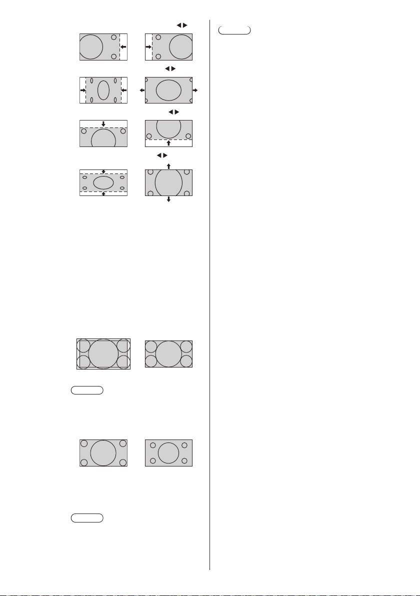
[H-position] Adjust the horizontal position with .
[H-size] Adjust the horizontal size with
[V-position] Adjust the vertical position with .
[V-size] Adjust the vertical size with .
.
Note
●
In some cases, noise appears outside the area
picture is displayed, but it is not a malfunction.
[Clock
phase]
[Dot clock] (For PC IN input)
[Over scan] Turn image over scan On/Off.
[1:1 pixel
mode]
(For PC IN input)
In some cases, frame of the screen
appears blurred or smudged, when PC
signal is input.
Periodic striped pattern interference
(noise) may occur when a striped pattern
is displayed. If this happens, adjust so
that any such noise is minimized.
Applicable input signal:
480/60i, 480/60p, 576/50i, 576/50p,
720/60p, 720/50p
[On] [Off]
Note
●
When [Off] is set, [H-size] and [V-size]
cannot be adjusted.
Adjusts the display size when 1080i or
1080p signal is input.
[Off] [On]
Applicable input signal:
1080 / 50i, 60i, 24PsF, 24p, 25p, 30p,
50p, 60p
Note
●
Select [Off] when flickering is shown
around the image.
●
[H-size] and [V-size] cannot be
adjusted when [On] is selected.
English
39
Page 40
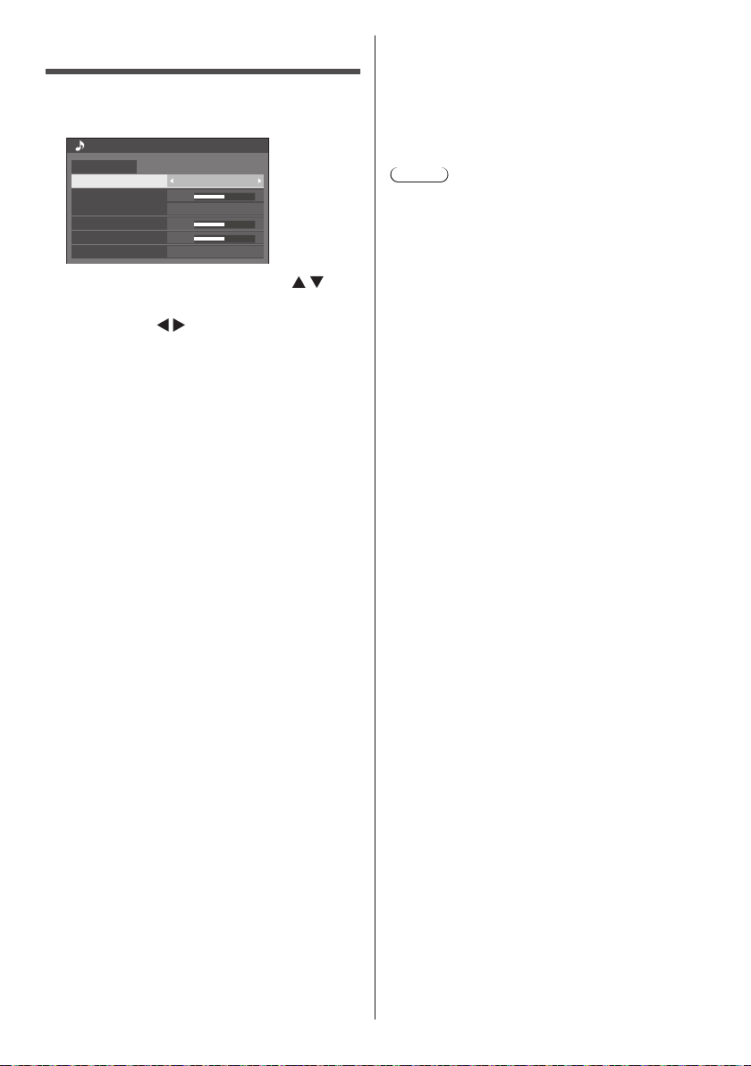
Sound Adjustment
Press <SOUND> to display the
1
[Sound] menu.
Sound
Default Default
Output select SPEAKERS
Balance
Sound mode
Bass
Treble
Surround
Select the item to adjust with .
2
●
Menu that cannot be adjusted is greyed out.
Adjust with .
3
Press <SOUND> to exit from adjust
4
mode.
■ To return to the previous screen
Press <RETURN>.
■ To reset to defaults
Press <DEFAULT> while the menu is displayed, or
press <ENTER> when [Default] is selected, then the
adjustment values of all the displayed menus are
reset to default.
[Output select] Select the audio output.
[Balance] Adjusts left and right volumes.
[Sound mode] Select for best audio.
●
In [ENGLISH(US)] OSD language, [Sound mode]
and [Normal] are displayed as [AUDIO MENU] and
[STANDARD].
0
Normal
0
0
Off
[SPEAKERS]:
Internal speakers
[AUDIO OUT]:
AUDIO OUT terminal output
●
When [AUDIO OUT] is selected,
the other menus are greyed out
and cannot be selected.
●
Audio volume setting is
memorized separately for each
output.
[Normal]:
Emits the original sound.
[Dynamic]:
Accentuates sharp sound.
[Clear]:
Attenuates human voice.
[Bass] Adjusts low pitch sounds.
[Treble] Adjusts high pitch sounds.
[Surround] [Off]:
Normal sound
[On]:
Surround sound
Note
●
[Bass], [Treble] and [Surround] settings are
memorised separately for [Normal], [Dynamic] and
[Clear] in [Sound mode].
40
English
Page 41
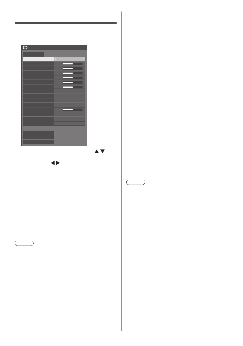
Picture Adjustments
Press <PICTURE> to display the
1
[Picture] menu.
Picture
Default Default
Picture mode Standard
Backlight
Contrast
Brightness
Colour
Hue
Sharpness
Gamma
Colour temperature
6-segment colour management
Dynamic contrast
Colour enhancement
Refine enhancer
Gradation smoother
Memory save
Memory load
Memory edit
Select the item to adjust with .
2
●
Menu that cannot be adjusted is greyed out.
Adjust with .
3
Press <PICTURE> to exit from adjust
4
mode.
■ To return to the previous screen
Press <RETURN>.
■ To reset to defaults
When [Default] is selected, pressing <ENTER> resets
the adjustment values of all the displayed menus to
default.
When adjusting each item, pressing <DEFAULT>
resets the adjustment value of the item to default.
Note
●
When displaying still pictures with the USB input
(USB media player) or displaying the thumbnail
screen or file list screen of the MEMORY VIEWER
input (Memory viewer) (see page 109), only the
following settings have an effect on the picture.
[Backlight], [Gamma], [Colour temperature]
50
50
50
50
50
50
HighEnhance level
2.2
6500K
Off
5
Off
Off
Off
[Picture mode] This menu switches to easy-to-
see pictures suitable to the picture
source or environment where this
unit is used.
[Vivid signage]:
Suitable for signage applications
featuring more vivid and sharper
images in bright environments such
as a shop.
[Natural signage]:
Suitable for signage applications
such as merchandise exhibition,
featuring natural tone images with
colour reproduction emphasized
under light.
[Standard]:
Faithfully reproduces original
picture.
[Surveillance]:
Tone-focused pictures with
brightness reduced suitable for input
from a monitoring camera.
[Graphic]:
Suitable for PC input.
[DICOM]:
Pictures close to the grayscale
standard DICOM Part14.
●
The settings are memorised
separately for each input
terminal.
Note
●
DICOM is the abbreviation for “Digital Imaging and
Communications in Medicine”, which is a standard for
communications between medical imaging devices.
Although “DICOM” is used as a picture mode name,
this unit is not a medical device. Do not use displayed
images for such purposes as diagnosis.
●
In [ENGLISH(US)] OSD language, [Picture mode] is
displayed as [PICTURE MENU].
[Backlight] Adjusts luminance of the back light.
Darker ↔ Brighter
[Contrast] Selects the proper brightness and
density for the room.
Less ↔ More
●
In [ENGLISH(US)] OSD language, [Contrast] is
displayed as [PICTURE].
[Brightness] Adjusts for easier viewing of dark
pictures.
Darker ↔ Brighter
[Colour] Adjusts colour saturation.
Less ↔ More
[Hue] Adjusts hue of skin colour.
Reddish ↔ Greenish
●
In [ENGLISH(US)] OSD language, [Hue] is displayed
as [TINT].
English
41
Page 42
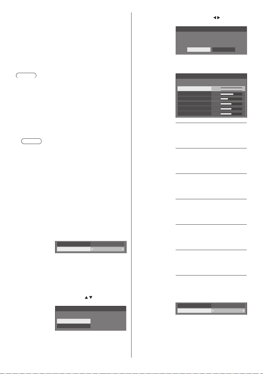
[Sharpness] Adjusts picture sharpness.
Less ↔ More
[Enhance level] Switches the effect range for
sharpness.
[High]: Large effect
[Low]: Small effect
[Gamma] Adjusts gamma.
[2.0], [2.2], [2.4], [2.6], [DICOM]:
Small tilt - Large tilt
Note
●
When [DICOM] is selected in [Picture mode],
[Gamma] is fixed to [DICOM].
When the items other than [DICOM] are selected in
[Picture mode], [DICOM] cannot be set for [Gamma].
[Colour
temperature]
Adjusts colour tone.
[3200K], [4000K], [5000K],
[6500K], [7500K], [9300K],
[10700K], [Native], [USER1],
[USER2]
Note
●
Emphasizes red when the numerical value of
[Colour temperature] is small, and emphasizes
blue when it is big.
●
[Native] is a colour tone of the panel element.
When this is selected, [Gamma] is fixed to 2.2 or
equivalent and it cannot be adjusted.
●
When [DICOM] is selected in [Picture mode], only
[6500K] and [9300K] can be selected.
User setting of [Colour
temperature]
2 kinds of detailed [Colour
temperature] settings ([USER1]
and [USER2]) can be stored.
1 Press <ENTER> while setting
[Colour temperature].
Gamma
Colour temperature
2.2
6500K
Example:
When [Colour temperature] is
[6500K], it is possible to reflect
the set point, [6500K], to the set
point of [USER1] and [USER2].
2 Select the user to memorise
settings with
and press
<ENTER>.
Adjust colour temperature
Change to 6500K
USER1
USER2
[6-segment
colour
management]
3 Select [Ye s] with and press
<ENTER>.
Adjust colour temperature
Overwrite colour temperature “USER1”?
Yes No
4 Set each item on detail settings
screen.
Adjust colour temperature
USER1
R gain
G gain
B gain
R bias
G bias
B bias
255
150
64
0
0
0
[R gain]
Adjusts the white balance for light
red areas.
0 ‒ 255
[G gain]
Adjusts the white balance for light
green areas.
0 ‒ 255
[B gain]
Adjusts the white balance for light
blue areas.
0 ‒ 255
[R bias]
Adjusts the white balance for dark
red areas.
-127 ‒ 128
[G bias]
Adjusts the white balance for dark
green areas.
-127 ‒ 128
[B bias]
Adjusts the white balance for dark
blue areas.
-127 ‒ 128
The settings are saved for the user.
When you return to [Picture] menu,
the user you have set is selected for
[Colour temperature].
Gamma
Colour temperature
2.2
USER1
Adjusts the colour tone of R
(red), G (green), B (blue) and
complementary colours (cyan,
magenta and yellow) on the screen
individually.
42
English
Page 43
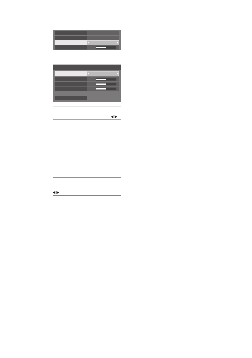
1 Set [6-segment colour
management] to [On], and then
press <ENTER>.
Gamma
Colour temperature
6-segment colour management
Dynamic contrast
5
2 Set each item on detail settings
screen.
6-segment colour management
Select colour Red
Hue
Saturation
Value
Reset
0
0
0
[Select colour]
Select the colour to adjust with
[Hue]
Adjusts colour balance.
- 511 to + 511
[Saturation]
Adjusts gradations of colour.
- 127 to + 127
[Value]
Adjusts brightness of colour.
- 127 to + 127
[Reset]
Resets to defaults. Select [Yes ] with
and press <ENTER>.
●
In [ENGLISH(US)] OSD language, [Hue] is
displayed as [TINT].
2.2
6500K
On
.
[Dynamic
contrast]
[Colour
enhancement]
[Refine
enhancer]
[Gradation
smoother]
Automatically adjusts the contrast by
determining the changes in the use
of colours for images that constantly
change, such as motion pictures.
No effect ↔ Large effect
Displays images by emphasising
colours.
[Off], [Low], [Mid], [High]
(Small effect to Large effect)
Enhances the sense of resolution by
correcting fuzzy outlines of pictures
resulted from resizing, etc.
[Off], [Low], [Mid], [High]
(Small effect to Large effect)
Extracts and eliminates noise
components from the input video
signals, and then displays noiseless
pictures.
[Off], [On]
English
43
Page 44
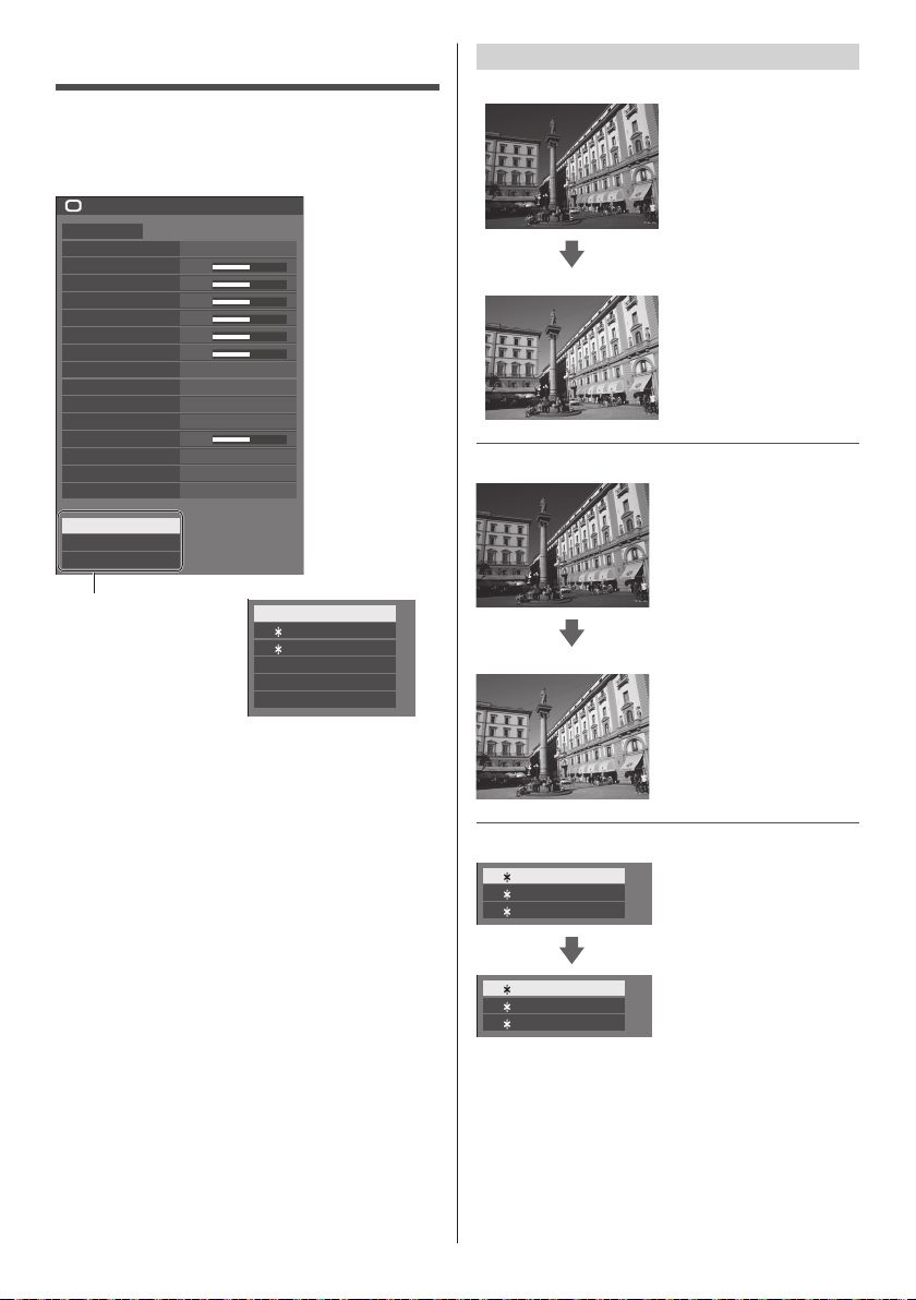
Picture Profiles
Up to 6 combinations of picture adjustment values (in
the [Picture] menu) can be stored in the display memory
as profiles and applied as needed, for a convenient way
to enjoy your preferred picture settings.
Picture
Default Default
Picture mode Standard
Backlight
Contrast
Brightness
Colour
Hue
Sharpness
Enhance level
Gamma
Colour temperature
6-segment colour management
Dynamic contrast
Colour enhancement
Refine enhancer
Gradation smoother
Memory save
Memory load
Memory edit
50
50
50
50
50
50
High
2.2
6500K
Off
5
Off
Off
Off
Overview of Picture Profiles
Original picture
Custom picture
Original picture
Adjust picture.
(see page 41‒43)
Example:
Save the picture adjustment
values in the [MEMORY1]
profile.
[Memory save]
Example:
Load [MEMORY1].
[Memory load]
[Memory save]
(see page 45)
[Memory load]
(see page 45)
[Memory edit]
(see page 46)
MEMORY1
1. [ ]
MEMORY2
2. [ ]
MEMORY3
3. [ ]
4. [ ] MEMORY4
5. [ ] MEMORY5
6. [ ] MEMORY6
Custom picture
[Memory edit] screen
MEMORY1
1. [ ]
MEMORY2
2. [ ]
MEMORY3
3. [ ]
MY PICTURE
1. [ ]
MEMORY2
2. [ ]
MEMORY3
3. [ ]
Example:
Change the memory name
to [MY PICTURE].
[Memory edit]
44
English
Page 45
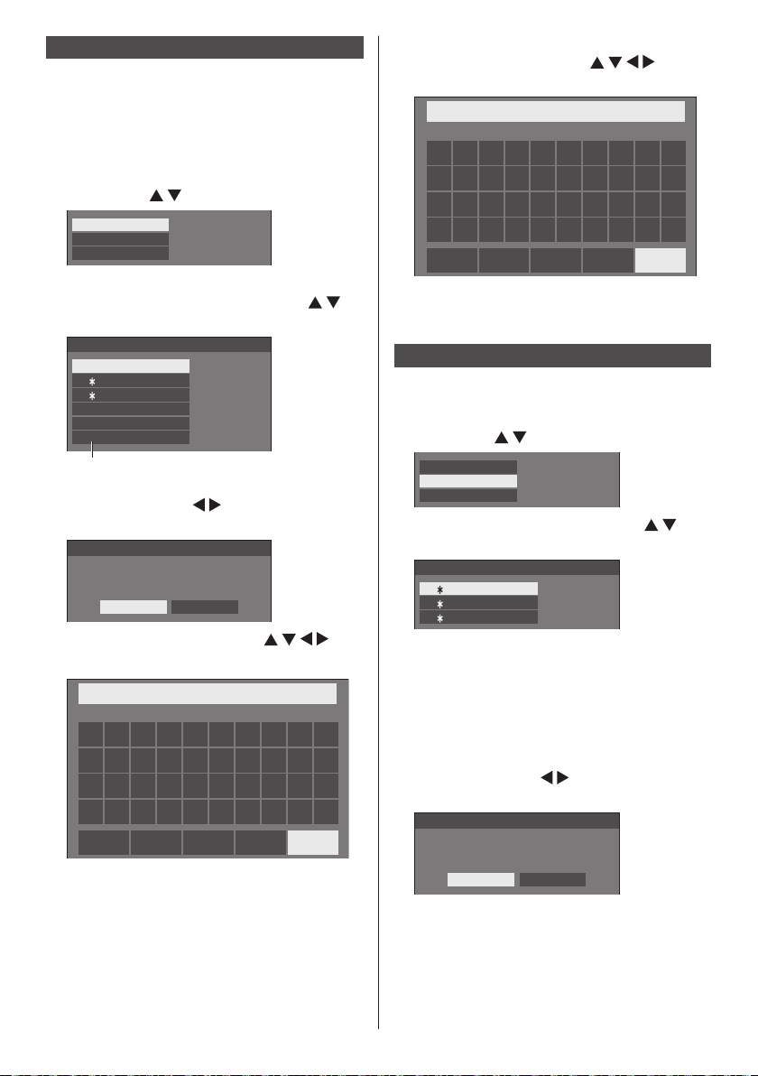
Saving profiles
Follow these steps to save picture adjustment values as
profiles.
Specify the picture quality in the
1
[Picture] menu.
(see page 41‒43)
In the [Picture] menu, select [Memory
2
save] with and press <ENTER>.
Memory save
Memory load
Memory edit
Select a profile name for saving the
3
picture adjustment values with
and press <ENTER>.
Memory save
MEMORY1
1. [ ]
MEMORY2
2. [ ]
MEMORY3
3. [ ]
4. [ ] MEMORY4
5. [ ] MEMORY5
6. [ ] MEMORY6
●
] appears for a profile in which the picture
[
*
adjustments have already been saved.
Select [Ok] with and press
4
<ENTER>.
Memory save
Save the adjusted value in ”MEMORY1”
Ok Cancel
Enter a profile name with .
5
●
Entering characters (see page 120)
█
MEMORY1
1 2 3 4 5 6 7 8 9
a
b c d e f g h i j
k l m
u v w x y z
n o p q r s t
a/A/@
0
–
_.
OkCancelAll deleteDelete
When you finished entering the profile
6
name, select [Ok] with and
press <ENTER>.
MY MEMORY1
●
To cancel saving the profile, select [Cancel].
█
1 2 3 4 5 6 7 8 9
a b c d e f g h i j
k l m
u v w x y z
n o p q r s t
–
_.
a/A/@
OkCancelAll deleteDelete
0
Loading profiles
Load profiles and apply the picture adjustment values to
the display as follows.
In the [Picture] menu, select [Memory
1
load] with and press <ENTER>.
Memory save
Memory load
Memory edit
Select the profile to load with and
2
press <ENTER>.
Memory load
MEMORY1
1. [ ]
MEMORY2
2. [ ]
MEMORY3
3. [ ]
Loading profiles using numeric buttons on the
remote control.
Eachnumericbutton<1>‒<6>isallocatedfor
loading [MEMORY1] to [MEMORY6].
[Function button settings] (see page 64)
Press any of <1> ‒ <6>.
1
Select [Ok] with and press
2
<ENTER>.
Memory load
Load from “MEMORY2”
Ok Cancel
English
45
Page 46
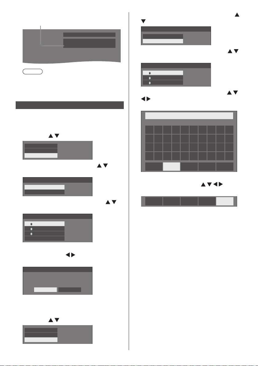
When profile is being loaded, profile name is
displayed.
PC
16:9
Memory name: MEMORY2
Note
●
Loaded profiles are stored in memory according
to the selected input terminal.
Editing profiles
Delete or rename profiles as follows.
■ Deleting profiles
In the [Picture] menu, select [Memory
1
edit] with and press <ENTER>.
Memory save
Memory load
Memory edit
Select [Memory delete] with and
2
press <ENTER>.
Memory edit
Memory delete
Memory name change
Select the profile to delete with
3
and press <ENTER>.
Memory delete
MEMORY1
1. [ ]
MEMORY2
2. [ ]
MEMORY3
3. [ ]
All delete
●
To delete all profiles, select [All delete].
Select [Ok] with and press
4
<ENTER>.
Memory delete
Select [Memory name change] with
2
and press <ENTER>.
Memory edit
Memory delete
Memory name change
Select the profile to rename with
3
and press <ENTER>.
Memory name change
MEMORY1
1. [ ]
MEMORY2
2. [ ]
MEMORY3
3. [ ]
Enter a name for the profile with
4
.
●
Entering characters (see page 120)
█
MEMORY1
1 2 3 4 5 6 7 8 9
a b c d e f g h i j
k l m
u v w x y z
When you finished entering the profile
5
n o p q r s t
–
_.
a/A/@
OkCancelAll deleteDelete
name, select [Ok] with and
press <ENTER>.
a/A/@
●
To cancel renaming the profile, select [Cancel].
OkCancelAll deleteDelete
0
Delete the ”MEMORY1” data
Ok Cancel
■ Renaming profiles
In the [Picture] menu, select [Memory
46
1
edit] with
English
Memory save
Memory load
Memory edit
and press <ENTER>.
Page 47
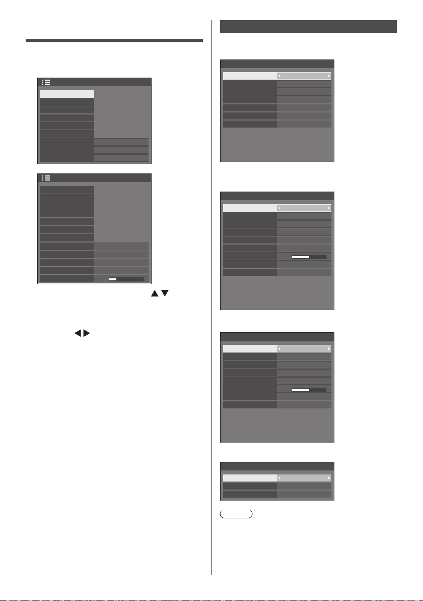
Setup menu
Press <SETUP> to display the [Setup]
1
menu.
Off
Disable
1/2
Setup
Signal
Screensaver
Input label
Power management settings
HDMI-CEC settings
Image settings
Wobbling
No activity power off
OSD language
English(UK)
Signal
Examples of [Signal] submenu screen
When HDMI / DVI / DIGITAL LINK is selected
Signal
YUV/RGB-in select
Cinema reality
Noise reduction
MPEG noise reduction
Signal range
Frame creation
Dynamic backlight control
H-freq.
V-freq.
Dot clock freq.
Signal format
YUV
Auto
Full(0-255)
33.72 kHz
60.00 Hz
74.18 MHz
1080/60i
Off
Off
Off
Off
Off
Right
60 sec
2/2
Setup
Multi display settings
Set up timer
Date and time
Network settings
USB media player settings
Memory viewer settings
Function button settings
Display orientation
Image rotation
OSD position
Menu display duration
Menu transparency
Select the item to set with .
2
●
Menu that cannot be adjusted is greyed out.
Landscape
20
Adjustable menu changes depending on signal
input and menu setting.
Set with .
3
Press <SETUP> to exit from adjust
4
mode.
■ To return to the previous screen
Press <RETURN>.
When PC is selected
Signal
Component/RGB-in select
Sync
Cinema reality
Noise reduction
MPEG noise reduction
XGA mode
Input level
Frame creation
Dynamic backlight control
H-freq.
V-freq.
Dot clock freq.
Signal format
RGB
Auto
Auto
Auto
0
33.72 kHz
60.00 Hz
74.18 MHz
1080/60i
Off
Off
Off
Off
When VIDEO is selected
Signal
3D Y/C filter
Colour system
Cinema reality
Noise reduction
MPEG noise reduction
Input level
Frame creation
Dynamic backlight control
H-freq.
V-freq.
Dot clock freq.
Signal format
Auto
Auto
0
15.73 kHz
59.94 Hz
-- MHz
NTSC
Off
Off
Off
Off
Off
When USB / MEMORY VIEWER is selected
Signal
Noise reduction
MPEG noise reduction
Frame creation
Auto
Off
Off
Note
●
[Signal] setup menu displays a different setting
condition for each input signal.
●
Menu that cannot be adjusted is greyed out.
●
[Frame creation] is a function for 65-inch models. This
function is not available for 55/49/43-inch models.
English
47
Page 48
■ [Component/RGB-in select]
This menu is displayed at PC signal input.
Select to match the signals from the source
connected to PC IN terminal.
[Component] YP
[RGB] RGB signals
BPR/YCBCR signals
■ [YUV/RGB-in select]
This menu is displayed at HDMI 1, HDMI 2, DIGITAL
LINK and DVI-D IN inputs.
Select to match the signals from the source
connected to each terminal.
[YUV] YUV signals
[RGB] RGB signals
Note
●
Set for each input terminal (HDMI 1, HDMI 2,
DIGITAL LINK, DVI-D IN).
■ [Sync]
This menu is displayed at PC IN input.
Setting RGB/PC sync signal
[Auto]:
The H and V sync or synchronized signal is
automatically selected. When both of them have
sync signal, H and V sync will be selected.
When displaying CS signal, connect to HD input
terminal.
[on G]:
Uses a synchronized signal on the Video G
signal, which is input from the G connector.
[HV sync]:
Uses a synchronized signal on the Video HD/VD
signal, which is input from the HD/VD connector.
Setting Component sync signal
[Auto]:
The H and V sync or synchronized signal is
automatically selected. When both of them have
sync signal, H and V sync will be selected.
When displaying CS signal, connect to HD input
terminal.
[on Y]:
Uses a synchronized signal on the Video Y
signal, which is input from the Y connector.
[HV sync]:
Uses a synchronized signal on the Video HD/VD
signal, which is input from the HD/VD connector.
■ [Cinema reality]
Faithfully reproduces videos shot with cinema films.
Set this to [Off] normally.
Note
●
In [ENGLISH(US)] OSD language, [Cinema reality]
is displayed as [3:2 PULLDOWN].
●
If [Cinema reality] is set to [On], videos including
movies shot at 24 frames per second are
reproduced more naturally.
●
If the video is unnatural with [On] set, set it to [Off].
English
48
■ [Noise reduction]
Reduces picture noise.
[Off]:
Disables Noise Reduction.
[Min], [Mid], [Max]:
Sets strength of Noise Reduction.
[Auto]:
Noise reduction will be automatically selected from
[Min], [Mid] or [Max].
■ [MPEG noise reduction]
Reduces block noise and mosquito noise on MPEG
videos.
[Off]:
Disables Noise Reduction.
[Min], [Mid], [Max]:
Sets strength of Noise Reduction.
■ [XGA mode]
This menu is displayed at PC IN input.
This unit supports XGA signals (1024 x 768, 1280 x
768, 1366 x 768) having different aspect ratios and
sampling rates.
[Auto]:
Automatically detects the signal.
Switch the setting to suit the input signal for better
display depends on the angle of view or display
resolution condition.
Note
●
After making this setting, be sure to make each
adjustment (such as [Auto setup]) on the [Position]
menu as necessary. (see page 38)
■ [Signal range]
This menu is displayed at HDMI1, HDMI2, DIGITAL
LINK and DVI-D IN inputs. Switches the dynamic
range to match the signals from the source connected
to each terminal.
[Video(16-235)]:
If the input signal is the video range
Example: HDMI terminal output for DVD player
[Full(0-255)]:
If the input signal is full range
Example: HDMI terminal output for personal
computer
[Auto]:
Switches the dynamic range automatically between
[Video(16-235)] and [Full(0-255)] according to the
input signal.
Note
●
[Auto] can be selected when HDMI or DIGITAL
LINK signal is input.
Page 49
■ [Input level]
This menu is displayed at PC IN and AV IN inputs.
Adjustment of parts which are extremely bright and
hard to see.
-16 ‒ +16:
(Levellow)‒(Levelhigh)
■ [3D Y/C filter]
Set this if the video looks unnatural at AV IN input. Set
this to [On] normally.
Note
●
Depending on the signalling system, this setting
may be less effective or may not be effective at all.
■ [Colour system]
Sets the colour system according to the signal
method at AV IN input. Set this to [Auto] normally.
This automatically detects the input signal format.
[Auto], [PAL ], [SECAM], [NTSC], [NTSC4.43],
[PAL-M], [PAL-N]:
Set this to [Auto] when viewing PAL-60 videos.
When images are unstable
When the system is set to [Auto], images become
unstable in rare case under the condition that the
input signals are at low level or have many noises.
In this case, set the system so it conforms with the
input signal format.
■ [Dynamic backlight control]
Improves picture contrast and alleviates whiteness
by controlling the back light when signals with the low
average brightness level (APL) are input.
[On]:
The function is enabled.
[Off]:
The function is disabled.
Note
●
When this function is operating, the on-screen
brightness becomes lower.
●
If the [Dynamic backlight control] setting is different
for each input, the on-screen brightness may change
by switching input.
●
Depending on the displayed image, the screen may
flicker. If this annoys you, set [Dynamic backlight
control] to [Off].
■ [Frame creation]
65-inch model
(
Improves motion picture quality. Select [Off] when the
motion picture looks unnatural.
[Off]:
[Frame creation] is disabled.
[On]:
[Frame creation] is enabled.
Note
●
[Frame creation] is a function for 65-inch models.
This function is not available for 55/49/43-inch
models.
only)
■ Input signal display
Displays the frequency and the type of the current
input signal.
33.72 kHz
H-freq.
60.00 Hz
V-freq.
Dot clock freq.
Signal format
Display range:
Horizontal(15kHz‒135kHz)
Vertical(24Hz‒120Hz)
The dot clock frequency is displayed when Digital and
PC signal are input.
74.18 MHz
1080/60i
English
49
Page 50
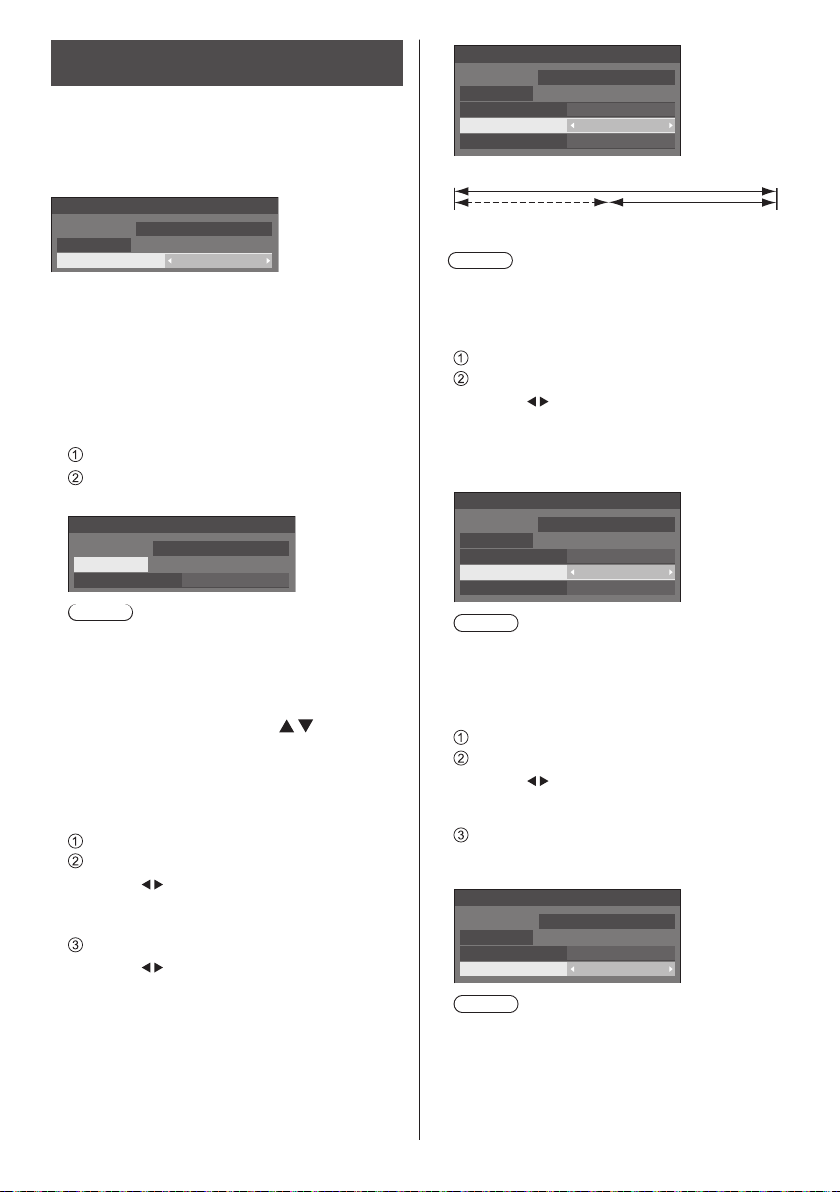
Screensaver (For preventing image retention)
Do not display a still picture, especially in 4:3 mode, for
any length of time.
If the display must remain on, a Screensaver should be
used.
[Screensaver] - submenu screen
Screensaver
10:00
Start
Mode Off
2017/01/01
SUNDAY
■ Screensaver settings
Screensaver operation
When the Screensaver is operating, the following 5
patterns are displayed full screen for 5 seconds each,
and it will be repeated.
Black → Dark grey → Grey → Light grey → White →
Light grey → Grey → Dark grey
To start Screensaver now
Select [On] in [Mode].
Select [Start] and press <ENTER>.
●
The Screensaver will be activated.
Screensaver
10:00
SUNDAY
Start
Mode On
Note
●
If the following buttons are pressed while the
screen saver is operating, the screen saver is
cancelled.
Remote control: <RETURN>
Main unit: <MENU (Unit)> <INPUT (Unit)>
●
When the display is turned off, the Screensaver will
be deactivated.
To set interval of Screensaver
Select [Interval] in [Mode].
Set [Periodic time].
●
Press
●
In [ENGLISH(US)] OSD language, [Periodic
time] is displayed as [SHOW DURATION].
Set [Operating time].
●
Press
Keep pressing down to change the time by 15
minutes.
●
In [ENGLISH(US)] OSD language, [Operating
time] is displayed as [SAVER DURATION].
2017/01/01
<+ (Unit)> <- (Unit)>
<ENTER (Unit)>
to change the time by 15 minutes.
once to change the time by 1 minute.
Screensaver
Start
Mode Interval
Periodic time
Operating time
2017/01/01 10:00
SUNDAY
0:00
0:00
Periodic time
Deactivated. Operating time
Note
●
It is not possible to set the duration of [Operating
time] longer than that of [Periodic time].
To set start and finish time of Screensaver
Select [Time designation] in [Mode].
Set [Start time] and [Finish time].
●
once to change the time by 1 minute.
Press
Keep pressing down to change the time by 15
minutes.
●
In [ENGLISH(US)] OSD language, [Time
designation] is displayed as [TIME OF DAY].
Screensaver
10:00
Start
Mode Time designation
Start time
Finish time
2017/01/01
SUNDAY
0:00
0:00
Note
●
When the current time is displayed as [- -], set
[Date and time] before setting [Start time] and
[Finish time]. (see page 57)
To turn the power off after Screensaver
Select [Standby after SCR saver] in [Mode].
Set [Screensaver duration].
●
once to change the time by 1 minute.
Press
Keep pressing down to change the time by 15
minutes.
Select [Start] and press <ENTER>.
●
Screensaver will be activated and the power will
be turned off (standby) at the time set.
Screensaver
10:00
Start
Mode
Screensaver duration 0:00
2017/01/01
SUNDAY
Standby after SCR saver
Note
●
[Screensaver duration] can be set from 0:00 to
23:59.
When this is set to [0:00], [Standby after SCR
saver] will not be activated.
50
English
Page 51
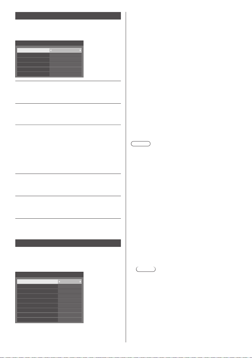
Input label
This function can change the label of the Input signal to
be displayed.
[Input label] - submenu screen
Input label
HDMI1
HDMI2
DIGITAL LINK DIGITAL LINK
DVI-D
PC
VIDEO
HDMI1
HDMI2
DVI-D
PC
VIDEO
[HDMI1] [HDMI1] / [DVD1] / [DVD2] /
[DVD3] / [Blu-ray1] / [Blu-ray2] /
[Blu-ray3] / [CATV] / [VCR] /
[STB] / (Skip)
[HDMI2] [HDMI2] / [DVD1] / [DVD2] /
[DVD3] / [Blu-ray1] / [Blu-ray2] /
[Blu-ray3] / [CATV] / [VCR] /
[STB] / (Skip)
[DIGITAL LINK] [DIGITAL LINK] / [DVD1] /
[DVD2] / [DVD3] / [Blu-ray1] /
[Blu-ray2] / [Blu-ray3] / [CATV] /
[VCR] / [STB] / (Skip)
[DVI-D] [DVI-D] / [DVD1] / [DVD2] /
[DVD3] / [Blu-ray1] / [Blu-ray2] /
[Blu-ray3] / [CATV] / [VCR] /
[STB] / (Skip)
[PC] [PC] / [DVD1] / [DVD2] /
[DVD3] / [Blu-ray1] / [Blu-ray2] /
[Blu-ray3] / [CATV] / [VCR] /
[STB] / (Skip)
[VIDEO] [VIDEO] / [DVD1] / [DVD2] /
[DVD3] / [Blu-ray1] / [Blu-ray2] /
[Blu-ray3] / [CATV] / [VCR] /
[STB] / (Skip)
(Skip): When <INPUT> is pressed, the input will be
skipped.
Power management settings
Set each item to reduce power consumption.
This function works only for the input terminal that is
currently selected.
[Power management settings] - submenu screen
Power management settings
Power management mode
No signal power off
HDMI1 power management
HDMI2 power management O ff
DIGITAL LINK power management
DVI-D power management
PC power management
Power save
Extended standby mode
Custom
Disable
Off
Off
Off
Off
Off
Off
■ [Power management mode]: [On]
The following fixed values are set to the menu of
power consumption reduction. Individual setting is not
available.
[No signal power off]: [Enable]
[HDMI1 power management]: [On]
[HDMI2 power management]: [On]
[DIGITAL LINK power management]: [On]
[DVI-D power management]: [On]
[PC power management]: [On]
[Power save]: [On]
■ [Power management mode]: [Custom]
The menu of the power consumption reduction is
individually set. This setting is enabled when [Power
management mode] is set to [Custom].
[No signal power off]
When this is set to [Enable], the power supply of the
unit goes off automatically (standby) when there is no
operation or sync signal for about 10 minutes.
Note
●
When set to the USB input, the unit determines no
signal is present if the USB memory is not connected
to the USB terminal, or the connected USB memory
does not contain any playable file.
●
This function operates regardless of the [On] / [Off]
settings of [No signal image settings].
●
This function may not operate depending on the video
output devices.
[HDMI1 power management]
When this function is set to [On], it operates under
the following conditions to turn the power on or off
automatically.
When no pictures (sync signal) are detected for
60 seconds or so at HDMI1 input:
Power is turned off (standby); the power indicator
lights up orange.
When pictures (sync signal) are subsequently
detected at HDMI1 input:
Power is turned on; the power indicator lights up
green.
Note
●
This function may not operate depending on the
video output devices.
English
51
Page 52
[HDMI2 power management]
When this function is set to [On], it operates under
the following conditions to turn the power on or off
automatically.
When no pictures (sync signal) are detected for
60 seconds or so at HDMI2 input:
Power is turned off (standby); the power indicator
lights up orange.
When pictures (sync signal) are subsequently
detected at HDMI2 input:
Power is turned on; the power indicator lights up
green.
Note
●
This function may not operate depending on the
video output devices.
[DIGITAL LINK power management]
When this function is set to [On], it operates under
the following conditions to turn the power on or off
automatically.
When no pictures (sync signal) are detected for
60 seconds or so at DIGITAL LINK input:
Power is turned off (standby); the power indicator
lights up orange.
When pictures (sync signal) are subsequently
detected at DIGITAL LINK input:
Power is turned on; the power indicator lights up
green.
Note
●
This function may not operate depending on the
video output devices.
[DVI-D power management]
When this function is set to [On], it operates under
the following conditions to turn the power on or off
automatically.
When no pictures (sync signal) are detected for
60 seconds or so at DVI-D input:
Power is turned off (standby); the power indicator
lights up orange.
When pictures (sync signal) are subsequently
detected at DVI-D input:
Power is turned on; the power indicator lights up
green.
Note
●
This function may not operate depending on the video
output devices.
[PC power management] (DPMS function)
When this function is set to [On], it operates under
the following conditions to turn the power on or off
automatically.
When no pictures (HD/VD sync signals) are
detected for 60 seconds or so at PC input:
Power is turned off (standby); the power indicator
lights up orange.
When pictures (HD/VD sync signals) are
subsequently detected at PC input:
Power is turned on; the power indicator lights up
green.
Note
●
This function is effective when [Sync] in [Signal] is set
to [Auto] or [HV sync] and [Component/RGB-in select]
are set to [RGB]. (see page 47)
●
This function may not operate depending on the video
output devices.
[Power save]
This function adjusts the brightness of the backlight to
reduce power consumption.
[Off]:
This function does not operate.
[On]:
Backlight brightness is reduced.
[Extended standby mode]
Sets the operation in standby mode by the “Power
management” function for the input terminal for which
the “Power management” function is set to [On].
[On]:
If a video signal (synchronized signal) is detected
at any of the input terminals for which the “Power
management” function is set to [On], the power
is turned “ON”, and the input is switched to the
detected input.
[Off]:
If a video signal (synchronized signal) is detected
at the input terminal with which the standby mode
is entered, the power is turned “ON” with the input.
Note
●
If [Input search] is set to items other than [Off], the
[Input search] function is prioritised. (The “Power
management” function does not operate for each
terminal.) (For details of [Input search] function, see
page 68.)
●
If [Failover/Failback] is set to items other than [Off],
the [Failover/Failback] function is prioritised. (The
“Power management” function does not operate for
each terminal.) (For details of [Failover/Failback]
function, see page 69.)
52
English
Page 53
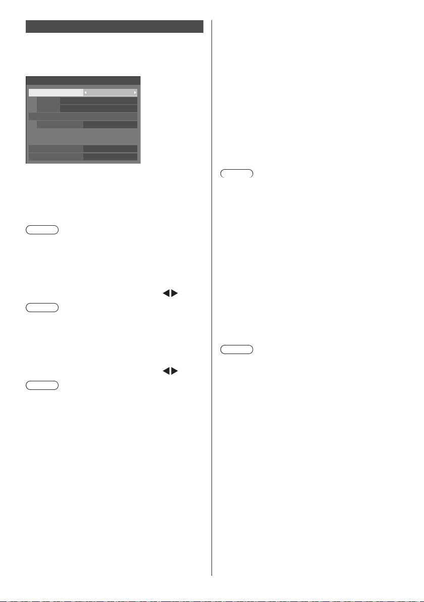
HDMI-CEC settings
Set for HDMI-CEC function.
For details of HDMI-CEC function, refer to “About
HDMI-CEC function”. (see page 112 )
[HDMI-CEC settings] - submenu screen
HDMI-CEC settings
HDMI-CEC control Enable
HDMI1
HDMI2
HDMI-CEC operation
MENU code
Link function
Display→Device
Device→Display
----
----
1
Disable
Disable
■ [HDMI-CEC control]
Enables/Disables the HDMI-CEC function.
[Disable]: Disables HDMI-CEC control.
[Enable]: Enables HDMI-CEC control.
Note
●
Set to [Enable] to operate HDMI-CEC compatible
device with remote control of the unit.
■ [HDMI1]
Displays the device to operate when HDMI-CEC
compatible device is connected to HDMI 1 terminal.
The control subject can be changed with
Note
●
When there is no connected device, [----] will be
displayed.
.
■ [HDMI2]
Displays the device to operate when HDMI-CEC
compatible device is connected to HDMI 2 terminal.
The control subject can be changed with
Note
●
When there is no connected device, [----] will be
displayed.
.
■ [HDMI-CEC operation]
Displays the operation screen of the HDMI-CEC
compatible device.
Press <RETURN> to hide the operation screen.
■ [MENU code]
Changes the code to assign for the [MENU] operation
on the HDMI-CEC operation screen.
Adjust the code to that of the connected HDMI-CEC
compatible device.
■ [Display → Device]
Enables/Disables this unit to perform interlocking
control of the HDMI-CEC compatible device.
[Disable]:
Disables this unit to perform interlocking control of the
HDMI-CEC compatible device.
Even if the power status of this unit changes, the
power status of the device will not be affected.
[Power off]:
Turning this unit off (standby) turns off (standby) all
the devices connected to the HDMI 1 and HDMI 2
terminals. The power-on operation is not interlocked.
[Power on / off]:
The device turns on/off (standby) in conjunction with
the power-on/off (standby) operation of this unit.
Note
●
For details of operation, refer to “About HDMI-CEC
function”. (see page 112 )
■ [Device → Display]
Enables/Disables the HDMI-CEC compatible device
to perform interlocking control of this unit.
[Disable]:
Disables the HDMI-CEC compatible device to perform
interlocking control of this unit.
Even if the power status of the device changes, the
power status of this unit will not be affected.
[Power on]:
Turning on the device turns on this unit, and the input
(HDMI1/HDMI2) is switched to that of the device.
[Power on / off]:
The power status of this unit interlocks with the
power-on/off operation of the device.
Note
●
For details of operation, refer to “About HDMI-CEC
function”. (see page 112 )
●
Input will not be switched when [Options] - [Input lock]
is set.
English
53
Page 54
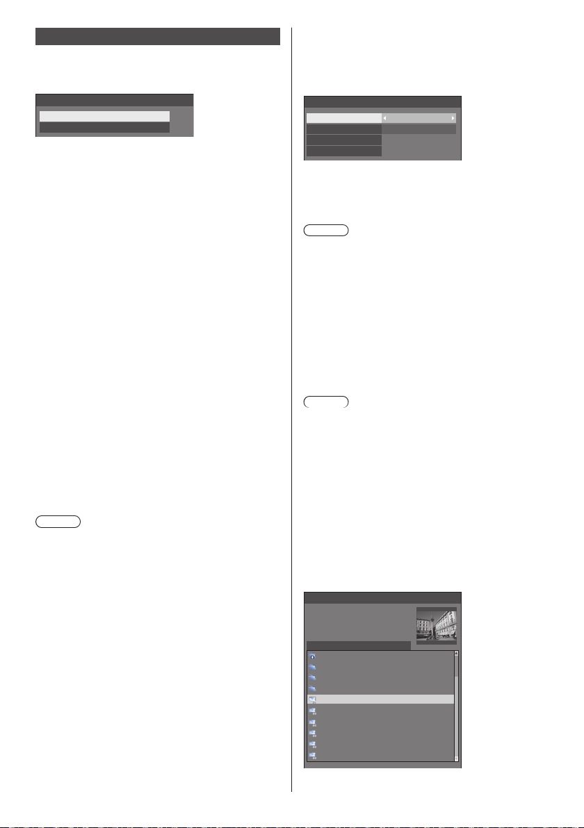
Image settings
Sets the image displayed on the screen when the
power is turned on or no signal is input.
[Image settings] - submenu screen
Image settings
Startup image settings
No signal image settings
[Startup image settings]:
Sets the image displayed when the power is turned on.
[No signal image settings]:
Sets the image displayed when there is no signal at the
selected input terminal.
Conditions of the image that can be set in [Read
user image]
●
Image size: 1 920 x 1 080 only
●
jpg files / bmp files (except for the ones that cannot
be played back with USB media player (see page 96))
●
jpg files (Applies only to a no-signal image of
3.5 MB or less in file size.)
File and folder names are displayed on the file list with
conditions as below.
‒Ifafileorfolderisplaceddirectlyundertheroot
directory of the USB device.
●
Up to 246 characters of file name (including the
extension) are properly displayed.
Note that the file list may disappear due to the display
time of the on-screen menu before the entire display
of file names completely appears.
●
Up to 244 characters of folder name are properly
displayed.
If the folder is placed hierarchically, the number of
•
characters displayed decreases by the number of
characters for the file path (folder information).
‒OnlythefileswithfilenamesdescribedwithASCII
characters excluding control code are displayed.
Note
●
[Picture] cannot be adjusted when setting the startup
image.
●
Only [Backlight] and [Colour temperature] can be
adjusted when setting the no-signal image.
●
Images displayed for the startup image and no-signal
image may slightly differ from images confirmed on
the computer.
■ [Startup image settings] /
[No signal image settings]
Operate [No signal image settings] in the same way
as [Startup image settings].
[Startup image settings] - submenu screen
Startup image settings
Display setting
Image select
Read user image
Clear user image
[Display setting]
Sets the image display when the power is turned on.
[Off]: The function does not operate.
[On]: Enables the function.
Note
●
When no-signal image is displayed, the screen
position moves at certain intervals and images are
displayed to alleviate burn-in on the LCD panel.
●
Shifts the display position regardless of the setting of
[Wobbling] (see page 55).
●
When this function is operating, part of the screen
may appear to be missing.
[Image select]
Select the image to display.
[Default image]: Panasonic logo (blue background)
[User image]: Image registered by the user
Note
●
Only when [Default image] is displayed, the logo
automatically rotates when displayed, according
to the [Display orientation] (see page 66) setting
([Landscape] / [Portrait]).
●
When [User image] is selected, the image does not
rotate according to the [Display orientation] setting.
Prepare an image of 1 920 x 1 080 aspect ratio
compatible with the installation direction.
●
[Default image] of [No signal image settings] is the
Panasonic logo (black background).
[Read user image]
Register the image read from a USB memory device.
[Read user image] - submenu screen
Read user image
Select a no signal image.
usb/picture/
..
0_folder_sample
g_sample
z_sample
1sample.jpg
2sample.jpg
3sample.jpg
a_sample.jpg
j_sample.jpg
v_sample.jpg
On
User image
54
English
Page 55
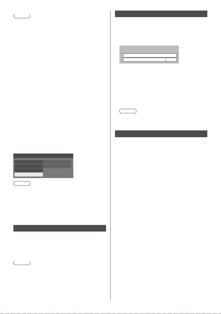
Note
●
Set the input to something other than [USB] or
[MEMORY VIEWER], and read the image.
●
One user image can be registered for [Startup image
settings] and [No signal image settings] respectively.
●
Do not turn the power off while reading the user
image.
●
The selected image is previewed on the [Read user
image] submenu screen.
●
When USB memory device is not connected to the
USB terminal, [Read user image] is greyed out and
cannot be selected.
●
If starting to read the image while creating the
preview image, an access error will occur, and the
image may not be recognized as a image file.
Confirm the preview image display, and then start
reading process.
●
The displayed file names are restricted as follows.
Applicable extension: jpg, jpe, jpeg or bmp
•
The file name is not “.jpg”, “.jpe”, “.jpeg”, or “.bmp”
•
which start with dot (.).
●
Depending on the OS setting, folders or files in the
USB memory invisible on your computer may be
displayed on this unit.
[Clear user image]
Clears the image registered in [Read user image].
[Startup image settings] - submenu screen
Startup image settings
Display setting
Image select
Read user image
Clear user image
On
User image
Note
●
When there is no [User image] that have been read,
[Clear user image] is greyed out and cannot be
selected.
●
When [Image select] is set to [User image],
performing [Clear user image] will change the setting
of [Image select] to [Default image].
No activity power off
When this function is set to [Enable], the power is turned
off (standby) automatically when there is no operation of
the Display for 4 hours.
Starting from 3 minutes before the turn off, the
remaining time will be displayed.
Press any key to abort.
No activity power off
3 min
When the power is turned off due to this function, a
message [Last turn off due to ’No activity power off’.]
is displayed next time the power is turned on.
When the image set in [No signal image settings] (see
page 54) is displayed, remaining time is not displayed
even when the power is going to be turned off in 3
minutes. Instead, the image is displayed until the
power is turned off.
Note
●
While the screensaver is running, this function is
disabled.
OSD language
Select your preferred language.
Selectable languages
English(UK)
Deutsch
Français
Italiano
Español
ENGLISH(US)
中文
日本語
Русский : Russian
: Chinese
: Japanese
Wobbling
Automatically shifts the display image (therefore
unnoticeable to the eye) to prevent image retention of
sharper contour of image.
Setting this to [On] moves the screen position at certain
intervals and displays the images.
Note
●
If [Multi display setting] is set to [On], this function
does not operate. (see page 56)
●
When this function is operating, part of the screen
may appear to be missing.
English
55
Page 56
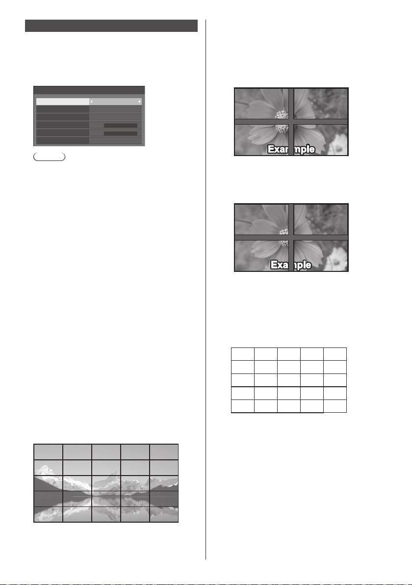
Multi display settings
....
1 to 10 displays can be aligned in horizontal direction
and vertical direction respectively, and those displays
are regarded as one group. The enlarged image is
shown on the combined display.
[Multi display settings]- submenu screen
Multi display settings
Multi display setting
Horizontal scale
Vertical scale
Bezel H adjustment
Bezel V adjustment
Location
Note
●
The settings are memorised separately for each
input terminal.
●
When the multi display is set to [Off], adjust to the
same angle of view for [Position] (see page 38).
Then, set the multi display to [On]. Again, make
fine adjustment of the angle of view for [Position].
●
The [Position] menu can be adjusted in the multi
display status.
●
For USB input, [Horizontal scale] and [Vertical
scale] can be set only with the following
combinations.
1 × 2, 1 × 3, 1 × 4, 2 × 1, 2 × 2, 3 × 1, 4 × 1
Off
2
2
0
0
A1
■ [Multi display setting]
[Off]:
The display is not divided when enlarged.
[On]:
The display is divided when enlarged.
When [On] is set, the display aspect is [16:9].
■ [Horizontal scale]
Set the horizontal scale in the multi display.
1 to 10
■ [Vertical scale]
Set the vertical scale in the multi display.
1 to 10
Example:
[Horizontal scale] [5] and [Vertical scale] [5] is set in
the multi display
■ [Bezel H adjustment] / [Bezel V adjustment]
Adjust the area of image hidden in the joint
horizontally and vertically respectively.
0 ‒ 100
Display example
Setting value: 0
Displays the entire image including the joint area.
(Suitable when displaying character information
on PC.)
Setting value: 100
Does not display the image of the joint area.
(Suitable when displaying motion pictures.)
■ [Location]
Assign the multi display position.
Example:
[Horizontal scale] [10], [Vertical scale] [10]
A1 A2
B1 B2
.... ....
I1 I2 I9
J1 J2 J9
Select from A1 to J10.
●
The displayed content for setting changes
according to the settings for the [Horizontal scale]
and [Vertical scale].
●
By setting [Multi display setting] to [Off], it is
possible to check the location on the screen while
the setting menu is displayed.
....
....
....
....
A9
B9
....
A10
B10
....
I10
J10
56
English
Page 57
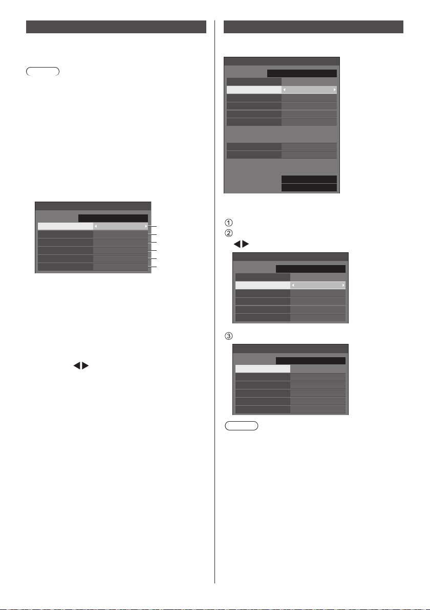
Set up timer
Sets the program to turn the power on with the specified
time and video input, or to turn the power off at the
specified time. Up to 20 programmes can be set.
Note
●
When the current time is displayed as [- -], set [Date
and time] before setting [Set up timer]. (see page 57)
●
When multiple programs are set at the same time,
the program with the smallest program number is
enabled.
●
If [Power mode] is set to [Power on], executing the
program at power-on will switch to the input set for
[Input].
[Set up timer] - submenu screen
Setting Example
Program 1, Every Monday, 12:00,
Power On, Input: HDMI1
Set up timer
10:00
SUNDAY
Program
Timer function
Day
Power mode
Time
Input
Set the program number.
1
To execute the program, set to [On].
2
The program is disabled when [Off] is set.
Set the day.
3
The program is executed every day when
[Everyday] is set.
Set the power On/Off.
4
Set the time.
5
Pressing
Pressing continuously changes time by 15
minutes.
Set the input.
6
2017/01/01
1
On
MONDAY
Power on
12:00
HDMI1
1
2
3
4
5
6
once changes time 1 minute.
Date and time
Set date and time. ([- -] shows no programme is set.)
[Date and time] - submenu screen
Date and time
2017/01/01
Set
Year 2017
Month
Day
Hour
Minute
Synchronize display setting
Synchronize display Off
Parent or child setting Child
NTP status
NTP synchronization Off
Time zone (GMT + 00:00)
SUNDAY
1
1
10
0
10:00
■ Set date and time
Select [Year / Month / Day / Hour / Minute].
Set the selected item.
Date and time
2017/01/01
Set
Year 2017
Month
Day
Hour
Minute
Select [Set] and press <ENTER>.
Date and time
2017/02/05
Set
Year 2017
Month
Day
Hour
Minute
Note
●
If the present date and time are not set, the time
settings for [Set up timer], [Screensaver], etc. cannot
be made.
●
The present date and time setting is reset in the
following case.
When the main unit is left unattended for 7 days or
longer after the main unit is turned off with the <Main
Power On / Off button>, the power plug is removed,
or power failure has occurred, etc.
●
Date and time cannot be set when [Year / Month /
Day / Hour / Minute] are set to [- -].
●
The upper limit of date and time that can be set is,
Year 2035, Month 12, Day 31, Hour 23 and Minute
59.
SUNDAY
1
1
10
0
SUNDAY
2
5
18
0
10:00
18:00
99:992015/01/01
English
57
Page 58
■ [Synchronize display setting]
Synchronizes the time of all the displays connected on
the network.
Note
●
This function does not operate if the displays to
synchronize the time are not connected via a LAN.
●
This function operates only when the devices
connected via a LAN are connected with different IP
addresses.
●
The time synchronization operates only in power-on
state or in schedule standby state.
●
Normal operation is achieved only when the display
synchronization function is enabled among the units.
If other devices are connected on the same network,
operation may not be normal.
[Synchronize display]:
Enables/Disables display synchronization function.
[Parent or child setting]:
Set this unit to [Parent] or [Child] for display
synchronization.
Operates when [Synchronize display] is [On].
[Parent]:
Set the time as a source of synchronization.
[Child]:
Synchronizes with the time of the parent.
Note
●
When [Synchronize display] is [On], and [Parent or
child setting] is [Child], date and time cannot be set.
●
When [Synchronize display] is [On], and [Parent or
child setting] is [Child], [NTP synchronization] offoperation is performed.
●
If two or more displays with [Parent] set are present
on one network, display synchronization does not
operate properly.
●
Time is not synchronized if no displays with [Parent]
set is present on one network.
●
Time is not synchronized if the time is not set for the
display with [Parent] set on the network.
●
Depending on the network environment,
synchronization may be largely lost.
●
Synchronization is not possible if a router is placed
between displays.
●
Synchronization is not possible via a wireless LAN.
■ [NTP status]
Displays the current [NTP synchronization] and [Time
zone] (see page 90) settings.
Note
●
When [NTP synchronization] is set to [On], and if
[Synchronize display] and [Parent or child setting]
are set to [On] and [Child] respectively, [NTP
synchronization] shows [--], and the off-operation is
performed.
●
When [NTP synchronization] is [On], date and time
cannot be set.
●
The settings for [NTP synchronization] and [Time
zone] cannot be changed with this menu. Change
the settings with WEB browser. (see page 90)
●
[NTP synchronization] operates only in power-on
state or in schedule standby state.
58
English
Page 59
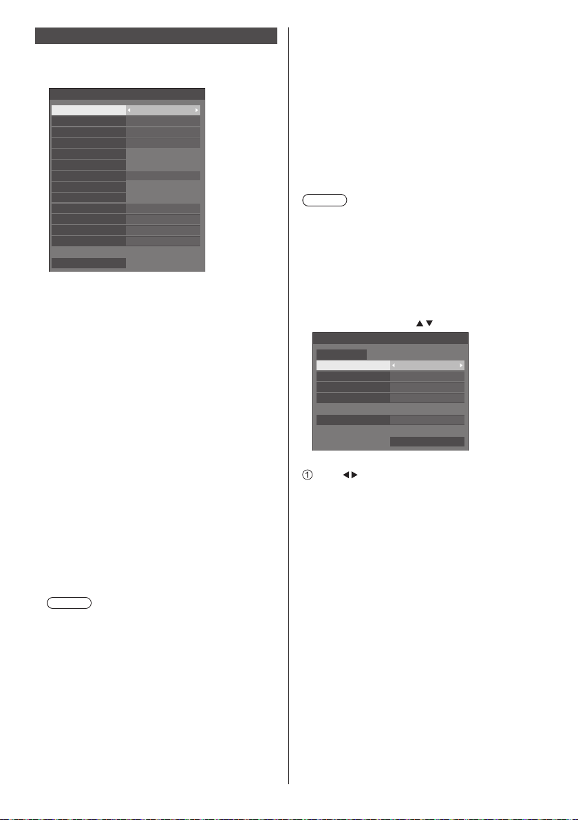
Network settings
Set when networking with a computer.
[Network settings] submenu will be displayed.
Network settings
Serial control
Network control
Display name
LAN setup
Network status
DIGITAL LINK mode
DIGITAL LINK status
DIGITAL LINK menu
AMX D. D.
Crestron Connected™
Extron XTP
USB memory network settings
Reset
SERIAL IN
Off
OffAuto display name
SF2-000
Auto
Off
Off
Off
Permit
■ [Serial control]
(TH-65SF2E only)
Selects the RS232-C control terminal.
[SERIAL IN]:
Controls using the SERIAL IN terminal of the
display.
[DIGITAL LINK]:
Controls via the optional device that supports
DIGITAL LINK output (ET-YFB100G, ETYFB200G) and the DIGITAL LINK / LAN terminal.
■ [Network control]
Set when controlling with the unit’s LAN terminal.
[On]:
Controls via LAN using the LAN terminal of the
Display. The power indicator lights orange when
the power is turned off with the remote control
(standby).
[Off]:
Invalidates control with LAN terminal.
(In this case, the power consumption of Standby
condition (when the power is turned off with the
remote control) will be slightly reduced.)
Note
●
When using the LAN control function which is
described in “Using Network Function” (see page
77‒94), set this function to [On].
●
Even if the setting is set to [Off], the Web browser
control screens that do not control this unit
(display information [Status], detailed settings
[Detailed set up] and password change [Change
password]) operate.
■ [Auto display name]
Sets whether to change the display name
automatically.
[On]:
Changes the display name automatically in
accordance with the set point of the display ID.
[Off]:
The display name is not changed automatically.
■ [Display name]
The name of the Display that is shown on the network
can be changed.
Note
●
The name can be changed only when [Auto display
name] is set to [Off].
●
Display ID is not reset to default with [Network
settings] - [Reset].
■ [LAN setup]
Detailed network settings for the LAN established via
the LAN terminal of the Display can be configured.
Select [LAN setup] with
LAN setup
Save
DHCP Off
IP address
Subnet mask
Gateway
Port
MAC address
[DHCP], [IP address], [Subnet mask], [Gateway]
Press to set [On] / [Off] of [DHCP].
When [Off] is selected, IP address and other settings
can be set manually.
[DHCP]:
(DHCP client function)
[On]:
Obtains an IP address automatically when a
DHCP server exists in the network the Display is
going to be connected.
[Off]:
When a DHCP server does not exist in the
network the Display is going to be connected,
set [IP address], [Subnet mask] and [Gateway]
manually.
[IP address]:
(IP address display and setting)
Enter an IP address when DHCP server is not
used.
[Subnet mask]:
(Subnet mask display and setting)
Enter a Subnet mask when DHCP server is not
used.
and press <ENTER>.
192.168. 0. 8
255.255.255. 0
192.168. 0. 1
1024
12:34:56:78:9A:BC
English
59
Page 60
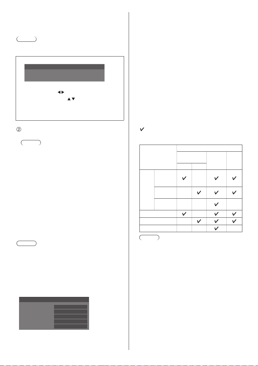
[Gateway]:
(Gateway address display and setting)
Enter a gateway address when DHCP server is not
used.
Note
●
When [DHCP] is set to [On], the IP address, etc. will
be displayed in grey.
Entering numbers
IP address
192.168.000.008
I
1. Select the address and press <ENTER>.
2. Select digits with
3. Change numbers with
.
.
4. Press <ENTER>.
You can cancel the change by pressing
<RETURN>.
Select [Save] and press <ENTER>.
Save the current network Setup.
Note
●
To use a DHCP server, make sure the DHCP
server is started.
●
Contact your network administrator for details on
[IP address], [Subnet mask] and [Gateway].
●
Shipping condition
[DHCP]: Off
[IP address]: 192.168.0.8
[Subnet mask]: 255.255.255.0
[Gateway]: 192.168.0.1
[Port]
Set the port number used for command control.
Select [Port] and press <ENTER> to set the number.
●
Theavailablesettingrangeis1024‒65535.
●
Entering numbers (see page 60)
Note
●
When the PJLink protocol is used, the port setting is
not necessary.
[MAC address]
Displays the MAC address of this unit.
■ [Network status]
Checks the current Network settings status.
Network status
DHCP
IP address
Subnet mask
Gateway
MAC address
Off
192. 168. 0. 8
255. 255. 255. 0
192. 168. 0. 1
12:34:56:78:9A:BC
■ [DIGITAL LINK mode]
(TH-65SF2E only)
Switches communication method of DIGITAL LINK
terminal.
[Auto]:
Communication method is selected automatically.
HDMI, LAN, serial communication are possible.
Ethernet connection is possible.
[DIGITAL LINK]:
HDMI, LAN, serial communication are possible via a
twisted pair cable transmitter.
[Ethernet]:
LAN communication is possible via the LAN terminal
of the display.
[Long reach]:
Communication method is fixed to Long reach.
Modes allowing communication
Valid
:
― : Invalid
Communication validity
Settings
For
DIGITAL
LINK
For Long
Auto
reach
For
Ethernet
DIGITAL LINK
Long reach ―
Ethernet ― ― ―
Note
●
When connected with the [Long reach]
communication method, the maximum
transmission distance is 150 m. In this case, this
unit can receive the signals of up to 1080/60p
(148.5 MHz).
●
If the communication method of the twisted
pair cable transmitter is set to [Long reach], set
[DIGITAL LINK mode] to [Auto]. Then, connection
is enabled with the [Long reach] communication
method.
When connecting with the separately sold DIGITAL
LINK Switcher (ET-YFB200G) with the [Long
reach] communication method, set [DIGITAL LINK
mode] to [Long reach].
●
Even if [DIGITAL LINK mode] is set to [Long
reach], when the twisted pair cable transmitter
does not support the communication method of
[Long reach], it will not be connected properly.
Picture
transmission
Ethernet
100 m 150 m
―
―
― ― ―
―
RS-
232C
60
English
Page 61
■ DIGITAL LINK status
(TH-65SF2E only)
Display the DIGITAL LINK connection environment.
Select [DIGITAL LINK status] with
<ENTER>.
DIGITAL LINK status
LINK status
HDMI status
Signal quality
Min
Max
No link
No HDMI
-XX dB
-YY dB
[LINK status]:
1 of the followings will be displayed.
[No link]:
No LAN connection, etc.
[DIGITAL LINK]:
Connected to the DIGITAL LINK device by LAN.
[Long reach]:
Communication method is set to [Long reach] and
is connected to the DIGITAL LINK device by LAN.
[Ethernet]:
The PC is connected to the DIGITAL LINK / LAN
terminal of this product and is LAN connected.
[HDMI status]:
Displays the connection status of the HDMI format.
1 of the followings will be displayed.
[No HDMI]:
DIGITAL LINK not connected
[HDMI on]:
DIGITAL LINK connected
[HDCP on]:
HDCP supported on DIGITAL LINK
[Signal quality]:
It is the quantified minimum and maximum numbers
of errors that have occurred. The display colours are
red, yellow, or green, depending on the number.
Signal quality
Display
Colours
-12dB or below Green Good
-11 to -8dB Yellow Bad
-7dB or above Red Terrible
●
The number is represented by yellow or red if
the LAN cable is disconnected or the cable is not
shielded.
●
This signal quality shows figures between the
twisted pair cable transmitter that is connected and
the display.
and press
Reception
Status
■ DIGITAL LINK menu
(TH-65SF2E only)
Displays the setting menu of Digital Interface Box.
Select [DIGITAL LINK menu] with
<ENTER>.
Note
●
This function can only be selected when the
Panasonic device that supports DIGITAL LINK output
(ET-YFB100G, ET-YFB200G) is connected to a
DIGITAL LINK / LAN terminal and its power is on.
●
For details, refer to the manuals of the devices that
support DIGITAL LINK output.
and press
■ [AMX D. D.]
Set whether to allow the Display to be detected by AMX
Device Discovery.
[On]:
Enables detection by AMX Device Discovery.
[Off]:
Disables detection by AMX Device Discovery.
●
For more details, visit the following web site.
http://www.amx.com/
■ [Crestron Connected™]
When this function is set to [On], the Display can
be monitored or controlled via the network using
equipment and application software of Crestron
Electronics, Inc.
This Display supports the following application software
from Crestron Electronics, Inc.
RoomView® Express
•
Fusion RV
•
RoomView® Server Edition
•
®
[Crestron Connected™] is a function to connect to
a system developed by Crestron Electronics, Inc.
which manages and controls multiple system devices
connected to the network.
●
For details of “Crestron Connected™”, refer to the
Crestron Electronics, Inc. web site (Provided only in
English).
http://www.crestron.com/
®
For the download of “RoomView
Express”, refer to
the Crestron Electronics, Inc. web site (Provided only
in English).
http://www.crestron.com/getroomview
■ [Extron XTP]
(TH-65SF2E only)
Set to [On] when connecting XTP Transmitter made by
Extron to DIGITAL LINK terminal.
●
For more details on Extron, visit the following web
site.
http://www.extron.com
English
61
Page 62
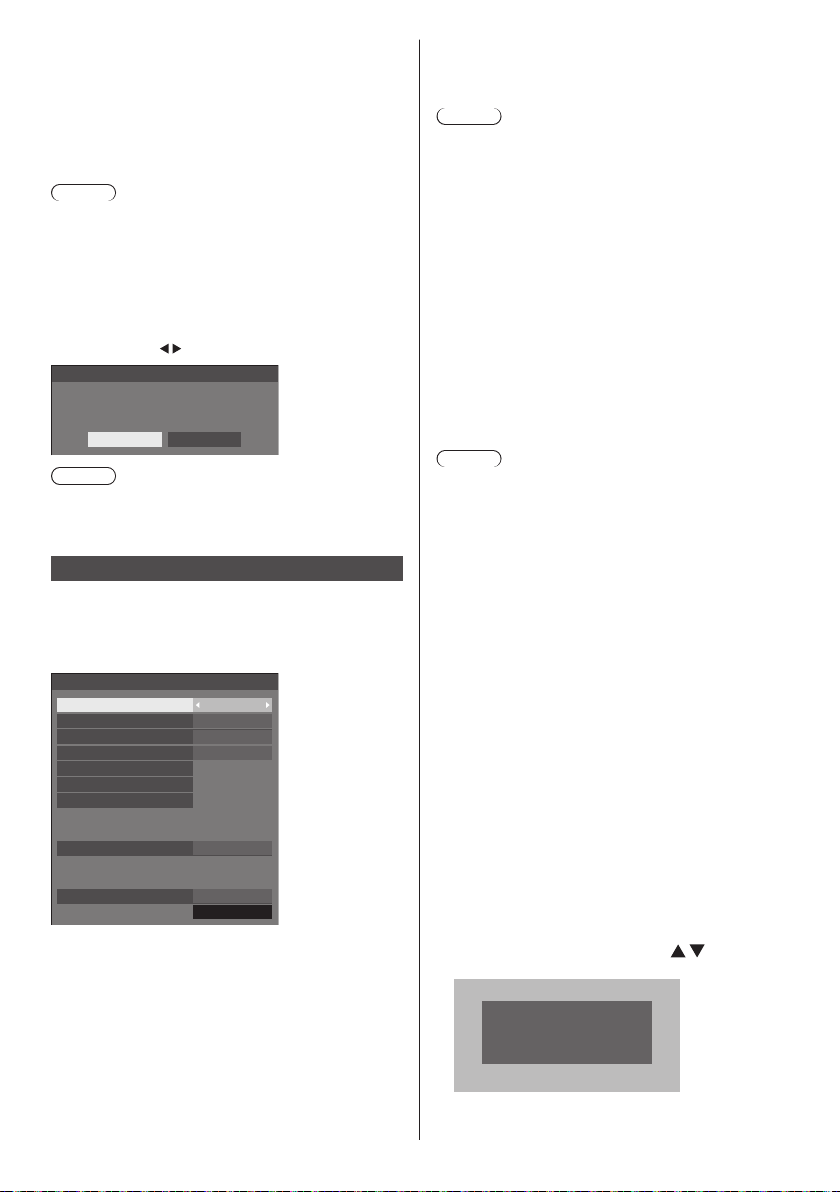
■ [USB memory network settings]
Sets whether to permit the network setting using the
USB memory device. (see page 118 )
[Permit]:
Permits USB memory network settings.
[Prohibit]:
Prohibits USB memory network settings.
Note
●
This function is set to [Permit] as factory default.
●
Once the network setting is done with USB memory
device, this function is set to [Prohibit].
■ [Reset]
You can reset the network setting to the factory default
of the Display.
Select [Yes ] with
Network settings
and press <ENTER>.
Reset
Yes No
Note
●
The settings for [NTP synchronization], NTP server
and [Time zone] will be reset to the factory default.
USB media player settings
Set for “USB media player”.
For details of the function, refer to “USB media player”
(see page 95).
[USB media player settings] - submenu screen
USB media player settings
USB media player
Schedule play function Enable
Video playback mode Standard
Resume play On
Playlist edit
Scenario file check
Codec information
No scenario file
Slide show duration
Schedule play function default setting
Play mode Individual play
Current setting Individual play
Enable
10 sec
■ [USB media player]
Set to enable or disable the USB media player
function.
■ [Schedule play function]
Enables/Disables the schedule playback function
using “Content Management Software”.
Note
●
When [Schedule play function] is set to [Enable],
if both the scenario file of the existing “USB media
player” and the schedule file of this function are
present, the [Schedule play function] operation takes
priority.
●
[USB media player] cannot be changed during the
schedule playback mode.
■ [Video playback mode]
Sets the video playback mode.
If image disturbance occurs at the switching timing
of motion picture files during playback in [Standard]
mode, switch to [Adjust] mode.
[Standard]: Plays without a black image at the joint
between video files.
[Adjust]: Plays with a black image (approx. 2
seconds) inserted at the joint between
video files.
Note
●
When using the Multi Media Player, a black screen is
displayed for a certain period of time at the switching
timing of motion picture files regardless of the [Video
playback mode] settings.
●
The display may be disturbed at the switching timing
of files during playback in [Standard] mode.
●
When the schedule playback is proceeding using
“Content Management Software”, [Video playback
mode] can be switched both in single mode and multi
mode.
■ [Resume play]
Set resume play off/on.
■ [Playlist edit]
Creates / Edits the scenario file (scenario.dat).
For details of [Playlist edit], refer to “Playlist edit
function” (see page 102).
■ [Scenario file check]
Execute the contents check of the USB memory
which is connected to the USB terminal. If any error
is detected, the error code and file name will be
displayed.
For details of the error codes, refer to “USB memory
contents check”. (see page 100)
Select [Scenario file check] with
<ENTER>.
Scenario file check
Available
and press
62
English
Page 63
Note
●
When the schedule playback is proceeding using
“Content Management Software”, [Scenario file
check] is disabled.
■ [Codec information]
Displays the codec information of a motion picture/still
picture file being played on the USB media player.
The file is analysed on execution, and the codec
information is displayed after the completion of the
analysis.
Note
●
The file analysis takes time in proportion to the
number of files in the USB memory device.
●
A black screen appears during analysis because
playback is stopped.
●
Incompatible with the schedule play mode.
■ [Slide show duration]
Select the displaying duration for still images.
[10 sec] ‒ [600 sec]
Note
●
When the schedule playback is proceeding using
“Content Management Software, [Slide show
duration] is disabled.
■ Play mode
Specifies the playback mode operating with
[Schedule play function]. To apply this setting to the
schedule playback operation, restart this unit.
Also, if the playback mode is specified for the
schedule data of “Content Management Software”
during the schedule playback, it takes priority.
[Individual play]:
Plays in the individual playback mode.
Content is played only on one display.
[Synchronize play]:
Plays in the synchronized playback mode.
Content is played on multiple displays in
synchronization.
Note approx. 5 seconds of preparation time are
added in switching content to synchronize the
playback timing.
Note
●
The synchronized playback operates properly only
when [Date and time] - [Synchronize display] is set to
[On] and the time is synchronized.
●
[Current setting] shows [Play mode] when the
schedule playback is performed by this unit.
Memory viewer settings
Set for “Memory viewer”.
For details of the function, refer to “Memory viewer” (see
page 107).
[Memory viewer settings] - submenu screen
Memory viewer settings
Memory viewer
Content select
Sort type
Sort order
Play method
Picture duration
Auto display content info
Auto display operation guide
Enable
ThumbnailView
Video
File name
Ascending
None
10 sec
On
On
■ [Memory viewer]
Enables/Disables “Memory viewer”.
■ [View]
Sets the display format of the content in the USB
memory device to the thumbnail display or the list
display.
■ [Content select]
Sets the type of content to display.
[Picture]:
Displays still picture files only.
[Video]:
Displays motion picture files only.
[Music]:
Displays music files only.
[All]:
Displays all the files including still pictures, motion
pictures and music files.
[Picture / Video]:
Displays picture files and video files.
[Picture / Music]:
Displays picture files and music files.
[Video / Music]:
Displays video files and music files.
■ [Sort type]
Sets the order of content in combination with [Sort
order].
■ [Sort order]
Sets the order of content in combination with [Sort
type].
English
63
Page 64
■ [Play method]
Sets the playback method of content.
[None]:
Automatically returns to the content display screen
when the playback of the selected file has finished.
[Single]:
Plays the selected file repeatedly.
[All]:
Plays the content displayed on the content display
screen repeatedly in displayed order.
[Random]:
Plays the content displayed on the content display
screen at random.
[Select]:
Plays the selected files in the sorting order shown on
the content display screen.
[Program]:
Plays the selected file in selected order.
■ [Picture duration]
Sets the display time of still picture files.
10 sec to 600 sec
■ [Auto display content info]
When this is set to [On], the content information
is automatically displayed at the beginning of the
content playback, and the information is automatically
erased after a certain period of time.
■ [Auto display operation guide]
When this is set to [On], the operation guide is
automatically displayed at the beginning of the
content playback, and the information is automatically
erased after a certain period of time.
The playback control (see page 109) is performed
only while the operation guide is being displayed. If it
is not displayed, the unit shows the operation guide
without performing the playback control.
When this is set to [Off], the operation guide is not
displayed at the beginning of the content playback.
The playback control is performed regardless of
Show/Hide of the operation guide.
Note
●
When [Play method] is set to [Single], playback
information and operation guide are automatically
displayed only at the beginning of the first playback
of content.
●
When [Play method] is [Select] or [Program], up to 99
files can be selected.
●
This menu will be greyed out and cannot be set while
content is being played.
Function button settings
Assigns specific functions to the numeric buttons (<1>
to <6>). The buttons can be used as shortcut keys by
assigning frequently used operations.
Switch [Function group] with .
1
[Function button settings] - submenu screen
Function button settings
Function group
Function button 1
Function button 2
Function button 3
Function button 4
Function button 5
Function button 6 MEMORY VIEWER
Function button guide
Select the numeric button with
2
Input
HDMI1
DIGITAL LINK
DVI-D
PC
USB
On
Input
↓
Memory load
↓
Shortcut
and set the function to assign with
.
■ Functions assignable to the numeric
buttons
[Input] (Direct input select)
Input can be selected with single-touch operation.
[HDMI1] / [HDMI2] / [DIGITAL LINK] / [DVI-D] /
[PC] / [VIDEO] / [USB] / [MEMORY VIEWER]
[Memory load]
Memory can be loaded with single-touch operation.
Refer to “Memory load”. (see page 45)
[MEMORY1] to [MEMORY6]
●
[MEMORY1] to [MEMORY6] load functions are
already assigned to <1> to <6> respectively.
These settings cannot be changed.
64
English
Page 65
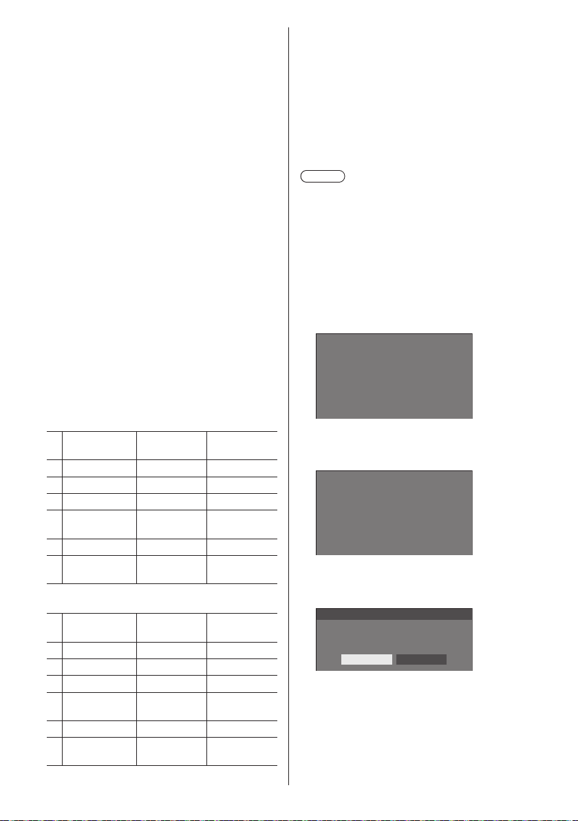
[Shortcut]
[Signal], [Screensaver], [Set up timer], [Power
management settings], [Network settings],
[Multi display settings]
●
Pressing the numeric button displays the menu
screen. Pressing the button again exits the
menu screen.
[AV mute]
●
Pressing the numeric button mutes the audio
and pictures.
To cancel, press any button on the remote
control except the <Standby (ON/OFF) button>.
[Digital zoom]
●
Switches to [Digital zoom] mode by pressing
numeric buttons. (see page 35)
[Display ID / Display name]
●
Pressing the numeric button enlarges [Display
ID] and [Display name].
[HDMI-CEC operation]
●
Press the numeric buttons to display the
operation screen of the HDMI-CEC compatible
device.
[Playlist edit]
●
Pressing the numeric button displays [Playlist
edit] screen. (see page 102)
Shipping condition
The following functions are assigned to the numeric
buttons as factory default.
TH-65SF2E
[Input]
[Memory
load]
[Shortcut]
1 HDMI1 MEMORY1 [Signal]
2 DIGITAL LINK MEMORY2 [Screensaver]
3 DVI-D MEMORY3 [Set up timer]
4 PC MEMORY4
[Network
settings]
5 USB MEMORY5 [AV mute]
MEMORY
6
VIEWER
MEMORY6
[HDMI-CEC
operation]
TH-65SF2U, TH-55SF2U, TH-49SF2U, TH-43SF2U,
TH-55SF2E, TH-49SF2E, TH-43SF2E
[Input]
[Memory
load]
[Shortcut]
1 HDMI1 MEMORY1 [Signal]
2 HDMI2 MEMORY2 [Screensaver]
3 DVI-D MEMORY3 [Set up timer]
4 PC MEMORY4
[Network
settings]
5 USB MEMORY5 [AV mute]
MEMORY
6
VIEWER
MEMORY6
[HDMI-CEC
operation]
■ [Function button guide]
Sets the function display when numeric buttons are
pressed. Set this for each function group.
[On]:
Displays the function list for the numeric buttons.
[Off]:
Does not display the function list. Operation starts
when numeric buttons are pressed.
Note
●
When <FUNCTION> is pressed, [Function button
guide] will be displayed regardless of the [On] / [Off]
settings.
■ To use shortcut (numeric buttons)
Press <FUNCTION> or <1> ‒ <6>.
1
[Function button guide] will be displayed.
[Function button guide]: When [Off] is set, pressing
the numeric button starts operation.
Example: Input
Input
HDMI1
1.
HDMI2
2.
DIGITAL LINK
3.
DVI-D
4.
PC
5.
USB
6.
Press <FUNCTION> to switch function
2
group.
Example: Memory load
Memory load
MEMORY1
1.
MEMORY2
2.
MEMORY3
3.
MEMORY4
4.
MEMORY5
5.
MEMORY6
6.
Press <1> ‒ <6>.
3
The function for the pressed button starts to operate.
Example: When <2> is pressed.
Memory load
Load from “MEMORY2”
Ok Cancel
English
65
Page 66
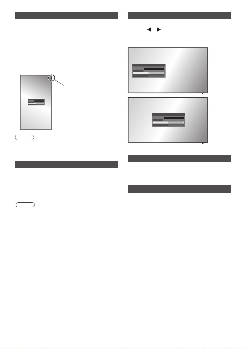
Display orientation
Sets the on-screen display orientation in the portrait
setting.
[Landscape]:
On-screen display angle is for horizontal
installation.
[Portrait]:
The on-screen display rotates clockwise by 90
degrees for easy view in the portrait setting.
Power indicator
18:00
Note
●
In the portrait setting, the power indicator shall come
to the upper side.
Image rotation
Sets the picture rotation in the portrait setting.
[Off]:
Pictures are not rotated.
[180 degrees]:
Pictures are rotated 180 degrees.
Note
●
This function does not operate when [Display
orientation] is [Landscape].
OSD position
Sets the display position of the on-screen menu.
Each time
or is pressed, the display position of the
on-screen menu changes.
Display example:
18:00
Left
18:00
Centre
Menu display duration
Sets the display duration time for the on-screen menu.
[5 sec] ‒ [180 sec]
Menu transparency
Sets the transparency rate of the on-screen display
background.
0 ‒ 100
66
English
Page 67
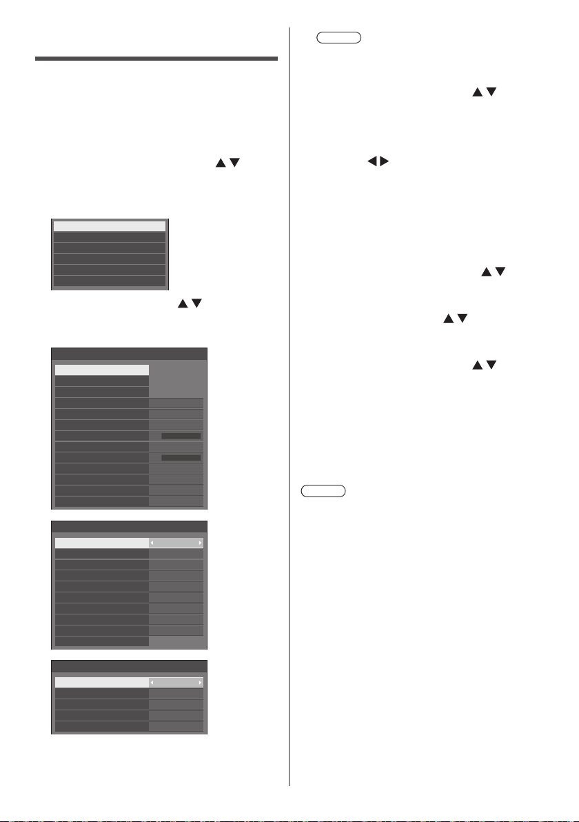
Options Adjustments
This unit offers special functions conveniently used
according to the installation location and application.
■ Remote control
Press <SETUP>.
1
[Setup] menu screen will be displayed.
Select [OSD language] with
2
and press <ENTER> for more than 3
seconds.
Following screen will be displayed.
Options
Display software information
Software licenses
USB data cloning
LAN data cloning
Shipping
Select [Options] with and press
3
<ENTER>.
[Options] menu screen will be displayed.
On
Off
0
0
Off
Off
Off
Off
Enable
Last memory
0
Off
Off
Off
---
1/3
2/3
Options
Input search
Failover/Failback
Audio input select
Onscreen display
Initial input
Initial VOL function Off
Initial VOL level
Maximum VOL function Off
Maximum VOL level
Input lock
Button lock
Controller user level
PC auto setting
Options
Off-timer function
Initial startup
Display ID
Controller ID function
Serial ID function
Serial response(Normal)
Serial response(ID all) Off
Serial daisy chain position
LAN control protocol Protocol 2
Information timing
Note
●
[POWER button lock] function is only for
TH-65SF2U, TH-55SF2U, TH-49SF2U and
TH-43SF2U.
Select the item to set with .
4
For [Input search], [Failover/Failback], [Audio input
select] and [Information timing], the submenu screen
will be displayed when you press <ENTER>.
(see page 68, 74)
Set with .
5
Press <SETUP> to exit from [Options]
6
menu.
■ Unit
Press <MENU (Unit)> for several times
1
and display the [Setup] menu.
Select [OSD language] with ,
2
and then press and hold <ENTER
(Unit)> for more than 5 seconds.
Select [Options] with and press
3
<ENTER (Unit)>.
[Options] menu screen will be displayed.
Select the item to set with .
4
For [Input search], [Failover/Failback], [Audio input
select] and [Information timing], the submenu screen
will be displayed when you press <ENTER>.
(see page 68, 74)
Set with <- (Unit)> or <+ (Unit)>.
5
Press <MENU (Unit)> for several
6
times to exit from [Options] menu.
Note
●
Press <RETURN> to return to the previous menu.
●
The serial number and the software version of this
unit are displayed when [Display software information]
is selected in step 3.
●
The software License is displayed when [Software
licenses] is selected in step 3.
Options
Power on screen delay
Clock display
Power on message(No activity power off)
Power on message(Power management)
POWER button lock Off
3/3
Off
Off
On
On
English
67
Page 68
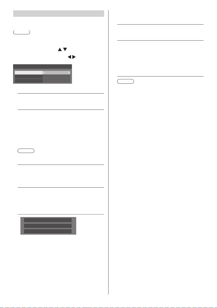
Input search
When a signal is not detected, another input with a
signal is automatically selected.
Note
●
MEMORY VIEWER input is not a subject of the “no
signal” detection. It is excluded from this function.
Select the item with .
Select the set point with
Input search
PC
16:9
Searching...
Custom
(None)
(None)
Input search
1st search input
2nd search input
[Input search]
[Off]:
When there is no signal, the input is not switched
automatically.
[All inputs]:
Searches all inputs and switches to an input with
a signal.
Input search is executed in the following order.
(Example) When the current input is [HDMI1]
[HDMI2] → [DIGITAL LINK] → [DVI-D] → [PC] →
[VIDEO] → [USB] → [HDMI1]
Note
●
The inputs set to [(Skip)] in [Input label] (see page
51) are skipped when searching.
[Custom]:
Repeatedly searches [Current input], [1st search
input] and [2nd search input] in order, and switches
to an input with a signal.
[Input detection]:
Monitors the following inputs set to [On], detects
the status change from no signal to signal present,
and switches to the input.
[HDMI1], [HDMI2], [DIGITAL LINK], [DVI-D], [PC]
[Searching...] is displayed during the input search.
[1st search input], [2nd search input]
Set the input to search when [Custom] is selected.
[HDMI1] / [HDMI2] / [DIGITAL LINK] / [DVI-D] / [PC]
/ [VIDEO] / [USB] / (None)
[Detect digital input]
Sets the digital input to monitor during [Input detection].
[HDMI1] / [HDMI2] / [DIGITAL LINK] / [DVI-D]
.
[Changing delay]
Sets the delay time until the input is switched during
[Input detection].
[Off]:
Switches the input if a signal is interrupted even for
a very short period.
1 ‒ 10:
Sets the delay time (sec.).
Switches the input when the set time has elapsed
after detecting no signal is present.
However, if the detection period during which no
signal is present is shorter than the set delay time,
the input is not switched.
Note
●
When set to the USB input, the unit determines
no signal is present if the USB memory is not
connected to the USB terminal.
In addition, even when a USB memory is
connected, if there is no playable file, the unit
determines no signal is present.
●
This menu will be greyed out and cannot be set
under the following conditions.
[Input lock] is not set to [Off]. (see page 72)
•
When [Setup] - [Image settings] - [No signal
•
image settings] - [Display setting] is set to [On].
(see page 54)
●
If the input is changed by this function, the last
input is selected when the power is turned on next
time.
If you wish to retain the original input when the
power is turned on, set [Initial input] to the original
input. (see page 72)
●
[Input detection] is the function that automatically
switches the input as below by monitoring the
presence of signal for the set input.
If a video signal is input to the set input that is
•
not displayed (When the status has changed
from signal absent to signal present.), the input
is selected and switched.
If no signal is detected for the displayed input,
•
the setting switches to the set input to which a
signal is input. Also, if no signal is present for
the displayed input when the power is turned
on or when the input is switched, the setting
switches to the set input to which a signal is
input. When signals are input to multiple set
inputs, the priority order as default (immediately
after power-on) is as follows:
[HDMI1], [HDMI2], [DIGITAL LINK], [DVI-D], [PC]
In the other case (When the input is switched
after power-on), the input displayed last takes
priority.
●
[Changing delay] is the function to prevent the
accidental input switch during a short period, such as
when the signal is interrupted due to the frequency
change for the input signal while [Input detection] is
operating.
If a signal is detected again within the set period
(sec.), the input is not switched.
68
English
Page 69
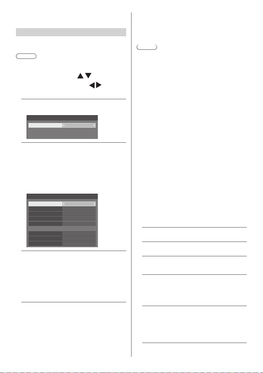
●
[Input detection] may not operate correctly depending
on the image playback device.
Failover/Failback
Automatically switches to the backup input if an
interruption of video occurs.
Note
●
MEMORY VIEWER input is excluded from this
function.
Select the item with .
1
Select the set point with
[Input change mode]
[Off]:
Disables the Backup Input function.
Failover/Failback
Input change mode Off
[Quick]:
Promptly switches to the backup input if an
interruption of video occurs.
The backup video signal needs to be in the same
format as the (main) input in use for viewing.
Upon switching to the backup input, the video and
audio adjustment values for the (main) input used
for viewing will be inherited.
Failover/Failback
Input change mode
Primary backup input
Secondary backup input
Auto switch back mode
Changing mode High speed
Backup input change
Main input
Current input
[Normal]:
Switches to the backup input if an interruption of
video occurs.
The backup video signal does not need to be in the
same format as the (main) input in use for viewing.
Upon switching to the backup input, the video and
audio adjustment values for the backup input will
be used.
Quick
HDMI1
DVI-D
Disable
Active
HDMI2
Main input
.
■ [Input change mode]: [Quick]
Promptly switches to the backup input if an
interruption of video occurs, and enables switching
between digital (HDMI1 / HDMI2 / DIGITAL LINK /
DVI-D) inputs.
Note
●
The backup video signal needs to be in the same
format as the (main) input in use for viewing.
●
Upon switching to the backup input, the video and
audio adjustment values for the (main) input used for
viewing will be inherited.
●
This function will start operating once a video signal is
detected by both the input in use for viewing and the
backup input and the [Backup input change] item is
displayed as [Active].
●
This function may not operate correctly depending on
the image playback device.
[Primary backup input]
Sets the first priority backup input.
(None) / [HDMI1] / [HDMI2] / [DIGITAL LINK] /
[DVI-D]
The input name that is of the same type as the one in
use for viewing will be greyed out.
[Secondary backup input]
Sets the second priority backup input.
(None) / [HDMI1] / [HDMI2] / [DIGITAL LINK] /
[DVI-D]
The input name that is of the same type as the one in
use for viewing will be greyed out.
[Auto switch back mode]
Sets whether or not to automatically return to the
former (main) input when the former input video
initially viewed is restored while viewing the video
of the backup input enabled by the operation of the
Backup Input function.
[Disable]:
Unreturned
[Enable]:
Returned
[Changing mode]
Select speed of input switching.
[High speed]:
If switching between the same signal formats, it is
possible to switch within 1 second.
If switching between the different signal formats,
picture noise is caused.
[Normal speed]:
If switching between the same signal formats, it is
possible to switch within 2 seconds.
If switching between the different signal formats, it
takes 3 to 4 seconds to switch but picture noise is
not caused.
English
69
Page 70
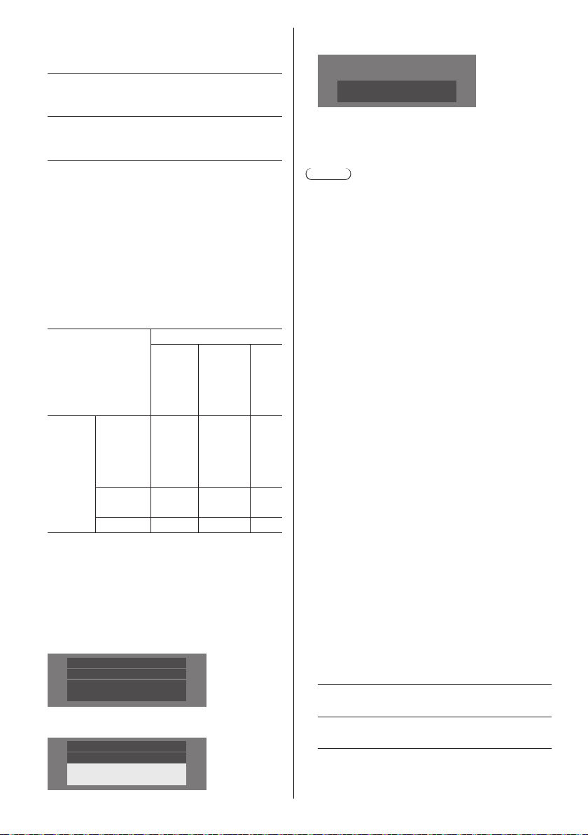
[Backup input change]
Displays whether or not operating conditions for the
Backup Input function are met.
[Inactive]:
Indicates that the conditions are not met, and
inactivates the Backup Input function.
[Active]:
Indicates that the conditions are met, and activates
the Backup Input function.
[Main input]
Displays the (main) input set by switching input.
[Current input]
Displays whether the input currently in use for viewing
is the (main) input set by switching input or the
backup one.
Setting conditions
The following table describes restrictions (available
combinations) on each setting item.
Main
HDMI1
HDMI2
DIGITAL
LINK
PC
VIDEO
USB
DVI-D
HDMI1
HDMI2
○ × ×
× × ×
Backup
DIGITAL
LINK
DVI-D
PC
VIDEO
USB × × ×
○:SelectableforbothPrimaryandSecondary.
×: Not selectable for neither Primary nor Secondary.
Recall display
Pressing <RECALL> displays any of the followings.
●
When the main input is being used for viewing and
the operating conditions for the Backup Input function
are met.
HDMI1
16:9
Main input
Backup OK
●
When the backup input, enabled by the operation of
the Backup Input function, is being used for viewing.
HDMI1
16:9
Backup Input
DVI
When the conditions for the Backup Input function
are met, the following screen is displayed.
Main input
Backup OK
■ [Input change mode]: [Normal]
Switches to the backup input if an interruption of
video occurs.
Note
●
When an analogue (PC or VIDEO) input is being
used for viewing, you cannot set an analogue (PC or
VIDEO) input as a backup input.
●
Any analogue (PC or VIDEO) input cannot be set as
[Primary backup input] or [Secondary backup input].
●
This function will start operating once a video signal is
detected by both the input in use for viewing and the
backup input and the [Backup input change] item is
displayed as [Active].
[Primary backup input]
Sets the first priority backup input.
(None) / [HDMI1] / [HDMI2] / [DIGITAL LINK] /
[DVI-D] / [PC] / [VIDEO] / [USB]
The input that is of the same type as the one in use
for viewing will be greyed out.
When an analogue (PC or VIDEO) input is being
used for viewing, you cannot set an analogue (PC or
VIDEO) input as a backup input.
Any analogue (PC or VIDEO) input cannot be set as
[Primary backup input] or [Secondary backup input].
[Secondary backup input]
Sets the second priority backup input.
(None) / [HDMI1] / [HDMI2] / [DIGITAL LINK] /
[DVI-D] / [PC] / [VIDEO] / [USB]
The input that is of the same type as the one in use
for viewing will be greyed out.
When an analogue (PC or VIDEO) input is being
used for viewing, you cannot set an analogue (PC or
VIDEO) input as a backup input.
Any analogue (PC or VIDEO) input cannot be set as
[Primary backup input] or [Secondary backup input].
[Auto switch back mode]
Sets whether or not to automatically return to the
former (main) input when the former input video
initially viewed is restored while viewing the video
of the backup input enabled by the operation of the
Backup Input function.
[Disable]:
Unreturned
[Enable]:
Returned
70
English
Page 71

[Backup input change]
Displays whether or not operating conditions for the
Backup Input function are met.
[Inactive]:
Indicates that the conditions are not met, and
inactivates the Backup Input function.
[Active]:
Indicates that the conditions are met, and activates
the Backup Input function.
[Main input]
Displays the (main) input set by switching input.
[Current input]
Displays whether the input currently in use for viewing
is the (main) input set by switching input or the
backup one.
Setting conditions
The following table describes restrictions (available
combinations) on each setting item.
Main
HDMI1
HDMI2
DIGITAL
LINK
PC
VIDEO
USB
DVI-D
HDMI1
HDMI2
○ ○ ○
×
Backup
DIGITAL
LINK
DVI-D
PC
VIDEO
USB ○ ○ ×
○:SelectableforbothPrimaryandSecondary.
: Selectable for either Primary or Secondary.
×: Not selectable for neither Primary nor Secondary.
Recall display
Pressing <RECALL> displays any of the followings.
●
When the main input is being used for viewing and
the operating conditions for the Backup Input function
are met.
HDMI1
16:9
Backup mode OK
When the conditions for the Backup Input function
are met, the following screen is displayed.
Backup mode OK
Note
●
This menu will be greyed out and cannot be set under
the following condition.
[Input search] is set to the item other than [Off].
•
(see page 68)
●
When set to the USB input, the unit determines video
signals are interrupted by judging the USB memory is
not connected to the USB terminal.
●
This function may not operate correctly depending on
the image playback device.
Audio input select
Set up the sound when a video input is selected.
Select the video input with .
1
Set the audio input with
Audio input select
HDMI1
HDMI2
DIGITAL LINK
DVI-D
PC
VIDEO AV IN
●
The illustration above shows the factory settings.
Video input Audio input
HDMI1 HDMI1 / AV IN / No audio
HDMI2 HDMI2 / AV IN / No audio
DIGITAL LINK DIGITAL LINK / AV IN /
DVI-D / PC /
VIDEO
No audio: No audio input (Mute)
When the setting for the audio input has been
changed from the factory settings, the audio input
is displayed as below.
HDMI1
HDMI2
DIGITAL LINK
AV IN
AV IN
No audio
AV IN / No audio
HDMI1
16:9
AV IN
.
●
When the backup input, enabled by the operation of
the Backup Input function, is being used for viewing.
HDMI1
16:9
Primary backup input
English
71
Page 72
Onscreen display
Set to display / hide the following Onscreen display.
●
Power on display
●
Input signal switch display
●
No signal display
●
No external media display (at USB input)
●
MUTE display after displaying the menu screen
●
Off timer remaining time display when 3 minutes
remaining
[On]:
Displays the Onscreen display.
[Off]:
Hides the Onscreen display.
Initial input
Adjusts the input signal when the unit is turned on.
[Off] / [HDMI1] / [HDMI2] / [DIGITAL LINK] /
[DVI-D] / [PC] / [VIDEO] / [USB] / [MEMORY
VIEWER]
Note
This menu is available only when [Input lock] is [Off].
(see page 72)
Initial VOL function
Enables/Disables [Initial VOL function] when the unit is
turned on.
[Off]:
It will be the sound volume level which had been
set before the power of the unit was turned off.
[On]:
It will be the sound volume level set for [Initial VOL
level].
Initial VOL level
Sets the sound volume when [Initial VOL function] is
enabled.
Note
●
Outputs with the set volume when [Initial VOL
function] is [On].
●
When [Maximum VOL function] is [On], the volume
cannot be set to the level higher than the level set for
[Maximum VOL level].
Maximum VOL function
Enables/Disables [Maximum VOL function].
[Off]:
The sound volume level can be set up to 100
(maximum).
[On]:
The volume cannot be set to the level higher than
the level set for [Maximum VOL level].
Maximum VOL level
Sets the sound volume when [Maximum VOL function]
is enabled.
Note
●
Outputs with the set volume when [Maximum VOL
level] in [On] state is selected on the menu.
●
When the [Maximum VOL function] is switched from
[Off] to [On], if the [Maximum VOL level] is set lower
than the [Initial VOL level], the [Initial VOL level]
automatically becomes the same as the [Maximum
VOL level].
Input lock
Locks the input switch operation.
[Off] / [HDMI1] / [HDMI2] / [DIGITAL LINK] / [DVI-D]
/ [PC] / [VIDEO] / [USB] / [MEMORY VIEWER]
Note
●
Input switch can be used when this is set to [Off].
Button lock
Limits operation of the buttons on the unit.
[Off]:
All the buttons on main unit can be used.
[On]:
All button operations except for the <Main Power
On / Off button> are disabled.
[MENU & ENTER]:
Locks <MENU (Unit)> and <ENTER (Unit)>
buttons.
■ To set [Button lock]
Set with the buttons on the unit.
[Off]:
Press <+ (Unit)> for 4 times.
Press <INPUT (Unit)> for 4 times.
Press <- (Unit)> for 4 times.
Press <ENTER (Unit)>.
[On]:
Press <- (Unit)> for 4 times.
Press <ENTER (Unit)> for 4 times.
Press <+ (Unit)> for 4 times.
Press <ENTER (Unit)>.
[MENU & ENTER]:
Press <ENTER (Unit)> for 4 times.
Press <+ (Unit)> for 4 times.
Press <INPUT (Unit)> for 4 times.
Press <ENTER (Unit)>.
Note
●
About how to reset the settings to defaults:
“Initialization” (see page 76)
72
English
Page 73
Controller user level
Limits operation of the buttons on the remote control.
[Off]:
You can use all of the buttons on the remote control.
[User1]:
You can only use <Standby (ON/OFF) button>,
<INPUT>, <RECALL>, <MUTE>, <VOL +> and
<VOL -> buttons on the remote control.
[User2]:
You can only use <Standby (ON/OFF) button> on
the remote control.
[User3]:
Locks all the buttons on the remote control.
Note
●
About how to reset the settings to defaults:
“Initialization” (see page 76)
PC auto setting
Sets the operational mode of the automatic position
adjustment in the [Position] menu.
[Off]:
Automatic position adjustment starts when <AUTO
SETUP> is pressed on the remote control or
automatic position adjustment is executed from the
[Position] menu.
[On]:
Other than remote control or menu operation,
automatic position adjustment starts:
When the display power is turned ON.
•
When the input signal is switched.
•
Off-timer function
Enables / disables Off timer function.
[Enable]:
Enables the [Off-timer function].
[Disable]:
Disables the [Off-timer function].
Note
●
When [Disable] is set, the Off-timer is cancelled.
Initial startup
Sets the power mode of the unit for when the power
recovers from failure or after plugging off and in again.
[Last memory]:
Power returns in as the same state as before the
power interruption.
[On]:
Power returns in power On.
(Power Indicator: green)
[Standby]:
Power returns in standby mode.
(Power Indicator: red/orange)
Note
●
When using multiple displays, [Standby] is preferred
to be set in order to reduce a power load.
Display ID
Sets ID number when controlling the Display with
[Controller ID function] and [Serial ID function].
0 ‒ 100 (Standard value: 0)
Controller ID function
Enables/Disables the ID remote control function.
To operate this function, please purchase ID remote
controller sold separately. (see page 119)
[Off]:
Disables the ID remote control function. (Can be
operated as normal remote control.)
[On]:
Enables the ID remote control function.
Effective on switching to [On].
Note
●
To use the ID remote control function, setting ID
numbers both for the remote control and for the
display unit is required.
For ID number setting for the remote control
and display unit, see page 119 and [Display ID]
respectively.
●
About how to reset the settings to defaults:
“Initialization” (see page 76)
Serial ID function
Set to control external control with the PC connected to
SERIAL terminal according to the Display’s ID number
(Panel ID).
[Off]:
Disables external control by the ID.
[On]:
Enables the external control by the ID.
English
73
Page 74
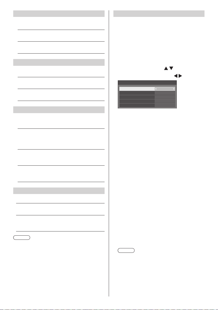
Serial response(Normal)
Sets whether to send the response command to normal
commands without ID.
[Off]:
Does not respond. (Including the inquiry command)
[On]:
Responds.
Serial response(ID all)
Sets whether to respond to the command or not, when
serial command of ID No “0” is received.
[Off]:
Does not respond.
[On]:
Responds.
Serial daisy chain position
Set the first and last terminals in the chain when the
SERIAL IN/OUT terminal of this unit is connected using
a daisy chain scheme.
[---]:
When controlling this unit alone with serial control,
or connecting at a position other than the first and
last terminals in a daisy chain
[Top ]:
When connecting at the first terminal in a daisy
chain
[End]:
When connecting at the last terminal in a daisy
chain
LAN control protocol
Select the LAN control protocol.
[Protocol 1]:
Control with the Panasonic Display sequence.
[Protocol 2]:
Control with the sequence that is compatible with
Panasonic Projector.
Note
●
For PJLink and WEB browser control, the operation is
possible regardless of the setting.
●
When operating the “Early Warning Software” or
“Multi Monitoring & Control Software”, select [Protocol
2].
Information timing
Set up the informing manner for no signal or
temperature rising.
During RS-232C controls:
Warning or error message sent from the display
automatically.
During LAN controls:
Acquire the warning or error message from the
display.
Select the item with .
1
Select the set point with
Information timing
No signal warning
No signal warning timing
No signal error
No signal error timing
Temperature warning
[No signal warning]
When set to [On], the display sends out the no signal
warning.
[No signal warning timing]
Set up the detecting time for no signal warning.
(Range:01‒60,Interval:1minute)
[No signal error]
When set to [On], the display sends out the no signal
error.
[No signal error timing]
Set up the detecting time for no signal error.
(Range:01‒90,Interval:1minute)
●
The warning of [No signal warning] and the error of
[No signal error] are not sent when the no signal state
is detected through any of the following functions:
[No signal power off], [HDMI1 power management],
[HDMI2 power management], [DIGITAL LINK
power management], [DVI-D power management],
[PC power management] (see page 51)
Setting Example:
●
If there is no signal when [PC IN] is input, [PC
power management] is activated first and the
Display enters the standby mode.
[No signal warning timing]: 5 minutes
[No signal error timing]: 10 minutes
[PC power management]: [On] (60 seconds)
Note
●
The [No signal error timing] cannot be set shorter
than [No signal warning timing].
●
Even when a USB memory is connected, if there
is no playable file, the unit determines no signal is
present.
[Temperature warning]
When set to [On], the display sends out the warning
message.
10min
On
5min
On
On
.
74
English
Page 75
Power on screen delay
You can set the power-on delay time of the displays to
reduce the power load, when you press <Main Power
On / Off button> to turn on the multiple displays that are
set together.
Set each display’s setting individually.
[Off]:
The display will be turned on at the same time as
<Main Power On / Off button> is pressed.
[Auto]:
Sets the delay time automatically according to the
number set for [Display ID].
The delay time is determined by multiplying
[Display ID] × 0.3 seconds.
Example:
When [Display ID]is3→0.9seconds
1 ‒ 30:
Set the power-on delay time (second).
After pressing <Main Power On / Off button>,
the display will be powered on with time delay
depending on this setting.
Note
●
While this function is working, the power indicator is
blinking green.
●
This function also works when the power recovers
from failure or after plugging off and in again the
power cord.
Clock display
Sets to display / hide the clock.
[Off]:
Hides the clock.
[On]:
Displays the clock.
Note
●
The clock is displayed at the lower left of the screen
when <RECALL> button is pressed.
Display duration is approx. 5 seconds.
●
When current date and time is not set, the clock is
not displayed even when [Clock display] is [On]. (see
page 57)
Power on message(No activity power
off)
Sets to show/hide [No activity power off] precautions
when the power is turned on.
[On]:
The warning precautions are shown when the
power is turned on.
[Off]:
The warning precautions are not shown when the
power is turned on.
Note
●
This setting is enabled only when [No activity power
off] is [Enable] (see page 55).
Power on message(Power
management)
Sets to show/hide an information message that tells
the power has been turned off by “Power management”
function when the power is turned on.
[On]:
The information is shown when the power is turned
on.
[Off]:
The information is not shown when the power is
turned on.
Note
●
This setting is enabled only when “Power
management” function is [On] (see page 51).
POWER button lock
Sets the lock setting for the display <Main Power On /
Off button>.
[On]:
<Main Power On / Off button> operation is
disabled.
[Off]:
<Main Power On / Off button> operation is
enabled.
Note
●
This function is only for TH-65SF2U, TH-55SF2U,
TH-49SF2U and TH-43SF2U.
English
75
Page 76
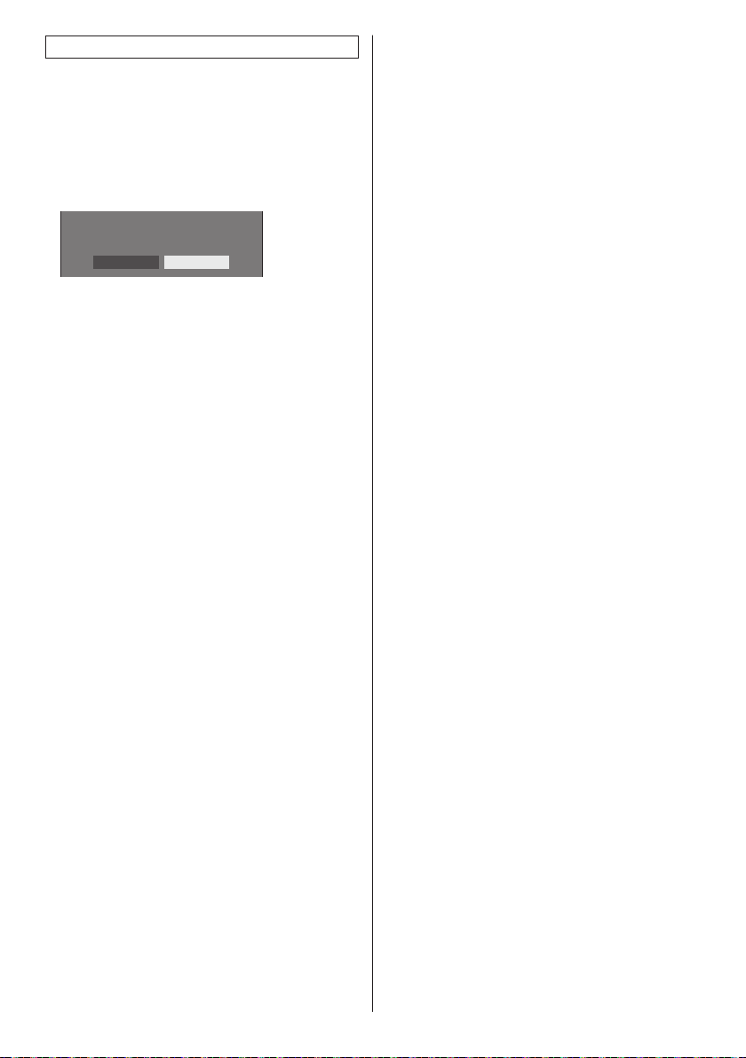
Initialization
When both main unit buttons and remote control buttons
are disabled due to the [Button lock], [Controller user
level] and [Controller ID function] settings, set all the
values [Off] so that all the buttons are enabled again.
Press <- (Unit)> together with <RETURN>
and hold for more than 5 seconds.
[Shipping] is displayed and the lock is released when
it disappears.
Shipping
YES NO
●
Settings for [Button lock], [Controller user level]
and [Controller ID function] will be back to [Off].
76
English
Page 77
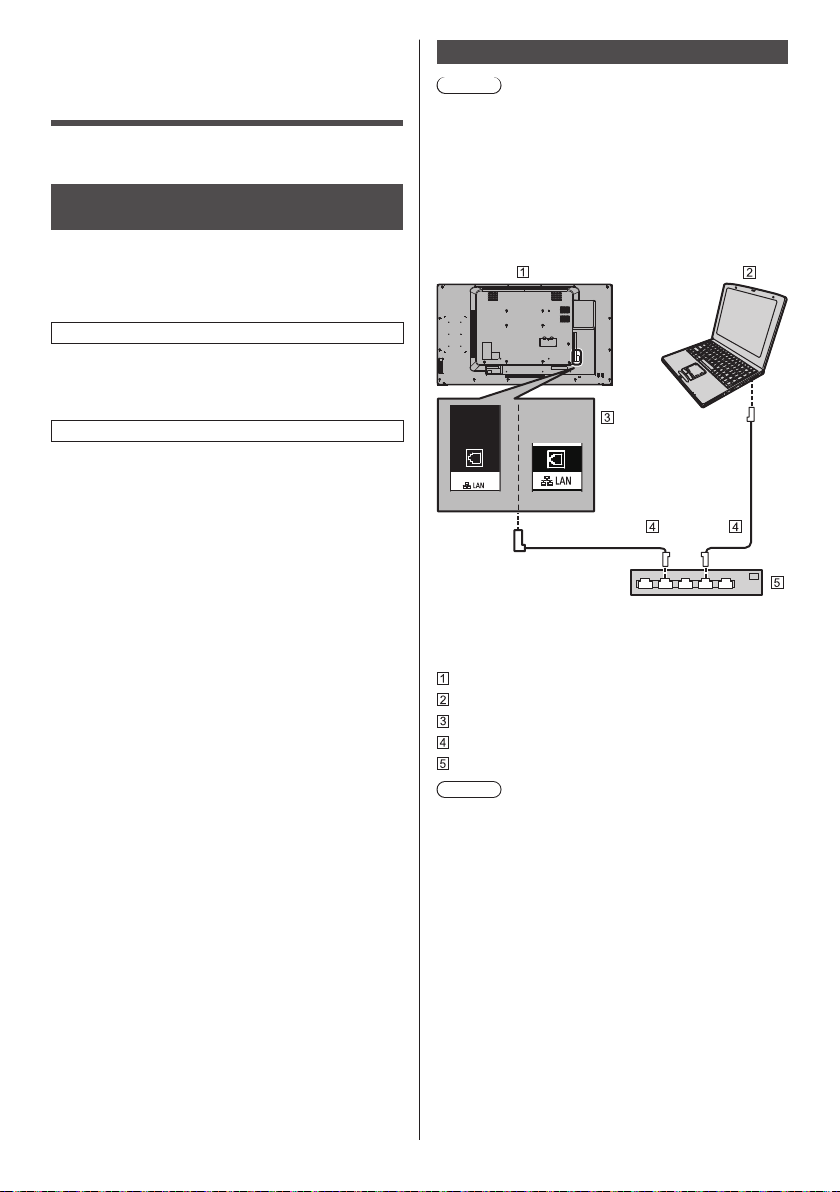
Using Network Function
This unit has a network function and you can control the
Display connected to the network using your computer.
Necessary environment for computers to be connected
First of all, confirm your computer whether it has a wired
LAN.
Before connecting the Display to the computer, be sure
to check the following settings.
Check 1: About LAN cable
●
Connect the cable properly.
●
Use LAN cable that is compatible with category 5 or
above.
Check 2: Wired LAN settings
Computer with a built-in wired LAN function
●
Switch on the wired LAN.
Computer without a built-in wired LAN function
●
Check that your wired LAN adapter is recognized
properly and it is switched on.
●
Install the wired LAN adapter driver beforehand.
For details on how to install the driver, refer to the
instructions accompanying the wired LAN adapter.
■ About Web Browser
Web Browser is necessary to use WEB control.
●
Compatible OS:
Windows, Mac OS
●
Compatible Web Browser:
Internet Explorer 7.0 / 8.0 / 9.0 / 10.0 / 11.0
(Windows)
Safari 4.x / 5.x / 6.x (Mac OS)
Example of network connection
Note
●
To use the network function, set each item in
[Network settings] and make sure to set [Network
control] to [On].
(see page 59)
When it is set to [On], power indicator lights orange
under the condition of power “Off” with remote control
(stand-by state).
■ LAN Terminal connection
DIGITAL LINK
*1 *2
*
1: TH-65SF2E
*
2: TH-65SF2U, TH-55SF2U, TH-49SF2U, TH-43SF2U,
TH-55SF2E, TH-49SF2E, TH-43SF2E
Display (Back of the unit)
PC
DIGITAL LINK / LAN Terminal
LAN cable (commercially available)
Hub or broadband router
Note
●
For LAN cable, use shielded cable, otherwise picture
noise may be caused.
●
Make sure the broadband router or hub supports
100BASE-TX.
●
Touching the LAN Terminal with a statically charged
hand (body) may cause damage to the device due to
its discharge.
Do not touch the LAN Terminal or the metal part of
the LAN cable.
●
For instructions on connection, consult your network
administrator.
English
77
Page 78
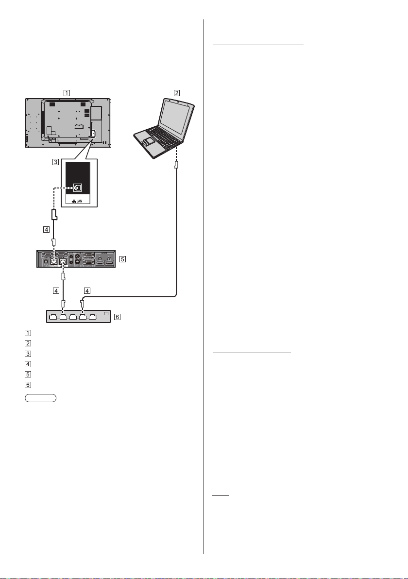
■ DIGITAL LINK Terminal connection
A twisted pair cable transmitter, such as the Panasonic
device that supports DIGITAL LINK output (ETYFB100G, ET-YFB200G) uses twisted pair cables to
transmit inputted video and audio signals, and these
digital signals can be input to the Display via the
DIGITAL LINK terminal.
DIGITAL LINK
Display (Back of the unit)
PC
DIGITAL LINK / LAN Terminal
LAN cable (commercially available)
Example: Panasonic ET-YFB100G
Hub or broadband router
Note
●
When using a DIGITAL LINK connection, set each
item in [Network settings]. (see page 59)
Precautions for use while connecting with a twisted
pair cable transmitter
About installation / connection
●
Ask a professional or the dealer to carry out the
cable wiring work for DIGITAL LINK connections.
Insufficient wiring work may cause the inability to
apply the cable transmission characteristics and
cropped or fuzzy images and sounds.
●
The transmission distance between the twisted
pair cable transmitter and the device is normally
up to 100 meters. When the transmitter supports
[Long reach] communication method, the
transmittable distance is up to 150 m. Please note
that if exceeding the limit, video or audio may be
interrupted, or malfunction may be caused during
LAN communication. Furthermore, when connecting
using [Long reach] communication method,
depending on the specification of the transmitters,
transmittable video signals or the distance may be
limited.
●
Do not use a hub between the twisted pair cable
transmitter and the device.
●
When connecting the Display using the twisted pair
cable transmitter (receiver) of other manufacturer,
do not use another twisted pair cable transmitter
between the twisted pair cable transmitter of other
manufacturer and this device. The images and
sounds may be interrupted or become unstable.
●
If possible, lay the cable extended and not coiled in
order to minimize both external and internal noise.
●
Lay out cables of the twist pair cable transmitter and
this product away from other cables, especially from
the power supply cable.
●
When laying multiple cables, keep them together as
close as possible running parallelly and not bundled.
●
After laying the cable(s), check that the signal quality
in [DIGITAL LINK status] is -12 dB or below.
About Twisted pair cables
●
Between the twisted pair cable transmitter and
the device, use a LAN cable that conforms to the
following conditions.
It meets or exceeds CAT5e standards
•
It is a straight cable
•
It is a shielded cable (with a connector)
•
It is a solid cable
•
●
When laying the cable(s), use an instrument such as
a cable tester or cable analyser and check whether
the cable characteristics are CAT5e or above. When
using a relay connector along the path, also include
this in the measurements.
●
Do not pull cables hard. Also, avoid bending or
folding them forcefully.
Other
●
This device is compatible with Panasonic devices that
support DIGITAL LINK output (ET-YFB100G, ETYFB200G). For the twisted pair cable transmitter of
other manufacturers, see the web site:
https://panasonic.net/cns/prodisplays/solutions/
digital_link/compatible_equipment/
78
English
Page 79
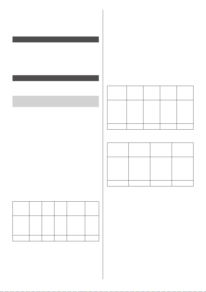
●
Panasonic has tested other manufacturers’ devices
according to our check items. This will not guarantee
all the operations. For operation and performance
defects caused by other manufacturers’ devices,
contact each manufacturer.
Command control
Network function of the unit can control the unit in the
same way as serial control from a network.
Supported commands
Commands used in the serial control are supported.
(see page 24)
Control Command via LAN
The communication differs whether [Options] - [LAN
control protocol] is set to [Protocol 1] or [Protocol 2].
1. When [LAN control protocol] is set
to [Protocol 1].
Communicates using the display-specific protocol.
■ When the WEB control administrator
privileges password has been set (Protect
mode)
Connection method
Obtain the display’s IP address and the port number
1
(Default is 1024), and request connection to the
display.
The IP address and the port number can be obtained
from the following menus.
IP address:
•
[Setup]→[Network settings]→[LAN setup] or
[Network status]
Port number:
•
[Setup]→[Network settings]→[LAN setup]
●
For more detail of the settings, see page 59.
The display responds.
2
Response data
[ ]
0x20
Random
number
part
[zzzzzzzz]
(ASCII code
hex number)
Data part Space Mode Space
[PDPCONTROL]
(ASCII
character
string)
10 bytes 1 byte 1 byte 1 byte 8 bytes 1 byte
Mode: 1 = Protect mode
[ ]
0x20
[1]
0x31
Last
terminal
symbol
(CR)
0x0d
Hash the following data with the MD5 algorithm, and
3
generate a 32-byte hash value.
[zzzzzzzzyyyyy]
zzzzzzzz :
8-byte random number obtained in step 2
yyyyy :
Password of the WEB control administrator
privileges user
●
Default user name and password are as follows:
User name: dispadmin
Password: @Panasonic
Command transmission method
Transmit in the following command format
Transmitted data
(see
0x02
Control
symbol
(STX)
0x02
Data part
Control
command
(ASCII
character
string)
Data part
Control
command
(ASCII
character
string)
Header
Hash value
“Connection
method”)
32 bytes 1 byte Undefined 1 byte 1 byte
Received data
Control
symbol
(STX)
1 byte Undefined 1 byte 1 byte
Control
symbol
(ETX)
Control
symbol
(ETX)
0x03
terminal
symbol
0x03
Last
terminal
symbol
(CR)
0x0d
Last
(CR)
0x0d
English
79
Page 80
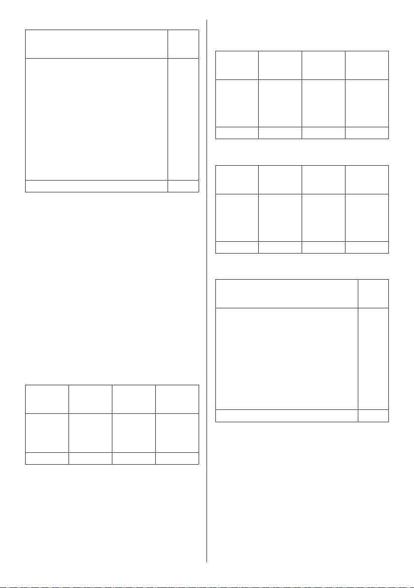
Error response
Error message
“ERR1” : Undefined control
“ERR2” : Out of parameter
“ERR3” : Busy status or
“ERR4” : Timeout or reception
“ERR5” : Wrong data length
“PDPCONTROL
ERRA”
4 bytes or 15 bytes 1 byte
command
range
reception invalid
period
invalid period
: Mismatching of
password
terminal
symbol
■ When the WEB control administrator
privileges password has not been set (Nonprotect mode)
Connection method
Obtain the display’s IP address and the port number
1
(Default is 1024), and request connection to the
display.
The IP address and the port number can be obtained
from the following menus.
IP address:
•
[Setup]→[Network settings]→[LAN setup] or
[Network status]
Port number:
•
[Setup]→[Network settings]→[LAN setup]
●
For more detail of the settings, see page 59.
The display responds.
2
Response data
Data part Space Mode
[PDPCONTROL]
(ASCII
character
string)
10 bytes 1 byte 1 byte 1 byte
Mode: 0 = Non-protect mode
[ ]
0x20
[0]
0x30
Last
terminal
symbol
(CR)
0x0d
Last
(CR)
0x0d
Command transmission method
Transmit in the following command format
Transmitted data
Control
symbol
(STX)
0x02
1 byte Undefined 1 byte 1 byte
Received data
Control
symbol
(STX)
0x02
1 byte Undefined 1 byte 1 byte
Error response
Error message
Data part
Control
command
(ASCII
character
string)
Data part
Control
command
(ASCII
character
string)
“ERR1” : Undefined control
“ERR2” : Out of parameter
“ERR3” : Busy status or
“ERR4” : Timeout or reception
“ERR5” : Wrong data length
4 bytes 1 byte
Control
symbol
(ETX)
0x03
Control
symbol
(ETX)
0x03
command
range
reception invalid
period
invalid period
Last
terminal
symbol
(CR)
0x0d
Last
terminal
symbol
(CR)
0x0d
Last
terminal
symbol
(CR)
0x0d
80
English
Page 81
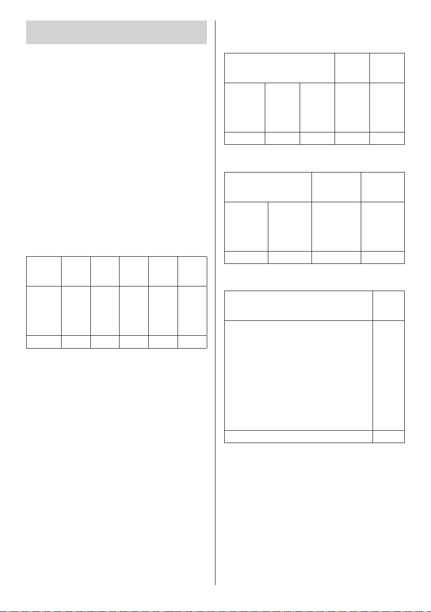
2. When [LAN control protocol] is set
to [Protocol 2].
Communicates with the same protocol as that of a
Panasonic projector
■ When the WEB control administrator
privileges password has been set (Protect
mode)
Connection method
Obtain the display’s IP address and the port number
1
(Default is 1024), and request connection to the
display.
The IP address and the port number can be obtained
from the following menus.
IP address:
•
[Setup]→[Network settings]→[LAN setup] or
[Network status]
Port number:
•
[Setup]→[Network settings]→[LAN setup]
●
For more detail of the settings, see page 59.
The display responds.
2
Response data
[ ]
0x20
Random
number
part
[zzzzzzzz]
(ASCII
code
hex
number)
terminal
symbol
Data part Space Mode Space
[NTCONTROL]
(ASCII
character
string)
9 bytes 1 byte 1 byte 1 byte 8 bytes 1 byte
Mode: 1 = Protect mode
Hash the following data with the MD5 algorithm, and
3
generate a 32-byte hash value.
[xxxxxx:yyyyy:zzzzzzzz]
[ ]
[1]
0x20
0x31
xxxxxx :
WEB control administrator privileges user name
yyyyy :
Above administrator privileges user password
●
Default user name and password are as
follows:
User name: dispadmin
Password: @Panasonic
zzzzzzzz :
8-byte random number obtained in step 2
Last
(CR)
0x0d
Command transmission method
Transmit in the following command format
Transmitted data
Header Data part
Hash value
(see
“Connection
method”)
32 bytes 1 byte 1 byte Undefined 1 byte
Received data
‘0’
0x30
1 byte 1 byte Undefined 1 byte
Error response
Error message
“ERR1” : Undefined control
“ERR2” : Out of parameter range
“ERR3” : Busy status or
“ERR4” : Timeout or reception
“ERR5” : Wrong data length
“ERRA” : Mismatching of
4 bytes 1 byte
‘0’
0x30
Header Data part
0x30
‘0’
0x30
command
reception invalid period
invalid period
password
‘0’
Control
command
(ASCII
character
string)
Control
command
character
terminal
symbol
(ASCII
string)
terminal
symbol
(CR)
0x0d
terminal
Last
(CR)
0x0d
Last
Last
symbol
(CR)
0x0d
English
81
Page 82
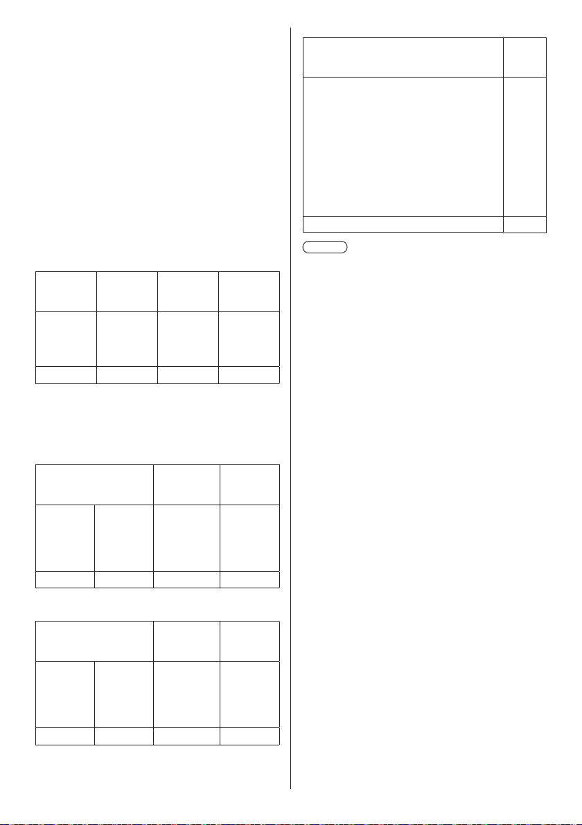
■ When the WEB control administrator
privileges password has not been set (Nonprotect mode)
Connection method
Obtain the display’s IP address and the port number
1
(Default is 1024), and request connection to the
display.
The IP address and the port number can be obtained
from the following menus.
IP address:
•
[Setup]→[Network settings]→[LAN setup] or
[Network status]
Port number:
•
[Setup]→[Network settings]→[LAN setup]
●
For more detail of the settings, see page 59.
The display responds.
2
Response data
Data part Space Mode
[NTCONTROL]
(ASCII
character
string)
9 bytes 1 byte 1 byte 1 byte
Mode: 0 = Non-protect mode
Command transmission method
Transmit in the following command format
Transmitted data
Header Data part
‘0’
0x30
1 byte 1 byte Undefined 1 byte
[ ]
0x20
‘0’
0x30
[0]
0x30
Control
command
(ASCII
character
string)
Last
terminal
symbol
(CR)
0x0d
Last
terminal
symbol
(CR)
0x0d
Error response
Error message
“ERR1” : Undefined control
“ERR2” : Out of parameter
“ERR3” : Busy status or
“ERR4” : Timeout or reception
“ERR5” : Wrong data length
4 bytes 1 byte
Note
●
With some of the commands, a part of character
string of the transmitted data may not be included in
the received data.
●
Consult your local Panasonic dealer for detail
instructions on command usage.
For more details, visit the following web site.
https://panasonic.net/cns/prodisplays/
command
range
reception invalid
period
invalid period
Last
terminal
symbol
(CR)
0x0d
Received data
Header Data part
Control
‘0’
0x30
1 byte 1 byte Undefined 1 byte
English
82
‘0’
0x30
command
character
(ASCII
string)
Last
terminal
symbol
(CR)
0x0d
Page 83
PJLink protocol
The unit’s Network function is compatible with PJLink
Class 1. The following operations can be performed from
a computer when PJLink protocol is used.
●
Setting the Display
●
Querying the Display status
Supported commands
The commands to control the unit with PJLink protocol
are as follows.
Command Control
POWR Power control
0: Standby
1: Power On
POWR? Power status query
0: Standby
1: Power On
INPT Input switch
11: PC IN input (PC)
21: AV IN input (VIDEO)
31: HDMI 1 input (HDMI1)
32: HDMI 2 input (HDMI2)
33: DIGITAL LINK input
(DIGITAL LINK)
DVI-D IN input (DVI-D)
34: DVI-D IN input (DVI-D)
41: USB input (USB)
42: MEMORY VIEWER input
(MEMORY VIEWER)
INPT? Input switch query
11: PC IN input (PC)
21: AV IN input (VIDEO)
31: HDMI 1 input (HDMI1)
32: HDMI 2 input (HDMI2)
33: DIGITAL LINK input
(DIGITAL LINK)
DVI-D IN input (DVI-D)
34: DVI-D IN input (DVI-D)
41: USB input (USB)
42: MEMORY VIEWER input
(MEMORY VIEWER)
1
*
2
*
1
*
2
*
Command Control
AVMT Shutter control
10: Picture On
(picture mute deactivated)
11: Picture Off
(picture on mute)
20: Audio On
(audio mute deactivated)
21: Audio Off
(audio on mute)
30: Shutter mode Off
(picture and audio mute
deactivated)
31: Shutter mode On
(picture and audio on mute)
AVMT? Shutter control query
11: Picture Off (picture on mute)
21: Audio Off (audio on mute)
30: Shutter mode Off
(picture and audio mute
deactivated)
31: Shutter mode On
(picture and audio on mute)
ERST? Error status query
First byte: 0
Second byte: 0
Third byte: 0
Fourth byte: 0
Fifth byte: 0
Sixth byte: Other error. 0 or 2.
●
Meaning of 0, 2.
0: Error is not detected,
2: Error
LAMP? Lamp status query
Not supported
INST? Input switch list query
11: PC IN input (PC)
21: AV IN input (VIDEO)
31: HDMI 1 input (HDMI1)
32: HDMI 2 input (HDMI2)
33: DIGITAL LINK input
(DIGITAL LINK)
DVI-D IN input (DVI-D)
34: DVI-D IN input (DVI-D)
41: USB input (USB)
42: MEMORY VIEWER input
(MEMORY VIEWER)
NAME? Display name query
The name selected in [Display name]
is returned.
INF1? Manufacturer name query
Returns “Panasonic”.
1
*
2
*
English
83
Page 84
Command Control
INF2? Model name query
Returns “65SF2U” / “65SF2E”.
(Example: 65-inch SF2U / SF2E
model)
INFO? Other information query
Returns version number.
CLSS? Class information query
Returns “1”.
*
1: For TH-65SF2E only
*
2: For TH-65SF2U, TH-55SF2U, TH-49SF2U,
TH-43SF2U, TH-55SF2E, TH-49SF2E, TH-43SF2E
only
PJLink security authentication
The password used for PJLink is the same as the
password set for the WEB control. (see page 86)
When using PJLink without security authorization, set
use without the password for administrator privileges
and the password for user privileges of Web browser
control.
●
Concerning the specification of PJLink, see the web
site of Japan Business Machine and Information
System Industries Association (JBMIA) below:
http://pjlink.jbmia.or.jp/english/index.html
Multi Monitoring & Control Software
This unit supports the early warning software “Multi
Monitoring & Control Software” which monitors and
controls devices (projectors or displays) connected to
an intranet, and detects signs of abnormality of such
devices that may arise in future.
As for the early warning function, the maximum number
of devices that can be registered to monitor differs
according to the type of license.
Up to 2 048 devices can be registered for free for
a maximum of 90 days after the installation to the
computer has completed.
●
For more details, visit the following web site.
https://panasonic.net/cns/prodisplays/
●
About early warning function, visit the following web
site.
https://panasonic.net/cns/prodisplays/pass/
Video Wall Manager
This unit supports the “Video Wall Manager” software
which adjusts multiple displays simultaneously or
separately on one computer without rearranging cables.
●
For more details, visit the following web site.
https://panasonic.net/cns/prodisplays/
Content Management Software
This unit supports “Content Management Software” to
create schedule data on a PC required to play back
still pictures and motion pictures. (Supports Ver.3.0 or
later. For the caption display function, supports Ver.3.1
or later.)
●
For more details, visit the following web site.
https://panasonic.net/cns/prodisplays/
84
English
Page 85
Connecting with
Using Web Browser
LAN
Note
●
To use the network function, set each item in
[Network settings] and be sure to set [Network
control] to [On]. (see page 59)
Computer operation
Turn on the computer.
1
Make the network setting according
2
to your system administrator.
When the Display settings are the default settings
(see page 60), the computer can be used with the
following network settings.
IP address 192.168.0.9
Subnet mask 255.255.255.0
Gateway 192.168.0.1
Control
You can use a Web browser to control the unit and set
up a network and password.
Before Using Web Browser Control
To use the Web browser control, the unit and computer
set ups are required.
■ About Web Browser
Set each item in [Network settings] and be sure to
set [Network control] to [On]. (see page 59)
Note
●
Even if the setting is set to [Off], the Web browser
control screens that do not control this unit (display
information [Status], detailed settings [Detailed set
up] and password change [Change password])
operate.
■ Computer Setup
Disable the proxy server settings and enable JavaScript.
●
The setting procedure differs depending on the
software version.
Please refer to description in HELP, etc. of the software.
(Windows)
Windows 7 is used as an example.
Disable proxy server settings
1 Display [Internet Properties] window.
Click [Start] - [Control Panel] -
[Network and Internet] - [Internet Options].
●
If the on screen display looks different, please set
[View by:] to [Category].
2 Click the [Connections] tab and then [LAN Settings].
3 Deselect the [Use automatic configuration script] and
[Use a proxy server for your LAN] boxes.
4 Click [OK].
Enable JavaScript
1 Display [Internet Properties] window.
Click [Start] - [Control Panel] -
[Network and Internet] - [Internet Options].
●
If the on screen display looks different, please set
[View by:] to [Category].
2 Set the security level on the [Security] tab to [Default
Level]. Alternatively enable [Active scripting] from the
[Custom Level] button.
(Mac)
Disable proxy server settings
1 From the [Safari] menu, click [Preferences].
General screen is displayed.
2 From the [Advanced] tab, click the [Change
Settings…] button next to [Proxies].
Click [Proxies] and set up a proxy server.
3 Deselect the [Web Proxy] and [Automatic Proxy
Configuration] boxes.
4 Click [Apply Now].
English
85
Page 86
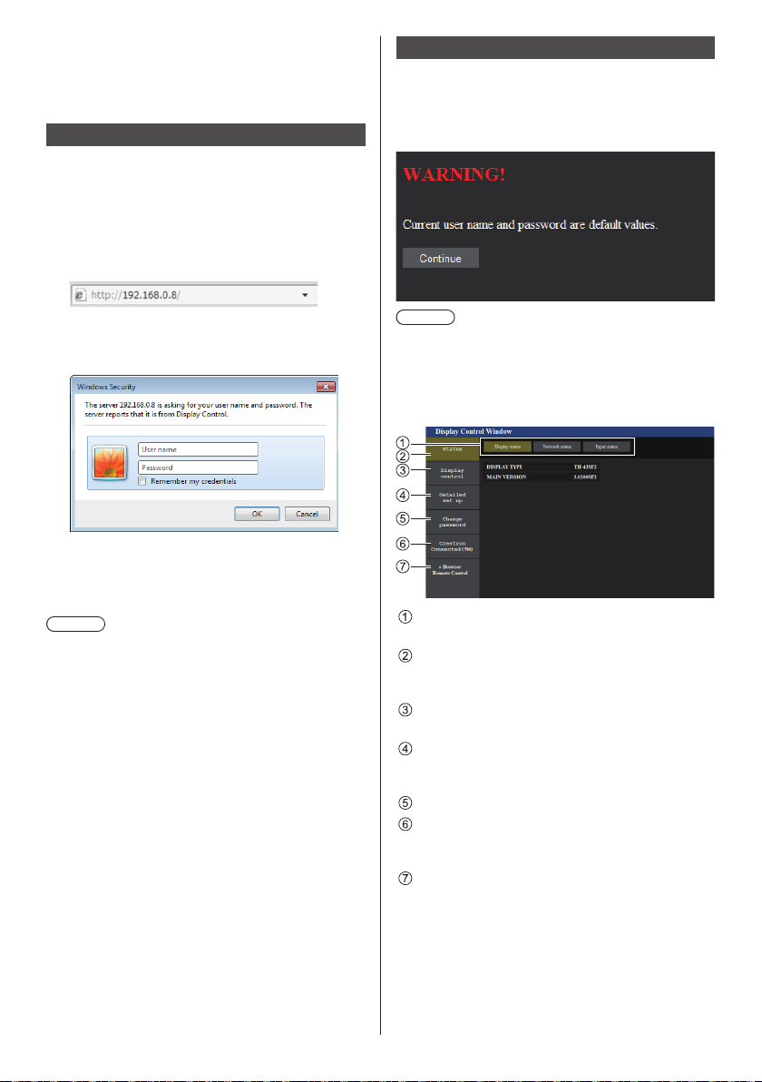
Enable JavaScript
1 Display [Security] of Safari.
2 Select [Enable JavaScript] under [Web content].
Access from Web Browser
Access to the TOP screen of the Web browser control
using a Web browser.
Start your Web browser.
1
Enter the IP address set with the
2
[LAN setup] of the unit.
(see page 59)
Operating with Web Browser
■ WARNING display page
In case the following warning page is displayed when
you log in with the factory default user name and
password, click the [Continue] button to display the
[Display Control Window] page.
Enter the user name and password
3
when the Authentication screen is
displayed.
Click [OK].
4
After logged in, the TOP screen of the Web Browser
Control is displayed.
Note
●
The password used here is the same password
used for command control and the PJLink security
authentication.
●
Default user name and password are as follows:
User name: dispuser (user rights)
dispadmin (administrator rights)
Password: @Panasonic
Change password first.
In case the warning screen is displayed when you log
in with the factory default user name and password,
click the [Continue] button.
●
The password can be changed on the Password
Setup screen after logging in (see page 87). Log in
with administer privileges to change this.
●
If a wrong user name/password is entered 3 times when
you log in, the field will be locked for several minutes.
●
When using “Crestron Connected™” (see page 93),
log in with the administrator rights.
●
Under no circumstances, Panasonic Corporation or
its associated companies will ask customers their
password directly.
Even if you are asked directly, please do not reveal
your password.
Note
●
It is recommended to change password on the
[Change password] page.
●
Depending on the browser, displayed operations may
change.
■ Description of each section
Page tab
Click these to switch pages.
[Status]
Click this item, and the status of the Display is
displayed.
[Display control]
Click this item to display the Display control page.
[Detailed set up]
Click this item to display the advanced settings
page.
[Change password]
[Crestron Connected™]
Click this item to display the Crestron Connected™
operation page.
[Browser Remote Control]
Click this item to display the Browser Remote
Control on the WEB browser, which is the same as
the supplied remote control.
86
English
Page 87
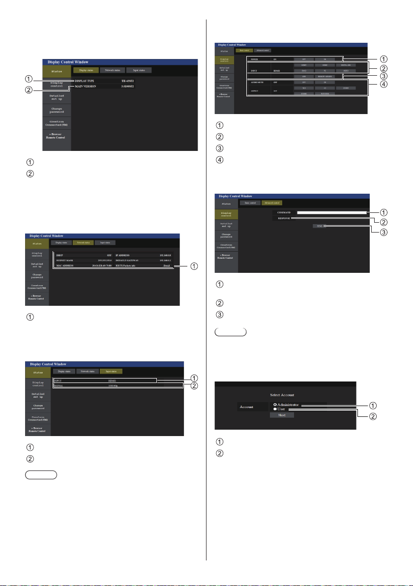
Display status page
1
2
Click [Status]→[Display status].
This page displays the Display statuses established for
the items shown below.
Displays the type of Display.
Displays the firmware version of the Display main
unit.
Network status page
Click [Status]→[Network Status].
Displays the current configuration information of the
network.
Displays the configuration details of wired LAN.
Input information page
Displays the input information of this unit.
Click [Status]→[Input status].
Basic control page
Click [Display control]→[Basic control].
Power On/Off control
Use these to select the input signals
AUDIO mute
Switches aspect mode
Detail control page
Click [Display control]→[Advanced control].
Enter a command. Use the same command used for
the serial control.
Response from the unit is displayed.
Command is sent and run.
Note
●
After the settings are changed, it may take a while till
the display status is displayed.
Change Use name / Password page
Click [Change password].
Displays the information of the input terminal.
Displays the information of the input signal.
Note
●
If an input is other than USB input, the name of the
input signal is displayed.
●
In the case of USB input, the name of the file being
played is displayed.
●
[----] is displayed in standby mode.
Administrator
User
English
87
Page 88
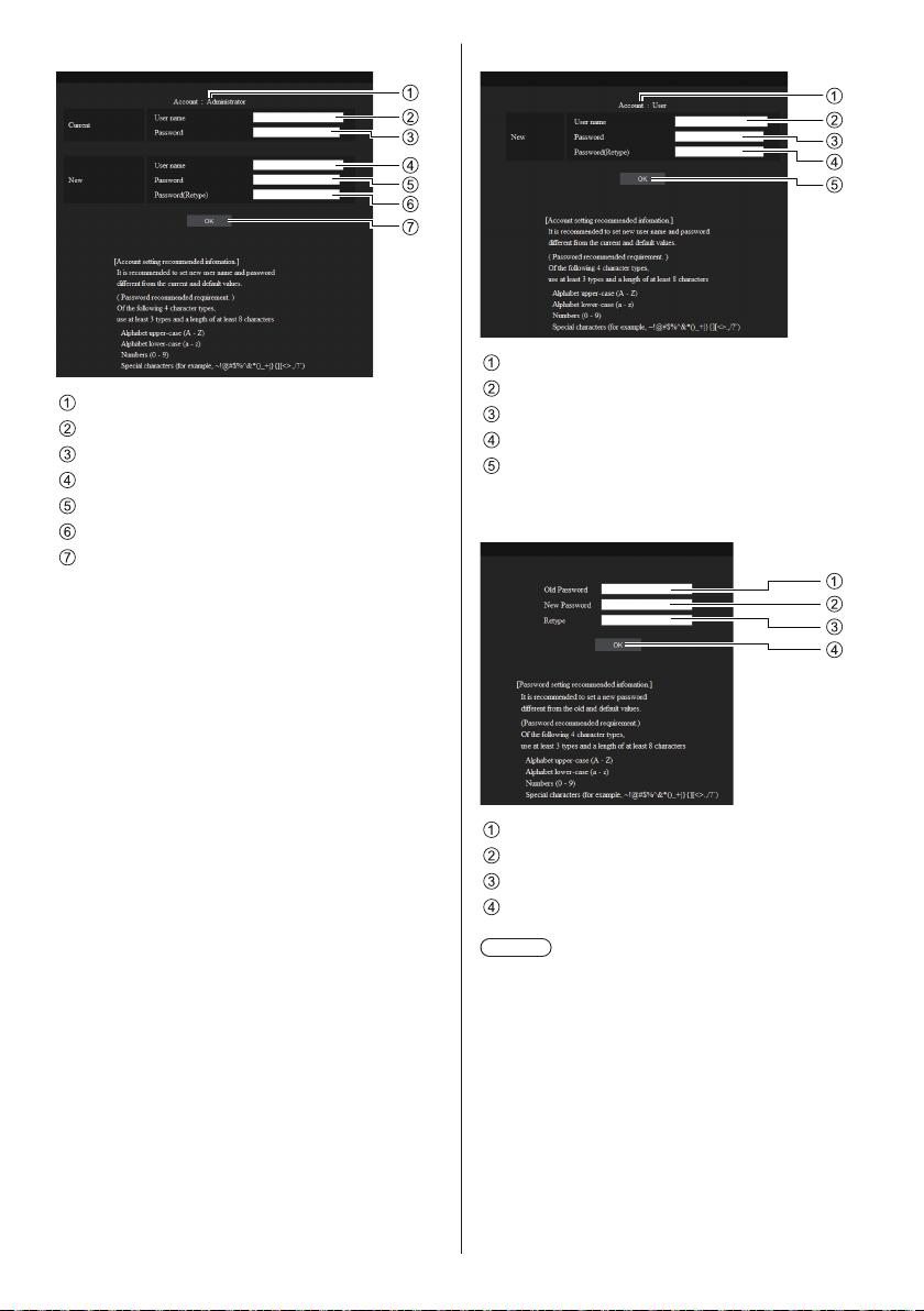
■ Administrator mode
1
2
3
4
5
6
7
1
2
3
4
5
1
2
3
4
Account
Current user name input field
Current password input field
New user name input field
New password input field
New password input field (re-enter for confirmation)
Button for executing password change
■ User account
Account
New user name input field
New password input field
New password input field (re-enter for confirmation)
Button for executing password change
■ Password change (user rights)
A user can change password only.
88
English
Current password input field
New password input field
New password input field (re-enter for confirmation)
Button for executing password change
Note
●
Alphanumeric characters can be used for a user
name.
●
Up to 16 characters can be used for a user name and
a password.
●
When changing the administrator account, both
“Current user name” and “Current password” are
required.
●
See below when you log in with administrator
privileges and change the account.
It is recommended not to use the current user
•
name/password or default values for a new user
name/password.
Page 89
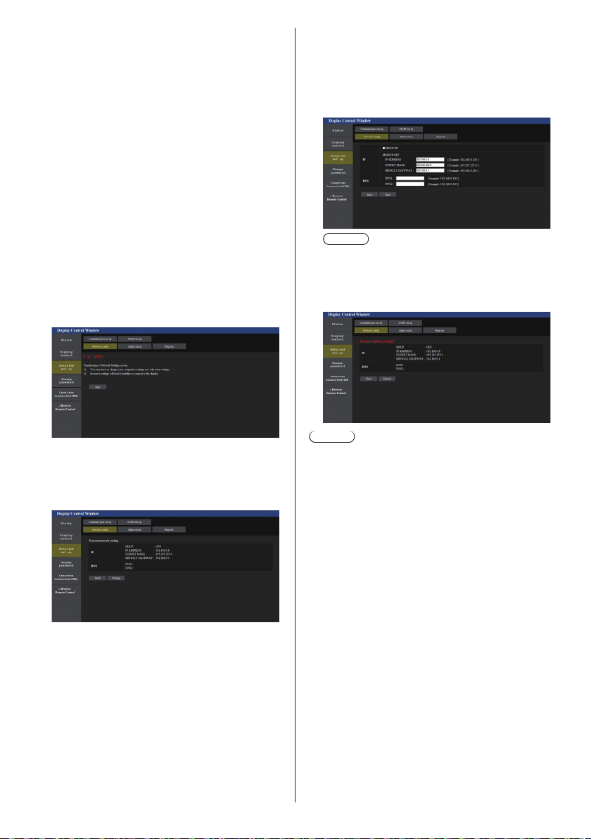
●
See below when you log in with user privileges and
change the password.
It is recommended not to use the current password
•
or default value for a new password.
●
The following are recommendations in complexity
when changing passwords. (For both administrator
privileges and user privileges)
Include at least 3 kinds of characters from the
following 4, and the number of characters should be
8 or more.
Alphabet upper case character (A to Z)
•
Alphabet lower case character (a to z)
•
Number (0 to 9)
•
Special character
•
(~ ! @ # $ % ^ & * ( ) _ + | } { [ ] < > . , / ? ', etc.)
Network config page
When connecting by logging in with administer
privileges, you can make detailed settings for network
related to display.
■ LAN settings
Click [Detailed set up] in the menu.
1
Complete the detailed settings and
3
click [Next].
In this window, DNS server settings can be made as
well as address information set on the [LAN setup]
menu of the display.
After all required items have been entered, click
[Next]. Then, a confirmation window appears.
Note
●
When [DHCP ON] is set, if the DNS server
address is acquired from the DHCP server, the
acquired address is valid.
Click [Submit].
4
The settings will be registered.
Click [Next].
2
The settings window appears, showing the current
settings.
To change the LAN settings, click [Change].
•
To return to the previous window, click [Back].
•
Note
●
Changing the setting of LAN while connected with
LAN might disconnect the connection.
English
89
Page 90
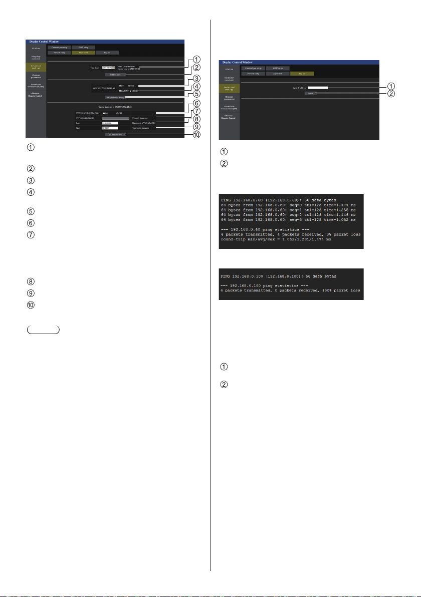
Adjust clock page
Click [Detailed set up]→[Adjust clock].
Ping test page
This page makes it possible to check whether the
network is connected to the DNS server, etc.
Click [Detailed set up]→[Ping test].
Time zone selection field
(Japan: GMT + 09:00)
Time zone setting refresh button
Display synchronization selection field
Parent/Child selection field for display
synchronization
Display synchronization setting refresh button
NTP synchronization selection field
NTP server input field
(When setting date and time with NTP
synchronization, enter the IP address or server
name. To enter the server name, setting the DNS
server is required.)
Date entry field
Time entry field
NTP synchronization setting and date setting refresh
button
Note
●
Date and time is displayed as [- -] when they are
not set.
●
When [Network control] is set to [On] and it is in
standby mode, date and time display will be blank
and they cannot be set. [Time zone], [Synchronize
display] and [NTP synchronization] cannot be set
as well.
●
When [SYNCHRONIZE DISPLAY] is set to
[ON] / [CHILD], it is not possible to set [NTP
SYNCHRONIZATION], [Date] or [Time].
●
When [NTP SYNCHRONIZATION] is set to [ON] , it
is not possible to set [Date] or [Time].
●
If the time becomes incorrect immediately after
setting the correct time, contact the dealer where
you bought the Display.
●
[NTP synchronization] operates only in power-on
state or in schedule standby state.
Enter the IP address of the server to be tested.
Button for conducting the test
Display which appears when the connection was
successful.
Display which appears when the connection failed.
Command port set up page
Set the port number to be used with command control.
Click [Detailed set up]→[Command port set up].
Input the port number to be used with command
control.
Setting update button.
90
English
Page 91
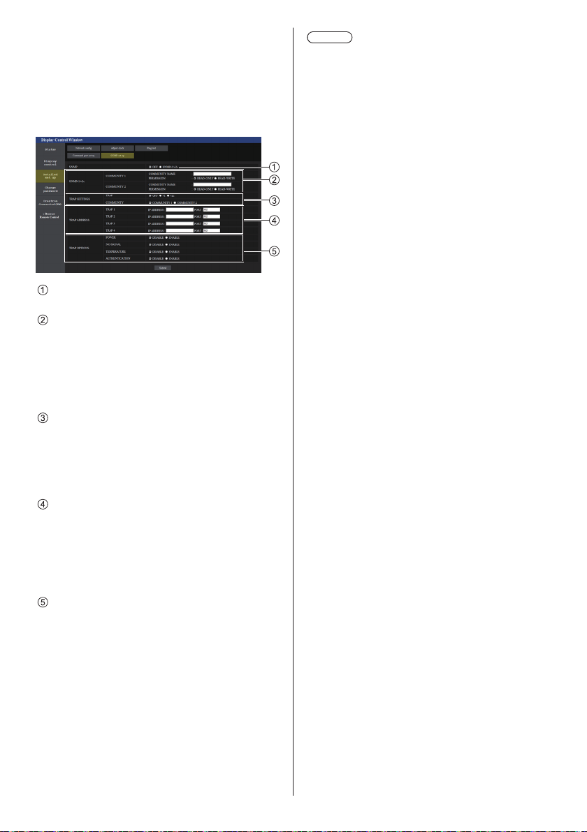
SNMP set up
Sets the various items for SNMP.
SNMP (Simple Network Management Protocol) is a
protocol to manage devices connected to the network.
If the SNMP manager is used for connection, the
information of the target device can be obtained, and its
settings can be changed.
Click [Detailed set up]→[SNMP set up].
[SNMP]:
Select the SNMP version to use.
[SNMP v1/v2c] [COMMUNITY]
[COMMUNITY NAME]:
Enter the community name of SNMP v1/v2c.
[PERMISSION]:
Select whether to obtain only information via SNMP
v1/v2c or to both obtain information and make the
setting.
[TRAP SETTINGS]
[TRAP]:
Select the SNMP version to use when sending
TRAP.
[COMMUNITY]:
Select COMMUNITY to use when sending TRAP.
[TRAP ADDRESS]
[ADDRESS]:
Set the IP address of the SNMP manager that gives
notice of TRAP.
[PORT]:
Set the TRAP reception port number of the SNMP
manager that gives notice of TRAP.
[TRAP OPTIONS]
[POWER]:
TRAP is sent if the unit enters the standby mode by
“Power management”, [No signal power off] or [No
activity power off].
[NO SIGNAL]:
TRAP is sent if no-signal continues for 5 minutes.
[TEMPERTURE]:
TRAP is sent if the temperature error occurs.
[AUTHENTICATION]:
TRAP is sent if the SNMP authentication fails.
Note
●
The maximum number of characters that can be
used for a community name is 32 with one-byte
alphanumeric characters.
●
The SNMP manager must be operating in the
system configuration used.
●
For MIB (Management Information Base) of this unit,
see the web site below.
https://panasonic.net/cns/prodisplays
●
For the settings of the SNMP manager, consult with
the network administrator.
English
91
Page 92
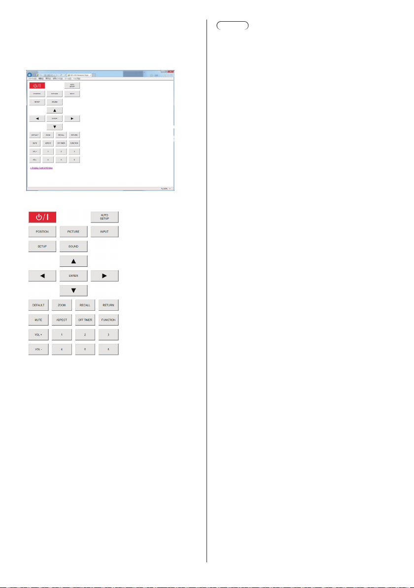
[Browser Remote Control]
It is possible to operate the display with the operation
buttons displayed on the WEB browser.
Click [Browser Remote Control].
The [Browser Remote Control] screen is displayed.
Browser Remote Control
Note
●
To use this function, set [Network control] to [On].
(see page 59)
●
The Browser Remote Control can also be displayed
by entering “http://xxx.xxx.xxx.xxx/remote/” in the
WEB browser URL entry field.
xxx.xxx.xxx.xxx is the IP address set for this
•
display.
●
The button long press operation is invalid.
●
[Options] menu (see page 67) cannot be displayed.
●
The restriction for the remote control button
operation set for [Options] - [Controller user level]
(see page 73) does not apply.
●
Avoid operating the multiple Browser Remote
Control simultaneously.
●
The same operations are applicable to both
administrator privileges and user privileges.
●
If the Browser Remote Control screen is not
displayed, consult your network administrator.
●
The screen may turn white for a moment when
updating the Browser Remote Control screen, but it
is not a malfunction.
●
While operating the Browser Remote Control, do
not operate the unit by other methods such as WEB
control screen, remote control and external control
command.
●
If the “Back” or “Forward” functions on the WEB
browser is used, the screen display may be
abnormal. In this case, the subsequent operations
are not guaranteed. Update the WEB browser.
The Browser Remote Control can be operated in the
same way as the supplied remote control.
For allocation / function of each button, see page 29.
To finish the Browser Remote Control, click
[Display Control Window] or exit the browser.
English
92
Page 93
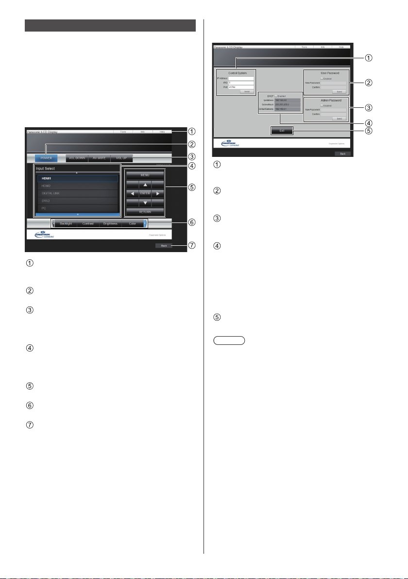
Using Web Browser Control
Crestron Connected™
(Crestron Connected™ operation screen)
You can monitor or control the Display using “Crestron
Connected™”.
If Adobe Flash Player is not installed in your computer,
or if the browser does not support Flash, this page does
not appear. In this case, return to the previous page by
clicking [Back] in the operation page.
●
Operation page
[Tools], [Info], [Help]
Switches the pages for tools, information, help using
the tab.
[POWER]
Switches between on and off of the power.
[VOL DOWN], [AV MUTE], [VOL UP]
Sets the volume, AV mute.
When the power of the Display is turned off, these
operations are not available.
[Input Select]
Sets the input selection.
When the power of the Display is turned off, this
operation is not available.
Operation buttons on the menu screen
Operates on the menu screen.
Image quality adjustments
Operate items related to image quality.
[Back]
Returns to the previous page.
●
[Tools] page
Click [Tools] on the operation page.
[Control System]
Sets the information required for the communication
with the controller that is connected to the Display.
[User Password]
Sets the password for the user rights in the
operation page of “Crestron Connected™”.
[Admin Password]
Sets the password for the administrator rights in the
operation page of “Crestron Connected™”.
[Network Status]
Displays the setting of wired LAN.
[DHCP]
•
[IpAddress]
•
[SubnetMask]
•
[DefaultGateway]
•
Displays the value in the current setting.
[Exit]
Returns to the operation page.
Note
●
When you monitor or control the Display using
“Crestron Connected™”, set [Crestron Connected™]
to [On] in the [Network settings] menu.
English
93
Page 94
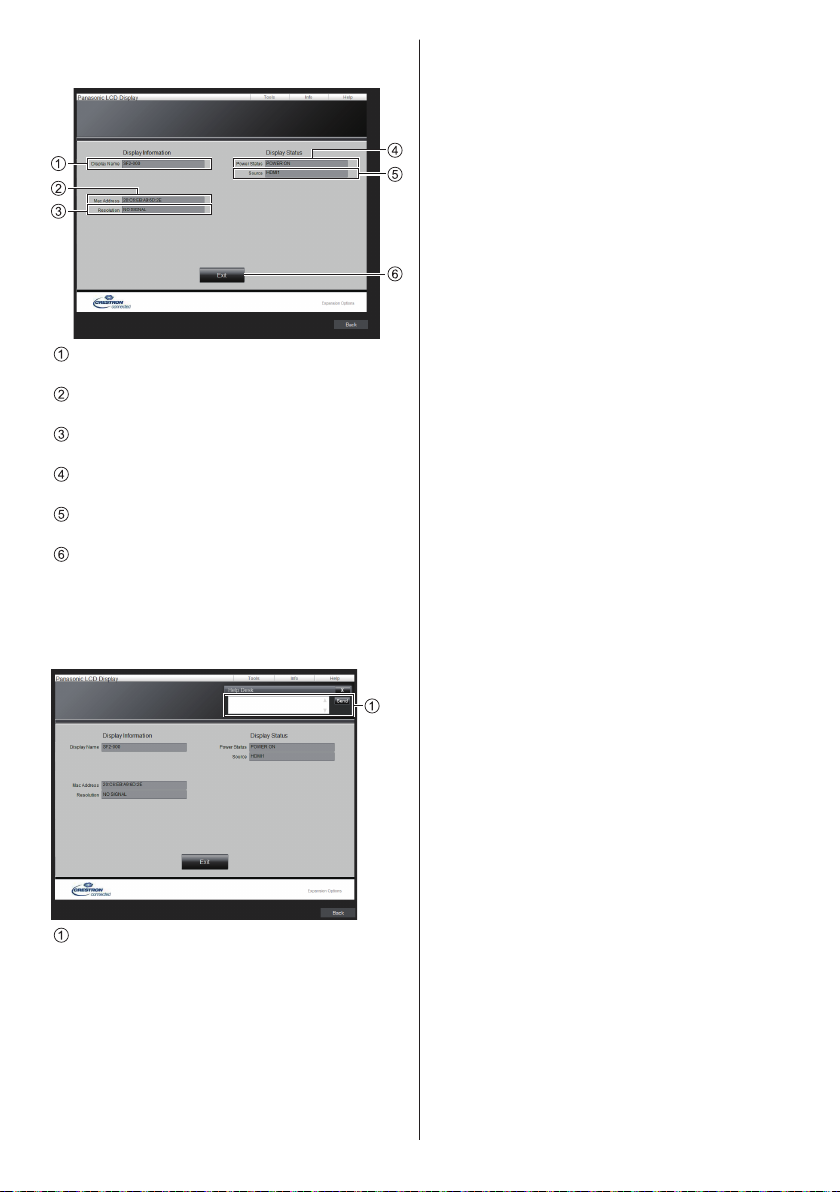
●
[Info] page
Click [Info] on the operation page.
[Display Name]
Displays the name of the Display.
[Mac Address]
Displays the MAC address.
[Resolution]
Displays the resolution of the Display.
[Power Status]
Displays the status of the power.
[Source]
Displays the selected video input.
[Exit]
Returns to the operation page.
●
[Help] page
Click [Help] on the operation page.
The [Help Desk] screen is displayed.
[Help Desk]
Sends or receives messages to the administrator
who uses “Crestron Connected™”.
English
94
Page 95
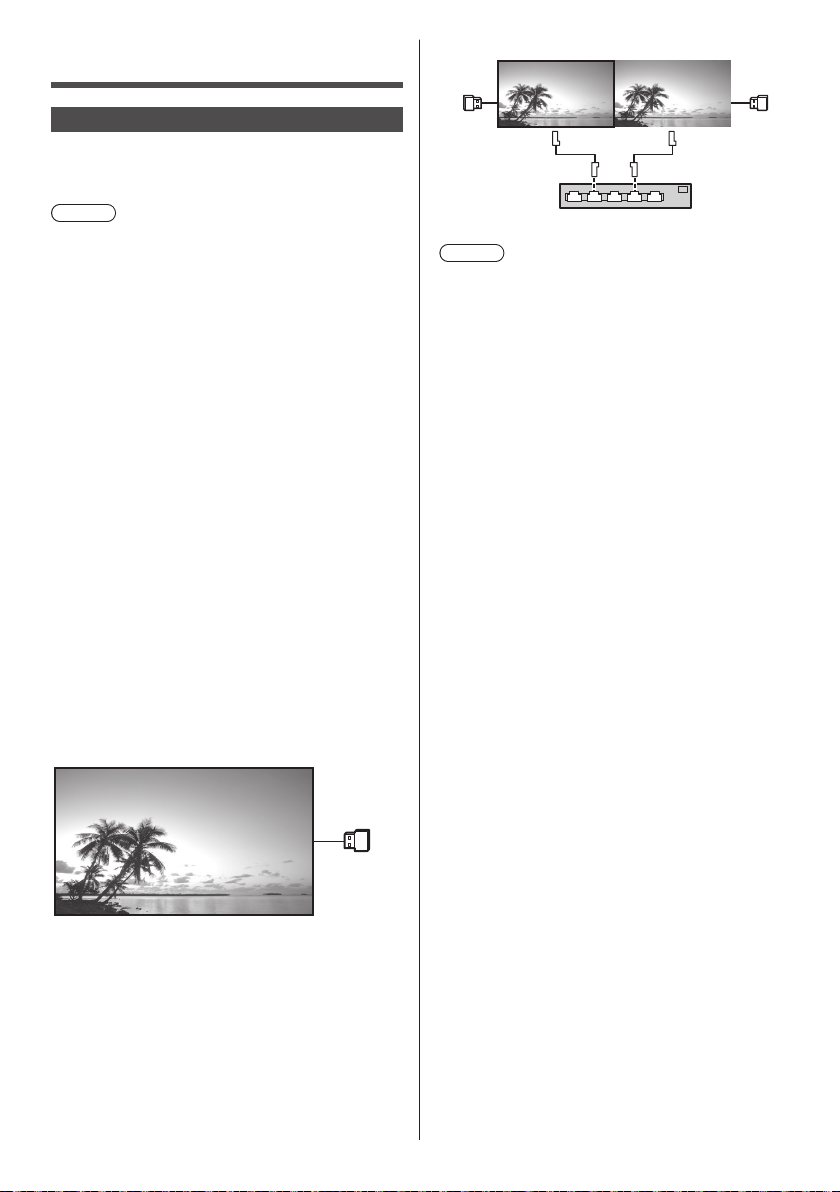
USB media player
Parent Child
Function description
The USB media player displays still pictures and
motion pictures saved in a USB memory by inserting
the USB memory device into the display unit.
Note
●
To use this function, set [USB media player] to
[Enable] in [Setup] - [USB media player settings]. (see
page 62)
●
When using the “Single Media Player”, the unit
prevents a black screen from appearing at the
switching timing of still pictures or motion pictures.
Note the following restrictions.
(1) A black screen may appear when switching a
motion picture codec.
(2) A black screen may appear or images may be
disturbed when switching to motion pictures of a
different frame rate or aspect ratio.
If an angle of view for something other than for
16:9 is used, images may be disturbed near the
end of playback.
Inserting a black screen (approx. 2 sec.) at the
switching timing for all the motion pictures can avoid
image disturbance in above (2).
([USB media player settings] (see page 62))
●
Using the content list delivery function of the Multi
Monitoring & Control Software (see page 84), content
(still/motion pictures) played back on a USB media
player and the playback list can be delivered.
(Still pictures that can be delivered are only jpg files.)
For details, refer to the manual of Multi Monitoring &
Control Software.
Single Media Player
Files are played by a single unit.
USB
memory
Hub or broadband router
Note
●
For Multi Media Player, one USB memory device is
required for one unit.
●
For Multi Media Player, the parent requires both
“scenario.dat” and “filelist.dat”, and the child requires
“filelist.dat” only.
●
Describe “GroupID:G01” without changing
characters other than numbers (2-digit description
required). Without description, the Multi Media Player
does not function.
●
When motion pictures are played on the multi media
player, a black screen may be displayed for a certain
period of time at the switching timing of motion
pictures.
memory
USB
USB
memory
Multi Media Player
Connecting more than one unit using LAN cables plays
back files in the USB memory simultaneously.
One of the multiple units becomes the parent, and the
others are children. The two-unit configuration example
is shown below.
For LAN connection, see “Network environment (Multi
Media Player only)” (see page 100).
English
95
Page 96
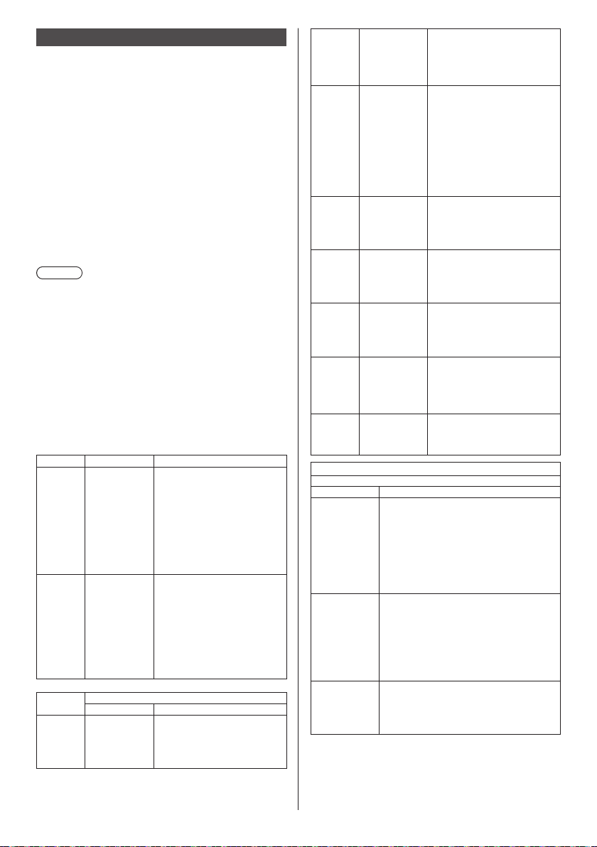
Preparation
■ Supported device
●
Commercially available USB memory devices are
supported. (Those with security functions are not
supported. Operation is not guaranteed.)
●
USB memory devices other than those formatted in
FAT16 or FAT32 cannot be used.
●
Up to 32 GB of USB memory in size are supported.
●
Only single partition configuration is supported.
■ Preparation
Prepare the following files immediately below root in
USB memory for the media player.
●
Play file
●
Scenario (as necessary)
●
File list (as necessary)
Note
●
Delete files irrelevant to playback from the USB
memory device.
●
Up to 999 files can be played back. If more than the
maximum number of files are present, some files are
not played back.
An error is displayed by the scenario file check (see
page 62).
●
Up to 999 lines of Scenario files are valid.
■ Play file
The unit’s Media Player supports the formats below.
Save immediately below root in USB memory.
Still pictures
Extension Format Limitation
jpg/
jpeg/
jpe
bmp Windows
Motion pictures
Extension Codec
avi MPEG4 AVC/
JPEG Number of pixels: Maximum
Bitmap
Video Audio
H.264
MPEG-4
Visual
4 096 x 4 096
(supports baseline only)
YUV format: supports
YUV444, YUV442 and
YUV440
Colour mode:
supports RGB only
Number of pixels: Maximum
4 096 x 4 096
(1 bit, 4 bits, 8 bits, 24 bits)
Following formats are not
supported:
Run-length encoding, bit
field, top-down, transparent
data
MPEG-1/2 Audio Layer-3
(MP3)
Linear PCM
mkv MPEG4 AVC/
H.264
MPEG-4
Visual
asf/wmv MPEG4 AVC/
H.264
MPEG-4
Visual
VC-1
Advanced
VC-1
ts/mts MPEG4 AVC/
mp4 MPEG4 AVC/
3gp MPEG4 AVC/
mov MPEG4 AVC/
flv/f4v MPEG4 AVC/
Limitation
Video
Codec
MPEG-4
AVC/
H.264
High Profile
MPEG-4
Visual
Simple
Profile and
Advanced
Simple
Profile
VC-1
Simple
Profile and
Main Profile
Simple&Main
H.264
MPEG-4
Visual
H.264
MPEG-4
Visual
H.264
MPEG-4
Visual
H.264
MPEG-4
Visual
H.264
Resolution: Maximum 1 920 x 1 080
Frame rate: Maximum 30fps
Bit rate: Maximum 30Mbps
Level 4.2 or less
•
MVC (Multi-view Video Coding)
•
unsupported
Resolution: Maximum 1 920 x 1 080
Frame rate:
Maximum 30fps (progressive)
Bit rate: Maximum 30Mbps
Only 1 warp-point GMC supported
•
Data Partitioning is not supported.
•
Resolution: Maximum 1 920 x 1 080
Frame rate: Maximum 30fps
(progressive)
Bit rate: Maximum 20Mbps
MPEG-1/2 Audio Layer-3
Linear PCM
AAC(LC)
HE-AAC(Ver.1)
MPEG-1/2 Audio Layer-3
WMA Standard
WMA9/10Pro
MPEG-1/2 Audio Layer-3
HE-AAC(Ver.1)
MPEG-1/2 Audio Layer-3
AAC(LC)
HE-AAC(Ver.1)
AAC(LC)
HE-AAC(Ver.1)
MPEG-1/2 Audio Layer-3
Linear PCM
AAC(LC)
HE-AAC(Ver.1)
MPEG-1/2 Audio Layer-3
AAC(LC)
Linear PCM
(progressive)
96
English
Page 97
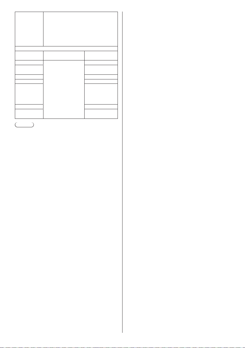
VC-1
Advanced
Profile
Audio
Codec Sampling
MP3 8/10.025/12/16/
WMA
Standard
WMA 9 32 – 384
WMA 10 Pro 32 – 384
LPCM 64 – 1 536
AAC(LC) 8 – 1 440
HE-AAC
(Ver.1)
Note
●
Maximum size per one file is 2 GB.
●
Some files may not be played back even if their
formats are supported as described here.
●
Files protected by Digital Rights Management (DRM)
cannot be played back.
●
Make sure that both audio codec and video codec
are supported. If the audio codec of motion picture
file is incompatible in format, the pictures may not be
correctly displayed. In addition, files which contain
only audio cannot be played back.
●
Playback is not possible if the maximum bit rate
specified in the codec Profile or Level is exceeded.
Also, depending on the USB memory device,
playback may be impossible even if the bit rate is less
than the indicated maximum bit rate.
●
A part of information of still pictures/motion pictures
can be confirmed on the computer accessible to the
target files.
●
If the number of pixels of a file exceeds the screen
size, the picture quality will change.
●
Example of an operation
(Windows)
1. Right-click the file, and then click [Properties].
2. Click the [Details] tab.
(Macintosh)
1. Control-click the file, and then click [Get Info].
2. Click [Details].
Resolution: Maximum 1 920 x 1 080
Frame rate:
Maximum 24fps (progressive),
30fps (interlace)
Bit rate: Maximum 30Mbps
Level: L3 or less supported
•
frequency (kHz)
22.05/24/32/44.1/
48
Bit rate (kbps)
8 – 320
32 – 384
Supported
quantization bit:
8/16/24/32
8 – 256
■ File list
It is a list of play files.
Save under the name (one-byte alphabetical characters)
“filelist.dat” immediately below root in USB memory.
●
Save files as UTF-8N format.
■ Scenario- / File list-associated terms
File name
It is the name of a play file.
A file name needs to include its extension.
Example:
Introduction.jpg
Contents_Video01.wmv
●
Enter the extension of a file name using one-byte
alphanumeric characters.
File definition
It is a file definition that is shared among scenarios and
files.
PHOTO_xxx: still image file definition
VIDEO_xxx: moving image file definition
●
The “xxx” portion can be set from 001 to 999.
●
Enter a file definition using one-byte alphanumeric
characters.
Play time
It is the play time of a file.
Play time can be specified from 3 seconds to 24 hours.
(Unit: second)
Example:
10: 10 seconds
86400: 24 hours
10.5: 10.5 seconds
It can be set down to one-tenth (1/10) of a
second using a decimal point (full stop).
Play time is omissible.
For still images, a file will be played for the period of time
that you selected in [USB media player settings] - [Slide
show duration]. (see page 62)
For moving images: a file will be played for the duration
of the play time of the file.
●
Enter play time using one-byte numeric characters.
●
When playing back large sized files, if you set the
playing back duration short, it may not be played back
properly, for example, noise appears on the screen.
In that case, set the playing back duration longer (10
seconds or longer).
■ Scenario
The play order and time can be specified for a play file.
Save under the name (one-byte alphabetical characters)
“scenario.dat” immediately below root in USB memory.
●
Save files as UTF-8N format.
●
1 to 999 lines can be specified for Scenario.
English
97
Page 98
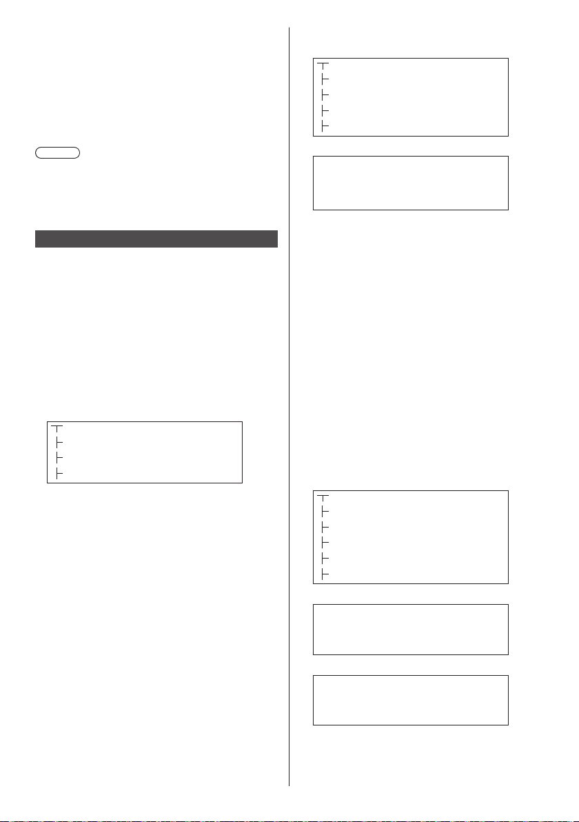
Group ID (for Multi Media Player)
It is an ID used for grouping on a network during Multi
Media Player conditions.
GroupID:Gxx : Group xx
●
The “xx” portion can be set from 01 to 10.
●
Enter a group ID using one-byte alphanumeric
characters.
Note
●
“UTF-8N”: UTF-8 encoding without BOM. Notepad for
windows doesn’t support this encoding.
Please use another editor supported UTF-8 encoding
without BOM.
Playing back the files
■ Example of setting in each mode
Single Media Player (Type 1)
Files will be played in the order in which their names
appear in USB memory.
Scenario and file list
Scenario:
Unnecessary
File list:
Unnecessary
Setting example
USB memory contents
000_Introduction.jpg
001_Contents_Video1.wmv
002_Contents_Video2.wmv
003_Contents_Video3.wmv
Play contents
For the above setting example, the following contents
will be played on repeat (loop).
1. 000_Introduction.jpg (*1)
2. 001_Contents_Video1.wmv (*2)
3. 002_Contents_Video2.wmv (*2)
4. 003_Contents_Video3.wmv (*2)
1: Played for the duration set in [Slide show
*
duration].
2: Played for the duration of the play time of the file.
*
Single Media Player (Type 2)
Files will be played in the order they were listed in a
scenario.
Scenario and file list
Scenario:
Enter [File name: Play time].
File list:
Unnecessary
Setting example
USB memory contents
scenario.dat
Introduction.jpg
Contents_Video1.wmv
Contents_Video2.wmv
Contents_Video3.wmv
scenario.dat (scenario)
Introduction.jpg:10
Contents_Video1.wmv:10
Contents_Video2.wmv:20
Contents_Video3.wmv:
Play contents
For the above setting example, the following contents
will be played on repeat (loop).
1. Introduction.jpg (10 seconds)
2. Contents_Video1.wmv (10 seconds)
3. Contents_Video2.wmv (20 seconds)
4. Contents_Video3.wmv (Played for the
Single Media Player (Type 3)
Files will be played in the order they were listed in a
scenario.
Scenario and file list
Scenario:
Enter [File definition: Play time].
File list:
Enter [File definition: File name].
Setting example
USB memory contents
filelist.dat
scenario.dat
Introduction.jpg
Contents_Video1.wmv
Contents_Video2.wmv
Contents_Video3.wmv
scenario.dat (scenario)
PHOTO_001:10
VIDEO_001:10
VIDEO_002:20
VIDEO_003:
filelist.dat (file list)
PHOTO_001:Introduction.jpg
VIDEO_001:Contents_Video1.wmv
VIDEO_002:Contents_Video2.wmv
VIDEO_003:Contents_Video3.wmv
duration of the play
time of the file)
98
English
Page 99
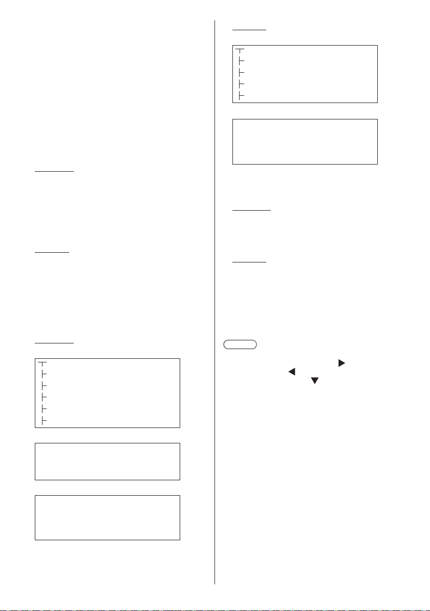
Play contents
For the above setting example, the following contents
will be played on repeat (loop).
1. Introduction.jpg (10 seconds)
2. Contents_Video1.wmv (10 seconds)
3. Contents_Video2.wmv (20 seconds)
4. Contents_Video3.wmv (Played for the
Multi Media Player
Files will be played in the order they were listed in the
scenario for Parent.
Scenario and file list
Parent side
Scenario:
Enter [File definition: Play time].
File list - The first line:
Enter [Group ID].
File list - The second and subsequent lines:
Enter [File definition: File name].
Child side
Scenario:
Unnecessary
File list - The first line:
Enter [Group ID].
File list - The second and subsequent lines:
Enter [File definition: File name].
Setting example
Parent side
USB memory contents
filelist.dat
scenario.dat
L_Introduction.jpg
L_Contents_Video1.wmv
L_Contents_Video2.wmv
L_Contents_Video3.wmv
scenario.dat (scenario)
PHOTO_001:10
VIDEO_001:10
VIDEO_002:20
VIDEO_003:
filelist.dat (file list)
GroupID:G01
PHOTO_001:L_Introduction.jpg
VIDEO_001:L_Contents_Video1.wmv
VIDEO_002:L_Contents_Video2.wmv
VIDEO_003:L_Contents_Video3.wmv
duration of the play
time of the file)
Child side
USB memory contents
filelist.dat
R_Introduction.jpg
R_Contents_Video1.wmv
R_Contents_Video2.wmv
R_Contents_Video3.wmv
filelist.dat (file list)
GroupID:G01
PHOTO_001:R_Introduction.jpg
VIDEO_001:R_Contents_Video1.wmv
VIDEO_002:R_Contents_Video2.wmv
VIDEO_003:R_Contents_Video3.wmv
Play contents
For the above setting example, the following contents
will be played on repeat (loop).
Parent side
1. L_Introduction.jpg (10 seconds)
2. L_Contents_Video1.wmv (10 seconds)
3. L_Contents_Video2.wmv (20 seconds)
4. L_Contents_Video3.wmv (*1)
Child side
1. R_Introduction.jpg (10 seconds)
2. R_Contents_Video1.wmv (10 seconds)
3. R_Contents_Video2.wmv (20 seconds)
4. R_Contents_Video3.wmv (*1)
1: Played for the duration of the play time of L_
*
Contents_Video3.wmv (Parent side).
Note
●
While the menu screen is not displayed, you can
skip to the next playback file with
playback file with , or play back again from the
beginning of the file with (Remote control operation
only).
When this operation is performed, a black screen is
inserted before playback.
●
If the date and time are changed by the [Date and
time] (see page 57) setting, the playback of the file
currently being played is stopped, and the playback
will be performed again from the beginning of the file.
, to the previous
English
99
Page 100
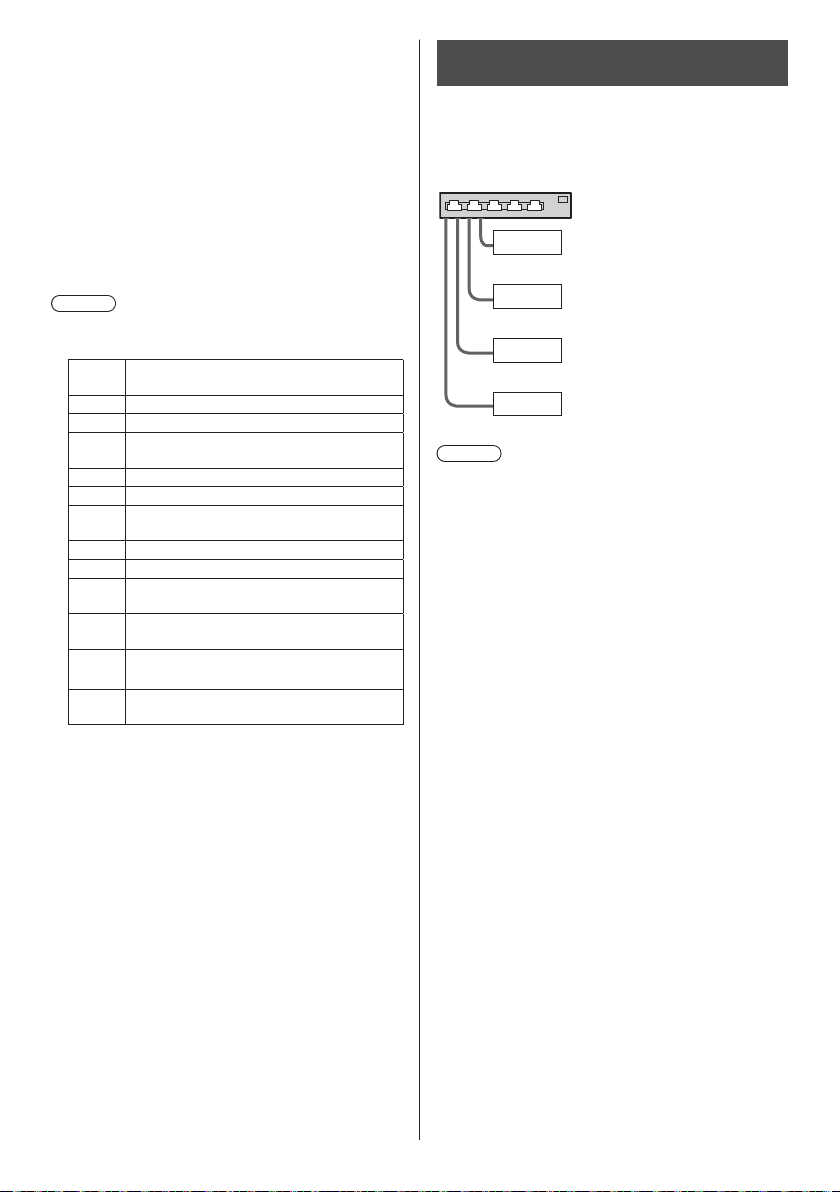
■ USB memory contents check
You can run a USB memory contents check in [USB
media player settings] - [Scenario file check]. (see page
62)
If an error is present, the information is given with the
following details.
A(B): C
D
A: Name of the file with an error
B: Row with an error
C: Error code
D: Detail of the error
Note
●
Shows leading error codes.
Details of the detected errors are as follows.
Error
code
1. No USB memory is inserted.
2. scenario.dat/filelist.dat cannot be opened.
There is an error in the contents of
3.
scenario.dat/filelist.dat.
4. The play file format is not supported.
5. No play file exists.
The necessary group ID for Multi Media
6.
Player has not been specified.
7. There are several identical file definitions.
8. The scenario's play time is over the limit.
The file definition listed in the scenario is
9.
not in the file list.
The scenario contains 0 or over 1000 play
10.
files.
There are 0 or over 1000 play files.
11.
(Single Media Player (Type 1) only)
Only the group ID is listed on the file list.
12.
(Multi Media Player only)
For error code 1 and 11, only the error code and
•
the detail of the error are displayed as shown
below.
1
No USB memory is inserted.
Supplementary note
The USB memory contents check does not determine
whether or not a play file is playable.
If a file cannot be played while Media Player is active,
an error message will be displayed.
When performing the synchronized playback on the
Multi Media Player, check in the menu [USB media
player settings] - [Scenario file check] that the file is
playable.
Detail of the error
Network environment (Multi Media Player only)
■ Example of setting up LAN connection and
IP address / Subnet mask
As mentioned below, connect several units together with
LAN cables and set up IP addresses / Subnet masks so
that all the displays exist on the same network.
Parent
Child
Child
Child
Note
●
Set [Network control] of all displays to [On]. (see page
59)
●
Depending on the network environment,
synchronization may be largely lost.
●
Do not connect other devices to prevent network
traffic jam.
●
With a router put in between the displays, you cannot
set up connection. Use them within the same subnet.
●
Do not use wireless LAN for connection since
playback may not be performed normally.
IP address:
Subnet mask:
IP address:
Subnet mask:
IP address:
Subnet mask:
IP address:
Subnet mask:
192.168.10.1
255.255.255.0
192.168.10.2
255.255.255.0
192.168.10.3
255.255.255.0
192.168.10.4
255.255.255.0
100
English
 Loading...