

Page 1
ORDER NO. VED1505558CE
取扱説明書
フルハイビジョン液晶ディスプレイ 業務用
品番
TH-65LFE8J
(65V 型 )
TH-55LFE8J
(55V 型 )
TH-48LFE8J
(48V 型 )
TH-43LFE8J
(43V 型 )
FULL HD LCD Display
Model No. TH-65LFE8U
TH-65LFE8W
TH-65LFE8E
This service information is designed for experienced repair technicians only and is not designed for use by the general public.
It dose not contain warnings or cautions to advise non-technical individuals of potential dangers in attempting to service a product.
Products powered by electricity should be serviced or repaired only by experienced professional technicians. Any attempt to service or repair the product or products dealt with in this service information by anyone else could result in serious injury or death.
There are special components used in this equipment which are important for safety. These parts are marked by 7 in the schematic
diagram, circuit board diagrams, exploded views and replacement parts list. It is essential that these critical parts should be replaced
with manufacturer’s specied parts to prevent shock, re, or other hazards. Do not modify the original design without permission of
manufacturer.
IMPORTANT SAFETY NOTICE
WARNING
© Panasonic Corporation 2015. Unauthorized
copying and distribution is a violation of law.
Rev.-4(2016-06)
Page 2

PREFACE
Table of Contents
1. Safety Precautions
2. Warning
3. Specifications
SECTION 1 SERVICE INFORMATION
1. Name of each part
2. Notes on Service
3. Service Mode
4. Troubleshooting Guide
SECTION 2 DISASSEMBLY PROCEDURES
1. Parts Locations
<65LFE8>
2. Parts Disassembly
3. Replacement of LCD Panel Module
SECTION 3 ADJUSTMENTS
1. Software Update Procedures
2. USB Cloning
3. Serial no. writing
SECTION 4 DIAGRAMS
1. Block Diagrams
SECTION 5 PARTS LIST
1. Exploded views
2. Replacement Parts List
2
Page 3
PREFACE
TH-50LFC70U/TH-50LFC70W
1 Safety Precautions
1. Safety Precautions
1.1. General Guidelines
1.1. General Guidelines
1. When conducting repairs and servicing, do not attempt to modify the equipment, its parts or its materials.
2. When wiring units (with cables, flexible cables or lead wires) are supplied as repair parts and only one wire or some of the
1.2. Touch current check (for TH-65LFE8U)
wires have been broken or disconnected, do not attempt to repair or re-wire the units. Replace the entire wiring unit instead.
3. When conducting repairs and servicing, do not twist the Fasten connectors but plug them straight in or unplug them straight
out.
4. When servicing, observe the original lead dress. If a short circuit is found, replace all parts have been overheated or damaged
by the short circuit.
5. After servicing, see to it that all the protective devices such as insulation barriers, insulation papers shields are properly
installed.
6. After servicing, make the following leakage current checks to prevent the customer from being exposed to shock hazards.
1.2. Touch-Current Check (for TH-50LFC70U)
1. Plug the AC cord directly into the AC outlet. Do not use an isolation transformer for this check.
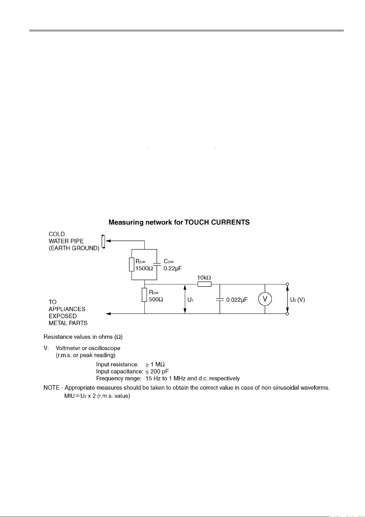
2. Connect a measuring network for touch currents between each exposed metallic part on the set and a good earth ground
such as a water pipe, as shown in Figure 1.
3. Use Leakage Current Tester (Simpson 228 or equivalent) to measure the potential across the measuring network.
4. Check each exposed metallic part, and measure the voltage at each point.
5. Reserve the AC plug in the AC outlet and repeat each of the above measure.
6. The potential at any point (TOUCH CURRENT) shall not exceed 0.5 MIU.
7. In case a measurement is out of the limits specified, there is a possibility of a shock hazard, and the equipment should be
repaired and rechecked before it is returned to the customer.
<65LFE8>
Figure 1
3
Page 4
PREFACE
TH-50LFC70U/TH-50LFC70W
1.2. Touch current check (for TH-65LFE8W)
1.3. Touch-Current Check (for TH-50LFC70W)
1. Plug the AC cord directly into the AC outlet. Do not use an isolation transformer for this check.
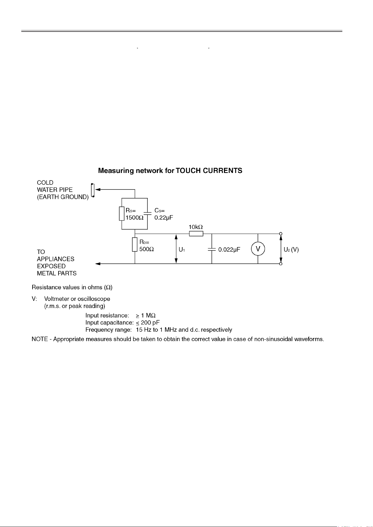
2. Connect a measuring network for touch currents between each exposed metallic part on the set and a good earth ground
such as a water pipe, as shown in Figure 1.
3. Use Leakage Current Tester (Simpson 228 or equivalent) to measure the potential across the measuring network.
4. Check each exposed metallic part, and measure the voltage at each point.
5. Reserve the AC plug in the AC outlet and repeat each of the above measure.
6. The potential at any point (TOUCH CURRENT) expressed as voltage U
For a. c.: U
For d. c.: U
Note:
The limit value of U
mA d. c.
The limit value U
7. In case a measurement is out of the limits specified, there is a possibility of a shock hazard, and the equipment should be
repaired and rechecked before it is returned to the customer.
= 35 V (peak) and U2 = 0.35 V (peak);
1
= 1.0 V,
1
= 0.35 V (peak) for a. c. and U1 = 1.0 V for d. c. correspond to the values 0.7 mA (peak) a. c. and 2.0
2
= 35 V (peak) for a. c. correspond to the value 70 mA (peak) a. c. for frequencies greater than 100 kHz.
1
and U2, does not exceed the following values:
1
<65LFE8>
Figure 1
4
Page 5

PREFACE
TH-50LFC70U/TH-50LFC70W
2 Warning
<65LFE8>
2. Warning
2.1. Prevention of Electrostatic Discharge (ESD) to Electrostatically Sensitive
2.1. Prevention of Electrostatic Discharge (ESD) to Electrostatically Sensi-
(ES) Devices
Some semiconductor (solid state) devices can be damaged easily by static electricity. Such components commonly are called Electrostatically Sensitive (ES) Devices. Examples of typical ES devices are integrated circuits and some field-effect transistors and
semiconductor “chip” components. The following techniques should be used to help reduce the incidence of component damage
caused by electrostatic discharge (ESD).
tive (ES) Devices
1. Immediately before handling any semiconductor component or semiconductor-equipped assembly, drain off any ESD on your
body by touching a known earth ground. Alternatively, obtain and wear a commercially available discharging ESD wrist strap,
which should be removed for potential shock reasons prior to applying power to the unit under test.
2. After removing an electrical assembly equipped with ES devices, place the assembly on a conductive surface such as aluminum foil, to prevent electrostatic charge buildup or exposure of the assembly.
3. Use only a grounded-tip soldering iron to solder or unsolder ES devices.
4. Use only an anti-static solder removal device. Some solder removal devices not classified as “anti-static (ESD protected)” can
generate electrical charge sufficient to damage ES devices.
5. Do not use freon-propelled chemicals. These can generate electrical charges sufficient to damage ES devices.
6. Do not remove a replacement ES device from its protective package until immediately before you are ready to install it. (Most
replacement ES devices are packaged with leads electrically shorted together by conductive foam, aluminum foil or comparable conductive material).
7. Immediately before removing the protective material from the leads of a replacement ES device, touch the protective material
to the chassis or circuit assembly into which the device will be installed.
Caution
Be sure no power is applied to the chassis or circuit, and observe all other safety precautions.
8. Minimize bodily motions when handling unpackaged replacement ES devices. (Otherwise ham less motion such as the brushing together of your clothes fabric or the lifting of your foot from a carpeted floor can generate static electricity (ESD) sufficient
to damage an ES device).
5
Page 6
PREFACE
TH-50LFC70U/TH-50LFC70W
2.2. About lead free solder (PbF)
2.2. About lead free solder (PbF)
Note: Lead is listed as (Pb) in the periodic table of elements.
In the information below, Pb will refer to Lead solder, and PbF will refer to Lead Free Solder.
The Lead Free Solder used in our manufacturing process and discussed below is (Sn+Ag+Cu).
That is Tin (Sn), Silver (Ag) and Copper (Cu) although other types are available.
This model uses Pb Free solder in it’s manufacture due to environmental conservation issues. For service and repair work, we’d
suggest the use of Pb free solder as well, although Pb solder may be used.
PCBs manufactured using lead free solder will have the PbF within a leaf Symbol PbF stamped on the back of PCB.
Caution
• Pb free solder has a higher melting point than standard solder. Typically the melting point is 50 ~ 70 °F (30~40 °C) higher. Please
use a high temperature soldering iron and set it to 700 ± 20 °F (370 ± 10 °C).
• Pb free solder will tend to splash when heated too high (about 1100 °F or 600 °C).
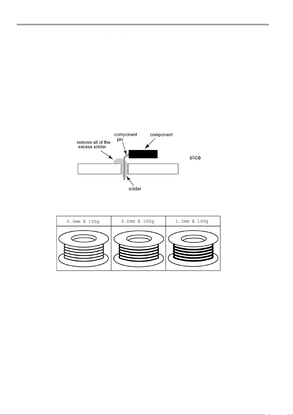
If you must use Pb solder, please completely remove all of the Pb free solder on the pins or solder area before applying Pb solder. If this is not practical, be sure to heat the Pb free solder until it melts, before applying Pb solder.
• After applying PbF solder to double layered boards, please check the component side for excess solder which may flow onto the
opposite side. (see figure below)
<65LFE8>
Suggested Pb free solder
There are several kinds of Pb free solder available for purchase. This product uses Sn+Ag+Cu (tin, silver, copper) solder. However, Sn+Cu (tin, copper), Sn+Zn+Bi (tin, zinc, bismuth) solder can also be used.
6
Page 7

PREFACE
Specifications
65-inch model
1 428 mm (W) × 803 mm (H) × 1 638 mm (diagonal) /
56.2” (W) × 31.6” (H) × 64.5” (diagonal)
(No. of pixels)
2 073 600 (1 920 (W) × 1 080 (H))
Dimensions (W × H × D)
43-inch model
969 mm × 560 mm × 61 mm /
38.2” × 22.1” × 2.4”
48-inch model
1 082 mm × 624 mm × 62 mm /
42.6” × 24.6” × 2.5”
55-inch model
1 239 mm × 712 mm × 62 mm /
48.8” × 28.0” × 2.5”
65-inch model
1 451 mm × 829 mm × 62 mm /
57.2” × 32.7” × 2.5”
Mass
43-inch model
approx. 8.7 kg / 19.2 lbs net
48-inch model
approx. 11.5 kg / 25.4 lbs net
55-inch model
approx. 16.0 kg / 35.3 lbs net
65-inch model
approx. 36.2 kg / 79.9 lbs net
Power source
TH-43/48/55/65LFE8U:
110 - 127 V AC, 50/60 Hz
TH-43/48/55/65LFE8E:
220 - 240 V AC, 50/60 Hz
Operating condition
Temperature
0 °C to 40 °C (32 °F to 104 °F)
*
1
Humidity
20 % to 80 % (no condensation)
3. Specifications
<65LFE8>
Model No.
43-inch model : TH-43LFE8U
48-inch model : TH-48LFE8U
55-inch model : TH-55LFE8U
65-inch model : TH-65LFE8U
43-inch model : TH-43LFE8E
48-inch model : TH-48LFE8E
55-inch model : TH-55LFE8E
65-inch model : TH-65LFE8E
Power Consumption
TH-43LFE8U: 135 W
TH-48LFE8U: 150 W
TH-55LFE8U: 170 W
TH-65LFE8U: 160 W
TH-43LFE8E: 135 W
TH-48LFE8E: 150 W
TH-55LFE8E: 170 W
TH-65LFE8E: 160 W
Power off condition
0.3 W
Stand-by condition
0.5 W
LCD Display panel
43-inch model
43-inch VA panel (LED backlight), 16:9 aspect ratio
48-inch model
48-inch VA panel (LED backlight), 16:9 aspect ratio
55-inch model
55-inch IPS panel (LED backlight), 16:9 aspect ratio
65-inch model
65-inch VA panel (LED backlight), 16:9 aspect ratio
Screen size
43-inch model
940 mm (W) × 529 mm (H) × 1 079 mm (diagonal) /
37.0” (W) × 20.8” (H) × 42.5” (diagonal)
48-inch model
1 054 mm (W) × 592 mm (H) × 1 209 mm (diagonal) /
41.4” (W) × 23.3” (H) × 47.6” (diagonal)
55-inch model
1 209 mm (W) × 680 mm (H) × 1 387 mm (diagonal) /
47.6” (W) × 26.7” (H) × 54.6” (diagonal)
65-inch model
1 428 mm (W) × 803 mm (H) × 1 638 mm (diagonal) /
56.2” (W) × 31.6” (H) × 64.5” (diagonal)
(No. of pixels)
2 073 600 (1 920 (W) × 1 080 (H))
Dimensions (W × H × D)
43-inch model
969 mm × 560 mm × 61 mm /
38.2” × 22.1” × 2.4”
48-inch model
1 082 mm × 624 mm × 62 mm /
42.6” × 24.6” × 2.5”
55-inch model
1 239 mm × 712 mm × 62 mm /
48.8” × 28.0” × 2.5”
65-inch model
1 451 mm × 829 mm × 62 mm /
57.2” × 32.7” × 2.5”
Mass
43-inch model
approx. 8.7 kg / 19.2 lbs net
48-inch model
approx. 11.5 kg / 25.4 lbs net
55-inch model
approx. 16.0 kg / 35.3 lbs net
65-inch model
approx. 36.2 kg / 79.9 lbs net
Power source
TH-43/48/55/65LFE8U:
110 - 127 V AC, 50/60 Hz
TH-43/48/55/65LFE8E:
220 - 240 V AC, 50/60 Hz
Operating condition
Temperature
0 °C to 40 °C (32 °F to 104 °F)
Humidity
20 % to 80 % (no condensation)
1
*
7
Page 8
PREFACE
<65LFE8>
Storing condition
Temperature
-20 °C to 60 °C (-4 °F to 140 °F)
Humidity
20 % to 80 % (no condensation)
Connection terminals
HDMI 1
HDMI 2
2
TYPE A Connector ×
Audio signal:
Linear PCM (sampling frequencies - 48 kHz,
44.1 kHz, 32 kHz)
DVI-D IN
DVI-D 24 Pin:
Compliance with DVI Revision 1.0
Content Protection:
Compatible with HDCP 1.1
PC IN
High-Density Mini D-sub 15 Pin:
Compatible with DDC2B
Y/G:
1.0 Vp-p (75 Ω) (with sync)
0.7 Vp-p (75 Ω) (without sync)
B/CB/B:
P
0.7 Vp-p (75 Ω)
R/CR/R:
P
0.7 Vp-p (75 Ω)
HD/VD:
1.0 - 5.0 Vp-p (high impedance)
VIDEO
Audio/Video 4-pole mini jack (M3) (see page 19)
Video: 1.0 Vp-p (75 Ω)
Audio: 0.5 Vrms
*
2
LAN
For RJ45 network connections,
compatible with PJLink
Communication method:
RJ45 10BASE-T/100BASE-TX
IR IN
Mini jack (M3)
IR OUT
Mini jack (M3)
USB
TYPE A USB connector
5V DC / 1A (USB 3.0 is not supported.)
Sound
Speakers
43/48/55-inch models:
80 mm × 30 mm × 2 pcs
65-inch model:
96 mm × 27 mm × 2 pcs
Audio Output
20 W [10 W + 10 W] (10 % THD)
Remote Control Transmitter
Power source
3 V DC (battery (AAA/R03/UM4 type) × 2)
Operating range
Approx. 7 m (22.9 ft)
(when operated directly in front of receptor)
Mass
Approx. 63 g / 2.22 ozs (including batteries)
Dimensions (W × H × D)
44 mm × 106 mm × 20.5 mm /
1.74” × 4.18” × 0.81”
AUDIO IN
Stereo mini jack (M3) 0.5 Vrms
Shared with DVI-D IN and PC IN
AUDIO OUT
Stereo mini jack (M3) 0.5 Vrms
Output: Variable (-∞ to 0 dB)
(1 kHz 0 dB input, 10 kΩ load)
SERIAL IN
External Control Terminal
D-sub 9 Pin:
RS-232C compatible
*1: Environmental temperature to use this unit at
high altitudes (1 400m (4 593 ft) and higher and
below 2 800 m (9 186 ft) above sea level): 0 °C to
35 °C (32 °F to 95 °F)
: VIERA LINK is not supported.
*2
Note
●
Design and specifications are subject to change
without notice. Mass and dimensions shown are
approximate.
●
This equipment complies with the EMC standards
listed below.
EN55022, EN55024, EN61000-3-2, EN61000-3-3.
8
Page 9

SECTION 1 SERVICE INFORMATION
Service Information
Model No. TH-65LFE8U
TH-65LFE8W
TH-65LFE8E
CONTENTS
SECTION 1 SERVICE INFORMATION
1. Name of each part .........................................INF-2
1. 1. Display body
1. 2. Connecting terminals
1. 3. Remote controls
2. Notes on Service ..........................................INF-5
2. 1. Before service operation
2. 2. Service
3. Service Mode .............................................INF-6
3. 1. How to display CAT mode
3. 2. Settings and adjustments mode (IIC Mode)
3. 3. Software, EEPROM version and failure information (CD Mode)
3. 4. Market select setting mode (MS Mode)
3. 5. Network connection check mode (NW Mode)
3. 6. Status display mode (SD Mode)
4. Troubleshooting Guide ....................................INF-12
4. 1. Self check of signal system
4. 2. Self check of power system
4. 3. Troubleshooting ow
<65LFE8>
INF-1
Page 10
SECTION 1 SERVICE INFORMATION
<65LFE8>
1. Name of each part
1. 1. Display body
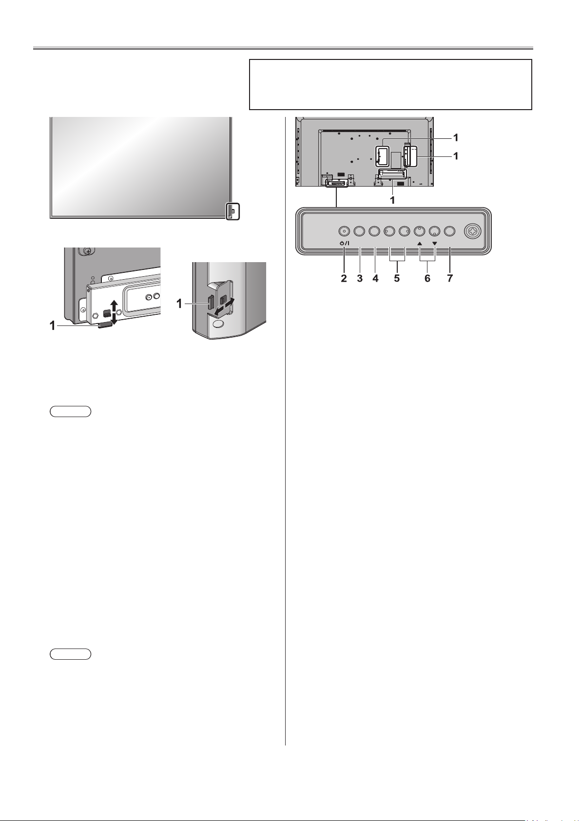
65-inch model
●
The power indicator and remote control sensor
can be taken in and out by sliding the lever on the
rear panel.
●
It is also possible to store the part by pushing it
directly.
Note
●
For normal use, pull out the power indicator and
remote control sensor from the edge side of the
main unit by operating the lever on the rear panel.
Depending on the setup condition such as when
using the multi display, store them in the main unit.
1 Power Indicator / Remote control sensor
The
Power Indicator will light.
When the power of the unit is ON (Main Power On /
Off switch: ON)
●
Picture is displayed: Green
●
Power OFF (Standby) with remote control: Red
When [Network control] is set to [On] (see page
55) : Orange (Red/Green)
●
Power OFF with “Power management” function:
Orange (Red/Green)
“Power management” function (see page 51)
When the power of the unit is OFF (Main Power On
Off switch: OFF): No light
Note
The unit will still consume some power as long as the
power cord is still inserted into the wall outlet.
When the power indicator is orange, power consumption
during standby is generally larger than that of when the
power indicator is red.
43/48/55-inch
models
Some of the pages on this section are excerpted from the owner's
manual, thus the reference page numbers on pages indicate those for
owner's manual .
MENU ENTERINPUT
1 External Input Terminal
●
Connect to video equipment, PC, etc. (see page
15)
2 <Main Power On / Off switch>
●
Turns the power On / Off.
3 <INPUT (Unit)> (INPUT signal selection)
●
Selects the connected device. (see page 27)
4 <MENU (Unit)>
●
Each time the <MENU (Unit)> button is pressed,
the menu screen will switch. (see page 36)
5 <+ (Unit)> / <- (Unit)>
●
Volume Up “+” Down “–”
●
Adjusts the volume. Also, switches the settings or
adjusts the level on the main screen. (see page
28, 36)
6 < ▲ (Unit)> / < ▼ (Unit)>
●
Selects the setting item. (see page 36)
7 <ENTER (Unit)>
●
Configures the item on menu screen. (see page
36)
●
Switches aspect mode. (see page 29)
-
+
INF-2
Page 11
SECTION 1 SERVICE INFORMATION
Video equipment connection
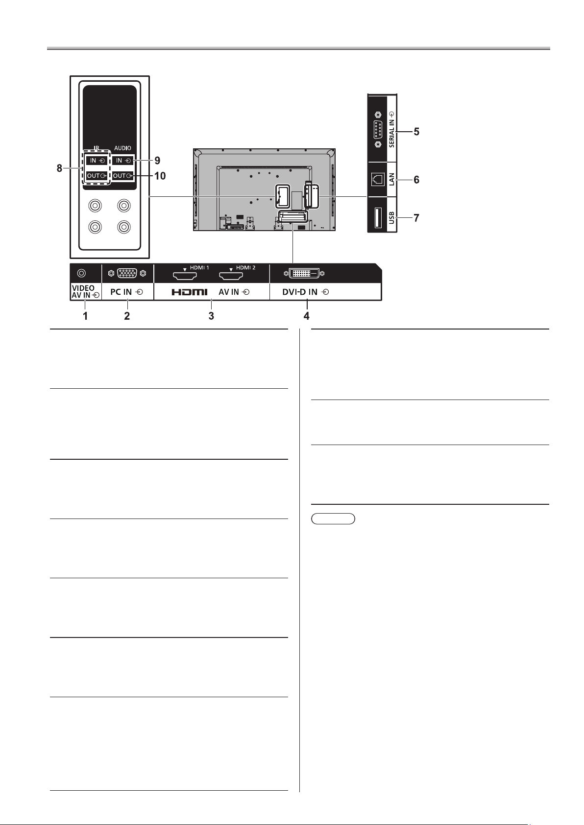
1. 2. Connecting terminals
<65LFE8>
1 AV IN (VIDEO): Composite Video Input Terminal
Connect to video equipment such as
VCR or DVD player, etc.
(see page 19)
2 PC IN: PC Input Terminal
Connect to video terminal of PC,
video equipment with “Y, P
P
R(CR)” or “R, G, B” output.
(see page 18)
3 AV IN
(HDMI 1,
HDMI 2):
4 DVI-D IN: DVI-D Input Terminal
5 SERIAL IN: Serial Control Terminal
HDMI Input Terminal
Connect to video equipment such as
VCR or DVD player, etc.
(see page 16)
Connect to video equipment with
DVI-D output.
(see page 17)
Control the Display by connecting
to PC.
(see page 19)
B(CB),
8 IR IN, IR OUT: Infrared Signal Input/output
Terminal
Use this when operating more than
one display with one remote control.
(see page 21)
9 AUDIO IN: Audio input terminal shared with
DVI-D IN and PC IN
(see page 17,18)
10 AUDIO OUT: Analogue Audio Output Terminal
Connect to audio equipment with
analogue audio input terminal.
(see page 21)
Note
●
If the outer shape of the plug of a connection cable
is large, it may come in contact with the plug of an
adjacent connection cable. Use a connection cable
with the suitable plug size for the terminal alignment.
6 LAN: LAN Terminal
Control the Display by connecting to
Network.
(see page 64)
7 USB: USB Memory Terminal
Connect the USB memory to use the
USB media player function. Also,
this can be used to supply power of
up to 5V/1A to an external device
when receiving images.
(see page 22,31)
INF-3
Page 12
SECTION 1 SERVICE INFORMATION
Used to return to the previous menu. (see page 36)
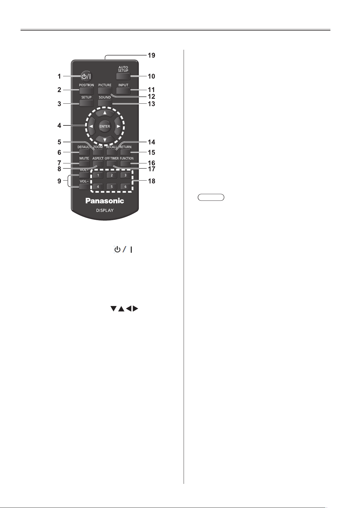
1. 3. Remote controls
1 Standby (ON/OFF) button ( )
●
Turns the power on or off when the Display is
turned on at the power switch.(see page 25)
2 POSITION
(see page 38)
3 SETUP
(see page 47)
4 ENTER / Cursor buttons (
●
Used to operate the menu screens. (see page 36)
5 ZOOM
●
Enters the digital zoom mode. (see page 30)
6 DEFAULT
●
Resets the settings of picture, sound, etc., to
defaults. (see page 38, 40, 41)
7 MUTE
●
Sound mute on / off. (see page 28)
8 ASPECT
●
Adjusts the aspect. (see page 29)
9 VOL + / VOL -
●
Adjusts sound volume level. (see page 28)
10 AUTO SETUP
●
Automatically adjusts the position/size of the
screen. (see page 38)
11 INPUT
●
Switches input to display on the screen. (see
page 27)
12 PICTURE
(see page 41)
)
<65LFE8>
13 SOUND
(see page 40)
14 RECALL
●
Displays the current setting status of Input mode,
Aspect mode, etc. (see page 27)
15 RETURN
●
16 FUNCTION
(see page 57)
17 OFF TIMER
●
Switches to stand-by after a fixed period. (see
page 28)
18 Numeric buttons (1 - 6)
●
Used as shortcut buttons by assigning frequently
used operations. (see page 57)
19 Signal emission
Note
●
In this manual, buttons of the remote control and
the unit are indicated as < >.
(Example: <INPUT>.)
The operation is mainly explained indicating the
remote control buttons but you can also operate
with the buttons on the unit when there are the
same buttons.
INF-4
Page 13
SECTION 1 SERVICE INFORMATION
<65LFE8>
2. Notes on Service
2. 1. Before service operation
2. 1. 1. LCD panel module
1. Although an LCD panel module is a product of high-precision technology, some of the pixels on the image may be missing
or constantly lit. Please note that this is not a failure.
2. Displaying a still image for a longer time may result in an after-image on the LCD panels. If this happens, display the all
white screen in the test pattern for an hour or more.
2. 2. Service
2. 2. 1. Supporting Methods
The basic service policy is shown below.
Repair contents Applied parts
Block replacement
Module replacement
Replaced by discrete components Other electrical parts and mechanism parts
- LCD panel module
- PCB module
2. 2. 2. Repair
1. Before repairing, make sure to turn off the main power and disconnect the power plug from the power outlet.
* When replacing the PCB module, the internal electrical parts can be broken by the static electricity of clothes or human
body. Please take care in static electricity, use an antistatic wrist strap or wear the anti-static electricity gloves.
2. After repairing, please check the gradation (10 step or the gray scale) test pattern or moving image.
Also, please check that it is normal on a self check screen.
2. 2. 3. Replacement of A-Module
1. When replacing A-module due to the defective, adjustment data copy to new A-module is available. Please refer to the
"USB Cloning (Adj.6-7) " in the SECTION3.
2. When A-module is replaced, the MAC address of LAN will be changed. Explain it to the customers in advance.
INF-5
Page 14
SECTION 1 SERVICE INFORMATION
3. Service Mode
3. 1. How to display CAT mode
■ To display the CAT mode
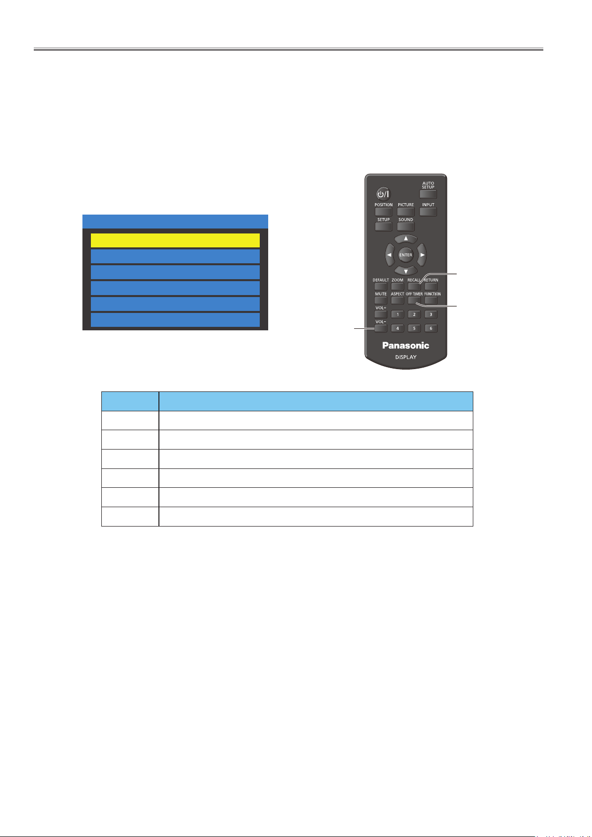
1. Press the [OFF TIMER] button to select 30, 60, or 90, not 0min.
2. Set the volume level to "0" with the [VOL-] button.
3. Press and hold the [RECALL] button for more than 3 seconds. (This must be done while the volume display is on.)
The CAT mode will appear on the screen.
CAT mode menu
CAT Panel sys.8.2
IIC Mode
CD Mode
NW Mode
SD Mode
MS Mode
ID Mode
VOL -
RECALL
OFF TIMER
<65LFE8>
Mode Function
IIC Mode Setup and adjustment
CD Mode Software, EEPROM version, Error history information display
NW Mode Network information display
SD Mode MTBF parameter (Used time, internal temperature) display
MS Mode Destination setting
ID Mode Self diagnosis status display
■ To exit the CAT mode
Turn off the Display with the main switch or remote control unit.
INF-6
Page 15
SECTION 1 SERVICE INFORMATION
<65LFE8>
3. 2. Settings and adjustments mode (IIC Mode)
1. Display the CAT mode (Refer to 3.1.).
CAT Panel sys.8.2
IIC Mode
CD Mode
NW Mode
SD Mode
MS Mode
ID Mode
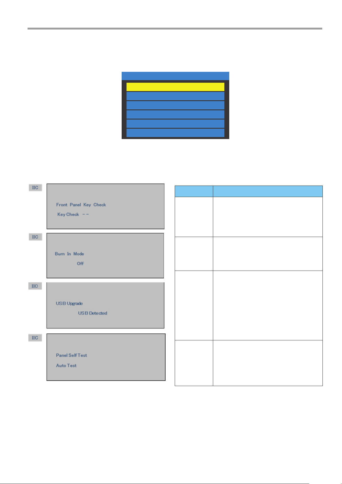
2. The CAT mode menu appears on the screen. Select the [IIC Mode] menu with [pq] buttons and press the [ENTER] button
to enter the IIC mode.
3. Press the [pq ] buttons to switch the sub mode.
4. Press the [tu] button to switch On or Off.
Sub mode Function
Displays name of the control button when each
button on the control panel is pressed.
Front panel
Key Check
Burn In Mode
USB Upgrade
Panel Self Test
It can be checked for cable disconnection or
contact failure.
After checking for all the buttons on the control
panel, the "OK" will appear.
On/Off (Default: Off)
Sets up aging mode.
When no signal input, internal test patterns (Black,
Green, Red, Blue, White) will automatically be
displayed sequentially.
Detects USB memory installed
-USB Detected : USB memory is installed
-USB Removed : USB memory is removed
Press and hold the [ENTER] button while
indicating "USB Detected", the Main MCU
rmware upgrade dialogue window will appear on
the screen. (Refer to Section 3 for the details)
When no signal input, internal test patterns (Black,
Green, Red, Blue, White) will automatically be
displayed sequentially.
Test patterns are generated in the LCD Panel.
To exit the IIC mode
Press the [RETURN] button to return to the CAT mode menu
INF-7
Page 16
SECTION 1 SERVICE INFORMATION
<65LFE8>
3. 3. Software, EEPROM version and failure information (CD Mode)
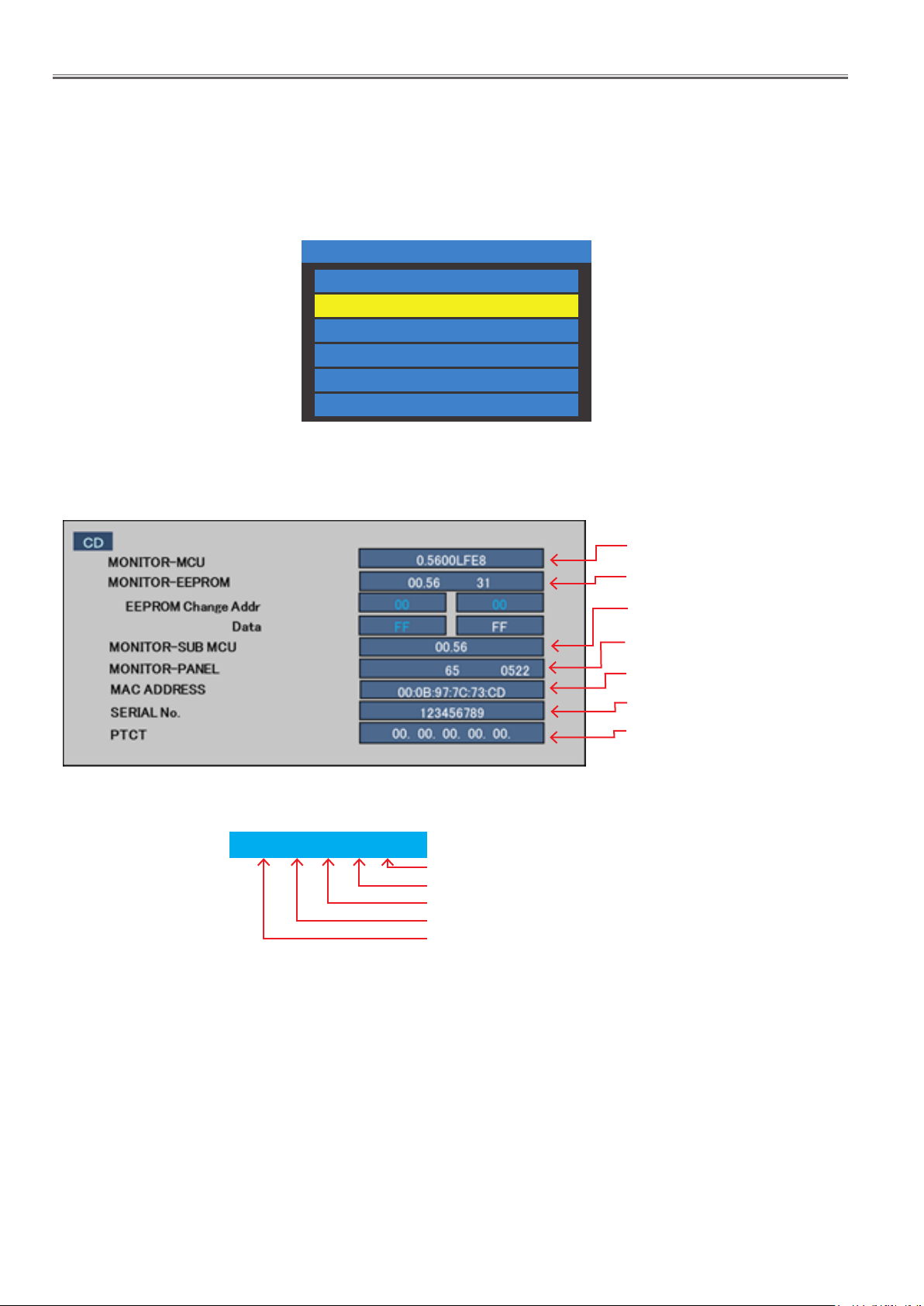
• This model provides a power failure history function (5 histories) as PTCT information in the CD mode.
• On the self check for a signal system, only one history is displayed (it will disappear after self checking). The PTCT displays
up to 5 histories and they do not disappear even if the self check has been done. You can see the history of power failure
any time.
1. Display the CAT mode (Refer to 3.1.).
CAT Panel sys.8.2
IIC Mode
CD Mode
NW Mode
SD Mode
MS Mode
ID Mode
2. The CAT mode menu appears on the screen. Select the [CD Mode] menu with [pq] buttons and press the [MUTE] button
for more than 3 seconds to enter the CD mode.
Firmware version of Main MCU
EEPROM version Destination code
Firmware version of Sub MCU
Firmware version of FRC
MAC address
Product serial number
PTCT failure history information
(Refer to the below.)
About PTCT information
01. 04. 09. 0D. 04.
First failure
Second failure
3rd latest failure
2nd latest failure
Latest failure
For further information of PTCT failure code, refer to the item [4.2. Self check of power system].
To exit the CD mode
Press the [RETURN] button to return to the CAT mode menu
INF-8
Page 17
SECTION 1 SERVICE INFORMATION
<65LFE8>
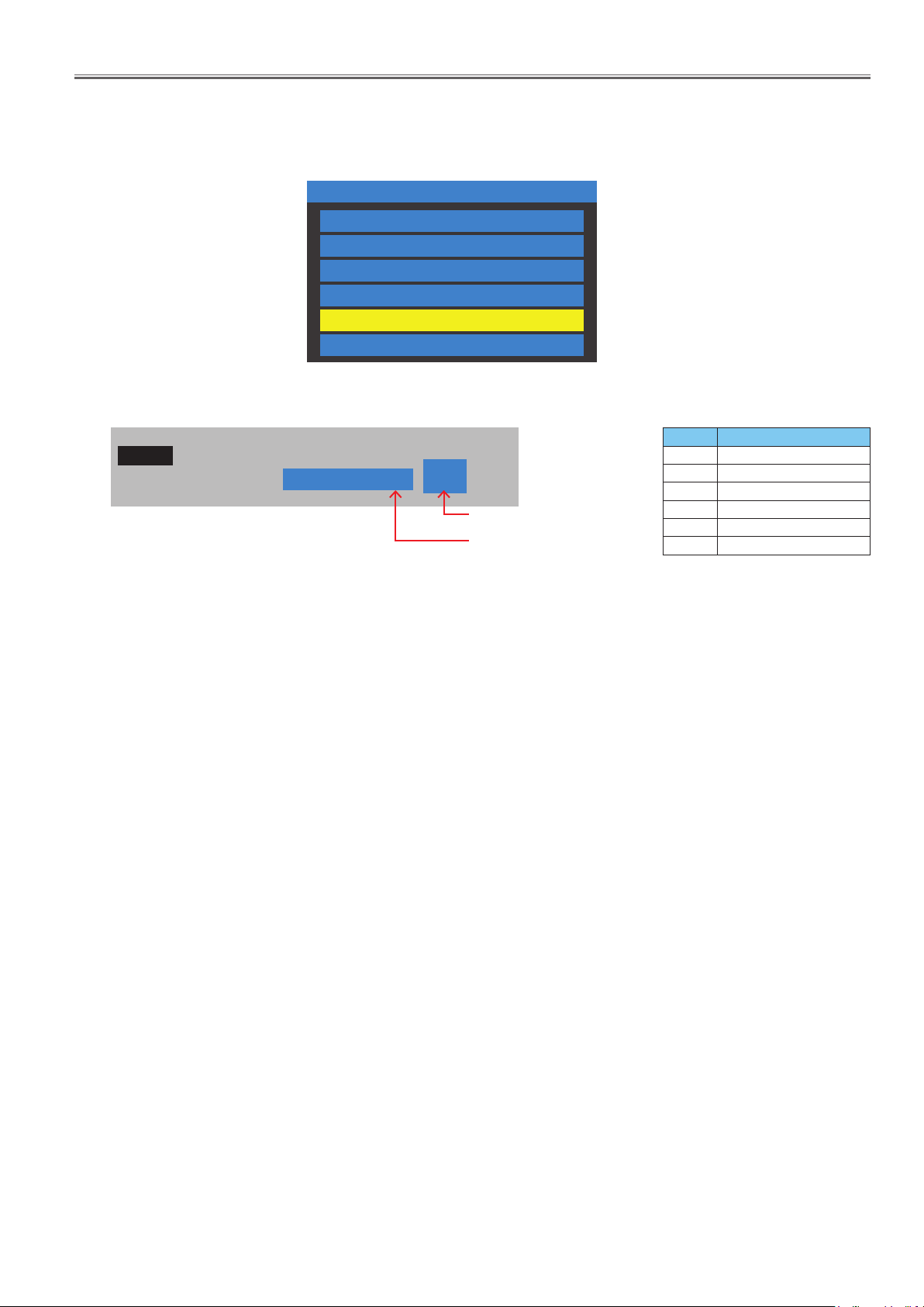
3. 4. Market select setting mode (MS Mode)
■ After replacing the A module, this market select setting must be done following to the procedure below.
1. Display the CAT mode (Refer to 3.1.).
CAT Panel sys.8.2
IIC Mode
CD Mode
NW Mode
SD Mode
MS Mode
ID Mode
2. The CAT mode menu appears on the screen. Select the [MS Mode] menu with [pq] buttons and press the [MUTE] button
for more than 3 seconds to enter the MS mode.
Number Model (Destination)
MS
Market Select 01.00 31 0
New destination number
Present destination number
0 65LFE8J (Japan)
1 65LFE8U (North A merica)
2 65LFE8E (Europe, Oceania)
3 65LFE8W (Asia, Oceania)
18 65LFE8C (China)
31 For factory use
3. Select desired destination number with [pq ] buttons and press the [ENTER] button to set. The present destination number
will be changed to the same number of new destination number. At this moment, new destination number will be applied
and all the user setting value will be reset to the factory initial data according to the destination set.
4. The message "Please turn off the power" will appear and then turn the main switch off and on again. (Note 1)
5. The Display will turn on and then the "Display Language Selection" menu will be displayed on the screen. Select your lan-
guage with the [pq ] buttons and press the [ENTER] button to set.
INF-9
Page 18
SECTION 1 SERVICE INFORMATION
<65LFE8>
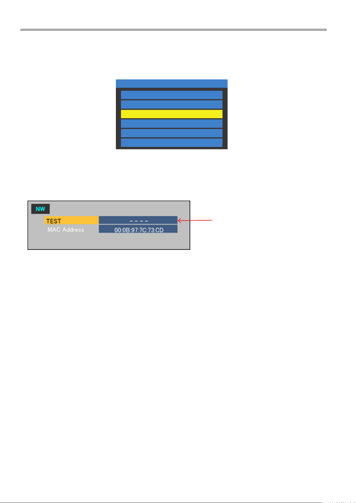
3. 5. Network connection check mode (NW Mode)
• To check the network connection, take the procedure below.
Make sure to set the "Control I/F Select" to "LAN" or “RS232C” to use this function.
1. Display the CAT mode (Refer to 3.1.).
CAT Panel sys.8.2
IIC Mode
CD Mode
NW Mode
SD Mode
MS Mode
ID Mode
2. The CAT mode menu appears on the screen. Select the [NW Mode] menu with [pq] buttons and press the [ENTER] button
to enter the NW mode.
3. Press the [ENTER] button to start the network connection check. The check result will be displayed in a few seconds.
To exit the NW mode
Press the [RETURN] button to return to the CAT mode menu
Displays the result of [TEST]
• OK : There is a response of PING
NG : Time Out
•
• BSY : On test executing
• G_NG : No response of PING
• L_NG : A LINK state is not established
INF-10
Page 19
SECTION 1 SERVICE INFORMATION
<65LFE8>
3. 6. Status display mode (SD Mode)
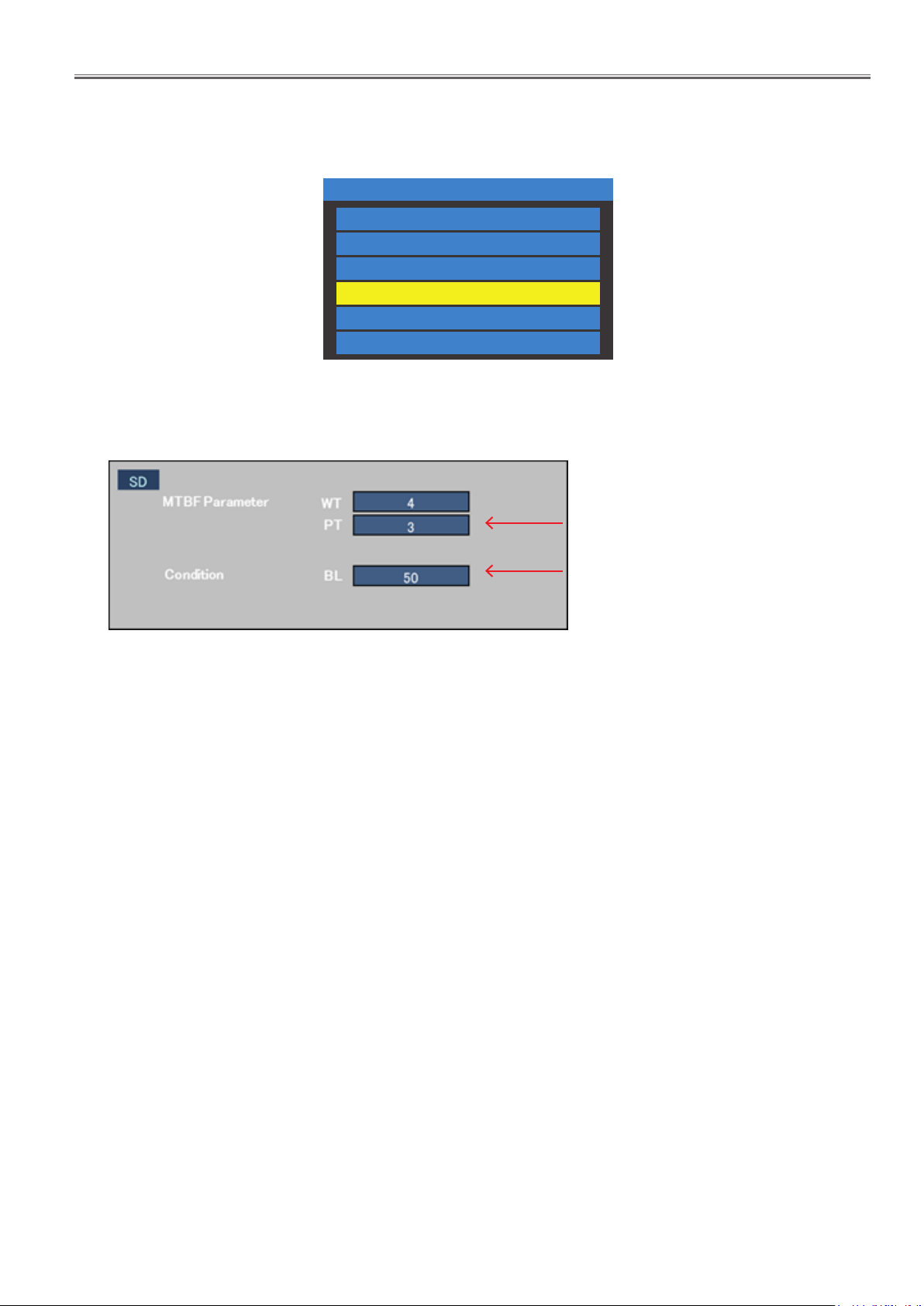
• In the SD mode, internal temperature, cumulated used time and cumulated power-on times can be checked.
1. Display the CAT mode (Refer to 3.1.).
CAT Panel sys.8.2
IIC Mode
CD Mode
NW Mode
SD Mode
MS Mode
ID Mode
2. The CAT mode menu appears on the screen. Select the [SD Mode] menu with [pq] buttons and press the [ENTER] button
to enter the SD mode.
To exit the SD mode
Press the [RETURN] button to return to the CAT mode.
Parameter
•
WT : Cumulated power-on times
PT : Cumulated used time (hour)
Condition : Internal temperature (ºC)
•
BL : Back Light setting value *
INF-11
Page 20
SECTION 1 SERVICE INFORMATION
<65LFE8>
4. Troubleshooting Guide
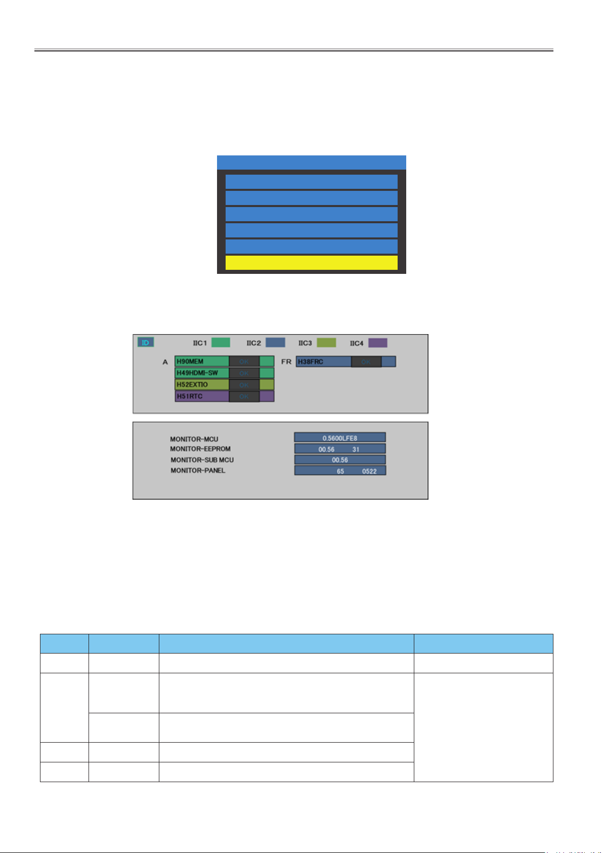
The failure symptom "Power off" or "No picture or No sound" is reported but it can not be confirmed in the service, use this
function to confirm the failure status and narrow down the failure circuit.
4. 1. Self check of signal system
1. Display the CAT mode (Refer to 3.1.).
CAT Panel sys.8.2
IIC Mode
CD Mode
NW Mode
SD Mode
MS Mode
ID Mode
2. The CAT mode menu appears on the screen. Select the [ID Mode] menu with [pq] buttons, and press and hold the
[MUTE] button until the ID mode menu appears. (It takes a few seconds to display it.)
To exit the ID mode
- Press the [RETURN] button to return to the CAT mode menu
- Turn the Display off with remote control or unit. (In case the Main MCU version is 1.00 or 1.01)
■ Treatment action
Items IIC Device Symptom Action
IIC2 H38FRC Abnormality on the picture Check or replace FRC module
Not memorized some settings below.
H90MEM
IIC1
H49HDMI-SW
IIC3 H52EXTIO Abnormality on the picture
IIC4 H 51RTC Not operate timer function
Items listed below in the SETUP menu.
(Display ID Setting/Timer Setting/Control Terminal Select)
Abnormality on the picture of Digital signal (HDMI, DVI1/DVI2,
DisplayPort, Digital Link)
INF-12
Check or replace A module
Page 21
SECTION 1 SERVICE INFORMATION
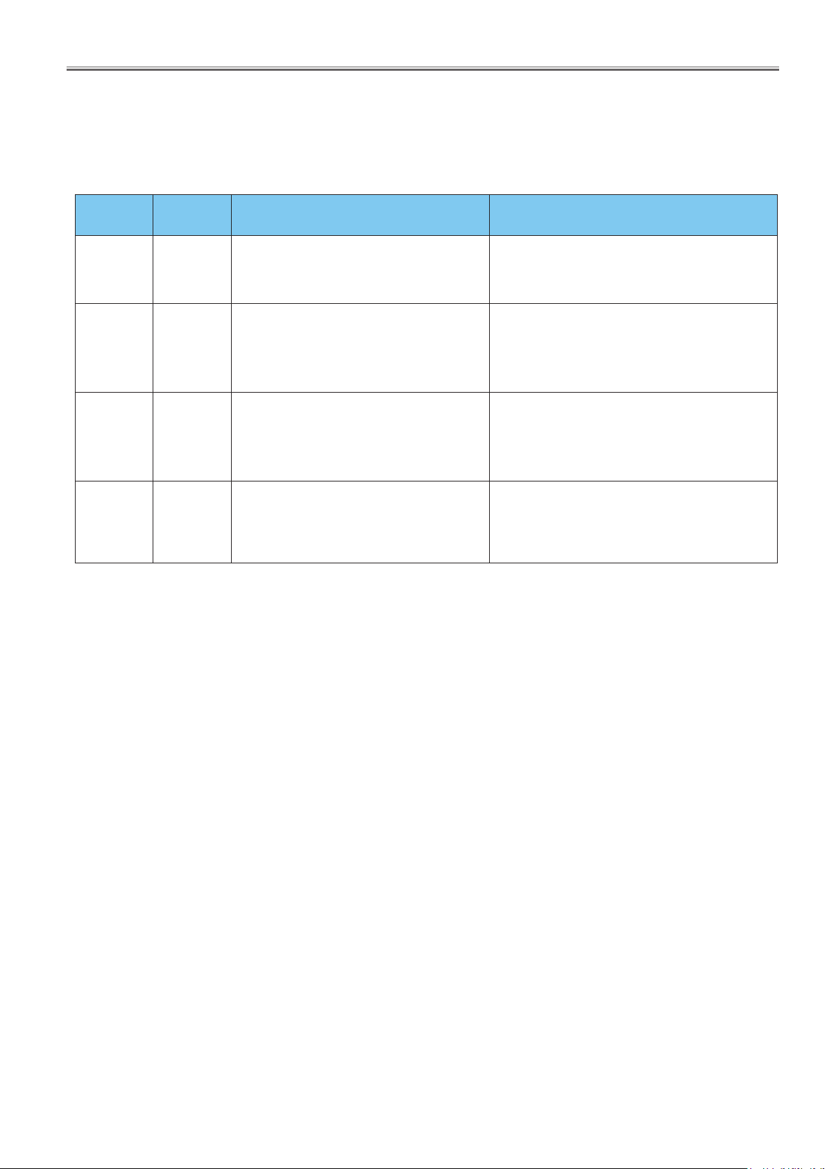
4. 2. Self check of power system
When an abnormality has occurred to the unit, the protection circuit operates and resets to the stand by mode.
At this time, the defective block can be identified by the number of blinks of the Power LED .
<65LFE8>
Blinking
times
4 04
8
9
13 0D
Failure code
(PTCT)
08
09
Contents & Check point Check point (Caused problem)
PANEL 12V SOS
■
Detects +12V voltage fall of power supplied from
A module to Panel module (Timing Controller)
• Abnormality on +12V power line to panel
Boot error for FRC IC.
■
Abnormality on power line to FRC circuit.
• Abnormality on power lines,
+3.3V, +2.5V, +1.8V, +1.0V
(FRC module)
SOUND SOS
■
• Abnormality on power line to audio amplier
circuit
RE GU LATOR SOS
■
Detects abnormal voltage on the regulators on
A module.
• Abnormality on power lines, +1.0V, +1.1V,
+1. 2V, +1. 5V, +1. 8V, +3.3V
Check the 12V lines supplied form P module, and
parts or circuit connected to 12V lines, and connection cable to the T-CON module on the panel.
( P module, A module, LCD panel module)
Check the FRC supply voltage lines on the FR module and parts or circuit connected to supply voltage
lines.
Check the audio supply voltage from P module, and
parts or circuit connected to the audio supply line.
Check the low voltage lines on the A module and
parts or circuit connected to the low voltage line.
* The failure code is the PTCT information displayed on the CD mode in the service mode. Refer to the item [3.3. Software,
EEPROM version and failure display (CD Mode)] for further details.
INF-13
Page 22
SECTION 1 SERVICE INFORMATION
5.2 Abnormal Display
Abnormal Display
Replace LVDS Cable
Replace the main board
Replace the panel
No
No
Yes
No
Enter factory mode
to Reset
Replace the main board
No
Yes
Rese
t
Check the OSD is
normal?
5. Troubleshooting Guide
5.1 No Power
p
p
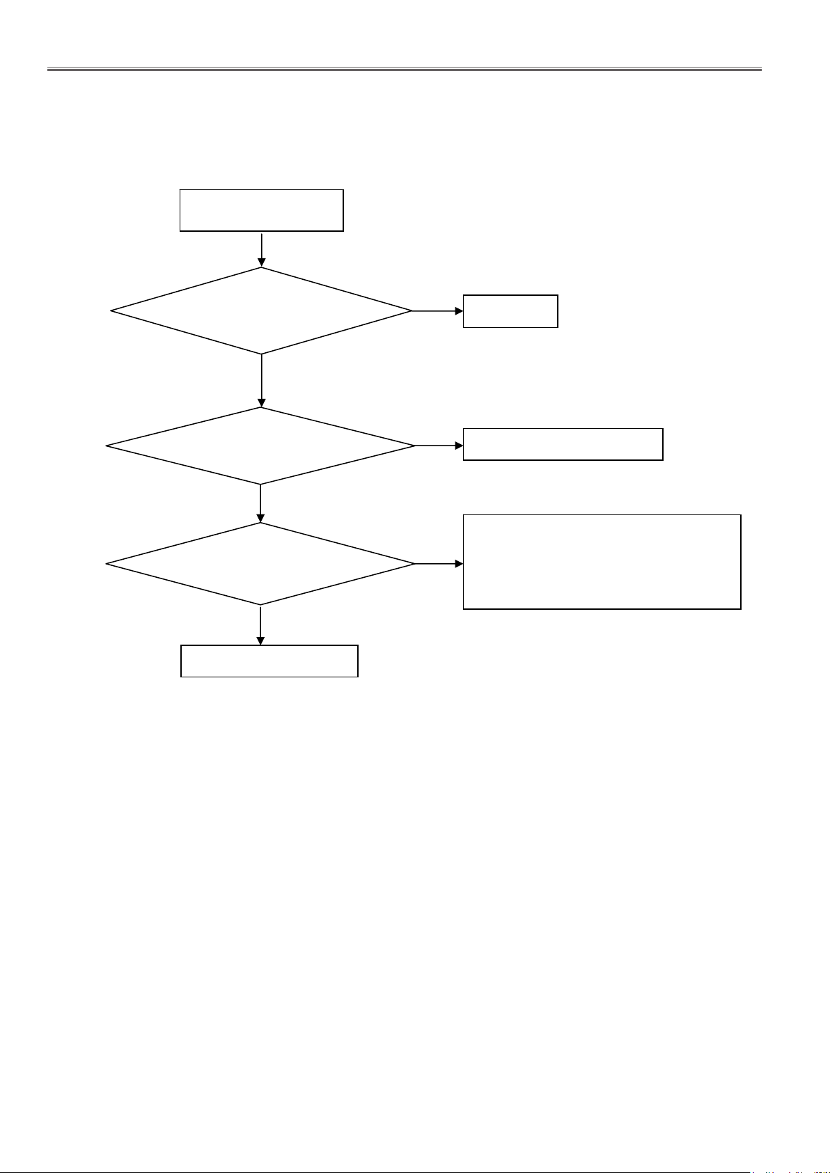
4. 3. Troubleshooting flow
4. 3. 1. No power
<65LFE8>
No power (LED “Off”)
Check the AC input and
the power is “ON”?
Yes
Power board CN903 Pin
2/3/4 out
Yes
Use RC or Key to turn on
the PD
No
ut=5.2V?
No
No
Yes
Power “On”
Replace the Power board
1. RC can turn on the PD and Key can’t,
replace the key board.
2. Key can turn on the PD and RC can’t,
lace the RC.
re
Replace the Main board
INF-14
Page 23
SECTION 1 SERVICE INFORMATION
5.2 Abnormal Display
t
<65LFE8>
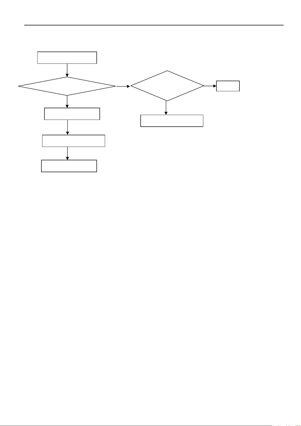
4. 3. 2. Abnormal display
Abnormal Display
Check the OSD is
normal?
No
Replace LVDS Cable
No
Replace the main board
No
Replace the panel
Yes
Enter factory mode
to Reset
No
Replace the main board
Yes
Rese
INF-15
Page 24
SECTION 1 SERVICE INFORMATION
5.3 No Display
g
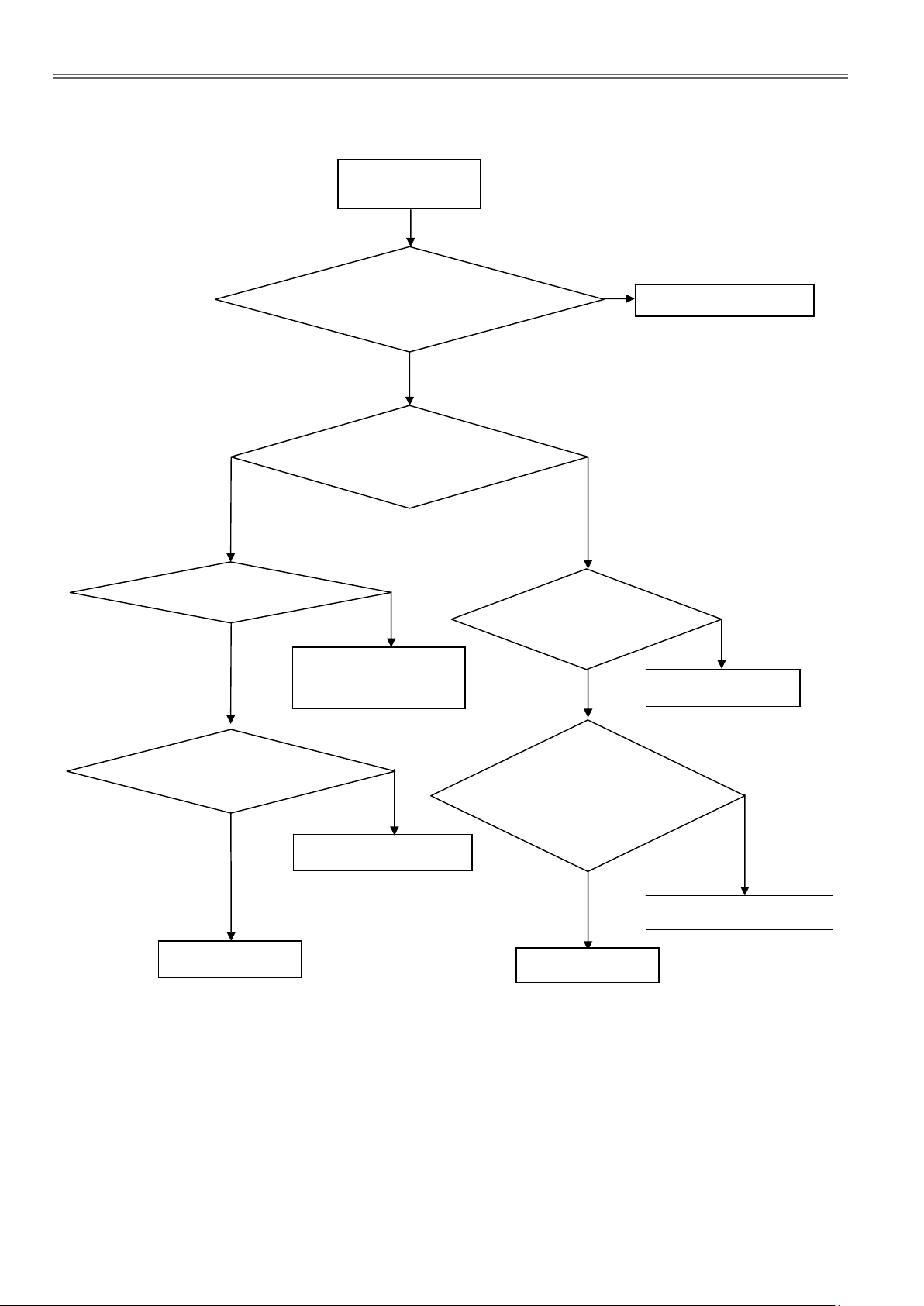
4. 3. 2. No display
<65LFE8>
Check PD is under control and power
Yes
Check the LVDS cable
Yes
No display
(LED No power)
on/off by remote control and
power key?
Yes
Check the backlight is
“On”?
No
Reinsert or replace the
LVDS cable
No
No
Check the P/S and
ON/OFF
nal is available?
si
Yes
Replace the main board
No
Replace main board
Panel Vcc Pin
37/38/39/40= 12V?
Yes
Replace the Panel
No
Replace the main board
Power board
CN904 Pin 11/12/13/14/15=24V
CN905 Pin 6/7/8/9/10=24V
Yes
Replace the Panel
Replace the power board
No
INF-16
Page 25

SECTION 2 DISASSEMBLY PROCEDURES
Disassembly Procedures
Model No. TH-65LFE8U
TH-65LFE8W
TH-65LFE8E
CONTENTS
SECTION 2 DISASSEMBLY PROCEDURES
1. Parts Locations ...........................................DIS-2
1.1. Electrical parts location (P.C. Modules)
2. Parts Disassembly .........................................DIS-3
2.1. Disassembly ow chart
2.2. Preparations
2.3. Rear cover removal
2.4. A module removal
2.5. FR inlet removal
2.6. P module removal
2.7. AC inlet removal
2.8. IR module and the key module removal
2.9. Speakers removal
2.10. Brackets and Screws removal
2.11. LCD panel module
2.12. Wiring connections
3. Replacement of LCD Panel Module ..........................DIS-11
3.1. How to handle LCD panel module
<65LFE8>
DIS-1
(2015-05)
Page 26
SECTION 2 DISASSEMBLY PROCEDURES
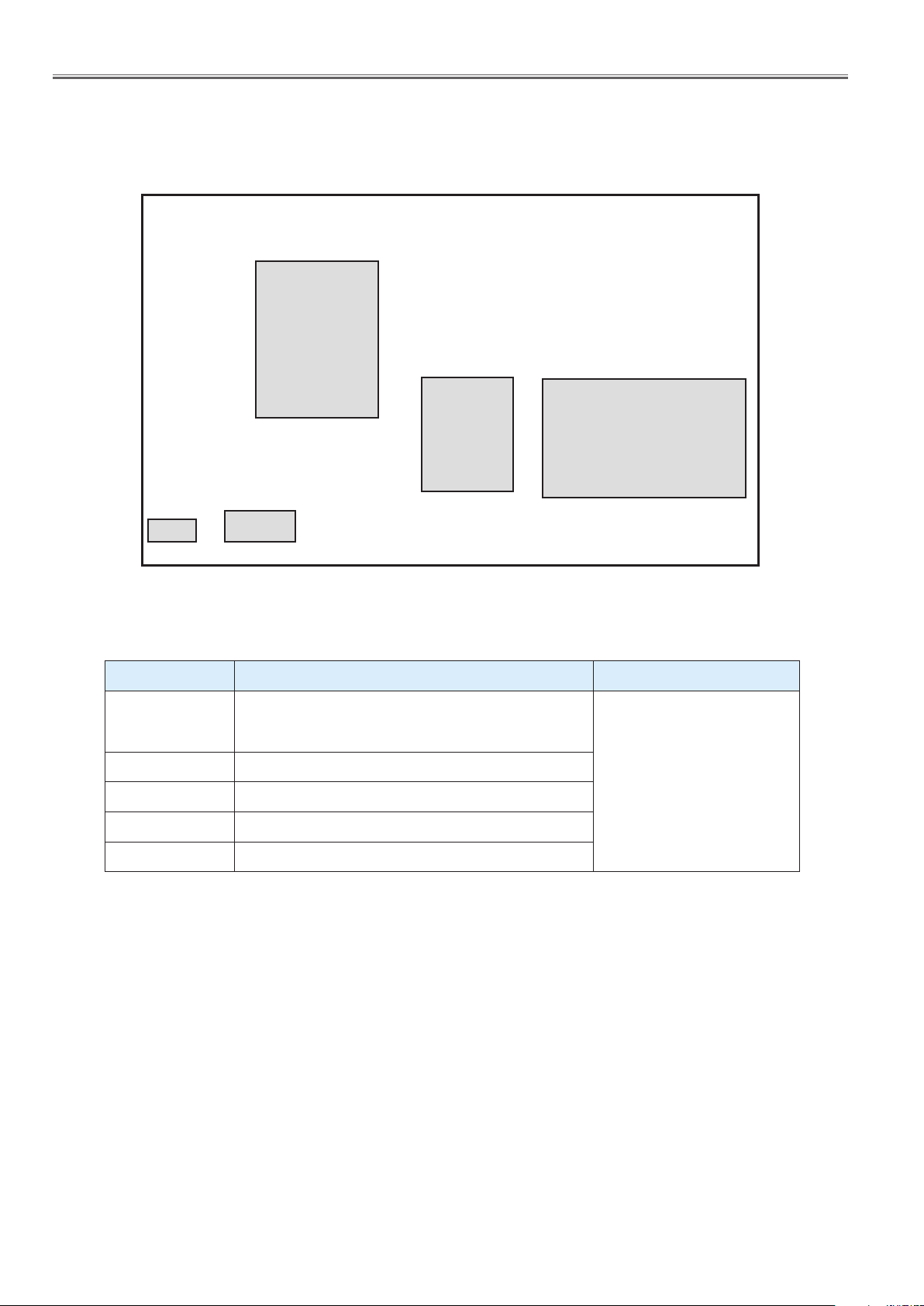
1. Parts Locations
1.1. Electrical parts location (P.C. Modules)
P Module
FR Module
<65LFE8>
A Module
Key ModuleIR Module
Module Function Remark
Speaker out, AV Terminals, HDMI in, DVI in, VGA in, USB
A Module
IR Module Remote receiver, LED
P Module Power (AC/DC). DC-DC
Key Module Control button, Power switch
FR Module Double speed processor
in, PC in, DP in, LAN in, HD Base-in/out, RS232C-in/out,
IR-trough
All modules are non serviceable
and should be exchanged for
repair.
DIS-2
Page 27
SECTION 2 DISASSEMBLY PROCEDURES
2. Parts Disassembly
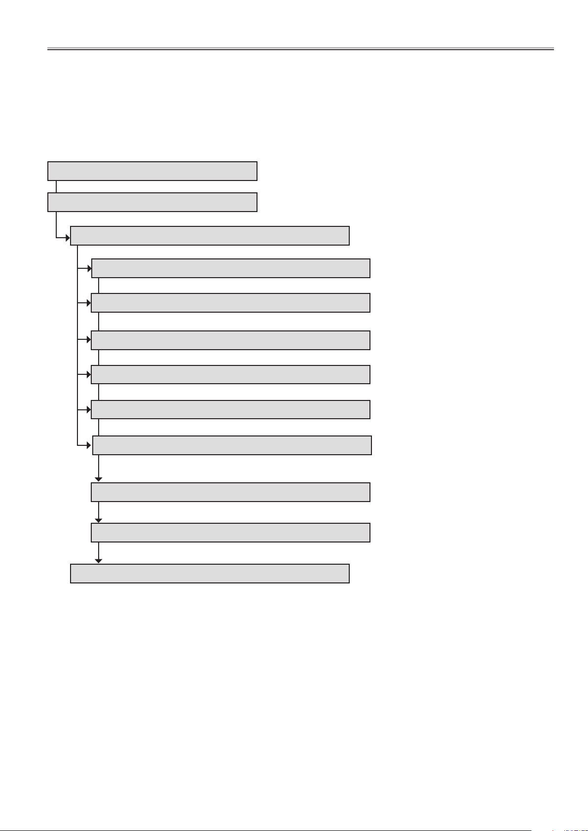
2.1. Disassembly flow chart
* Before Disassembling, turn the display off and disconnect the power plug from the wall outlet.
* To assemble, reverse the disassembly procedures.
* When tore off sticky tapes, please use a new thing without reusing it on the occasion of assembling.
Completed Product
2.2. Preparations
2.3. Rear cover removal
2.4. A module removal
2.5. FR module removal
<65LFE8>
2.6. P module removal
2.7. AC inlet removal
2.8. IR Module and Key Module removal
2.9. Speakrs removal
2.10. Brackets and screws removal
2.11. LCD panel module removal
2.12. Wire connections
DIS-3
Page 28
SECTION 2 DISASSEMBLY PROCEDURES
TH-50LFC70U/TH-50LFC70W
discharge from an electrolytic condenser, please wait for 1
minute after the power supply end.
towel, and turn the front of the unit down, and lay down so
that the entire monitor rides on a table completely.
7.3. Replacement of WI-FI Module
(Dongle)
1. Remove the screw and then remove the WI-FI Module
(Dongle).
3. Remove the screws and BKT.
D
C
L
3
<65LFE8>
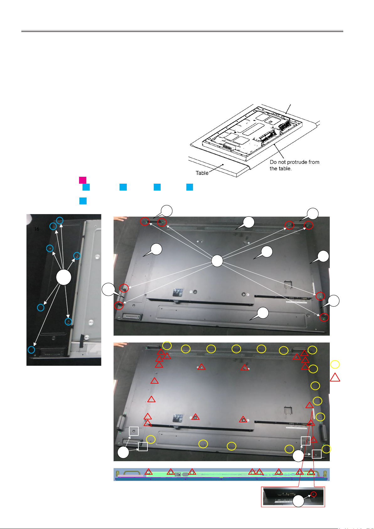
2.2. Preparations
• When you exchange modules or board, in order to make it discharge from an electrolytic condenser, please wait for 1 minute
after the power supply end.
• To avoid damaging the LCD panel, lay out a soft cloth or towel, and turn the front of the unit down, and lay down so that the
entire monitor rides on a table completely.
Note:When local pressure is suppressed, Mura of the picture image may be seen. In this case ,please carry out aging by
burn in mode. (Refer to INF.7 in the SECTION 1)
Soft cloth or Towel
Precautions when replacing each component
• When you replace each component, please be sure to
carry out following procedure as below.
• Be careful not to overtighten the screws when replacing
each module.
• Please remove a clamper and a wire processing tape
if needed in the repair.
2.3. Rear cover removal
1. Remove 8 screws H , and remove the handles.
2. Remove 27 screws C ,16 screws D , 1 screws E ,4 screws F .
3. Remove rear coverL,BTM,TOP,MID.(Ref. No.7,8,9,10).
4. Remove 7 screws D and remove rear cover R.(Ref. No.6).
12
9
12
D
12
6
H
10
8
7
12
D
C
F
F
E
DIS-4
Page 29
SECTION 2 DISASSEMBLY PROCEDURES
I
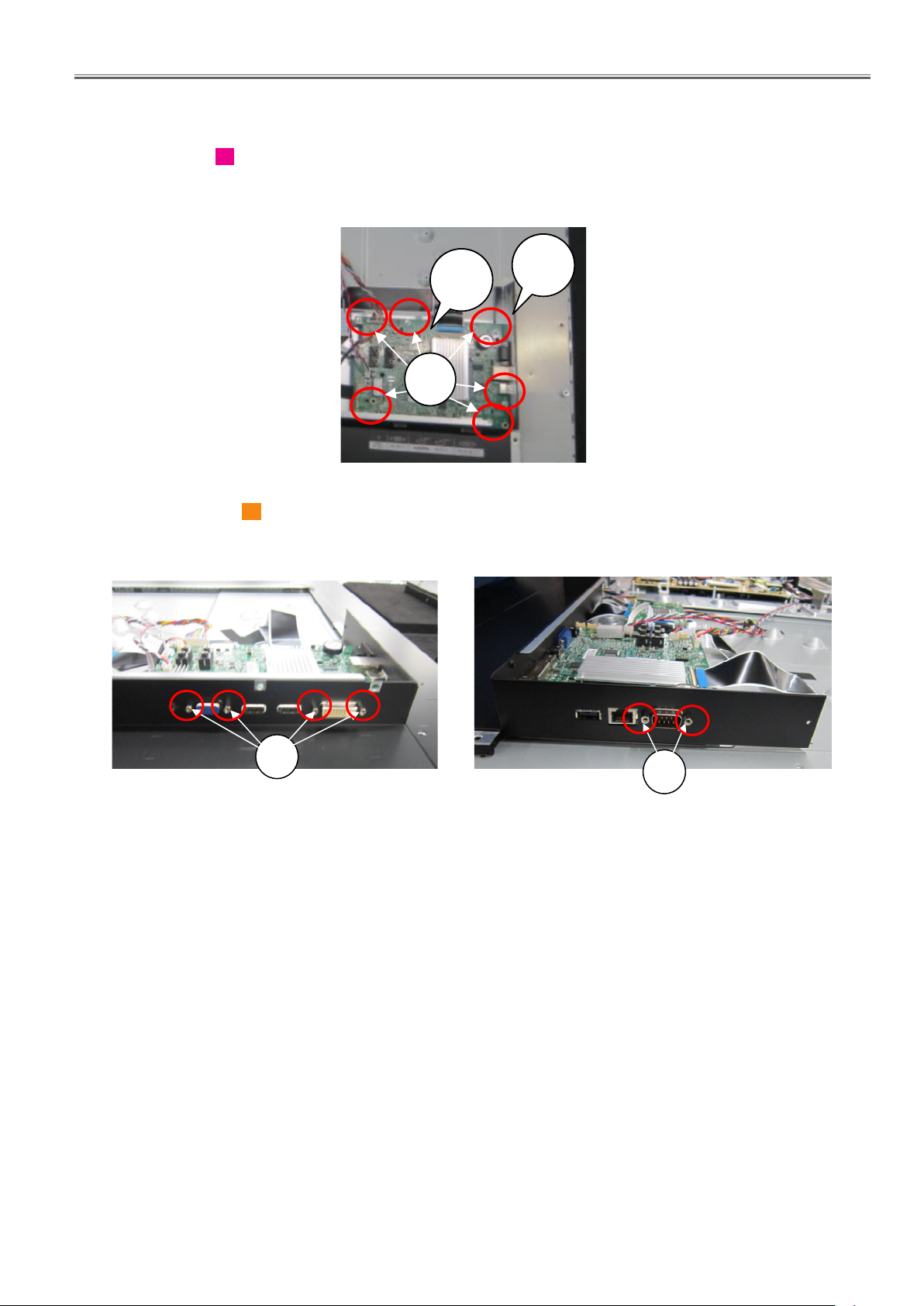
2.4. A module removal
1. Remove the rear cover MID.
2.Remove 6 screws G on A module(Ref.No.14).
3. Disconnect the connectors on A modules.
<65LFE8>
4
IO bracket
14
G
4. Remove 6 hex screws I (on VGA and DVI terminals and SERIAL terminals), and then take
A module off from the IO bracket(Ref.No.4) and rear cover BTM.
I
Hex screws on VGA and DVI terminals
Hex screws on serial terminal
I
DIS-5
Page 30
SECTION 2 DISASSEMBLY PROCEDURES
I
G
20
21
4
14
I
I
G
G
G
20
21
19
4
14
I
G
21
4
14
D
D
C
L
3
D
2
1
5
B
2.5. FR module removal
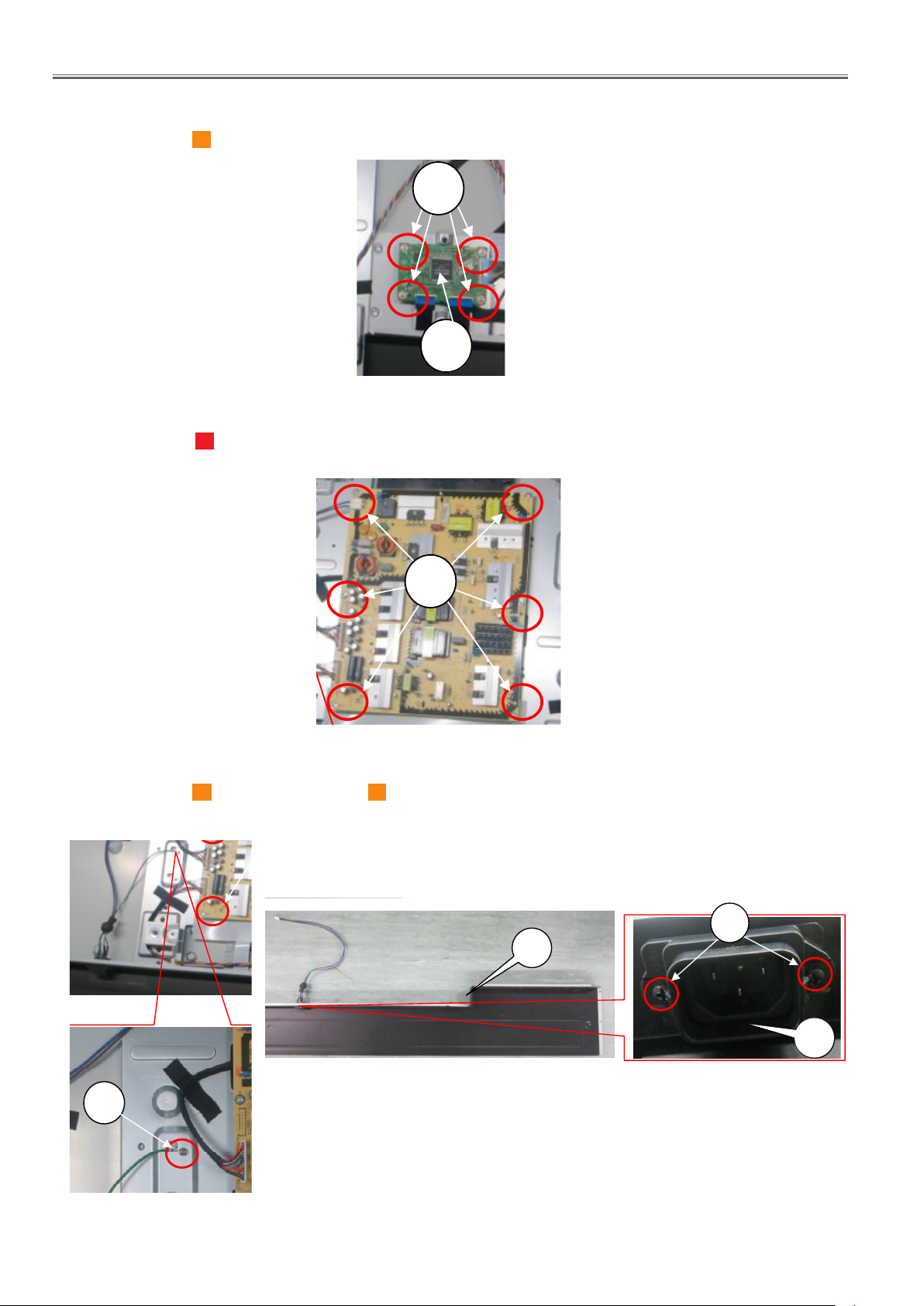
1. Remove 4 screw G on the FR module and remove the FR module from the bracket.(Ref.No.19)
G
19
2.6. P module removal
1. Remove 6 screws G and disconnect connectors on P module.
2. Remove P module.
<65LFE8>
2.7. AC inlet removal
1. Remove 1 screw I and remove 2 screws of K ,then remove the cover cable (Ref.No.35).
2. Remove the AC Inlet from the rear cover BTM(Ref.No.8).
G
AC inlet
8
K
I
35
35
DIS-6
Page 31
SECTION 2 DISASSEMBLY PROCEDURES
4. Remove the IR board and KEY board.
A
I
I
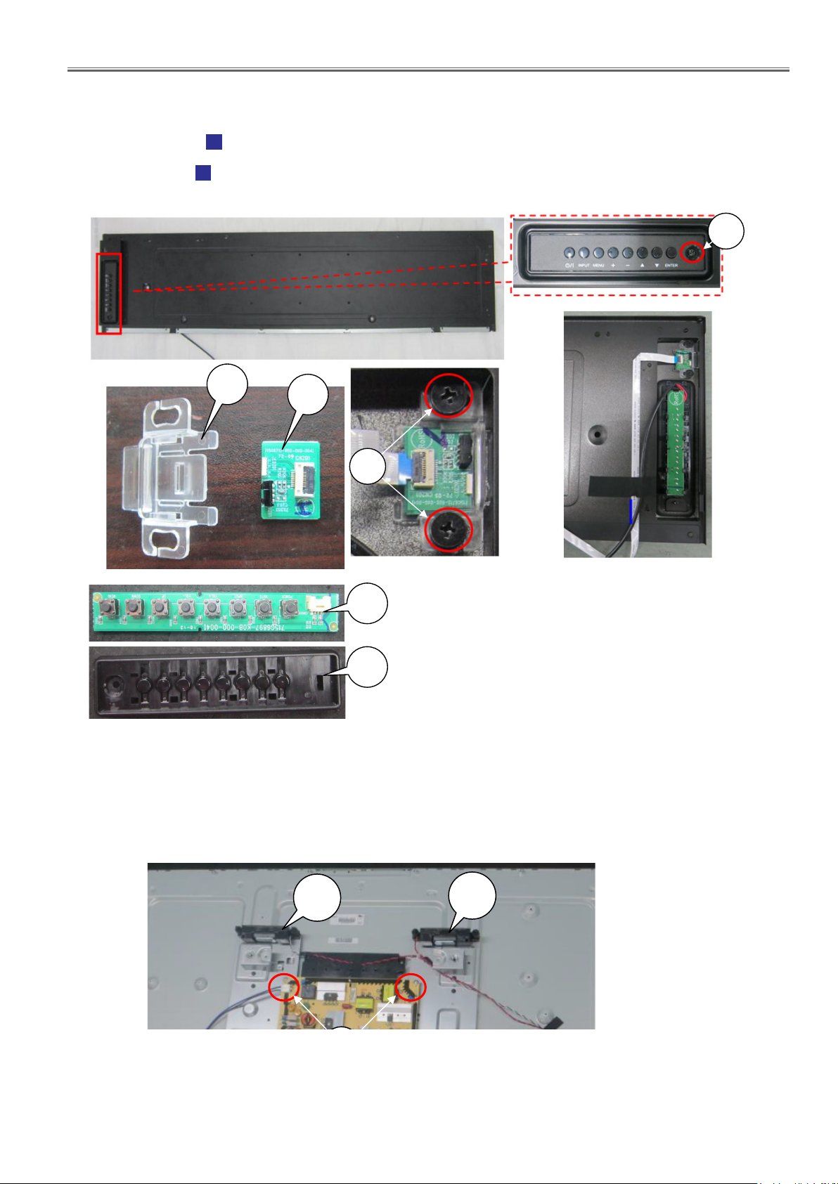
2.8. IR module and the key module removal
1. Remove the rear cover R.
2. Remove 2 screws D to take IR board (Ref.No.18) off from the rear cover R.
Note: Pay attention not to tear off the FPC cable from the connector.
3. Remove 1 screw E to remove the Key Module bracket.
4. Unhook the hooks on the bracket to remove the Key module.
<65LFE8>
E
13
2.9. Speakers removal
18
D
17
[17] Key module
11
[11] Key SW module
1. Remove the rear cover MID.
2. Remove the Speakers (Ref.No.20,21) from the LCD panel.
20
21
DIS-7
Page 32
SECTION 2 DISASSEMBLY PROCEDURES
3. Remove the screws and BKT.
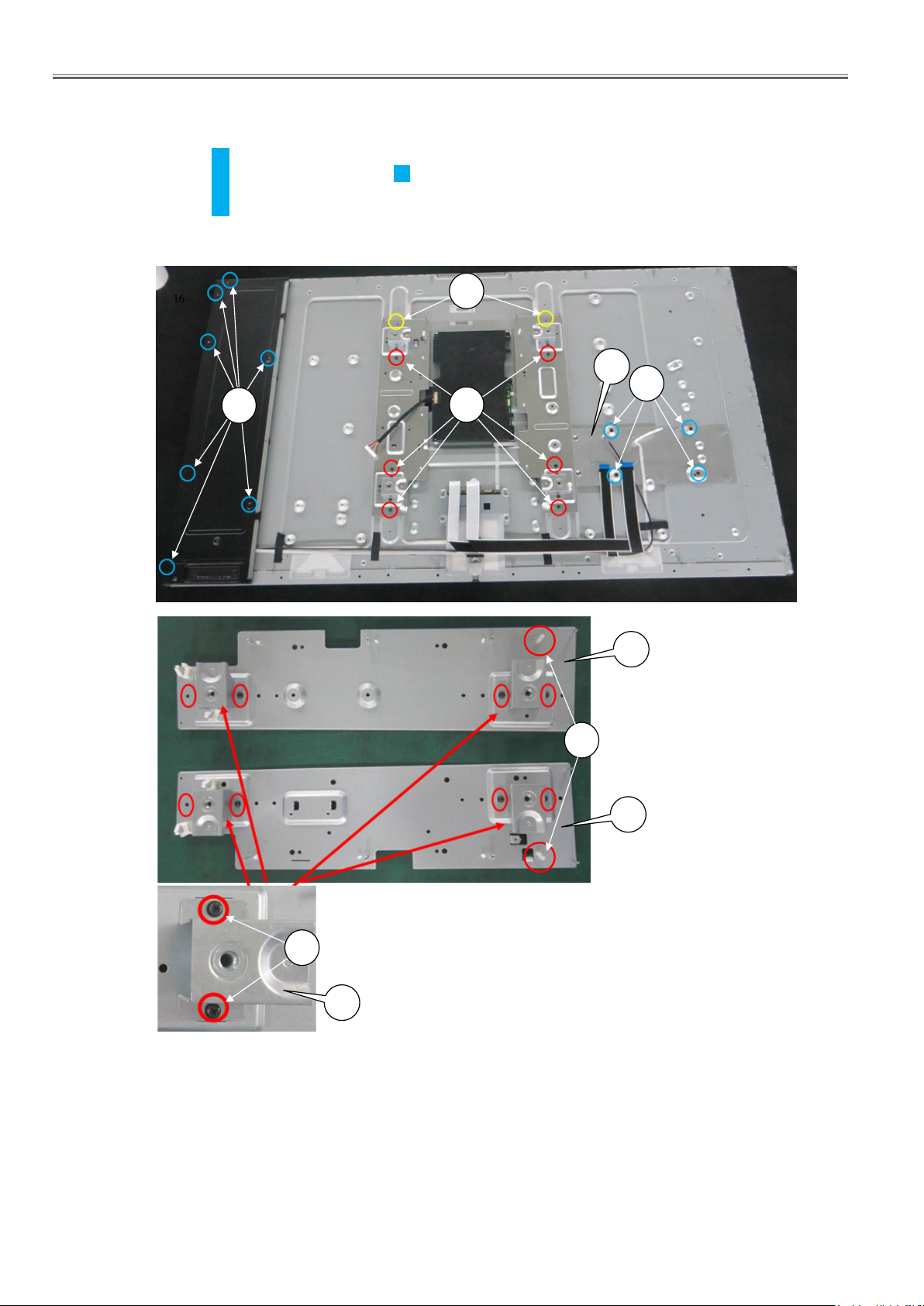
2.10. Brackets and Screws removal
1. Remove rear cover L,R,TOP,MID,BTM.
2. Remove 4 screws of D and remove the PCB main board BTM Brachet. (Ref.No.3).
3. Remove 6 screws of C and remove 2 screws of L and remove the Bracket. (Ref.No.1,2).
4. Remove 8 screws of D and remove the Vesa brackets (Ref.No.5) on the Power R brachet and MID brachet.
5. Remove 2 screws of B .
<65LFE8>
D
[1] Power R Bracket
L
C
[2] MID Bracket
3
D
[2] MID Bracket
2
B
D
1
[1] Power R Bracket
5
DIS-8
Page 33
SECTION 2 DISASSEMBLY PROCEDURES
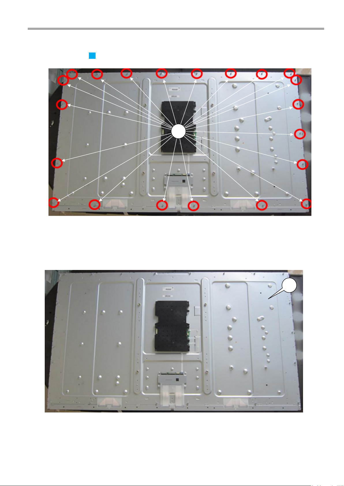
5. The panel.
6. Remove 21 screws of A on the LCD Panel.
<65LFE8>
A
2.11. LCD panel module
1. Disconnect cables from the boards on the LCD panel module.
16
[16] LCD Panel Module
DIS-9
Page 34
SECTION 2 DISASSEMBLY PROCEDURES
9 Wiring Connection Diagram
9.1. Caution statement.
Caution:
Please confirm that all flexible cables are assembled correctly.
Also make sure that they are locked in the connectors.
Verify by giving the flexible cables a very slight pull.
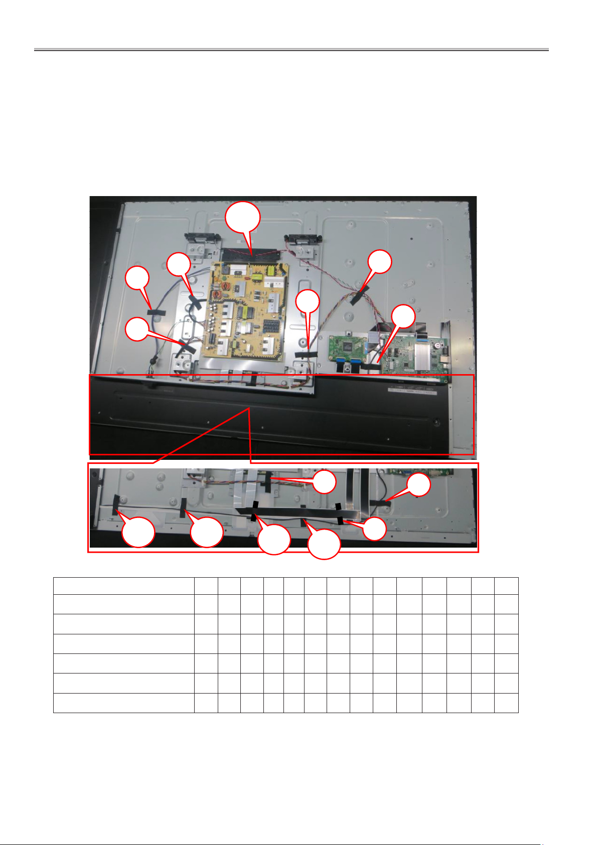
9.2. Wiring
2.12. Wiring connections
2.12.1 Caution statement
Caution:
Please confirm that all flexible cables are assembled correctly.
Also make sure that they are locked in the connectors.
Verify by giving the flexible cables a very slight pull.
2.12.2. Wiring
14
<65LFE8>
2
1
3
12 13
11
5
4
7
6
9
10
8
A Module - P Module
P Module-AC SOCKET
P Module-Panel
A Module - Spearker
A Module - IR Board
A Module - Key Board
1
2 3 4 5 6 7 8 9 10
● ● ● ● ●
●
●
● ●
● ● ● ● ● ● ●
● ● ● ● ● ● ●
DIS-10
11 12 13 14
Page 35
SECTION 2 DISASSEMBLY PROCEDURES
TH-50LFC70U/TH-50LFC70W
7.15. Replacement of LCD Panel Assy and Front Glass
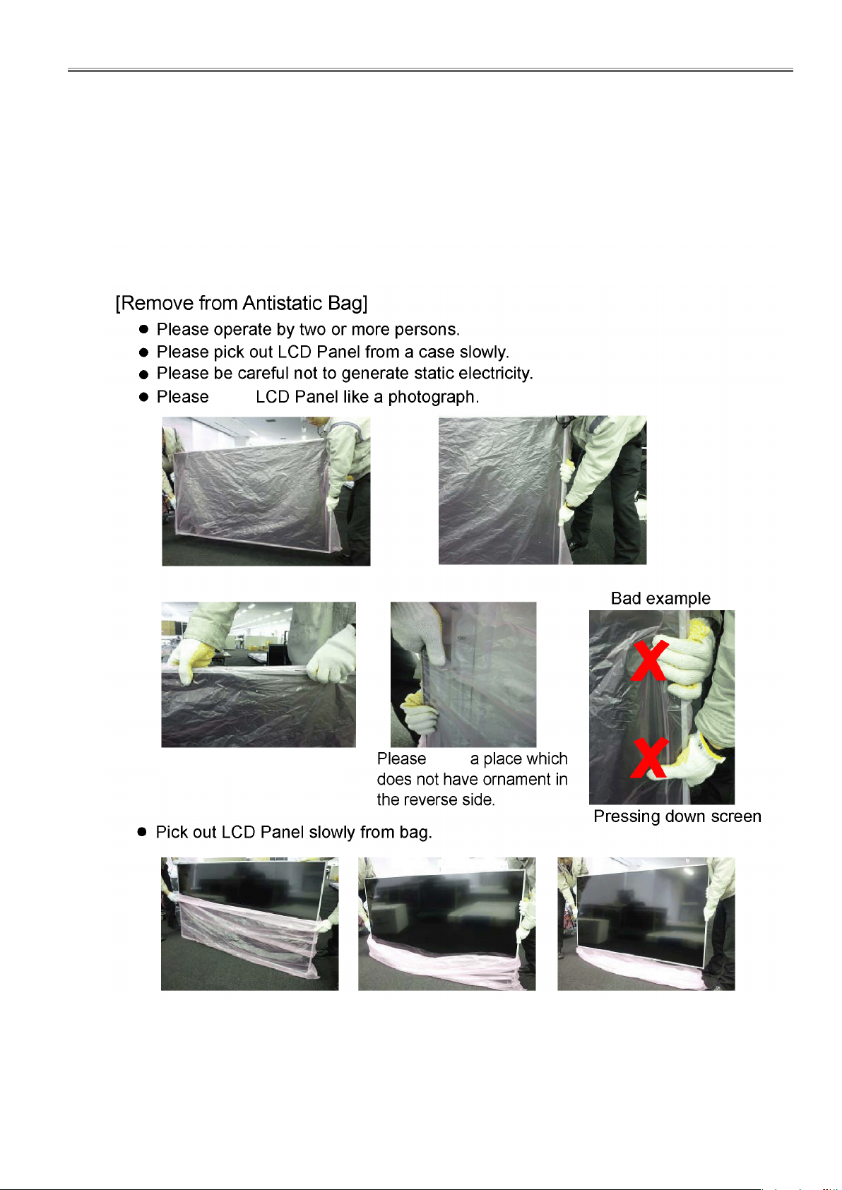
Attention when removing LCD Panel
• Please work by two or more persons.
• Please work putting a glove.
Caution about LCD Panel Assy
• When replacing the LCD module, please work to be aware of the following.
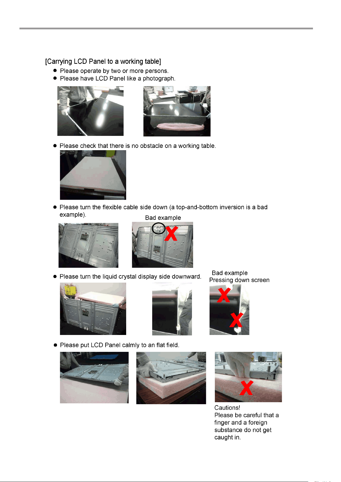
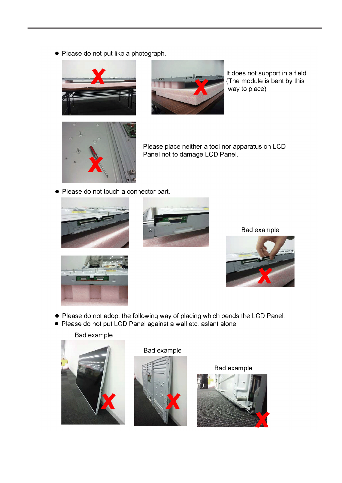
3. Replacement of LCD Panel Module
Attention when removing LCD panel module
• Please work by two or more persons.
• Please work putting a glove.
<65LFE8>
Caution about LCD panel module
• When replacing the LCD panel module, please work to be aware of the following.
3.1. How to handle LCD panel module
hold
Hold a bezel.
hold
DIS-11
Page 36
SECTION 2 DISASSEMBLY PROCEDURES
TH-50LFC70U/TH-50LFC70W
<65LFE8>
DIS-12
Page 37
SECTION 2 DISASSEMBLY PROCEDURES
TH-50LFC70U/TH-50LFC70W
<65LFE8>
DIS-13
Page 38

SECTION 2 DISASSEMBLY PROCEDURES
<65LFE8>
DIS-14
Page 39

SECTION 3 ADJUSTMENTS
Adjustments
Model No. TH-65LFE8U
TH-65LFE8W
TH-65LFE8E
CONTENTS
SECTION 3 ADJUSTMENTS
1. Software Update Procedures ...............................ADJ-2
1.1. MAIN MCU software updating
1.2. SUB MCU software updating
2. USB Cloning .............................................ADJ-6
2.1. Copy Data
2.2. Cloning procedure (General Mode)
2.3. Cloning procedure (Service Mode)
3. Serial no. writing .........................................ADJ-8
3.1. Tools and preparation
3.2. Writing procedure
3.3. Conrmation of version
<65LFE8>
ADJ-1
Page 40
SECTION 3 ADJUSTMENTS
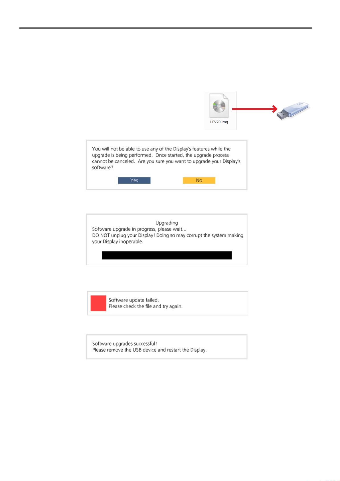
1. Software Update Procedures
* The software can be updated as the procedure below.
1.1. MAIN MCU software updating
1.1.1. Tools and preparation
1. USB memory : It stores a file for updating. (FAT16 format)
2. Updating file (LFE8_Vxxx.img) : Download from the service web site and
store it into the top directory of USB memory.
1.1.2. Updating procedure
1. Turn on the Display and insert the USB memory into the slot of USB.
2. The message below will appear on the screen.
<65LFE8>
3, Select [Yes] with [tu] buttons and press the [ENTER] button to start updating.
If the updating fails, the message below will appears.
Confirm that updating file is stored into the USB memory correctly and try it again.
4. The message below will appear when the updating has been finished correctly.
After finishing the updating, as the Display turn on automatically, remove the USB memory from the slot immediately otherwise the message to update will appear again.
Note: If the setting of [Network Control] is "On", the Display will not turn on automatically. First remove the USB memory and
the turn it on manually.
ADJ-2
Page 41
SECTION 3 ADJUSTMENTS
<65LFE8>
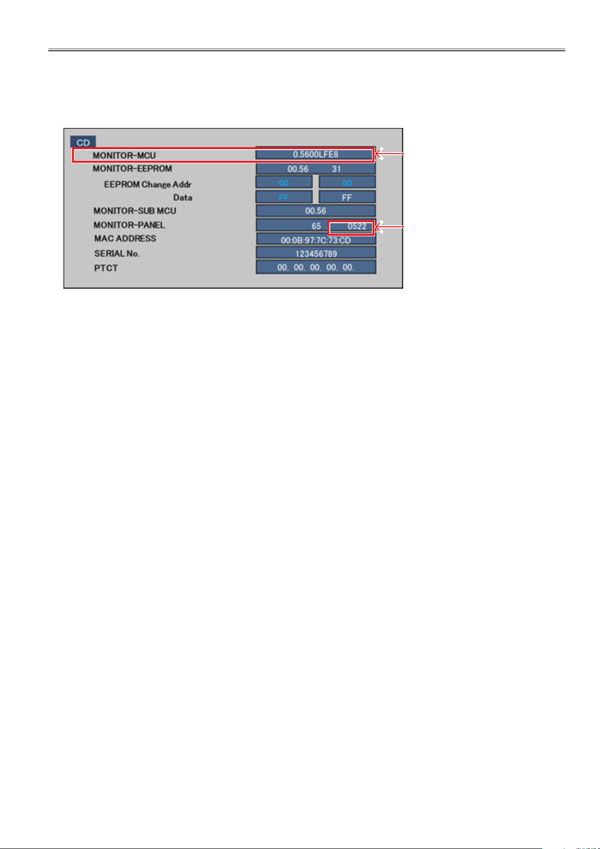
1.1.3. Confirmation of version
1. Display the CAT mode (Refer to Section 1 - 3.1.)
2. The CAT mode menu appears on the screen. Select the [CD Mode] menu with [pq] buttons and press the [MUTE] button
for more than 3 seconds to enter the CD mode.
Main CPU rmware version
FRC rmware version
ADJ-3
Page 42
SECTION 3 ADJUSTMENTS
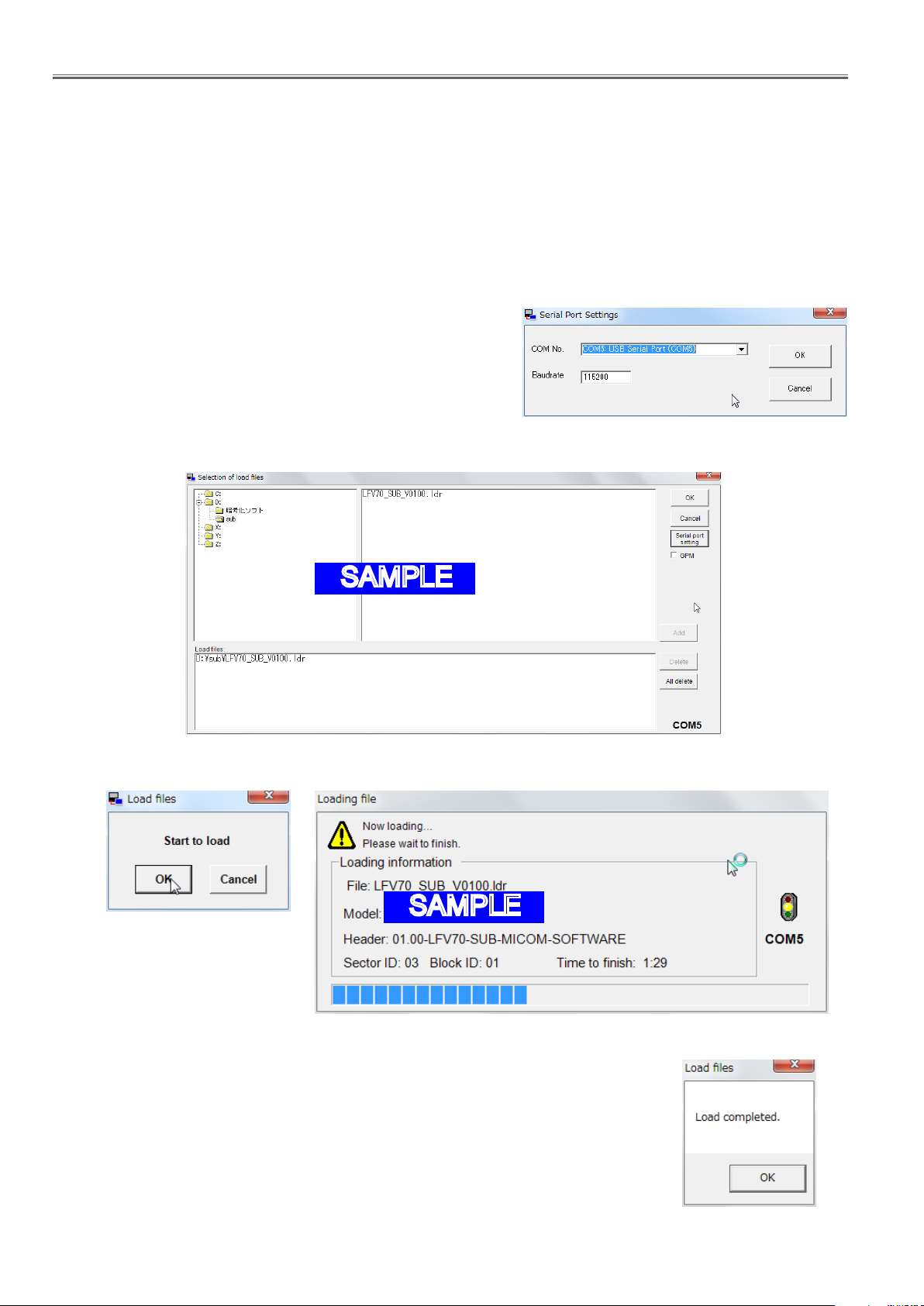
1.2. SUB MCU software updating
1.2.1. Tools and preparation
1. Computer : Used for firmware transforming
2. Communication cable : D-sub 9pin (female/female RS-232C straight)
3. Software & updating file : SerialLoader v1.00& firmware (LFE8_SUB_Vxxxx.ldr), download from ser vice web site.
4. Extract the software and file package to your favorite directory on your computer.
5. Connect the serial terminal (SERIAL-IN) and PC with an RS-232C cable.
1.2.2. Updating procedure
1. Start up the updating software [SerialLoader.exe].
2. Choose available COM port with pull down menu and click [OK]. The
baudrate should be used with "115200".
3. On the left window, browse and select a folder where the updating file
is stored. The firmware file is listed on the right window and select it
then click [Add]. The selected firmware will listed on the bottom window.
<65LFE8>
SAMPLE
4. Click [OK]. The another confirmation window will appear and then click [OK] to start updating.
SAMPLE
* During updating, Do not disconnect
the AC cord or serial cable other-
wise the Display may not turn on.
5. After finishing the updating, the window below appear and click [OK] to close the software.
6. Turn of the Main switch and then on again. Confirm the version number in the CD mode of
CAT mo de .
ADJ-4
Page 43
SECTION 3 ADJUSTMENTS
<65LFE8>
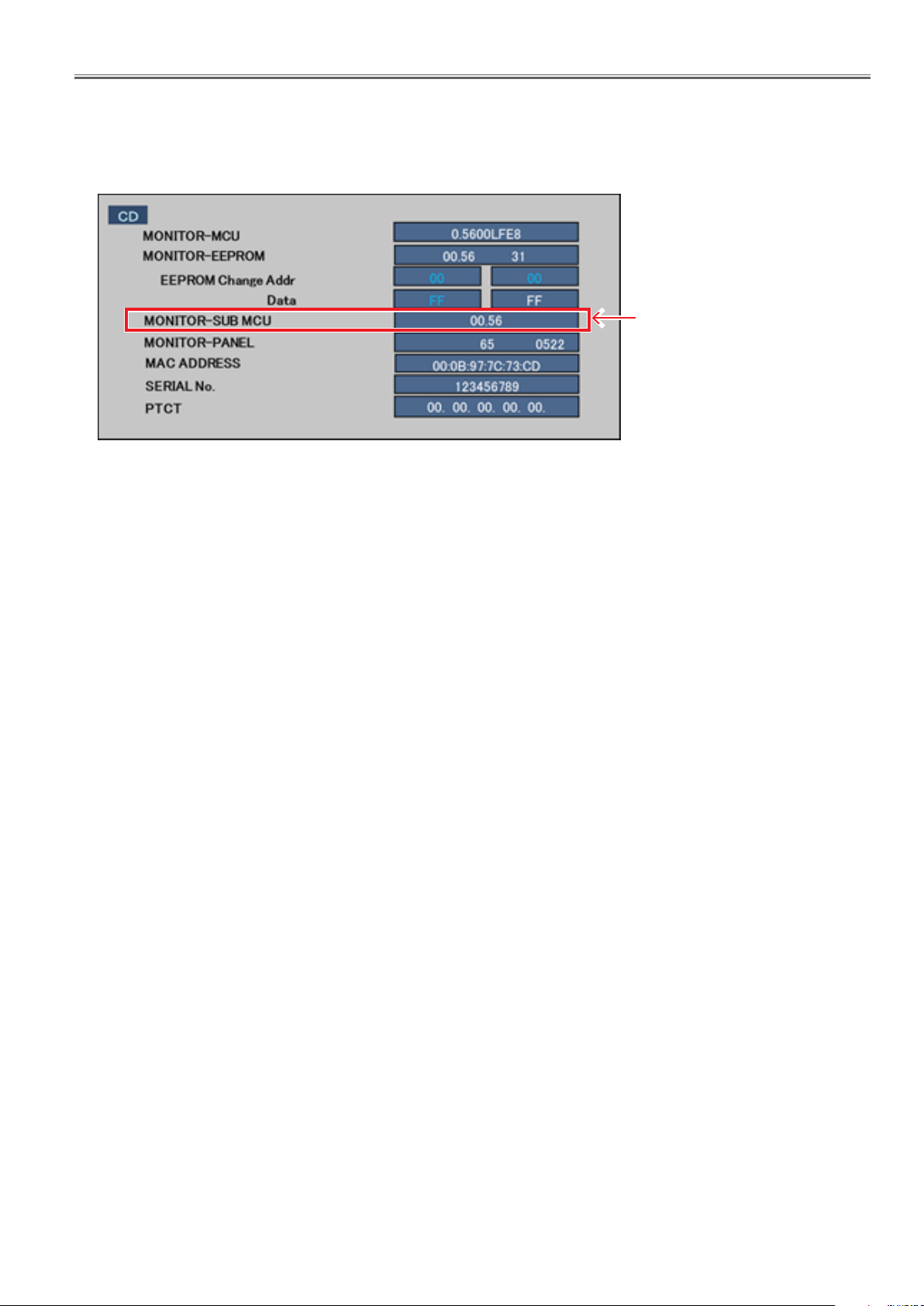
1.2.3. Confirmation of version
1. Display the CAT mode (Refer to Section 1 - 3.1.)
2. The CAT mode menu appears on the screen. Select the [CD Mode] menu with [pq] buttons and press the [MUTE] button
for more than 3 seconds to enter the CD mode.
Sub CPU rmware version
ADJ-5
Page 44
SECTION 3 ADJUSTMENTS
<65LFE8>
2. USB Cloning
2.1. Copy Data
1) General Mode/Service Mode(Selected User Menu Data)
"Picture Adjustment Data", "Sound Adjustment Data", "Initial Setting", "Position Data", "Options Menu setting",
"Adjustment Data"
*Following Data is not copied.
Date and Time
Network setting: LAN Setting
Options : Display ID
2) Service Mode (Selected Board Replace)
All data except Date and Time
Note: The Copy of Data (USB Memory → Display) is not available when Data of Model and Size and
Destination do not match.
2.2. Cloning procedure (General Mode)
1. Insert USB Memory to the USB interface.
2. Press the [SETUP] button to display the setup menu on the screen. Select [OSD language] menu with [pq] buttons and
press and hold the [ENTER] button for more than 3 seconds.
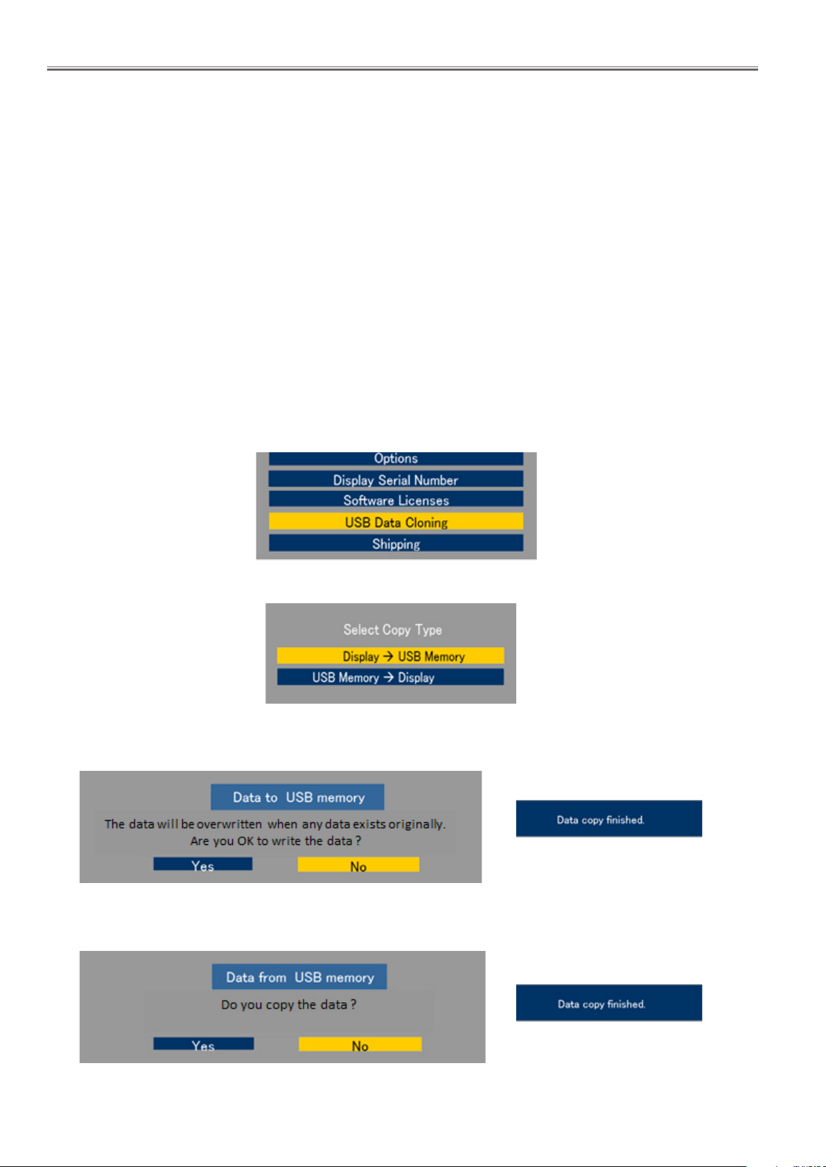
The below window will appear. (USB Data cloning is gray out when USB Memory is not inserted.)
3. Select [USB Data Cloning] menu with [pq ] buttons and press enter button. The below window will appear.
3.1. Display→USB Memory
Select [Display→USB Memory] and then click [ Yes] to start cloning.
After finishing the copying, the window below appear.
3.2. USB Memory→Display
Select [USB Memory→Display] and then click [Yes] to start cloning.
After finishing the copying, the window below appear.
4. Turn off the Main switch and then on again. Confirm the version number in the CD mode of CAT mode.
ADJ-6
Page 45
SECTION 3 ADJUSTMENTS
<65LFE8>
2.3. Cloning procedure (Service Mode)
1. Insert USB Memory to the USB interface.
2. Display the CAT mode (Refer to Section 1 - 3.1.)
3. Press the [SETUP] button to display the setup menu on the screen. Select [OSD language] menu with [pq ] buttons and
press and hold the [ENTER] button for more than 3 seconds.
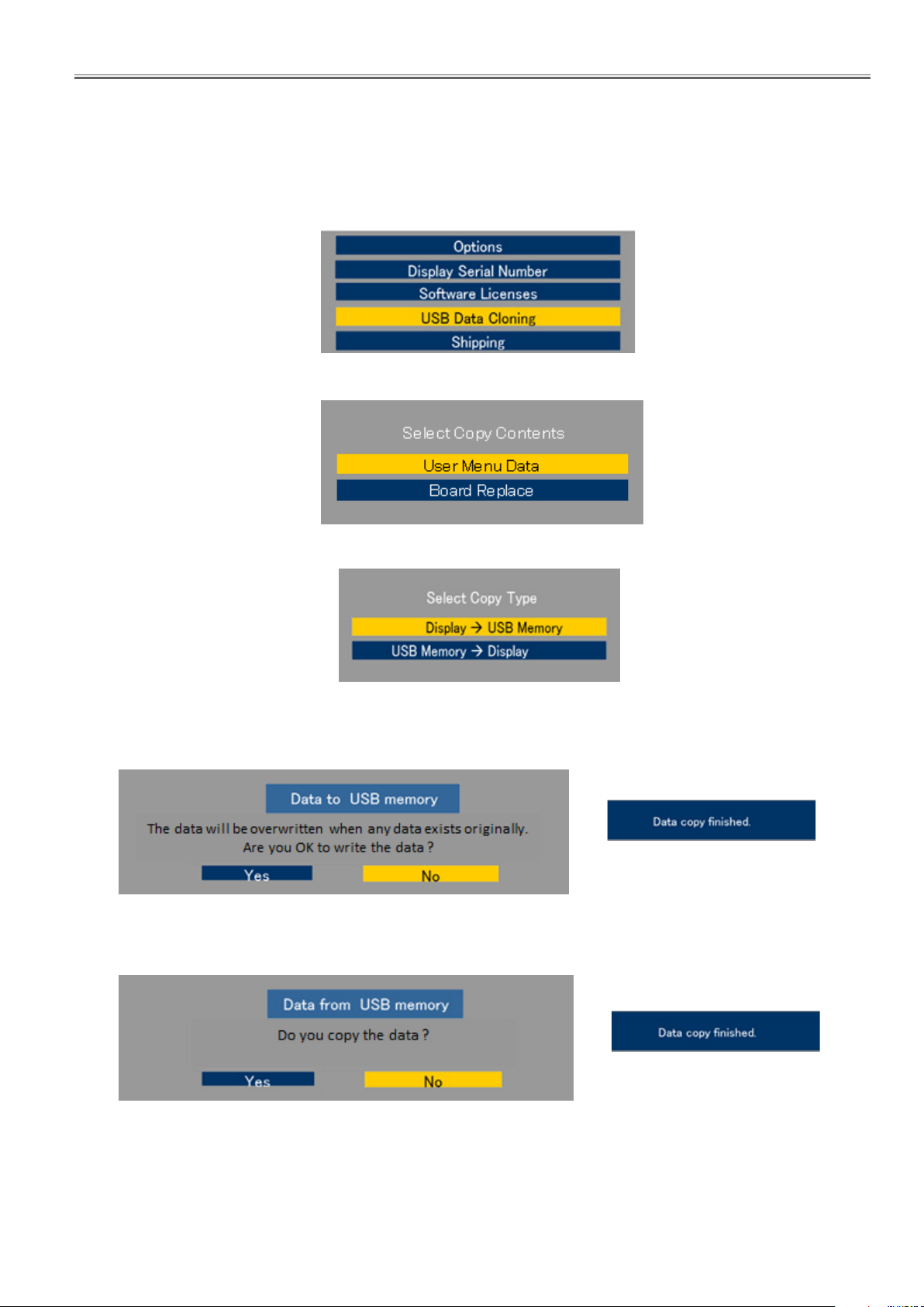
The below window will appear. (USB Data cloning is gray out when USB Memory is not inserted.)
4. Select [USB Data Cloning] menu with [pq ] buttons and press enter button. The below window will appear.
5. Select [Board Replace] menu with [pq] buttons and press enter button. The below window will appear.
5.1. Display→USB Memory
Select [Display→USB Memory] and then click [ Yes] to start cloning.
After finishing the copying, the window below appear.
5.2. USB Memory→Display
Select [USB Memory→Display] and then click [Yes] to start cloning.
After finishing the copying, the window below appear.
6. Turn off the Main switch and then on again. Confirm the version number in the CD mode of CAT mode.
ADJ-7
Page 46
SECTION 3 ADJUSTMENTS
3. Serial no. writing
3.1. Tools and preparation
1. Computer : Used for serial no. writing
2. Communication cable : D-sub 9pin (female/female RS-232C straight)
3. Software : SerialNoMoveTool_v102.exe, download from service web site.
4. Extract the software to your favorite directory on your computer.
5. Connect the serial terminal (SERIAL-IN) and PC with an RS-232C cable.
3.2. Writing procedure
1. Take a note of serial no. printed on the rating label of the back
cover.
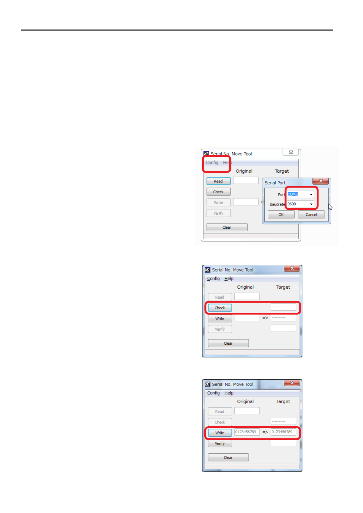
2. Turn the Display on and start the writing tool [SerialNoMoveTool_
v102.exe] with administrator rights.
3. Choose available COM port and baudrate: 9600 with pull down
menu and click [OK].
<65LFE8>
4. Click [Check].
The serial no. set on the board will appear on the text box.
The "---------" will appear in case of a new board supplied as ser-
vice parts.
Note: If some sort of serial no. appears, the serial no. has been set
on the board once. In this case, it cannot overwrite existing
serial no.
5. Enter the serial no. taken in step1 and click [Write].
The another confirmation window will appear and then click [Yes] to
execute the writing.
ADJ-8
Page 47
SECTION 3 ADJUSTMENTS
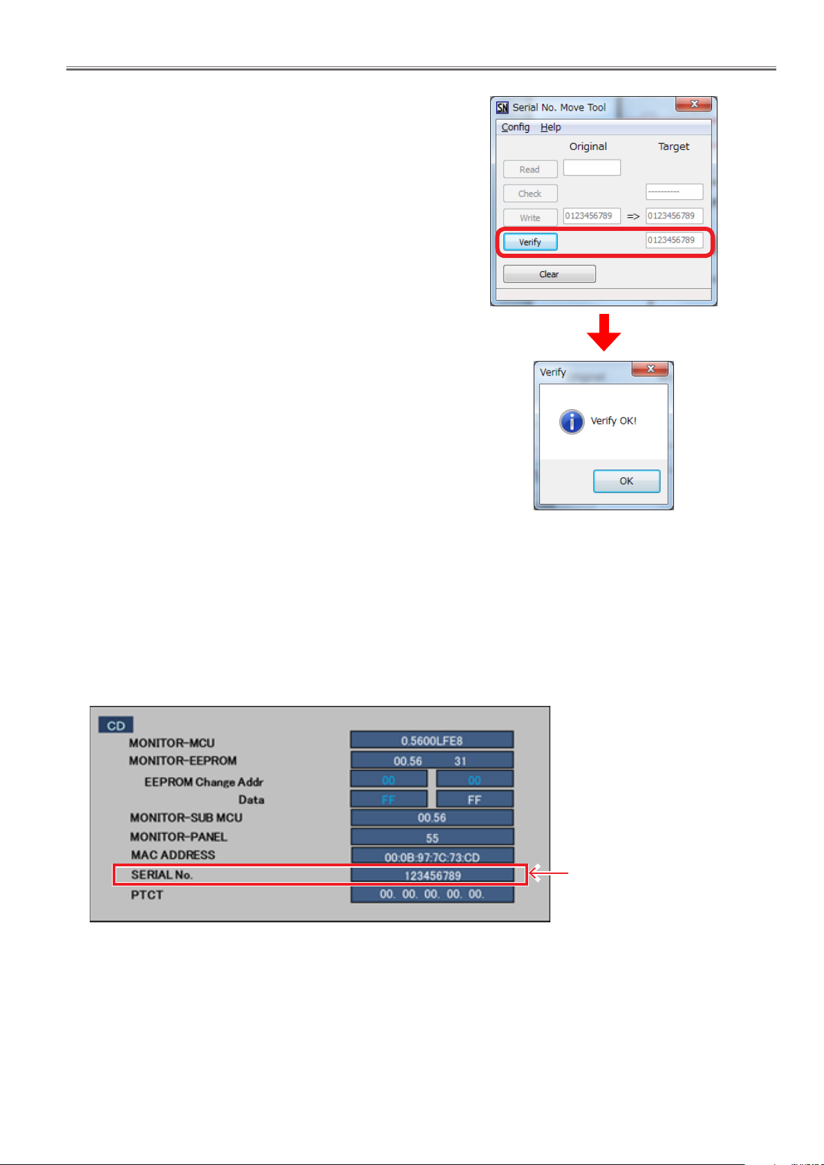
6. After finishing the writing, click [Verify] to verify whether the serial
no. has been written on the board correctly.
<65LFE8>
3.3. Confirmation of version
1. Display the CAT mode (Refer to Section 1 - 3.1.)
2. The CAT mode menu appears on the screen. Select the [CD Mode] menu with [pq] buttons and press the [MUTE] button
for more than 3 seconds to enter the CD mode.
Serial no. display
ADJ-9
Page 48

SECTION 3 ADJUSTMENTS
<65LFE8>
ADJ-10
Page 49

SECTION 4 DIAGRAMS
Diagrams
Model No. TH-65LFE8U
TH-65LFE8W
TH-65LFE8E
CONTENTS
SECTION 4 DIAGRAMS
1. Block Diagrams ...........................................DIA-2
1.1. A module
1.2. P module
<65LFE8>
DIA-1
Page 50
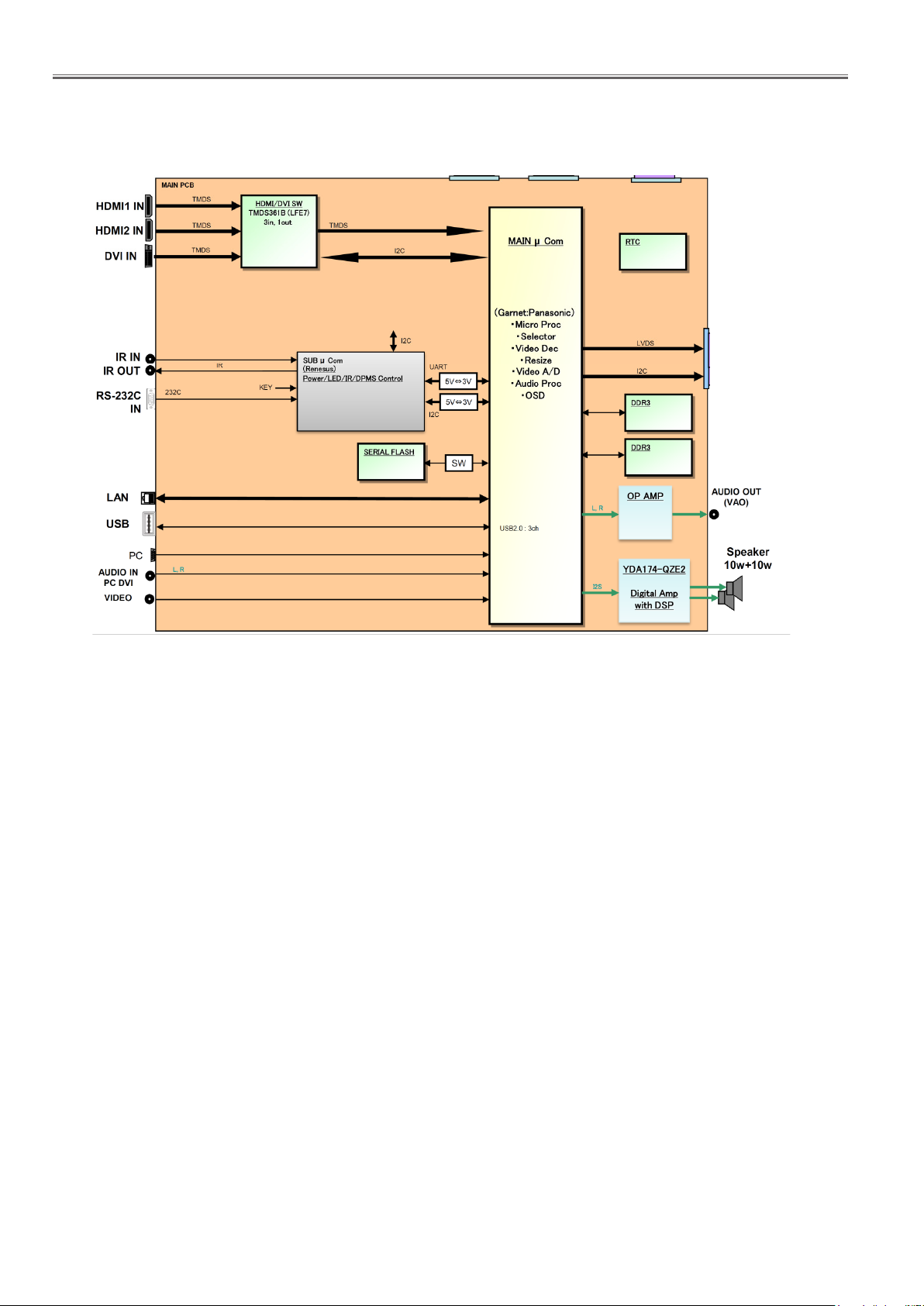
SECTION 4 DIAGRAMS
8 Block Diagram
Main Board
1. Block Diagrams
1.1. A module
<65LFE8>
DIA-2
Page 51
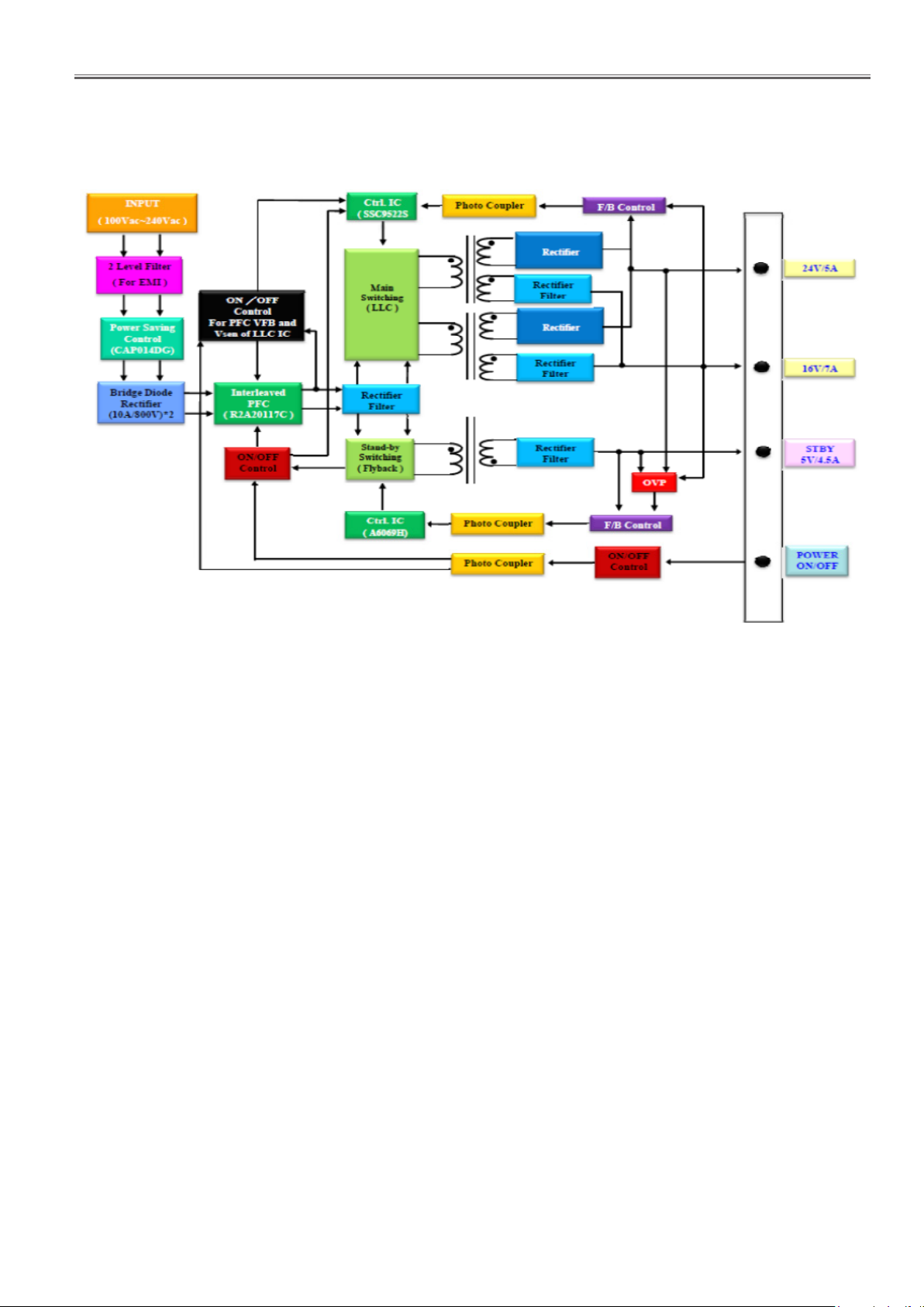
SECTION 4 DIAGRAMS
1.2. P module
<65LFE8>
DIA-3
Page 52

SECTION 4 DIAGRAMS
<65LFE8>
DIA-4
Page 53
SECTION 5 PARTS LIST
Exploded Views & Parts List
Model No. TH-65LFE8U
TH-65LFE8W
TH-65LFE8E
CONTENTS
SECTION 5 PARTS LIST
1. Exploded views .......................................... SPL-2
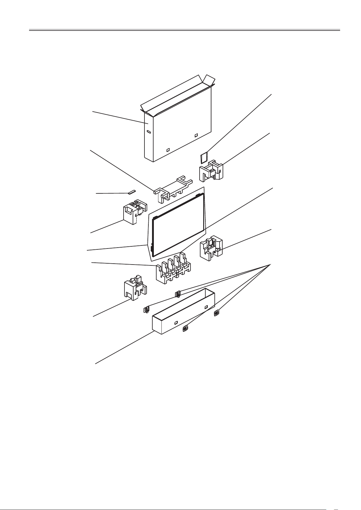
1. 1. Mechanical and electrical parts
1. 2. Packing
2. Replacement Parts List .................................... SPL-4
<65LFE8>
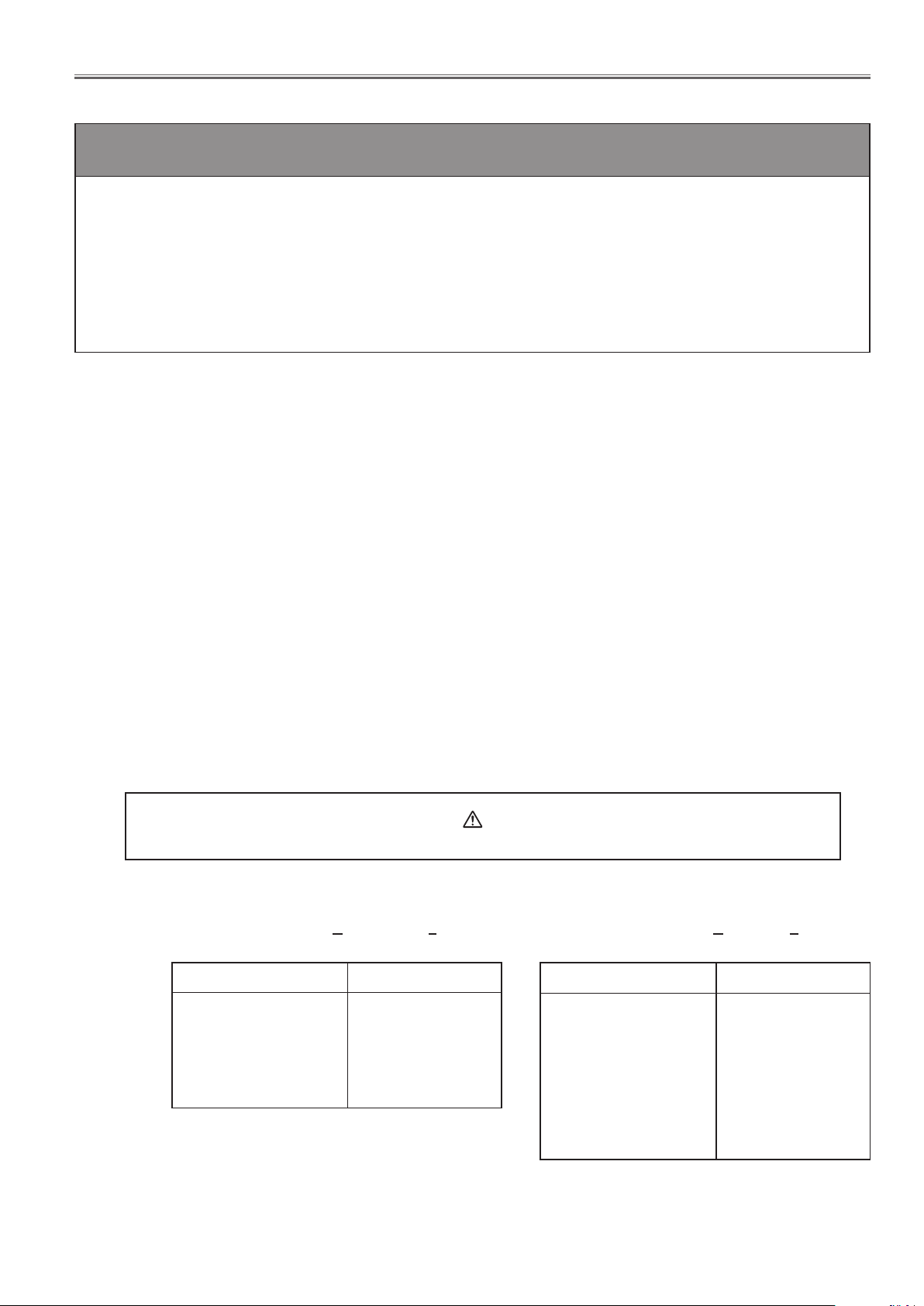
Components identied by the international symbol have special characteristics important for safety.
When replacing any of these components, use only the manufacturer's specied ones.
■Abbreviation of part name and description
1. Resistor
Example :
C : Carbon
F : Fuse
M : Metal Oxide
Metal Film
S : Solid
W : Wire Wound
■Note
:
Printed circuit board assembly with mark (RTL) is no longer available after production discontinuation of the complete set.
ERD25TJ104 C 100KOHM, J , 1/4W
TYPE
TYPE ALLOWANCE
F : ±1%
G : ±2%
J : ±5%
K : ±10%
M : ±20%
ALLOWANCE
2. Capacitor
Example :
SPL-1
ECKF1H103ZF C 0. 01PF, Z , 50V
TYPE ALLOWANCE
C : Ceramic
E : Electrolytic
P : Polyester
PP :Polypropylene
S : Poly styrol
T : Tantalum
TYPE
C : ± 0.25 pF
D : ± 0.5 pF
F : ± 1 pF
J : ± 5 %
K : ± 10 %
L : ± 15 %
M : ± 20 %
P : + 100 %, - 0 %
Z : + 80 %, - 20 %
ALLOWANCE
Page 54
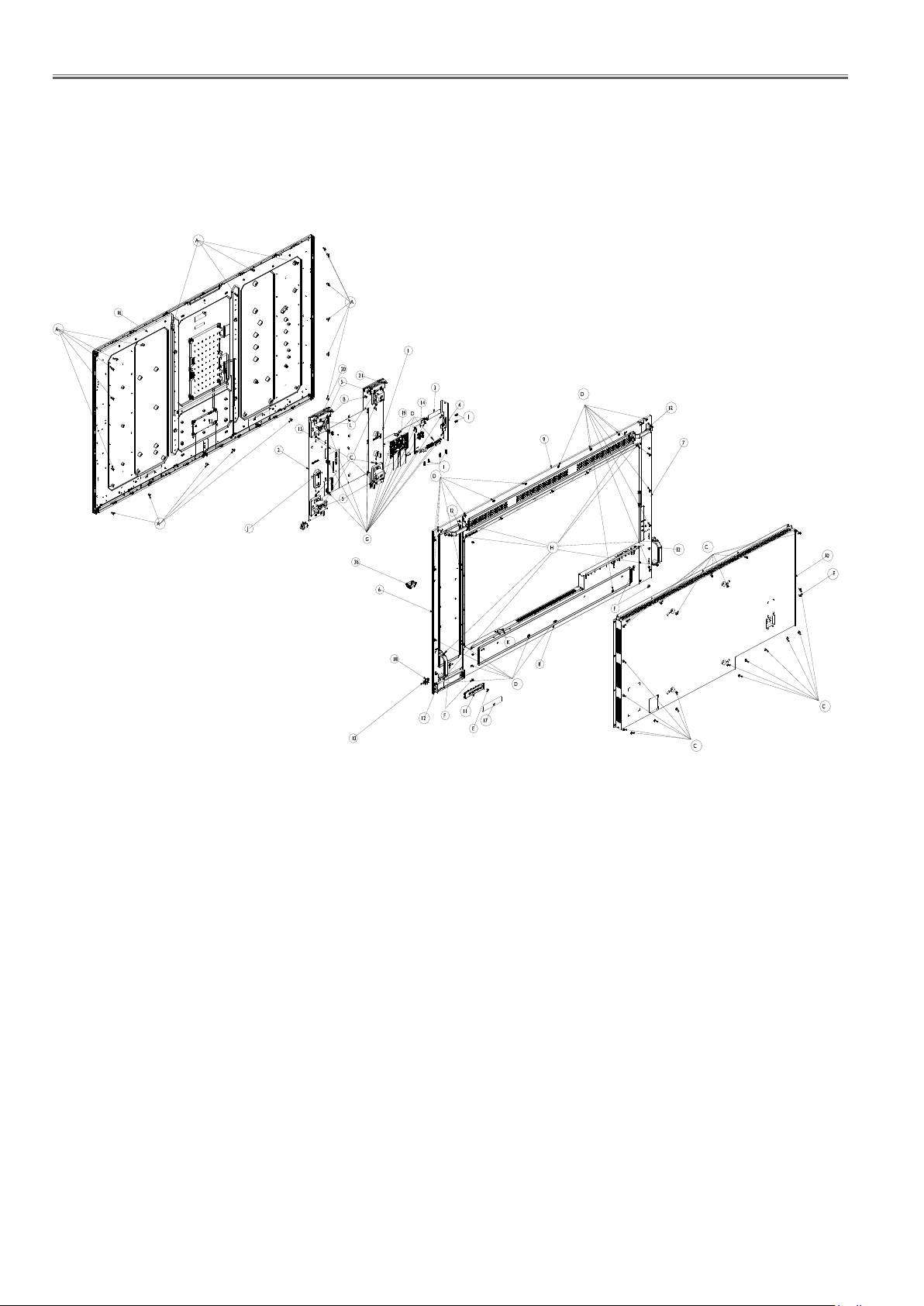
SECTION 5 PARTS LIST
1. Exploded views
1. 1. Mechanical and electrical parts
<65LFE8>
SPL-2
Page 55
SECTION 5 PARTS LIST
1. 2. Packing
22
24
<65LFE8>
23
25
28
26
29
34
27
31
33
30
32
SPL-3
Page 56
SECTION 5 PARTS LIST
2. Replacement Parts List
TH-65LFE8U/W/E
Safety Ref.No. Part No. Part Name & Description Pcs Remarks
(
2. Replacement Parts List
1 TZSH03131 POWER BOARD BRACKET R 1
2 TZSH03132 BRACKET MID 1
3 TZSH03133 MAIN PCB BRACKET BTM 1
4 TZSH03134 IO-BRACKET 1
5 TZSH03135 VESA BRACKET 4
6 DPVF1345ZA REAR COVER R 1
7 DPVF1346ZA REAR COVER L 1
8 TZSH03138 REAR COVER BTM 1
9 DPVF1347ZA REAR COVER TOP 1
10 TZSH03140 REAR COVER MID 1
11 TZSH03023 FUNCTION KEY BUTTON 1
12 TZSH03141 HANDLE 4
13 TZSH03022 IR WINDOW 1
14 DPVF1348ZA MAIN BOARD 1
15 TZSH03143 POWER BOARD 1
16 DPVF1433ZA LCD PANEL ASSY 1
17 TZZ00000690A KEY BOARD 1
18 TZSH03037 IR BOARD 1
19 TZZ00001217A FRC BOARD 1
20 TZSH03145 SPEAKER 1
21 TZSH03146 SPEAKER 1
22 TZSH03148 CARTON U 1 U
22 TZSH03150 CARTON W and E 1 W/E
<65LFE8>
23 TZSH03110 MANUAL LFE8 (ENG/SPA/FRE SIMPLE VERSION) 1 U/E
23 TZSH03111 MANUAL LFE8 (ARABIC SIMPLE VERSION) 1 W
23 TZSH03113 MANUAL LFE8 (ENGLISH FULL VERSION) 1 W
23 TZSH03112
TZSH03200 CD MANUAL LFE8 (ENG/ESP/FRE) 1 U model only
TZSH03061 CD MANUAL (LFE8E 7LANGUAGES) 1 E modei only
23 TZSH03166 COVER CABLE 1
24 DPVF1350ZA CUSHION-TM 1
25 DPVF1351ZA CUSHION-TL 1
26 DPVF1352ZA CUSHION-TR 1
28 DPVF1353ZA PROTECT BAG 1
29 DPVF1354ZA CUSHION-BM 1
30 DPVF1355ZA CUSHION-BR 1
31 DPVF1356ZA CUSHION-BL 1
32 TZSH03163 CARTON BUTTOM 1
33 TZZ00001793A PACKAGE BUCKLE 4
34 N2QAYA000099 REMOTE CONTROL UNIT 1
35 TZSH03165 COVER CABLE 1
DPVF1349ZA RATING LABEL U 1 U
TZSH03154 RATING LABEL W 1 W
TZSH03155 RATING LABEL E 1 E
TZZ00000671A POWER CORD FOR US 1 U
TZZ00000710A POWER CORD FOR EU 1 W/E
TZZ00000724A POWER CORD FOR UK 1 W/E
TZZ00000722A POWER CORD FOR AUSTRALIA 1 W
MANUAL LFE8
8LANGUAGES SIMPLE VERSION)
1E
TZSH03058 PROTECT BAG 1
TZSH03059 WIRE CLAMPER 3
TZSH03164 WIRE CLAMPER 4
TZSH03167 IO LABEL 1
TZSH03168 IO LABEL 1
TZSH03169 IO LABEL 1
TZSH03170 IO LABEL 1
TZSH03171 INSULATING SHEET 1
TZSH03180 AC INLET ASSY 1
TZSH03172 CABLE 1 TC02-PANEL
TZSH03173 CABLE 1 TC01-PANEL
TZSH03174 CABLE 1 CN901-TC11
TZSH03175 CABLE 1 A10-CN201
TZSH03176 CABLE 1 A5-SPEAKER
SPL-4
Page 57
SECTION 5 PARTS LIST
TH-65LFE8U/W/E
Safety Ref.No. Part No. Part Name & Description Pcs Remarks
TZSH03177 CABLE 1 A13-CN001
TZSH03178 CABLE 1 A1-CN903
TZSH03179 CABLE 1 CN802-PANEL
TZSH03181 SCREW 21 A
TZSH03182 SCREW 2 B
TZZ00000668A SCREW 44 C
DPVF1314ZA SCREW 29 D
TZZ00001380A SCREW 2 E
DPVF1315ZA SCREW 4 F
TZZ00000669A SCREW 16 G
TZZ00001727A SCREW 8 H
TZZ00000693A SCREW 6 I
TZZ00001270A SCREW 2 J
TZSH03185 SCREW 2 K
TZSH03186 SCREW 2 L
<65LFE8>
SPL-5
Page 58

SECTION 5 PARTS LIST
<65LFE8>
SPL-6
 Loading...