

Panasonic th-47lfx60u, th-47lfx60 operating instructions
Operating Instructions (Details)
FULL HD LCD Display (for business use)
Model No.
TH-47LFX60U
TH-47LFX6NU
TH-47LFX60W
TH-47LFX6NW
English
h
Please read these instructions before operating your set
and retain them for future reference.

Dear Panasonic Customer
Welcome to the Panasonic family of customers. We hope that you will have many years of
enjoyment from your new LCD Display.
To obtain maximum benefit from your set, please read these Instructions before making
any adjustments, and retain them for future reference.
Retain your purchase receipt also, and note down the model number and serial number of
your set in the space provided on the rear cover of these instructions.
Visit our Panasonic Web Site http://panasonic.net
ii
Precautions for Installation
• Do not install by yourself. Please ask a installation professional or your dealer to install.
• This product corresponds to IP55
resistance of the product.
• Please note the dust and water resistance of this product does not guarantee damage or fault free.
CAUTION
This product corresponds to international standard IP rating (Ingress Protection) dust ingress protection level 5 and
water ingress protection level 5.
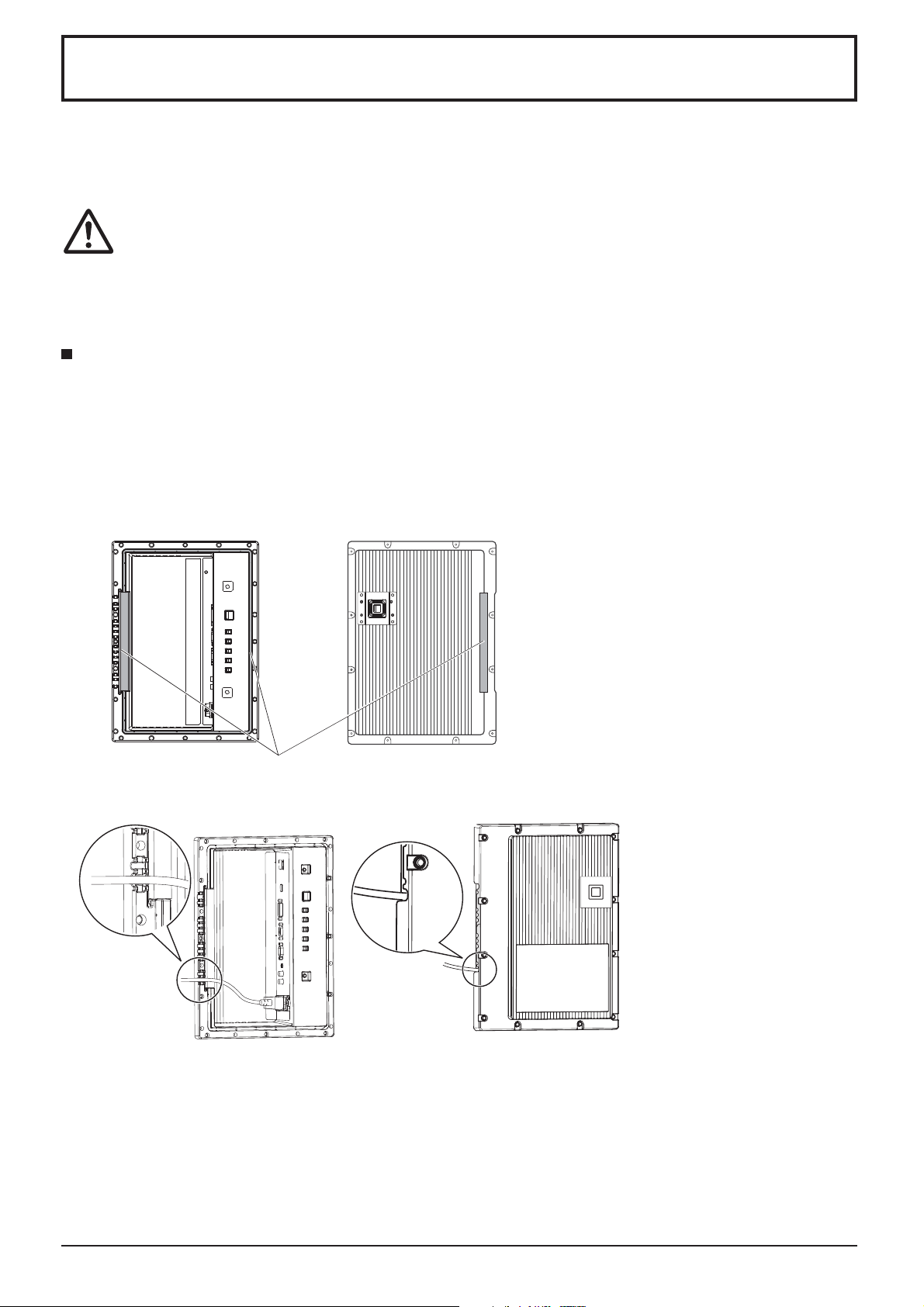
Terminal cover
After connecting cable etc. of the device to the terminals, check if the terminal cover is sealed correctly and closed
rmly using all the xing screws when attaching the terminal cover.
To seal the terminal cover correctly, be aware of the following points:
Check if the xing sealant is xed in the correct position in the cover. Fixing sealant is an important part to
seal the cable part.
Terminal part on main
unit rear side
*1
dust and water protection standard. Do not change or damage dust or water
Using with dust or water resistance degraded causes fire, electric shock, or
product damage.
Terminal cover rear side
Note:
IPX5 water resistance refers to the
capability to prevent the harmful effects
of water jet from any directions.
Fixing sealant
Stick the cable to the shape of the dent on the terminal strip base tightly.
*1: Based on tests performed by Cosmos Corporation.
The structure is to keep the
•
airtightness by tucking the cable
pulled out along the dent on the
terminal strip base with both fixing
sealant of the terminal strip base
and terminal cover.
iii
Precautions for Installation
Protective coating
Cabinet aluminum parts and rear face are protected from corrosion with coating. Be careful not to damage
the surface. In case the surface is damaged, corrosion may occur from there.
Installation position
•
When direct sunlight is on the screen, black shadow may appear. This will disappear when the temperature drops.
• To install the product long term in a special environment such as near a swimming pool, hot spring, or ocean, or in
a factory uses chemicals or gases, please consult your local Panasonic dealer beforehand.
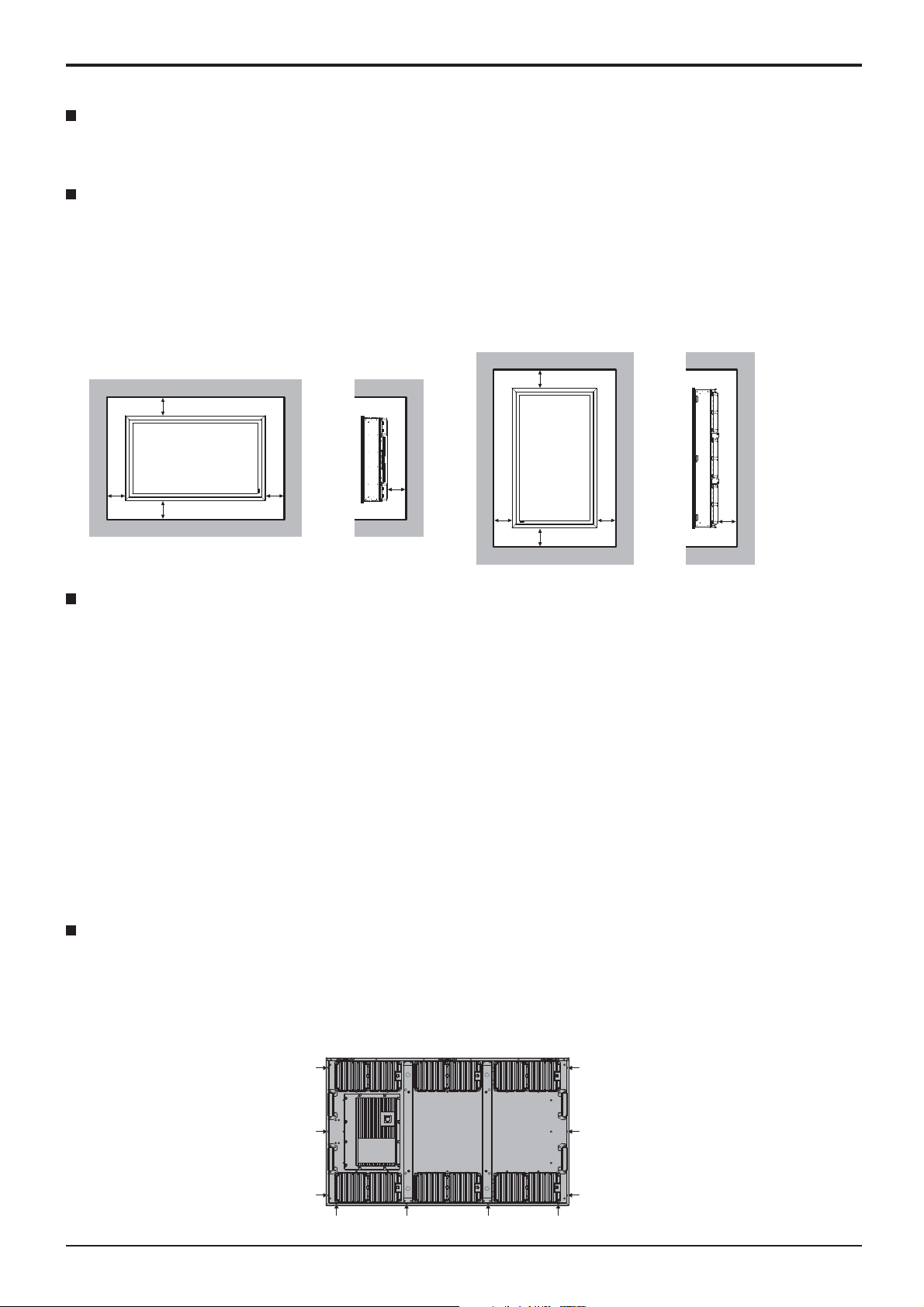
• The product is equipped with cooling fans and air lters that need to be cleaned or replaced if covered with dust.
Removing or installing air lters requires space around the Display. With this in mind, provide adequate space
when installing the Display.
[Height 7.874”/200 mm or greater, Width 7.874”/200 mm or greater, Depth 7.874”/200 mm or greater]
d
d
d
d:7.874”/200 mm or greater
Installation conditions
To use the product in an environment where outdoor air temperature is lower than 32 °F (0 °C), make sure to
set the “Outdoor mode” to “On”. The inside temperature is kept constant and the startup can be performed
smoothly. (see page 17, 33)
Consult your dealer if this product will be exhibited or used in a condition where it will be splashed with water
continuously or for a long time.
Always use the product at an ambient temperature in the range of 32 °F - 122 °F / 0 °C - 50 °C (during Outdoor
mode: -4 °F - 122 °F / -20 °C - 50 °C).
Ambient temperature refers to the temperature of the air immediately in front of the inlets on the back of the
Display.
Set Outdoor mode to “On” if the Display is installed where direct sunlight is on the screen.
The Display can be tilted forward or backward at an angle as high as 20 degrees.
To install on a wall etc.
d
d
d
d
d
d
d
• Consult your dealer about ttings etc. beforehand.
• In securing the back side of the Display to a wall, use VESA-based (400 x 400) ttings. Note that any VESA-based
ttings should not interfere with the screws (x 10) allowing the lter covers or terminal cover to be attached / removed
and the front door to be opened / closed (in the interest of operations by a service contractor).
iv

Precautions for Installation
• Choose a permanent position where the total weight of the product and ttings can be hold permanently. If the
strength of the position is not suf cient, a serious accident such as fall may be caused.
• Do not install the product where a person can be hang or lean on, or a passer may collide into. Accident may be
caused.
• Take measures for tipping over and fall with an assumption of a tting or installation location failure.
• Installation strength may be degraded due to aging depends on the environment. Ask a installation professional to
inspect or repair regularly.
• When an abnormality or fault such as loose screw is detected, ask an installation professional or your dealer
immediately for repair.
• Panasonic will not be responsible for any damages from an accident such as defect of installation, improper use,
modi cation, or natural disaster.
v
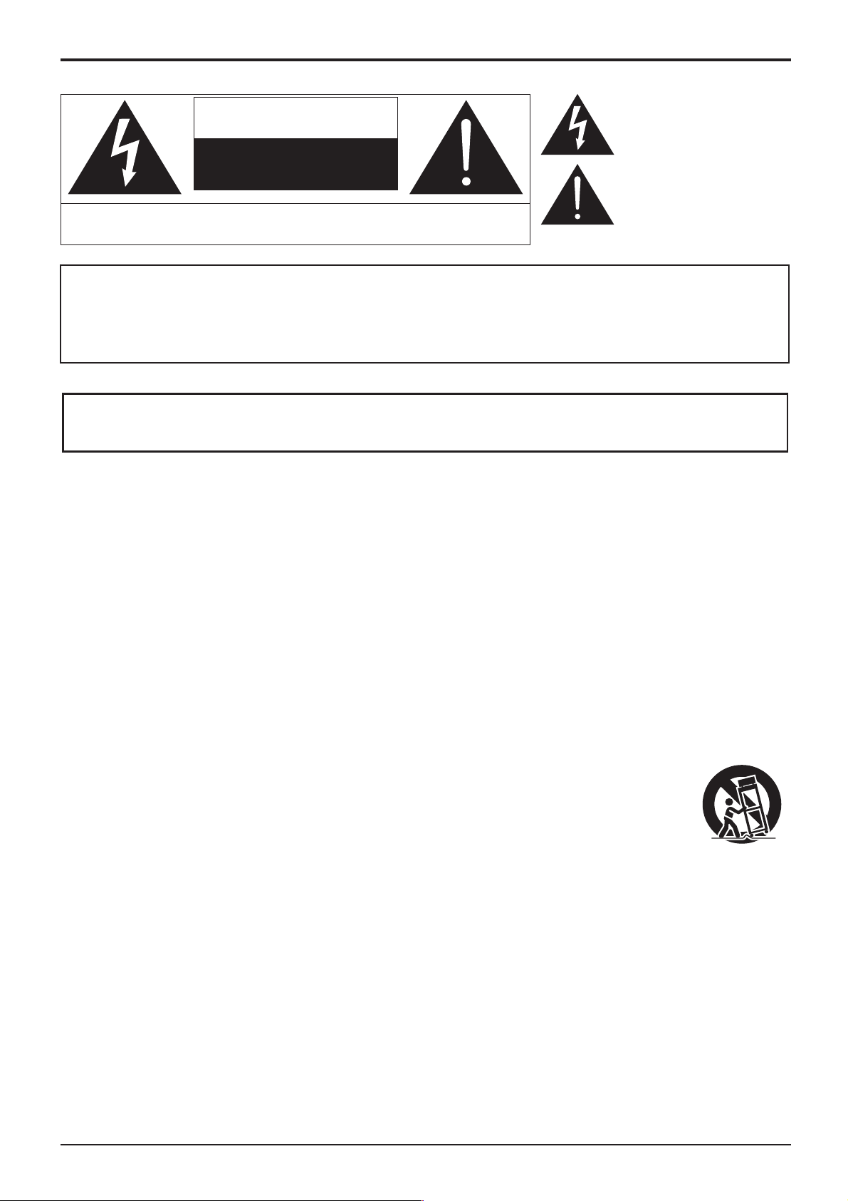
CAUTION
RISK OF ELECTRIC SHOCK
WARNING: To reduce the risk of electric shock, do not remove cover or back.
No user-serviceable parts inside. Refer servicing to qualified service personnel.
DO NOT OPEN
The lightning flash with arrowhead
within a triangle is intended to tell the
user that parts inside the product are a
risk of electric shock to persons.
The exclamation point within a
triangle is intended to tell the
user that important operating and
servicing instructions are in the
papers with the appliance.
WARNING :
2) Do not remove the grounding pin on the power plug. This apparatus is equipped with a three
1) To prevent electric shock, do not remove cover. No user serviceable parts inside. Refer
servicing to quali ed service personnel.
pin grounding-type power plug. This plug will only t a grounding-type power outlet. This is a
safety fea ture. If you are unable to insert the plug into the outlet, contact an electrician.
Important Safety Instructions
1) Read these instructions.
2) Keep these instructions.
3) Heed all warnings.
4) Follow all instructions.
5) Clean only with dry cloth.
6) Do not block any ventilation openings. Install in accordance with the manufacturer’s instructions.
7) Do not install near any heat sources such as radiators, heat registers, stoves, or other apparatus (including
ampli ers) that produce heat.
8) Do not defeat the safety purpose of the polarized or grounding-type plug. A polarized plug has two blades with
one wider than the other. A grounding type plug has two blades and a third grounding prong. The wide blade
or the third prong are provided for your safety. If the provided plug does not t into your outlet, consult an
electrician for replacement of the obsolete outlet.
9) Protect the power cord from being walked on or pinched particularly at plugs, convenience receptacles, and
the point where they exit from the apparatus.
10) Only use attachments / accessories speci ed by the manufacturer.
11) Use only with the cart, stand, tripod, bracket, or table speci ed by the manufacturer, or sold
with the apparatus. When a cart is used, use caution when moving the cart / apparatus
combination to avoid injury from tip-over.
12) Unplug this apparatus during lightning storms or when unused for long periods of time.
13) Refer all servicing to quali ed service personnel. Servicing is required when the apparatus
has been damaged in any way, such as power-supply cord or plug is damaged, liquid has been spilled or
objects have fallen into the apparatus, the apparatus has been exposed to rain or moisture, does not operate
normally, or has been dropped.
14) To prevent electric shock, ensure the grounding pin on the AC cord power plug is securely connected.
vi
FCC STATEMENT
This equipment has been tested and found to comply with the limits for a Class B digital device, pursuant to Part
15 of the FCC Rules. These limits are designed to provide reasonable protection against harmful interference
in a residential installation. This equipment generates, uses and can radiate radio frequency energy and, if not
installed and used in accordance with the instructions, may cause harmful interference to radio communications.
However, there is no guarantee that interference will not occur in a particular installation. If this equipment does
cause harmful interference to radio or television reception, which can be determined by turning the equipment
off and on, the user is encouraged to try to correct the interference by one or more of the following measures:
• Reorient or relocate the receiving antenna.
• Increase the separation between the equipment and receiver.
• Connect the equipment into an outlet on a circuit different from that to which the receiver is connected.
• Consult the dealer or an experienced technician for help.
This device complies with Part15 of the FCC Rules. Operation is subject to the following two conditions:(1) This
device may not cause harmful interference, and (2) this device must accept any interference received, including
interference that may cause undesired operation.
FCC CAUTION:
To assure continued compliance, follow the attached installation instructions and use only shielded
interface cables when connecting to computer or peripheral devices. Any changes or modi cations not
expressly approved by Panasonic Corp. of North America could void the user's authority to operate this
device.
FCC Declaration of Conformity
Model No. TH-47LFX60U, TH-47LFX6NU
Responsible Party: Panasonic Corporation of North America
Two Riverfront Plaza, Newark, New Jersey 07102-5490
Contact Source: Panasonic System Communications Company of North America
1-877-655-2357
CANADIAN NOTICE:
This Class B digital apparatus complies with Canadian ICES-003.
vii
Important Safety Notice
IMPORTANT: THE MOULDED PLUG (For TH-47LFX60W and TH-47LFX6NW)
WARNING
1) No naked ame sources, such as lighted candles, should be placed on / above the set.
2) To prevent electric shock, do not remove cover. No user serviceable parts inside. Refer servicing to quali ed
service personnel.
3) Do not remove the earthing pin on the power plug. This apparatus is equipped with a three pin earthing-type
power plug. This plug will only t an earthing-type power outlet. This is a safety feature. If you are unable to
insert the plug into the outlet, contact an electrician.
Do not defeat the purpose of the earthing plug.
4) To prevent electric shock, ensure the earthing pin on the AC cord power plug is securely connected.
CAUTION
This appliance is intended for use in environments which are relatively free of electromagnetic elds.
Using this appliance near sources of strong electromagnetic elds or where electrical noise may overlap with the
input signals could cause the picture and sound to wobble or cause interference such as noise to appear.
To avoid the possibility of harm to this appliance, keep it away from sources of strong electromagnetic elds.
FOR YOUR SAFETY, PLEASE READ THE FOLLOWING TEXT CAREFULLY.
This display is supplied with a moulded three pin mains plug for your safety and convenience. A 10 amp fuse is
tted in this plug. Shall the fuse need to be replaced, please ensure that the replacement fuse has a rating of 10
amps and that it is approved by ASTA or BSI to BS1362.
Check for the ASTA mark
If the plug contains a removable fuse cover, you must ensure that it is re tted when the fuse is replaced.
If you lose the fuse cover the plug must not be used until a replacement cover is obtained.
A replacement fuse cover can be purchased from your local Panasonic dealer.
Do not cut off the mains plug.
Do not use any other type of mains lead except the one supplied with this display.
The supplied mains lead and moulded plug are designed to be used with this display to
avoid interference and for your safety.
If the socket outlet in your home is not suitable, get it changed by a quali ed electrician.
If the plug or mains lead becomes damaged, purchase a replacement from an authorized
dealer.
WARNING : — THIS DISPLAY MUST BE EARTHED.
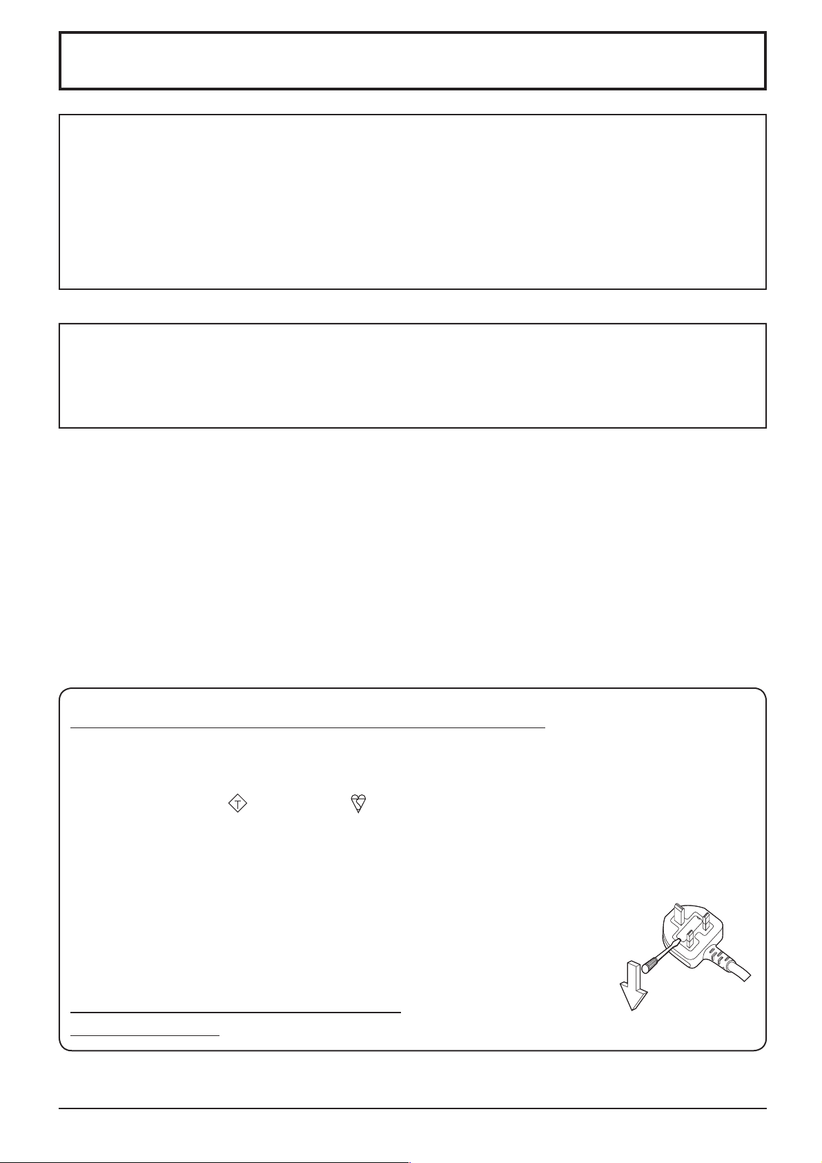
How to replace the fuse.
IMPORTANT: THE MOULDED PLUG (For TH-47LFX60W and TH-47LFX6NW)
or the BSI mark on the body of the fuse.
ASA
Open the fuse compartment with a screwdriver and replace the fuse.
viii

Table of Contents
Precautions for Installation .................................... iii
Important Safety Instructions ................................. vi
FCC STATEMENT .................................................... vii
Important Safety Notice ........................................ viii
Safety Precautions ................................................... 2
Accessories .............................................................. 6
Accessories Supply ................................................. 6
Remote Control Batteries ........................................ 7
About Power Supply Cord ....................................... 8
Connections .............................................................. 9
How to remove terminal cover ................................. 9
AC cord connection ................................................. 9
Video equipment connection ................................. 10
AUDIO OUT connection .........................................11
HDMI connection ....................................................11
DVI-D IN connection .............................................. 12
PC Input Terminals connection .............................. 13
SERIAL Terminals connection ............................... 14
Example connection using the DIGITAL LINK
Terminal ................................................................. 15
Power On / Off ......................................................... 16
Selecting the input signal ...................................... 18
Basic Controls ........................................................ 19
ASPECT Controls ................................................... 21
Digital Zoom ............................................................ 22
On-Screen Menu Displays ..................................... 23
Adjusting Pos. /Size ............................................... 24
Picture Adjustments ............................................... 26
Advanced settings ................................................. 27
Sound Adjustment .................................................. 28
PRESENT TIME Setup / Set up TIMER .................. 29
PRESENT TIME Setup .......................................... 29
Set up TIMER ........................................................ 30
Screensaver (For preventing image retention) .... 31
Setup of Screensaver Time ................................... 32
Wobbling ................................................................. 32
No activity power off .............................................. 33
Outdoor mode ......................................................... 33
ECO Mode settings ................................................. 34
Customizing the Input labels ................................. 35
Selecting the On-Screen Menu Language ............ 36
Customizing the On-Screen Menu Display .......... 36
Setup for MULTI DISPLAY ...................................... 37
How to Setup MULTI DISPLAY ............................. 37
ID Remote Control Function .................................. 38
Setup for Input Signals .......................................... 39
YUV / RGB-in select .............................................. 39
Signal menu .......................................................... 39
Cinema reality* ...................................................... 40
XGA Mode ............................................................. 40
Sync ...................................................................... 40
HDMI Range .......................................................... 41
Input signal display ................................................ 41
Maintenance information ....................................... 42
Network Setup ........................................................ 43
Options Adjustments ............................................. 46
Input Search .......................................................... 48
RS-232C/LAN Information Timing ......................... 49
Using Network Function ........................................ 50
Network Connection .............................................. 50
DIGITAL LINK Connections (connecting with a
twisted pair cable transmitter) ............................... 51
Command Control ................................................. 52
PJLink™ Protocol .................................................. 52
Using Web Browser Control .................................. 53
Before Using Web Browser Control....................... 53
Access from Web Browser .................................... 53
Display Control (BASIC CONTROL/OPTION
CONTROL Screen) ............................................... 54
NETWORK SETTING (NETWORK SETTING
Screen) .................................................................. 55
Password Setting (CHANGE PASSWORD
Screen) .................................................................. 55
Crestron Connected™ page .................................. 56
Troubleshooting ..................................................... 58
Applicable Input Signals ........................................ 60
Shipping condition ................................................. 61
Speci cations ......................................................... 62
Trademark Credits
• VGA is a trademark of International Business Machines Corporation.
• Microsoft®, Windows®, Windows Vista®, and Internet Explorer® are the registered trademarks or trademarks of
Microsoft Corporation in the United States and/or other countries.
• Macintosh, Mac, Mac OS, OS X and Safari are the trademarks of Apple Inc. registered in the United States and
other countries.
• SVGA, XGA, SXGA and UXGA are registered trademarks of the Video Electronics Standard Association.
Even if no special notation has been made of company or product trademarks, these trademarks have been fully
respected.
• HDMI, the HDMI Logo, and High-De nition Multimedia Interface are trademarks or registered trademarks of HDMI
Licensing LLC in the United States and other countries.
• RoomView, Crestron RoomView and Fusion RV are registered trademarks of Crestron Electronics, Inc, and
Crestron Connected is the trademark of Crestron Electronics, Inc.
Note:
Image retention may occur. If you display a still picture for an extended period, the image might remain on the screen.
However, it will disappear after a while.
1
Safety Precautions
WARNING
Setup
This LCD Display is for use only with the following optional accessories. Use with any other type of optional
accessories may cause instability which could result in the possibility of injury.
(All of the following accessories are manufactured by Panasonic Corporation.)
Replacement Air Filter .................................... TY-AF60STD (Air lter A: 6, Air lter B: 3, Air lter C: 3)
We are not responsible for any product damage, etc. caused by use of the wall-hanging bracket or ceiling-hanging
bracket other than those speci ed, or by failures in the installation environment for the wall-hanging bracket or ceilinghanging bracket even during the warranty period.
Always be sure to ask a quali ed technician to carry out set-up.
Small parts can present choking hazard if accidentally swallowed. Keep small parts away from young children. Discard
unneeded small parts and other objects, including packaging materials and plastic bags/sheets to prevent them from
being played with by young children, creating the potential risk of suffocation.
Do not place the Display on sloped or unstable surfaces, and ensure that the Display does not hang over the
edge of the base.
• The Display may fall off or tip over.
Do not place any objects on top of the Display.
• If any foreign objects get inside the Display, please consult your local Panasonic dealer.
Transport only in upright position!
• Transporting the unit with its display panel facing upright or downward may cause damage to the internal
circuitry.
Ventilation should not be impeded by covering the ventilation openings with items such as newspapers, table
cloths and curtains.
For suf cient heat release;
Leave a space of 7.874” (20 cm) or more at the top, bottom, right, left, and rear to install.
• Use the product within the operating condition temperature range.
• Do not block any inlet or outlet of the Display.
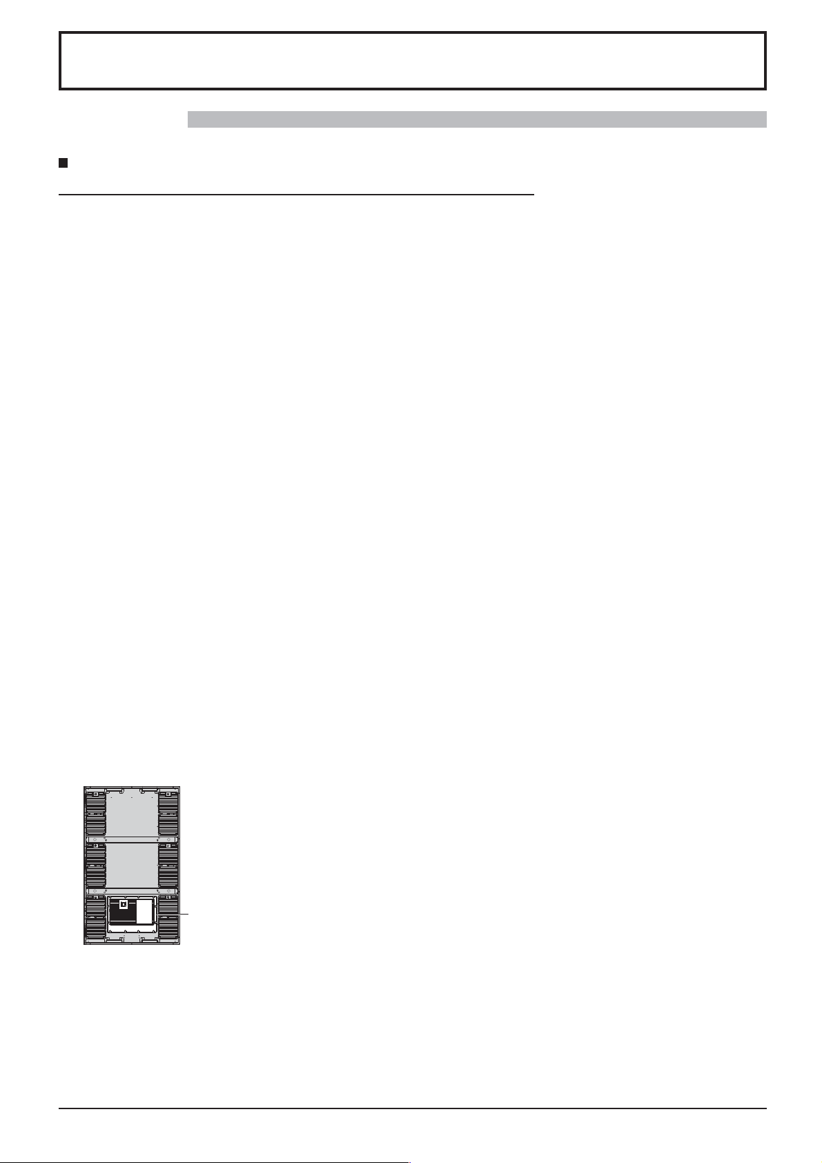
Cautions for Wall Installation
• Wall installation should be performed by an installation professional. Installing the Display incorrectly may lead to
an accident that results in death or serious injury. Furthermore, when installing on a wall, a wall hanging bracket
that conforms to VESA standards (VESA 400 × 400) must be used.
• When installing the Display vertically, make sure to place the terminal cover downward.
terminal cover
• If you terminate the use of the Display on the wall, ask a professional to remove the Display as soon as possible.
Install the Display away from any heaters.
• This causes cabinet deformation and breakdown.
2

Safety Precautions
When using the LCD Display
The Display is designed to operate on 110 - 127 or 220 - 240 V AC, 50/60 Hz.
Attach the terminal cover rmly to use.
• Otherwise the dust and water resistance is damaged and may cause re, electric shock or product damage.
Do not stick any foreign objects into the Display.
• Do not insert any metal or ammable objects into the Display or drop them onto the Display, as doing so can cause
re or electric shock.
Do not remove the cover or modify it in any way.
• High voltages which can cause severe electric shocks are present inside the Display. For any inspection, adjustment
and repair work, please contact your local Panasonic dealer.
Ensure that the mains plug is easily accessible.
An apparatus with CLASS I construction shall be connected to a mains socket outlet with a protective earthing connection.
Do not use any power supply cord other than that provided with this unit.
• Doing so may cause re or electric shocks.
Securely insert the power supply plug as far as it will go.
• If the plug is not fully inserted, heat may be generated which could cause re. If the plug is damaged or the wall
socket is loose, they shall not be used.
Do not handle the power supply plug with wet hands.
• Doing so may cause electric shocks.
Do not do anything that may damage the power cable. When disconnecting the power cable, pull on the plug body, not the cable.
• Do not damage the cable, make any modi cations to it, place heavy objects on top of it, heat it, place it near any
hot objects, twist it, bend it excessively or pull it. To do so may cause re and electric shock. If the power cable is
damaged, have it repaired at your local Panasonic dealer.
Keep the accessories screw out of reach of children to prevent swallowing.
If the Display is not going to be used for any prolonged length of time, unplug the power supply plug from
the wall outlet.
To prevent the spread of re, keep candles or other open ames away from this product at all times.
If problems occur during use
If a problem occurs (such as no picture or no sound), or if smoke or an abnormal odour starts to come out
from the Display, immediately unplug the power supply plug from the wall outlet.
• If you continue to use the Display in this condition, re or electric shock could result. After checking that the smoke
has stopped, contact your local Panasonic dealer so that the necessary repairs can be made. Repairing the Display
yourself is extremely dangerous, and shall never be done.
If foreign objects get inside the Display, if the Display is dropped, or if the cabinet becomes damages, disconnect
the power supply plug immediately.
•
A short circuit may occur, which could cause re. Contact your local Panasonic dealer for any repairs that need to be made.
3

Safety Precautions
CAUTION
When using the LCD Display
Be sure to disconnect all cables before moving the Display.
• If the Display is moved while some of the cables are still connected, the cables may become damaged, and re or
electric shock could result.
Disconnect the power supply plug from the wall socket as a safety precaution before carrying out any
cleaning.
• Electric shocks can result if this is not done.
Clean the power cable regularly to prevent it becoming dusty.
• If dust built up on the power cord plug, the resultant humidity can damage the insulation, which could result in re.
Pull the power cord plug out from the wall outlet and wipe the mains lead with a dry cloth.
Do not burn or breakup batteries.
• Batteries must not be exposed to excessive heat such as sunshine, re or the like.
Power supply
• Install the product near an electrical outlet so that the plug can be unplugged immediately when an abnormality
occurs.
• For a wall installation, used a power outlet which can be unplugged immediately when an abnormality occurs.
• This product is energized when the power plug is inserted to a socket. To cut off the power completely, the power
plug must be unplugged from the socket.
Cabinet
• Corner part of the metal cabinet is a potential injury hazard.
• To lift the product, hold the handles for the precaution of fall. Injury or damage may be caused.
Do not touch the fans when replacing the air lters.
Cleaning and maintenance
About the glass surface
• If ngerprints or dirt are on the glass surface, clear image cannot be obtained. Please be careful not to scratch or
make it dirty.
Dirt on the glass can be cleaned with a sponge, cloth or squeegee. Do not use strong acidic or alkaline
solution, especially detergent contains uoride, otherwise the antire ection material on the glass surface will
be affected to have irreparable damage.
The glass has been specially treated. Wipe the glass gently using only a cleaning cloth or a soft, lint-free
cloth.
• If the glass is particularly dirty, wipe with a soft, lint-free cloth which has been soaked in pure water or water in
which neutral detergent has been diluted 100 times, and then wipe it evenly with a dry cloth of the same type until
the surface is dry.
If the cabinet becomes dirty, wipe it with a soft, dry cloth.
• If the cabinet is particularly dirty, soak the cloth in water to which a small amount of neutral detergent has been
added and then wring the cloth dry. Use this cloth to wipe the cabinet, and then wipe it dry with a dry cloth.
• Do not allow any detergent to come into direct contact with the surface of the Display. If water droplets get inside
the unit, operating problems may result.
• Avoid contact with volatile substances such as insect sprays, solvents and thinner, otherwise the quality of the
cabinet surface may be adversely affected or the coating may peel off. Furthermore, do not leave it for long periods
in contact with articles made from rubber or PVC.
4
Safety Precautions
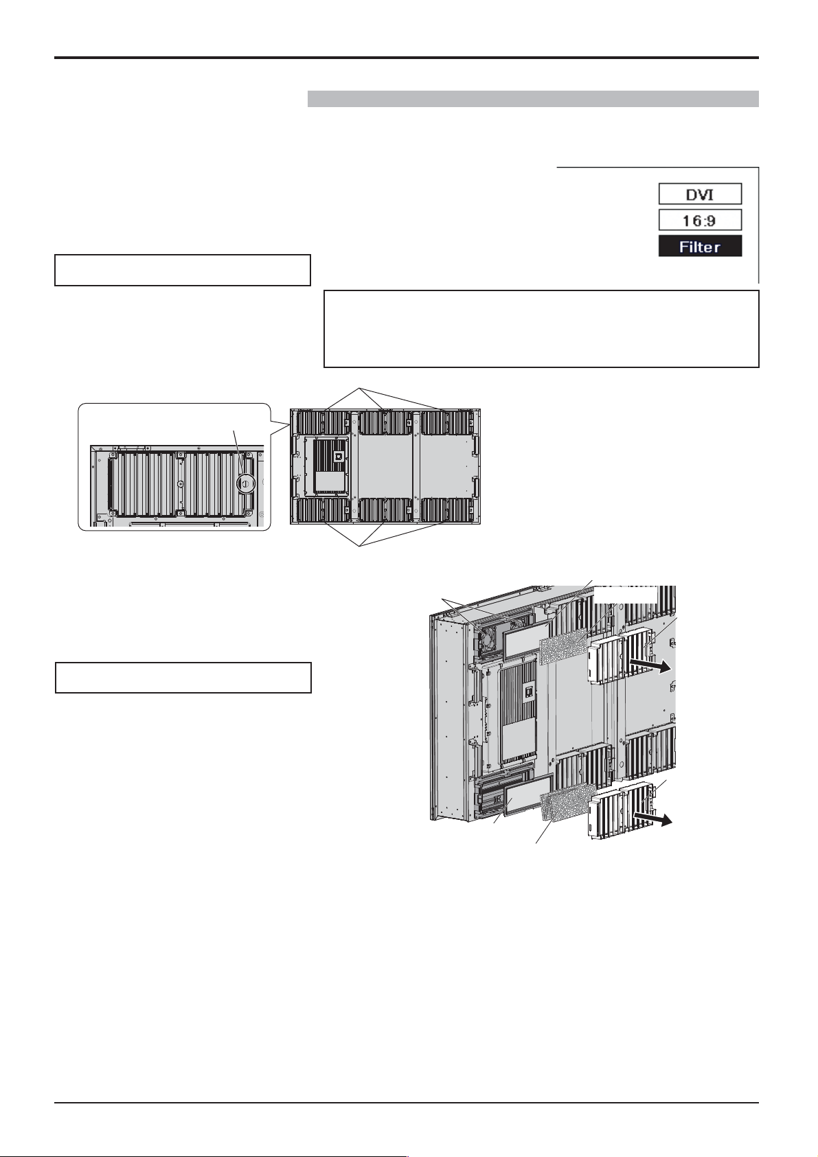
Maintaining air lters
The cooling structure of the Display is designed to circulate air taken in from outside inside the Display using fans. Air
lters are built into the inlet and outlet.
When “Filter” is displayed on the screen as you turn on the power, or when the
power indicator is blinking green and orange alternately, there is accumulated
dust on the air lters. Check the condition of the air lter and fan in “Maintenance
Information” in the Setup menu, and clean or replace the air lter and inspect the
fan as necessary. (see page 42)
How to remove the air lters
Unplug the power plug.
1
Loosen the decorative screws on
2
the exhaust vent sections until
they turn freely.
Decorative screw
Remove the lter cover, and pull
3
out the air lter B and air lter C.
Pull out the air lter A.
4
How to install the air lters
When replacing the air lters, carefully prevent foreign matter from
entering the inside of the Display.
If foreign matter has entered, do not try to take it out by force but
consult your local Panasonic dealer.
Outlet
Inlet
Fan
Do not touch the fans.
Air lter A
Air lter B
Filter Cover
Install the air lter A.
Install the air lter B to the outlet.
Fold the air lter C into thirds and install to the
inlet.
Make sure to install the air lters correctly.
Attach the lter covers and tighten the decorative
screws.
Check whether the lter covers are secure.
Air lter A
Air lter C (Folded into thirds)
Cleaning air lters
To clean the air lters, soak in a neutral detergent diluted 200 times with water, rinse well in water, and leave to
dry in the shade.
Notes:
• Air lters must be installed before using the Display. The absence of an air lter may cause failure in the
Display due to the intake of foreign matter or dust.
• When an air lter is damaged or is unobtrusively soiled even after cleaning, replace the air lter with a new
one. Contact your sales agent for replacement.
• The amount of foreign matter or dust adhering to air lters varies depending on the installation location and the
used hours. Increase the frequency of cleaning in locations where dust can easily accumulate.
• Do not touch the fans or wiring inside the Display.
• When removing air lters from or installing into the Display set on a high place, take care of your own safety,
and avoid the concerned parts falling.
• Clean the air lters approximately once every 1 month and replace them approximately once a year.
• There is no fan in the inlet.
Filter Cover
5
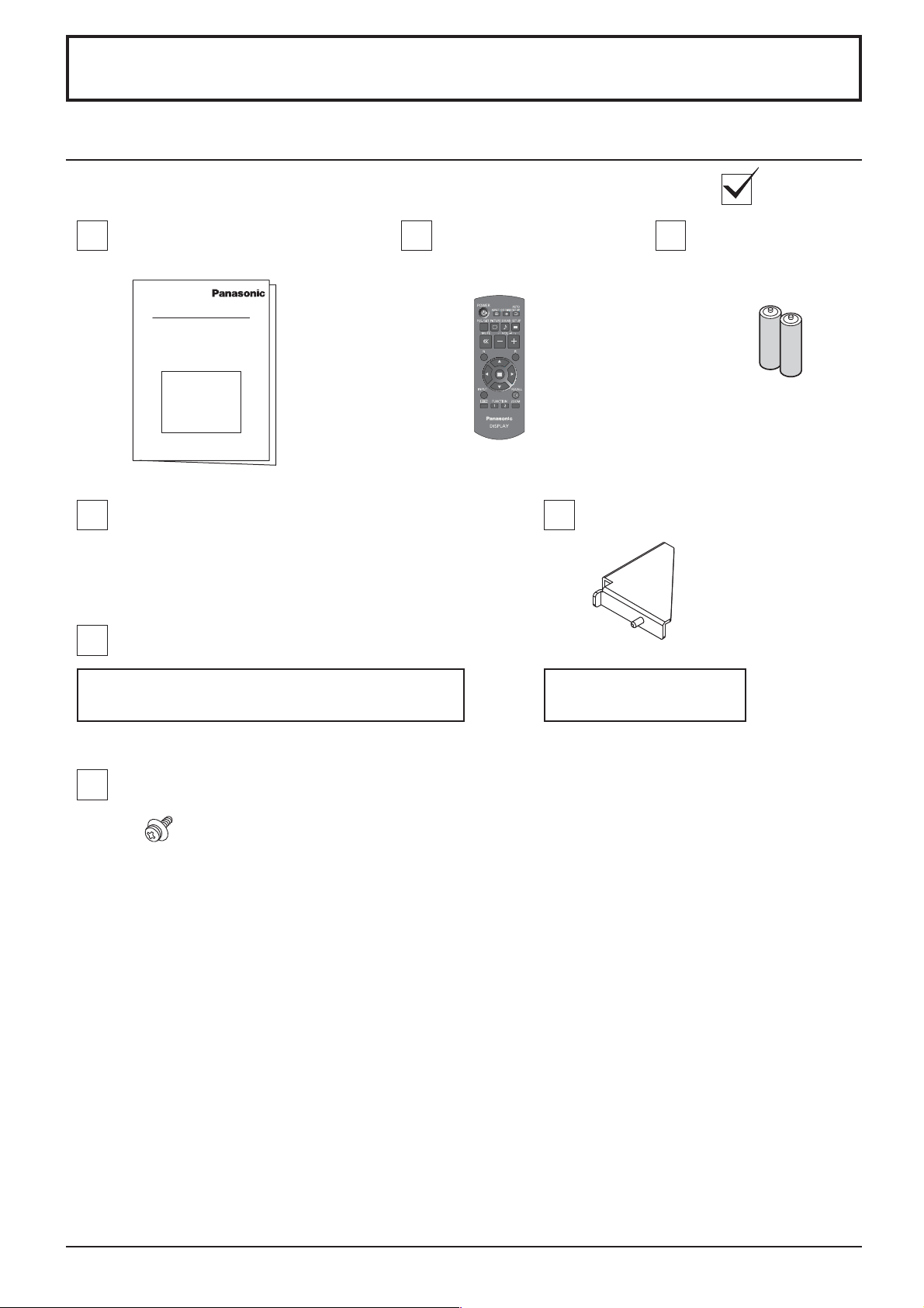
Accessories
Accessories Supply
Check that you have the accessories and items shown
Operating Instruction book
Power supply cord
Main plug types vary between countries. Make sure to
use the power supply cord with the voltage and shape
appropriate to your country and region. (see page 8)
Panasonic badge
Remote Control
Transmitter
N2QAYB000691
Batteries for the Remote
Control Transmitter
(R6 (UM3, AA) Size × 2)
Note:
Remote Control
Transmitter is not
water protection type.
Door holders × 2
An installation professional or service provider will
attach it to the Display frame at the time of installation.
Screws × 12
XYN4+F10VM
Attention
Store small parts in an appropriate manner, and keep them away from young children.
Used by a service provider
during maintenance work.
6
Accessories
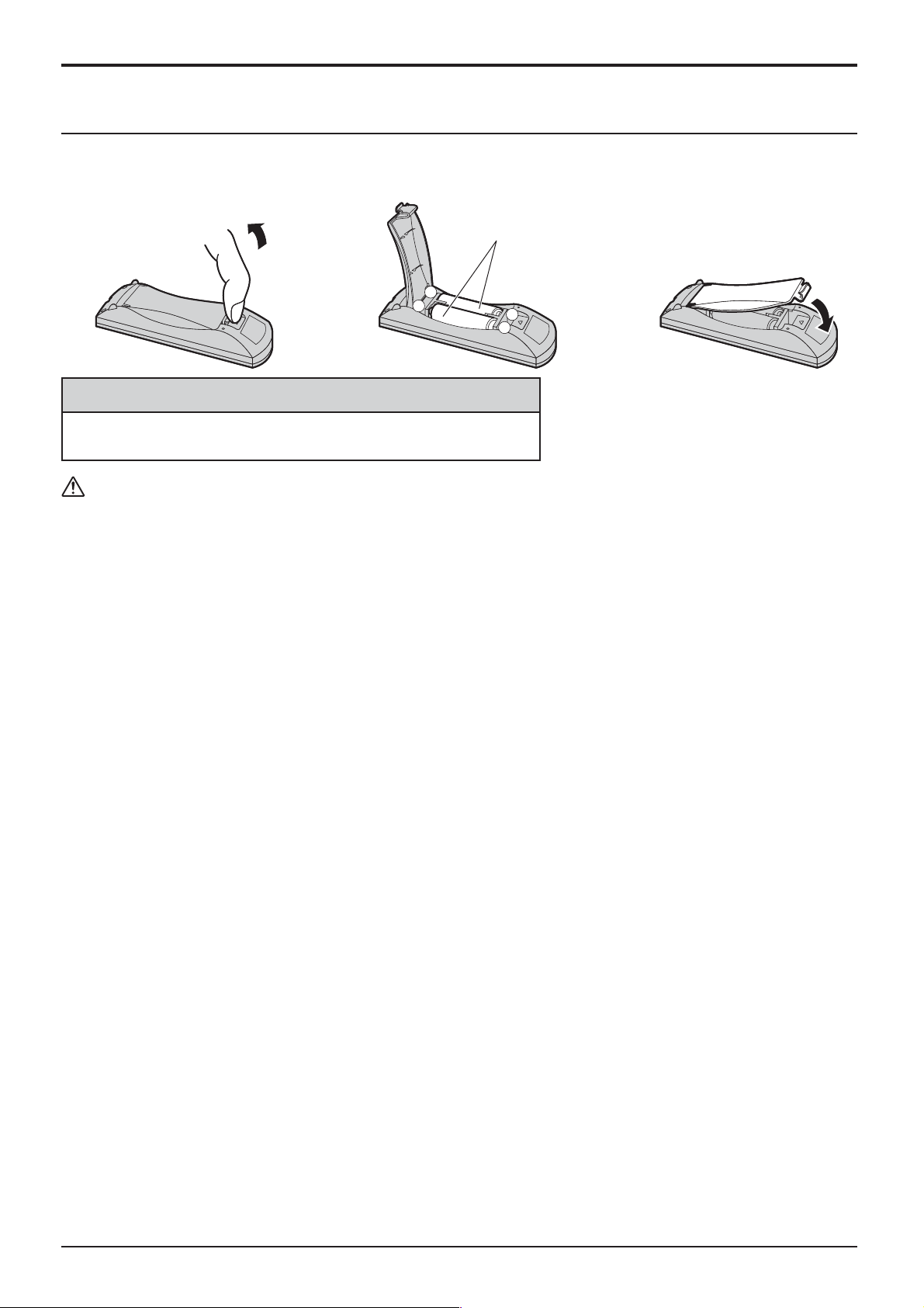
Remote Control Batteries
Requires two R6 batteries.
1. Pull and hold the hook, then open
the battery cover.
2. Insert batteries - note correct
polarity ( + and -).
“R6 (UM3, AA)” size
-
+
+
-
Helpful Hint:
For frequent remote control users, replace old batteries with Alkaline
batteries for longer life.
Precaution on battery use
Incorrect installation can cause battery leakage and corrosion that will damage the remote control transmitter.
Disposal of batteries should be in an environment-friendly manner.
Observe the following precaution:
1. Batteries shall always be replaced as a pair. Always use new batteries when replacing the old set.
2. Do not combine a used battery with a new one.
3. Do not mix battery types (example: “Zinc Carbon” with “Alkaline”).
4. Do not attempt to charge, short-circuit, disassemble, heat or burn used batteries.
5.
Battery replacement is necessary when remote control acts sporadically or stops operating the Display set.
6. Do not burn or breakup batteries.
Batteries must not be exposed to excessive heat such as sunshine, re or the like.
3. Replace the cover.
7
Accessories
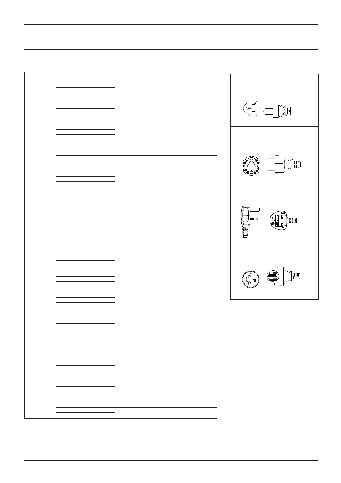
About Power Supply Cord
Main plug types vary between countries. Check the shape of the power plugs to choose the appropriate cable for
you.
Country name and applicable model name Appropriate AC Cables
Asia
TH-47LFX60W
TH-47LFX6NW
Middle East
TH-47LFX60W
TH-47LFX6NW
Africa
TH-47LFX60W
TH-47LFX6NW
Middle/South America
TH-47LFX
TH-47LFX6NU
North America
TH-47LFX
TH-47LFX6NU
Europe
TH-47LFX60W
TH-47LFX6NW
Oceania
TH-47LFX60W
TH-47LFX6NW
India
Indonesia
Philippine
Malaysia
Singapore
Hong Kong
United Arab Emirates
Iraq
Iran
Oman
Syria
Lebanon
Qatar
Kuwait
Saudi Arabia
Egypt
South Africa
Uruguay
Ecuador
Colombia
Chili
Panama
60
U
Paraguay
Puerto Rico
Venezuela
Peru
Bolivia
Honduras
60
U
USA
Canada
Italy
Austria
Netherlands
Greece
Switzerland
Sweden
Spain
Czech
Denmark
Germany
Norway
Hungary
Finland
France
Bulgaria
Belgium
Portugal
Poland
Monaco
Luxembourg
Russia
Kazakhstan
Ukraine
Belarus
UK Cable C
Australia
New Zealand
Cable B or Cable C
Cable B or Cable C
Cable B or Cable CEthiopia
Cable A (110-127 V AC Compatible)
Cable C
Cable C
Cable A
Cable B
Cable D
TH-47LFX60U, TH-47LFX6NU:
Cable A
Plug Type : A
TH-47LFX60W, TH-47LFX6NW:
Cable B
Plug Type : SE
Cable C
Plug Type : BF
Cable D
Plug Type : O
Insulating sleeve
Note:
Note:
Depending on the country of destination,
Depending on the country of destination,
relay type or direct attached type of the
relay type or direct attached type of the
power supply cord is used.
power supply cord is used.
8
Connections
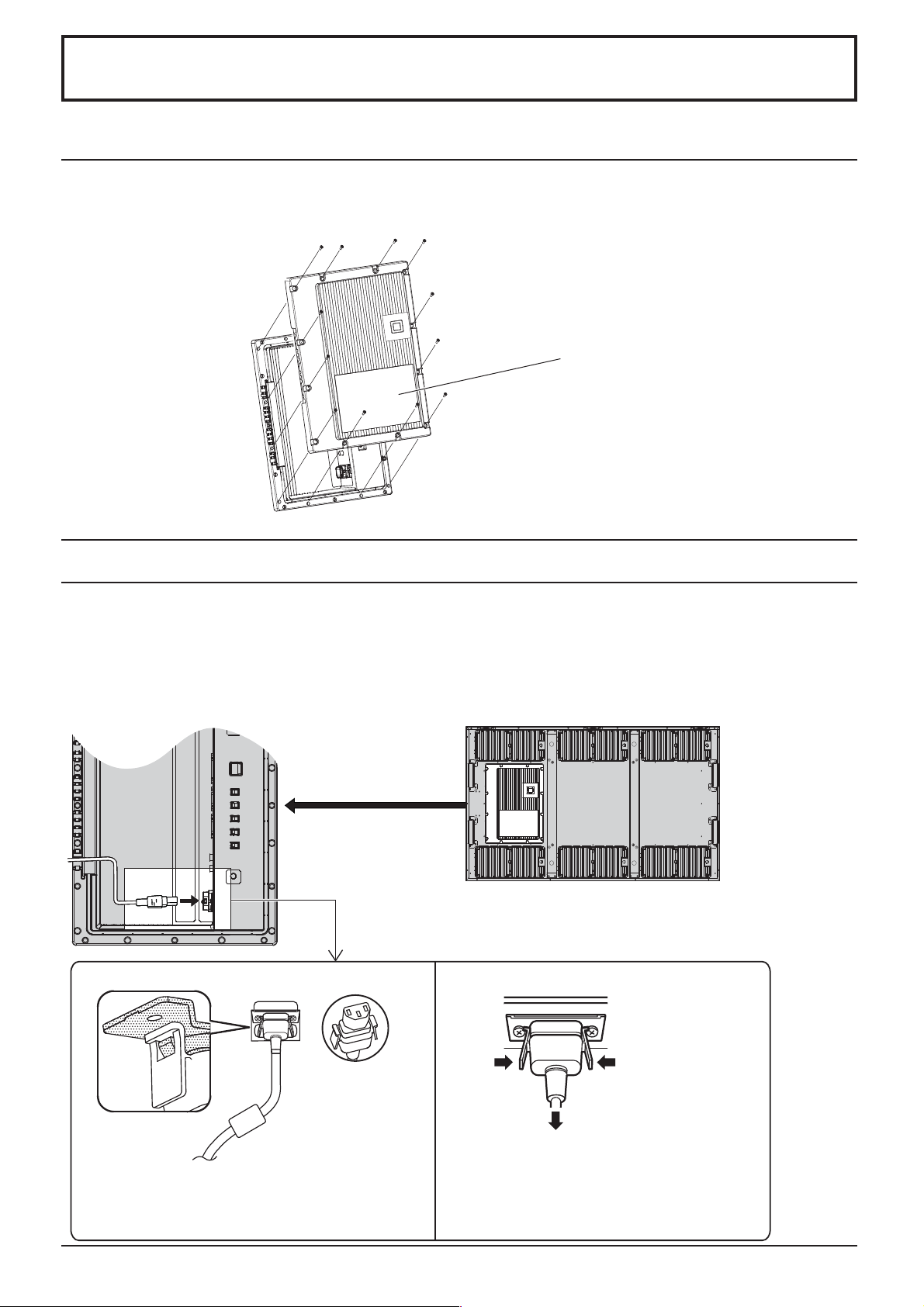
How to remove terminal cover
A terminal cover is attached to the input and output terminals to protect them from dust and water.
To remove the terminal cover to connect a cable or other item, remove all 12 screws from the terminal cover.
Opening the terminal cover with some screws left on will damage the terminal cover.
Remove the screws (12) to
take out the terminal cover.
AC cord connection
Notes:
• After connection, check the cable is pulled out along the groove without overlapping, then tighten the all 12 screws
to attach the terminal cover correctly. Otherwise water enters inside and causes re, electric shock and product
damage.
• Make sure to read the “Terminal cover” (page iii) section for the correct handling of the terminal cover to use the
product properly.
Remove the terminal
cover
(See above)
AC cord xing
Unplug the AC cord
Plug the AC cord into the display unit.
Plug the AC cord until it clicks.
Note:
Make sure that the AC cord is locked on both the left
and right sides.
Unplug the AC cord pressing the two knobs.
Note:
When disconnecting the AC cord, be absolutely
sure to disconnect the AC cord plug at the
socket outlet rst.
9
Connections
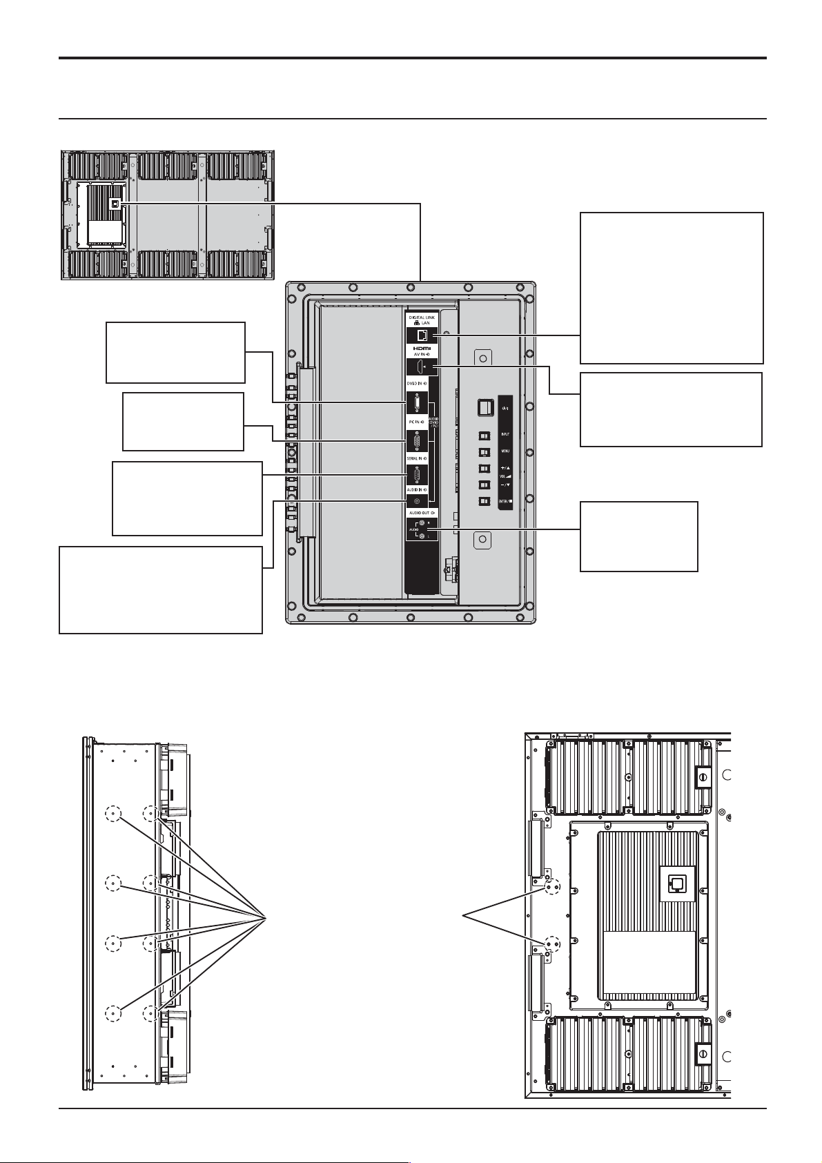
Video equipment connection
Remove the terminal cover
(see page 9)
DVI-D IN
DVI-D Input Terminal
(see page 12)
PC IN
PC Input Terminal
(see page 13)
LAN, DIGITAL LINK*
Connect to a DIGITAL LINK
input terminal network
to control the Display.
Alternatively, connect to
a device that sends video
and audio signals via the
DIGITAL LINK terminal.
(see page 15)
AV IN
HDMI
HDMI Input Terminal
(see page 11)
SERIAL
Control the Display by
connecting to PC
(see page 14)
AUDIO (DVI-D / PC)
Connect the audio output of
equipment connected to DVI-D
IN or PC IN.
(see page 12, 13)
Note:
* DIGITAL LINK is technology that enables signals such as audio and video to be transmitted using twisted pair
cables. (see page 15, 51)
• Use the screw holes shown in the gures below for such purposes as mounting the brackets for cabling if necessary.
(Use the supplied screws for screw holes.)
AUDIO OUT
Connect to sound
equipment
(see page 11)
10
8 places
4 places
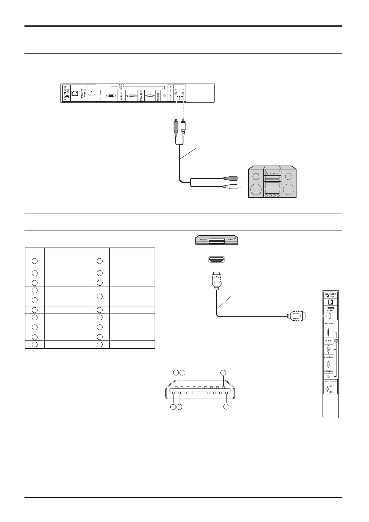
AUDIO OUT connection
Note:
Additional equipment and cables shown are not supplied with this set.
Stereophonic sound code
Connections
audio equipment
line-in
HDMI connection
[Pin assignments and signal names]
Pin No.
Signal Name
1
T.M.D.S Data2+
T.M.D.S Data2
2
Shield
3
T.M.D.S Data2-
4
T.M.D.S Data1+
T.M.D.S Data1
5
Shield
6
T.M.D.S Data1-
7
T.M.D.S Data0+
T.M.D.S Data0
8
Shield
9
T.M.D.S Data0-
10
T.M.D.S Clock+
Pin No.
11
12
13
14
15
16
17
18
19
T.M.D.S Clock
Shield
T.M.D.S Clock-
CEC
Reserved
(N.C. on device)
SCL
SDA
DDC/CEC
Ground
+5V Power
Hot Plug Detect
Signal Name
DVD player
HDMI
AV OU T
HDMI cables
2
4
18
3
1
19
Note:
Additional equipment and HDMI cable shown are not supplied with this set.
11
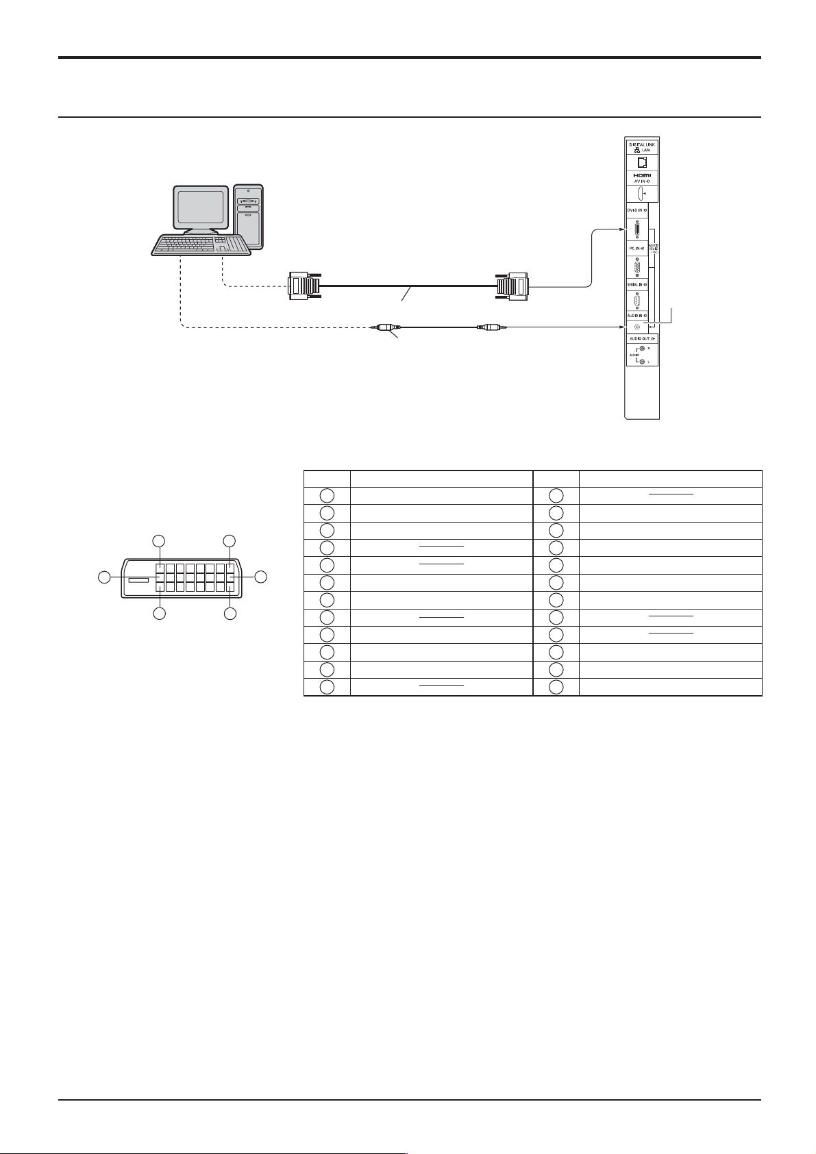
Connections
DVI-D IN connection
PC with DVI-D
video out
DVI-video cable (Within 5 m)
Stereo mini plug (M3)
Shared with
PC IN.
DVI-D Input Connector
Pin Layouts
24
16
8
Connection port view
17
9
1
Pin No.
Signal Name
T.M.D.S. data 2-
1
T.M.D.S. data 2+
2
T.M.D.S. data 2 shield
3
4
5
DDC clock
6
DDC data
7
8
T.M.D.S. data 1-
9
T.M.D.S. data 1+
10
T.M.D.S. data 1 shield
11
12 24
Note:
Additional equipment and cables shown are not supplied with this set.
Pin No.
13
14
15
16
17
18
19
20
21
22
23
Signal Name
+5 V DC
Ground
Hot plug detect
T.M.D.S. data 0T.M.D.S. data 0+
T.M.D.S. data 0 shield
T.M.D.S. clock shield
T.M.D.S. clock+
T.M.D.S. clock-
12
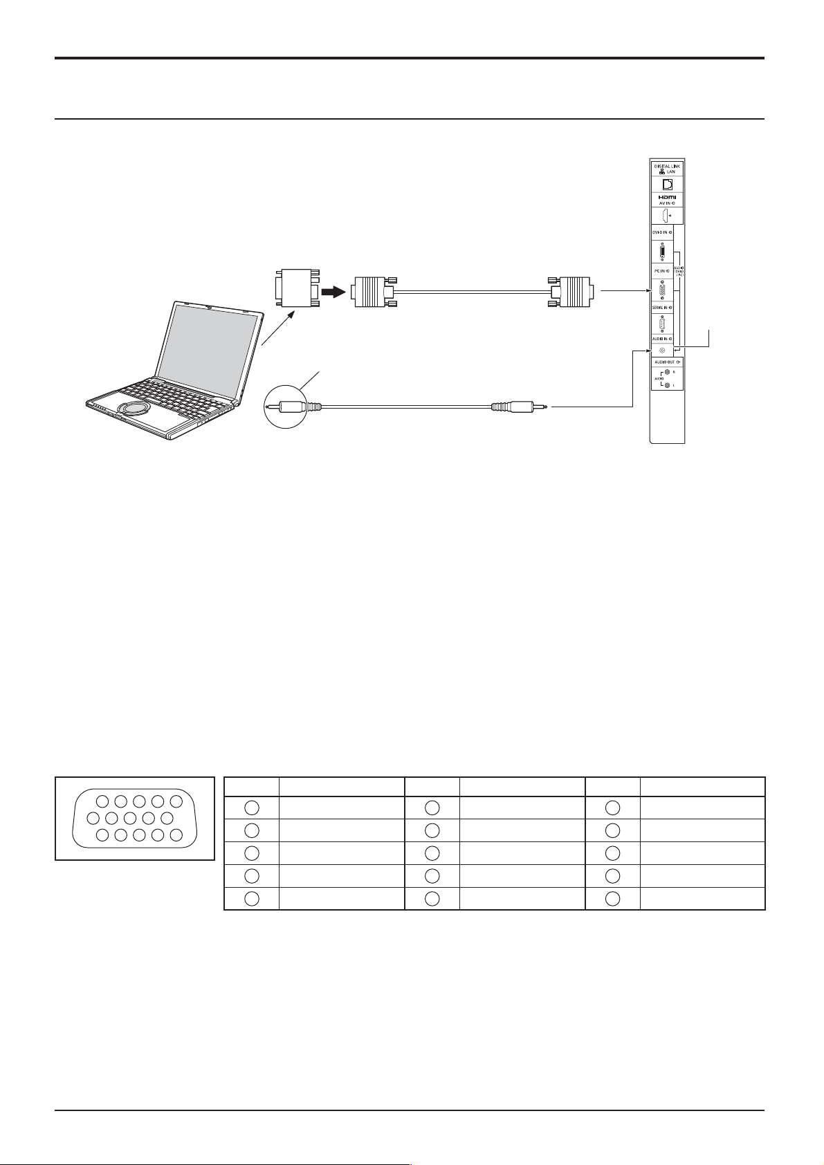
PC Input Terminals connection
Conversion adapter
(if necessary)
COMPUTER
Connect a cable which matches
the audio output terminal on the computer.
Audio
RGB
Mini D-sub 15p
(Male)
Stereo mini plug (M3)
Connections
(Female)
Shared with
DVI-D IN.
Notes:
• Computer signals which can be input are those with a horizontal scanning frequency of 30 to 110 kHz and vertical scanning
frequency of 48 to 120 Hz. (However, the image will not be displayed properly if the signals exceed 1,200 lines.)
• The display resolution is a maximum of 1,440 × 1,080 dots when the aspect mode is set to “4:3”, and 1,920 × 1,080
dots when the aspect mode is set to “16:9”. If the display resolution exceeds these maximums, it may not be possible
to show ne detail with suf cient clarity.
• The PC input terminals are DDC2B-compatible. If the computer being connected is not DDC2B-compatible, you will
need to make setting changes to the computer at the time of connection.
• Some PC models cannot be connected to the set.
• There is no need to use an adapter for computers with DOS/V compatible Mini D-sub 15P terminal.
• The computer shown in the illustration is for example purposes only.
• Additional equipment and cables shown are not supplied with this set.
• Do not set the horizontal and vertical scanning frequencies for PC signals which are above or below the speci ed
frequency range.
Signal Names for Mini D-sub 15P Connector
Pin No. Signal Name Pin No. Signal Name Pin No. Signal Name
1514131211
67839
1
2
10
45
Pin Layout for PC Input
Terminal
1
2
3
4
NC (not connected)
5
GND (Ground)
R
G
B
6
7
8
9
10
GND (Ground)
GND (Ground)
GND (Ground)
+5 V DC
GND (Ground)
11
NC (not connected)
12
13
14
15
HD/SYNC
SDA
VD
SCL
13
Connections
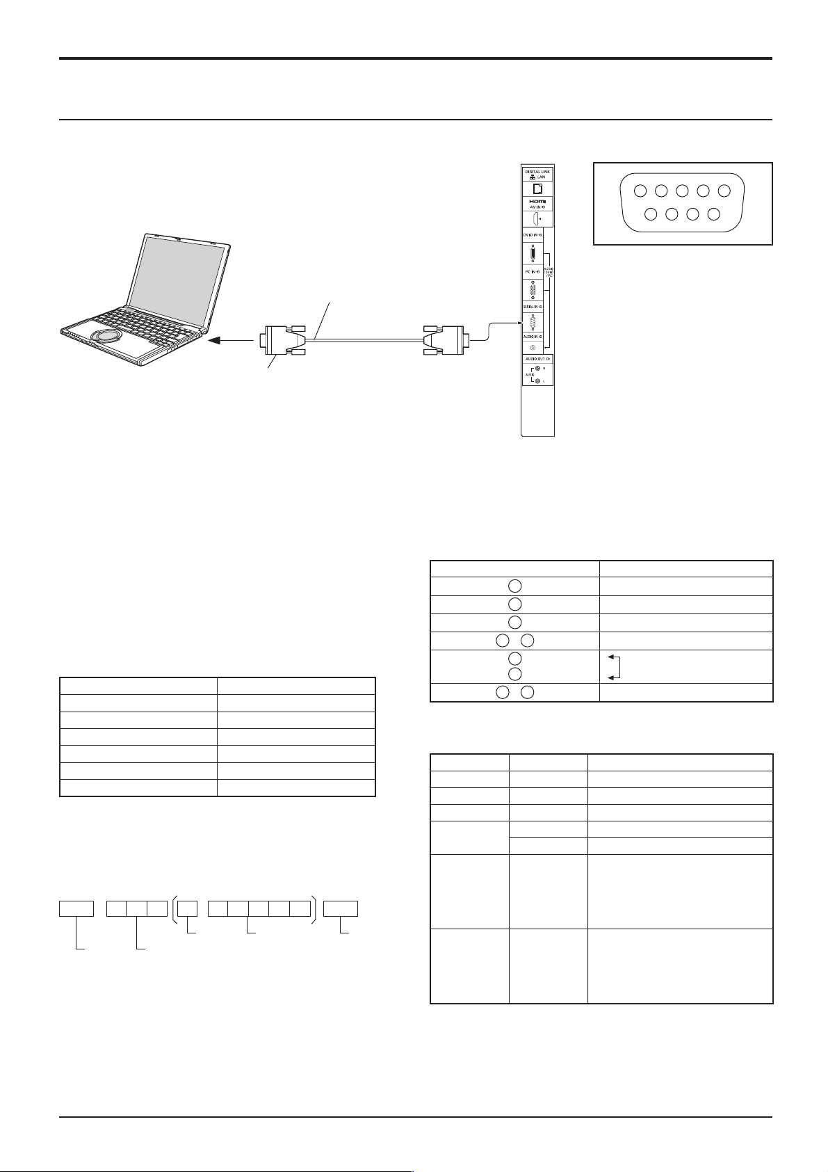
6 7 8 9
1 3 4 5 2
SERIAL Terminals connection
The SERIAL terminal is used when the Display is controlled by a computer.
COMPUTER
RS-232C Straight cable
(Female)
Pin layout for SERIAL Terminal
(Male)
Notes:
D-sub 9p
• Use the RS-232C straight cable to connect the computer to the Display.
• The computer shown is for example purposes only.
• Additional equipment and cables shown are not supplied with this set.
• When using serial control with this display, be sure to con gure the “Control I/F Select” in the “Network Setup” menu.
When controlling the Display with RS232C terminal, select “RS-232C (Serial)”. When controlling with the RS232C
terminal of a DIGITAL LINK device, select “RS-232C(DIGITAL LINK)”. (see page 43)
The SERIAL terminal conforms to the RS-232C interface
speci cation, so that the Display can be controlled by a
computer which is connected to this terminal.
The computer will require software which allows the
sending and receiving of control data which satis es
the conditions given below. Use a computer application
such as programming language software. Refer to the
documentation for the computer application for details.
Communication parameters
Signal level RS-232C compliant
Synchronization method Asynchronous
Baud rate 9600 bps
Parity None
Character length 8 bits
Stop bit 1 bit
Flow control None
Basic format for control data
The transmission of control data from the computer starts with
a STX signal, followed by the command, the parameters, and
lastly an ETX signal in that order. If there are no parameters,
then the parameter signal does not need to be sent.
STX C1 C2 C3 P1 P2 P3 P4: P5 ETX
Start
(02h)
Colon Parameter(s)
3-character
command (3 bytes)
(1 - 5 bytes)
End
(03h)
Notes:
• If multiple commands are transmitted, be sure to wait for
the response for the rst command to come from this unit
before sending the next command.
Signal names for D-sub 9P connector
Pin No. Details
2
3
5
4
6
•
7
8
1
9
•
R X D
T X D
GND
Non use
(Shorted in this set)
NC
These signal names are those of computer speci cations.
Command
Command Parameter Control details
PON None Power ON
POF None Power OFF
AVL *** Volume 000 - 100
AMT
IMS None
DAM None
0 Audio MUTE OFF
1 Audio MUTE ON
HM1
DV1
PC1
DL1
ZOOM
FULL
NORM
ZOM2
Input select (toggle)
HDMI input (HDMI)
DVI-D IN input (DVI)
PC IN input (PC)
DIGITAL LINK input
Screen mode select (toggle)
Zoom1
16:9
4:3
Zoom2
With the power off, this display responds to PON
command only.
• If an incorrect command is sent by mistake, this unit will
send an “ER401” command back to the computer.
• Consult an Authorized Service Center for detail instructions
on command usage.
14
 Loading...