

Page 1
Operating Instructions
FULL HD LCD Display
Model No.
TH-47LFV5U
English
Before connecting, operating or adjusting this product,
please read these instructions completely.
Please keep this manual for future reference.
Page 2
CAUTION
RISK OF ELECTRIC SHOCK
DO NOT OPEN
WARNING: To reduce the risk of electric shock, do not remove cover or back.
No user-serviceable parts inside. Refer servicing to qualied service personnel.
The lightning ash with arrowhead within a triangle is intended
to tell the user that parts inside
the product are a risk of electric
shock to persons.
WARNING : To prevent damage which may result in re or shock hazard, do not expose this apparatus to rain or moisture.
Do not place containers with water (ower vase, cups, cosmetics, etc.) above the set.
(including on shelves above, etc.)
WARNING : 1) To prevent electric shock, do not remove cover. No user serviceable parts inside. Refer servicing to
qualied service personnel.
2) Do not remove the grounding pin on the power plug. This apparatus is equipped with a three pin groundingtype power plug. This plug will only t a grounding-type power outlet. This is a safety fea ture.
If you are unable to insert the plug into the outlet, contact an electrician.
Do not defeat the purpose of the grounding plug.
The exclamation point within a
triangle is intended to tell the
user that important operating
and servicing instructions are in
the papers with the appliance.
2
Page 3
Important Safety Instructions
1) Read these instructions.
2) Keep these instructions.
3) Heed all warnings.
4) Follow all instructions.
5) Do not use this apparatus near water.
6) Clean only with dry cloth.
7) Do not block any ventilation openings. Install in accordance with the manufacturer’s instructions.
8) Do not install near any heat sources such as radiators, heat registers, stoves, or other apparatus (including ampliiers) that
produce heat.
9) Do not defeat the safety purpose of the polarized or grounding-type plug. A polarized plug has two blades with one wider
than the other. A grounding type plug has two blades and a third grounding prong. The wide blade or the third prong are
provided for your safety. If the provided plug does not t into your outlet, consult an electrician for replacement of the
obsolete outlet.
10) Protect the power cord from being walked on or pinched particularly at plugs, convenience receptacles, and the point where
they exit from the apparatus.
11) Only use attachments / accessories specied by the manufacturer.
12) Use only with the cart, stand, tripod, bracket, or table specied by the manufacturer, or sold with the
apparatus. When a cart is used, use caution when moving the cart / apparatus combination to avoid injury
from tip-over.
13) Unplug this apparatus during lightning storms or when unused for long periods of time.
14) Refer all servicing to qualied service personnel. Servicing is required when the apparatus has been
damaged in any way, such as power-supply cord or plug is damaged, liquid has been spilled or objects have fallen into the
apparatus, the apparatus has been exposed to rain or moisture, does not operate normally, or has been dropped.
15) To prevent electric shock, ensure the grounding pin on the AC cord power plug is securely connected.
3
Page 4
Dear Panasonic Customer
Welcome to the Panasonic family of customers. We hope that you will have many years of enjoyment from
your new LCD Display.
To obtain maximum benet from your set, please read these Instructions before making any adjustments,
and retain them for future reference.
Retain your purchase receipt as well, and record the model number and serial number of your set in the
space provided on the rear cover of these instructions.
Visit our Panasonic Web Site http://panasonic.net
Table of Contents
Important Safety Instructions .................................. 3
FCC STATEMENT ...................................................... 5
Safety Precautions ................................................... 6
Maintenance .............................................................. 7
Accessories .............................................................. 8
Accessories Supplied ......................................... 8
VESA Mounting .................................................. 9
Cautions when installing or moving .................... 9
Parts and Functions ............................................... 10
Control Panel .................................................... 10
Input/Output Terminals ......................................11
Connections ............................................................ 12
AC Cord Connection ........................................ 12
Cable Securing ................................................. 12
DVD/VCR/VCD Connection ............................. 13
PC Connection ................................................. 15
External Audio Connection ............................... 17
SERIAL Terminals Connection ......................... 18
Daisy-chain Connection ................................... 19
Using Network Function ........................................ 20
Network Connection ......................................... 20
OSD Menu Setup for Network Connection ....... 21
Using Web Browser Control .................................. 22
Before Using Web Browser Control ................. 22
Access from Web Browser ............................... 23
On-Screen Display Menu ....................................... 24
Entering the OSD Menu ................................... 24
OSD Menu Overview ........................................ 24
PICTURE menu ........................................... 24
TILING .......................................................... 28
POWER SAVE ............................................. 28
SCREEN SAVER ......................................... 29
Input Mode .............................................................. 31
Cleaning and Troubleshooting .............................. 32
Cleaning ........................................................... 32
Troubleshooting ................................................ 33
Technical Specications ........................................ 35
4
Page 5
1
FCC STATEMENT
This equipment has been tested and found to comply with the limits for a Class A digital device, pursuant to Part 15 of the
FCC Rules. These limits are designed to provide reasonable protection against harmful interference when the equipment is
operated in a commercial environment. This equipment generates, uses and can radiate radio frequency energy and, if not
installed and used in accordance with the instructions manual, may cause harmful interference to radio communications.
Operation of this equipment in a residential area is likely to cause harmful interference in which case the user will be required
to correct the interference at his own expense.
FCC CAUTION:
To assure continued compliance, follow the attached installation instructions and use only the provided power
supply cord with ferrite core and DVI interface cable with two ferrite cores.
cable must contain two ferrite cores. Any changes or modications not expressly approved by Panasonic Corp. of
North America could void the user's authority to operate this device.
Declaration of Verication
Model No. TH-47LFV5U
Responsible Party: Panasonic Corporation of North America
Two Riverfront Plaza, Newark, NJ 07102-5490
Contact Source: Panasonic System Communications Company of
North America 1-800-973-4390
2
The user provided VGA video signal
This device complies with Part 15 of the FCC Rules and all applicable IC RSS standards. Operation is subject to the
following two conditions: (1) This device may not cause harmful interference, and (2) this device must accept any interference
received, including interference that may cause undesired operation.
1
The following type information may appears elsewhere in the O/I: Panasonic does not guarantee operation and performance of peripheral
devices made by other manufacturers; and we disclaim any liability or damage arising from operation and/or performance from usage of
such other maker’s peripheral devices.
2
The O/I hook-up instructions must indicate the provided DVI interface cable contains two ferrite cores; and the user provided VGA video
signal cable must contain two ferrite cores.
CANADIAN NOTICE:
This Class A digital apparatus complies with Canadian ICES-003.
NOTE:
Image retention may occur. If you display a still picture for an extended period, the image might remain on the screen.
However, it will disappear after a while.
Trademark Credits
• VGA is a trademark of International Business Machines Corporation.
• Macintosh is a registered trademark of Apple Inc., USA.
• SVGA, XGA, SXGA and UXGA are registered trademarks of the Video Electronics Standard Association.
• Even if no special notation has been made of company or product trademarks, these trademarks have been fully
respected.
• HDMI, the HDMI Logo, and High-Denition Multimedia Interface are trademarks or registered trademarks of HDMI
Licensing LLC in the United States and other countries.
5
Page 6
Safety Precautions
CAUTION
This LCD Display is for use only with the following optional accessories. Use with any other type of optional
accessories may cause instability which could result in the possibility of injury.
(All of the following accessories are manufactured by Panasonic Corporation.)
• Remote Control Kit ................................... TY-RM50VW
• Cover-frame Kit ....................................... TY-CF47VW5
Always be sure to ask a qualied technician to carry out set-up.
Small parts can present choking hazard if accidentally swallowed. Keep small parts away from young children. Discard
unneeded small parts and other objects, including packaging materials and plastic bags/sheets to prevent them from being
played with by young children, creating the potential risk of suffocation.
When using the LCD Display
Do not bring your hands, face or objects close to the
ventilation holes of this Display.
• Top of this Display is usually very hot due to the high
temperature of exhaust air being released through the
ventilation holes. Burns or personal injuries can happen
if any body parts are brought too close. Placing any
object near the top of this Display could also result in
heat damages to the object as well as to this Display if its
ventilation holes are blocked.
Be sure to disconnect all cables before moving this
Display.
• Moving this Display with its cables attached might
damage the cables which, in turn, can cause re or
electric shock.
Disconnect the power plug from the wall outlet as a
safety precaution before carrying out any cleaning.
• Electric shocks can result if this is not done.
Clean the power cable regularly to prevent it from
becoming dusty.
• Built-up dust on the power cord plug can increase
humidity which might damage the insulation and cause
re. Unplug the cord from the wall outlet and clean it with
a dry cloth.
NOTE:
• Image retention may occur. If you display a still picture
for an extended period, the image might remain on the
screen. However, it will disappear after a while.
6
Page 7
WARNING
Safety Precautions
Setup
Do not place this Display on sloped or unstable surfaces,
and ensure that this Display does not hang over the edge
of the base.
• The Display may fall off or tip over.
Do not place any objects on top of this Display.
• If water spills onto this Display or foreign objects get
inside it, a short-circuit may occur which could result in
re or electric shock. If any foreign objects get inside this
Display, please consult an Authorized Service Center.
Do not cover the ventilation holes.
• Doing so may cause this Display to overheat, which can
cause re or damage to this Display.
Transport only in upright position!
• Transporting the unit with its display panel facing upright
or downward may cause damage to the internal circuitry.
For sufcient ventilation;
• Leave a space of 3-15/16” (10 cm) or more at the top,
bottom, left, and right to the outermost circumference of
this Display.
• Leave a space of 1-31/32” (5cm) or more at the rear.
Cautions for Wall Installation
• Wall installation should be performed by an installation
professional. Installing this Display incorrectly may lead
to an accident that results in death or serious injury.
Furthermore, when installing on a wall, a UL standard
certied wall hanging bracket (VESA 400 × 400) must be
used.
NOTE: Reffer to page 9 “VESA Mounting”.
An apparatus with CLASS I construction shall be
connected to a mains socket outlet with a protective
earthing connection.
AC Power Supply Cord
The Display is designed to operate on 110 - 127 V AC,
50/60 Hz.
Ensure that the mains plug is easily accessible.
Do not use any power supply cord other than that
provided with this unit.
• Doing so may cause re or electric shocks.
Securely insert the power cord plug as far as it will go.
• If the plug is not fully inserted, heat may be generated
which could cause re. If the plug is damaged or the wall
socket plate is loose, they should not be used.
Do not handle the power cord plug with wet hands.
• Doing so may cause electric shocks.
Do not do anything that might damage the power cable.
When disconnecting the power cable, hold the plug, not
the cable.
• Do not make any modications, place heavy objects on,
place near hot objects, heat, bend, twist or forcefully pull
the power cable. Doing so may cause damage to the
power cable which can cause re or electric shock. If
damage to the cable is suspected, have it repaired at an
Authorized Service Center.
If this Display will not be used for a long period of time,
unplug the power cord from the wall outlet.
If problems occur during use
If a problem occurs (such as no picture or no sound), or if
smoke or an abnormal odor is detected from this Display,
unplug the power cord immediately.
• Continuous use of this Display under these conditions
might cause re or permanent damage to the unit. Have
this Display evaluated at an Authorized Service Center.
Services to this Display by any unauthorized personnel
are strongly discouraged due to its high voltage
dangerous nature.
If water or foreign objects get inside this Display, if this
Display is dropped, or if the cabinet becomes damaged,
disconnect the power cord plug immediately.
• A short may occur, which could cause re. Contact an
Authorized Service Center for any repairs that need to be
made.
Maintenance
The front of this Display panel has been specially treated. Wipe the panel surface gently using only a cleaning cloth or
a soft, lint-free cloth.
• If the surface is particularly dirty, wipe with a soft, lint-free cloth which has been soaked in pure water or water in which
neutral detergent has been diluted 100 times, and then wipe it evenly with a dry cloth of the same type until the surface is
dry.
• Do not scratch or hit the surface of the panel with ngernails or other hard objects, otherwise the surface may become
damaged. Furthermore, avoid contact with volatile substances such as insect sprays, solvents and thinner, otherwise the
quality of the surface may be adversely affected.
If the cabinet becomes dirty, wipe it with a soft, dry cloth.
• If the cabinet is particularly dirty, soak the cloth in water to which a small amount of neutral detergent has been added and
then wring the cloth dry. Use this cloth to wipe the cabinet, and then wipe it dry with a dry cloth.
• Do not allow any detergent to come into direct contact with the surface of this Display. If water droplets get inside the unit,
operating problems may result.
• Avoid contact with volatile substances such as insect sprays, solvents and thinner, otherwise the quality of the cabinet
surface may be adversely affected or the coating may peel off. Furthermore, do not leave it for long periods in contact with
articles made from rubber or PVC.
Usage of a chemical cloth
• Do not use a chemical cloth for the panel surface.
• Follow the instructions for the chemical cloth to use it for the cabinet.
7
Page 8
Accessories
Accessories Supplied
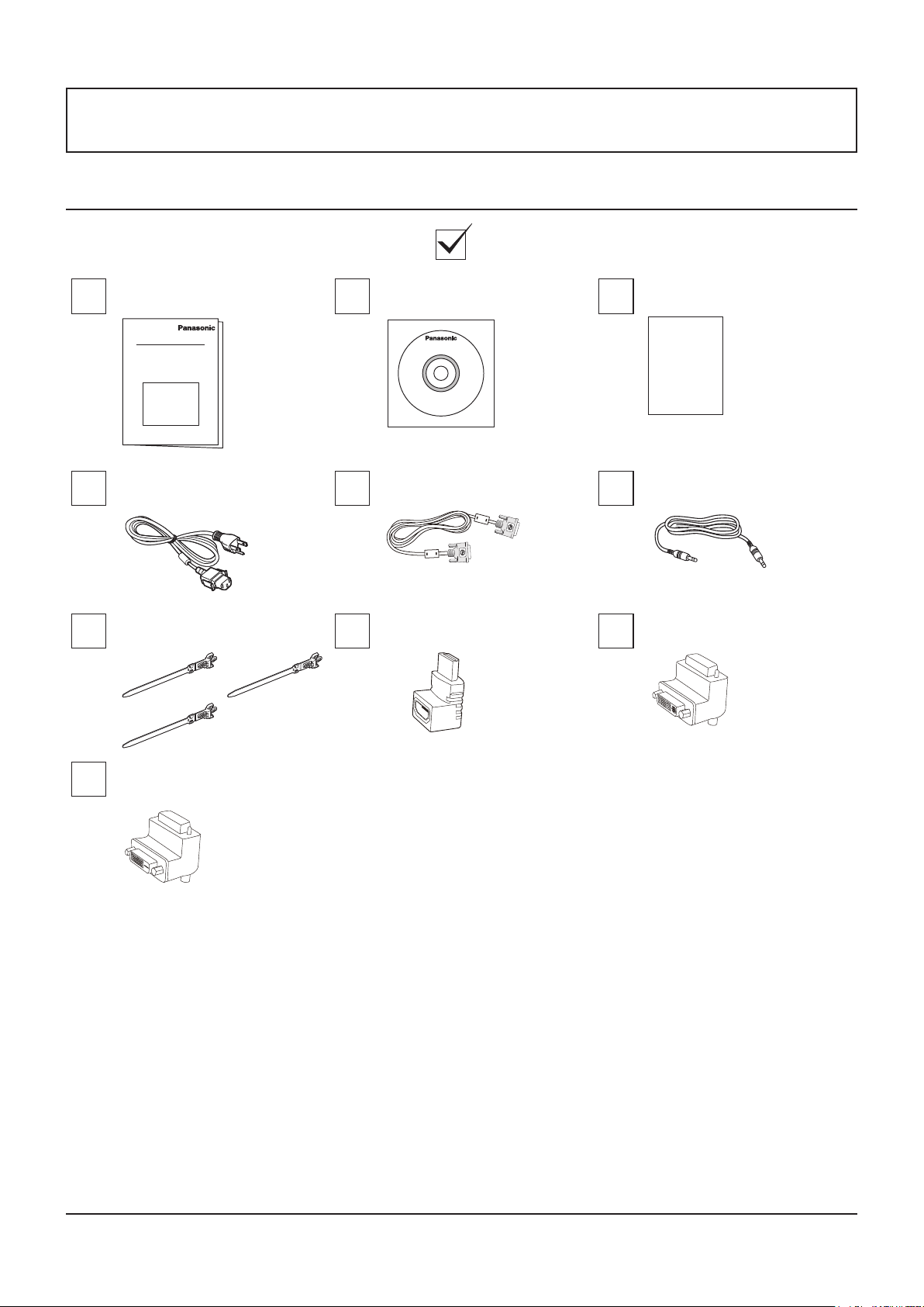
Check that you have the Accessories and items shown
Operation instruction book CD-ROM (Operation instruction) Warranty card (For Mexico only)
Warranty
AC Power Cord DVI cable
Wire clampers L type connector of HDMI L type connector of "DVI-I".
L type connector of "DVI-D".
NOTE:
• The remote control is not supplied.
• In the case of wiring of DVI and HDMI, when there is no margin in downward space, please use the L type connector.
Connector cable of remote
control
8
Page 9
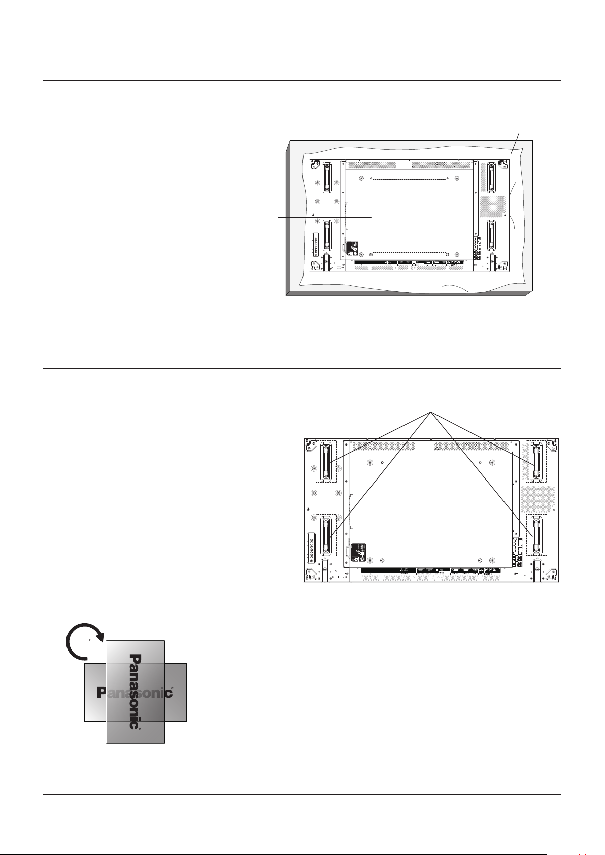
VESA Mounting
To mount this Display to a wall, you will have to obtain a standard wall-mounting kit (commercially available). We recommend
using a mounting interface that complies with TUV-GS and/or UL1678 standard in North America.
1. Lay a protective sheet on a table, which
was wrapped around this Display when it
was packaged, beneath the screen surface
so as not to scratch the screen face.
2. Ensure you have all accessories for
mounting this Display (wall mount, ceiling
mount, etc).
3. Follow the instructions that came with
the wall mounting kit. Failing to follow the
correct mounting procedures could result
in damage to the equipment, or injury to
the user or install personnel. The product
warranty does not cover the damage
caused by improper installation.
4. For the wall-mounting kit, use M6 mounting
screws (having a length 10 mm longer than
the thickness of the mounting bracket) and
tighten them securely.
VESA Grid
Table
Cautions when installing or moving
To prevent this Display from falling:
• Grab the handles when moving this Display.
• Do not touch any parts excep the handles.
• Handle with care and with more than two persons
when moving this Display. Keep in mind that this
Display is easy to break from carelessness.
• For wall or ceiling installation, we recommend
installing this Display with metal brackets
which are commercially available. For detailed
installation instructions, refer to the guide received
with the respective bracket.
• To lessen the probability of injury and damage
resulting from fall of this Display in case of
earthquake or other natural disaster, be sure to
consult the bracket manufacturer for installation
location.
• For portrait installation, please turn this Display
right.
When you install a display by multi, please prepare for 0.5 mm between
each display in the state of the power supply OFF.
Protective Sheet
EXT SP(8Ω,20W[10W+10W])
Handle
EXT SP(8Ω,20W[10W+10W])
90
NOTE:
• Please do not rotate and use it for left-hand side.
9
Page 10
Parts and Functions
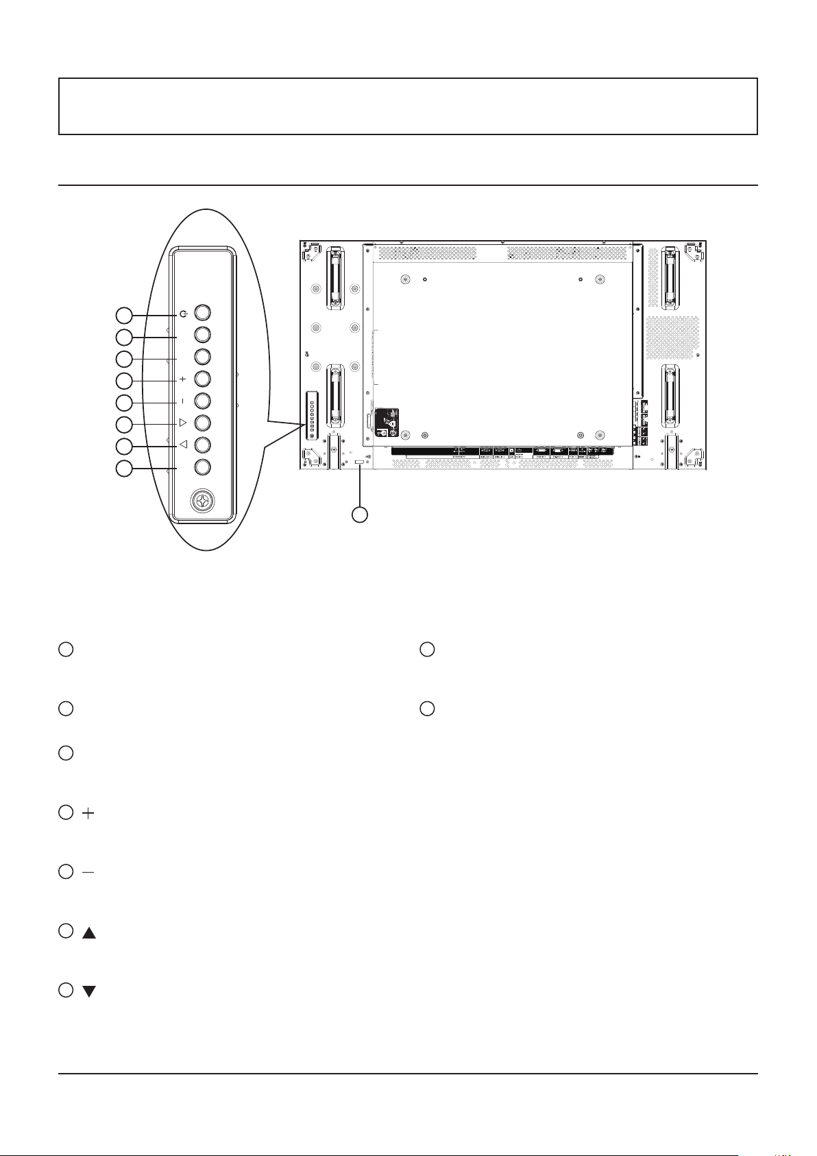
Control Panel
1 2 3 4 5 6 7 8
1
POWER button
Use this button to turn this Display on or put this Display
to standby.
MUTE INPUT MENU
EXT SP(8Ω,20W[10W+10W])
9
8
MENU button
Press to activate the OSD menu when OSD menu is off.
Press to return to previous menu while OSD menu is on.
2
MUTE button
Switch the audio mute ON/OFF.
3
INPUT button
Use this button to select the input source.
• Used as [SET] button in the On-Screen-Display menu.
4
[ ] button
Increase the adjustment while OSD menu is on, or
increase the audio output level while OSD menu is off.
5
[ ] button
Decrease the adjustment while OSD menu is on, or
decrease the audio output level while OSD menu is off.
6
[ ] button
Move the highlight bar up to adjust the selected item while
OSD menu is on.
7
[ ] button
Move the highlight bar down to adjust the selected item
while OSD menu is on.
10
9
Remote control sensor and power status
indicator
• Receives command signals from the remote control.
• Indicates the operating status of this Display:
- Lights green when this Display is turned on
- Lights red when this Display is in standby mode
- Lights red and green when this Display enters “Power
Save” mode
- When {SCHEDULE} is enabled, the indicator lights
blinking green and static red
- If the light blinks red, it indicates that a failure has
been detected
- Off when the main power of this Display is turned off
Page 11
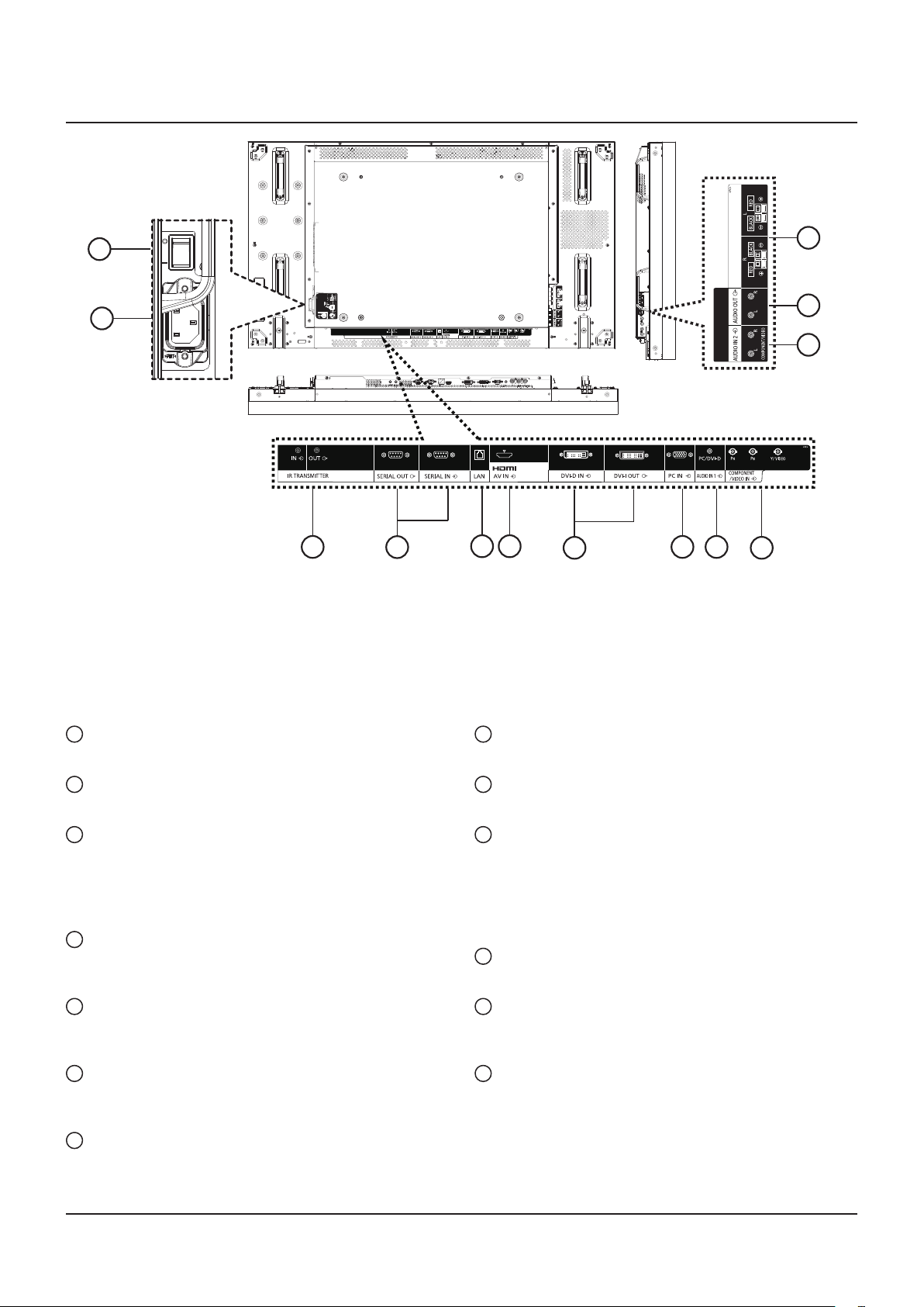
Input/Output Terminals
2
EXT SP(8Ω,20W[10W+10W])
1
EXT SP(8Ω,20W[10W+10W])
13
12
11
3
4
5 6
7
8 9
10
1
AC IN
Connect the supplied power cord to the wall outlet.
2
MAIN POWER SWITCH
Press to switch the main power on/off.
3
IR TRANSMITTER IN / OUT
Reserved for the wired connection of the IR control.
NOTE: If an optional IR receiver is connected to [IR
TRANSMITTER IN], this Display’s remote control
sensor will stop working.
4
SERIAL OUT / SERIAL IN
RS232C network input/output connection for the use of
loop-through function.
5
LAN
LAN control function for the use of remote control signal
from control center.
6
HDMI AV IN
Input the HDMI source of an AV device, or the DVI-D
output of a PC by using a DVI-HDMI cable.
7
DVI-D IN / DVI-I OUT
Digital video input and output connection.
8
PC IN
Input the PC source.
9
AUDIO IN 1
Input the PC audio source (3.5 mm stereo phone jack).
10
COMPONENT/VIDEO IN (BNC)
Input the component YPbPr source from external AV
device.
For VIDEO input, connect with CVBS cable from the video
output of your AV device to this Display’s Y input (an aftermarket BNC-RCA adapter will be needed).
11
AUDIO IN 2 (RCA)
Input the audio source from external AV device.
12
AUDIO OUT (RCA)
Output the audio source connected from the AUDIO IN
jack to an external AV device.
13
SPEAKER OUT R/L -> EXT SP (8 Ω)
Output the audio to your external speakers.
11
Page 12
Connections
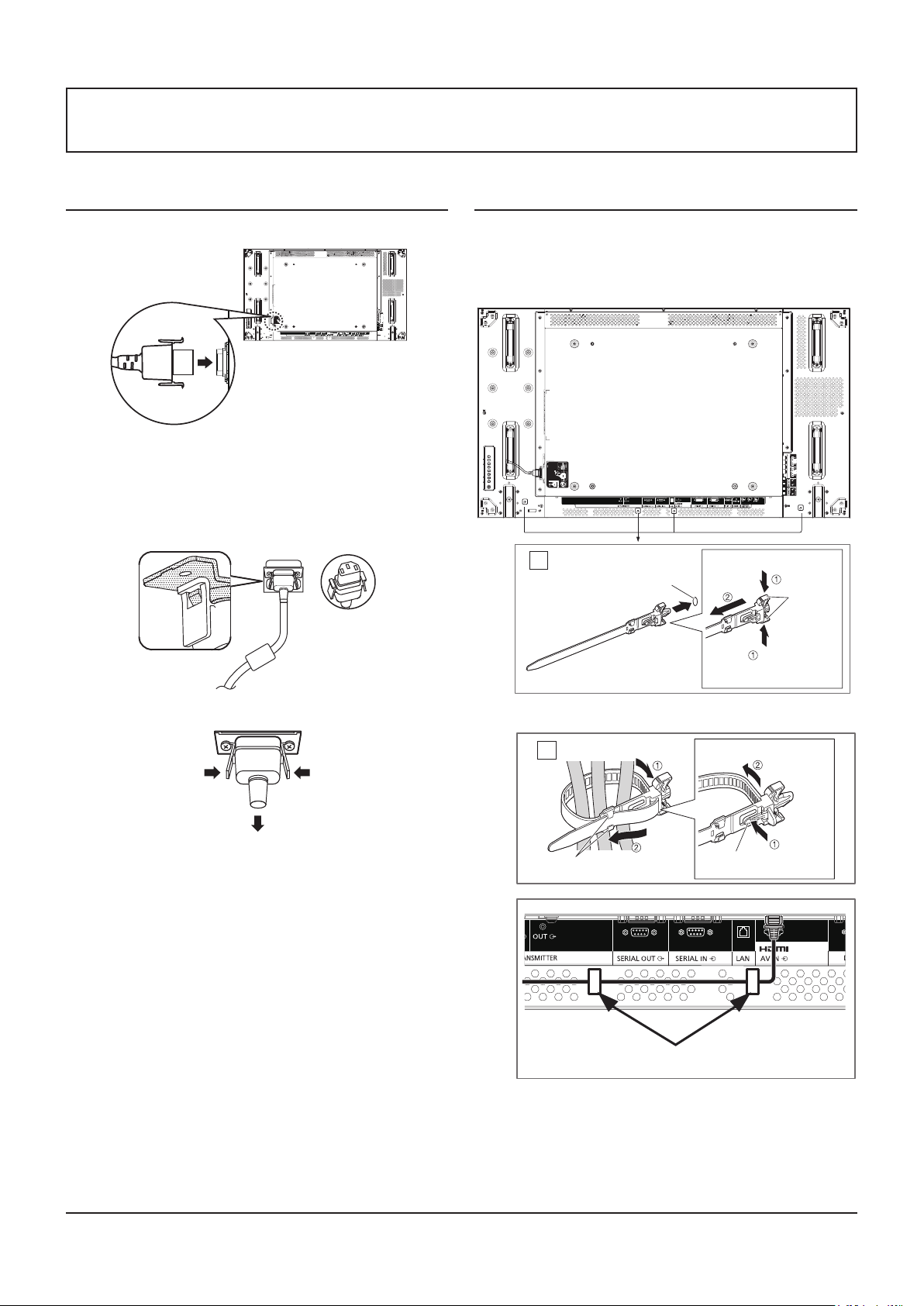
AC Cord Connection
1. Plug the AC cord into this Display.
EXT SP(8Ω,20W[10W+10W])
2. Plug the AC cord rmly until it clicks into position. Make
sure he AC cord is locked on both the left and right sides.
Cable Securing
There are three clampers supplied to secure cables at three
positions.
1. Attach the clamper.
EXT SP(8Ω,20W[10W+10W])
Attach the clamper
1
hole
To remove from the unit:
snaps
3. To unplug the AC cord, press the two knobs and pull.
NOTE:
• When disconnecting the AC cord, be absolutely sure to
disconnect the AC cord plug at the socket outlet rst.
2. Bundle the cables.
Bundle the cables
2
hooks
In order to prevent slack of a HDMI connector,
please fix certainly by a clamper.
Insert the clamper
in a hole.
Set the
tip in the
hooks
To loosen:
knob
Keep
pushing both
side snaps
Keep
pushing
the knob
12
Page 13
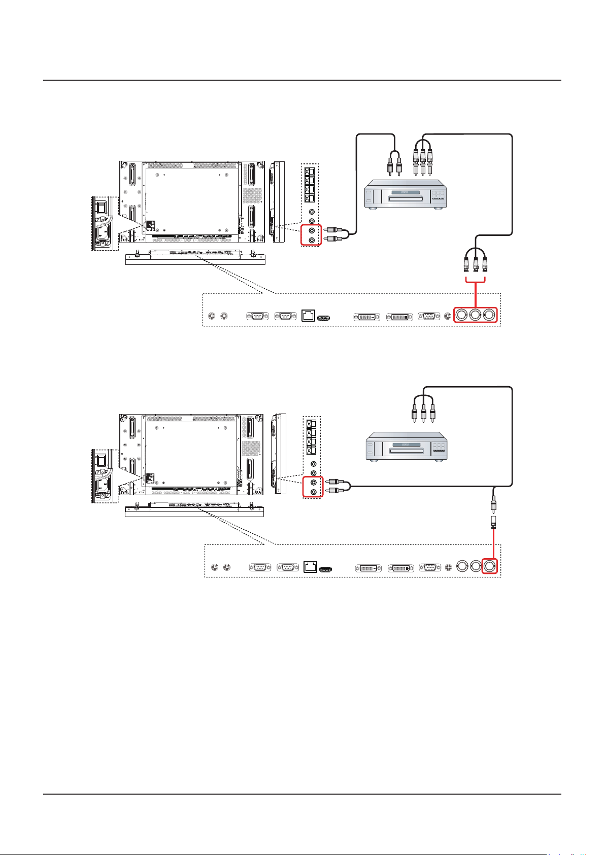
DVD/VCR/VCD Connection
Using COMPONENT input
Audio Out
COMPONENT Out
(YPbPr)
Using VIDEO input
EXT SP(8Ω,20W[10W+10W])
EXT SP(8Ω,20W[10W+10W])
[R]
[L]
[R]
[L]
DVD / VCR / VCD
[AUDIO IN 2]
DVD / VCR / VCD
[AUDIO IN 2]
[COMPONENT IN]
[White]
AV Out
(YPbPr)
[Yellow][Red]
[Yellow]
13
Page 14
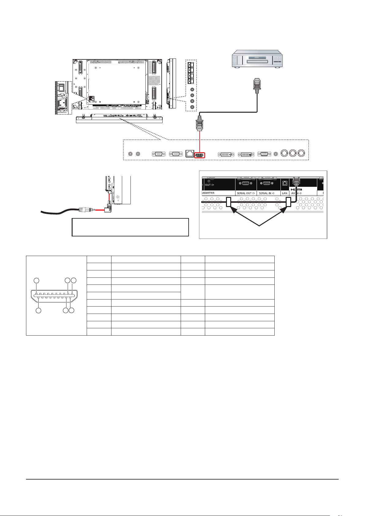
Using HDMI video input
DVD / VCR / VCD
HDMI Out
EXT SP(8Ω,20W[10W+10W])
[HDMI IN]
When there is no margin in downward space,
please use the L type connector.
Pin assignments and signal names for HDMI terminal:
Pin No. Signal Name Pin No. Signal Name
1 T.M.D.S. Data2 + 11 T.M.D.S. Clock Shield
2 T.M.D.S. Data2 Shield 12 T.M.D.S. Clock -
1
19
18
3
3 T.M.D.S. Data2 - 13 CEC
4 T.M.D.S. Data1 +
5 T.M.D.S. Data1 Shield
6 T.M.D.S. Data1 - 15 SCL
2
4
7 T.M.D.S. Data0 + 16 SDA
8 T.M.D.S. Data0 Shield 17 DDC/CEC Ground
9 T.M.D.S. Data0 - 18 +5 V DC
10 T.M.D.S. Clock + 19 Hot Plug Detect
In order to prevent slack of a HDMI connector,
please fix certainly by a clamper.
14
Reserved(N.C. on device)
14
Page 15
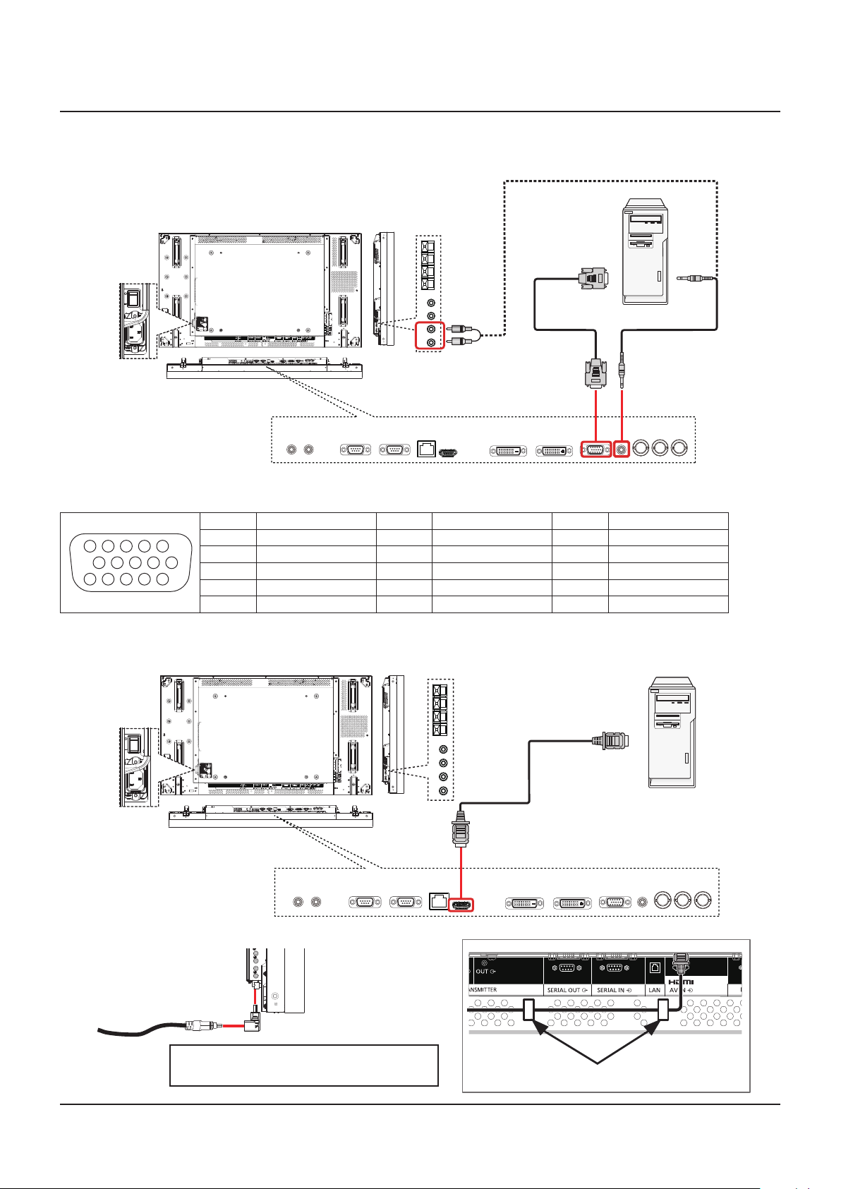
PC Connection
Using PC input
PC Out
D-Sub 15 pin
EXT SP(8Ω,20W[10W+10W])
Signal names for mini D-sub 15-pin connector:
Pin No. Signal Name Pin No. Signal Name Pin No. Signal Name
4 5
2
10
15 14 13 12 11
1
6 7 8 3 9
1 R 6 GND (Ground) 11 NC (not connected)
2 G 7 GND (Ground) 12 SDA
3 B 8 GND (Ground) 13 HD/SYNC
4 NC (not connected) 9 +5 V DC 14 VD
5 GND (Ground) 10 GND (Ground) 15 SCL
Using HDMI input
[R]
[L]
[AUDIO IN 2]
PC
Audio Out
[PC IN] [AUDIO IN 1]
EXT SP(8Ω,20W[10W+10W])
When there is no margin in downward space,
please use the L type connector.
HDMI Out
PC
[HDMI IN]
In order to prevent slack of a HDMI connector,
please fix certainly by a clamper.
15
Page 16
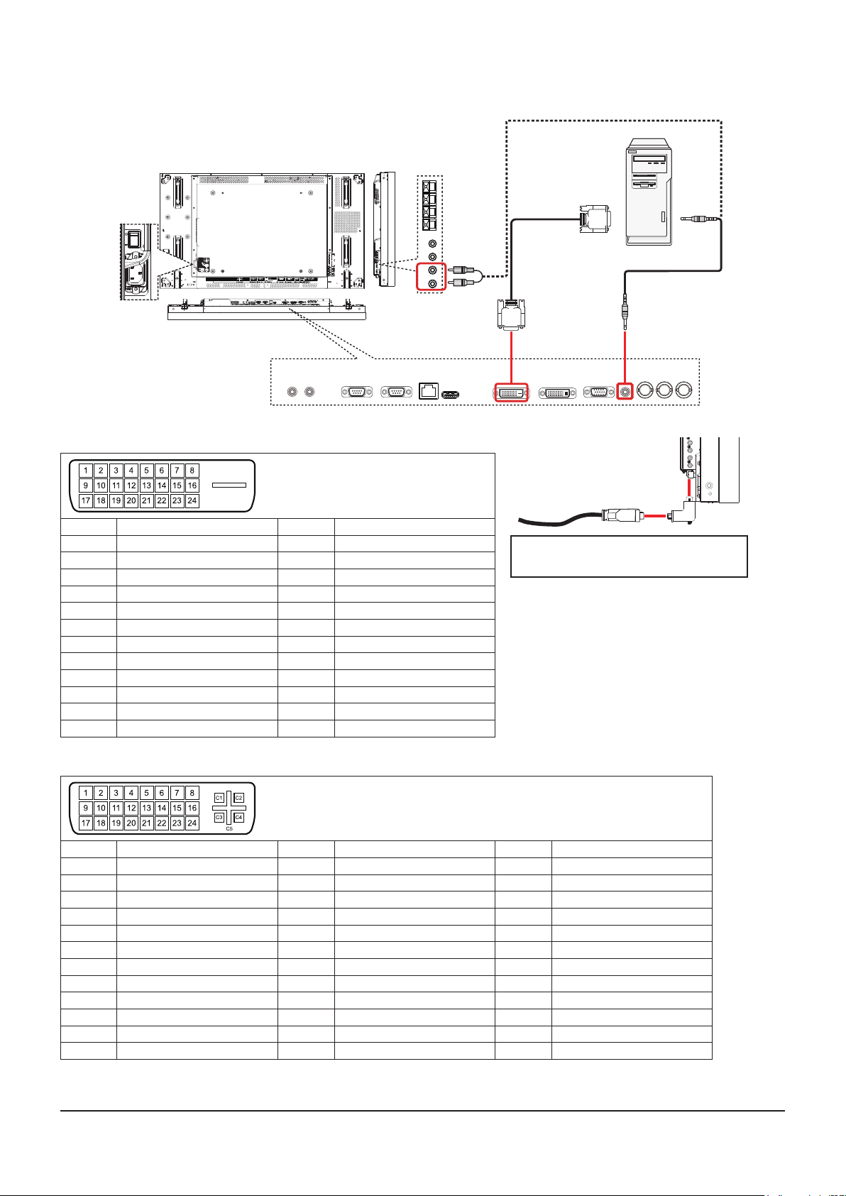
Using DVI input
EXT SP(8Ω,20W[10W+10W])
DVI-D Input Connector Pin Layouts:
Pin No. Signal Name Pin No. Signal Name
1 T.M.D.S. Data2 - 13 —
2 T.M.D.S. Data2 + 14 +5 V DC
3 T.M.D.S. Data2 Shield 15 Ground
4 —
5 — 17 T.M.D.S. Data0 -
6 DDC Clock 18 T.M.D.S. Data0 +
7 DDC Data 19 T.M.D.S. Data0 Shield
8 — 20 —
9 T.M.D.S. Data1 - 21 —
10 T.M.D.S. Data1 + 22 T.M.D.S. Clock Shield
11 T.M.D.S. Data1 Shield 23 T.M.D.S. Clock +
12 — 24 T.M.D.S. Clock -
16
Hot Plug Detect
[R]
[L]
[AUDIO IN 2]
PC
Audio Out
[DVI-D IN]
[AUDIO IN 1]
When there is no margin in downward
space, please use the L type connector.
In order to connect certainly also including the
case where an L type connector is used, please
tighten the screw of both ends certainly. When
the screw is not certainly being xed, connection of a daisy chain may become unstable.
DVI-I Output Connector Pin Layouts:
Pin No. Signal Name Pin No. Signal Name Pin No. Signal Name
1 T.M.D.S. Data2 - 13 — C1 Analog Red
2 T.M.D.S. Data2 + 14 +5 V DC C2 Analog Green
3 T.M.D.S. Data2 Shield 15 Ground C3 Analog Blue
4 — 16 Hot Plug Detect C4 Analog Horizontal Sync
5 — 17 T.M.D.S. Data0 - C5 Analog Ground
6 DDC Clock 18 T.M.D.S. Data0 +
7 DDC Data 19 T.M.D.S. Data0 Shield
8 Analog Vertical Sync 20 —
9 T.M.D.S. Data1 - 21 —
10 T.M.D.S. Data1 + 22 T.M.D.S. Clock Shield
11 T.M.D.S. Data1 Shield 23 T.M.D.S. Clock +
12 — 24 T.M.D.S. Clock -
16
Page 17
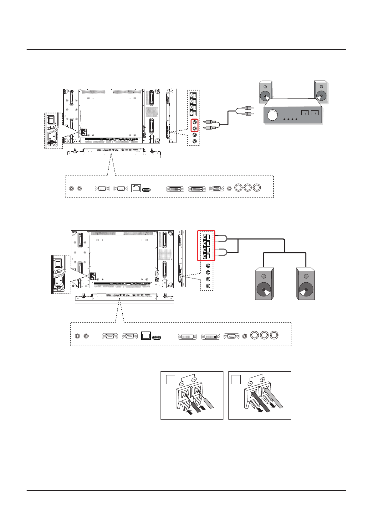
External Audio Connection
Using audio out
Audio In
[R]
Using speakers out
EXT SP(8Ω,20W[10W+10W])
EXT SP(8Ω,20W[10W+10W])
[L]
[AUDIO OUT]
Stereo Amplifier
External speakers
To connect the speaker wire:
1. While pressing the lever, insert the core wire.
2. Return the lever.
1
Black
Red
2
Red
Black
17
Page 18
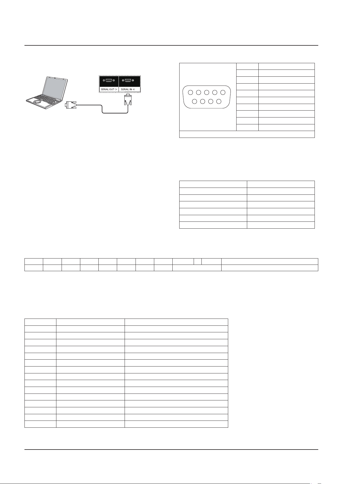
SERIAL Terminals Connection
The SERIAL terminal is used when this Display is controlled by
a computer.
Display No.1
[RS-232C]
NOTES:
• Use the RS-232C cross cable to connect the computer to
this Display.
• The computer shown is for example purposes only.
• Additional equipment and cables shown are not supplied
with this set.
The SERIAL terminal conforms to the RS-232C interface
specication, so that this Display can be controlled by a
computer which is connected to this terminal.
The computer will require software which allows the sending
and receiving of control data which satises the conditions
given below. Use a computer application such as programming
language software. Refer to the documentation for the computer
application for details.
Signal names for SERIAL IN terminal:
Pin No. Signal Name
1 DCD
2 RXD
1 3 4 5 2
6 7 8 9
These signal names are those of computer specications.
3 TXD
4 DTR
5 GND
6 DSR
7 RTS
8 CTS
9 RI
Communication parameters:
Signal level RS-232C compliant
Synchronization method Asynchronous
Baud rate 9600 bps
Parity None
Character length 8 bits
Stop bit 1 bit
Flow control
-
Basic format for control data:
The transmission of control data from the computer starts with Header byte, followed by the command, the parameters, and
lastly byte of checksum in that order. If there are no parameters, then the parameter signal does not need to be sent.
Header MonitorID Category Code0 Code1 Length Control Data[0] Data[1] ~ Data[N] Checksum
0xA6 0~26 0x00 0x00 0x00 N+3 0x01
Command
Parameter The total from Header to Data[N] calculated by XOR
NOTES:
• Multiple commands are transmitted, be sure to wait for the response for the rst command to come from this unit before
sending the next command.
• If an incorrect command is sent by mistake, this unit will send an “ERROR” command back to the computer.
Command:
Command Parameter Control Details
0x19 None Get Power State
0x18 0x01 POWER OFF
0x18 0x02 POWER ON
0x45 None Get Volume
0x44 0~100 Set Volume
0xAC 0x01, 0x00, 0x00, 0x00 Change source to VIDEO
0xAC 0x03, 0x00, 0x00, 0x00 Change source to DVD/HD
0xAC 0x09, 0x01, 0x00, 0x00 Change source to DVI
0xAC 0x09, 0x00, 0x00, 0x00 Change source to HDMI
0xAC 0x05, 0x00, 0x00, 0x00 Change source to PC
0x3B None Get picture format
0x3A 0x00 Change picture format to Normal
0x3A 0x01 Change picture format to Custom
0x3A 0x02 Change picture format to Real
0x3A 0x03 Change picture format to Full
18
Page 19
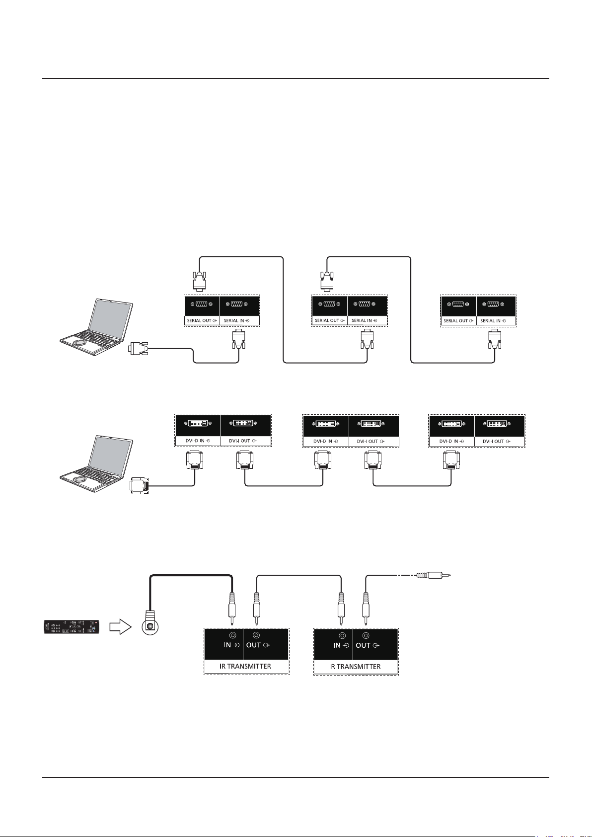
Daisy-chain Connection
External
IR Receiver
Display No.2Display No.1
Use the “connector cable of remote control”
supplied with TH-47LFV5 series
to connect next display.
You can interconnect multiple displays to create a daisy-chain conguration for video wall applications.
NOTES:
• Use the RS-232C cross cable (female) to connect the computer to this Display,and Display to Display.
• The computer shown is for example purposes only.
• A DVI cable and IR cable are attached.
• When using daisy chain, set the “TILING” menu option in the OSD “CONFIGURATION2 menu”. (see page 28)
• Up to 10 displays can be connected with a DVI daisy chain, but the number of the connected displays may be limited by a
cable signal or equipment to use.
• HDCP can be supported for up to 8 displays for a DVI daisy chain.
• Up to 25 displays can be connected with a RS-232C and IR connection daisy chain.
Display control connection (RS-232C Cable)
Display No.1 Display No.3Display No.2
[RS-232C]
Digital video connection (DVI Cable)
Display No.1 Display No.3Display No.2
[DVI]
In order to connect certainly also including the case where an L type connector is used, please tighten the screw of both ends
certainly.When the screw is not certainly being xed, connection of a daisy chain may become unstable.
External IR Connection (Optional)
With the optional “Remote Control Kit” (TY-RM50VW), you can specify the Display ID for daisy-chain connection.
19
Page 20
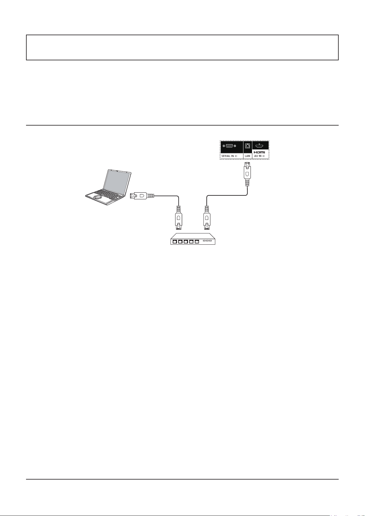
Using Network Function
This display has a network function to control the network connected display with your computer.
NOTE:
• To use the network function, set each {LAN SETTING} setting and make sure to set the {SERIAL CONTROL} to {LAN}. (see
page 21, 29)
Network Connection
Display (main unit, rear)
Hub or broadband router
NOTES:
• Make sure your broadband router or hub supports 10BASE-T/100BASE-TX.
• To connect a device using 100BASE-TX, use “Category 5 or above” LAN cable (not included).
• Touching the LAN terminal with a statically charged hand (body) may cause damage due to its discharge.
Do not touch the LAN terminal or a metal part of the LAN cable.
• For instructions on how to connect, consult your network administrator.
20
Page 21
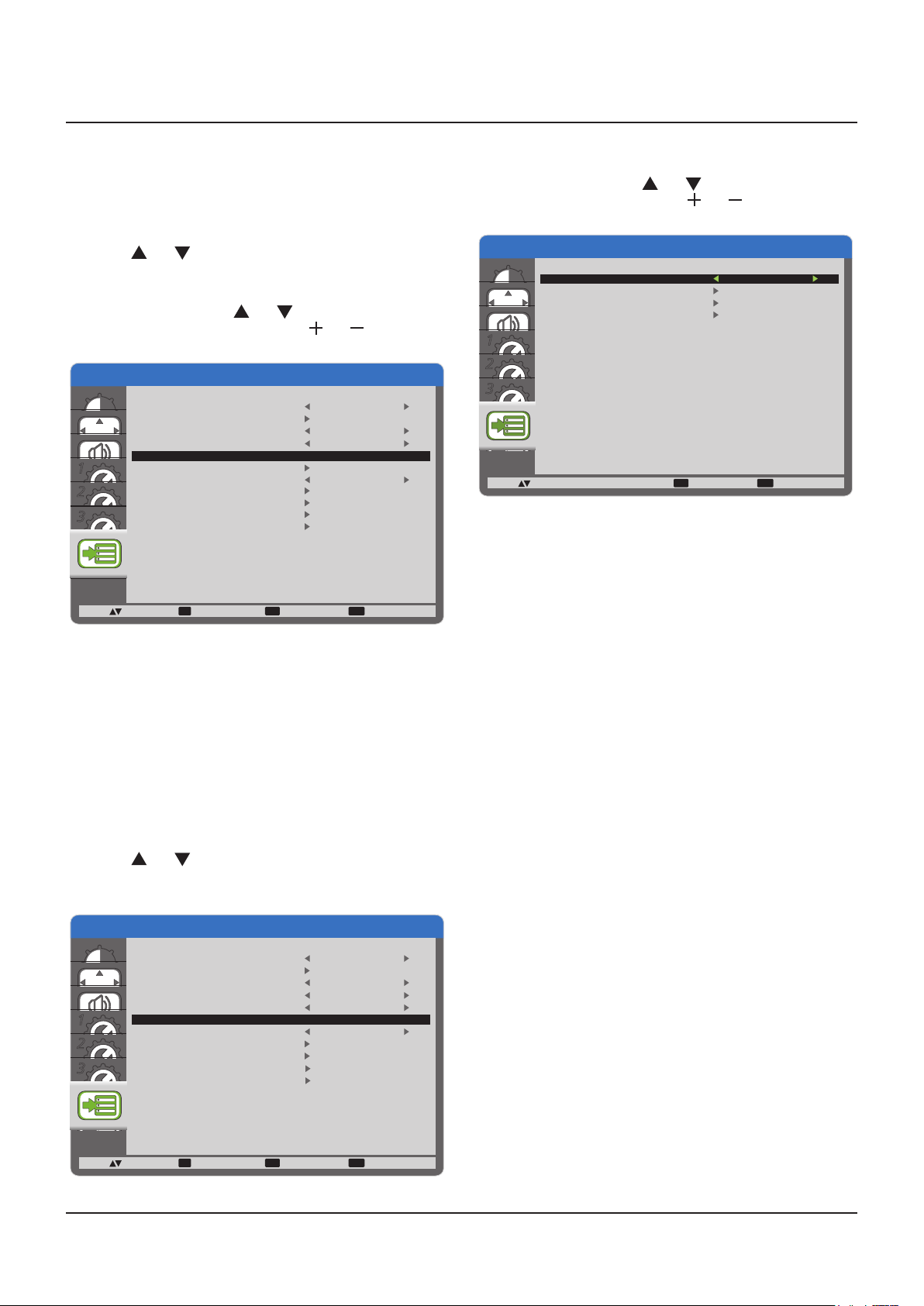
OSD Menu Setup for Network Connection
2
2
To proceed the network setting, you will have to enter the OSD menu.
SERIAL CONTROL:
Select {LAN} as the nectwork control port.
1. Press [MENU] button on this Display’s control.
2. Press [ ] or [ ] button to select the {ADVANCED
OPTION} menu.
3. Press [INPUT] button to enter the submenu.
4. In the submenu, press [ ] or [ ] button to select the
{SERIAL CONTROL} menu, press [ ] or [ ] button to
select {LAN}.
ADVANCED OPTION
1
3
INPUT CHANGE
TERMINAL SETTING
COLOR SYSTEM
SCAN MODE
SERIAL CONTROL
LAN SETTING
INITIAL INPUT
CALIBRATION DATA SAVE
CALIBRATION DATA LOAD
ADVANCED OPTION RESET
FACTORY RESET
:SEL :NEXT
SET EXIT MENU
:RETURN :EXIT MENU
NORMAL
AUTO
OVERSCAN
LAN
OFF
5. Press [MENU] button to return to the previous menu, or
press [MENU] button several times to exit the OSD menu.
LAN SETTING:
Assign {IP ADDRESS}, {SUBNET MASK}, and {DEFAULT
GATEWAY} for this Display.
NOTE:
• The {LAN SETTING} is available only after setting the
{SERIAL CONTROL} to {LAN}.
1. Press [MENU] button on this Display’s control.
2. Press [ ] or [ ] button to select the {LAN SETTING}
menu.
3. Press [INPUT] button to enter the submenu.
4. In the submenu, press [ ] or [ ] button to select the
{DHCP CLIENT} menu, press [ ] or [ ] button to select
{ON}.
ADVANCED OPTION
DHCP CLIENT
IP ADDRESS
SUBNET MASK
DEFAULT GATEWAY
LAN SETTING
ON
1
2
3
:SEL
+-:ADJ
5. Press [MENU] button to return to the previous menu, or
press [MENU] button several times to exit the OSD menu.
DHCP CLIENT
To obtain an IP address automatically using a DHCP server,
set this to {ON}. If DHCP server is not used, set this to {OFF}.
IP ADDRESS
Enter an IP address if DHCP server is not used.
SUBNET MASK
Enter a subnet mask if DHCP server is not used.
DEFAULT GATEWAY
Enter a gateway address if DHCP server is not used.
EXIT MENU
:RETURN :EXIT MENU
NOTES:
• To use a DHCP server, make sure the DHCP server is
started.
• Contact your network administrator for details on settings.
ADVANCED OPTION
1
3
INPUT CHANGE
TERMINAL SETTING
COLOR SYSTEM
SCAN MODE
SERIAL CONTROL
LAN SETTING
INITIAL INPUT
CALIBRATION DATA SAVE
CALIBRATION DATA LOAD
ADVANCED OPTION RESET
FACTORY RESET
:SEL :NEXT
SET EXIT MENU
:RETURN :EXIT MENU
NORMAL
AUTO
OVERSCAN
LAN
OFF
21
Page 22
Using Web Browser Control
You can use a Web browser to control this Display and set up a network and password.
NOTE:
• The “Web Browser Control” is currently supported with Windows IE6, IE7, or IE8.
Before Using Web Browser Control
To use the Web browser control, the Display and computer setups are required.
Dsiplay Setup
Set each {LAN SETTING} setting and make sure to set the {SERIAL CONTROL} to {LAN} (see page 21, 29).
Computer Setup (for Windows operating system)
Disable proxy server settings
1. Display [Internet Properties] window.
Click [Start] [Control Panel] [Network and Internet Connections] [Internet Options].
2. Click the [Connections] tab and then [LAN Settings].
3. Deselect the [Use automatic conguration script] and [Use a proxy server for your LAN] boxes.
4. Click [OK].
Enable JavaScript
1. Display [Internet Properties] window.
Click [Start] [Control Panel] [Network and Internet Connections] [Internet Options].
2. Set the security level on the [Security] tab to [Default Level]. Alternatively enable [Active scripting] from the [Custom
Level] button.
22
Page 23
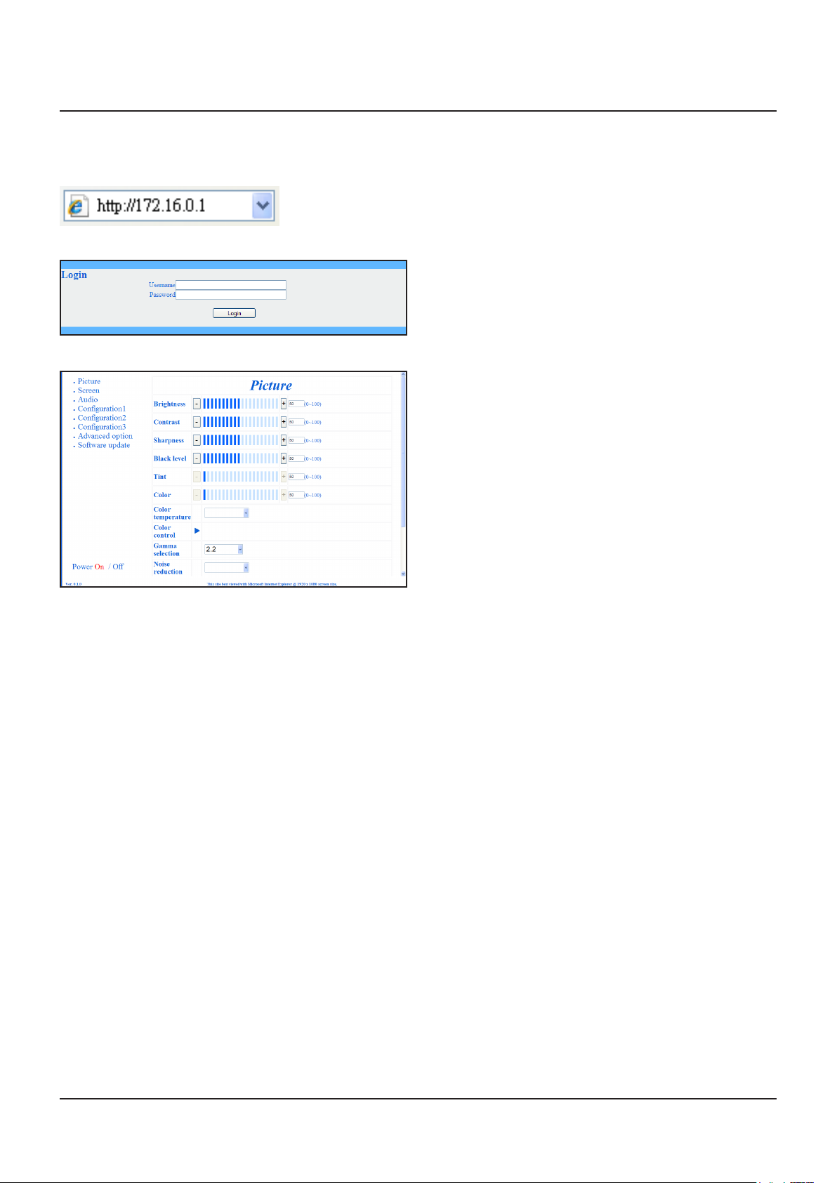
Access from Web Browser
Access to the TOP screen of the Web browser control using a Web browser.
1. Start your Web browser.
2. Enter the IP address from the {IP ADDRESS} set with the {LAN SETTING} of this Display (see page 21, 29).
3. Enter the {Username} and {Password} when the Authentication screen is displayed.
Authentication screen
4. Click [OK].
NOTES:
• Default {Username} and {Password} are as follows:
{Username}: admin
{Password}: 0000
• Panasonic Corporation and its afliated companies never directly ask customers for their password. Do not give out your
password even if directly asked by a third-party representing themselves as Panasonic Corporation.
23
Page 24
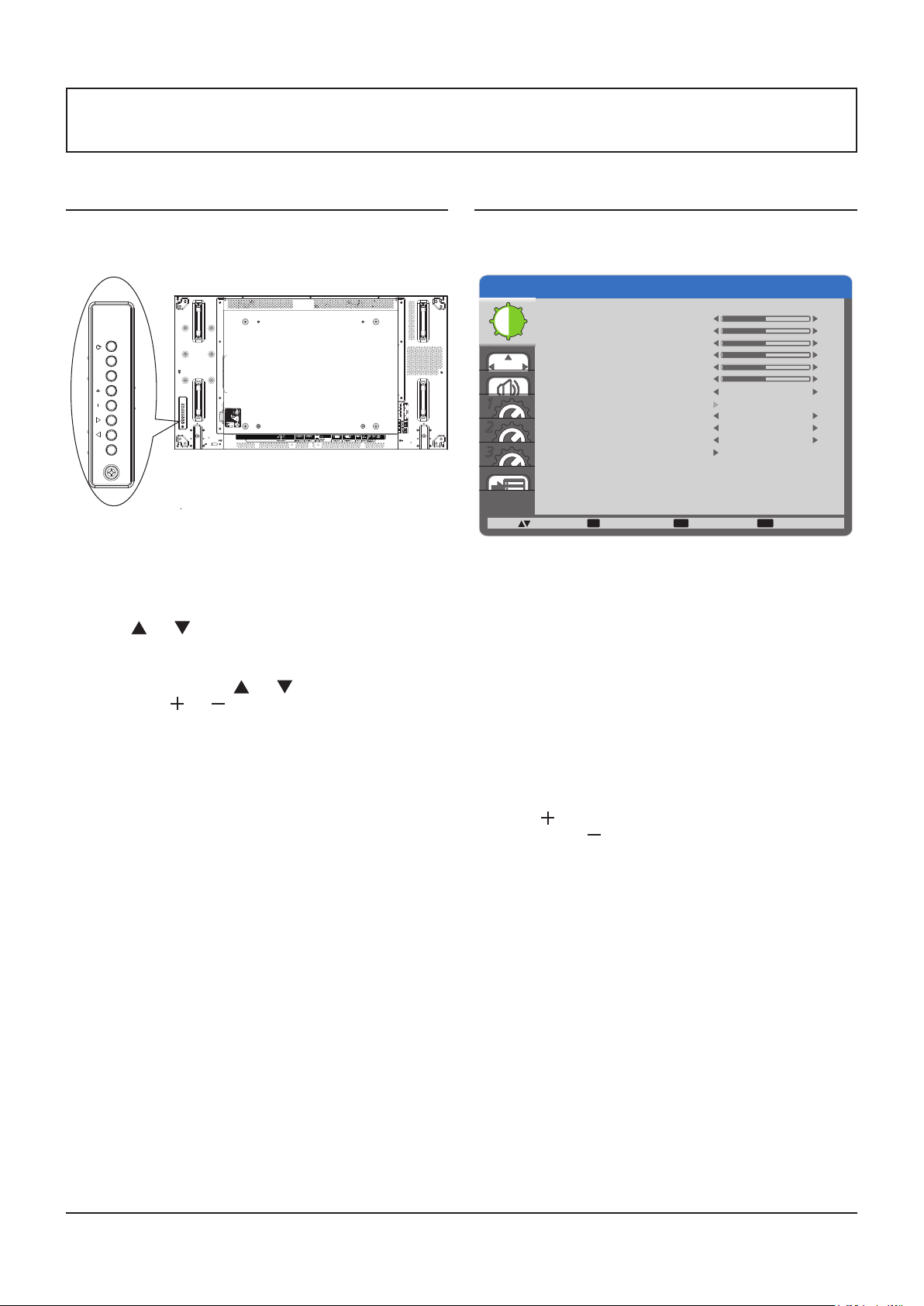
On-Screen Display Menu
Entering the OSD Menu
Using this Display’s control buttons
MUTE INPUT MENU
EXT SP(8Ω,20W[10W+10W])
1. Press [MENU] button to display the OSD menu.
2. Press [ ] or [ ] button to choose the item you want to
adjust.
3. Press [INPUT] button to enter the submenu.
4. In the submenu, press [ ] or [ ] button to toggle among
items, press [ ] or [ ] button to adjust settings. If there is
a submenu, press [INPUT] button to enter the submenu.
5. Press [MENU] button to return to the previous menu, or
press [MENU] button several times to exit the OSD menu.
OSD Menu Overview
PICTURE menu
PICTURE
BRIGHTNESS
CONTRAST
SHARPNESS
BLACK LEVEL
TINT
COLOR
1
2
3
COLOR TEMPERATURE
USER COLOR
GAMMA SELECTION NATIVE
NOISE REDUCTION
FILM MODE
PICTURE RESET
:SEL :NEXT
SET EXIT MENU
:RETURN :EXIT MENU
10000K
LOW
AUTO
BRIGHTNESS
Adjust the overall image brightness by changing the intensity
of the LCD panel’s backlight.
CONTRAST
Adjust to sharpen the picture quality. The black portions of
the picture become richer in darkness and the white become
brighter.
SHARPNESS
Adjust to improve the image detail.
BLACK LEVEL
Adjust to change the image brightness.
TINT
Press the [ ] button and the esh tone color turns slightly
purple. Press the [ ] button and the esh tone color turns
slightly green.
NOTE: This item is functional for HDMI, DVD/HD, and
VIDEO inputs only.
COLOR
Adjust to increase or decrease the intensity of colors in the
image.
NOTE: This item is functional for HDMI, DVD/HD, and
VIDEO inputs only.
COLOR TEMPERATURE
Select a color temperature for the image. A lower color
temperature will have a reddish tint, whilst a higher color
temperature gives off a more bluish tint.
The options are: {3000K} / {4000K} / {5000K} / {6500K} /
{7500K} / {9300K} / {10000K} / {NATIVE} / {USER}.
USER COLOR
With this function you can adjust the color tones of the image
precisely by changing the R (Red), G (Green) and B (Blue)
settings independently.
50
50
50
50
50
50
24
Page 25
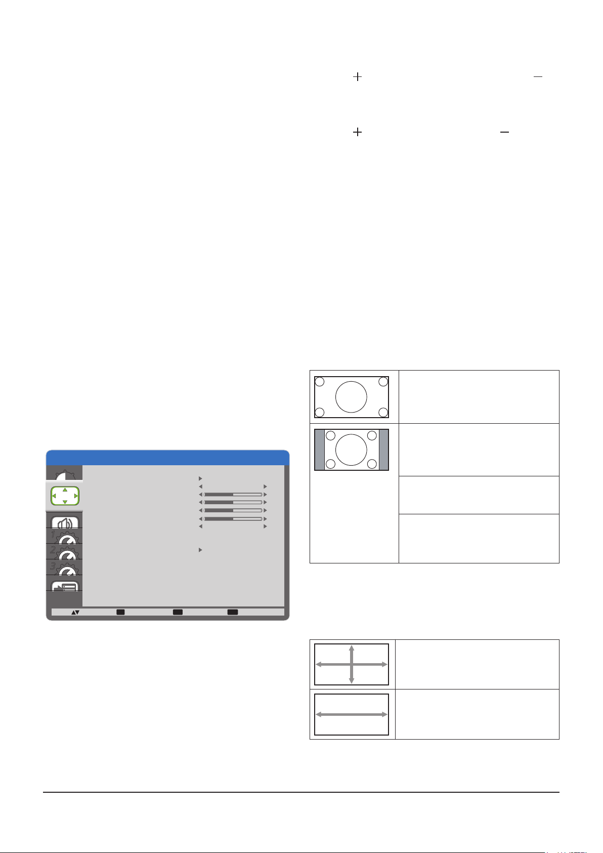
NOTE: This item is functional only when {COLOR
TEMPERATURE} is set to {USER}.
GAMMA SELECTION
Gamma is what controls the overall brightness of an image.
Images which are not corrected properly can appear too
white or too dark, so controlling the gamma properly can have
a huge inuence on the overall picture quality of your display.
The options are: {NATIVE} / {2.2} / {2.4} / {S GAMMA}.
NOISE REDUCTION
Adjust to remove the noise in the image. You can select a
suitable noise reduction level.
The options are: {OFF} / {LOW} / {MIDDLE} / {HIGH}.
NOTE: This item is functional for HDMI, DVD/HD, and
VIDEO inputs only.
FILM MODE
Choose to turn on or off the lm mode frame conversion
function.
• {AUTO} - Enable the lm mode frame conversion function
for movies and motion pictures. The display converts a
24 frames-per-second (24 fps) input signal format to DVD
video signal format.
• {OFF} - Disable the lm mode frame conversion function.
This mode is suitable for TV broadcasting and video
signals.
NOTE: This item is functional for HDMI, DVD/HD, and
VIDEO inputs only.
PICTURE RESET
Reset all settings in the Picture menu to factory preset values.
H POSITION
Press the [ ] button to move the image to the right, or [ ] to
move the image to the left.
NOTE: This item is functional for PC input only.
V POSITION
Press the [ ] button to move the image up, or [ ] to move
the image down.
NOTE: This item is functional for PC input only.
CLOCK
Adjust the width of the image.
NOTE: This item is functional for PC input only.
CLOCK PHASE
Adjust to improve the focus, clarity and stability of the image.
NOTE: This item is functional for PC input only.
ZOOM MODE
The pictures you receive may be transmitted in 16:9 format
(wide screen) or 4:3 format (conventional screen). The 16:9
pictures sometimes have a black band at the top and bottom
of the screen (letterbox format).
This function allows you to optimize the picture display on
screen. The following zoom modes are available for:
• PC mode: {FULL} / {NORMAL} / {CUSTOM} / {REAL}.
• Video mode: {FULL} / {NORMAL} / {CUSTOM} / {REAL}.
FULL
This mode restores the correct
proportions of pictures transmitted in
16:9 using the full screen display.
SCREEN menu
SCREEN
AUTO SETUP
AUTO ADJUST
H POSITION
V POSITION
CLOCK
CLOCK PHASE
ZOOM MODE
1
2
CUSTOM ZOOM
INPUT RESOLUTION
SCREEN RESET
3
:SEL :NEXT
AUTO SETUP
Use this function to let this Display automatically optimize the
display of PC input image.
NOTE: This item is functional for PC input only.
AUTO ADJUST
Choose to let this Display detect and display available signal
sources automatically.
• {ON} - Set this Display to display the image automatically
once a signal is connected.
• {OFF} - Once a signal is connected, it can only be
selected manually.
NOTE: This item is functional for PC input only.
SET EXIT MENU
:RETURN :EXIT MENU
OFF
FULL
50
50
50
50
NORMAL
The picture is reproduced in 4:3 format
and a black band is displayed on either
side of the picture.
CUSTOM
Choose to apply the custom zoom
settings in the Custom Zoom submenu.
REAL
This mode displays the image pixelby-pixel on screen without scaling the
original image size.
CUSTOM ZOOM
You can use this function to further customize the zoom
settings to suit the image you want to display.
NOTE: This item is functional only when the {ZOOM MODE}
setting is set to {CUSTOM}.
ZOOM
Expands the horizontal and vertical
sizes of the image simultaneously.
H ZOOM
Expands the horizontal size of the
image only.
25
Page 26
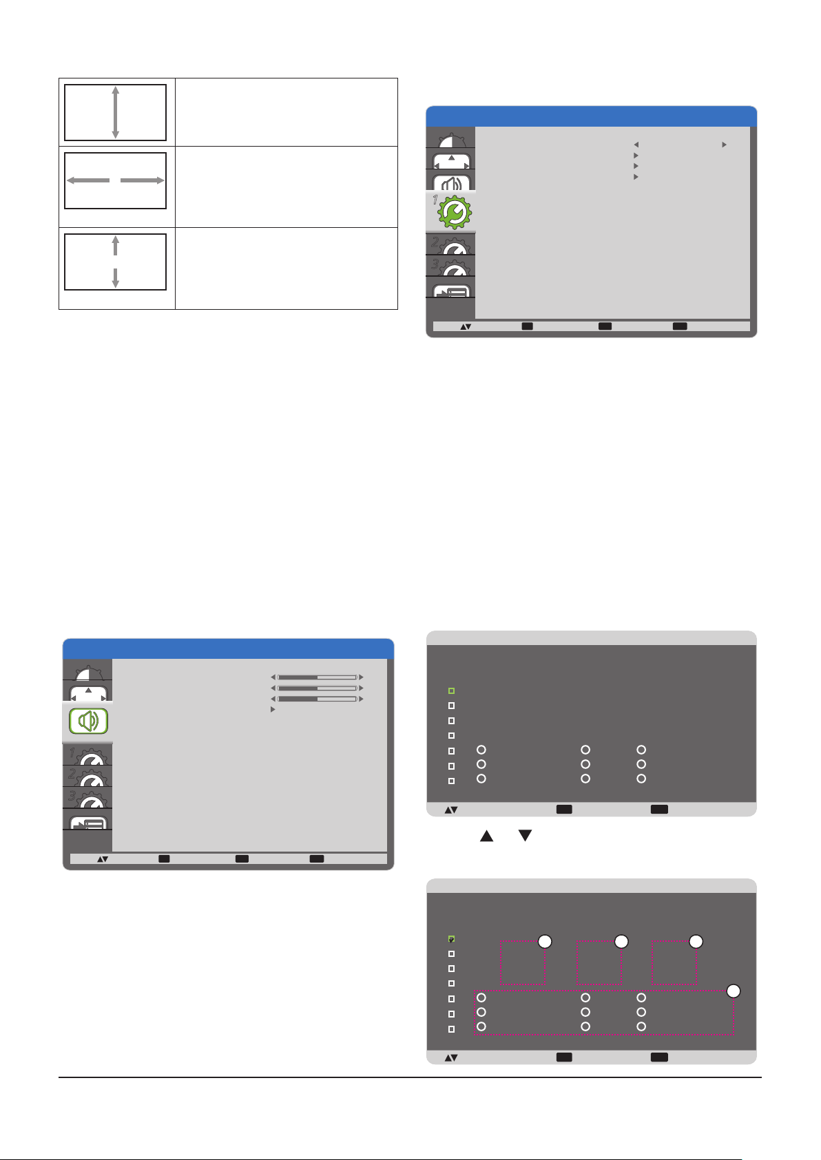
V ZOOM
SCHEDULE
SCHEDULE
Expands the vertical size of the image
only.
CONFIGURATION1 menu
CONFIGURATION1
H POSITION
Moves the horizontal position of the
image left or right.
NOTE: This item is functional for PC
input only.
V POSITION
Moves the vertical position of the image
up or down.
NOTE: This item is functional for PC
input only.
INPUT RESOLUTION
Set the resolution of the PC input. This is only required
when this Display is unable to detect the PC input resolution
correctly.
NOTE: This item is functional for PC input only.
The options are:
• {1024x768 / 1280x768 / 1360x768 / 1366x768}
• {1400x1050 / 1680x1050}
• {1600x1200 / 1920x1200}
• {Auto}: Determines the resolution automatically.
The selected settings will become effective after turning off
the power and turn it on again.
SCREEN RESET
Reset all settings in the SCREEN menu to factory preset
values.
AUDIO menu
OFF TIMER
SCHEDULE
DATE AND TIME
CONFIGURATION1 RESET
OFF
1
1
2
3
:SEL :NEXT
OFF TIMER
Set this Display to turn itself off to standby mode within an
amount of time specied.
The options are: {OFF, 1HOUR ~ 24HOURS} from currrent
time.
SCHEDULE
This function allows you to program up to 7 (seven) different
scheduled time intervals for this Display to activate.
You can select:
• The time for this Display to turn on and turn off.
• The days in a week for this Display to activate.
• Which input source this Display will use for each
scheduled activation period.
NOTE: You should set up current date and time in {DATE
AND TIME} menu before using this function.
1. Press [SET] button to enter the submenu.
SET EXIT MENU
:RETURN :EXIT MENU
AUDIO
BALANCE
TREBLE
BASS
AUDIO RESET
1
2
3
:SEL :NEXT
BALANCE
Adjust to emphasize left or right audio output balance.
TREBLE
Adjust to increase or decrease higher-pitched sounds.
BASS
Adjust to increase or decrease lower-pitched sounds.
AUDIO RESET
Reset all settings in the AUDIO menu to factory preset values.
SET EXIT MENU
:RETURN :EXIT MENU
50
50
50
TODAY
1
2
3
2012 . 01 . 11 THU 20 : 19 : 55
ON
_ :
_
OFF INPUT
_ :
_
_
4
EVERY DAY
5
6
WED
7
SAT
+-:SEL :RETURN :EXIT MENU
MON
THU
SUN
EXIT MENU
TUE
FRI
EVERY WEEK
2. Press [ ] or [ ] button to select a schedule item (item
number 1 ~ 7), and then press [SET] button to mark it the
item number.
TODAY
1
2
3
4
5
6
7
+-:SEL :RETURN :EXIT MENU
2012 . 01 . 11 THU 20 : 19 : 55
1 2 3
ON
_ :
_
EVERY DAY
WED
SAT
OFF INPUT
_ :
_
MON
THU
SUN
EXIT MENU
_
TUE
FRI
EVERY WEEK
4
26
Page 27
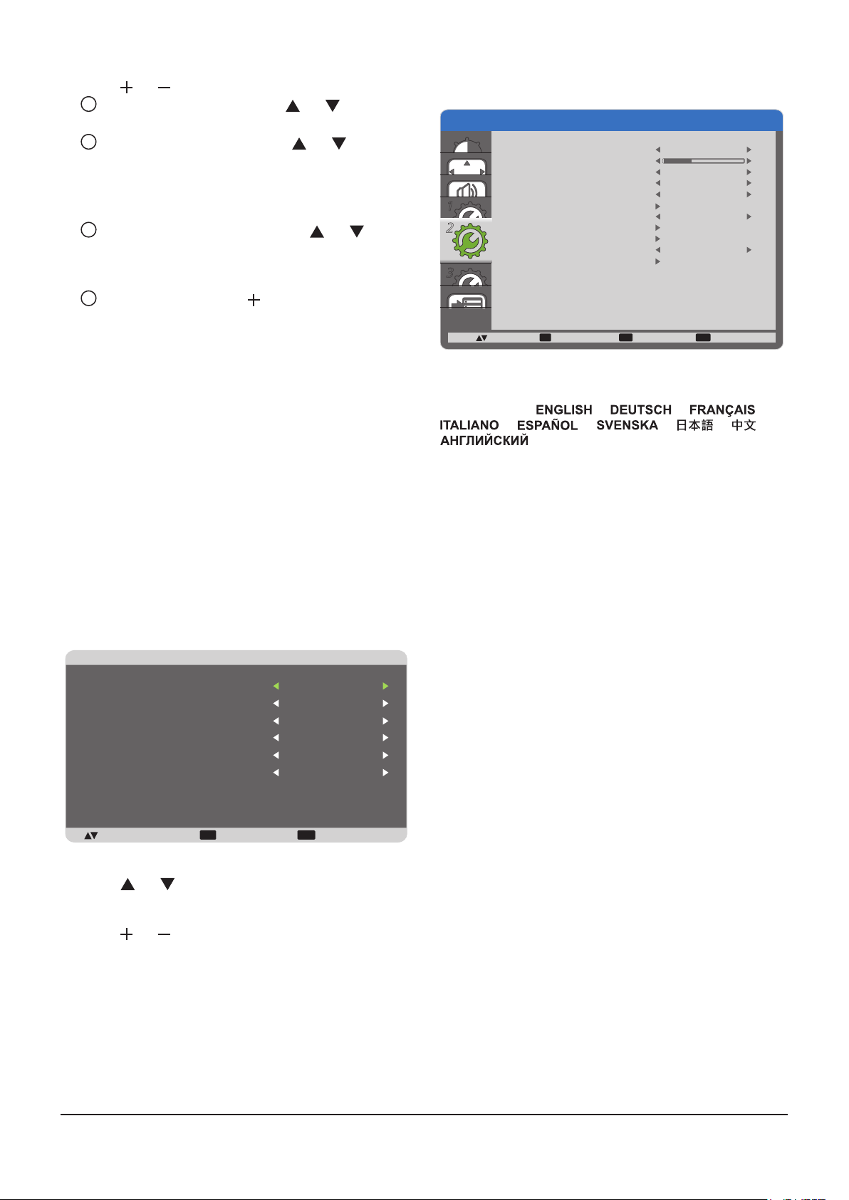
3. Press [ ] or [ ] button to select the schedule:
1
POWER-ON schedule: Press [ ] or [ ] button to
set the hour and minute for this Display to turn on.
2
POWER-OFF schedule: Press [ ] or [ ] button to
set the hour and minute for this Display to turn off.
Select or leave an empty “__” for both the hour and minute
slot if you do not want to use this power-on or power-off
schedule.
3
INPUT-SOURCE selection: Press [ ] or [ ] button
to select an input source. If no input source is
selected, the input source will remain the same as
last selected.
4
DATE schedule: Press [ ] button to select which
day in a week this schedule item will be take effect,
and then press the [SET] button.
4. For more schedule settings, press [EXIT] button and then
repeat the steps above. A check mark in the box next
to the number of the schedule item indicates that the
selected schedule is in effect.
NOTES:
• The {EVERY DAY} selection in a schedule item takes
priority over the other weekly schedules.
• If the schedule overlap, the scheduled power-on time
takes priority over scheduled power-off time.
• If there are two schedule items programmed for the same
time, the highest numbered schedule takes priority. For
example, if schedule items #1 and #2 both set this Display
to power on at 7:00 AM and off at 5:00 PM, then only
schedule item #1 will take effect.
DATE AND TIME
Adjust the current date and time for this Display’s internal
clock.
DATE AND TIME
YEAR
MONTH
DAY
HOUR
MINUTE
DAYLIGHT SAVING TIME
2012
08
04
20
20
OFF
CURRENT DATE TIME
2011.01.01 00:00:00
:SEL +-:ADJ :RETURN :EXIT MENU
EXIT MENU
1. Press [SET] button to enter the submenu.
2. Press [ ] or [ ] button to toggle among the {YEAR},
{MONTH}, {DAY}, {HOUR}, {MINUTE}, and {DAYLIGHT
SAVING TIME} settings.
3. Press [ ] or [ ] button to adjust all settings except
{DAYLIGHT SAVING TIME}.
CONFIGURATION1 RESET
Reset all settings in the CONFIGURATION1 menu to factory
preset values.
CONFIGURATION2 menu
CONFIGURATION2
LANGUAGE
OSD TURN OFF
OSD H POSITION
OSD V POSITION
INFORMATION OSD
1
2
2
MONITOR INFORMATION
MONITOR ID
IR CONTROL
TILING
POWER ON DELAY
CONFIGURATION2 RESET
3
:SEL :NEXT
LANGUAGE
Select the language used in the OSD menu.
The options are: { } / { } / { } /
{ } / { } / { } / { } / { } /
{
OSD TURN OFF
Set the period of time the OSD menu and “No Signal” stays
on the screen.
The options are: {5 ~ 120} seconds.
OSD H POSITION
Adjust the horizontal position of the OSD menu.
OSD V POSITION
Adjust the vertical position of the OSD menu.
INFORMATION OSD
Set the period of time the information OSD displayed on the
upper right corner of the screen. The information OSD will
display when input signal is changed.
The information OSD will not appear on the screen with {OFF}
selection.
The options are: {OFF, 3 SEC. ~ 10 SEC.}.
MONITOR INFORMATION
Displays the information about your display, including MODEL
NAME and SERIAL.
MONITOR ID
Set the ID number for controlling this Display via the RS232C
connection or by ID Remote Control. Each display must have
a unique ID number when multiple sets of this Display are
connected.
IR CONTROL
Select the operation mode of the remote control unit.
• {NORMAL} - All displays can be operated normally by the
remote control.
• {LOCK} - Lock the remote control function of this Display.
To unlock, press and hold the [RECALL] button on the
remote control for 5 (ve) seconds.
SET EXIT MENU
:RETURN :EXIT MENU
}.
ENGLISH
50
50
3 SEC.
1
OFF
45
27
Page 28
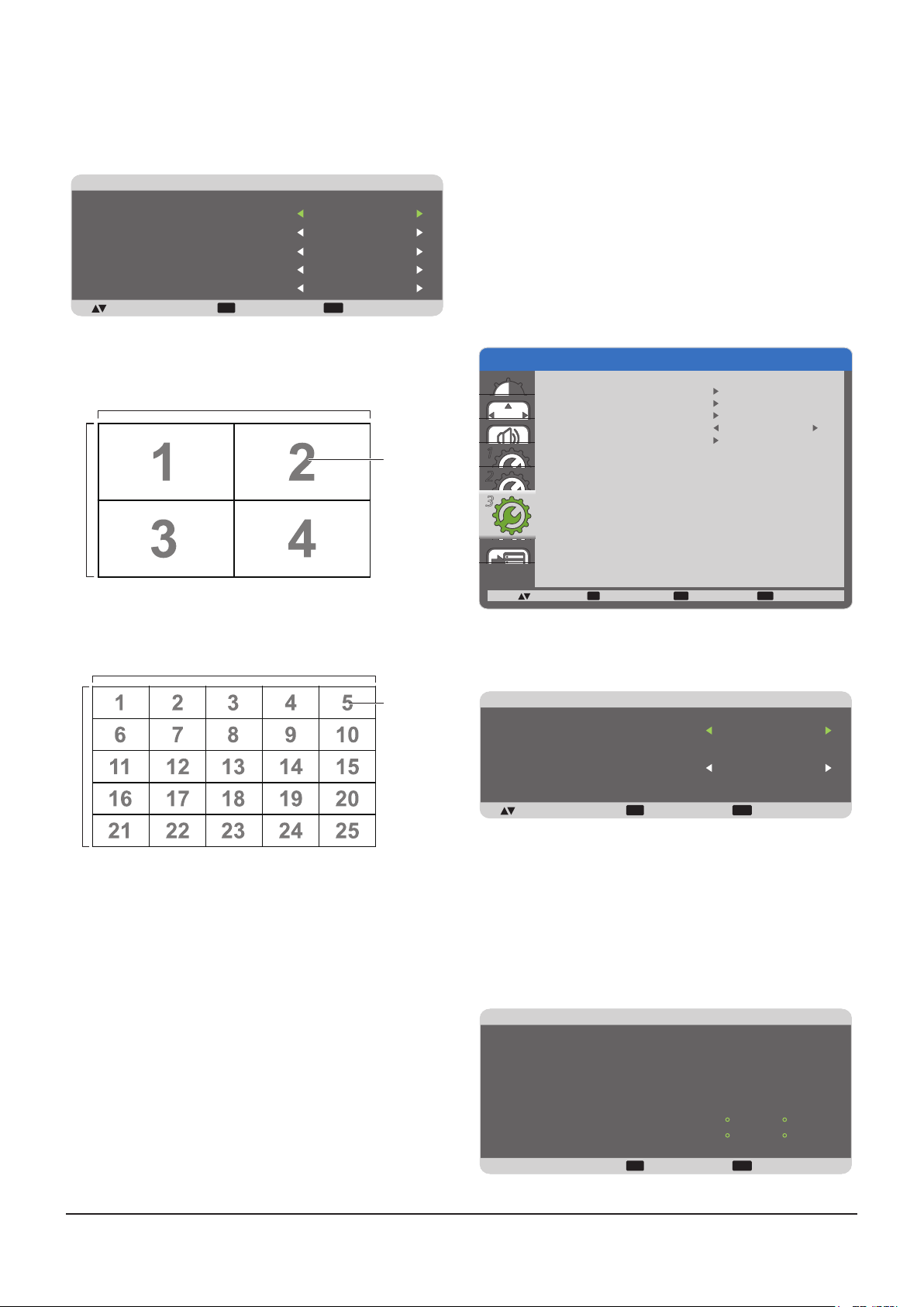
TILING
With this function you can create a single large-screen matrix
(video wall) that consists of up to 25 sets of this Display (up
to 5-set each at the vertical and horizontal side).
TILING
H MONITORS
V MONITORS
POSITION
FRAME COMP.
ENABLE
:SEL +-:ADJ :RETURN :EXIT MENU
EXIT MENU
Example: 2 x 2 screen matrix (4 displays)
H MONITORS = 2 displays
V MONITORS = 2 displays
H MONITORS
V MONITORS
1
1
1
OFF
OFF
POSITION
POWER ON DELAY
Select the delayed time until the power-on mode is activated
after the power is turned on manually or automatically. This
setting is useful in hiding start-up messages and powering on
the connected devices at different timings.
The options are: {OFF}, {2 SEC.}, {4 SEC.}, {6 SEC.},
{8 SEC.}, {10 SEC.}, {20 SEC.}, {30 SEC.}, {40 SEC.},
{50 SEC.}.
CONFIGURATION2 RESET
Reset all settings in the CONFIGURATION2 menu to factory
preset values.
CONFIGURATION3 menu
CONFIGURATION3
POWER SAVE
HEAT STATUS
SCREEN SAVER
SIDE BORDER COLOR
CONFIGURATION3 RESET
1
2
3
3
51
Example: 5 x 5 screen matrix (25 displays)
H MONITORS = 5 displays
V MONITORS = 5 displays
H MONITORS
POSITION
V MONITORS
• H MONITORS - Select the number of displays on the
horizontal side.
• V MONITORS - Select the number of displays on the
vertical side.
• POSITION - Select the position of this Display in the
screen matrix.
• FRAME COMP. - Choose to turn the frame compensation
function on or off. If turned on, this Display will adjust the
image to compensate for the width of this Display bezels
in order to accurately display the image.
• ENABLE: Choose to enable or disable the Tiling
function. If enabled, this Display will apply the settings
in {H MONITORS}, {V MONITORS}, {POSITION}, and
{FRAME COMP.}.
NOTES: A setup of TILING can be set up for each input,
individually.
:SEL :NEXT
SET EXIT MENU
:RETURN :EXIT MENU
POWER SAVE
Set this Display to reduce the power automatically.
POWER SAVE
RGB
VIDEO
:SEL +-:ADJ :RETURN :EXIT MENU
EXIT MENU
• {RGB} - Select {ON} to let this Display enter power saving
mode with no signal detected from the HDMI, DVI, or PC
inputs after 30 seconds.
• {VIDEO} - Select {ON} to let this Display enter power
saving mode with no signal detected from the VIDEO or
DVD/HD inputs after 30 minutes.
HEAT STATUS
This function allows you to check the thermal status of this
Display at any time.
HEAT STATUS
COOLING FAN
TEMPERATURE:
SENSOR 1
SENSOR 2
EXIT MENU
:RETURN :EXIT MENU
35.7 C / 96.2 F
30.2 C / 86.3 F
ON
ON
OFF
28
Page 29
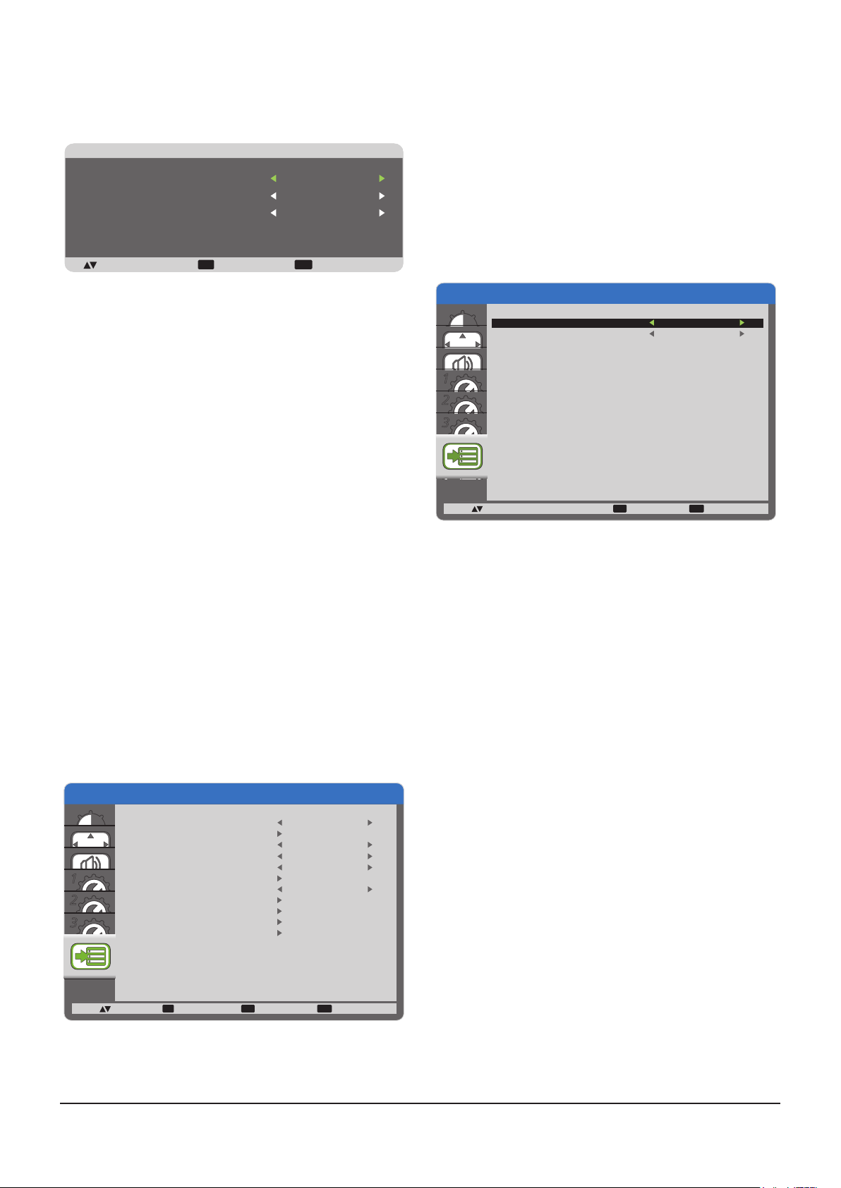
SCREEN SAVER
2
Choose to enable the panel saving functions to reduce the
risk of the “image persistence”.
SCREEN SAVER
COOLING FAN
BRIGHTNESS
MOTION
:SEL +-:ADJ :RETURN :EXIT MENU
EXIT MENU
AUTO
OFF
OFF
• {COOLING FAN} - Select {ON} to turn on the cooling fan
all the time. Select {AUTO} to turn on/off the cooling fan
according to this Display’s temperature.
NOTES:
• The default {AUTO} option will start running the cooling
fan if the temperature of 65 °C (152 °F) is reached,
and will keep running for 30 minutes after cooling
down to the temperature of 62 °C (144 °F).
• A temperature-warning message will be shown on the
screen once the temperature reaches 79 °C. All key
function except [Power] key will then be disabled.
• Once the temperature reaches 80 °C (176 °F), this
Display’s power will be shut down automatically.
• {BRIGHTNESS} - Select {ON} and the brightness of
the image will be reduced to an appropriate level, and
the Brightness setting in the Picture menu will become
unavailable.
• {MOTION} - Select the time interval ({10 ~ 900} Seconds
/ {OFF}) for this Display to slightly expand the image size
and shift the position of pixels in four directions (up, down,
left, or right).
SIDE BORDER COLOR
Adjust the brightness of the black areas displayed on both
sides of 4:3 images.
CONFIGURATION3 RESET
Reset all settings in the CONFIGURATION3 menu to factory
preset values.
ADVANCED OPTION menu
ADVANCED OPTION
INPUT CHANGE
TERMINAL SETTING
COLOR SYSTEM
SCAN MODE
SERIAL CONTROL
1
3
LAN SETTING
INITIAL INPUT
CALIBRATION DATA SAVE
CALIBRATION DATA LOAD
ADVANCED OPTION RESET
FACTORY RESET
NORMAL
AUTO
OVERSCAN
RS - 232C
OFF
TERMINAL SETTING
Select the mode to display the HDMI or DVI signal according
to their signal format depending on their source device.
• {DVI MODE}: Used for DVI-D signal.
• Select {DVI-PC} when the source device is a PC.
• Select {DVI-HD} when the source device is a video
device.
• {HDMI SIGNAL}: Used for HDMI signal.
• Select {LIMITED} when displaying the signal that uses
16 to 235 levels of 256 levels for each R, G, and B.
• Select {FULL} when displaying the signal that uses all
256 levels (from level 0 to 255).
ADVANCED OPTION
DVI-MODE
HDMI SIGNAL
TERMINAL SETTING
DVI-PC
FULL
1
2
3
:SEL +-:ADJ
COLOR SYSTEM
Selects the Color System depends on your input video format.
The options are: {AUTO} / {NTSC} / {PAL } / {SECAM} /
{4.43NTSC} / {PAL-60}.
NOTE: This item is functional for VIDEO input only.
SCAN MODE
Change this Display’s area of the image.
• {OVERSCAN} - Display about 95% of the original size of
the image. The rest of the areas surrounding the image
will be cut off.
• {UNDERSCAN} - Display the image in its original size.
NOTE: This item is functional for HDMI-Video timing input
only.
SERIAL CONTROL
Select the nectwork control port.
The options are: {RS-232C} / {LAN}.
NOTE: If {LAN} is selected, then {RS-232C} will not be
activated, even if a cable is attached, and vice versa.
EXIT MENU
:RETURN :EXIT MENU
:SEL :NEXT
SET EXIT MENU
:RETURN :EXIT MENU
INPUT CHANGE
Select the time for input switching as {NORMAL} or {QUICK}.
NOTE: The selection {QUICK} may cause a slight noise.
29
Page 30
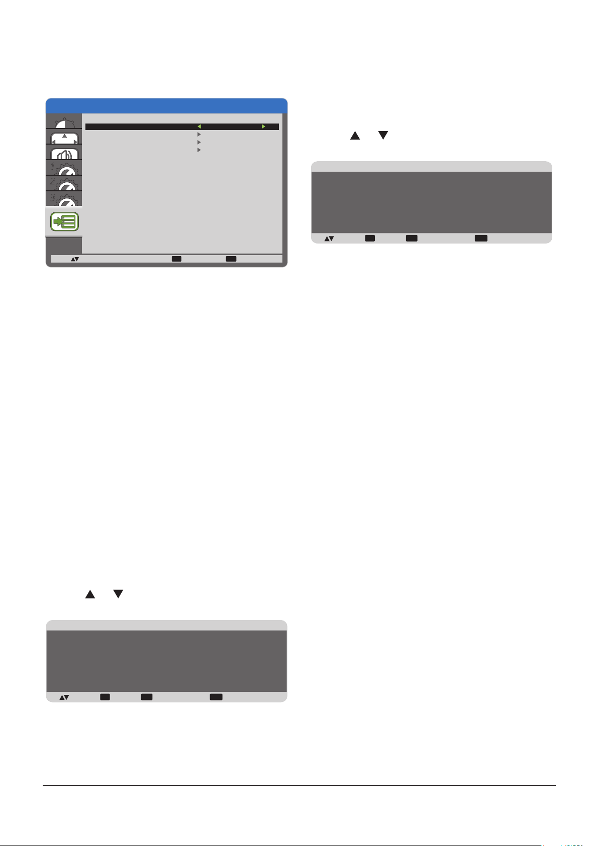
LAN SETTING
Assign {IP ADDRESS}, {SUBNET MASK}, and {DEFAULT
GATEWAY} for this Display.
ADVANCED OPTION
DHCP CLIENT
IP ADDRESS
SUBNET MASK
DEFAULT GATEWAY
LAN SETTING
OFF
FACTORY RESET
Reset all the settings in the OSD menus of {PICTURE},
{SCREEN}, {AUDIO}, {CONFIGURATION1},
{CONFIGURATION2}, {CONFIGURATION3}, and
{ADVANCED OPTION} to factory preset values.
1. Press [SET] button to enter the submenu.
2. Press [ ] or [ ] button to select {YES}, and then press
[SET] button to do the reset.
1
2
3
:SEL
+-:ADJ
• DHCP - Choose to enable or disable the DHCP function. If
enabled, this Display will be assigned IP address, Subnet
mask and Default gateway automatically. If disabled, you
will be prompted to enter the following value manually.
INITIAL INPUT
Select the input source you want this Display to initiate each
time after turning power on.
CALIBRATION DATA SAVE
Save the data of color calibration executed and adjusted by
user at any timing.
CALIBRATION DATA LOAD
By read this data, PD will get back to state at the timing when
user executed color calibration and adjusted.
Note: The data that saved and loaded by CALIBRATION
DATA SAVE and LOAD, are below items.
- The adjustment data of white balance for each “COLOR
TEMPERATURE” (3000K to 10000K, and NATIVE, USER)
- “BRIGHTNESS” data when picture mode is in STANDARD
mode
- GAMMA data for each GAMMA curve
ADVANCED OPTION RESET
Reset all settings in the ADVANCED OPTION menu to factory
preset values.
1. Press [SET] button to enter the submenu.
2. Press [ ] or [ ] button to select {YES}, and then press
[SET] button to do the reset.
EXIT MENU
:RETURN :EXIT MENU
FACTORY RESET
NO
YES
:SEL :RETURN:SET :EXIT MENU
SET
EXIT MENU
ADVANCED OPTION RESET
NO
YES
:SEL :RETURN:SET :EXIT MENU
SET
EXIT MENU
30
Page 31
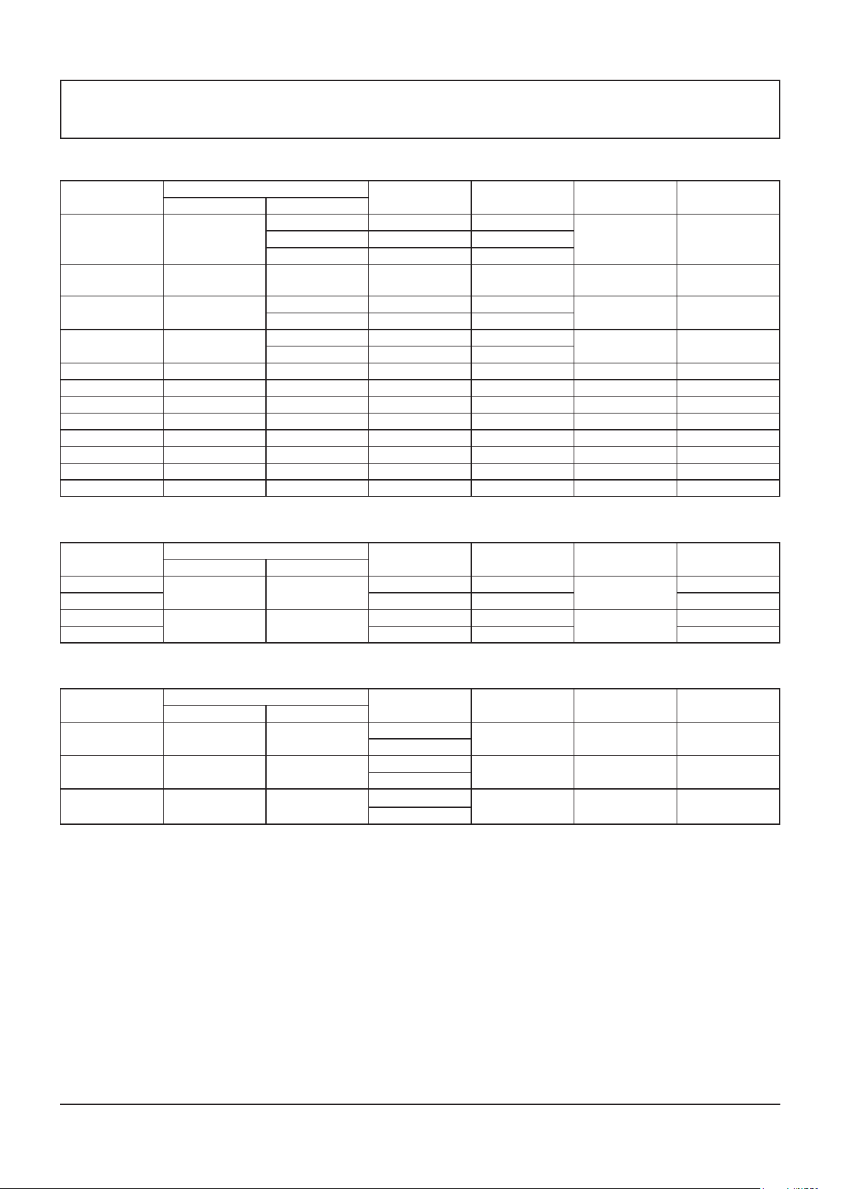
Input Mode
PC Resolution:
Standard
Resolution
VGA 640
WVGA 720 400 70 Hz 33.75 MHz 16:9
SVGA 800
XGA 1024
WXGA 1280 768 60 Hz 79.5 MHz 5:3 Wide XGA
WXGA 1280 800 60 Hz 79.5 MHz 16:10 Wide XGA
SXGA 1280 960 60 Hz 108 MHz 4:3 Super XGA
SXGA 1280 1024 60 Hz 108 MHz 5:4 Super XGA
WXGA 1360 768 60 Hz 85.5 MHz 16:9 Wide XGA
WXGA 1366 768 60 Hz 85.5 MHz 16:9 Wide XGA
UXGA 1600 1200 60 Hz 162 MHz 4:3 Ultra XGA
HD1080 1920 1080 60 Hz 148.5 MHz 16:9 HD1080
Active Resolution
H Pixels V Lines
480 60 Hz 25.175 MHz
480 72 Hz 31.5 MHz
480 75 Hz 31.5 MHz
600 60 Hz 40 MHz
600 75 Hz 49.5 MHz
768 60 Hz 65 MHz
768 75 Hz 78.75 MHz
Refresh Rate Dot Clock Aspect Ratio Stand for Mode
4:3
4:3 Super VGA
4:3
Video Graphic
Array
Wide Video
Graphic Array
Extended
Graphic Array
SDTV Resolution:
Standard
Resolution
480i
480p 59.94 Hz 27 MHz Standard
576i
576p 50 Hz 27 MHz Standard
Active Resolution
H Pixels V Lines
720 480
720 480
Refresh Rate Dot Clock Aspect Ratio Stand for Mode
29.97 Hz 13.5 MHz
25 Hz 13.5 MHz
4:3
4:3
Modied NTSC
Modied PAL
HDTV Resolution:
Standard
Resolution
720p 1280 720
1080i 1920 1080
1080p 1920 1080
• The PC text quality is optimum in HD 1080 mode (1920 x 1080, 60 Hz).
• Your PC display screen might appear different depending on the manufacture (and your particular version of Windows).
• Check your PC instruction book for information about connecting your PC to a monitor.
• If a vertical and horizontal frequency-select mode exists, select 60 Hz (vertical) and 31.5 KHz (horizontal). In some
cases, abnormal signals (such as stripes) might appear on the screen when the PC power is turned off (or if the PC is
disconnected). If so, press the [INPUT] button to enter the video mode. Also, make sure that the PC is connected.
• When horizontal synchronous signals seem irregular in RGB mode, check PC power saving mode or cable connections.
• The display settings table complies to the IBM/VESA standards, and based on the analog input.
• The DVI support mode is regarded as same to the PC support mode.
• The best timing for the vertical frequency to each mode is 60 Hz.
Active Resolution
H Pixels V Lines
Refresh Rate Dot Clock Aspect Ratio Stand for Mode
50 Hz
60 Hz
25 Hz
30 Hz
50 Hz
60 Hz
74.25 MHz 16:9
74.25 MHz 16:9
148.5 MHz 16:9
Normally DVB
Mode
Normally ATSC
Mode
Normally ATSC
Mode
31
Page 32
Cleaning and Troubleshooting
Cleaning
Caution When Using this Display
• Do not bring your hands, face or objects close to the ventilation holes of this Display. The top of this Display is usually
very hot due to the high temperature of exhaust air being released through the ventilation holes. Burns or personal
injuries may occur if any body parts are brought too close. Placing any object near the top of this Display could also result
in heat related damage to the object as well as the Display itself.
• Be sure to disconnect all cables before moving this Display. Moving this Display with its cables attached may damage the
cables and thus cause re or electric shock.
• Disconnect the power plug from the wall outlet as a safety precaution before carrying out any type of cleaning or
maintenance procedure.
Front Panel Cleaning Instructions
• The front of this Display has been specially treated. Wipe the surface gently using only a cleaning cloth or a soft, lint-free
cloth.
• If the surface becomes dirty, soak a soft, lint-free cloth in a mild detergent solution. Wring the cloth to remove excess
liquid. Wipe the surface of this Display to remove dirt. Then use a dry cloth of the same type to dry.
• Do not scratch or hit the surface of the panel with ngers or hard objects of any kind.
• Do not use volatile substances such as insert sprays, solvents and thinners.
Cabinet Cleaning Instructions
• If the cabinet becomes dirty, wipe the cabinet with a soft, dry cloth.
• If the cabinet is extremely dirty, soak a lint-free cloth in a mild detergent solution. Wring the cloth to remove as much
moisture as possible. Wipe the cabinet. Use another dry cloth to wipe over until the surface is dry.
• Do not allow any water or detergent to come into contact with the surface of this Display. If water or moisture gets inside
the unit, operating problems, electrical and shock hazards may result.
• Do not scratch or hit the cabinet with ngers or hard objects of any kind.
• Do not use volatile substances such as insert sprays, solvents and thinners on the cabinet.
• Do not place anything made from rubber or PVC near the cabinet for any extended periods of time.
32
Page 33
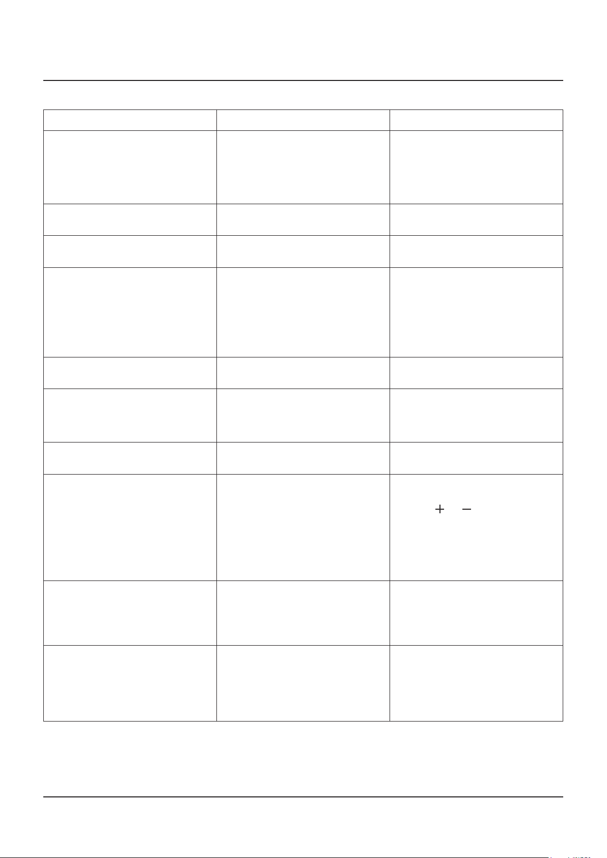
Troubleshooting
Before you call for service, determine the symptoms and make a few simple checks as shown below.
Symptom Possible Cause Remedy
No picture is displayed 1. The power cord is disconnected.
2. The main power switch on the back
of this Display is not switched on.
3. The selected input has no connection.
4. The display is in standby mode.
Interference displayed on this Display
or audible noise is heard
Color is abnormal The signal cable is not connected
Picture is distorted with abnormal
patterns
After changing input source or signal,
Picture is not displayed correctly.
Display image doesn’t ll up the full
size of the screen
Caused by surrounding electrical
appliances or uorescent lights.
properly.
1. The signal cable is not connected
properly.
2. The input signal is beyond the
capabilities of this Display.
Picture signal might be not received
correctly.
The zoom mode is not correctly set. Use the Zoom mode or Custom zoom
1. Plug in the power cord.
2. Make sure the power switch is
switched on.
3. Connect a signal connection to this
Display.
Move this Display to another location to
see is the interference is reduced.
Make sure that the signal cable is
attached rmly to the back of this Display.
1. Make sure that the signal cable is
attached rmly.
2. Check the video signal source
to see if it is beyond the range
of this Display. Please verify its
specications with this Display’s
specication section.
At once, select other input source, then
back to intended input source.
function in the Screen menu to ne tune
display geometry and time frequency
parameter.
Can hear sound, but no picture Improperly connected source signal
cable.
Can see picture but no sound is heard 1. Improperly connected source signal
cable.
2. Volume is turned all the way down.
3. [MUTE] is turned on.
4. No external speaker connected.
Some picture elements do not light up Some pixels of this Display may not turn
on.
After-Images can still be seen on this
Display after this Display is powered
off. (Examples of still pictures include
logos, video games, computer images,
and images displayed in 4:3 normal
mode)
A still picture is displayed for an over
extended period of time.
Make sure that both video inputs and
sound inputs are correctly connected.
1. Make sure that both video inputs and
sound inputs are correctly connected.
Press [ ] or [ ] button to hear
2.
sound.
3. Switch MUTE off by using the [MUTE]
button.
4. Connect external speakers and adjust
the volume to a suitable level.
This display is manufactured using
an extremely high level of precision
technology: however, sometimes some
pixels of this Display may not display.
This is not a malfunction.
Do not allow a still image to be displayed
for an extended period of time as this
can cause a permanent after-image to
remain on this Display.
33
Page 34
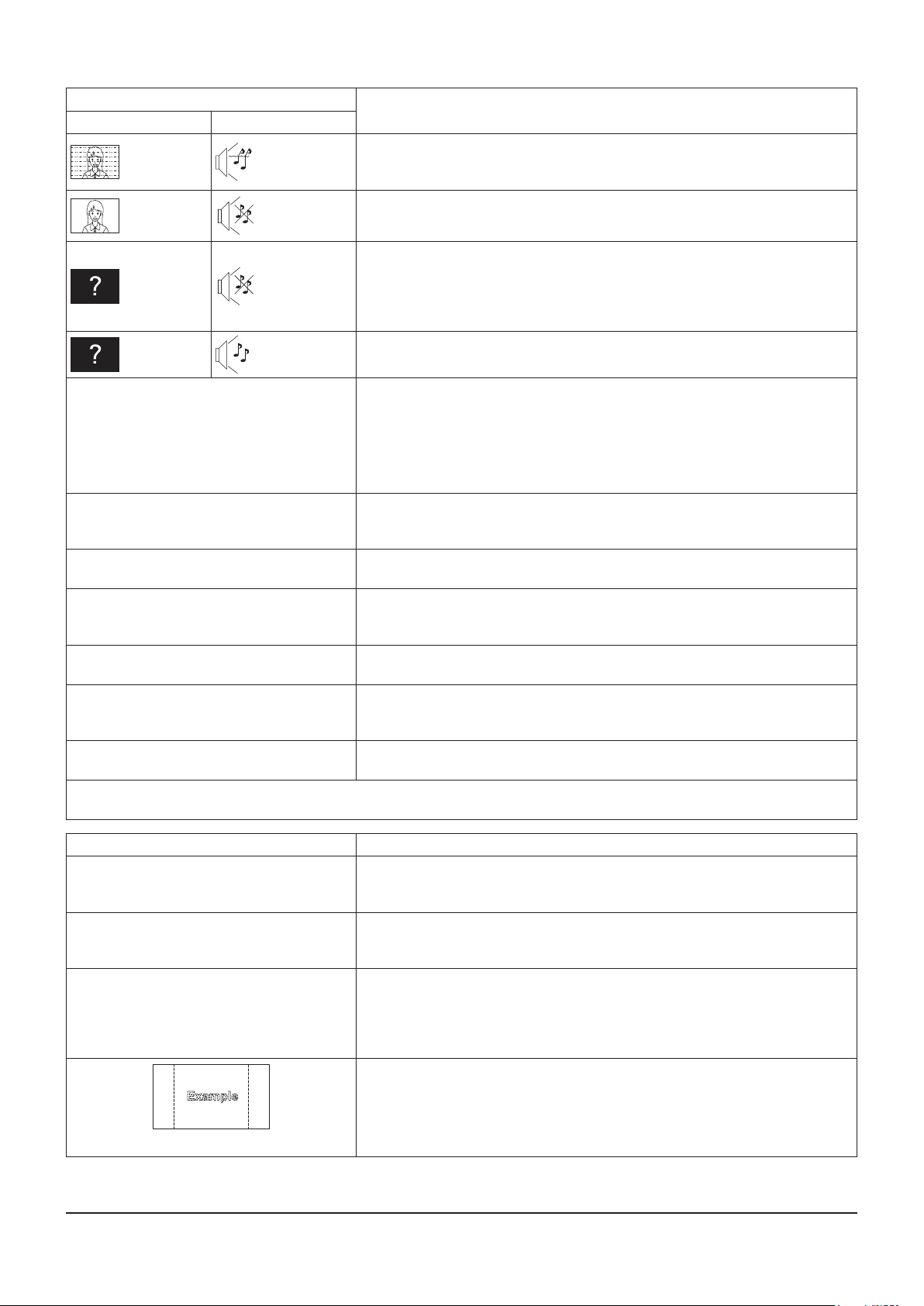
Symptoms
Picture Sound
Interference Noisy Sound
Normal
Picture
No Picture No Sound
No Sound
Checks
Electrical Appliances
Cars / Motorcycles
Fluorescent light
Volume
(Check whether the mute function has been activated on the remote control.)
Not plugged into AC outlet
Not switched on
PICTURE and BRIGHTNESS/Volume setting
(Check by pressing POWER button on this Display or on the remote control.)
No Picture
No remote control operations can be
performed.
A cracking sound is sometimes heard from
the unit.
The top or bottom of the picture on the screen
is cut off when I use the zoom function.
Areas at the top and bottom of the screen
where the image is missing appear when I
use the zoom function.
I can hear sounds coming from inside the
unit.
Parts of the unit become hot. Even when the temperature of parts of the front, top and rear panels has risen,
Power automatically turns off unexpectedly.
This LCD Display uses special image processing. Hence a slight time lag may occur between image and audio, depending on
the type of input signal. However, this is not a malfunction.
Normal
Sound
If a signal with a non-applicable color system format, or frequency is input, only
the input terminal indication is displayed.
Check whether the batteries have discharged completely and, if they have not,
whether they were inserted properly.
Check whether the remote control sensor is exposed to an outdoor light or a
strong uorescent light.
Check whether the remote control designed specically for use with the unit is
being used. (The unit cannot be operated by any other remote control.)
If there is nothing wrong with the picture or sound, this is the sound of the
cabinet undergoing very slight contractions in response to changes in the room
temperature. There are no adverse effects on the performance or other aspects.
Adjust the position of the picture on the screen.
When using a video software program (such as a cinema size program) with a
screen wider than one in the 16:9 mode, blank areas separate from the images
are formed at the top and bottom of the screen.
When the power is turned on, a sound of this Display panel being driven may
be heard: This is normal and not indicative of malfunctioning.
these temperature rises will not pose any problems in terms of performance or
quality.
Check the settings of “OFF TIMER” or “POWER SAVE”. Any of them may be
set to enable (see page 26, 28).
Symptoms Checks
It takes a while for the picture to appear. The unit digitally processes the various signals in order to reproduce esthetically
pleasing images. As such, it sometimes takes a few moments for the picture to
appear when the power has been turned on, when the input has been switched.
The edges of the images icker. Due to the characteristics of the system used to drive the panel, the edges may
appear to icker in the fast-moving parts of the images: This is normal and not
indicative of malfunctioning.
There may be red spots, blue spots, green
spots and black spots on the screen.
Image retention appears
This is a characteristic of liquid crystal panels and is not a problem. The liquid
crystal panel is built with very high precision technology giving you ne picture
details. Occasionally, a few non-active pixels may appear on the screen as
xed points of red, blue, green, or black. Please note this does not affect the
performance of your LCD.
Image retention may occur. If you display a still picture for an extended period,
the image might remain on the screen. However, it will disappear after a while.
This is not considered as malfunction.
34
Page 35
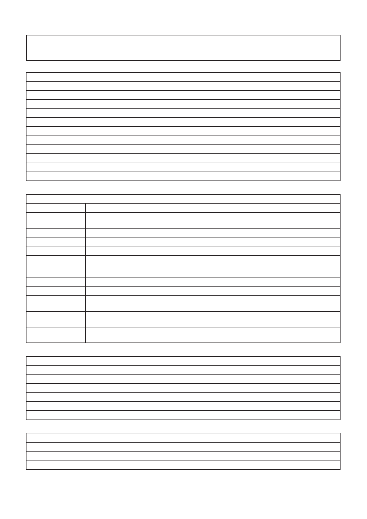
Technical Specifications
Display:
Item Specications
Screen Size 47” LCD
Active Screen Size 46.96 inches (1192.87 mm) diagonal
Aspect Ratio 16:9
Number of pixels 1920 (H) x 1080 (V)
Pixel Pitch 0.5415 (H) x 0.5415 (V) [mm],0.0213(H) x 0.0213(V)[inch]
Displayable Colors 10 Bit (D), 1.06 Billion colors
Brightness (typical) 500 cd/m2
Contrast Ratio (typical) 1400:1
Viewing Angle Up 89 / Down 89 / Left 89 / Right 89 ( typ ) @ CR > 10
Panel Life Time 60,000 h (typ)
Surface Treatment Anti-Glare
In/Out Terminals:
Item Specications
Speaker Output External Speaker 10 W + 10 W (8 Ω)
Audio Input RCA Jack x 2
3.5 mm Stereo x 1
Audio Output
RS232C D-Sub Jack x 2 (9 pin) TXD + RXD (1:1)
RJ-45 RJ-45 Jack x 1 (8 pin) 10/100 LAN Port
HDMI Input HDMI Jack x 1
DVI-D Input DVI-D jack MAX: 1920 x 1080 / 60 Hz (WUXGA)
DVI-I Output DVI-I jack Pass-through from DVI-D Input
PC Input D-Sub Jack x 1
Component Input BNC Jack x 3 Y: 1 V [p-p] (75 Ω), Pb: 0.7 V [p-p] (75Ω), Pr: 0.7 V [p-p] (75 Ω)
Composite Input BNC Jack x 1
RCA Jack x 2 0.5 V [rms] (Normal) / 2 Channel (L+R)
(Type A) (18 pin)
(15 pin)
(shared with Component-Y)
0.5 V [rms] (Normal) / 2 Channel (L+R)
Video : 480i, 480p, 720p, 1080i, 1080p
Audio: 32 kHz, 44.1 kHz, 48 kHz / 2 Channel (L+R)
Supports LPCM only
Analog RGB: 0.7 V [p-p] (75 Ω), H/CS/V: TTL (2.2 kΩ), SOG: 1 V [p-p] (75 Ω)
MAX: 1920 x 1080 / 60 Hz (WUXGA)
MAX: 480i, 576i, 480p, 576p, 720p, 1080i, 1080p
Video: 1 V [p-p] (75 Ω)
MAX: 480i, 576i
General:
Item Specications
Power Supply 110 - 127 V AC, 50/60 Hz
Power Consumption (Max) 160 W
Power Consumption (Standby) < 0.5 W
Power Consumption (Saving) < 2 W
Dimensions [W x H x D] 1044.88x 590 x 108.8 mm,41.15”*23.23”*4.28”inch
Weight 25 kg, 55lbs
Operating Condition:
Item Specications
Temperature 0 ~ 40 °C, 32 ~ 104 °F
Humidity 10 ~ 90 % RH (No condensation)
Altitude 0 ~ 2,000 m
35
Page 36
USA Only:
Disposal may be regulated in your community due to environmental
considerations. For disposal or recycling information, please visit
Panasonic website: http://www.panasonic.com/environmental or call
1-888-769-0149.
Customer’s Record
The model number and serial number of this product can be found on its back cover. You should note this serial
number in the space provided below and retain this book, plus your purchase receipt, as a permanent record of
your purchase to aid in identication in the event of theft or loss, and for Warranty Service purposes.
Model Number Serial Number
© Panasonic Corporation 2014
Panasonic Solutions Company
Unit of Panasonic Corporation of North America
Executive Ofce :
Two Riverfront Plaza, Newark, NJ 07102-5490 U.S.A
Panasonic Canada Inc.
5770 Ambler Drive
Mississauga, Ontario
L4W 2T3
 Loading...