

Panasonic TH-47LF30ER, TH-42LF30ER User Manual

Operating Instructions
FULL HD LCD Display
Model No.
TH-42LF30ER
TH-47LF30ER
English
h
Please read these instructions before operating your set
and retain them for future reference.

Dear Panasonic Customer
Welcome to the Panasonic family of customers. We hope that you will have many years of
enjoyment from your new LCD Display.
To obtain maximum benefit from your set, please read these Instructions before making
any adjustments, and retain them for future reference.
Retain your purchase receipt also, and note down the model number and serial number of
your set in the space provided on the rear cover of these instructions.
Visit our Panasonic Web Site http://panasonic.net
Table of Contents
Important Safety Notice ........................................... 3
Safety Precautions ................................................... 4
Accessories .............................................................. 7
Accessories Supply ................................................. 7
Remote Control Batteries ........................................ 7
Connections .............................................................. 8
AC cord connection and ¿ xing ................................. 8
Video equipment connection ................................... 8
VIDEO, COMPONENT / RGB IN
and HDMI connection .............................................. 9
DVI-D IN, DVI-D OUT connection ......................... 10
PC Input Terminals connection ...............................11
SERIAL Terminals connection ............................... 12
Power On / Off ......................................................... 14
Selecting the input signal ...................................... 16
Basic Controls ........................................................ 17
ASPECT Controls ................................................... 19
Digital Zoom ............................................................ 20
On-Screen Menu Displays ..................................... 21
Adjusting Pos. /Size ............................................... 22
Picture Adjustments ............................................... 24
Advanced settings ................................................. 25
Sound Adjustment .................................................. 26
SDI Sound Output ................................................. 26
PRESENT TIME Setup / Set up TIMER .................. 27
PRESENT TIME Setup .......................................... 27
Set up TIMER ........................................................ 28
Screensaver (For preventing image retention) .... 29
Setup of Screensaver Time ................................... 30
Wobbling ................................................................. 30
No activity power off .............................................. 31
ECO Mode settings ................................................. 32
Customizing the Input labels ................................. 33
Selecting the On-Screen Menu Language ............ 34
Customizing the On-Screen Menu Display .......... 34
Setup for MULTI DISPLAY ...................................... 35
How to Setup MULTI DISPLAY ............................. 35
ID Remote Control Function .................................. 36
Setup for Input Signals .......................................... 37
Component / RGB-in select ................................... 37
YUV / RGB-in select .............................................. 37
Signal menu .......................................................... 38
3D Y/C Filter .......................................................... 38
Colour system ....................................................... 39
Cinema reality ....................................................... 39
XGA Mode ............................................................. 39
Noise reduction ..................................................... 40
Sync ...................................................................... 40
HDMI Range .......................................................... 40
Input signal display ................................................ 41
Options Adjustments ............................................. 42
Troubleshooting ..................................................... 45
Applicable Input Signals ........................................ 46
Shipping condition ................................................. 48
Speci¿ cations ......................................................... 49
Trademark Credits
• VGA is a trademark of International Business Machines Corporation.
• Macintosh is a registered trademark of Apple Inc., USA.
• SVGA, XGA, SXGA and UXGA are registered trademarks of the Video Electronics Standard Association.
Even if no special notation has been made of company or product trademarks, these trademarks have been fully respected.
• HDMI, the HDMI Logo, and High-De¿ nition Multimedia Interface are trademarks or registered trademarks of HDMI
Licensing LLC in the United States and other countries.
Note:
Image retention may occur. If you display a still picture for an extended period, the image might remain on the screen.
However, it will disappear after a while.
2
Important Safety Notice
IMPORTANT: THE MOULDED PLUG
WARNING
1) To prevent damage which may result in ¿ re or shock hazard, do not expose this appliance to dripping
or splashing.
Do not place containers with water (À ower vase, cups, cosmetics, etc.) above the set. (including on
shelves above, etc.)
No naked À ame sources, such as lighted candles, should be placed on / above the set.
2) To prevent electric shock, do not remove cover. No user serviceable parts inside. Refer servicing to quali¿ ed
service personnel.
3) Do not remove the earthing pin on the power plug. This apparatus is equipped with a three pin earthing-type
power plug. This plug will only ¿ t an earthing-type power outlet. This is a safety feature. If you are unable to
insert the plug into the outlet, contact an electrician.
Do not defeat the purpose of the earthing plug.
4) To prevent electric shock, ensure the earthing pin on the AC cord power plug is securely connected.
CAUTION
This appliance is intended for use in environments which are relatively free of electromagnetic ¿ elds.
Using this appliance near sources of strong electromagnetic ¿ elds or where electrical noise may overlap with the
input signals could cause the picture and sound to wobble or cause interference such as noise to appear.
To avoid the possibility of harm to this appliance, keep it away from sources of strong electromagnetic ¿ elds.
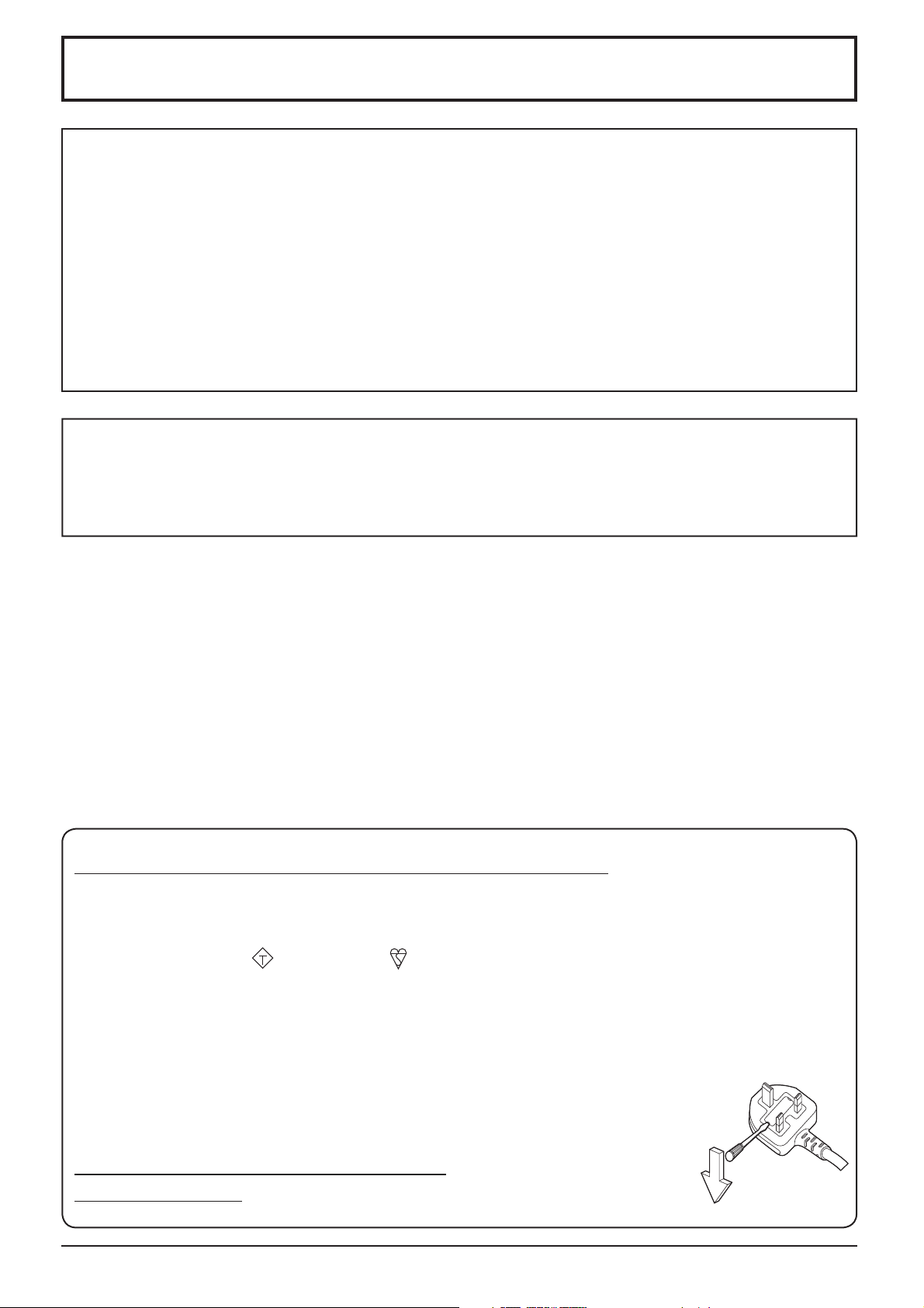
FOR YOUR SAFETY, PLEASE READ THE FOLLOWING TEXT CAREFULLY.
This display is supplied with a moulded three pin mains plug for your safety and convenience. A 10 amp fuse is
¿ tted in this plug. Shall the fuse need to be replaced, please ensure that the replacement fuse has a rating of 10
amps and that it is approved by ASTA or BSI to BS1362.
Check for the ASTA mark
If the plug contains a removable fuse cover, you must ensure that it is re¿ tted when the fuse is replaced.
If you lose the fuse cover the plug must not be used until a replacement cover is obtained.
A replacement fuse cover can be purchased from your local Panasonic dealer.
Do not cut off the mains plug.
Do not use any other type of mains lead except the one supplied with this display.
The supplied mains lead and moulded plug are designed to be used with this display to avoid
interference and for your safety.
If the socket outlet in your home is not suitable, get it changed by a quali¿ ed electrician.
If the plug or mains lead becomes damaged, purchase a replacement from an authorized dealer.
WARNING : — THIS DISPLAY MUST BE EARTHED.
How to replace the fuse.
IMPORTANT: THE MOULDED PLUG
or the BSI mark on the body of the fuse.
ASA
Open the fuse compartment with a screwdriver and replace the fuse.
3

Safety Precautions
WARNING
Setup
This LCD Display is for use only with the following optional accessories. Use with any other type of optional
accessories may cause instability which could result in the possibility of injury.
(All of the following accessories are manufactured by Panasonic Corporation.)
• Pedestal ....................................................... TY-ST20-K
• HD-SDI Terminal Board with audio .............. TY-FB10HD
Always be sure to ask a quali¿ ed technician to carry out set-up.
Small parts can present choking hazard if accidentally swallowed. Keep small parts away from young children. Discard
unneeded small parts and other objects, including packaging materials and plastic bags/sheets to prevent them from
being played with by young children, creating the potential risk of suffocation.
Do not place the Display on sloped or unstable surfaces, and ensure that the Display does not hang over the
edge of the base.
• The Display may fall off or tip over.
Do not place any objects on top of the Display.
• If water is spills onto the Display or foreign objects get inside it, a short-circuit may occur which could result in ¿ re
or electric shock. If any foreign objects get inside the Display, please consult your local Panasonic dealer.
Transport only in upright position!
• Transporting the unit with its display panel facing upright or downward may cause damage to the internal
circuitry.
Ventilation should not be impeded by covering the ventilation openings with items such as newspapers, table
cloths and curtains.
For suf¿ cient ventilation;
Leave a space of 10 cm or more at the top, left and right, and 5 cm or more at the rear, and also keep the space
between the bottom of the display and the À oor surface.
Cautions for Wall Installation
• Wall installation should be performed by an installation professional. Installing the Display incorrectly may lead to
an accident that results in death or serious injury. Furthermore, when installing on a wall, a wall hanging bracket
that conforms to VESA standards (VESA 400 × 400) must be used.
• When installing the Display vertically, be sure to install the power indicator onto the bottom of the Display.
4

Safety Precautions
When using the LCD Display
The Display is designed to operate on 220 - 240 V AC, 50/60 Hz.
Do not cover the ventilation holes.
• Doing so may cause the Display to overheat, which can cause ¿ re or damage to the Display.
Do not stick any foreign objects into the Display.
• Do not insert any metal or À ammable objects into the ventilations holes or drop them onto the Display, as doing so
can cause ¿ re or electric shock.
Do not remove the cover or modify it in any way.
• High voltages which can cause severe electric shocks are present inside the Display. For any inspection, adjustment
and repair work, please contact your local Panasonic dealer.
Ensure that the mains plug is easily accessible.
An apparatus with CLASS I construction shall be connected to a mains socket outlet with a protective earthing connection.
Do not use any power supply cord other than that provided with this unit.
• Doing so may cause ¿ re or electric shocks.
Securely insert the power supply plug as far as it will go.
• If the plug is not fully inserted, heat may be generated which could cause ¿ re. If the plug is damaged or the wall
socket is loose, they shall not be used.
Do not handle the power supply plug with wet hands.
• Doing so may cause electric shocks.
Do not do anything that may damage the power cable. When disconnecting the power cable, pull on the plug body, not the cable.
• Do not damage the cable, make any modi¿ cations to it, place heavy objects on top of it, heat it, place it near any
hot objects, twist it, bend it excessively or pull it. To do so may cause ¿ re and electric shock. If the power cable is
damaged, have it repaired at your local Panasonic dealer.
If the Display is not going to be used for any prolonged length of time, unplug the power supply plug from
the wall outlet.
To prevent the spread of ¿ re, keep candles or other open À ames away from this product at all times.
If problems occur during use
If a problem occurs (such as no picture or no sound), or if smoke or an abnormal odour starts to come out
from the Display, immediately unplug the power supply plug from the wall outlet.
• If you continue to use the Display in this condition, ¿ re or electric shock could result. After checking that the smoke
has stopped, contact your local Panasonic dealer so that the necessary repairs can be made. Repairing the Display
yourself is extremely dangerous, and shall never be done.
If water or foreign objects get inside the Display, if the Display is dropped, or if the cabinet becomes damages,
disconnect the power supply plug immediately.
A short circuit may occur, which could cause ¿ re. Contact your local Panasonic dealer for any repairs that need to be made.
•
5

Safety Precautions
CAUTION
When using the LCD Display
Do not bring your hands, face or objects close to the ventilation holes of the Display.
• Heated air comes out from the ventilation holes at the top of Display will be hot. Do not bring your hands or face,
or objects which cannot withstand heat, close to this port, otherwise burns or deformation could result.
Be sure to disconnect all cables before moving the Display.
• If the Display is moved while some of the cables are still connected, the cables may become damaged, and ¿ re or
electric shock could result.
Disconnect the power supply plug from the wall socket as a safety precaution before carrying out any
cleaning.
• Electric shocks can result if this is not done.
Clean the power cable regularly to prevent it becoming dusty.
• If dust built up on the power cord plug, the resultant humidity can damage the insulation, which could result in ¿ re.
Pull the power cord plug out from the wall outlet and wipe the mains lead with a dry cloth.
Do not burn or breakup batteries.
• Batteries must not be exposed to excessive heat such as sunshine, ¿ re or the like.
Cleaning and maintenance
The front of the display panel has been specially treated. Wipe the panel surface gently using only a cleaning
cloth or a soft, lint-free cloth.
• If the surface is particularly dirty, wipe with a soft, lint-free cloth which has been soaked in pure water or water in
which neutral detergent has been diluted 100 times, and then wipe it evenly with a dry cloth of the same type until
the surface is dry.
• Do not scratch or hit the surface of the panel with ¿ ngernails or other hard objects, otherwise the surface may
become damaged. Furthermore, avoid contact with volatile substances such as insect sprays, solvents and thinner,
otherwise the quality of the surface may be adversely affected.
If the cabinet becomes dirty, wipe it with a soft, dry cloth.
• If the cabinet is particularly dirty, soak the cloth in water to which a small amount of neutral detergent has been
added and then wring the cloth dry. Use this cloth to wipe the cabinet, and then wipe it dry with a dry cloth.
• Do not allow any detergent to come into direct contact with the surface of the Display. If water droplets get inside
the unit, operating problems may result.
• Avoid contact with volatile substances such as insect sprays, solvents and thinner, otherwise the quality of the
cabinet surface may be adversely affected or the coating may peel off. Furthermore, do not leave it for long periods
in contact with articles made from rubber or PVC.
Usage of a chemical cloth
• Do not use a chemical cloth for the panel surface.
• Follow the instructions for the chemical cloth to use it for the cabinet.
6
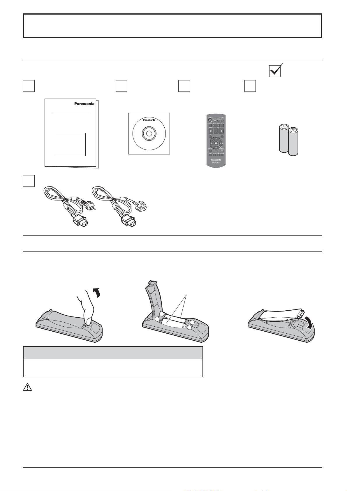
Accessories
Accessories Supply
Check that you have the accessories and items shown
Operating Instruction book
Power supply cord
CD-ROM
(Operating
instructions)
Remote Control Batteries
Remote Control
Transmitter
N2QAYB000691
Batteries for the Remote
Control Transmitter
(R6 (UM3) Size × 2)
Requires two R6 batteries.
1. Pull and hold the hook, then open
the battery cover.
2. Insert batteries - note correct
polarity ( + and -).
“R6 (UM3)” size
-
+
+
-
3. Replace the cover.
Helpful Hint:
For frequent remote control users, replace old batteries with Alkaline
batteries for longer life.
Precaution on battery use
Incorrect installation can cause battery leakage and corrosion that will damage the remote control transmitter.
Disposal of batteries should be in an environment-friendly manner.
Observe the following precaution:
1. Batteries shall always be replaced as a pair. Always use new batteries when replacing the old set.
2. Do not combine a used battery with a new one.
3. Do not mix battery types (example: “Zinc Carbon” with “Alkaline”).
4. Do not attempt to charge, short-circuit, disassemble, heat or burn used batteries.
Battery replacement is necessary when remote control acts sporadically or stops operating the Display set.
5.
6. Do not burn or breakup batteries.
Batteries must not be exposed to excessive heat such as sunshine, ¿ re or the like.
7
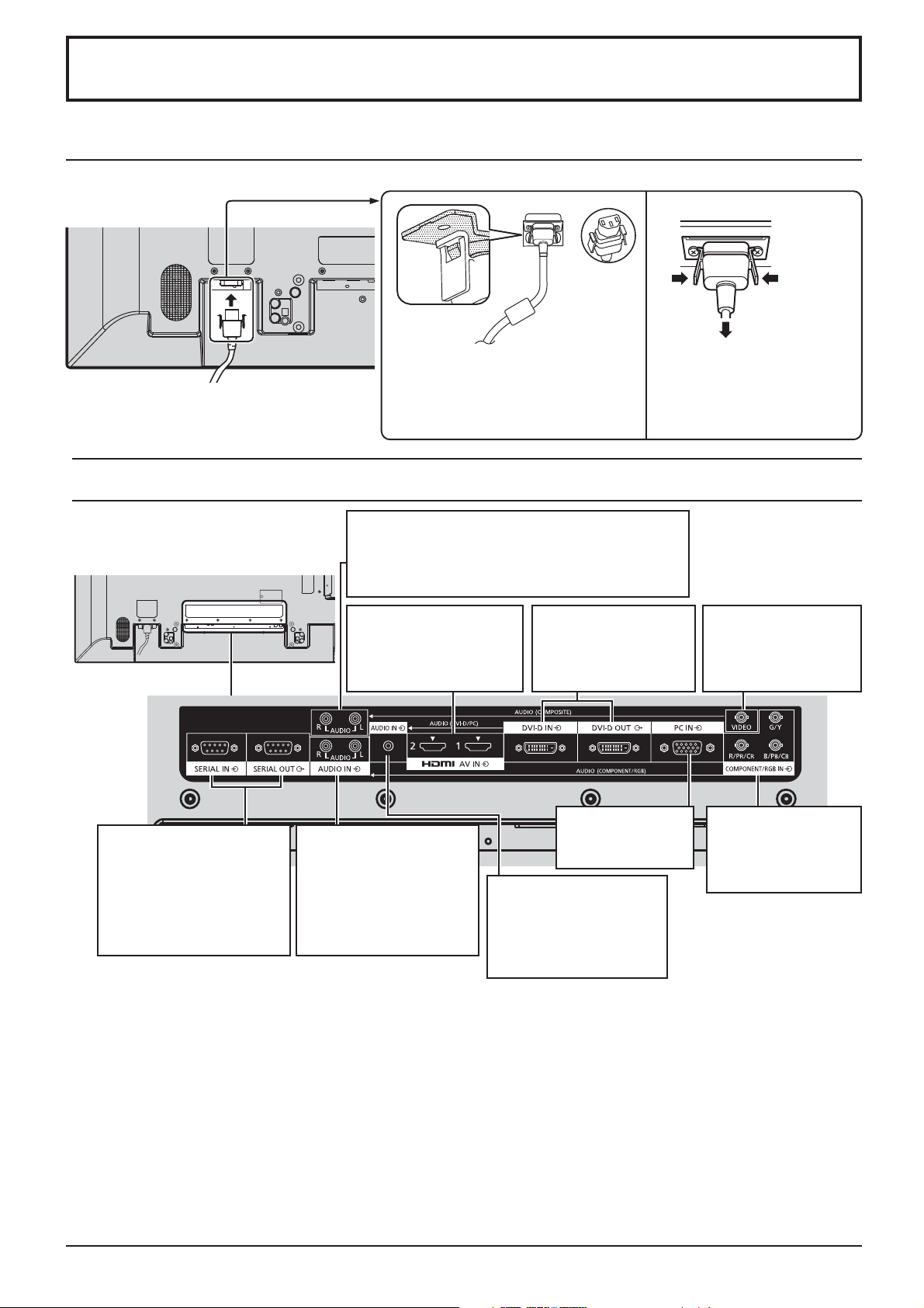
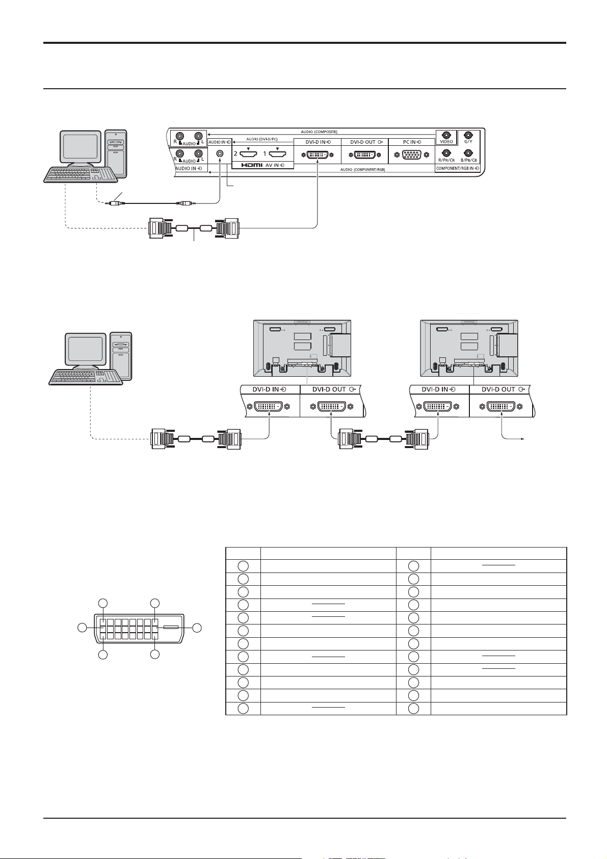
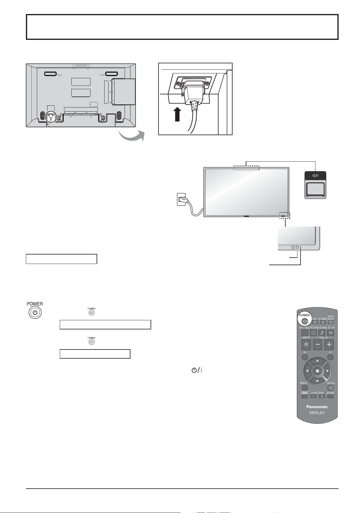
Connections
AC cord connection and ¿ xing
AC cord ¿ xing
Plug the AC cord into the display unit.
Plug the AC cord until it clicks.
Note:
Make sure that the AC cord is locked on
both the left and right sides.
Video equipment connection
AUDIO IN (COMPOSITE)
Connect the audio output of a device connected
to VIDEO.
(see page 9)
Unplug the AC cord
Unplug the AC cord pressing the
two knobs.
Note:
When disconnecting the AC cord, be
absolutely sure to disconnect the AC
cord plug at the socket outlet ¿ rst.
SERIAL IN, SERIAL OUT
SERIAL Input/Output
Terminal
Control the Display by
connecting to PC.
(see page 12)
AV IN
HDMI1, HDMI2
HDMI Input Terminal
(see page 9)
AUDIO IN
(COMPONENT / RGB)
Connect the audio output
of a device connected to
COMPONENT/RGB IN.
(see page 9)
DVI-D IN, DVI-D OUT
DVI-D Input/Output
Terminal
(see page 10)
PC IN
PC Input Terminal
(see page 11)
AUDIO IN (DVI-D / PC)
Connect the audio
output of a device
connected to DVI-D IN,
PC IN. (see page 10, 11)
VIDEO
Composite Video
Input Terminal
(see page 9)
COMPONENT/RGB IN
Component/RGB
Video Input Terminal
(see page 9)
8
Connections
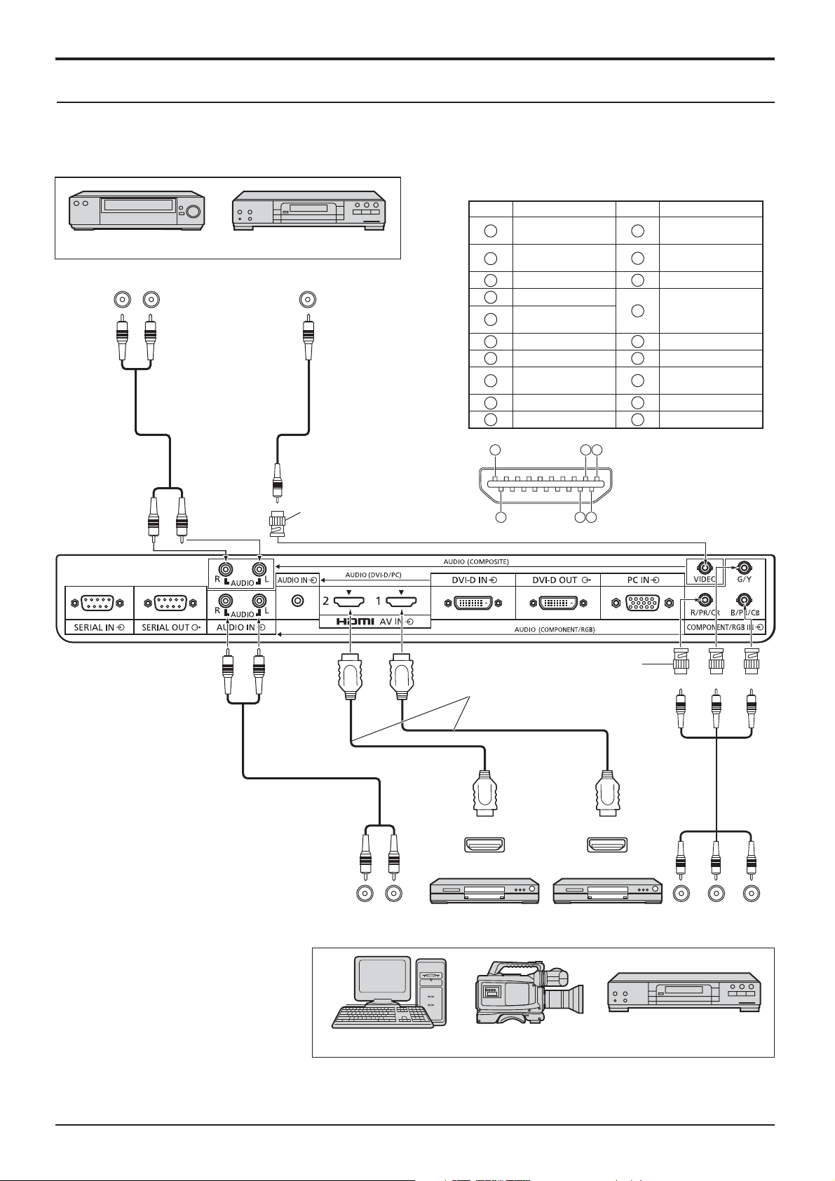
VIDEO, COMPONENT / RGB IN and HDMI connection
Note:
Additional equipment, cables and adapter plugs shown are not supplied with this set.
[Pin assignments and signal names for HDMI terminal]
VCR
AUDIO OUT
R
L
Pin No.
DVD Player
VIDEO OUT
Signal Name
1
T.M.D.S Data2+
T.M.D.S Data2
2
Shield
3
T.M.D.S Data2-
4
T.M.D.S Data1+
T.M.D.S Data1
5
Shield
6
T.M.D.S Data1-
7
T.M.D.S Data0+
T.M.D.S Data0
8
Shield
9
T.M.D.S Data0-
10
T.M.D.S Clock+
Pin No.
11
12
13
14
15
16
17
18
19
Signal Name
T.M.D.S Clock
Shield
T.M.D.S Clock-
CEC
Reserved
(N.C. on device)
SCL
SDA
DDC/CEC
Ground
+5V Power
Hot Plug Detect
Notes:
• Change the “Component/RGB-in
select” setting in the “Setup” menu
to “Component” (when Component
signal connection) or “RGB” (when
RGB signal connection). (see page
37)
• Accepts only RGB signals from
COMPONENT/RGB IN terminal
with “Sync on G”.
RCA-BNC
Adapter plug
AUDIO OUT RGB OUT
19
18
3 1
2
4
RCA-BNC
Adapter plug
HDMI cables
HDMI
AV O UT
HDMI
AV O UT
DVD playerDVD player
B PR OUT
RL
Y P
Computer RGB Camcorder
DVD Player
9
Connections
DVI-D IN, DVI-D OUT connection
PC with DVI-D
video out
Stereo mini plug (M3)
Shared with
PC IN.
DVI-video cable with Ferrite core (Within 5 m)
Daisy chain connection
When using the multi display, multiple LCD Displays can be daisy chained.
PC with DVI-D
First LCD Display Second LCD Display
video out
**
* DVI-video cable with Ferrite core
Third and
subsequent
LCD
Displays
Notes:
• Up to 10 displays can be connected with a daisy chain, but the number of the connected displays may be limited by
a cable, signal or equipment to use.
• HDCP can be supported for up to 8 displays for a daisy chain.
DVI-D Input/Output Connector
Pin Layouts
1
9
17
8
16
24
Connection port view
Pin No.
Signal Name
T.M.D.S. data 2-
1
T.M.D.S. data 2+
2
T.M.D.S. data 2 shield
3
4
5
DDC clock
6
DDC data
7
8
T.M.D.S. data 1-
9
T.M.D.S. data 1+
10
T.M.D.S. data 1 shield
11
12 24
Pin No.
13
14
15
16
17
18
19
20
21
22
23
Signal Name
+5 V DC
Ground
Hot plug detect
T.M.D.S. data 0T.M.D.S. data 0+
T.M.D.S. data 0 shield
T.M.D.S. clock shield
T.M.D.S. clock+
T.M.D.S. clock-
Notes:
• Additional equipment and cables shown are not supplied with this set.
• Use the DVI-D cable with Ferrite core complying with the DVI standard. Image deterioration may occur depending
on the length or the quality of the cable.
10
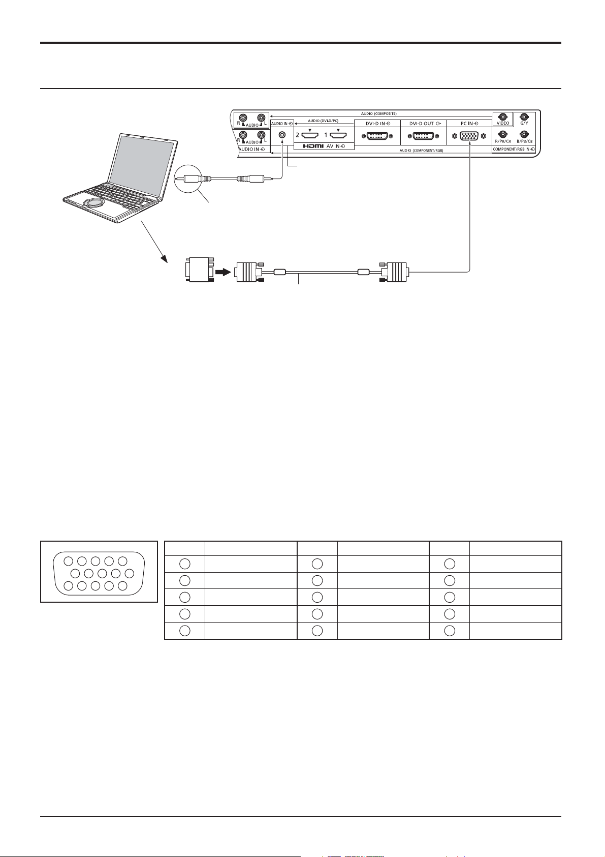
PC Input Terminals connection
COMPUTER
Shared with DVI-D IN.
Connections
(Female)
Audio
Connect a cable which matches
the audio output terminal on the computer.
Conversion adapter
(if necessary)
Stereo mini plug (M3)
RGB
PC cable with
Ferrite core
Mini D-sub 15p
(Male)
Notes:
• Computer signals which can be input are those with a horizontal scanning frequency of 30 to 110 kHz and vertical scanning
frequency of 48 to 120 Hz. (However, the image will not be displayed properly if the signals exceed 1,200 lines.)
• The display resolution is a maximum of 1,440 × 1,080 dots when the aspect mode is set to “4:3”, and 1,920 × 1,080
dots when the aspect mode is set to “16:9”. If the display resolution exceeds these maximums, it may not be possible
to show ¿ ne detail with suf¿ cient clarity.
• The PC input terminals are DDC2B-compatible. If the computer being connected is not DDC2B-compatible, you will
need to make setting changes to the computer at the time of connection.
• Some PC models cannot be connected to the set.
• There is no need to use an adapter for computers with DOS/V compatible Mini D-sub 15P terminal.
• The computer shown in the illustration is for example purposes only.
• Additional equipment and cables shown are not supplied with this set.
• Panasonic recommends using a PC cable that includes a Ferrite core.
• Do not set the horizontal and vertical scanning frequencies for PC signals which are above or below the speci¿ ed
frequency range.
Signal Names for Mini D-sub 15P Connector
Pin No. Signal Name Pin No. Signal Name Pin No. Signal Name
1
3 9 4 5
2
10
15 14 13 12 11
6 7 8
Pin Layout for PC Input
Terminal
1
2
3
4
NC (not connected)
5
GND (Ground)
R
G
B
6
7
8
9
10
GND (Ground)
GND (Ground)
GND (Ground)
+5 V DC
GND (Ground)
11
NC (not connected)
12
13
14
15
HD/SYNC
SDA
VD
SCL
11
Connections
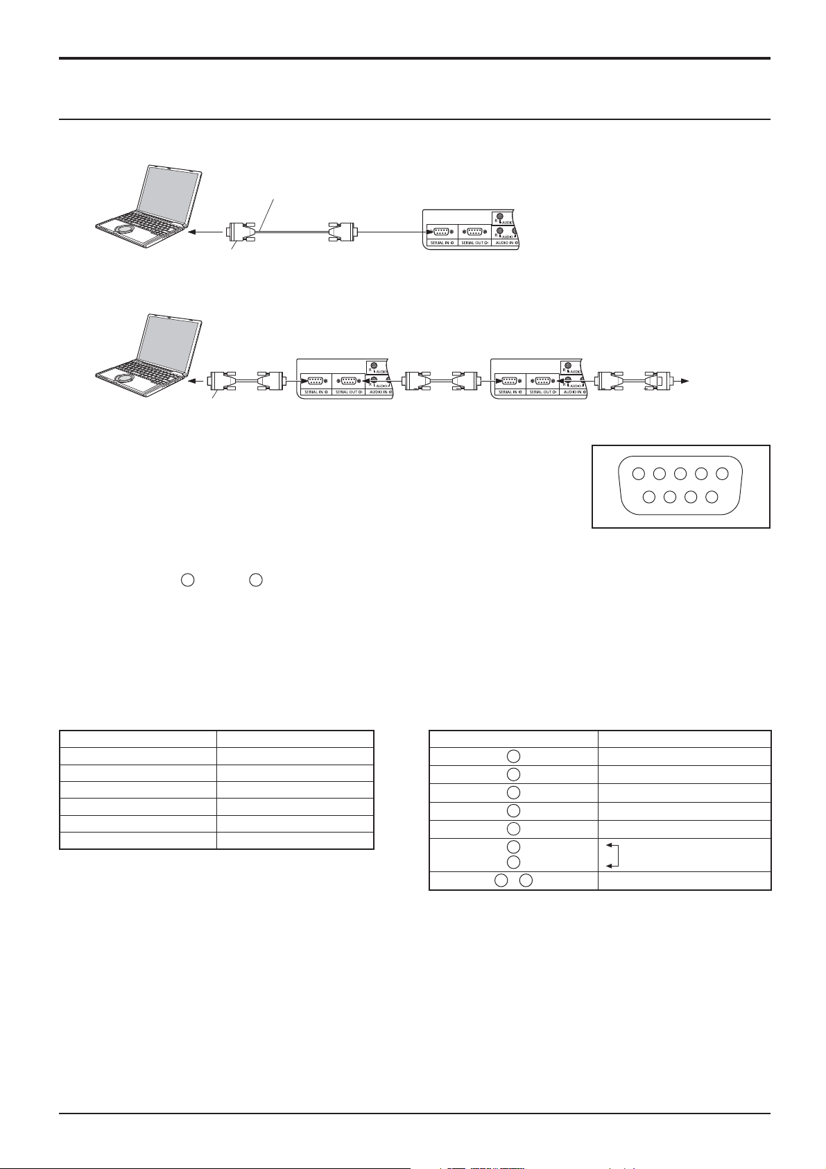
SERIAL Terminals connection
The SERIAL terminal is used when the Display is controlled by a computer.
COMPUTER
RS-232C Straight cable
(Female)
D-sub 9p
In addition, a particular LCD Display can be controlled with a PC while several LCD Displays are daisy chained.
(Male)
COMPUTER
D-sub 9p
(Female)
*
First LCD Display
(Male)
(Female)(Female)
*
* RS-232C Straight cable
Second LCD Display
(Male)
(Female) (Female)
*
Third LCD Display
(Male)
Notes:
• Use the RS-232C straight cable to connect the computer
to the Display.
• The computer shown is for example purposes only.
• Additional equipment and cables shown are not supplied
1 3 4 5 2
6 7 8 9
with this set.
• When using daisy chain, set ”Serial Daisy Chain” in the
Options menu. (see page 43)
Pin layout for SERIAL Terminal
• For daisy chain connection, use a straight cable connected
2
to pins numbered
through 8.
The SERIAL terminal conforms to the RS-232C interface speci¿ cation, so that the Display can be controlled by a
computer which is connected to this terminal.
The computer will require software which allows the sending and receiving of control data which satis¿ es the conditions
given below. Use a computer application such as programming language software. Refer to the documentation for
the computer application for details.
Communication parameters
Signal level RS-232C compliant
Synchronization method Asynchronous
Baud rate 9600 bps
Parity None
Character length 8 bits
Stop bit 1 bit
Flow control -
Signal names for SERIAL IN terminal
Pin No. Details
2
3
4
5
6
7
8
1
9
•
(Shorted in this set)
R X D
T X D
DTR
GND
DSR
NC
These signal names are those of computer speci¿ cations.
12
Connections
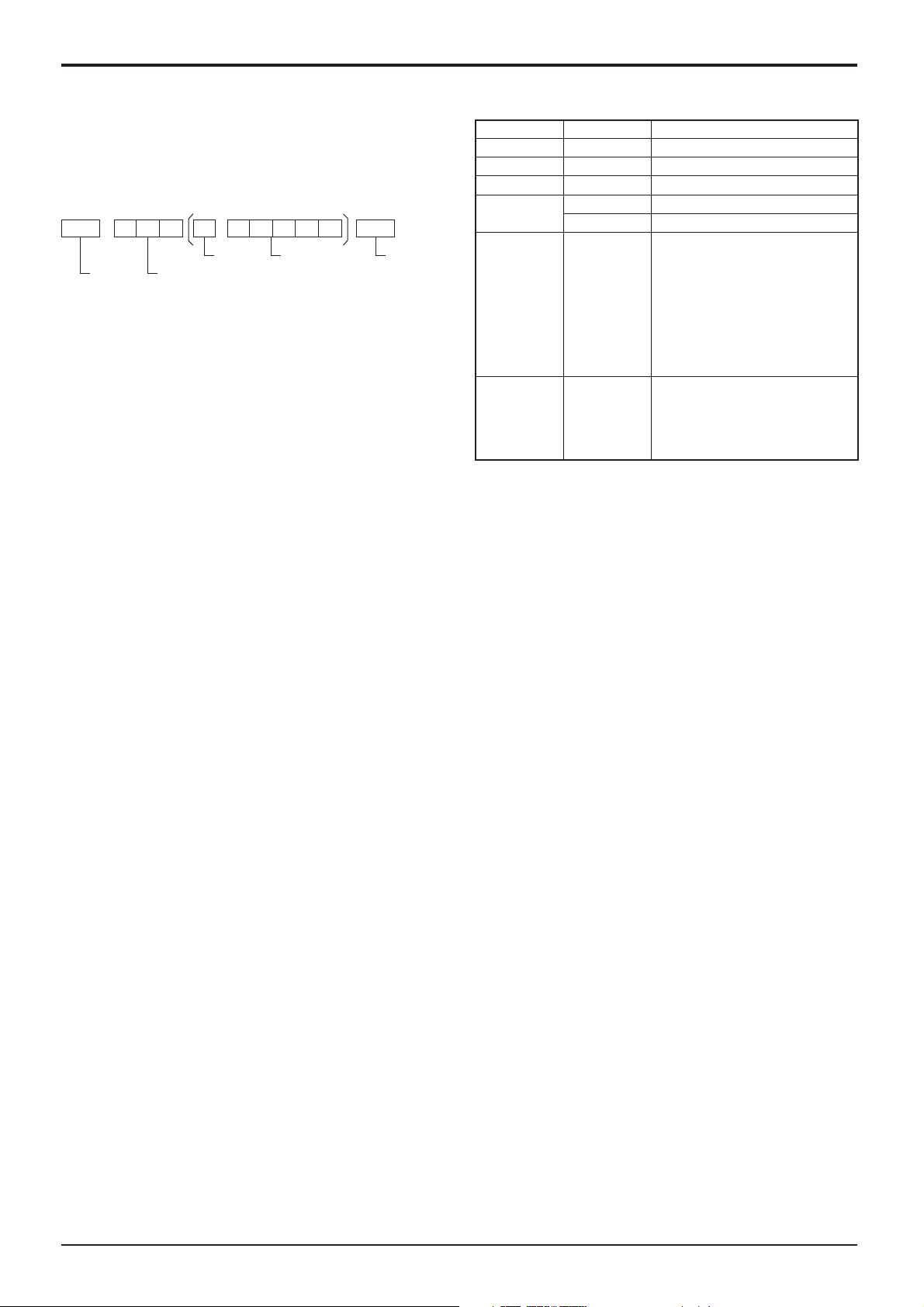
Basic format for control data
Command
The transmission of control data from the computer
starts with a STX signal, followed by the command, the
parameters, and lastly an ETX signal in that order. If there
are no parameters, then the parameter signal does not
need to be sent.
STX C1C2C3 P1P2P3P4:P5ETX
Start
(02h)
Colon Parameter(s)
3-character
command (3 bytes)
(1 - 5 bytes)
End
(03h)
Notes:
• If multiple commands are transmitted, be sure to wait for
the response for the ¿ rst command to come from this unit
before sending the next command.
• If an incorrect command is sent by mistake, this unit will
send an “ER401” command back to the computer.
• Consult an Authorized Service Center for detail instructions
on command usage.
With the power off, this display responds to PON command
only.
Command Parameter Control details
PON None Power ON
POF None Power OFF
AVL *** Volume 000 - 100
AMT
IMS None
DAM None
0 Audio MUTE OFF
1 Audio MUTE ON
Input select (toggle)
SL1
AV1
AV2
HM1
HM2
DV1
PC1
ZOOM
FULL
NORM
ZOM2
SLOT input (SLOT INPUT)
VIDEO input (VIDEO)
COMPONENT/RGB IN input
(Component)
HDMI1 input (HDMI1)
HDMI2 input (HDMI2)
DVI-D IN input (DVI)
PC IN input (PC)
Screen mode select (toggle)
Zoom1
16:9
4:3
Zoom2
13
Power On / Off
Connecting the AC cord plug to the Display.
Connecting the plug to the Wall Outlet
Notes:
• Main plug types vary between countries. The power
plug shown at right may, therefore, not be the type
¿ tted to your set.
• When disconnecting the AC cord, be absolutely
sure to disconnect the AC cord plug at the socket
outlet ¿ rst.
Power switch
Press the Power switch on the Display to turn the
set on: Power-On.
Power Indicator: Green
Press the button on the remote control to turn the Display off.
Power Indicator: Red (standby)
Press the
Power Indicator: Green
Turn the power to the Display off by pressing the
the Display is on or in standby mode.
Note:
During operation of the power management function, the power indicator turns
orange in the power off state.
button on the remote control to turn the Display on.
Remote Control Sensor
Power Indicator
switch on the unit, when
14
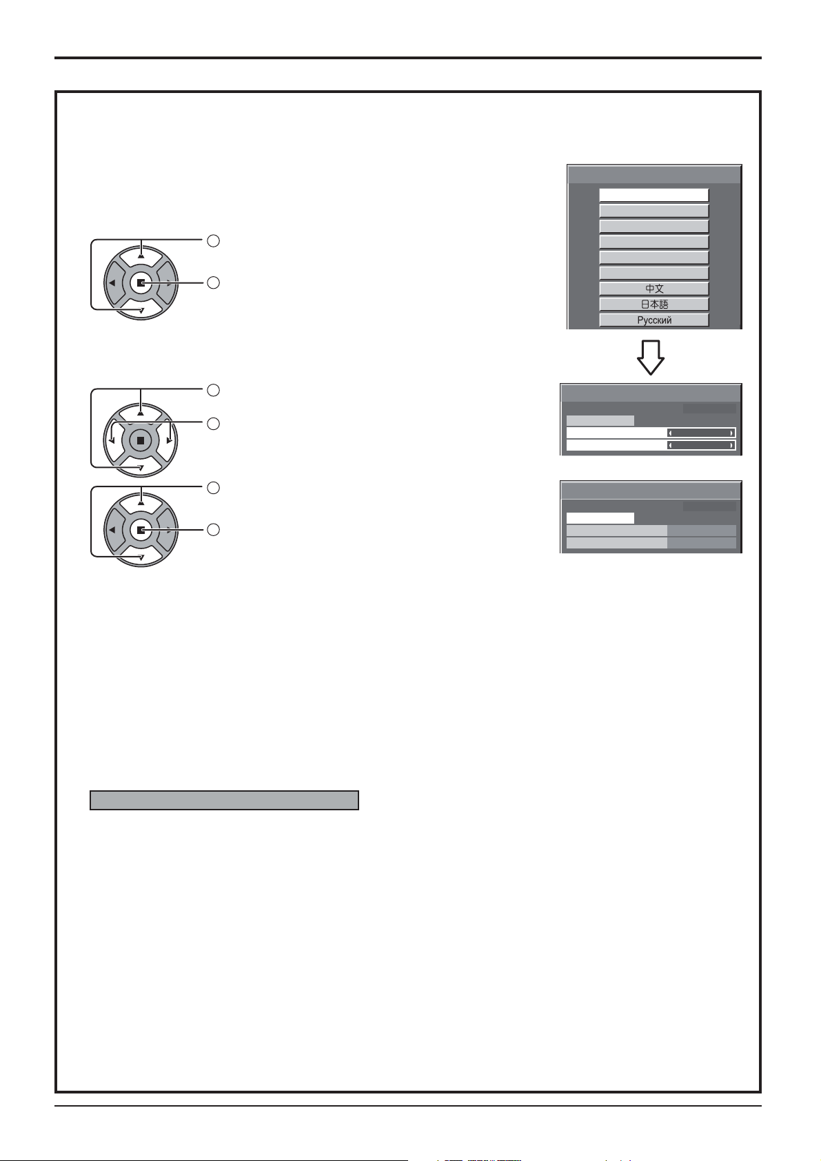
When ¿ rst switching on the unit
Following screen will be displayed when the unit is turned on for the ¿ rst time.
Select the items with the remote control. Unit buttons are invalid.
OSD Language
1
Select the language.
2
Set.
PRESENT TIME Setup
1
Select “DAY” or “PRESENT TIME”.
2
Setup “DAY” or “PRESENT TIME”.
Power On / Off
OSD Language
English (UK)
Deutsch
Français
Italiano
Español
ENGLISH (US)
PRESENT TIME Setup
PRESENT TIME MON 99 : 99
Set
DAY
PRESENT TIME
MON
99 : 99
1
Select “Set”.
2
Set.
PRESENT TIME Setup
PRESENT TIME MON 99 : 99
Set
DAY
PRESENT TIME
TUE
10 : 00
Notes:
• Once the items are set, the screens won't be displayed when switching on the unit next time.
• After the setting, the items can be changed in the following menus.
OSD Language (see page 34)
PRESENT TIME Setup (see page 27)
Power ON warning message
The following message may be displayed when turning the unit power ON:
No activity power off Precautions
’No activity power off’ is enabled.
If “No activity power off” in Setup menu is set to “Enable”, a warning message is displayed every time
the power is turned ON. (see page 31)
This message display can be set with the following menu: Options menu
Power On Message (see page 44)
15
 Loading...