

Panasonic TH-42PX80U, TH-50PX80U, TH-42PZ80U, TH-46PZ80U, TH-50PZ80U Service Manual
...
11
th
Generation Full High Definition Plasma Display TV
This Seminar covers the following models: TH-42PX80U, TH-50PX80U, TH-42PZ80U, TH-46PZ80U
TH-50PZ80U, TH-42PZ85U, TH-46PZ85U, and TH50PZ85U
Panasonic Technology and Service Company
National Training

This page is purposely left blank.
2
2
Panasonic ideas for life
Prepared by
Cesar Perdomo
Panasonic Service and Technology Company
National Training
Copyright © 2008 by Panasonic Service and Technology Company
All rights reserved. Unauthorized copying and distribution is a violation of law.
!
Warning
This service information is designed for experienced repair technicians only and is not designed for use by the
general public. It does not contain warnings or cautions to advise non-technical individuals of potential dangers
in attempting to service a product. Products powered by electricity should be serviced or repaired only by
experienced professional technicians. Any attempt to service or repair the product or products dealt with in this
service information by anyone else could result in serious injury or death.
3
3
Panasonic ideas for life
Table Of Contents
Subject Page
Topics 5
Models Line-up (46” PDP TV Introduction for 2008) 6
Models Comparison 7
TH-XXPX80U
TH-42PX80U Comparison to Last Year’s Models 8
Connectors Location (TH-42PX80U) 9
Power Supply/Signal Process/Panel Drive Circuit 10 -11
Power Supply (Standby) TH-42PX80U-TH50PX80U 12
Standby Operation 13
Connectors Location on the P board (TH-42PX80U) 14
Power On Operation TH-42PX80U-TH50PX80U 15
Power On Circuit Explanation 16
Voltages Distribution (TH-42PX80U) 17-18
TH-XXPZ80U and TH-XXPZ85U
Boards Name and Function (TH-XXPZ80U/PZ85U) 20
Board Layout
TH-42PZ85U 22-23
TH-42PZ85U Connectors Location 24
TH-42PZ85U D Board and C Boards Location 25
Start-up Process 26-27
Start-up Process Block Diagram 28
Start up Process Description 29
Start up Process Description 30
Start-up Process Explanation 31
Sub-Voltages Distribution Block Diagram 32
Sub-Voltages Distribution Explanation 33
Troubleshooting 10 blinks Condition At Plug in (Schematic) 34
Troubleshooting 10 blinks Condition At Plug in 35
Power On Operation Block Diagram 37
The Power On Circuit Explanation 38
Voltages Distribution 39
Troubleshooting 10 blinks Condition Power On (Schematic) 40
Troubleshooting 10 blinks Condition Power On 41
Circuit Operation When A6 and A7 are Removed 43
Circuit Operation When A6 and A7 are Removed 44
Picture of connector A6 and A7 location 45
Power LED Blinking timing chart 47
D board SOS Detect 48
21
D board SOS Detect (Explanation) 49-51
2 Blinks Error Code Block Diagram 52
Troubleshooting 2 Blinks Error Code 53
5 Blinks Error Code Block Diagram 54
Troubleshooting 5 Blinks Error Code 55
D16280(D280) Location (8 Blinks) 56
8 Blinks SOS Detect Circuit 57
Sustain Drive Board (SS) Isolation 58
Sustain Drive (SS) Board Isolation (Explanation) 59
SC/SU/SD Board Isolation (Explanation) 60
DRV Reset (6 Blinks) 61
Drive Reset Circuit Explanation 62
SU/SD Board Isolation (Pictorial) 63
SC/SU/SD Board Isolation (Explanation) 64
SC/SU/SD Board Isolation (Block Diagram) 65
Symptoms caused by defective SD boards 66
Symptom Caused By Defective SU Board 67
A board SOS Detect Block Diagram 68
A board SOS Detect (Explanation) 69
Digital Signal Processor Block Diagram (TH-42PZ85U) 71
Digital Signal Processor Explanation (TH-42PZ85U) 72
Switching to 4:3 to confirm problem with the A board 73
D Board (Format Converter/Plasma AI Processor) 74
Circuit Explanation 75-76
Pictures Of symptoms caused by the D board 77
Service Mode 79
Internal Test Patterns 80
Self Check 81
Check Point 82
Self Check Menu 83
How To Reset 84
Data Copy To SD Card 86-87
Data Copy From SD Card to The TV 88
How to Copy Self Check Data To SD Card 89-90
Software Upgrade 91-94
Picture Refresh 95-96
Extension Cable List 97-98
Extension Cable TH-XXPX80U (A Board) (P Board) 99-102
Subject Page
4
4
Panasonic ideas for life

Topics
Models Line-up (46” PDP TV Introduction for 2008)
HD Models/Full HD Models
Standby Operation
Power-on Operation
Shutdown Detect Circuit
Troubleshooting
Signal Process Circuit
Panel Drive Circuit
Adjustments
Service Notes
5
5
Panasonic ideas for life
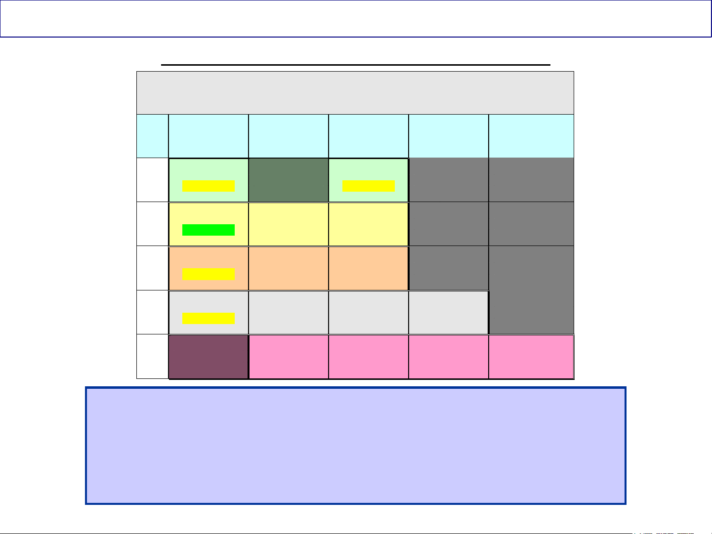
Models Line-up (46” PDP TV Introduction for 2008)
Panasonic has introduced a 46” PDP TV for 2008
2008 Panasonic PDP TV Series (11th Generation)
42” 46” 50” 58” 65”
HD
FHD
FHD
FHD
FHD TH-46PZ850U TH-50PZ850U TH-58PZ850U TH-65PZ850U
TH-42PX80U
(1 P Board)
TH-42PZ80U
(1 P Board)
TH-42PZ85U
(1 P Board)
TH-42PZ800U
(1 P Board)
TH-46PZ80U
(2 P Boards)
TH-46PZ85U
(2 P Boards)
TH-46PZ800U
(2 P Boards)
TH-50PX80U
(1 P Board)
TH-50PZ80U
(2 P Boards)
TH-50PZ85U
(2 P Boards)
TH-50PZ800U
(2 P Boards)
TH-58PZ800U
(2 P Boards)
All the new 42” PDP TVs only have 1 “Power Supply” (P) board.
The 46”, 50”, and 58” models, with the exception of TH-50PX80U,
have 2 “Power Supply” (P) boards.
These boards have different part numbers
6
Panasonic ideas for life
6
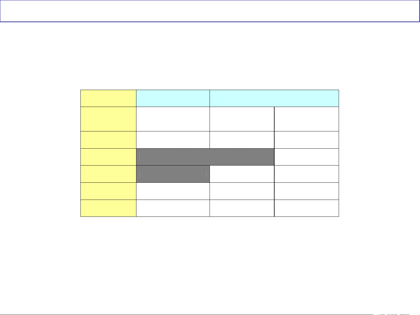
2008 Models Comparison
HD FULL HD
Model
Resolution
PC Input 1
D Board Yes Yes
A Board Yes Yes Yes
Contrast Ratio 15,000:1 20,000:1 30,000:1
TH-42PX80U
TH-50PX80U
1,024 by 768 (42”)
1,366 by 768 (50”)
TH-42PZ80U
TH-46PZ80U
TH-50PZ80U
1,920 by 1,080 1,920 by 1,080
TH-42PZ85U
TH-46PZ85U
TH-50PZ85U
Panel Life Expectancy = 100,000 Hrs
Altitude/Elevation Rating = 2800 Meter (9240 feet)
7
7
Panasonic ideas for life
TH-42PX80U Comparison to Last Year’s Models
The Models TH-42PX80U and
TH-50PX80U do not have a D
board. The circuits normally found
in the D board on previous
models, are now built into the A
board.
No D
Board
D Board
TH-42PX75U (2007 Model)
TH-42PX80U (2008 Model)
8
8
Panasonic ideas for life
Connectors Location (TH-42PX80U)
This slide shows the location of the connectors on all the boards
9
Panasonic ideas for life
9
Power Supply/Signal Process/Panel Drive Circuit
TH-42PX80U
10
10
Panasonic ideas for life

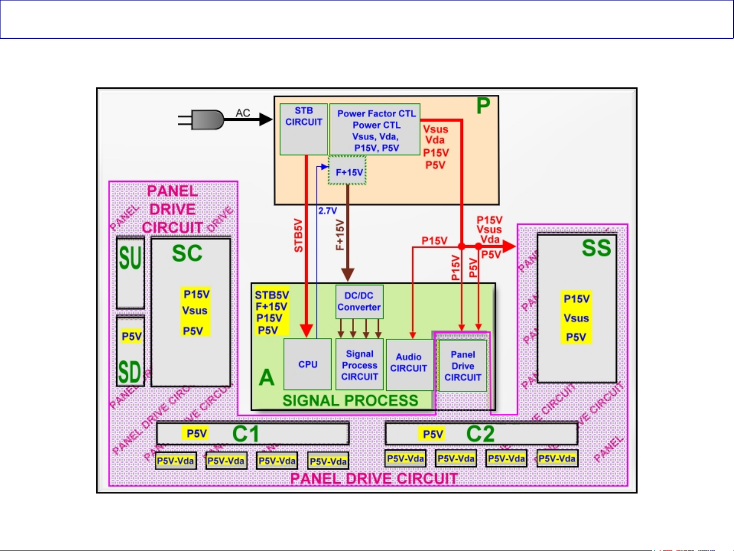
Power Supply/Signal Process/Panel Drive Circuit
The PDP TV consists of several circuits.
The Power Supply:
This circuit provides the voltages necessary to drive all the circuits in the
TV.
Signal Processing/CPU:
This circuit is designed to perform all the functions necessary to process
any input signal.
The CPU provides commands to turn on the TV. It communicates with
other components on the TV via the bus line. It also provides protection by
monitoring the supply voltages for abnormalities.
Panel Drive Circuit:
This circuit provides the control drive pulses to the drive circuit boards to
drive the panel.
11
Panasonic ideas for life
11
Power Supply (Standby) TH-42PX80U-TH50PX80U
12
12
Panasonic ideas for life

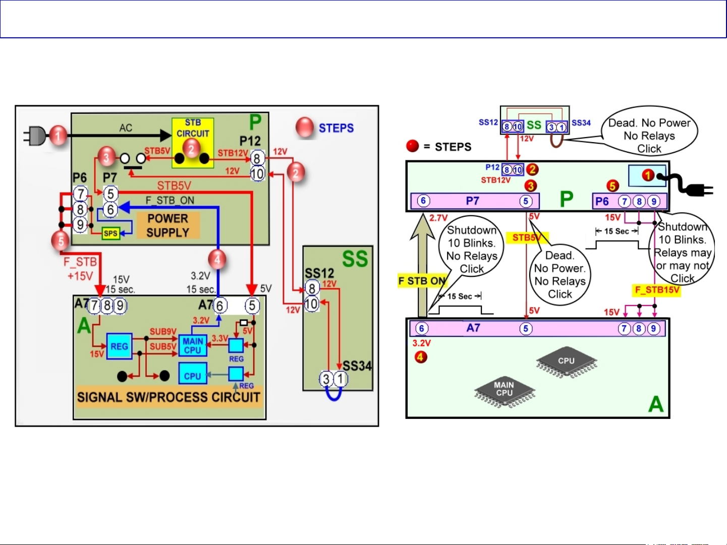
Standby Operation
When the TV is plugged in:
AC is applied to the standby circuit in the power supply to produce STB12V and STB5V.
The STB12V is routed thru the SS board and it’s returned back to the P board to turn on a
switching circuit that outputs the STB5V. If the STB5V is missing, the TV is dead (No power)
The STB5V is output from the P board at pin 5 of connector P7 and it is applied to pin 5 of
connector A7 on the A board.
The STB5V is applied to a 3.3V regulator to power the Main CPU (IC1100) on the A board.
When the Main CPU (IC1100) receives 3.3V, it outputs a temporary 2.7V/3.2V command that
is provided to pin 6 of connector P7 on the P board. The function of this command is to turn on
the circuit that generates the “F+15V” in the P board.
The P board outputs the F+15V to pins 7, 8, and 9 of connector A7 in the A board. This voltage
is applied to a regulator circuit that generates: SUB9V, SUB5V, and SUB3.V.
If any of these voltages (F+15V, SUB9V, SUB5V, and SUB3.3V) are missing, the TV shuts
down and the power LED blinks 10 times.
13
Panasonic ideas for life
13
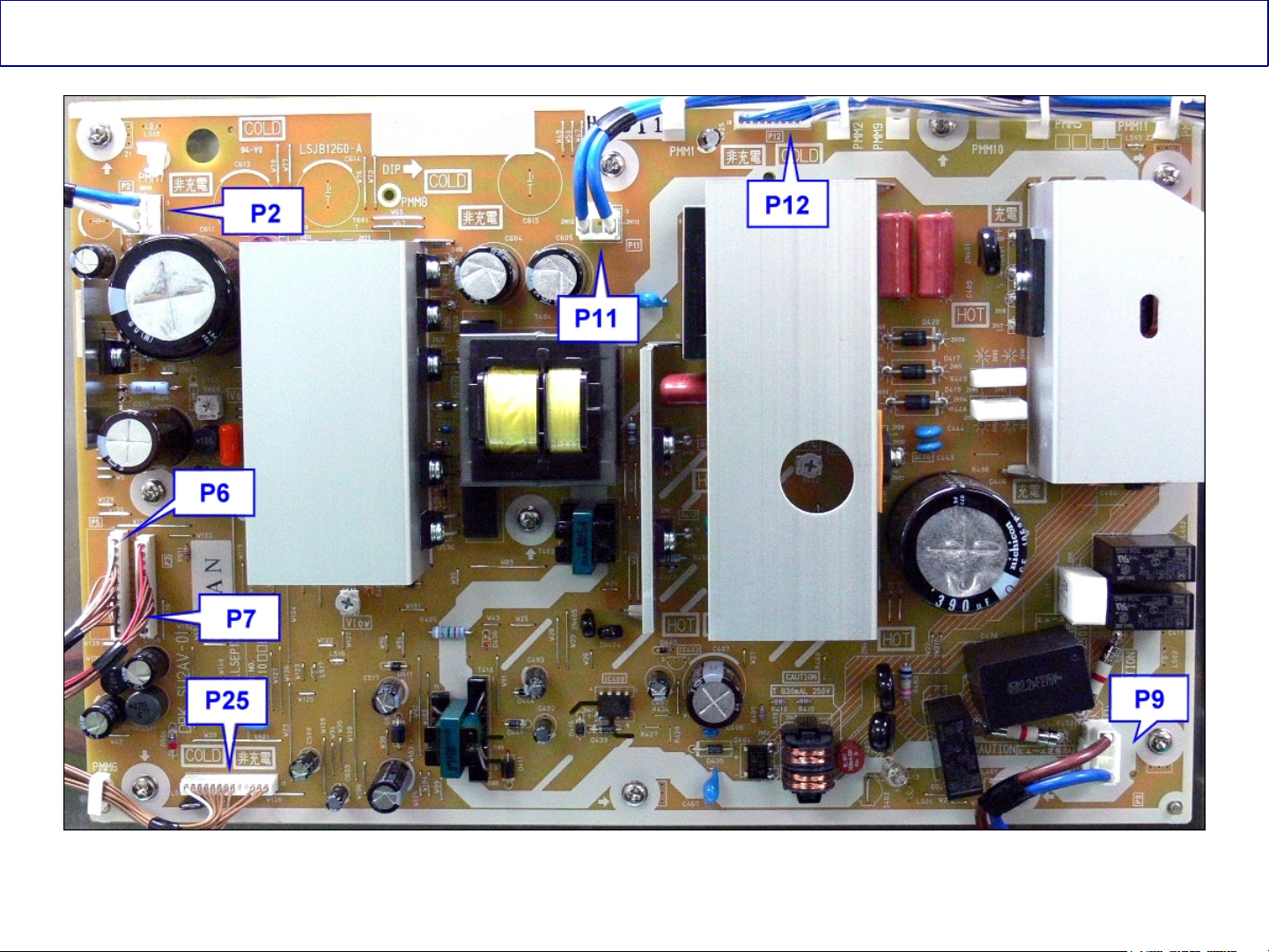
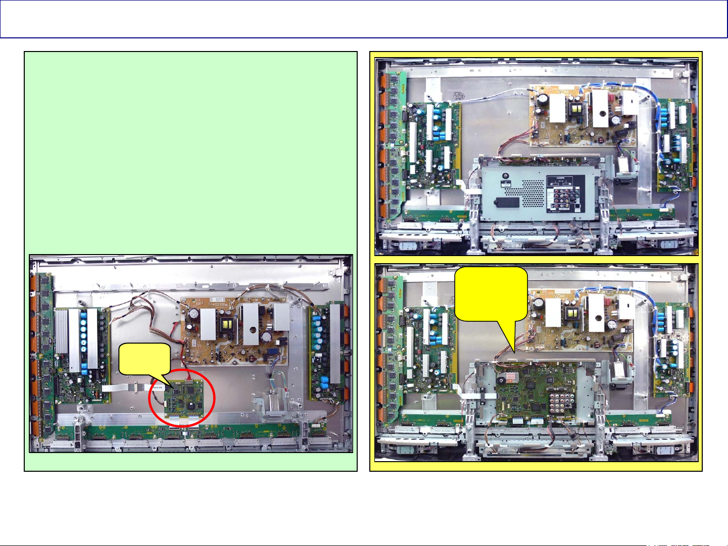
Connectors Location on the P board (TH-42PX80U)
This picture shows the location of the connectors on the P board
14
Panasonic ideas for life
14
Power On Operation TH-42PX80U-TH50PX80U
15
15
Panasonic ideas for life

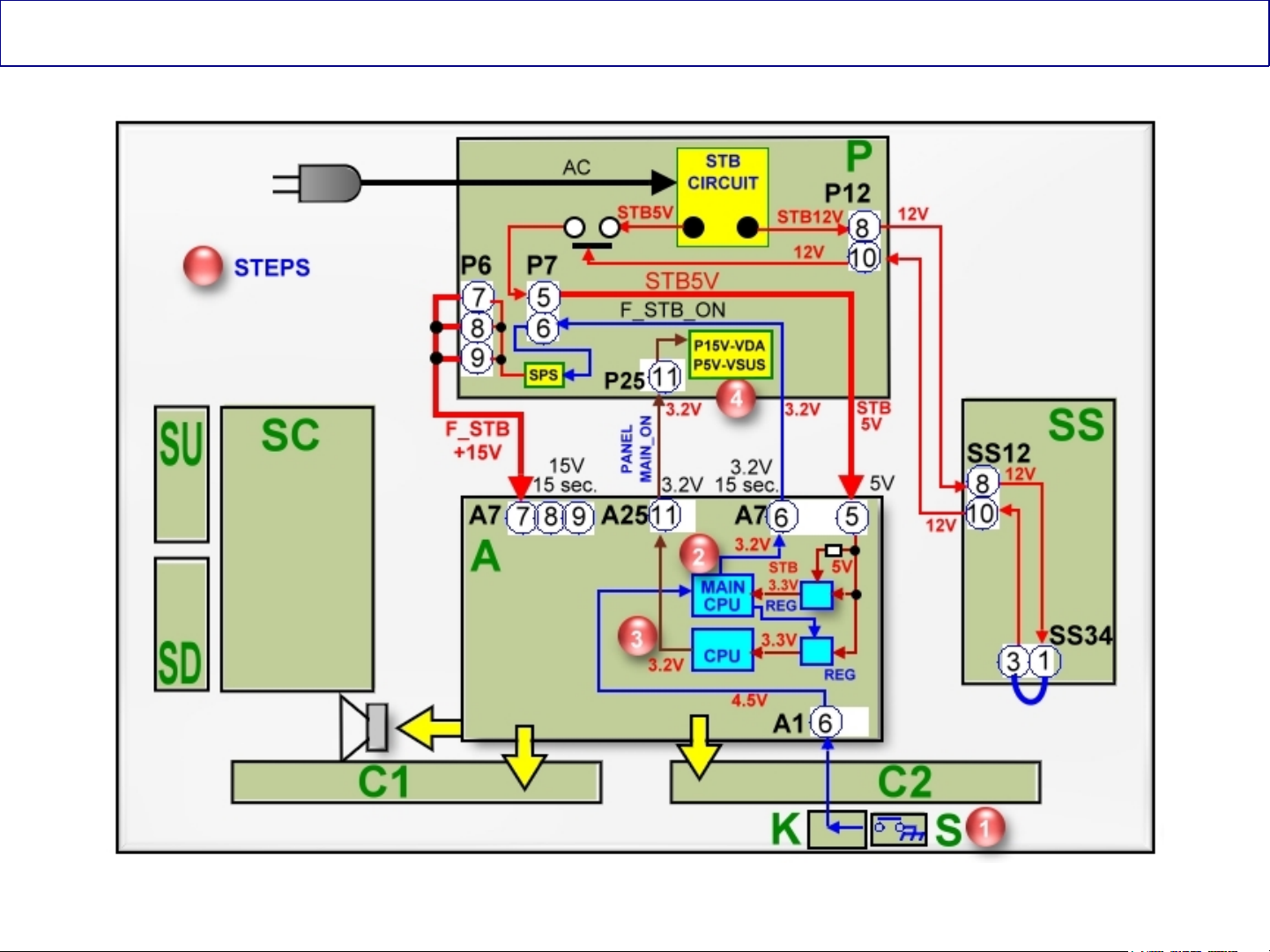
Power On Circuit Explanation
1. The power command from the power switch on the S board or the remote control receiver on the K
board is provided to the Main CPU on the A board thru connector A1. The CPU on the A board outputs
the “F_STB_ON” Command and the PANEL_STB_ON” command.
2. The “F_STB_ON” command is provided to pin 6 of connector P7 of the power supply to develop the
F_STB+15V.
3. The “PANEL_STB_ON” is used to turn on the STB3.3V regulator on the A board. The output voltage is
applied to the “Panel” CPU on the A board (Formerly located in the D board).
4. When the “Panel” CPU on the A board is energized, it outputs the “PANEL_MAIN_ON” Command
(3.2V) to pin 11 of connector P25 on the P board.
The PANEL MAIN ON command turns on the power supply circuit that outputs the Vsus, Vda, 15V, and
5V.
16
16
Panasonic ideas for life
Voltages Distribution (TH-42PX80U)
17
17
Panasonic ideas for life
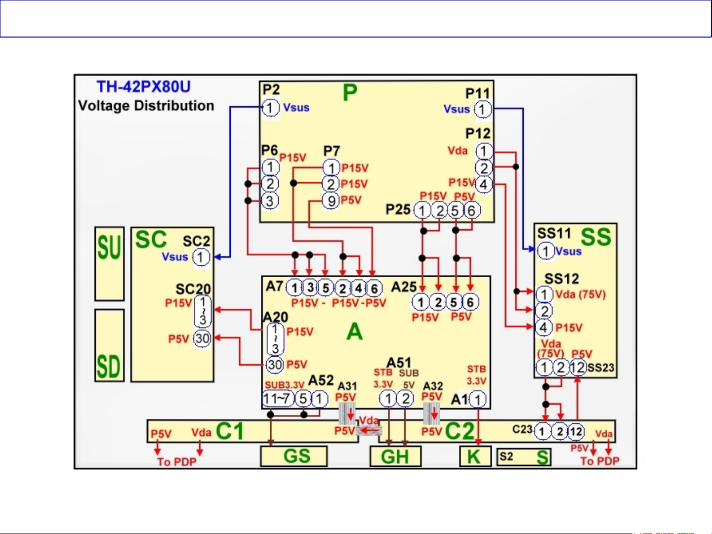
Voltages Distribution (TH-42PX80U)
18
18
Panasonic ideas for life

Because of the similarities between the TH-XXPX80U, the TH-XXPZ80U,
and TH-XXPZ85U, from this point forward, the material used in the guide
is based on the TH-XXPZ85U.
TH-XXPZ80U and TH-XXPZ85U
19
19
Panasonic ideas for life
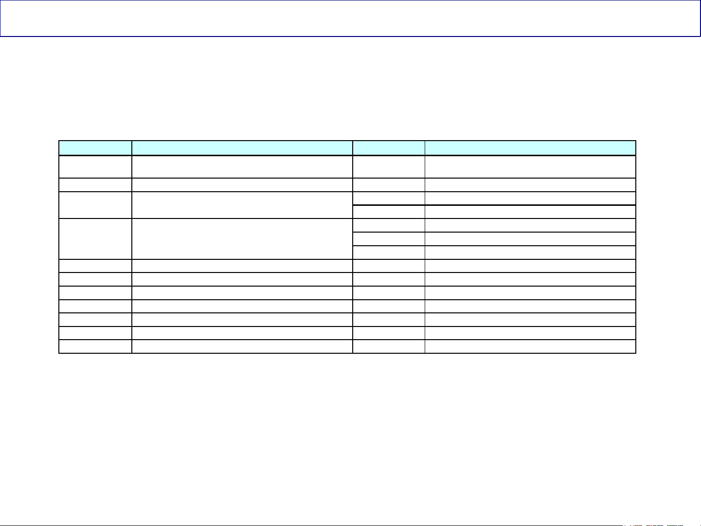
Boards Name and Function (TH-XXPZ80U/PZ85U)
Board Name Function Board Name Function
P Power Supply D
PB Fan control C1 Data Driver (Upper Right)
A Speaker out, Sound Processor AV Terminal,
AV Switch
DC-DC Converter Digital Signal Processor,
Microcomputer HDMI Interface, Peaks Lite 2,
Full HD
SC Scan Drive
G Front terminal, AV3, Key Switch SU Scan out (Upper)
K Remote receiver, Power LED SD Scan out (Lower)
S Pow er Switch SS Sustain Drive
GS SD Card Slot
GH HDMI3 in
C2 Data Driver (Upper Left)
Format Converter, Plasma AI, Sub-Field
Processor
20
20
Panasonic ideas for life

Board Layout
Panasonic has been using single scan addressing in our standard definition (SD)
Plasma TVs for a while now.
In 2006 (9
42” HD models.
In 2007 (10
single scan addressing.
For 2008 (11
Full HD models (PZ80, PZ85, and PZ800 (Not yet confirmed in PZ850) were
also added to the list.
th
generation), Panasonic started using single scan addressing in our
th
generation), the 50” HD models were added to the list of TV using
th
generation), the 42” and 50” (Not yet confirmed in 58” and 65”)
21
21
Panasonic ideas for life
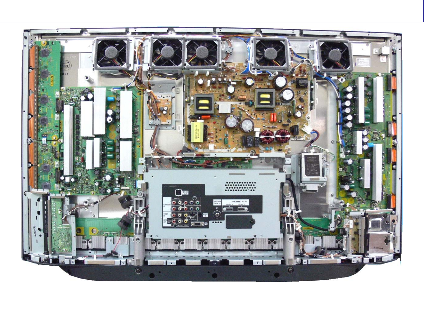
TH-42PZ85U
This is a picture of the TV with the rear cover removed
22
Panasonic ideas for life
22
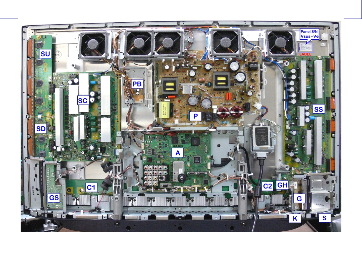
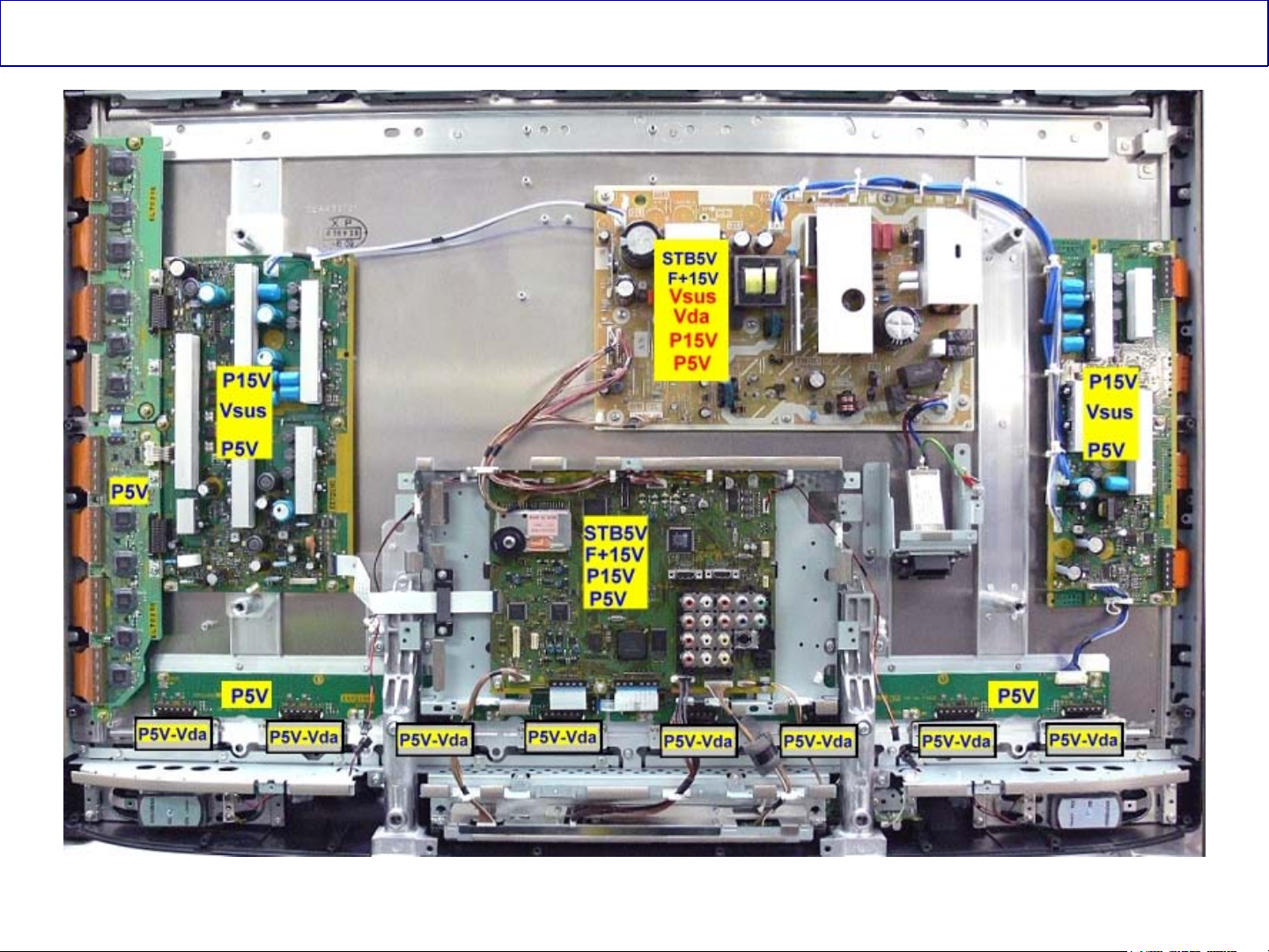
TH-42PZ85U Pictorial Boards Layout
In this line of Full HD Plasma TVs, the number of boards used have been reduced.
Both the DG board and the H board are no longer used. The circuits found in these boards are now part
of the A board.
23
Panasonic ideas for life
23
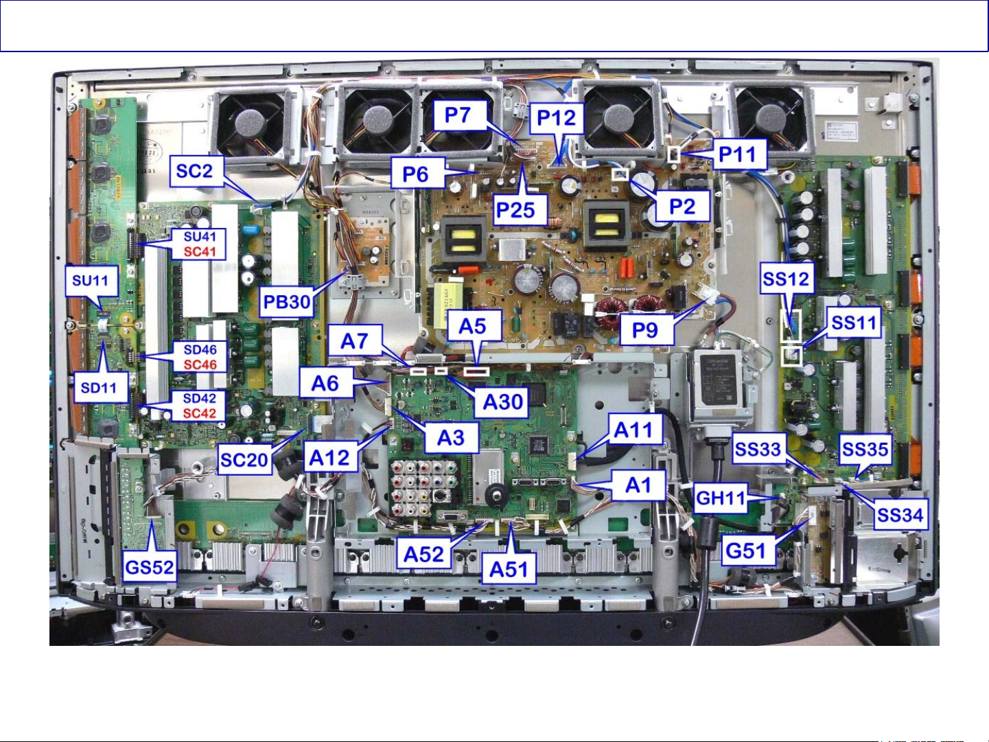
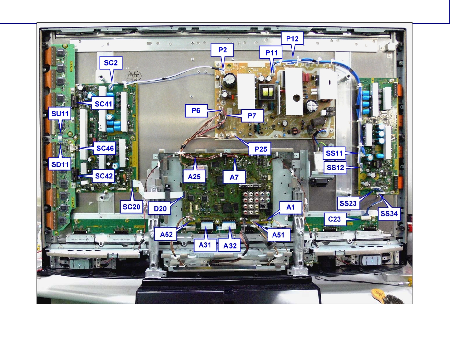
TH-42PZ85U Connectors Location
This picture shows the location of all the connectors in the TV.
24
Panasonic ideas for life
24
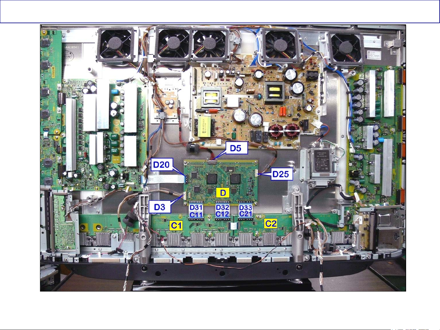
TH-42PZ85U D Board and C Boards Location
This picture shows the location of the D board and its connectors.
25
Panasonic ideas for life
25

Start-up Process
26
26
Panasonic ideas for life

Start-up Process
Upon connecting the Panasonic Plasma Display Television to the AC line, the sound of
relays being triggered can be heard from the Power Supply board. Also a red light from
the Optical jack on the back of the TV can be observed.
Approximately 15 seconds later, the click sound from the relays can be heard again and
the red LED inside the Optical jack turns off.
This condition is normal and by paying attention to this sequence of events, we can
confirm the operation of several circuits inside the TV.
27
27
Panasonic ideas for life
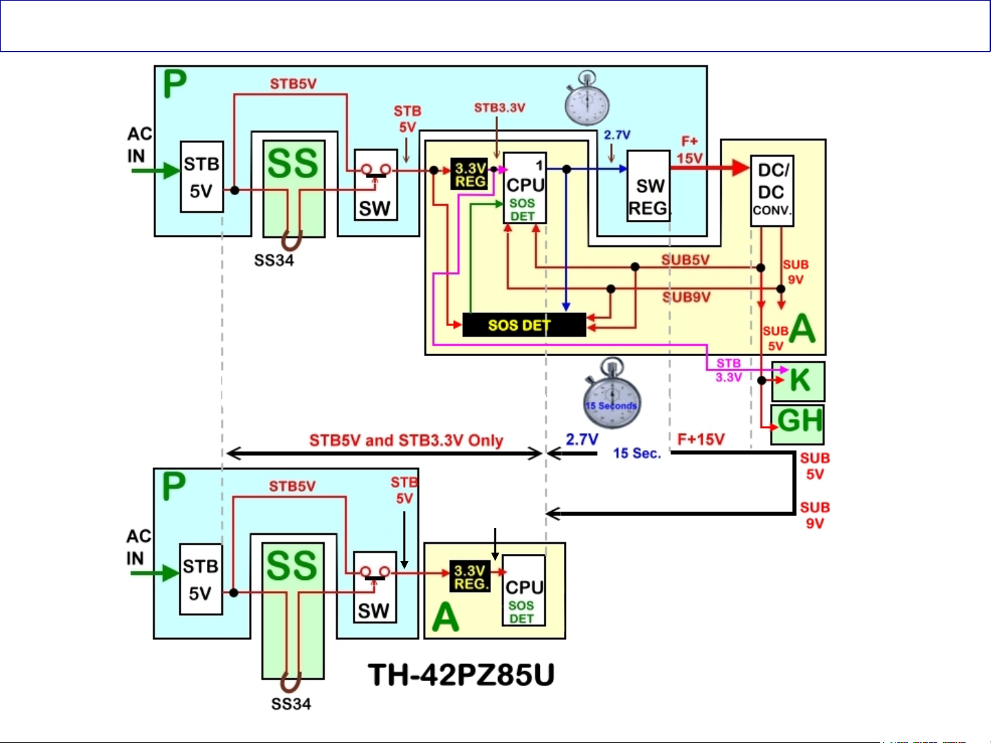
Start-up Process Block Diagram
STB
3.3V
28
28
Panasonic ideas for life

Start up Process Description
When the TV is plugged in:
AC is applied to the power supply board (P) through connector P9. The AC
is applied to the standby circuit to produce STB12V and STB5V.
The STB5V is routed thru the SS board to turn on a circuit which function is to allow the
output of the STB5V through connector P7.
The STB5V is output from the P board at pin 5 of connector P7 and it is applied to pin 5 of
connector A7 on the A board.
The STB5V is applied to a 3.3V regulator to power the Main CPU (IC1100) on the A board.
The 3.3V becomes STB3.3V.
The STB3.3V is applied to the power LED and the remote control receiver in the K board.
When the Main CPU (IC1100) receives 3.3V, it outputs a 2.7V command that is provided to the
P board and the SOS Detect circuit within the A board. This command only lasts approximately
15 seconds and it is called “F-STB-ON”. The function of this command is to turn on the circuit
that generates the “F-STB-14V” in the P board.
The function of the 2.7V command applied to the SOS Detect circuit in the A board together
with the STB5V, is to activate the “SOS DETECT” circuit in the A board.
The F+15V from connector P6 on the P board is applied to connector A6 in the A board. This
voltage is applied to a regulator circuit that generates: SUB9V, SUB5V, and SUB3.V.
29
Panasonic ideas for life
29
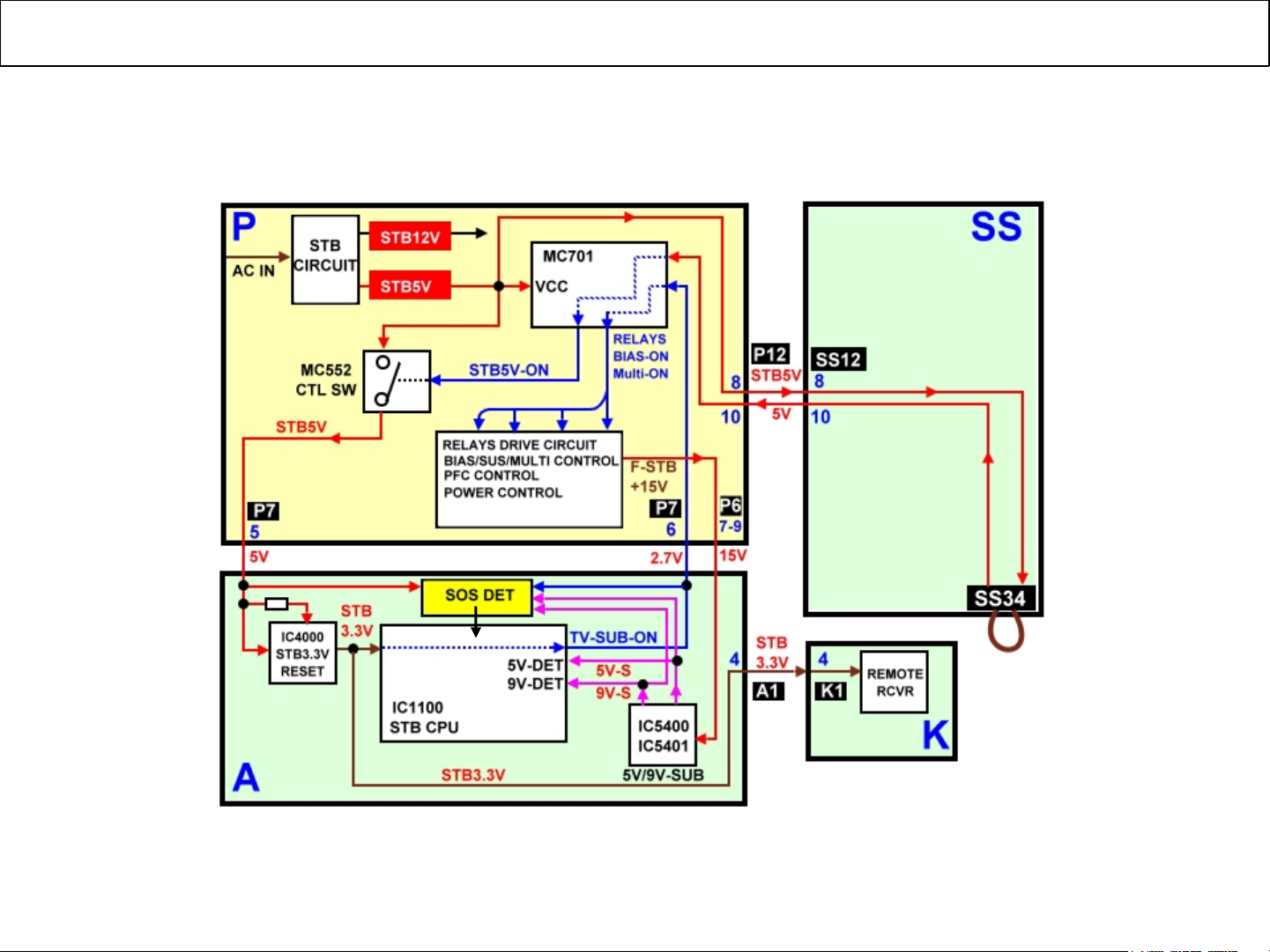
Start-up Process (Detailed Circuit)
This is a detailed block diagram of the start up process
30
30
Panasonic ideas for life
 Loading...