

Page 1
ORDER NO. PAVCI17060012
Model No. TH-43E460D
Chassis: KM34
Destination: INDIA
LED TV
TABLE OF CONTENTS
1 Safety Precautions ----------------------------------------------- 3
1.1. General Guidelines---------------------------------------- 3
1.1.1. Leakage Current Cold Check ---------------------- 3
1.1.2.
Leakage Current Hot Check (See Figure 1.)
2 Warning-------------------------------------------------------------- 4
2.1. Prevention of Electrostatic Discharge (ESD)
to Electrostatically Sensitive (ES) Devices---------- 4
2.2. About lead free solder (PbF)---------------------------- 5
3 Service Navigation ----------------------------------------------- 6
3.1. Service Hint ------------------------------------------------- 6
4 Specifications ----------------------------------------------------- 7
5 Service Mode ------------------------------------------------------ 9
5.1. How to enter into Service Mode ----------------------- 9
5.1.1. Purpose ------------------------------------------------- 9
5.1.2. Key command ----------------------------------------- 9
5.1.3. How to exit---------------------------------------------- 9
5.1.4. Contents of adjustment mode --------------------- 9
5.1.5. Display of SOS History -----------------------------10
5.1.6. Exit-------------------------------------------------------10
5.1.7. Hotel Mode --------------------------------------------10
PAG E PAG E
6 Troubleshooting Guide --------------------------------------- 11
6.1. Check of the IIC bus lines------------------------------ 11
6.1.1. How to access --------------------------------------- 11
---- 3
6.1.2. Self-check indication only ------------------------- 11
6.1.3. Self-check indication and forced to factory
shipment setting ------------------------------------- 11
6.1.4. Exit ------------------------------------------------------ 11
6.1.5. Screen display --------------------------------------- 11
6.2. Power LED Blinking timing chart --------------------- 12
6.3. Method of detecting SOS ------------------------------ 12
6.4. LCD Panel test mode ----------------------------------- 13
6.5. No Power--------------------------------------------------- 13
7 Disassembly and Assembly Instructions--------------- 14
7.1. Screw Installation(Panel)------------------------------- 14
7.2. Keybutton & LED Panel Ass’y ------------------------ 15
7.3. Side AV Bracket Ass’y ---------------------------------- 16
7.4. Felt Sticking------------------------------------------------ 17
7.5. Vesa Metal & Bottom Bakcover----------------------- 18
7.6. Sub Woofer Ass'y----------------------------------------- 19
7.7. Backcover--------------------------------------------------- 20
© Panasonic Corporation 2017.
Page 2

TH-43E460D
7.8. Label Installation------------------------------------------ 21
7.9. Pedestal Assembly -------------------------------------- 22
7.10.Accessories Ass’y----------------------------------------- 23
8 Measurements and Adjustments -------------------------- 24
8.1. Voltage chart of A-board-------------------------------- 24
8.2. Voltage chart of P-board-------------------------------- 24
9 Block Diagram --------------------------------------------------- 25
9.1. Main Block Diagram -------------------------------------25
10 Wiring Connection Diagram ---------------------------------26
10.1. Wire Dressing ---------------------------------------------26
11 Schematic Diagram---------------------------------------------27
12 Printed Circuit Board ------------------------------------------ 44
13 Exploded View and Replacement Parts List -----------49
2
Page 3
TH-43E460D
1 Safety Precautions
1.1. General Guidelines
1. When servicing, observe the original lead dress. If a short circuit is found, replace all parts which have been overheated or
damaged by the short circuit.
2. After servicing, see to it that all the protective devices such as insulation barriers, insulation papers shields are properly
installed.
3. After servicing, make the following leakage current checks to prevent the customer from being exposed to shock hazards.
4. When conducting repairs and servicing, do not attempt to modify the equipment, its parts or its materials.
5. When wiring units (with cables, flexible cables or lead wires) are supplied as repair parts and only one wire or some of the
wires have been broken or disconnected, do not attempt to repair or re-wire the units. Replace the entire wiring unit instead.
6. When conducting repairs and servicing, do not twist the Faston connectors but plug them straight in or unplug them straight
out.
1.1.1. Leakage Current Cold Check
1. Unplug the AC cord and connect a jumper between the
two prongs on the plug.
2. Measure the resistance value, with an ohmmeter,
between the jumpered AC plug and each exposed
metallic cabinet part on the equipment such as
screwheads, connectors, control shafts, etc. When the
exposed metallic part has a return path to the chassis, the
reading should be 8.5Mohm to 13Mohm.
When the exposed metal does not have a return path to
the chassis, the reading must be .
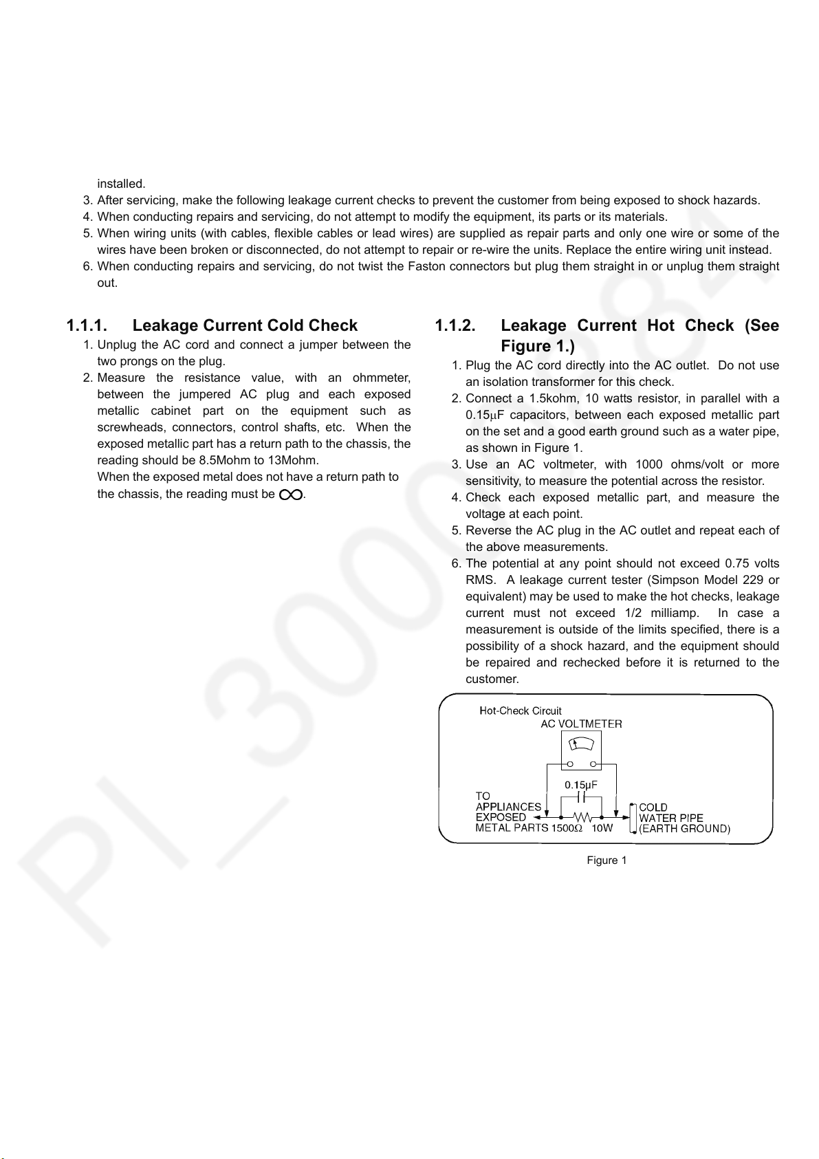
1.1.2. Leakage Current Hot Check (See
Figure 1.)
1. Plug the AC cord directly into the AC outlet. Do not use
an isolation transformer for this check.
2. Connect a 1.5kohm, 10 watts resistor, in parallel with a
0.15F capacitors, between each exposed metallic part
on the set and a good earth ground such as a water pipe,
as shown in Figure 1.
3. Use an AC voltmeter, with 1000 ohms/volt or more
sensitivity, to measure the potential across the resistor.
4. Check each exposed metallic part, and measure the
voltage at each point.
5. Reverse the AC plug in the AC outlet and repeat each of
the above measurements.
6. The potential at any point should not exceed 0.75 volts
RMS. A leakage current tester (Simpson Model 229 or
equivalent) may be used to make the hot checks, leakage
current must not exceed 1/2 milliamp. In case a
measurement is outside of the limits specified, there is a
possibility of a shock hazard, and the equipment should
be repaired and rechecked before it is returned to the
customer.
Figure 1
3
Page 4
TH-43E460D
2Warning
2.1. Prevention of Electrostatic Discharge (ESD) to Electrostatically
Sensitive (ES) Devices
Some semiconductor (solid state) devices can be damaged easily by static electricity. Such components commonly are called
Electrostatically Sensitive (ES) Devices. Examples of typical ES devices are integrated circuits and some field-effect transistors and
semiconductor [chip] components. The following techniques should be used to help reduce the incidence of component damage
caused by electrostatic discharge (ESD).
1. Immediately before handling any semiconductor component or semiconductor-equipped assembly, drain off any ESD on your
body by touching a known earth ground. Alternatively, obtain and wear a commercially available discharging ESD wrist strap,
which should be removed for potential shock reasons prior to applying power to the unit under test.
2. After removing an electrical assembly equipped with ES devices, place the assembly on a conductive surface such as
aluminum foil, to prevent electrostatic charge buildup or exposure of the assembly.
3. Use only a grounded-tip soldering iron to solder or unsolder ES devices.
4. Use only an anti-static solder removal device. Some solder removal devices not classified as [anti-static (ESD protected)] can
generate electrical charge sufficient to damage ES devices.
5. Do not use freon-propelled chemicals. These can generate electrical charges sufficient to damage ES devices.
6. Do not remove a replacement ES device from its protective package until immediately before you are ready to install it. (Most
replacement ES devices are packaged with leads electrically shorted together by conductive foam, aluminum foil or
comparable conductive material).
7. Immediately before removing the protective material from the leads of a replacement ES device, touch the protective material
to the chassis or circuit assembly into which the device will be installed.
Caution
Be sure no power is applied to the chassis or circuit, and observe all other safety precautions.
8. Minimize bodily motions when handling unpackaged replacement ES devices. (Otherwise ham less motion such as the
brushing together of your clothes fabric or the lifting of your foot from a carpeted floor can generate static electricity (ESD)
sufficient to damage an ES device).
4
Page 5
TH-43E460D
2.2. About lead free solder (PbF)
Note: Lead is listed as (Pb) in the periodic table of elements.
In the information below, Pb will refer to Lead solder, and PbF will refer to Lead Free Solder.
The Lead Free Solder used in our manufacturing process and discussed below is (Sn+Ag+Cu).
That is Tin (Sn), Silver (Ag) and Copper (Cu) although other types are available.
This model uses Pb Free solder in it’s manufacture due to environmental conservation issues. For service and repair work, we’d
suggest the use of Pb free solder as well, although Pb solder may be used.
PCBs manufactured using lead free solder will have the PbF within a leaf Symbol PbF stamped on the back of PCB.
Caution
• Pb free solder has a higher melting point than standard solder. Typically the melting point is 50 ~ 70 °F (30~40 °C) higher. Please
use a high temperature soldering iron and set it to 700 ± 20 °F (370 ± 10 °C).
• Pb free solder will tend to splash when heated too high (about 1100 °F or 600 °C).
If you must use Pb solder, please completely remove all of the Pb free solder on the pins or solder area before applying Pb
solder. If this is not practical, be sure to heat the Pb free solder until it melts, before applying Pb solder.
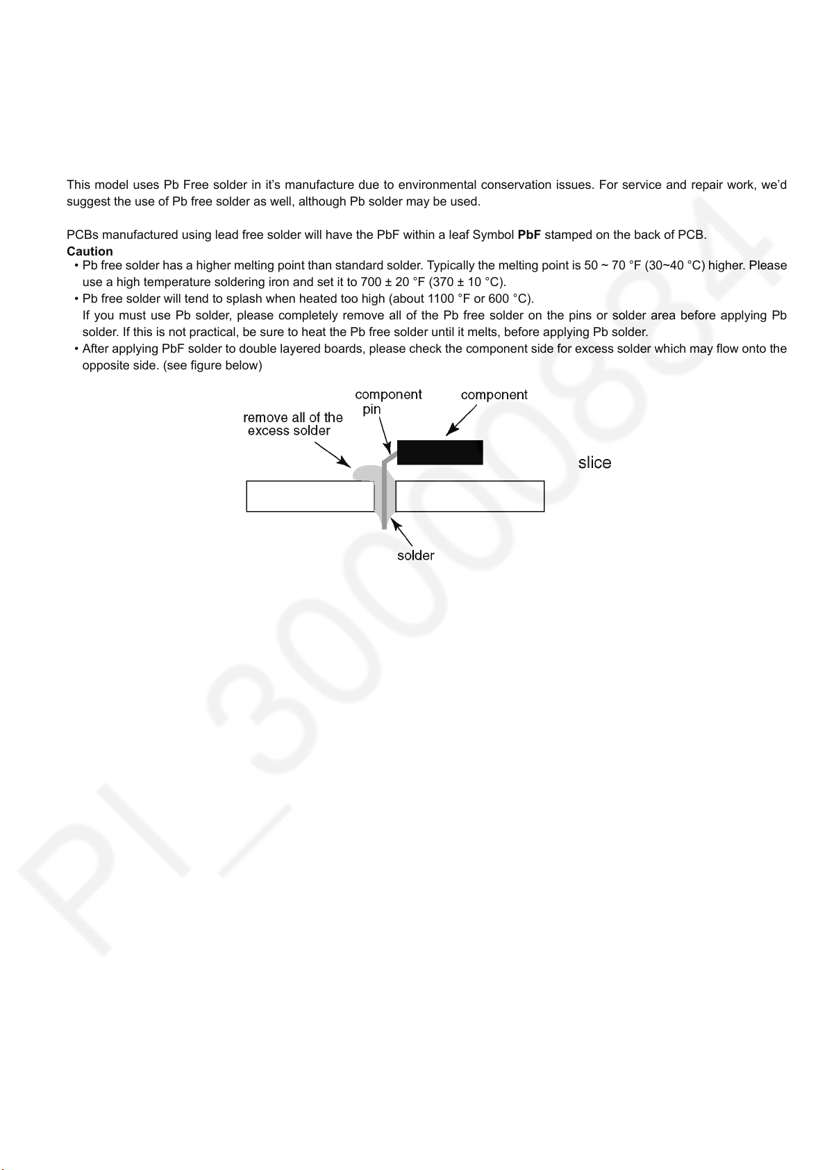
• After applying PbF solder to double layered boards, please check the component side for excess solder which may flow onto the
opposite side. (see figure below)
5
Page 6
TH-43E460D
3 Service Navigation
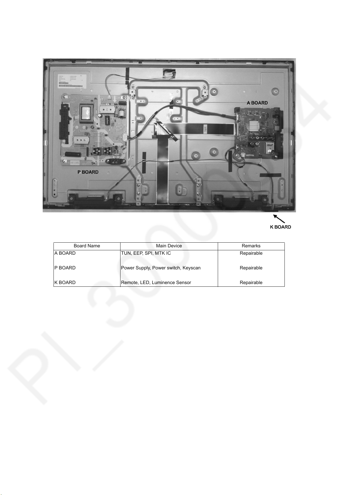
3.1. Service Hint
Board Name Main Device Remarks
A BOARD TUN, EEP, SPI, MTK IC Repairable
P BOARD Power Supply, Power switch, Keyscan Repairable
K BOARD Remote, LED, Luminence Sensor Repairable
6
Page 7
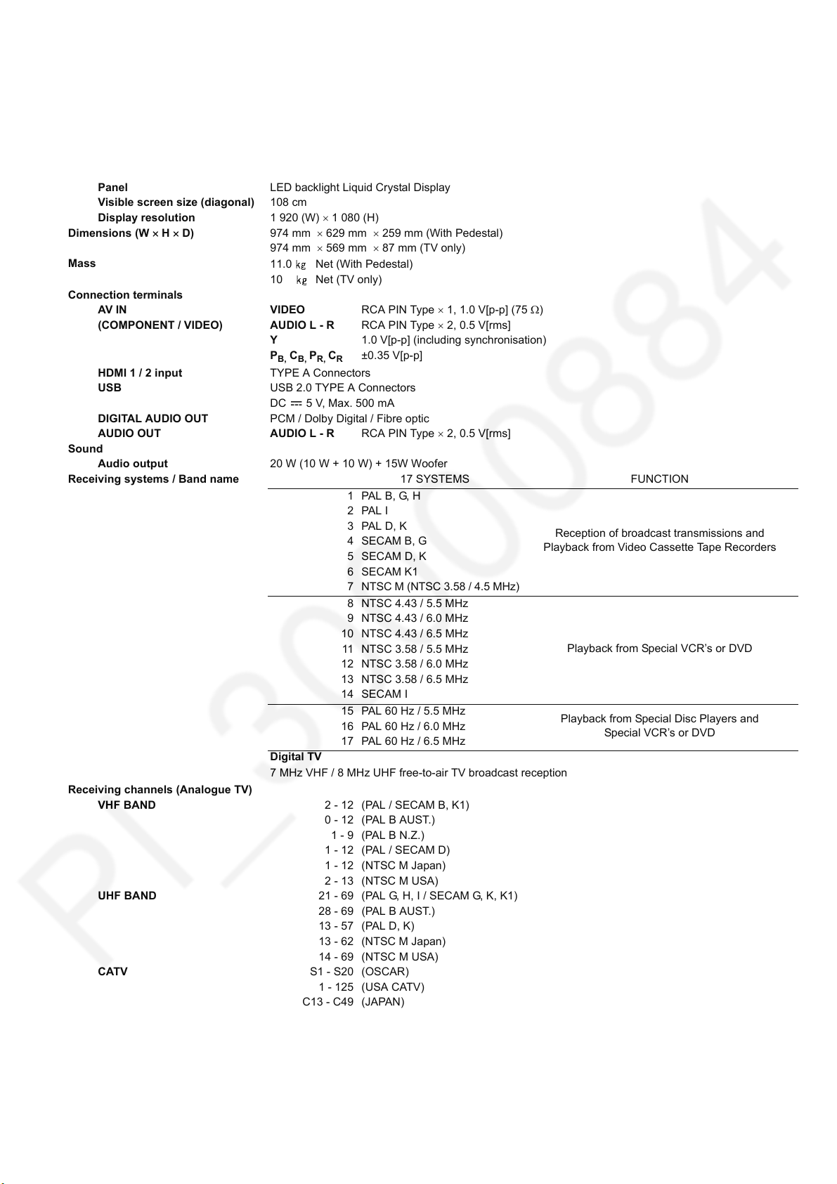
4 Specifications
Power source AC 110-240 V, 50 / 60 Hz
Power consumption
(Rated power / Standby power)
Display panel
Panel LED backlight Liquid Crystal Display
Visible screen size (diagonal) 108 cm
Display resolution 1 920 (W) 1 080 (H)
Dimensions (W H D) 974 mm 629 mm 259 mm (With Pedestal)
Mass
Connection terminals
AV I N V ID EO RCA PIN Type 1, 1.0 V[p-p] (75 )
(COMPONENT / VIDEO) AUDIO L - R RCA PIN Type 2, 0.5 V[rms]
HDMI 1 / 2 input TYPE A Connectors
USB USB 2.0 TYPE A Connectors
DIGITAL AUDIO OUT PCM / Dolby Digital / Fibre optic
AUDIO OUT AUDIO L - R RCA PIN Type 2, 0.5 V[rms]
Sound
Audio output 20 W (10 W + 10 W) + 15W Woofer
Receiving systems / Band name 17 SYSTEMS FUNCTION
Receiving channels (Analogue TV)
VHF BAND 2 - 12 (PAL / SECAM B, K1)
UHF BAND 21 - 69 (PAL G, H, I / SECAM G, K, K1)
CATV S1 - S20 (OSCAR)
89 W / 0.20 W
974 mm 569 mm 87 mm (TV only)
11.0 Net (With Pedestal)
10 Net (TV only)
Y 1.0 V[p-p] (including synchronisation)
P
B, CB, PR, CR
DC 5 V, Max. 500 mA
Digital TV
7 MHz VHF / 8 MHz UHF free-to-air TV broadcast reception
28 - 69 (PAL B AUST.)
13 - 57 (PAL D, K)
13 - 62 (NTSC M Japan)
14 - 69 (NTSC M USA)
1 - 125 (USA CATV)
C13 - C49 (JAPAN)
S21 - S41 (HYPER)
Z1 - Z37 (CHINA)
±0.35 V[p-p]
1 PAL B, G, H
2PAL I
3PAL D, K
4 SECAM B, G
5SECAM D, K
6 SECAM K1
7
NTSC M (NTSC 3.58 / 4.5 MHz)
8 NTSC 4.43 / 5.5 MHz
9 NTSC 4.43 / 6.0 MHz
10 NTSC 4.43 / 6.5 MHz
11 NTSC 3.58 / 5.5 MHz
12 NTSC 3.58 / 6.0 MHz
13 NTSC 3.58 / 6.5 MHz
14 SECAM I
15 PAL 60 Hz / 5.5 MHz
16 PAL 60 Hz / 6.0 MHz
17 PAL 60 Hz / 6.5 MHz
0 - 12 (PAL B AUST.)
1 - 9 (PAL B N.Z.)
1 - 12 (PAL / SECAM D)
1 - 12 (NTSC M Japan)
2 - 13 (NTSC M USA)
5A, 9A (AUST.)
Reception of broadcast transmissions and
Playback from Video Cassette Tape Recorders
Playback from Special VCR’s or DVD
Playback from Special Disc Players and
Special VCR’s or DVD
TH-43E460D
7
Page 8

TH-43E460D
Aerial input VHF / UHF
Operating Conditions Temperature : 0°C - 40°C
Humidity : 20% - 80% RH (non-condensing)
Note
• Design and Specifications are subject to change without notice. Mass and Dimensions shown are approximate.
8
Page 9
TH-43E460D
5 Service Mode
5.1. How to enter into Service Mode
5.1.1. Purpose
After exchange parts, check and adjust the contents of adjustment mode.
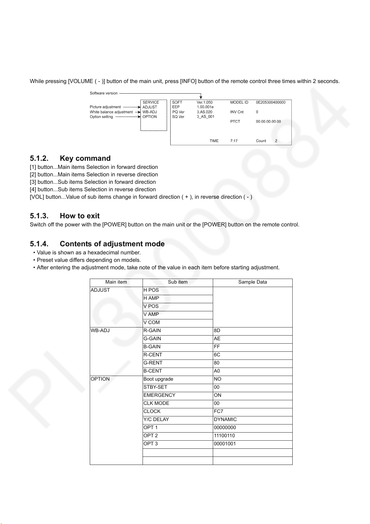
While pressing [VOLUME ( - )] button of the main unit, press [INFO] button of the remote control three times within 2 seconds.
5.1.2. Key command
[1] button...Main items Selection in forward direction
[2] button...Main items Selection in reverse direction
[3] button...Sub items Selection in forward direction
[4] button...Sub items Selection in reverse direction
[VOL] button...Value of sub items change in forward direction ( + ), in reverse direction ( - )
5.1.3. How to exit
Switch off the power with the [POWER] button on the main unit or the [POWER] button on the remote control.
5.1.4. Contents of adjustment mode
• Value is shown as a hexadecimal number.
• Preset value differs depending on models.
• After entering the adjustment mode, take note of the value in each item before starting adjustment.
Main item Sub item Sample Data
ADJUST H POS
H AMP
V POS
V AMP
V COM
WB-ADJ R-GAIN 8D
G-GAIN AE
B-GAIN FF
R-CENT 6C
G-RENT 80
B-CENT A0
OPTION Boot upgrade NO
STBY-SET 00
EMERGENCY ON
CLK MODE 00
CLOCK FC7
Y/C DELAY DYNAMIC
OPT 1 00000000
OPT 2 11100110
OPT 3 00001001
OPT 4 00000000
EDID-CLK HIGH
9
Page 10
TH-43E460D
5.1.5. Display of SOS History
SOS History (Number of LED blinking) indication.
From left side; Last SOS, before Last, three occurrence before, 2nd occurrence after shipment, 1st occurrence after shipment.
This indication except 2nd and 1st occurrence after shipment will be cleared by [Self-check indication and forced to factory
shipment setting].
5.1.6. Exit
1. Disconnect the AC cord from wall outlet.
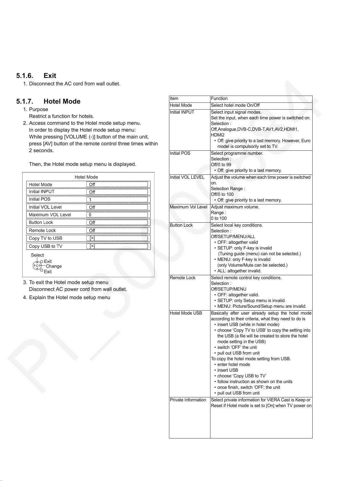
5.1.7. Hotel Mode
1. Purpose
Restrict a function for hotels.
2. Access command to the Hotel mode setup menu.
In order to display the Hotel mode setup menu:
While pressing [VOLUME (-)] button of the main unit,
press [AV] button of the remote control three times within
2 seconds.
Then, the Hotel mode setup menu is displayed.
3. To exit the Hotel mode setup menu
Disconnect AC power cord from wall outlet.
4. Explain the Hotel mode setup menu
Item Function
Hotel Mode Select hotel mode On/Off
Initial INPUT Select input signal modes.
Set the input, when each time power is switched on.
Selection :
Off,Analogue,DVB-C,DVB-T,AV1,AV2,HDMI1,
HDMI2
• Off: give priority to a last memory. However, Euro
model is compulsorily set to TV.
Initial POS Select programme number.
Selection :
Off/0 to 99
• Off: give priority to a last memory.
Initial VOL LEVEL Adjust the volume when each time power is switched
on.
Selection Range :
Off/0 to 100
• Off: give priority to a last memory.
Maximum Vol Level Adjust maximum volume.
Range :
0 to 100
Button Lock Select local key conditions.
Selection :
Off/SETUP/MENU/ALL
• OFF: altogether valid
• SETUP: only F-key is invalid
(Tuning guide (menu) can not be selected.)
• MENU: only F-key is invalid
(only Volume/Mute can be selected.)
• ALL: altogether invalid.
Remote Lock Select remote control key conditions.
Selection :
Off/SETUP/MENU
• OFF: altogether valid.
• SETUP: only Setup menu is invalid.
• MENU: Picture/Sound/Setup menu are invalid.
Hotel Mode USB Basically after user already setup the hotel mode
according to their criteria, what they need to do is
• insert USB (while in hotel mode)
• choose ‘Copy TV to USB’ to copy the setting into
the USB (a file will be created to store the hotel
mode setting in the USB)
• switch ‘OFF’ the unit
• pull out USB from unit
To copy the hotel mode setting from USB.
• enter hotel mode
• insert USB
• choose ‘Copy USB to TV’
• follow instruction as shown on the units
• once finish, switch ‘OFF; the unit
• pull out USB from unit
Private Information Select private information for VIERA Cast is Keep or
Reset if Hotel mode is set to [On] when TV power on
Selection :
Keep/Reset
• Keep: private information for VIERA Cast is keep
• Reset: private information for VIERA Cast is
reset
10
Page 11
TH-43E460D
6 Troubleshooting Guide
Use the self-check function to test the unit.
1. Checking the IIC bus lines
2. Power LED Blinking timing
6.1. Check of the IIC bus lines
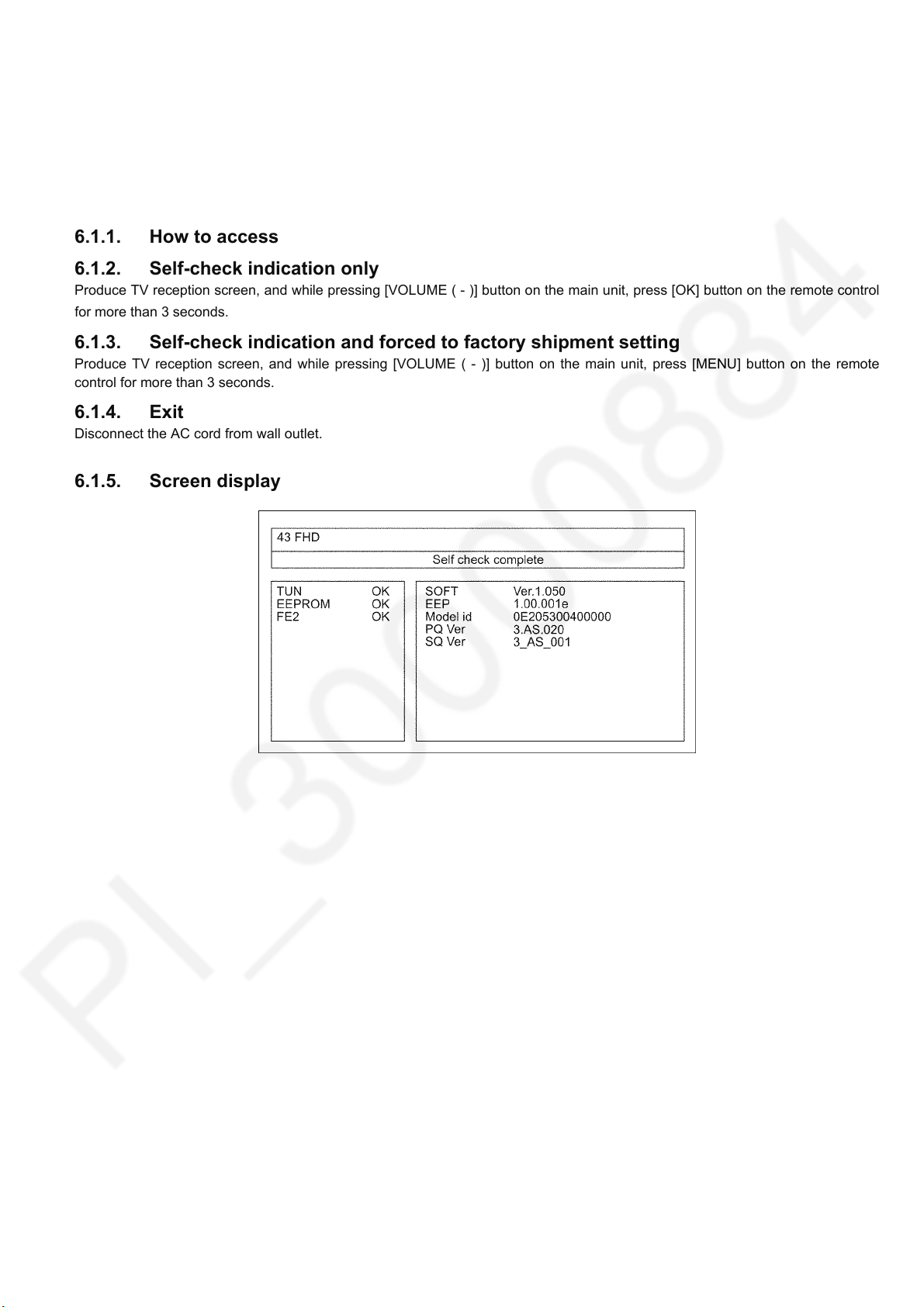
6.1.1. How to access
6.1.2. Self-check indication only
Produce TV reception screen, and while pressing [VOLUME ( - )] button on the main unit, press [OK] button on the remote control
for more than 3 seconds.
6.1.3. Self-check indication and forced to factory shipment setting
Produce TV reception screen, and while pressing [VOLUME ( - )] button on the main unit, press [MENU] button on the remote
control for more than 3 seconds.
6.1.4. Exit
Disconnect the AC cord from wall outlet.
6.1.5. Screen display
11
Page 12
TH-43E460D
6.2. Power LED Blinking timing chart
1. Subject
Information of LED Flashing timing chart.
2. Contents
When an abnormality occurs, the protection circuit will operate and reset the unit to stand by mode. During this time, the
defective block can be identified by the number of blinking times of the Power LED on the front panel of the unit as follow:
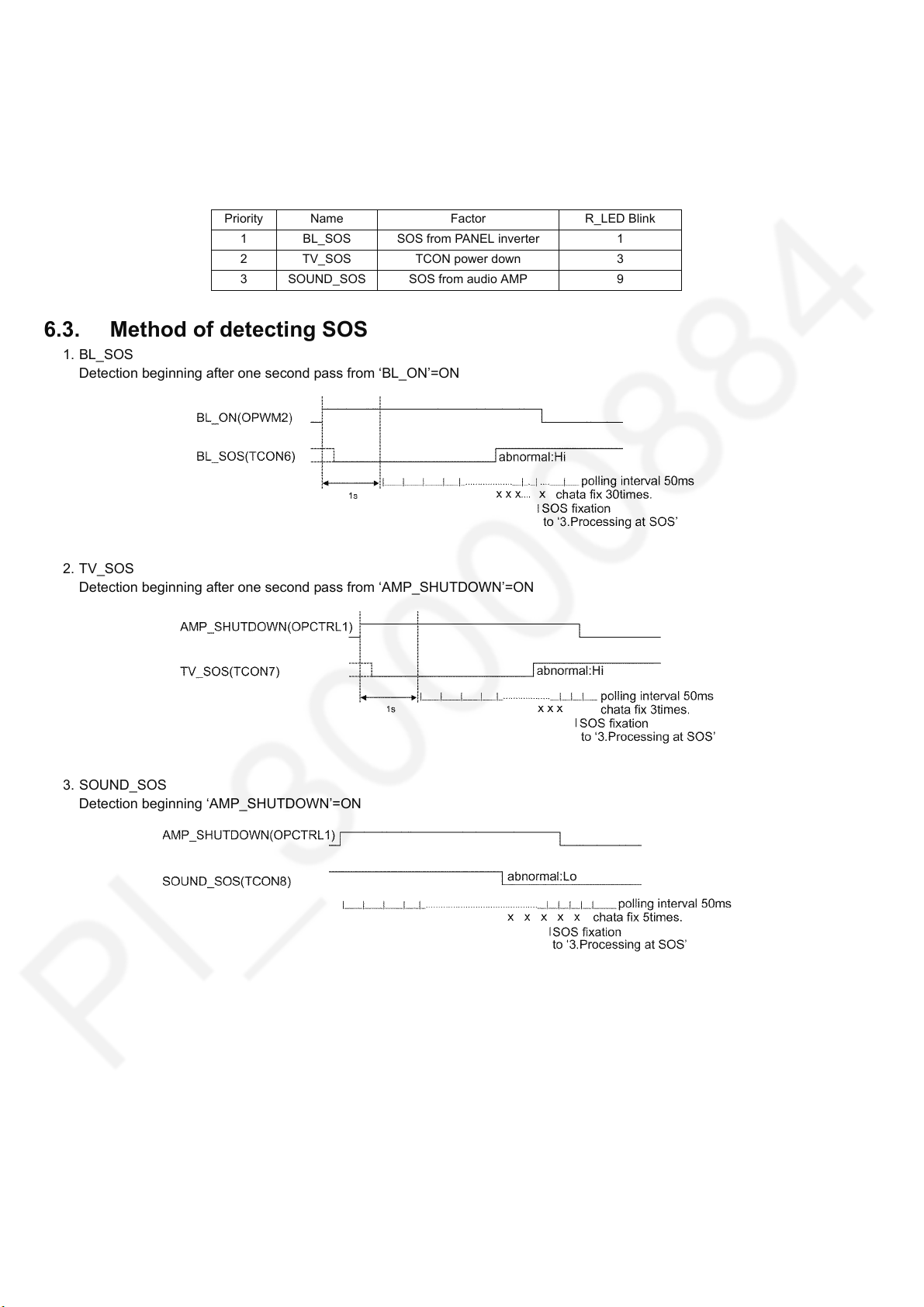
Priority Name Factor R_LED Blink
1 BL_SOS SOS from PANEL inverter 1
2 TV_SOS TCON power down 3
3 SOUND_SOS SOS from audio AMP 9
6.3. Method of detecting SOS
1. BL_SOS
Detection beginning after one second pass from ‘BL_ON’=ON
2. TV_SOS
Detection beginning after one second pass from ‘AMP_SHUTDOWN’=ON
3. SOUND_SOS
Detection beginning ‘AMP_SHUTDOWN’=ON
12
Page 13
6.4. LCD Panel test mode
Purpose:
To find the possible failure point where in LCD Panel or Printed Circuit Board when the abnormal picture is displayed.
How to Enter:
While pressing [VOLUME ( - )] button of the main unit, press [OPTION] button of the remote control three times within 2
seconds.
How to Exit:
Disconnect AC plug from wall outlet.
How to confirm:
If the abnormal picture is displayed, go into LCD Panel test mode to display the several test patterns.
And then, judge by the following method.
Still abnormal picture is displayed: The cause must be in LCD Panel.
Normal picture is displayed: The cause must be in A board.
Remarks:
The test pattern is created by the circuit in LCD Panel.
In LCD Panel test mode, this test pattern is displayed unaffected by signal processing for RF or input signal.
If the normal picture is displayed, LCD Panel must be okay and the cause of failure must be in A board.
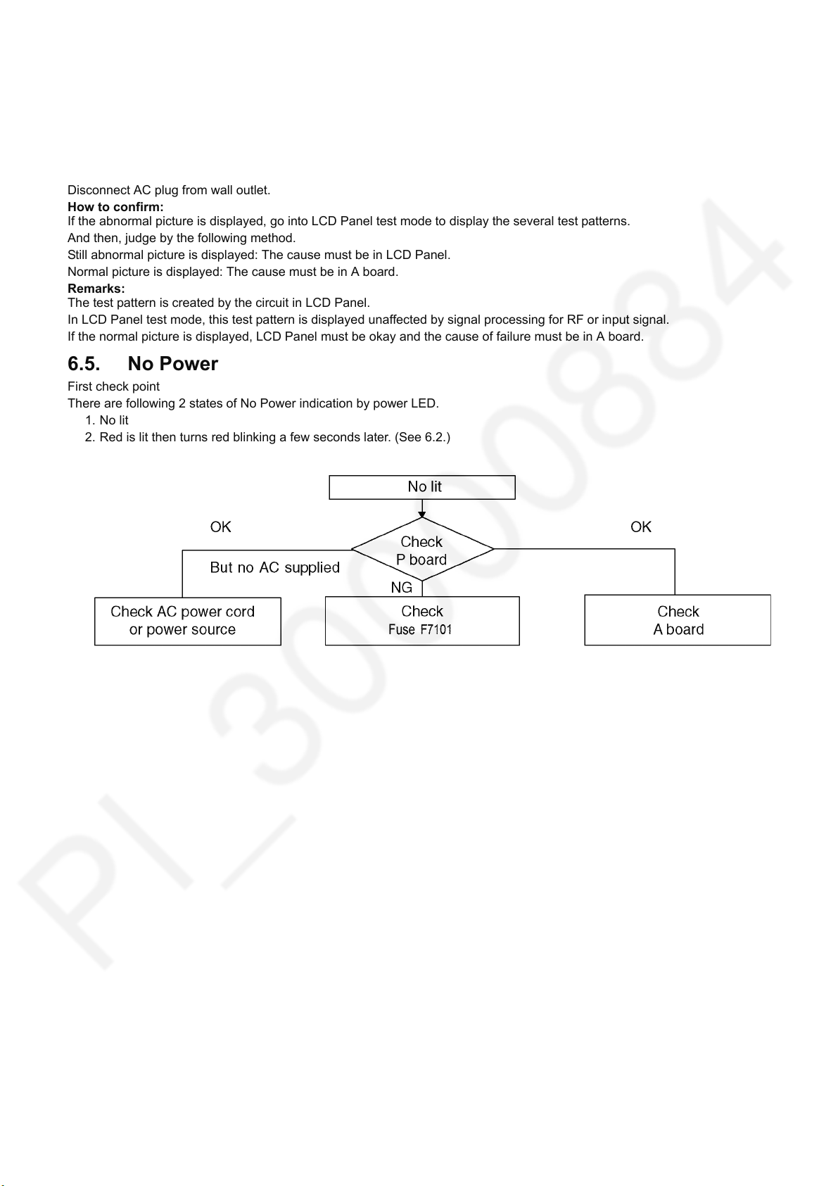
6.5. No Power
First check point
There are following 2 states of No Power indication by power LED.
1. No lit
2. Red is lit then turns red blinking a few seconds later. (See 6.2.)
TH-43E460D
13
Page 14
7 Disassembly and Assembly Instructions
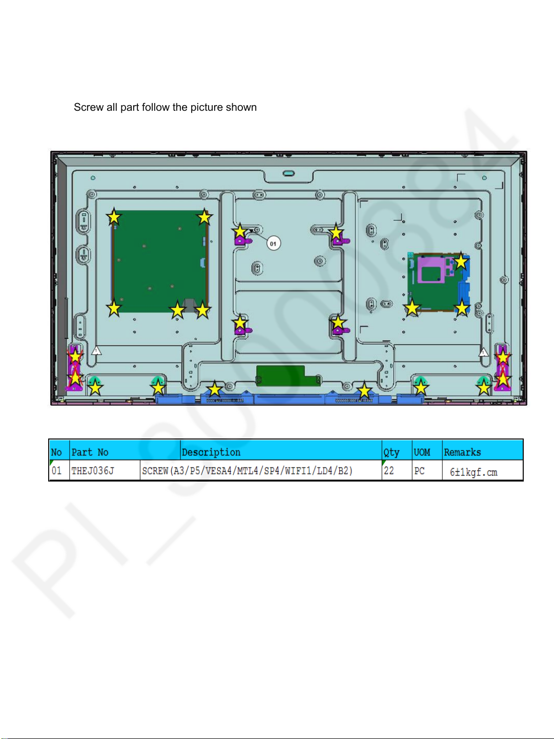
7.1 Screw Installation( Panel)
Screw all part follow the picture shown
TH-43E460D
14
Page 15
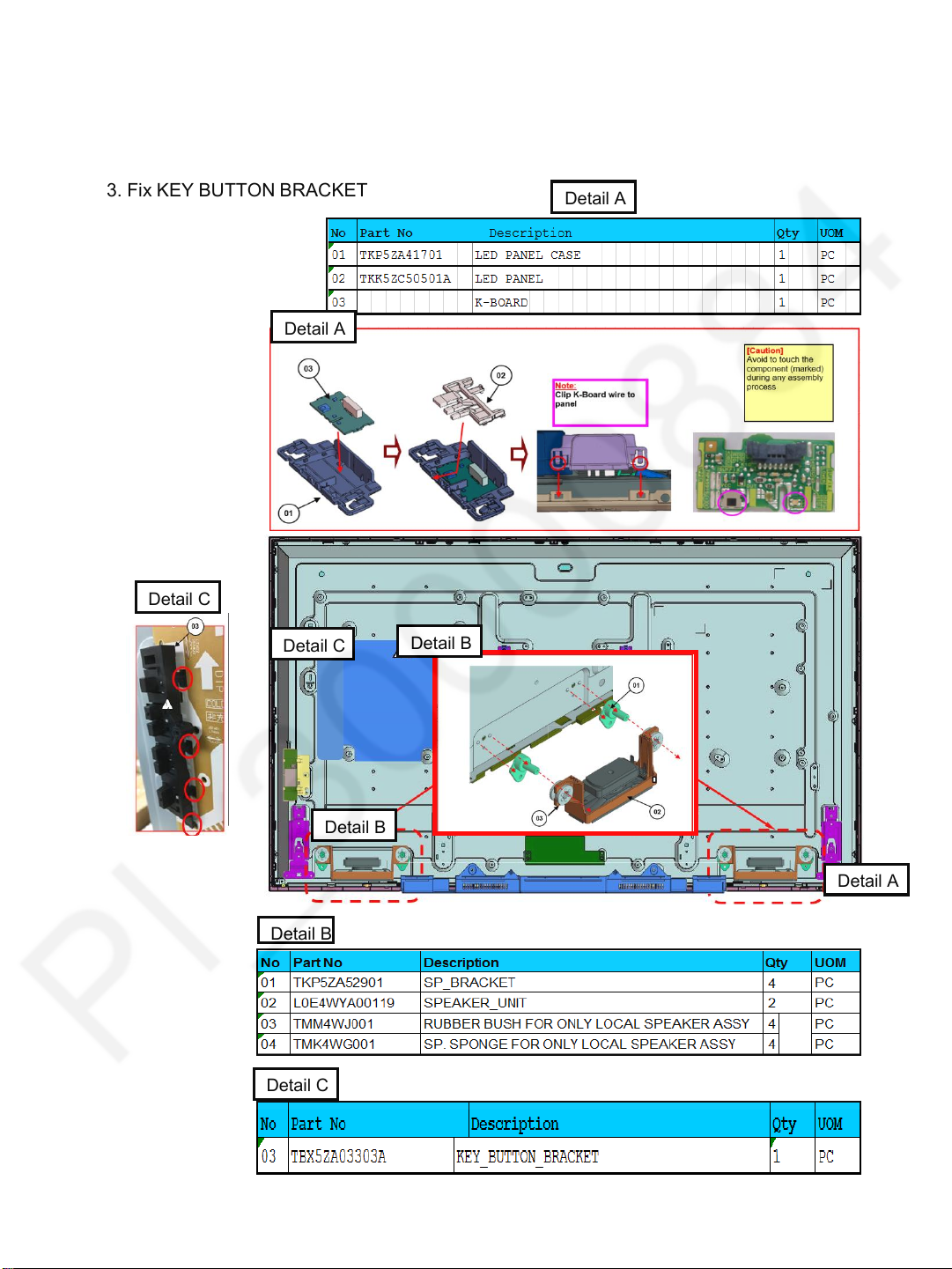
7.2 Key button & LED Assembly
1. Fix SP Bracket
2. Install SP Unit
3. Fix KEY BUTTON BRACKET
Detail A
TH-43E460D
Detail A
Detail C
Detail C
Detail B
Detail C
Detail B
Detail B
Detail A
15
Page 16
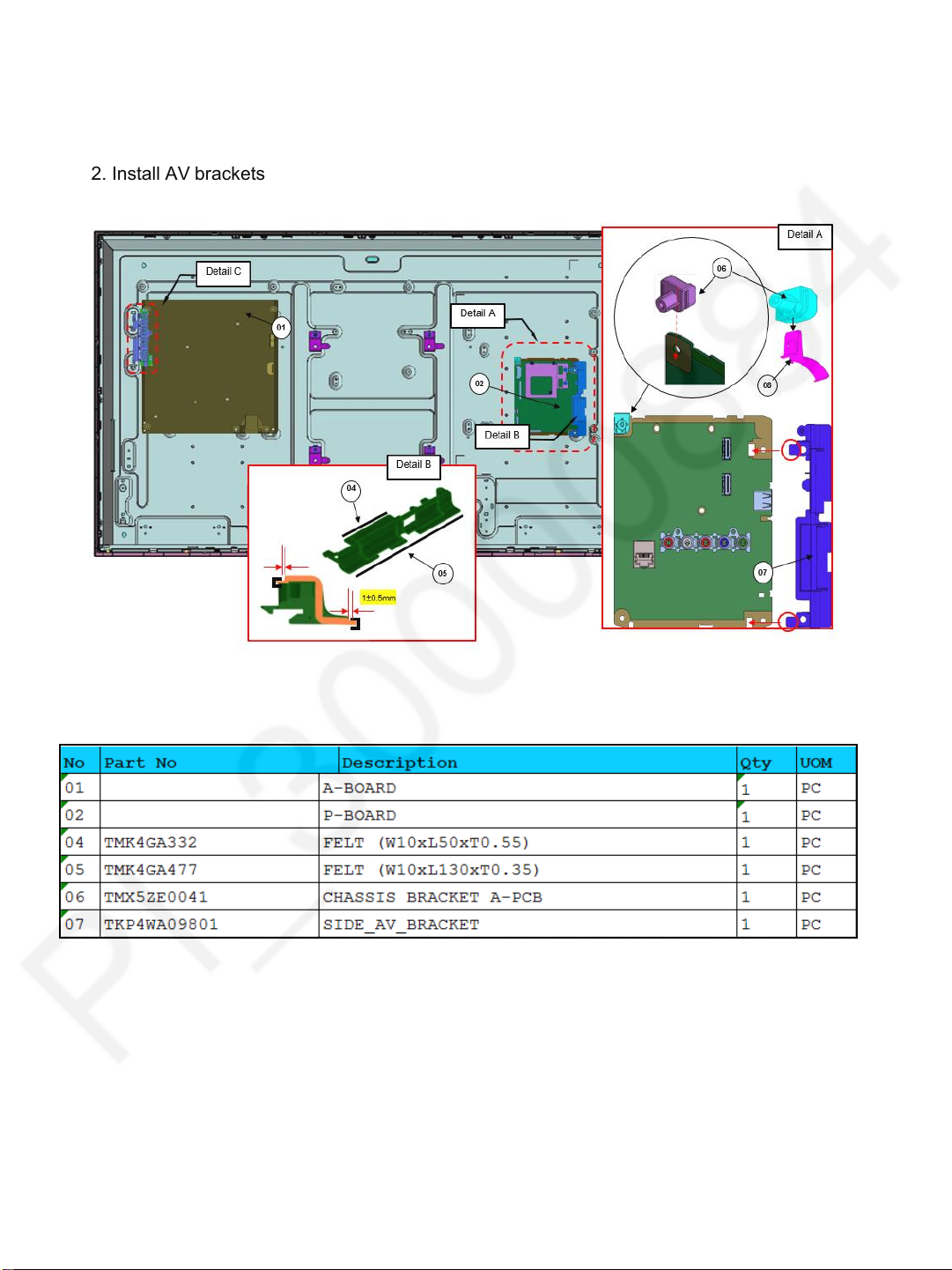
7.3 Side AV BRACKET
1. Fix A,P -board and key button bracket
2. Install AV brackets
TH-43E460D
16
Page 17
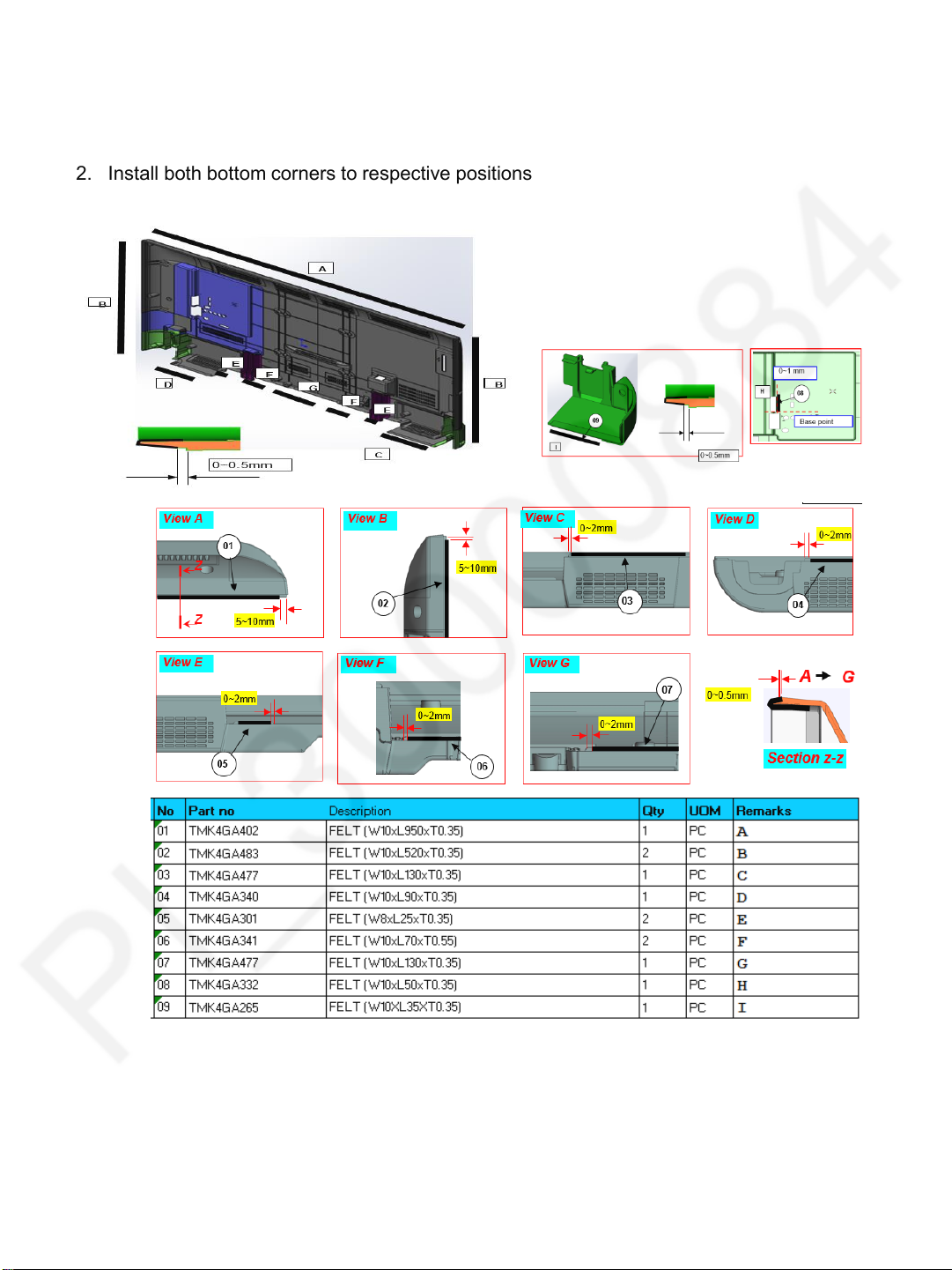
7.4 Felt sticking
1. Stick all felt to back cover and bottom corner R
2. Install both bottom corners to respective positions
TH-43E460D
17
Page 18
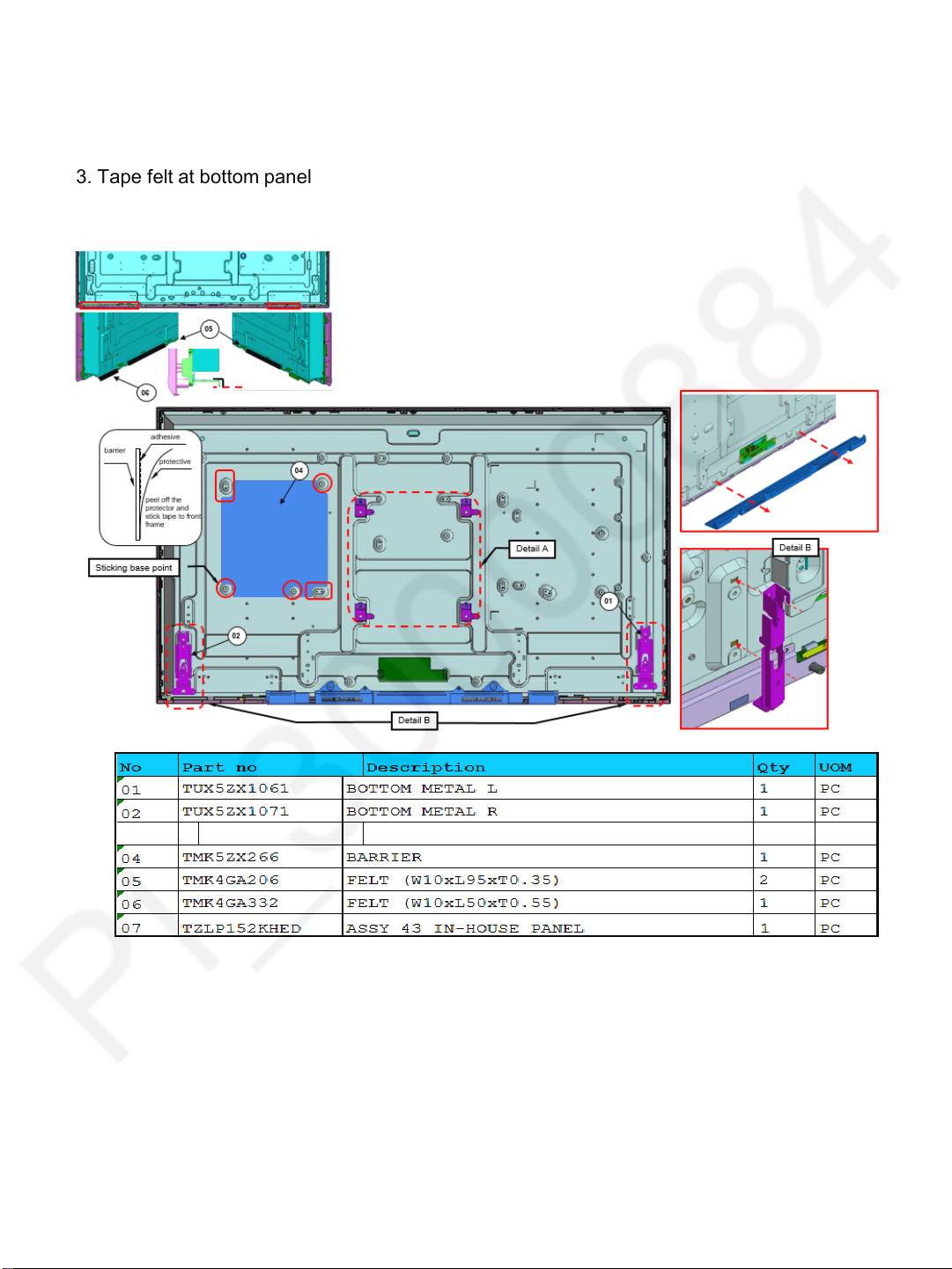
7.5 Vesa Metal & BTM Backcover
1. Fix barrier
2. Install vesa metal & bottom metal
3. Tape felt at bottom panel
TH-43E460D
18
Page 19
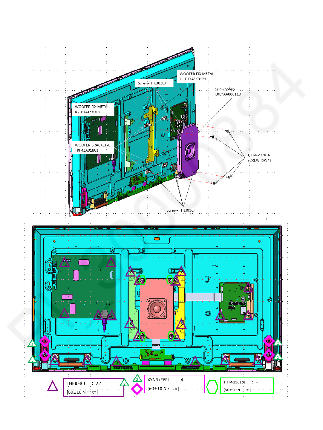
7.6 Sub woofer Assembly
1. Screw all part follow the picture shown
TH-43E460D
19
Page 20
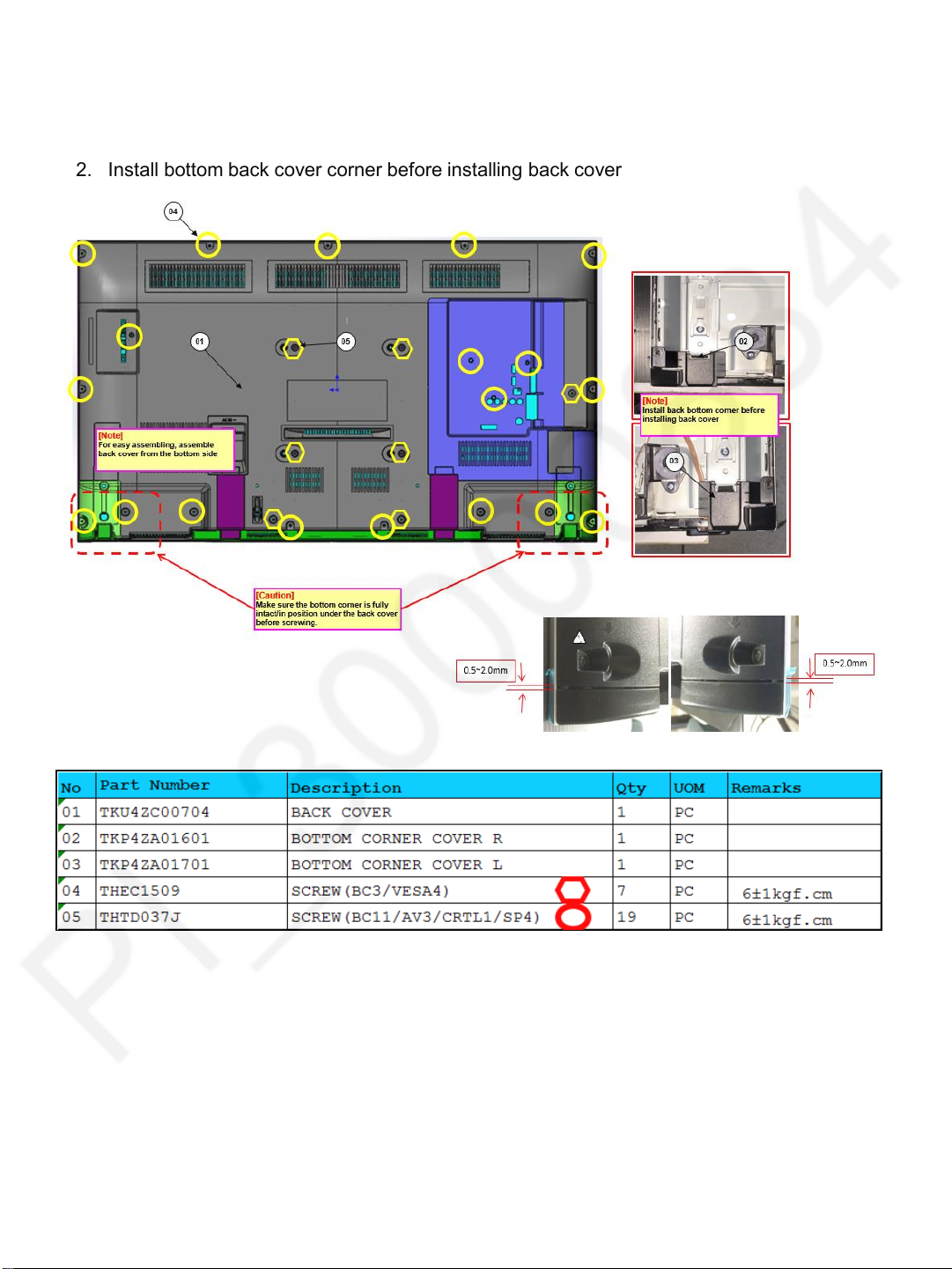
7.7 Backcover
1. Install backcover and fix with screws
2. Install bottom back cover corner before installing back cover
TH-43E460D
20
Page 21

7.8 Label Installation
1. Stick labels and sticker follow accordingly
(rub evently at least twice)
TH-43E460D
21
Page 22
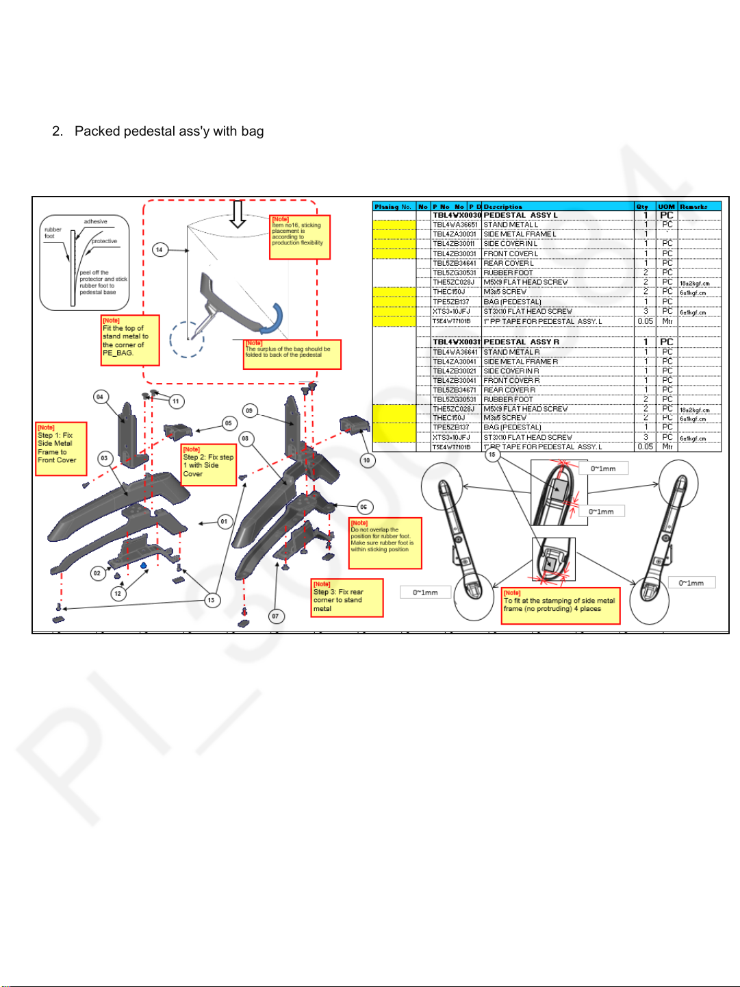
7.9 Pedestal Assembly
1. Install pedestal part follow step 1~3
2. Packed pedestal ass'y with bag
TH-43E460D
22
Page 23

7.10 Accessories Assembly
1) Insert all part into cover for fan bag
2) Direction and sequence (Refer part list for detail)
3) Fold cover for fan bag and stick with masking tape
TH-43E460D
23
Page 24

8 Measurements and Adjustments
8.1. Voltage chart of A-board
Set A-Board to a dummy set and check the satisfaction with the
‘ specified voltage as following table.
8.2. Voltage chart of P-board
Set P-Board to a dummy load and check the satisfaction with the specified
TH-43E460D
voltage as following table.
24
Page 25

TH-49E400Z
PANEL
15V
SP
I2S
Audio AMP
32/40/43/
I2S AMP
SP
49/55”
*&(*&
10W x 2
LVDS
YAMAHA
HD : (DATA 4pairs / CLK 1pair)
15V
single8bit
FHD: (DATA 4pairs / CLK 1pair)
Audio AMP
Sub woofer
I2S AMP
dual8bit
Sub3.3V
YAMAHA
EEP_WP
EEPROM
For E460 series only
64kbit
T2/ISDB/DTMB
SLV[A4]
Australia CAN(LG)
Demod.
TS
Singapore On board (Si2157 )
Low IF
High-side On-board
1.8/3.3V
TUNER
Silicon Lab
switch
USB Slot
IIC USB(side) JK8601
Taiwan
Tunerless
VIDEO/COMPONENT (automatic detection )
MT5561
AV1 JK3100
AUDIO
(HDMI analog audio in)
HDMI 2 (w/ ARC)
DDR2 1G
HDMI1 JK4701
HDMI 1
HDMI2 JK4702
CEC
AV2(side)
VIDEO
AUDIO
JK3002(Prep)
SUB3.3V
SPI
Monitor out JK3000(Prep.)
Op Amp
64/128Mb
Opt. D3051
STB5V
RST
RST
24M
Debug
LED
RMT/KEY
UART
9 Block Diagram
9.1. Main Block Diagram
25
Page 26

10.Wiring Connection Diagram
•11. Do wire dressing follow below spec.
•2. Stick tapes
[Caution]
1.Ensure all connectors
are fully inserted and locked
2.Tapes should be rub
evently at lease twice
3. Make sure no wires are within
screwing positions
TH-43E460D
26
Page 27

11 Schematic Diagram
A - Board : TNP4G610-1 28-41
P - Board : TNPA6382-1 42
K - Board : TNPA6010-1 43
TH-43E460D
Page No.
27
Page 28

3
P3
1
2
2016/12/14
ARR08
CHANGE
Date
Change No.
Common Mng.
Engineering Department
Approved
Described
PAVCKM R&D
-- APPROVE RANGE --
EA
ANODE
K1KY03BA0385
A2010WR0-3P-SW-5E-3.2
VLED ( VF 88.8V)
TP7806
CATHODE
TP7805
0
<
JS7803
<
L7805
47k
R7865
2.4k
R7864
2W
5.6k
R7800
250V
PGNDPGND
C7835
0.01u
250V
1000p
C7836
250V
PGND
C7823
0.01u
250V
1000p
C7822
PGND
J0JYA0000035
2.4k
47k
R7866
R7867
2.4k
R7868
2W
2.4k
R7801
5.6k
R7870
Q7810
2.4k
R7869
B1ABCN000007
100k
R7857
2.4k
R7871
2.0 x 1.25
101
L7807
G0C660Z00001
TP7813
TP7811
R7847
TP7810
<
<
0
L7804
J0JYA0000035
B0FCAM000004
D
0
<
JS7801
<
L7803
*C7815
JS7802
D7800
J0JYA0000035
1kV
470p
Q7801
<
0
TDK-EPC CORPORATION
F1B3A471A098
6
NCNC
N1
NC
5
4
JS7800
<
L7802
J0JYA0000035
B1CERM000055
TK9A20DA,LS1PA2X(M
*R7832
S
1%
180k
1kV
*C7816
*
10
*R7836
47
1%
180k
R7848
100u
160V
C7818
+
<
+
<
47u
160V
C7817
220p
F1B3A221A098
*
S
G
L7801
J0JHC0000075
TP7812
R7849
TUC4GC5042-GND
47k
1.6 x 0.8
R7837
D7803
B0ECKM000053
200k
1%
D7804
47k
DZ2J360M0L
1%
18
R7880
1%
18
R7879
1%
18
R7878
1%
12
R7829
12
R7826
12
R7825
12
R7824
1%
1%
1%
32E7 Vth=0.856V
ILED=Vth/(R7824//R7825//R7826//R7829//R7878//R7879)=380mA
H:
L:
Q7804
B1CFHD000029
S
D
8.2k
2.0 x 1.25
R7830
G
R7842
R7841
2.0 x 1.25
47
R7834
B0BC015A0336
1W
0.22
1W
0.22
2.0 x 1.25
2.0 x 1.25
2.0 x 1.25
2.0 x 1.25
2.0 x 1.25
2.0 x 1.25
33
R7835
D7806
PGND
1
R7887
1
R7886
1
R7885
1
R7884
1
R7883
Q7803
RSP015N10T100
B1CFML000007
D
G
R7823
R7840
470k
S
R7881
1.5k
TP7803
*R7876
OCP:0.4V typ
F1J
50V
C7811
1000p
150
2.0 x 1.25
R7882
AGND
25V
1u
C7809
16
VCC
15
C7808
CS
50V
220p
14
B0ACCD000008
D7805
13
GATE
12
GND
DIMOUT
BD9486F-GE2
11
ISENSE
50V
0.1u
C7810
9
10
FB
RT
R7818
150k
R7816
f=100kHz
2.2k
1%
1%
2.0 x 1.25
D
R7802
Q7806
B1CFHD000029
S
G
100
2.0 x 1.25
R7872
4.7k
C0ZBZ0002199
IC7800
REG502STB3OVP4UVLO5SS
1
1u
25V
C7806
10
200k
R7805
1%
OVP F3.0V
50V
C7805
10k
R7807
0.01u
1%
PWM7CP
6
25V
0.22u
C7803
22k
R7806
18k
R7809
1%
ADIM
8
3.16k
R7862
50V
C7807
1%
0.1u
R7810
18k
1%
AGND (C7806 GND j PGND(R7838 `R7842 GND ) P _
1%
32E7:ILED=380mA
C7804
0.01u
50V
BL-SOS
50V
C7834
F1J
0.1u
C
BL-PWM1
F1J
50V
C7832
C
BL-ON
100p
1
R7873
R7804
0
50V
C7802
0.01u
2.2k
R7803
2.0 x 1.25
50V
C7801
50V
C7800
0.01u
100p
HiZ:
L:
50V
C7535
0.1u
C
F1J
TP7519
16
TP7517
KEY
POWER-ON
12
14
11
13
15
BL-ON
TP7518
10
9
SUB-ON
ECO/PWM2
8
5.3VS
50V
C7534
6
5
7
GND
0.1u
4
16.4V
3
TP7520TP7521 TP7522
2
C
P2
1
SMAW200-H14SP
K1KY14BA0491
YEON HO ELECTRONICS CO., LTD
Page 29

C
F1J
C
50V
C7535
0.1u
C
F1J
TP7519
16
TP7517
KEY
POWER-ON
12
14
11
13
15
BL-ON
TP7518
10
9
SUB-ON
ECO/PWM2
8
5.3VS
50V
C7534
6
5
7
GND
TP7507
F1H
C7532
0.1u
50V
4
16.4V
TP7508
C
0.1u
TP7520TP7521 TP7522
2
3
TP7509
1
F1H
50V
C7531
P2
TP7510
C
0.1u
C
SMAW200-H14SP
K1KY14BA0491
YEON HO ELECTRONICS CO., LTD
D7414
EZJZ1V800AA
C
TP7506
50V
0.1u
C7533
C
F1J
C
25V
10u
*C7557
50V
C2851
0.1u
SW2857
EVQ11G05R
EZJZ1V800AA
D2853
D2854
EZJZ1V800AA
C2852
50V
D2852
C
0.1u
DZ2J068M0L
D7415
EZJZ1V800AA
10u
25V
*C7556
50V
*C7569
5p
C
10u
25V
*C7555
47k
120k
*R7554
36.5k
*R7555
*R7557
5
COMP
FB
6
C
C
C0DBGYY03054
XC6701B532PR-G
g b N X E Z ~ R _ N ^ [ i j
*IC7502
C
2.0 x 1.25
0
R7576
Vss
CE
Vout
3
C
2
25V
*C7505
F1J
1u
1
C
*IC7503
50V
0.022u
*C7503
C
F1H
50V
*C7554
F1J
220p
1%
1%
4
NC
1u
50V
C7564
36V
C
0
JS7507
R7508
750
C
R7509
750
750
R7513
B1CHRE000035
Q7501
C
750
R7514
TPC8134,LPAVQ(S
STBREG
5
25V
*C7504
Vin
1u
50V
*C7562
4700p
50V
*C7561
0.022u
C
*C7560
3
4
GND
SS/HICCUP
C0DBAYY02003
REF8SUBGND9EN
7
25V
*C7563
C
1u
*L7550
G0C270MA0049
1u
25V
2
PDR
LV5980MD-AH
VIN
SW
1
10
50V
*C7552
25V
*C7551
0.1u
10u
*D7550
C
B0JCPE000051
5V DC/DC
1%
2.0 x 1.25
1%
2.0 x 1.25
1%
2.0 x 1.25
1%
2.0 x 1.25
R2852
1.91k
3.09k
R2853
6.04k
R2854
R2855
16.9k
SW2851
EVQ11G05R
EVQ11G05R
SW2852
EVQ11G05R
SW2853
SW2854
EVQ11G05R
EVQ11G05R
SW2855
DZ2J068M0L
D2851
AVUp / + Down / -
TVF
VOL.UP
CH.UP
INPUT
35V
C7508
TP7501
10u
C7506
16V
100k
R7501
*D7507
R7542
4.7u
1.6 x 0.8
15V
100k
C
2.0 x 1.25
JS7505
*D7508
220k
R7502
2.0 x 1.25
C
STBDCDC
*R7552
JW USE v m F
P16.5V
25V
1u
F1J
C7517
*C7565
0.047u
C
F1J
50V
2.2k
R7526
0
15V
R7506
Q7502
B1CHRE000035
TPC8134,LPAVQ(S
C7516
15k
1.6 x 0.8
R7503
47
4.7u
25V
F1H
C7515
50V
2.0 x 1.25
15k
R7504
1u
R7577
D7520
0
1.6 x 0.8
DA2J10100L
R7505
1%
220k
2.0 x 1.25
B1ABBE000003
Q7505
R7532
0
1.6 x 0.8
1.6 x 0.8
C
100k
R7525
C
Digital CH.DN VOL.DN
Analogue
C7501
100p
1kV
TUC4GJ5058-GND
F2AZZ4710003
C7502
+
0
JS7502
D7504
C
B0BC02700041
C7512
L7501
D7503
TP7502
+
+
F2A1E4710124
25V
470u
<
<
J0JYB0000044
*
MBRF20U200CTA-FUP/PED
KEC CORPORATION
B0JBSM000009
D7510
C7513
C
JS7501
0
*C7510
470u
B0BC02700041
25V
1kV
470p
JS7509
TDK-EPC CORPORATION
2200p
3.3k
R7519
F1J
1%
2.0 x 1.25
C7523
50V
R7517
0.1u
2.2k
2.0 x 1.25
KA
200mW
R7523
REF
cathode
47k
2.0 x 1.25
3.3k
R7520
1%
2.0 x 1.25
2
reference
3
1
anode
D7411
DA2J10100L
C
1.6 x 0.8
*R7406
3.9k
50V
0.1u
*C7434
330k
*R7407
1.6 x 0.8
B1CFHF000005
*Q7401
C
1%
20k
R7521
2.0 x 1.25
50V
F1J
C7522
0
C
D7505
B0FBBR000101
SF10KC60M-5009F11
0
JS7508
9
8
7
6
NC
T7301
G4DYA0000571
SANHE-45-038
1
N4
N7
5
4
10
NC
N1,N6
3
2
12
11
13
N2
N3
N5
S
Not specified DC
C7315
1000p
S
1
C
18k
R7515
1.6 x 0.8
0
R7329
F1H
50V
C7314
S
0.022u
B3PAA0000674
*PC7301
2.0 x 1.25
B3PAA0000629
EL816M(B)(ELJ)-V
H1
4.7k
R7516
IC7501
C0DBZYY00545
JW 6G g p
B3PAA0000674
EL816M(B)(ELJ)-V
*PC7300
B3PAA0000629
120k
R7507
1.6 x 0.8
C
COLD
S
HOT
1.6 x 0.8
39k
R7319
50V
C7307
1u
R7408
2.2k
2.0 x 1.25
D7405
S
*PC7302
B3PAA0000674
DA2J10100L
H1
FET v X
B3PAA0000629
R7347
820k
D0GF824JA047
R7346
820k
250V
0.01u
C7317
DARFON ELECTRONICS CORP.
250V
0.01u
C7318
F1J2E103A035
F1J2E103A035
R7355
100
**
R7354
100
**
D0C2101JA140
2W
2W
C7321
100p
D7308
2kV
B0ECKT000012
D7306
100p
C7322
B0ECKT000012
2kV
J0JYA0000035
L7301
R8008ANXCF74
B1CERT000011
*Q7301
1kV
*
*
TUC4GJ5058-GND
D
*
G
<
0
JS7313
68
R7317
D0GD680JA052
1.8k
R7344
TDK-EPC CORPORATION
F1B3A221A098
220p
*C7306
H1
S
680
R7314
10
*R7313
<
J0JYA0000035
D7313
B0ACCD000008
L7316
L7313
470
R7318
J0JYC0000344
D7317
DA2JF2300L
D7315
B0ECKM000053
<
<
8
0
JS7314
L7314
HV
*R7325
2.2
D0GD2R2JA059
J0JYA0000035
D7314
B0BC018A0495
6
R7351
3.2 x 1.6
D7320
Vcc
0.27
1W
ERX1SJR27V
D0C1R27JA104
3.2 x 1.6
3.2 x 1.6
B0JAME000126
47u
C7313
35V
+
470
R7409
5
DRV
C7312
2.0 x 1.25
1u
50V
0.82
R7316
D0GFR82JA020
0.82
R7315
0.82
R7336
D0GFR82JA020
D7316
B0ACCD000008
*R7345
D7303
B0BC01500025
D7323
B0ACCD000008
D0GFR82JA020
220
2.0 x 1.25
D0GD221JA106
R7307
R7305
12k
12k
Q7306
B1ADCE000022
Q7305
B1ADCE000022
D7309
DZ2J047M0L
39k
R7302
R7308
100k
10k
R7306
F1J
50V
C7128
Q7307
D7310
DB2J41100L
DZ2J068M0L
D7307
0.01u
Q7303
B1ABCF000231
B1ABCF000231
Q7302
B1ABCF000231
C7305
C7304
50V
50V
C7316
0.1u
50V
8.2k
R7304
1u
H1
1000p
MAIN
JS7315
IC7301
C0DBBYY00065
NCP1234AD100R2G
1.8k
R7343
1.8k
R7342
0
Latch2FB
1
ZSD
F1J
CS
3
1k
0.01u
2.0 x 1.25
50V
GND
4
F1J
R7320
C7310
j
DZ2J068M0L
D7324
50V
C7311
1000p
ZCD @Ton F62mV
@ @Latch F6.4 `8.0V @
FB i j F3.0 `3.3V
IS i d j F0.9 `1.1V
Tj F125
D7311
DA2J10100L
7.5k
Q7304
R7303
B1ADCE000022
F1J
50V
C7129
68k
R7301
0.01u
<
0
JS7207
TP7202
TP7201
L7208
J0JYA0000039
F1B3A221A098
TDK-EPC CORPORATION
1kV
<
220p
D7215
*C7207
B0HAPR000013
1.5M
R7225
1%
3.2 x 1.6
CHG NO.
START
C7213
47u
450V
F2A2W4700024
+
R72301%44.2k
430k
R7231
1%
1.5M
R7226
1%
3.2 x 1.6
1.5M
R7227
1%
3.2 x 1.6
1.5M
R7228
1%
3.2 x 1.6
R72291%200k
1%
OVP2 FB
820k
R7224
1%
820k
R7234
1%
360k
R7232
H1
TP7204
TP7203
22k
R7220
1.6 x 0.8
R7219
51k
1.6 x 0.8
FLUX
THINNER
BOND FOR CAPACITOR 0.0003(0.3g)/1pcs
PB FREE DIP SOLDER
PB FREE SOLDER
BOND FOR CHIP
SAFEPARTS NO.
CHGNo.
[SINGLE PCB]
for Pb Free
T2KA05512
T8CJ024
T8CC008-1
T8E528-1
T8EJ007
T2KA04200
OTHER PARTS
OTHER PARTS
REFNo.
PRODUCTION
DATE
ARRANGEMENT
PLAN NO.MODEL NO.
APPLIED MODEL
PART NO.
SUB ASSEMBLY
TNPA6076
TOP
201502
18/01/16
18/01/16
20151014
04/08/15
04/08/15
CCWE
YYVE
TNPA6076DA TX-32CSW514
TNPA6076DB TX-32DS503E
TNPA6076DB TX-32DSW504
18/01/16
04/08/15
25/11/16
CKWE
YHUD
TNPA6076DB TX-32DSW504S
TNPA6076EA KE-32E460D
0
JS7203
L7201
J0JYB0000044
<
<
JS7202
D7211
*Q7201
B1CERR000144
TK10A60W,LS1PA4X(M
*
D
0
4.7
2.0 x 1.25
*R7206
FUJI H
B0JCMG000043
*
*
G
3.2 x 1.6
100
S
R7207
1.6 x 0.8
L7207
J0JHC0000075
R7204
100k
JS7208
Q7202
B1ADCE000022
<
<
2.2
1/2W
R7209
0
D7219
B0BC027A0336
100k
R7211
2.0 x 1.25
0.1u
C7208
25V
4.7u
7
8
OUT
VCC
50V
C7206
D7221
6
GND
FA1A02N-C6-L3
C0DBBYY00089
FUJI H
B0ACCD000008
5
CS
C0DBBYY00058
F1J
D7210
C7202
50V
DZ2J047M0L
4700p
FUJI
0.15u
R7202
R7201
47
R7205
D0C1R22JA104
ERX1SJR22V
1W
0.22
1W
0.22
FUJI
0.068
FUJI
D7212
B0JAME000091
SET JW INFO
DC_nil
CHGNo.
RefNO.Pitch
J358 20
JA51 3.1
*JA52 3.1
JA53 3.1
JA54 3.1
JA55 3.1
JA17 3.1
J310 20
J216 15 J314 20
J215 15
J155 10
J154 10
J51 5
J52 5
JA56 3.1
J351 20
J356 20
J357 20
J352 20
J355 20
J354 20
J306 20
J305 20
J304 20
J303 20 J353 20
J252 15
J251 15
J157 10
J156 10 J318 20
J105 10
J102 10
J308 20
J253 15
J161 10
J160 10
J159 10
J158 10
J163 10
J162 10
J153 10
J119 10
J108 10
J152 10
J151 10
J120 10
TNPA5933 T14P-154 2014.6.12 W J
S
TNPA6076-1
TNPA6076
PCB NAME
PRINT TOOL NO.
kamada hatano Y
Watanabe Hatano Y
20141120
2014.12.4
H2 T14P-308
H1 T14P-292
CHG NO. CHANGED BY APPROVED BYREPORT NO. ENDDATE
LA61PWATANABE
BOARD
CHASSIS
COMB.PCB
PARENT NO.
kamada hatano Y
kamada hatano Y
kamada hatano Y
kamada hatano Y
2015.1.8
2015.1.16
2015.3.16
2015/11/6
H3 T15P-005
H4 T15P-024
H5 T15P-132
H6 TR15-0250
SEKIMOTO
CHECKED BY
DESIGNED BY
iwabuchi kato N
2016/03/02
H7 TR16-0075
IWABUCHI
WATANABE
APPROVED BY
CIRCUIT DRAWING
MANAGER
PFC
10 1
TP7106
TP7105
PFC
N1
4
G4DYA0000465
T7202
C7209
ECWFD2W824KC
0.82u
S
IC7201
FB
COMP3RT
1
5
NC
NC NC
6
2
OVP
4
F1J
50V
C7205
0.01u
F1J
F1J
50V
C7214
50V
C7201
0.01u
FUJI
1000p
H2
S
R7203
100k
2.0 x 1.25
C
C
ZA7102
K4AD01A00004
C
i E A [ X O [ q
K4AD01A00003
ZA7104
K4AD01A00003
K4AD01A00004
C
i A [ X O [ qAC C b g
i A [ X O [ q
ZA7103
K4AD01A00004
C
K4AD01A00003
ZA7101
i A [ X O [ q
K4AD01A00004
K4AD01A00003
C
2.2M
R7240
3.2 x 1.6
2.2M
R7241
3.2 x 1.6
2.2M
R7242
3.2 x 1.6
F1J
50V
C7220
0.01u
2.2M
R7243
3.2 x 1.6
R7244
120k
FUJI
F1H
2.0 x 1.25
50V
C7211
R7212
F1H
1000p
1.6 x 0.8
22k
FUJI
0.1u
C7203
50V
C7204
0.47u
F1H
16V
FUJI
0.15u
TP7108
TP7107
L7000
J0JYB0000044
D7108
B0HAGQ000001
S
+
1
*D7106
2
`
3
`
B0FBAR000047
D6JBB60V-7009F01
4
S
*R7335
*CF7101
D4CA94R0A001
10M1WD0XB106JA018
S
S
J0JYA0000035
L7100
470p
C7132
S
S
1M
R7104
Not specified DC
R7103
S
1M
R7101
S
S
LF7103
<
G0B183GA0082
0
JS7104
<
1
23
L.F L.F
0.22u
4
0
<
JS7108
S
C7102
C7105
Not specified DC
470p
Not specified DC
S
470p
C7103
S
S
Not specified DC
LF7104
G0B183GA0082
<
D7107
S
ERZVA7V471
0
JS7106
S
1
23
S
4
Not specified DC
Not specified DC
S
C7130
220p
S
220p
C7131
LF7105
<
1
<
L.F
4
G0B350GA0083
0
<
23
JS7107
<
S
D7101
ERZE08C621CD
1M
R71081MD0GF105JA048
TP7104
D0GF105JA048
R7106
S
TP7103
S
R7107 1M
TP7102
D0GF105JA048
S
C7104
HOLDER
NO
K5E502YYA162
K5E502YYA213
470p
C7101
S
TP7101
Not specified DC
0.22u
S
*F7101
L N
TP7100
Not specified DC
S
K2AAYA000003
K2AAYA000004
*JK7101
K2AAYA000005
AC-059-02-PPE(PC8)
AC line
C
1M
R7102
1M
EA
TNPA6076.p.cir/001.sht
16/12/14 12:35:17 Kamariah
SHEET
PLOT
VARIATION
Page 30

SHEET
PLOT
VARIATION
0.01u
16/12/14 12:34:26 Kamariah
AE
TNPA6010.K.cir/001.sht
Refno. List(PCB)
------------------------------------- USED -------------------------------------
C 2800-2807 2809 2810
D 2800-2805 2800A 2800B
KA 10
Q 2800-2802
R 2800-2813(suffix) 2820-2823
RM 2800
SN 2800
TP 2800-2804 2806-2809
------------------------------------- USED -------------------------------------
14 N f p K v g
s o @120802
H m F
KM v ] DCHKLAND _131009
*C2800
50V
0.01u
50V
R_LED_ON
G_LED_ON
STBY 3.3
AI
SUB3.3V
GND
REMOTE
K1KY07BA0483
K10
12507WR-H07G
7
6
5
4
3
2
1
C1
*C2806
*C2803
50V
*C2802
50V
0.01u
0.01u
0.0001SOLDER
C1
C1
C1
C1
0.0001
CREAM SOLDER
[DOUBLE PCB]
PARTS NO. CHGNo.
T2KA05512
T2KC03600
RE-FLOW EDIP for Pb Free
OTHER PARTS
REFNo. SAFE
A10
REC_LED
50V
C2805
0.01u
DOUBLE PITCH
C1
<
G
R
<
*D2802
B3AGB0000083
*D2802A
B3AAB0000379
1k
*R2824
1%
4.3k
*R2823
1%
G_LED_ON
R_LED_ON
p X R 2cm z u
i @WW-B3J-A0006
AI_SENSOR POWER_LEDRM_RECEIVER
16V
0.1u
*C2804
1
2
SW
VCC
GND4IOUT
3
C1
TNPA5915
R2822 W p [ A
*SN2800
B3JB00000223
*R2821
C1
C1
16V
0.1u
*C2808
2.0 x 1.25
C1
8.2k
*R2822
2125 T C Y K {
0
l R (MTK)
l R iPro4 j
400lx x O a
56k:15k
68k:3k
l R (LD6)
100k:3.3k
STB3.3V
s n o @B3RBB0000018 @ V [ v
r h c d @WW-B3R-A0013 @ V ` Y
OUT
GND
B3RBB0000018
GND
(CASE)
VCC
RM2800
*R2820
47
C1
C1
0.01u
*C2801
50V
C1
*D2800
DZ2J056M0L
C1
C2807
10u
10V
^ z _131022
Page 31

IC8001 J9 VCCK
IC8001 K5 VCCK
IC8001 K6 VCCK
IC8001 K7 VCCK
IC8001 K8 VCCK
IC8001 L1 VCCKIC8001 Y10 AVDD10_LDO
IC8001 L2 VCCK
IC8001 L3 VCCK
IC8001 L4 VCCK
IC8001 L5 VCCK
IC8001 L6 VCCK
IC8001 L7 VCCK
IC8001 L8 VCCK
IC8001 M7 VCCK
IC8001 M8 VCCK
IC8001 N1 DDRV
IC8001 N2 DDRV
IC8001 N3 DDRV
IC8001 N4 DDRV
IC8001 N6 DDRV
IC8001 N7 DVSS
IC8001 N8 DVSS
IC8001 N9 DVSS
IC8001 N11 DVSS
IC8001 N12 DVSS
IC8001 N13 DVSS
IC8001 N15 DVSS
IC8001 N16 DVSS
IC8001 P7 DVSS
IC8001 P11 DVSS
IC8001 P12 DVSS
IC8001 P14 DVSS
IC8001 R6 DVSS
IC8001 R11 DVSS
IC8001 R12 DVSS
IC8001 R13 DVSS
IC8001 R14 DVSS
IC8001 T5 DVSS
IC8001 T13 DVSS
IC8001 T15 DVSS
IC8001 U16 DVSS
IC8001 V16 DVSS
IC8001 W19 DVSS
IC8001 Y3 DVSS
C
VCCK
IC8001 Y4 AVDD12_ETH
IC8001 H20 AVDD12_HDMI_1
IC8001 Y5 AVDD12_HDMI_0
AVDD1.2V
POWER/GROUND
IC8001 Y20 AVDD12_DEMOD
AVDD1.20V
CM1
4.7u
C8850
6.3V
C
IC8001 R10 AVDD33_HDMI
IC8001 T17 AVDD33_REG_STB
IC8001 R9 AVDD33_ETH
3V3SB
AVDD3V3
IC8001 U17 AVDD33_VIDEO_STB
IC8001 V17 AVDD33_RGB_STB
IC8001 M16 AVDD33_ADAC
IC8001 M14 AVDD33_AADC
33AVDD
DDRV
IC8001 L15 AVDD33_CAP
33AVDD
IC8001 T12 AVSS33_RGB
IC8001 N14 AVSS33_CLN
IC8001 T14 AVSS33_VIDEO
1M
R8098
0
R8120
P_XTALO
27p
C8140
AXO
C
50V
9/6 @X8301 i X C8300 10p->6p C8301 10p->7p X i U ] T j
R8300 1M A R p ^ [ (2010/5/17)
P_XTALI
AXI
A1 DVSS
C1AB00004200
IC8001 N10 VCC3IO
IC8001 P9 VCC3IO
IC8001 P10 VCC3IO
C
IC8001
IC8001 A8 DVSS
IC8001 F6 DVSS
IC8001 F20 DVSS
IC8001 G7 DVSS
IC8001 G8 DVSS
IC8001 G18 DVSS
IC8001 H9 DVSS
IC8001 H10 DVSS
IC8001 H11 DVSS
IC8001 H12 DVSS
IC8001 H13 DVSS
IC8001 H14 DVSS
IC8001 H16 DVSS
IC8001 J7 DVSS
IC8001 J10 DVSS
IC8001 J11 DVSS
IC8001 J12 DVSS
IC8001 J13 DVSS
IC8001 K9 DVSS
IC8001 K10 DVSS
IC8001 K11 DVSS
IC8001 K12 DVSS
IC8001 L9 DVSS
IC8001 L10 DVSS
IC8001 L11 DVSS
IC8001 L12 DVSS
IC8001 L13 DVSS
IC8001 M1 DVSS
IC8001 M2 DVSS
IC8001 M4 DVSS
IC8001 M5 DVSS
IC8001 M6 DVSS
IC8001 M9 DVSS
IC8001 M10 DVSS
IC8001 M11 DVSS
IC8001 M12 DVSS
IC8001 M13 DVSS
C
H0J240500095
/ 20/30ppm BMTK d l<=30ppm
C8142
X8301
JF3225SEAM 24.000MHZ20P
27p
50V
DVSS GND
DVDD3.3V
Other
C
R8151
P_OPCTRL0
C
R8146
P_PACLE
10k
4.7k
STRAPPING MODE
must set PD
SoC z u
C
R8130
P_FSRC_WR
4.7k
R8148
C
10k
P_ADIN0
C
75
R8147
P_VDAC_OUT
R8104
P_ZQ
KAMARIAH MR BISWAS N
KAMARIAH MR BISWAS N
KAMARIAH MR BISWAS N
2016/12/08
TR16-0429
15/09/16
28/11/16
08/12/16
CHANGE
PAVCKM R&D
Engineering Department
Date
Approved
Change No.
H1 TR16-0328
H2 TR16-0429
H3 TR16-0452
CHG NO. CHANGED BY APPROVED BYREPORT NO. ENDDATE
C
1%
240
C
CV8
1u
C8196
P_CVBS_COM
16V
C
CM28
C8148
P_VMID_AADC
1u
16V
Described
Common Mng.
-- APPROVE RANGE --
nil DA DB DC DE DF DG DJ DH
DD DK
IC8001 D9 CI_A0
CI GPIO
IC8001 V19 XTALI
IC8001 C9 CI_A1
IC8001 W20 XTALO
IC8001 F10 CI_A2
IC8001 A10 CI_A3
IC8001 D10 CI_A4
IC8001 E10 CI_A5
IC8001 B12 CI_A6
IC8001 D12 CI_A7
IC8001 C16 CI_A8
IC8001 C17 CI_A9
IC8001 B18 CI_A11
IC8001 A19 CI_A10
IC8001 L16 RF_AGC
IC8001 Y19 ADCINN_DEMOD
IC8001 A15 CI_A14
IC8001 E9 CI_A12
IC8001 B16 CI_A13
IC8001 W18 ADCINP_DEMOD
IC8001 D16 CI_MISTRT
IC8001 B13 CI_MIVAL
IC8001 D14 CI_MCLKI
P_CI_MISTRT
P_CI_MIVAL
P_CI_MCLKI
IC8001 C15 CI_MDI1
IC8001 A16 CI_MDI0
P_CI_MDI0
P_CI_MDI1
IC8001 C13 CI_MDI3
IC8001 C14 CI_MDI2
P_CI_MDI3
P_CI_MDI2
IC8001 H19 USB_DM0
IC8001 H18 USB_DP0
IC8001 E12 CI_MDI5
IC8001 A13 CI_MDI4 IC8001 N5 DDRV
IC8001 F12 CI_MDI6
P_CI_MDI4
P_CI_MDI5
P_CI_MDI6
IC8001 G19 USB_DM1
IC8001 F19 USB_DP1
IC8001 E13 CI_MDI7
IC8001 B8 CI_D0
P_CI_MDI7
IC8001 D13 CI_D1
IC8001 F9 CI_D2
IC8001 E17 CI_D3
IC8001 E19 CI_D4
IC8001 D20 CI_D5
IC8001 Y2 TXVP
IC8001 D18 CI_D6
IC8001 Y1 TXVN
IC8001 B20 CI_D7
IC8001 W3 RXVP
IC8001 E11 CI_MDO0
IC8001 E7 CI_MDO1
IC8001 W4 REXT_ETH
IC8001 W2 RXVN
IC8001 E16 CI_MDO3
IC8001 E8 CI_MDO2
IC8001 E20 CI_MDO4
IC8001 D19 CI_MDO5
IC8001 C20 CI_MDO6
IC8001 C19 CI_MDO7
IC8001 B19 CI_CE1#
IC8001 C18 CI_OE#
IC8001 E4 TCON0
IC8001 B15 CI_WE#
IC8001 D11 CI_MOSTRT
IC8001 C2 TCON2
IC8001 F2 TCON1
IC8001 C10 CI_MOVAL
IC8001 A12 CI_MCLKO
IC8001 C1 TCON4
IC8001 E3 TCON3
IC8001 F11 CI_IREQ#
IC8001 C11 CI_WAIT#
IC8001 F3 TCON6
IC8001 D1 TCON5
IC8001 E18 CI_CD1#
IC8001 F7 CI_CD2#
IC8001 F1 TCON8
IC8001 D2 TCON7
IC8001 D17 CI_IOWR#
IC8001 A18 CI_IORD#
IC8001 B10 CI_REG#
IC8001 C12 CI_RESET
IC8001 F18 CI_PWR_EN
IC8001 T7 ADIN0
IC8001 P8 ADIN1
IC8001 U8 ADIN2
IC8001 U6 ADIN3
IC8001 T8 ADIN4
IC8001 U5 ADIN5
IC8001 T6 ADIN6
IC8001 R8 ADIN7 IC8001 M3 DVSS
IC8001 R1 AOBCK
IC8001 R2 AOMCLK
IC8001 P3 AOLRCK
IC8001 T4 AOSDATA1
IC8001 R3 AOSDATA0
IC8001 R4 ASPDIFO
IC8001 F16 ASPDIFI
IC8001 R20 AIN_R0
IC8001 U20 AIN_L0
IC8001 V20 AIN_L1
IC8001 R17 AIN_R1
IC8001 T20 AIN_L2
IC8001 R19 AIN_R2
IC8001 R18 AIN_R3
IC8001 T19 AIN_L3
IC8001 T16 VMID_AADC
IC8001 T18 AL1_ADAC
IC8001 R16 AL0_ADAC
IC8001 U19 AR1_ADAC
IC8001 P16 AR0_ADAC
IC8001 P2 ZQ
P_XTALI
P_XTALO
CLK/Crystal
IC8001 Y9 HDMI_0_RX_2
IC8001 V8 HDMI_0_RX_0
IC8001 U9 HDMI_0_RX_1B
IC8001 V7 HDMI_0_RX_0B
IC8001 V9 HDMI_0_RX_1
Miscellaneous
DEMOD
IC8001 W7 HDMI_0_RX_CB
IC8001 W9 HDMI_0_RX_2B
IC8001 Y7 HDMI_0_RX_C
P_IF_AGC
P_ADCINN_DEMOD
IC8001 N18 HDMI_1_RX_1B
IC8001 N17 HDMI_1_RX_1
IC8001 P18 HDMI_1_RX_0B IC8001 J15 IF_AGC
IC8001 P17 HDMI_1_RX_0
P_HDMI_1_RX_0
P_HDMI_1_RX_1
P_HDMI_1_RX_1B
P_HDMI_1_RX_0B
P_ADCINP_DEMOD
IC8001 M20 HDMI_1_RX_2B
IC8001 P19 HDMI_1_RX_C
IC8001 M19 HDMI_1_RX_2
P_HDMI_1_RX_2
IC8001 P20 HDMI_1_RX_CB
P_HDMI_1_RX_2B
P_HDMI_1_RX_CB
P_HDMI_1_RX_C
USB
IC8001 L18 HDMI_2_RX_0B
IC8001 K18 HDMI_2_RX_0
P_HDMI_2_RX_0
IC8001 K20 HDMI_2_RX_1B
IC8001 K19 HDMI_2_RX_1
P_HDMI_2_RX_1B
P_HDMI_2_RX_1
P_HDMI_2_RX_0B
P_USB_DM0
P_USB_DP1
P_USB_DP0
IC8001 J19 HDMI_2_RX_2
P_HDMI_2_RX_2
P_USB_DM1
IC8001 J20 HDMI_2_RX_2B
IC8001 M17 HDMI_2_RX_C
IC8001 M18 HDMI_2_RX_CB
P_HDMI_2_RX_2B
P_HDMI_2_RX_CB
P_HDMI_2_RX_C
Ethernet
IC8001 G17 GPIO2
IC8001 B1 GPIO0
IC8001 E5 GPIO1
P_GPIO0
P_GPIO1
P_GPIO2
General Purpose Input
and Output(GPIO)
IC8001 H5 GPIO3
IC8001 H4 GPIO4
P_GPIO3
IC8001 F17 GPIO5
P_GPIO5
P_TCON1
PANEL_WP
P_TCON2
P_TCON3
P_TCON4
P_TCON5
P_TCON6
P_TCON7
TCOM
IC8001 W17 VDAC_OUT
P_VDAC_OUT
Analog Video Output
Analog Video Input
P_TCON8
IC8001 U15 PB0
P_PB0
IC8001 W16 PR0
P_PR0
P_ADIN0
Servo ADC input
IC8001 U14 Y0
P_Y0
IC8001 V14 SOY0
IC8001 V15 COM0
P_COM0
P_SOY0
IC8001 V18 CVBS0
IC8001 W14 PB1
IC8001 Y14 PR1
P_ADIN2
P_ADIN1
IC8001 V13 Y1
IC8001 U13 COM1
IC8001 U12 SOY1
IC8001 Y17 CVBS1
IC8001 Y16 CVBS_COM
P_CVBS1
P_CVBS_COM
IC8001 U11 SOG
P_ZQ
P_TCON9
Audio
IC8001 V11 BP
IC8001 W12 GP
IC8001 V10 VSYNC
IC8001 V12 RP
IC8001 U10 HSYNC
IC8001 Y12 COM
PC
P_TCON10
Open or PD(?ohm)
P_ASPDIFI
P_ASPDIFO
P_AOSDATA1
check with MTK san
P_AIN_R0
P_AIN_L0
P_AIN_R2
P_AIN_L2
Audio Line in ADC
P_VMID_AADC
P_AL0_ADAC
Audio DAC
P_AR0_ADAC
Other
IC8001 W10 ORESETB
IC8001 A20 FSRC_WR
P_ORESETB
P_FSRC_WR
Miscellaneous
IC8001 G4 PDD1
IC8001 G2 PDD0
P_PDD1
P_PDD0
IC8001 K3 PDD2
IC8001 G3 PDD3
IC8001 H3 PDD4
IC8001 J6 PDD5
IC8001 G1 PDD6
P_PDD6
IC8001 J3 PDD7
IC8001 J4 POCE0#
P_PDD7
P_POCE0#
IC8001 J2 POCE1#
P_POCE1#
Serial/NAND flash/EMMC
IC8001 K4 PARB#
IC8001 K2 PAALE
IC8001 J5 POWE#
IC8001 K1 PACLE
P_PACLE
IC8001 J1 POOE#
P_POOE#
UART
IC8001 U2 U0RX
IC8001 U1 U0TX
P_U0RX
P_U0TX
IIC
IC8001 P5 OSDA0
IC8001 R5 OSCL0
P_OSCL0
P_OSDA0
IC8001 F5 OSDA1
IC8001 F4 OSCL1
P_OSCL1
P_OSDA1
PWM
IC8001 G5 OPWM1
IC8001 E6 OPWM0
P_OPWM1
P_OPWM0
IC8001 G6 OPWM2
P_OPWM2
IC8001 T3 OIRI
P_OIRI
Infrared
IC8001 V2 OPCTRL1
IC8001 U3 OPCTRL0
IC8001 V3 OPCTRL2
P_OPCTRL2
P_OPCTRL1
P_OPCTRL0
IC8001 V1 OPCTRL3
P_OPCTRL3
IC8001 T2 OPWRSB
IC8001 U4 OPCTRL4
P_OPWRSB
P_OPCTRL4
IC8001 K16 HDMI_CEC
P_HDMI_CEC
Power Management
IC8001 V6 HDMI_0_SDA
IC8001 W5 HDMI_0_HPD
IC8001 U7 HDMI_0_SCL
P_HDMI_0_SCL
P_HDMI_0_SDA
P_HDMI_0_HPD
IC8001 K14 HDMI_1_SDA
IC8001 L17 HDMI_1_HPD
IC8001 J18 HDMI_1_SCL
P_HDMI_1_SCL
P_HDMI_1_HPD
P_HDMI_1_SDA
IC8001 J14 HDMI_2_SDA
IC8001 J17 HDMI_2_SCL
IC8001 J16 HDMI_2_HPD_CBUS
P_HDMI_2_SCL
P_HDMI_2_SDA
P_HDMI_2_HPD_CBUS
IC8001 K15 MHL_SENCE
IC8001 V5 VGA_SCL
IC8001 V4 VGA_SDA
P_VGA_SCL
P_VBA_SDA
IC8001 P1 DDRVREF
P_DDRVREF
DDR3 interface
IC8001 D6 AE0N
IC8001 A6 AE1P
P_AE0N
P_AE1P
IC8001 B6 AE1N
P_AE1N
IC8001 C6 AE0P
P_AE0P
LVDS/EPR/VB1
IC8001 D7 AE2N
IC8001 C7 AE2P
P_AE2P
P_AE2N
IC8001 C8 AE3P
IC8001 D8 AE3N
P_AE3P
P_AE3N
IC8001 A2 AO0P
IC8001 B2 AO0N
P_AO0P
P_AO0N
IC8001 C3 AO1P
P_AO1P
IC8001 D3 AO1N
IC8001 C4 AO2P
P_AO1N
P_AO2P
IC8001 D4 AO2N
P_AO2N
IC8001 C5 AO3P
IC8001 D5 AO3N
P_AO3N
P_AO3P
IC8001 B4 AOCKN
IC8001 A4 AOCKP
P_AOCKN
P_AOCKP
Page 32

SITU_3.3V
SITU_1.8V
SITU_ALIF_P
SITU_ALIF_N
SITU_DLIF_P
SITU_DLIF_N
SITU_SDA
SITU_SCL
SITU_IFAGC2
SITU_IFAGC1
SITU_RST
SITU_T2FEF
L O GPIO2 [ q NC
8/27 DVB-T2& I { [ h K v
I { [ h p iTuner Pin z u j
L6779
L6778
L6777
G1CR22JA0097
G1CR22JA0097
0.01u25V
0.01u25V
C6770
p X R S Pin z u
C6769
C
50V1000p
C6768
L6775
G1CR22JA0097
0.01u25V
C6771
C6772
C
50V1000p
C6798
G1CR22JA0097
0.01u25V
C
50V1000p
C6797
C1AB00004172
IC6750
SI2157-A30-GMR
8
9
10
11
12
13
14
VDD_L
XOUT
XTAL_I
XTAL_O
GND
VDD_H
VDD_H
22
C6791
1000p
15
16
17
18
19
20
21
C
50V
X6750
H0J240500067
24MHz
C
TXC
C
C6790
50V
C6789
50V
180p
180p
0.1u
16V
1000p
50V
L6773
G1CR27JA0097
L6776
N
N
C6774
C6773
G1CR27JA0097
ALIF_P
LDO_ADJ
RF_IP24RF_IN
23
ALIF_N
VDD_H
Pad
VDD_D
GND
C6792
DLIF_N
GPIO1
0.1u
16V
C
DLIF_P
Thermal
RF_REF
RF_SHLD26ADDR27RSTB28AGC1
25
C
GND
7
VDD_IO
6
SDA
5
SCL
4
AGC2
3
GPIO2
2
1
C
C
C6796
C6794
C6793
50V
0.1u
16V
C6795
16V
1000p
C
C
16V
0.1u
C
0.1u
C
L6774
G1CR27JA0097
N
G1CR27JA0097
L6772
N
C6828
24
R6763
C
50V1000p
SITU_3.3V
680
R6765
680
R6764
LNA
C
SITU_3.3V
C
I { [ h p i A1 Tuner G A z u
100p
C6788
50V
330
R6762
120p50V
C6824
0.01u25V
C6807
3
C
RFOUT2
RFIN5GND6VCTL
4
Thermal_Pad
0.01u25V
C6802
C
2
NC
Thermal Pad
C
D6752
1
RFOUT1
R6766
L6781
IC6751
C1AB00004174
1k
B0ZBZ0000226
C
1u
J0JYC0000464
NJG1146KG1(TE3)
6.3V
C6801
R s [ H } C6812
C
B0ZBZ0000226(PESD5V0X1BCAL) X \
-> X (2013/07/06)
C6788 g p
D6752 g p
330p
120p
C6782
50V
C6781
50V
C6783
D6750
120p
50V
C
G1CR27JA0097
L6763
J0ZZB0000175
C
DT1.5 p D6751(B0ZBZ0000203)
L6765
G1C82NJ00010
ONBOARD
K1ZZ00001573
K1ZZ00001574
14 Nframe i13 Nframe i
k & A W A H }
Si2157
K1ZZ00001549
K1ZZ00001572
K1ZZ00001551IEC_
K1ZZ00001550
K1ZZ00001552
^ C v
<
<
1608
C6799
50V180p
SHIELD
TUNER
JK6753
K1ZZ00001555
C
<
<
SHIELD
TUNER
JK6752
K1ZZ00001557
C
F_
US
F_
EU
ASIA
IEC_
SHIELD
TUNER
RF_IN
*14 Nframe V { 13 Nframe _ u s b ` K {
13 N t [ 14 N t [
JK6751
K1ZZ00001549
C
k _F
RF_IN
i V [ h ^ j
SHIELD
TUNER
JK6750
K1ZZ00001551
C
A W A_IEC
i V [ h ^ j
Page 33

CHG NO. CHANGED BY APPROVED BYREPORT NO. ENDDATE
PAVCKM R&D
-- APPROVE RANGE --
Approved
CHANGE
Change No.
Common Mng.
Engineering Department
Described
Date
CRNo:6700 - 6799
SHEET706:Tuner
H1 TR16-0328
15/09/16
KAMARIAH MR BISWAS N
H2 TR16-0429
28/11/16
KAMARIAH MR BISWAS N
2016/12/08
TR16-0429
nil DA DB DC DE DF DG DJ DH
DD DK
H3 TR16-0452
08/12/16
KAMARIAH MR BISWAS N
IF M : IF differential signal
s z K [ h : parallel wiring and guard
IF M GND
C O ` [ i iIF2 j
P_ADCINP_DEMOD
IFP
Sheet_700 to SoC
P_ADCINN_DEMOD
IFN
TNP4G542(MT5307)
P_IF_AGC
C O ` [ i iIF2 pAGC j
TNP4G558(MT5367) R s [
Sheet_700 to SoC
1ST_SCL
1ST_SDA
DMD_SCL0_T
DMD_SDA0_T
P_RF_AGC/FE_XRST
P_OPCTRL0
50V
22p
C
680
R8101
R6768
R6744
51
50V
C6711
1k
10k
SUB5V
22p
C
SoC z u
Close to Main Chip
5/21 IF C N X
->2013/6/13 H }(H1038) N X A X B
z u
RT3
R6769
RT5
CT3
0
10k
R6730
0.047u
C6732
R6725
16V
1000p
C6745
C
C
50V
Sheet_707(Demod)
0
z u
R6726
0
R6727
Sheet_700 to SoC
0
R6729
R6728
0
Sheet_700 to SoC
Reset_Low_Start
PD R ` [ i
C6746
C
50V
1000p
51
R8102
C6709
SoC z u
1k
R6743
z u
C NIM
/ C O d
NIM-FE
1u
10V
C6713
FEAINP2_T
IF2(ALIF)
BS0
1u
10V
C6712
FEAINN2_T
s z K [ h : parallel wiring and guard
IF M GND
IF M : IF differential signal
RT16
Tuner z u
Close to tuner
R6770
C6705
AGC2_T
10k
0.047u
16V
CT11
C
SCL1_T
SDA1_T
Tuner Pin z u
RESET
S
R6707
FE_XRST_T
IF1( O FE)
SITU_SCL
C
5p
C6753
50V
100
R6750
I { [ h p iTuner Pin z u j
R6753
SITU_SDA
5p
C6754
50V
100
SITU_IFAGC1
C
2200p
C6755
50V
1k
R6754
C
R6755
SITU_DLIF_P
SITU_DLIF_N
100
R6756
100
SITU_ALIF_NFE_XRST_T
100
R6757
IF2(SoC )
SITU_ALIF_P
100
R6758
SITU_IFAGC2
2200p
C6756
50V
1k
R6759
SITU_1.8V
C
L6761
J0JYC0000464
C
C6775
16V
SITU_RST
0.1u
C6776
3.3k
R6760
SITU_3.3V
C
2200p
50V
L6762
J0JYC0000464
C6777
C
1u
6.3V
SITU_T2FEF
3.3k
R6761
8/8
I { [ h PD R
8/27 DVB-T2& I { [ h K v
DVB-T2 A
10k
C
WW-J3A-A0156
5/17 X iSONY->LG j
6/13 X iSONY->LG j
5/17 X iSONY->LG j
WW-J3A-A0150
WW-J3A-A0157
WW-J3A-A0151
WW-J3A-A0158
WW-J3A-A0152
US
TU6706
J3ACAAB00013
TDSA-H320F
TU6705
EURO/ASIA
TDSA-G320D
J3ACAAC00011
TU6704
DTVS22CIL111A
CHILE/PERU
J3ACAAZ00010
R6751
1
2
SCL3SDA
1.8V
3.3V_A
C
1
2
SCL3SDA
1.8V
3.3V_A
S SS
C
2
3.3V11.8V
C
SCL3SDA
4
5
6
IF1_N
IFAGC1
4
5
IFAGC1
4
5
AGC1
IF1_P7IF2_N8IF2_P
6
IF1_N
IF1_P7IF2_N8IF2_P
6
IF1-N
IF1-P7IF2-N8IF2-P
9
10
11
12
13
T2_FEF
12
T2_FEF
12
N.C
NC
GND
13
C6757
13
25V
C
C
4700p
C
C
RESET
IFAGC2
9
10
11
RESET
IFAGC2
9
10
AGC2
RESET11T2FEF
STRAPPING MODE
must set PD
mode 900sheet
5/17 X iSONY->LG j
WW-J3A-A0148
WW-J3A-A0149
WW-J3A-A0153
WW-J3A-A0155
WW-J3A-A0145
WW-J3A-A0144
WW-J3A-A0143
TUNER I { [ hTUNER
WW-J3A-A0136
MAIN_TUNER
o ` [ iG i
o ` [ iG i WW-J3A-A0154 WW-J3A-A0159
I2C_SDA
22p
C6724
50V
AGC1
22p
C6723
CCC
GUARD
R6709
50V
50V
22p
C6725
C
S
IF1_N
C6727
IF1_P
50V
22p
C6726
CCC
IF2_N
50V
22p
IF2_P
C6721
22p
C
50V
AGC2
50V
C6720
22p
C
Si_1.8V
50V
C6719
22p
RESET
50V
C6736
100p
C
Si_3.3V
16V
C6722
0.1u
C
T2_FEF
50V
100p
C6737
C
50V
1000p
C6728
C
I2C_SCL
Tuner Pin z u
S
R8135
SCL1_T
SDA1_T
AGC1_T
FEAINN1_T
FEAINP1_T
FEAINN2_T
AGC2_T
FEAINP2_T
SoC z u
FEF_FLAG
s z K [ h : parallel wiring and guard
IF M GND
IF M : IF differential signal
TP6700
C6707
16V
C6704
16V
C6734
50V
C6740
C6739
16V
10V
C6738
0.1u
10V
0.1u
1.5p
0.01u
1u
10u
C
C
CC
C C
TP6701
16V
0.1u
C6735
L6706
J0JYC0000464
16V
C6710
10V
C6708
50V
C6743
C6742
16V
10V
C6741
0.1u
10u
1.5p
0.01u
1u
C
C
C C
C
DA
I { [ h f [ ^ h C o [ n
W Q X A
f [ ^ h C o t A
f [ ^ h C o n d C
POWER
L6704
J0JYC0000464
EU_TU_1.8V
LNA5V/SiLab1.8V
C O
SUB3.3V
C O
SAT
EU_TU_3.3V
ASCOT2.5V/SUB3.3V
TNP4G610.A.cir/706.sht
16/12/14 12:29:56 Kamariah
SHEET
PLOT
VARIATION
Page 34

PAVCKM R&D
-- APPROVE RANGE --
Approved
CHANGE
Change No.
Common Mng.
Engineering Department
Described
Date
CONFIDENTIAL
SHEET701:MTK POWER
CRNo:8000
2016/12/08
TR16-0429
nil DA DB DC DE DF DG DJ DH
DD DK
O
12
N
Q
B
P
C
A
M
M
3V3SB
AVDD33_REG_STB
3V3SB
AVDD33_VIDEO_STB
3V3SB
AVDD33_RGB_STB
16V
C8168
1u
C8166
CM23
0.1u
16V
C
KAMARIAH MR BISWAS N
KAMARIAH MR BISWAS N
KAMARIAH MR BISWAS N
C8165
CM22
0.1u
LI
15/09/16
28/11/16
08/12/16
16V
C
CM42
C8167
0.1u
16V
CM31
C
C
H1 TR16-0328
CHG NO. CHANGED BY APPROVED BYREPORT NO. ENDDATE
H2 TR16-0429
H3 TR16-0452
close to T17 PIN
close to U17 PIN
close to V17 PIN
K
Standby Power
P
L8007
STB3.3V
DVDD3.3V
VCC3IO_B
VCC3IO_C
VCC3IO
1000p
C8205
50V
CC
AVDD3V3
AVDD33_HDMI
AVDD3V3
AVDD33_ETH
AVDD33_ADAC
AVDD33_AADC
AVDD33_CAP
1000p
50V
R8122
C8208
C
0.01u
16V
C8207
C
0.1u
16V
C8206
C
0.1u
C8170
16V
0.1u
C8169
16V
CM35
C
0
CW13
C
close to R10 PIN
close to R9 PIN
0.01u
16V
C8204
0.1u
16V
C8203
C
C8163
16V
0.01u
CM21CM18 CM20
C
C8113
16V
0.01u
C
C81151u16V
CM19
C
H J
10V
10u
C8106
C
close to P9/P10/N10 PIN
YES
33AVDD
33AVDD
CM25
33AVDD
0.1u
C8171
16V
C
close to M16/M14/L15 PIN
AMT5590 TDMS t REG z
DDRV
CM38
RM61
0.1u
C8114
1%
R8149
0.1u
CM37
RM62
C8195
1%
R8150
1k
16V
C
C
16V
C
1k
P
L8000
G
F N
SUB3.3V
VCCK
1000p
C8199
0.01u
C8198
0.1u
C8197
50V
CCC
16V
16V
DDRV
1000p
C8202
0.01u
C8201
50V
16V
CC C
L15 HDMI d AVDD R R V [ g B
P088-0015
P_DDRVREF
Close to Main Chip
0.1u
16V
C8173
CM24CM17CM15CM14
0.1u
16V
CM16CM34CM10CM27
CM12CM13
CM11
C8184
C8177
C8178
C8179
C8180
C8181
C8174
C8172
C8176
C8182
C8183
4V
C C
0.1u
16V
0.1u
16V
10V
10u
C
10V
10u
C
4.7u
6.3V
1u
10V
C C C
1u
10V
C C
10V
10u
C
10V
10u
C
22u
F1J0G2260001
C
close to J9/K5/K6/K7/K8/L1/L2/L3/L4/L5/L6/L7/L8/M7/M8 PIN
E
C
100 -> 22u(no space)
B
P
L8004
P
L8005
CD2
CD11
CD10CD9
CD8CD7CD6CD3
CD5
CD4
C8200
C8103
10u
C8185
C8186
C8189
C8187
C8188
C8190
C8193
C8191
C8192
0.1u
6.3V
0.1u
1u
0.1u
0.1u
0.1u
1u
0.1u
0.1u
16V
C
4.7u
C
10V
C
16V
C
close to N1/N2/N3/N4/N5/N6 PIN
10V
CC
16V
C
16V
16V
10V
C
16V
C
16V
C
AVDD12_HDMI_0
AVDD1.2V
CM4
C8117
0.1u
close to Y5 PIN
CEP15
C8164
P
L8006
AVDD12_HDMI_1
16V
C
10V
10u
C
AVDD1.2V
CM3
C8162
0.1u
16V
C
close to H20 PIN
AVDD12_ETH
AVDD1.2V
CM8
CM7
C81271u16V
close to Y4 PIN
C8194
0.1u
AVDD12_DEMOD
16V
C
C
AVDD1.20V
L8008
J0JYC0000464
C8175
CM36
0.1u
16V
C
CM32
C8128
0.1u
16V
C
close to Y20 PIN
Core Power
VCCK1.2V
DDR Power
DDR1.5V
AVDD1.2V
SUB1.2V
DA
POWER
A
TNP4G610.A.cir/701.sht
16/12/14 12:29:37 Kamariah
SHEET
PLOT
VARIATION
1
2
3
4
5
6
7
Page 35

CHG NO. CHANGED BY APPROVED BYREPORT NO. ENDDATE
PAVCKM R&D
-- APPROVE RANGE --
Approved
CHANGE
Change No.
Common Mng.
Engineering Department
Described
Date
CONFIDENTIAL
SHEET Common-Power
CRNo:8000
H1 TR16-0328
15/09/16
KAMARIAH MR BISWAS N
H2 TR16-0429
28/11/16
KAMARIAH MR BISWAS N
2016/12/08
TR16-0429
nil DA DB DC DE DF DG DJ DH
DD DK
H3 TR16-0452
08/12/16
KAMARIAH MR BISWAS N
300mA
TP8004
VCCK1.2V
SUB1.2V
R8121
P
VJUMP1608-P
DDR1.5V
TP8001
IC8003
P
L8721
VJUMP1608-P
C8124
0.01u
C0DBAYY02430
RT7247JALGSP
16V
8
BOOT2VIN3SW
1
DCDCEN2
R8722
S
C
7
EN
SS
Thermal Pad
16V
C8123
0.1u
AVDD3V3
25V
1%
4.7k
25V
4700p
R8114
20k
Vref
0.800V
Exposed_Pad
C
P
R8140
C
VJUMP1608-P
1u
10V
C8153
47k
C
Q8002
B1CHPD000013
C
C
1u
10V
C8152
R8139
R8126
50V
0.01u
C8151
S
G
D
C
P
4.7k
R8137
Q8003
47k
R8141
B1ABCF000231
47k
R8138
TMDS t (MT5590)
C
C
C8126
3300p
R8113
C8125
R8115
18k
5
6
FB
COMP
GND
4
SUB1.2V
VCCK1.2V
P15V
DDR1.5V
C8134
4700p
25V
3k
R8116
L8049
10u
C8121
10u
C8122
35V
35V
L8720
P
VJUMP1608-P
G1C3R3MA0464
SWPA4030S3R3NT
22u
C
22u
C
22u
4V
C8129
4V
C8130
4V
C8131
SUB3.3V
C
VJUMP1608-P
AVDDH3.3V
1%
C
0.1u
16V
C8119
STB3.3V
TP8006
R8128
47k
R8108
22k
R8110
B1ABCF000231
Q8001
2.2M
R8109
C C
L8716
12k
1%
C8139
4700p
R8123
25V
22k
1%
C
P
R8125
S
C
DCDCEN
R8124
P15VP15V
16V
C8138
0.01u
7
8
EN
SS
Thermal Pad
IC8002
C0DBAYY02437
RT7257JCLZSP
0
C81471u10V
BOOT2VIN3SW
1
16V
C8137
0.1u
35V
10u
C8135
35V
10u
C8136
6
COMP
L8048
5
Vref
0.800V
FB
PAD
GND
4
G1C4R7ZA0311
22u
C
22u
C
22u
4V
C8141
4V
C8143
4V
C8144
22k
R8112
C
C
C
B1ABCF000231
Q8000
DCDCEN2
TO DDR1.5V-DCDC
SUB5V-DCDC
SUB3.3V-DCDC
C
10k
R8111
0
R8129
D8000
B0JCED000012
1.6 x 0.8
D8001
B0JCED000012
STB5V
3
VDD
4
C81461u10V
D8002
B0JCED000012
SUB5V
VOUT
C0DBGYY00887
IC8008
MM3404A33URE(R59-C803)
VSS
CE
2
1
C
P15V
SUB5V
TP8002 TP8000
P
L8715
R8702
VJUMP2012-P
S
C
16V
C8098
0.01u
8
SS
P
L8700
7
EN
VJUMP1608-P
DCDCEN2
6
COMP
C8100
3300p
R8103
30k
25V
1%
5
20k
R8099
C8099
4700p
R8100
Vref
FB
1%
25V
1%
5.6k
0.800V
DCDCEN2
C
C
SUB3.3V
TP8003
L8717
P
VJUMP2012-P
16V
C8109
0.01u
8
R8714
S
C
SS
7
DCDCEN2
EN
25V
1%
13k
25V
4700p
R8106
0.800V
15k
C
1%
C
C8111
3300p
R8105
C8110
1%
R8107
47k
5
6
COMP
Vref
FB
DA
TNP4G610.A.cir/302.sht
16/12/14 12:29:14 Kamariah
SHEET
PLOT
VARIATION
20mA
STB5V
TP8009
0
1.6 x 0.8
R8145
D8003
B0JCED000012
STB5.3V
STB5V STB3.3V
Exposed_Pad
IC8004
C0DBAYY02430
RT7247JALGSP
C81611u10V
C0DBGYY00977
IC8011
MM3404A50URE(R59-C837)
VOUT
VDD
C81601u10V
VSS
CE
2
1
3
4
C
BOOT2VIN3SW
1
16V
C8097
0.1u
35V
10u
C8095
35V
10u
C8096
GND
4
L8050
G1C150MA0533
C
C
SUB5V VCCK1.2V
P
Thermal Pad
P15V
L8702
VJUMP1608-P
C
C
SWPA5040S150MT
10u
10V
C8101
10u
10V
C8102
10u
10V
C8104
10u
10V
C8120
IC8005
C0DBAYY02430
RT7247JALGSP
C
SUB3.3V
P15V
Thermal Pad
BOOT2VIN3SW
1
16V
C8108
0.1u
35V
10u
C8105
35V
10u
C8107
P
L8718
VJUMP1608-P
L8051
Exposed_Pad
GND
4
G1C100MA0533
SWPA5040S100MT
C
22u
22u
C
22u
22u
6.3V
C8112
6.3V
C8116
6.3V
C8118
6.3V
C8145
C
C
C
Page 36

KAMARIAH MR BISWAS N
USB2
[ Block Name ]
REF No. 5600 - 5649
USB
KAMARIAH MR BISWAS N
15/09/16
28/11/16
KAMARIAH MR BISWAS N
08/12/16
2016/12/08
TR16-0429
H1 TR16-0328
CHG NO. CHANGED BY APPROVED BYREPORT NO. ENDDATE
H2 TR16-0429
H3 TR16-0452
VBUS0
USB0DN_TERMINAL
USB0DP_TERMINAL
CHANGE
Date
Change No.
Common Mng.
Engineering Department
Approved
Described
PAVCKM R&D
-- APPROVE RANGE --
nil DA DB DC DE DF DG DJ DH
DD DK
IC5602
C0DBZYY00723
BD2242G-GTR
16V0.1u
10V
SUB5V
L5601
J0JYC0000464
10V
10u
C5615
+
6.3V
220u
C5613
5
6
ILIM
VOUT
VIN2GND3EN
1
C
C5625
10u
C5624
C
C5616
R5610
16.5k
0.1u
CC
4
16V
C5614
1%
/OC
10u
10V
10k
R5606
C
R5609
0
D1H8R0040016
<
<
USB0
SUB3.3V
MTK
10k
R5607
P_GPIO2
USB0VBUS
P_GPIO5
USB0OD
R l N ^
L5605
P_USB_DM1
USB0DN
J0ZZB0000142
MCZ1210AH900TA0G
P_USB_DP1
USB0DP
C
Page 37

CHG NO. CHANGED BY APPROVED BYREPORT NO. ENDDATE
CONFIDENTIAL
CRNo:8900 - 8999
SHEETXXX:COMMON_NAND,SPC,JTAG,EEPROM
H1 TR16-0328
15/09/16
KAMARIAH MR BISWAS N
H2 TR16-0429
28/11/16
KAMARIAH MR BISWAS N
H3 TR16-0452
08/12/16
KAMARIAH MR BISWAS N
12
A
B
C
K
1
2
3
4
J
VSS
E2
EEPROM
IC8902
M24C64-FMN6TP
C3EBJY000076
1.6 x 0.8
SUB3.3V
0
R8903
SDA6SCL7WC
5
E0
E1
0xA4
VCC
64Kbit
CHANGE
8
C C
2016/12/08
TR16-0429
PAVCKM R&D
Engineering Department
Date
16V
0.1u
C8900
Change No.
Common Mng.
Approved
Described
R8900
100
-- APPROVE RANGE --
nil DA DB DC DE DF DG DJ DH
DD DK
H
4.7k
R8901
STM-EEP_SCL
STM-EEP_SDA
1k
R8910
EEPROM_WP
P_AOSDATA1
EEPROM_WP
WP TP CN0100 g p B
I2CBUS
SoC z u
G
STM_EEPROM
F
SPI_DI_2
P_PDD7
SPI_DI
SPI_CK
SPI_CK2
68
68
SPI_DI_2
EB DC IA
R8906
R8904
SUB3.3V
10k
R8908
SoC z u
SUB3.3V
10k
R8916
SPI_CK2
SPI 64Mb
16V
0.1u
C8901
10k
R8902
R8909
4.7k
R8907
5
6
7
8
VCC
CS#2SO/SO13WP#/SO24GND
1
68
R8905
SCLK
NC/SO3
68
S
R8913
SI/SO0
<
IC8900
C3FBPY000297
C3FBPY000283
MX25L6435EM2I-10G
6
7
8
VCC
/CS2DO(IO1)3/WP(IO2)4GND
1
CLK
/HOLD_or_/RESET(IO3)
5
DI(IO0)
C
W25Q128FVSIG-TRAY
<
IC8900A
WINBOND ELECTRONICS CORP.
C3FBQY000103
SPI 128Mb
0.1u
C8902
SPI 16MB(128Mb)
10k
R8912
SPI v ] A u B i / d s
R8915
7
8
VCC
RESET#/SIO3
CS#2SO/SIO13WP#/SIO24GND
1
16V
4.7k
68
R8911
6
R8914
SCLK
S
5
SI/SIO0
MX25L12835FM2I-10G
IC8901
C3FBQY000101
C
SPI_ROM
SoC z u
SPI_WP0
SPI_DO
P_PDD0 P_POOE#
P_PDD6
SPI z u
SPI_CS0
P_POCE0#
SPI_D0_2
SoC z u
SoC z u
P_PDD1
SPI_CS1
P_POCE1#
SPI_D0_2
SPI_WP1
Page 38

EU_TU_1.8V
TP5704
10V
10u
C5718
Vref
1.25V
C
10V
C5719
1u
C
IC5704
2000mW
1000mA
C0DBEYY00102
LD1117AL-AD-AA3-A-R
SUB3.3V
EU_TU_1.8V
R5731
1%
4
(FIN)
C5717
120
VOUT
10u
1
3 VIN
10V
GND
56
R5732
1%
VOUT
C
2
C
C5713
L5700
R5717
R5716
R5715
4700p
6.8u
8.2k
1.74k
820
820p
2.2u
12k
6.04k
15.0k
820p
2.2u
12k
12.0k
24.0k
0
R5741
1.6 x 0.8
0
R5740
1.6 x 0.8
C5723
10V
10u
DTMB Sony
IC5707 1.2V
C
DMD_1.2/1.1V
sheet:707
Demod
sheet:708
FE_DTMB
TP5700
IC5700
D5716
B0JCED000012
200mA
650mW
200mA
C
1u
10V
C5700
VOUT
1u
C5701
VDD
VSS
CE
C
10V
3
4
C0DBGYY00887
MM3404A33URE(R59-C803)
650mW
T2_1.1V
JPN_2.5V
DTMB_1.2V
TP5703
10V
C5722
10u
C
JPN_3.3V
1u
0.8V }1%
1
VOUT
8
VCC
10V
C5703
1%
R5709
10V
C5704
C5720
10k
2
FB
7
1u
10V
N.C.
10u
C
C
1%
R5710
3
6
C
19.1k
GND
N.C.
C
4
N.C.
Thermal Pad
EN
5
C
0
1.0 x 0.5
R5744
IC5701
FIN
C0DBEYY00226
BD00IA5WEFJ-E2
R5710
C
R5709
3k
19.1k
10k
1.2k
ISDB/T2/S2_1.1V
JPN/BRA/SAT_1.2V
820p
R5717
C5712
COMP
1%
R5716
5
FB
C
25V
C5711
C
2
1
0.033u
6
7
8
EN
SS
Thermal Pad
IC5702
C0DBAYY02433
RT7247JBHGSP
BOOT2VIN3SW
1
16V
C5709
0.1u
L5700
1000p
C5710
GND
4
50V
25V
4700p
6.04k
PAD
10
R5714
C
1%
R5715
15k
C
TP5702
Vfb =
C0DBEYY00175 1A
C0DBEYY00226 0.5A
2110mW
_ C I [ h IC A
IC s z u B
5%
12k
50V
C5713
sheet:707
Demod
10k
R5736
10k
SUB3.3V
R5737
0
R5738
TP5701
POWER_FE
FE_PWR1_ON
0
TP5706
P_TCON9
R5739
P_TCON10
FE_PWR2_ON
10k
R5735
10k
R5734
SUB3.3V
SUB5V
P15V
G1C2R2MA0464
C5708
22u
4V
35V
35V
C5707
C
22u
C
4V
0
R5742
0
1.0 x 0.5
R5745
C
10u
C5706
10u
10V
C5702
C
0
R5743
C5705
1.6 x 0.8
10u
1.6 x 0.8
10V
C5721
10u
C
SHEET302:FE-Power
CRNo:5700 - 5899
DA
Power for TU+FE
REF No. 5700 - 5899
[ Net Variation ]
Page 39

MON_L
MON_R
LR YPbPr
REAR_Y_TERMINAL
TP1000
TP1001
WW-K1U-A0138 @ @WW-K1U-A0128? @K1U204D00004 @ @ Q s
WW-K1U-A0105 @ @WW-K1U-A0126 @K1U511D00004 @ @ T s
LR
IN
OUT
TP1013
C
TP1002
REAR_PB_TERMINAL
A_AV1_PBW_TERMINAL
TP1003
TP1004
REAR_PR_TERMINAL
TP1005
AV1_L
TP1006
AV1_R
TP1007
D1005
D1007
D1002
DZ2J140M0L
DZ2J140M0L
DZ2J140M0L
D1004
C
D1003
C
D1001
C
DZ2J140M0L
DZ2J140M0L
DZ2J140M0L
ref.Report N094-0344
L
z u
L-GRR-G
R
L
JK3103
K1U204DA0001
Analog AUDIO-OUT
TP1008
Y
PB
Y-G
Y
PB-SW
PB-GPRPR-G
PB
L
PR
Rear Terminal
L-GRR-G
L
R
C
JK3101
K1U511D00002
SPDIF_OUT
P_ASPDIFO
100
*R1000
SUB3.3V
VCC
Vin
*D3101
K7AAAY000016
OPTICAL_OUT
C
GND
DRIVE IC
SIDE_VIN_TERMINAL
TP1009
TP1010
V
SIDE_RIN_TERMINAL
SIDE_LIN_TERMINAL
TP1011
LRG
G
AV
V
L
SIDE TERMINAL
RCA-3023-0014-01
R
DZ2J140M0L
D1006
D1000
C
DZ2J140M0L
C
ref.Report N094-0344
TP1012
K1U307E00002
JK3002
WW-K1U-A0133 @ @WW-K1U-A0135 K1U307E00002
<
SDA
N.C.
SCL
14
16
15
17
14
16
15
17
K1FY119D0028
JK4700A
<
K1FY119D0029
JK4700
HPDT
+5V
DDCG
18
19
18
19
HDMI 1
HPD1
5VDET1
DDCSDA_1
DDCSCL_1
CLK-
CEC
CLKG
12
13
12
13
HDMI_CEC
P_HDMI_2_RX_CB
(CEC)
CLK+
D0G
D0-
10
9
11
10
9
11
P_HDMI_2_RX_C
P_HDMI_2_RX_0B
D1G
D0+
D1-
6
8
7
6
8
7
P_HDMI_2_RX_0
P_HDMI_2_RX_1B
D2-
D1+
4
3
5
4
3
5
P_HDMI_2_RX_1
P_HDMI_2_RX_2B
D2G
D2+
2
1
2
1
P_HDMI_2_RX_2
C
No PC terminal.
TNP4G558(SV6) R s [
X g [ g
K1FY119D0028 F o l A t W
K1FY119D0029 F o l A t W
K1FY119E0069
JK4701
HPDT
19
+5V
parts characteristics
-----------------------------------
K1FY315A0010 with spring
K1FY315A0011 with extra legs
K1FY315A0009
hight 10.5mm
PC
SDA
DDCG
18
N.C.
CEC
SCL
14
16
13
15
17
CLK-
12
CLKG
11
CLK+
10
D0-
D0G
D0+
D1-
6
8
7
9
D1G
D2-
D2G
D1+
5
D2+
2
4
1
3
C
<
JK8450A
K1FY104B0093
<
K1FY104B0095
JK8450
K1FY104B0092
123
123
4
4
C
1.2mm/ c
Terminal
REF No. 1000 - 1099
[ Net Variation ]
[ Block Name ]
g c l h [ q
DDCSCL_0
DDCSDA_0
ARC
HDMI_CEC
P_HDMI_1_RX_C
P_HDMI_1_RX_CB
P_HDMI_1_RX_0B
P_HDMI_1_RX_0
P_HDMI_1_RX_1
P_HDMI_1_RX_1B
P_HDMI_1_RX_2
P_HDMI_1_RX_2B
HDMI 2 (SIDE)
HPD0
5VDET0
Side USB-1
TP1014
TP1016
VBUS0
TP1017
USB0DN_TERMINAL
TP1015
USB0DP_TERMINAL
C
K1FY104B0081 WW-K1F-A0217 K1FY104B0095
K1FY104B0092 F o l (YUQIU)
K1FY104B0095 F o l (MORNING STAR)
K1FY104B0093 F o l (YUQIU)
Page 40

STB3.3V
R2056
R2059
22k
10k
10k
R2055
Q2003
B1ABCF000231
47k
R2054
RMIN
P_OIRI
MTK Port
C
C
S
R2772
C
AC/DC MAX 2.8V
AI_SENSOR_ADIN
P_ADIN2
MTK Port
16V
R2048
0.1u
C2022
C
P_TCON1
G_LED_ON
R2049
0
10k
47k
R2050
R_LED_ON
P_HDMI_0_SCL
C
22k
R2052
R2053
47k
Q2006
B1ABCF000231
100k
R2057
220k
R2058
R g < 40kHz
SUB3.3V
P
R2752
D2011
EZJZ0V120JA
TP2020
1000p
C2023
50V
C
18k
S
R2045
R2792
Q2004
B1ABCF000231
STB3.3V
15k
1.6 x 0.8
1.6 x 0.8
R2046 100
R2047
C
S
S
R2000
R2002
2/15 Delete R2753
C2028
100p
R2051
0
50V
C
C
1000p
C2024
C2026
1000p
Q2005
50V
C2025
50V
C2027
C
B1ABCF000231
50V
1000p
50V
1000p
D2010
D2007
D2006
D2009
D2008
C
J0ZZB0000175
EZJZ0V120JA
D4ED11200003
EZJZ0V120JA
D4ED11200003
C
to K-PCB
12507WR-H07G
K1KY07BA0483
A10
TP2012
1
REMOTE
TP2011
2
GND
TP2010
3
SUB3.3V
TP2013
4
AI
TP2014
5
STB3.3V
TP2015
6
G_LED
TP2016
7
R_LED
D2012
DZ2J02400L
50V
1000p
C2006
16V
0.1u
C2005
50V
R2025
R2023
R2021
100p
10u
10u
560k
560k
10k
C2004
CD
IC2000
C0EBF0000354
6.3V
C2003
6.3V
C2002
0.1u
16V
C2001
D2002
560
R2022
3
OUT
VSS
VDD
2
D2003
DA2J10100L
D2001
C
4
1
S-80932CNNB-G82T2G
C
DA2J10100L
DA2J10100L
Long push sw reset circuit
C
100
R2026
100
R2024
B0JCED000012
D2000
ADC MAX 2.0V(MT5307)( i=2V)
STB5V
STB3.3V
ADC MAX 2.8V(MT556x)( i=Vcc)
1.5k
R2020
C
SW-RST
P_ADIN1
KEY1
MTK Port
C
16V
0.01u
C2017
v m F
1k
R2034
1%
STB3.3V
10k
R2033
L2000
J0JYC0000065
J0JYC0000328
TP2002
47k
R2035
C2010
1000p
D2005
C
1%
50V
C
S
SG-KEY3
C2008
D2004
25V
0.01u
C
EZJZ0V120JA
R2001
to CONPANE
R2018
hi nomal
low on/off
68
10k
R2027
10k
R2016
68
R2014
Q2000
47k
R2019
68k
B1ADCE000022
R2017
50V
100k
1000p
C C
C2000
C
R2015
SG-KEY3
STBRST
EZJZ0V120JA
K-PCB-CONNECTORPOWER-CONNECTOR
ONOFF
P_OPWM2
800.sht
MTK
BL_ON
R2031
47k
PWM_A_OUT
100.sht
Analog ASIC
C
R l N ^ [ z u
47k
R2032
BL_SOS
P_TCON6
R2060
P_HDMI_0_SDA
KEY3
ASIC-SUBON
B1ABCF000231
Q2007
0
47k
R2012
C
To MTK
From Front PCB
SUB3.3V
P15V
1k
R2011
TP2009
SUB3.3V
10
25V
C2009
0.1u
R2029
TP2005
9
C2011
0
8
25V
0.1u
TP2000
7
C2012
6
25V
0.1u
S
TP2008
5
25V
C2013
0.1u
4
R2013
3
C2016
2
16V0.1u
STB5.3V
TP2006
TP2007
1
35V
10u
C2015
A02
K1KY14BA0484
SMAW200-H14SF1
C
TP2017
C2030
C2029
C2018
6.8p
1.5p
10u
50V
50V
35V
1.0X0.5
C C
1.0X0.5
C
1k
R2028
7/9 top ^ side ^ X
11 N s z X
TP2001
2.2k
R2030
14
TP2004
13
25V
C2007
0.1u
TP2003
11
12
25V
C2014
0.1u
Set
REF No. 2000 - 2499
E3-US/GM-LCD
[ Net Variation ]
[ Block Name ]
GND
GND
PWM1
5VS
GND
BL_ON
ECO/PWM2
BL_SOS
KEY
16V
16V
POWER_ON
16V
SUB_ON
MT5590(TNPH1038) Q l
7PIN Open H
Page 41

[ Block Name ]
SOS
REF No. 5170 - 5199
[ Block Name ]
Analog ASIC
REF No. 5000 - 5139
[ Net Variation ]
LCD
OVP
P15V
SUB5V
D5170
DZ2J200M0L
D5174
B0ADCK000001
D5175
ASIC-SUBON
B1ABCF000231
R5178
47k
Q5172
C
B1ABCF000231
R5176
Q5170
STB3.3V
47k
R5175
Q5171
B1ABCF000231
STB3.3V
47k
DCDCEN
P15V
PWM
P_OPWM0
D5009
DZ2J068M0L
R5085
R5084
47k
C
R5092
4.7k
10k
C5034
16V
SUB3.3V
302.sht
DCDCEN2 H
NONUSE X
0.1u
C
SUB3.3V
R5091
1k
R5093
4.7k
R5086
0
D5013
B0JCED000012
Q5011
B1ABCF000231
C
DCDCEN
DCDCEN2
PWM_A_OUT
SUB_ON
FROM 800.SHT MTK
TV_SUB_ON
MAINPWRON
P_OPWRSB
STBY
Nomal
STRAPPING MODE
must set PD
R5096
47k
R5097
10k
STB3.3V
R5098
47k
R5095
47k
Q5009
B1ADCE000022
C
Q5010
B1ADCE000022
R5099
4.7k
STBRST
POWER_DET
ASIC-SUBON
R5090
47k
C5033
10V
10u
POWER_DET
Q5007
B1ABCF000231
C
STB5.3V
D5007
DA2J10100L
R5078
22k
1%
R5079
37.4k
1%
STB3.3V
R5088
16k
1%
R5087
22k
1%
C
C
R8118
SoC z u
SoC V [ g
STB3.3V
Q5005
B1ADCE000022
R5080
47k
C
C5028
0.1u
16V
C
STBRST
TP5049
100
C
AC_OFF
AC_ON
POWER_DET
P_ORESETB
STB5.3V
POWER_SOS
PNL12V
R5170
10k
DZ2J068M0L
D5172
DZ2J068M0L
R5171
3.3k
C
B0ADCK000001
D5173
D5171
DA2J10100L
P_TCON7
POWER_SOS
C5170
0.22u
10V
R5173
100k
C
R5177
47k
MUTE
C
C
P15V
R5055
24k
R5054
75k
C
D5050
DA2J10100L
1%
R5053
1%
C
STB3.3V
47k
Q5050
B1ADCE000022
C
POWER_DET2
R5052
0
MUTE
P_GPIO3
MON_MUTE
MUTE
POWER_DET
MUTE
P_OPCTRL2
SP_HP_MUTE
OPERATE
OPERATE
OPERATE
R5076
10k
R5051
0
R5050
R5077
47k
C
R5089
Q5004
47k
B1ABCF000231
47k
STB3.3V
R5075
47k
C
P15V
B0ADCK000001
D5006
R5081
10k
R5072
47k
R5074
C
220k
Q5002
R5073
10k
B1ABCF000231
C
Q5006
B1ABCF000231
B1ADCE000022
Q5003
TO 004.sht
EXT_MUTE
TO 003.sht
AMP_STBY
R5082
100k
C
C
Page 42

CRNo:4000-4999
SHEET009:TCON
PNL12V
LVDS-IF
1200mA
TP4300
TP4301
L5171
IC4300
RT7247JALGSP
C0DBAYY02430
P
VJUMP2012-P
16V
C4303
0.022u
8
P_OPCTRL1
AMP_SHUTDOWN
R4303
1k
R4304
S
C
7
EN
SS
Thermal Pad
25V
1%
47k
16V
0.022u
1%
R4301
3.6k
Vref
0.800V
Exposed_Pad
C
C
C
C4305
3300p
R4300
C4304
1%
R4302
51k
5
6
FB
COMP
PNL12
P15V
BOOT2VIN3SW
1
16V
C4302
0.1u
35V
10u
C4300
35V
10u
C4301
P
L4301
VJUMP2012-P
GND
4
L4300
G1C220MA0445
SWPA6045S220MT
C
C
10u 35V
C4306
10u 35V
C4307
10u 35V
C4308
10u 35V
C4309
C
C
[ Block Name ]
LGD
INX
32HD
-- -- GND
24HD
-- -- GND
01 30 PNL12V
02 29 PNL12V
03 28 PNL12V
01 30 PNL12V
02 29 PNL12V
03 28 PNL12V
04 27 PNL12V
05 26 GND
06 25 GND
04 27 PNL12V
05 26 GND
06 25 GND
07 24 GND
08 23 GND
09 22 LVDS Select (Hi)
07 24 GND
08 23 OPEN (WP)
09 22 SELLVDS (Hi)
10 21 NC
11 20 GND
10 21 NC
11 20 GND
12 19 RA+
13 18 RA-
14 17 GND
12 19 RX0-
13 18 RX0+
14 17 GND
15 16 RB-
16 15 RB+
17 14 GND
15 16 RX1-
16 15 RX1+
17 14 GND
18 13 RC-
19 12 RC+
20 11 GND
18 13 RX2-
19 12 RX2+
20 11 GND
21 10 RCLK-
22 09 RCLK+
23 08 GND
21 10 RXCLK-
22 09 RXCLK+
23 08 GND
24 07 RD-
25 06 RD+
26 05 GND
24 07 RX3-
25 06 RX3+
26 05 GND
27 04 NC(SDA)
28 03 NC(SCL)
29 02 NC(WP)
30 01 GND(TEST_EN)
27 04 NC(TEST_EN)
28 03 NC(SCL)
29 02 NC(SDA)
30 01 GND
-- -- GND
-- -- GND
A11
AUO
42FHD
LGD
50FHD
INX
39,50FHD
01 51 NC
02 50 NC (SCL)
03 49 NC (WP)
04 48 NC (SDA)
01 51 NC
02 50 NC
03 49 NC
04 48 NC(SDA)
01 51 NC
02 50 NC (FRC:SCL)
03 49 NC (FRC:SDA)
04 48 NC (MTEST)
05 47 NC
06 46 NC
07 45 LVDS Select(Lo)
05 47 NC(SCL)
06 46 NC(WP)
07 45 LVDS Select(Hi)
05 47 NC
06 46 NC
07 45 SELLVDS(Lo)
08 44 NC
09 43 NC
10 42 NC
08 44 ExtVBR-B(open)
09 43 NC
10 42 OPC Enable(open)
08 44 NC
09 43 NC
10 42 NC
12 40 R1AN
11 41 GND
11 41 GND
12 40 R1AN
11 41 GND
12 40 ORX0-
13 39 R1AP
14 38 R1BN
15 37 A1BP
13 39 R1AP
14 38 R1BN
15 37 A1BP
13 39 ORX0+
14 38 ORX1-
15 37 ORX1+
16 36 R1CN
17 35 R1CP
18 34 GND
16 36 R1CN
17 35 R1CP
18 34 GND
16 36 ORX2-
17 35 ORX2+
18 34 GND
19 33 R1CLKN
20 32 R1CLKP
21 31 GND
19 33 R1CLKN
20 32 R1CLKP
21 31 GND
19 33 OCLK-
20 32 OCLK+
21 31 GND
22 30 R1DN
23 29 R1DP
24 28 NC
22 30 R1DN
23 29 R1DP
24 28 NC
22 30 ORX3-
23 29 ORX3+
24 28 NC (FRC:ORX4-)
25 27 NC
26 26 NC
27 25 NC
28 24 R2AN
29 23 R2AP
25 27 NC
26 26 NC or GND
27 25 NC
28 24 R2AN
29 23 R2AP
25 27 NC (FRC:ORX4+)
26 26 NC
27 25 NC
28 24 ERX0-
29 23 ERX0+
30 22 R2BN
31 21 A2BP
32 20 R2CN
30 22 R2BN
31 21 A2BP
32 20 R2CN
30 22 ERX1-
31 21 ERX1+
32 20 ERX2-
33 19 R2CP
34 18 GND
35 17 R2CLKN
33 19 R2CP
34 18 GND
35 17 R2CLKN
33 19 ERX2+
34 18 GND
35 17 ECLK-
36 16 R2CLKP
37 15 GND
38 14 R2DN
36 16 R2CLKP
37 15 GND
38 14 R2DN
36 16 ECLK+
37 15 GND
38 14 ERX3-
39 13 R2DP
40 12 NC
41 11 NC
42 10 NC
40 12 NC
39 13 R2DP
39 13 ERX3+
41 11 NC
40 12 NC (FRC:ERX4-)
41 11 NC (FRC:ERX4+)
43 09 NC
44 08 GND
45 07 GND
46 06 GND
42 10 NC or GND
43 09 NC or GND
44 08 GND (MTEST)
45 07 GND
46 06 GND
42 10 GND (FRC:NC)
43 09 GND (FRC:NC)
44 08 GND
45 07 GND
46 06 GND
47 05 NC
48 04 PNL12V
47 05 NC
48 04 PNL12V
47 05 NC
48 04 PNL12V
49 03 PNL12V
50 02 PNL12V
51 01 PNL12V
49 03 PNL12V
50 02 PNL12V
51 01 PNL12V
49 03 PNL12V
50 02 PNL12V
51 01 PNL12V
*A11
PNL12V
TERM
*A16
K1MY30B00008
30
1.0 x 0.5
*R4068
TC1-
TCLK1+
0
TP4116
1.0 x 0.5
*R4133
*R4049
TC1+
9.1k
3.3k
0
R4082
1.0 x 0.5
68
*R4086
TP4103
100
R4061
INX 29,32HD LGD 32HD
TP4125
1.0 x 0.5
68
*R4085
03.3k
nonuse
9.1k
TB1-
TB1+
TA1-
TA1+
TP4127
*R4081
R4095
0
1.0 x 0.5
100
TCLK1-
TP4124
R4079100
68
SIDE
0
TP4121
100
R4094
*R4055
P_HDMI_0_HPD
(AGP_ON/PANEL_TEST)
C
R4056
50
51
TERM
TP4089
TP4088
1.0 x 0.5
68
R4088
A11
K1MY51BA0526
R4100
49
100
68
R4089
*R4097
TP4122
48
68
47
TP4126
0
100
*R4057
TP4130
68
R4058
46
*R4098
100
PNL12V
45
TP4091
3.3k
R4099
9.1k
*R4048
44
*R4150
42
43
0
R4106
LGD 50FHD
Lo Hi
INX 39,50FHD
41
1.0 x 0.5
9.1k
nonuse
TP4092
3.3k
0
11
12
13
14
15
16
17
18
19
20
21
22
23
24
25
26
27
28
29
30
31
32
33
34
35
36
37
38
39
40
TP4093
TP4094
TP4095
TP4096
TP4097
TP4098
TP4099
TP4101
TP4102
TP4117
0
*R4155
TP4118
0
TP4104
R4154
TP4105
TP4106
TP4107
TP4108
TP4109
TP4110
TP4111
TP4112
TP4113
10
TP4114
0
*R4156
9
TP4115
0
*R4159
TP4123
8
*R4059
7
100
0
6
*R4060
5
TP4056
TP4085
PNL12V
3
4
TP4100
TP4087
2
50V
1
0.01u
C4010
16V
16V
50V
0.1u
4.7u
C4012
0.01u
C4011
SIDE
C
*C4013
1
2
3
4
5
6
7
8
9
10
11
12
13
14
15
16
17
18
19
20
21
22
23
24
25
26
27
28
29
R4049
R4133
23pin Hi Lo
45pin
R4048
R4150
<
0
D1H8R0040016
R4053
<
1
2
3
4
FL4000
<
FL4001
EXC28CE201U
EXC28CE201U
2
3
4
1
R4054
<
0
D1H8R0040016
Don't remove or change before confirm
<
R4051
D1H8R0040016
<
0
g p miniLVDS [ q
<
0
D1H8R0040016
R4050
EXC28CE201U
FL4201
4
<<
FL4202
4
EXC28CE201U
1
2
3
1
2
3
FL4203
EXC28CE201U
1
2
3
4
<
0
D1H8R0040016
R4052
FHD R l N ^ [
R4092
9.1k
3.3k
PNL12V
C
R4078
MTK
P_AO0P
P_AO0N
P_AO1N
P_AO1P
P_AO2N
P_AO2P
P_AOCKN
P_AOCKP
P_AO3N
P_AO3P
FRC_SCL
PANEL_WP
FRC_SDA
P_AE0P
P_AE1N
P_AE1P
P_AE2P
P_AE2N
P_AE3N
P_AE3P
Page 43

33 3
S
D3108
D4EDY5R5A038
EZJP0V080GA
C
REAR_Y_TERMINAL
C3174
10V
0.047u
C3173
50V
1500p
C3095
10V
0.047u
C3108
10p
50V
C3110
10p
50V
C3109
10p
50V
C3097
10V
0.047u
C3093
10V
0.047u
KAMARIAH MR BISWAS N
C
C
C
SUB3.3V
R3123
REAR_PR_TERMINAL
REAR_Y_TERMINAL
A_AV1_PBW_TERMINAL
REAR_PB_TERMINAL
P_OPCTRL4
P_Y0
P_SOY0
P_PB0
P_PR0
P_COM0
R3196
100
R3124
75
1%
2.0 x 1.25
R3205
100
R3192
100
R3193
100
R3119
2.7k
R3122
75
1%
2.0 x 1.25
R3243
22
1.0 x 0.5
R3194
75
1%
2.0 x 1.25
R3099
22k
AVSW-Connection
YPbPr
o iUSA j A n
Because MT5301 has int. P/D(???k).
Place it near connector(JK3001)
T_DET1(PB_DET)
REAR_PRIN
REAR_PBIN
REAR_CYIN
REAR_COM
REAR_SOY
REAR_CVIN
KAMARIAH MR BISWAS N
15/09/16
28/11/16
KAMARIAH MR BISWAS N
08/12/16
2016/12/08
TR16-0429
CHANGE
Date
PAVCKM R&D
Engineering Department
H1 TR16-0328
CHG NO. CHANGED BY APPROVED BYREPORT NO. ENDDATE
H2 TR16-0429
H3 TR16-0452
Change No.
MT5301B output is 1.1Vrms
MON_L_OUT
P_AL0_ADAC
GUARD_SL
C
50V
C3141
1800p
S
MT5301B output is 1.1Vrms
MON_R_OUT
P_AR0_ADAC
GUARD_SR
C
50V
C3140
1800p
S
R3107
R3112
10V
10u
C3136
NJM4565M(TE1)
IC3001
Place it near pin of IC8001
C
1%
R3096
D3113
R3100
1%
11k
45.3k
R3091
C3113
68k
R3118
68k
35V
R3101
10u
C3138
C3137
C3129
C
16V
10u
50V
330p
C3142
30k
1%
R3097
Sheet No.004
GUARD_LINEOUT
DA2J10100L
This circuit is different from reference circuit.
0
C0ABBB000230
Place near pin6/7 of IC3001
50V
1u
35V
5
6
22p
7
8
B+INPUT
B-INPUT
V+
C
C
10V
B_OUTPUT
C3121
1u 16V
300k
R3094
C3133
C3132
10u
10u
10V
V-
A+INPUT
A-INPUT
A_OUTPUT
R3093
4
3
2
1
150k
22u
C3105
22u
C3106
22u
C3107
22u
C3112
16V
16V
16V
16V
C
4.7u
C3134
C
C3135
16V
10u
C
C
C
C
10V
1%
1%
22p
C3139
10V
45.3k
R3092
50V
C3130
10u
11k
R3095
10V
C
330p
50V
C3143
30k
1%
R3098
GUARD_LINEOUT
Place near pin1/2 of IC3001
C3131
10u
CVBS2IN
P_CVBS1
P_AIN_L0
L2IN
R2IN
P_AIN_R0
L1IN
P_AIN_L2
R1IN
P_AIN_R2
B1ABCF000231
Q3002
J0JYC0000464
L3012
P15V
220
R3111
Check audio frequency responce
C3123
10u
C
35V
50V
1000p
C3122
C
Q3104
B1ABCF000231
110
R3052
JK3000 [ q z u
C3127
R3106
560p
50V
R3190
100k
C
EXT_MUTE
C3124
2.2k
C
C
C
50V
1000p
220
R3110
GUARD_SRGUARD_SR
4.7k
C
R3062
C
4.7k
R3064
C3117
30k
10u
10V
S
L3005
VJUMP1005-S
C
R3199
4.7k
R3201
47k
C
Close to SoC
GUARD_SL GUARD_SL
10u
C3169
10V
S
R3200
4.7k
R3202
C3170
47k
10u
10V
S
R3061
C
R3191
2.2k
Q3105
C
B1ABCF000231
100k
R3104
C
110
R3051
560p
50V
C3126
C
C
10V
C3111
0.047u
100
R3060
47p
L3003
VJUMP1005-S
R3063
30k
C3183
16V
75
R3059
2.0 x 1.25
1%
C
S
C3116
S
L3004
VJUMP1005-S
10u
10V
MON_R
D3056
D4EDY5R5A038
EZJP0V080GA
AO_TERMINAL
MON_L
D3055
EZJP0V080GA
D4EDY5R5A038
AUDIO OUT
NJR I y A v (NJM4558V) B R X g I
SIDE_VIN_TERMINAL
GM :USE
US :NON USE
AV2(SIDE)
L3122
SIDE_TERMINAL T C h z u
D3053
D4EDY5R5A038
EZJP0V080GA
D3054
D4EDY5R5A038
EZJP0V080GA
VJUMP1005-S
C
L3123
VJUMP1005-S
C
Close to CONN
GUARD_SR
EZJP0V080GA
AV1_R
D3104
D4EDY5R5A038
EZJP0V080GA
SIDE_LIN_TERMINAL
GUARD_SL
D3103
D4EDY5R5A038
SIDE_RIN_TERMINAL
AV1_L
VIDEO/AUDIO IN
US :NON USE
MONITOR OUT
GM :USE
Page 44

CH2
MUTE
RH2
ARC_OFF
R4524
C4502
180
16V0.1u
P_ASPDIFI
HDMI_ARC
RH4
C
R4513
82
ARC
SUB5V
RH5
1.2k
R4525
RH6
100k
R4523
C
P_HDMI_2_HPD_CBUS
47k
R4503
D1H84734A042
P_HDMI_2_SDA
R4504
68
D1H86804A042
P_HDMI_1_SCL
P_HDMI_2_SCL
P_HDMI_1_SDA
P_HDMI_CEC
22
R4514
TP4501
TNP4G558(SV6) R s [
It is copied by TNP4G558(SV6)
P_HDMI_2_RX_C
P_HDMI_2_RX_CB
P_HDMI_2_RX_0
P_HDMI_2_RX_0B
P_HDMI_2_RX_1
P_HDMI_2_RX_1B
P_HDMI_2_RX_2
P_HDMI_2_RX_2B
D4518
C
J0ZZB0000175
P_HDMI_1_HPD
P_HDMI_1_RX_C
P_HDMI_1_RX_CB
P_HDMI_1_RX_0B
P_HDMI_1_RX_0
P_HDMI_1_RX_1
P_HDMI_1_RX_1B
P_HDMI_1_RX_2
P_HDMI_1_RX_2B
50V
100p
C4503
D4525
DZ2J056M0L
C
47k
R4515
J0ZZB0000175
D4509
J0ZZB0000175
D4508
J0ZZB0000175
D4507
J0ZZB0000175
D4506
J0ZZB0000175
D4505
J0ZZB0000175
D4504
J0ZZB0000175
D4503
J0ZZB0000175
D4502
J0ZZB0000175
D4527
J0ZZB0000175
D4535
J0ZZB0000175
D4534
J0ZZB0000175
D4533
J0ZZB0000175
Vf 0.44Vmax @ 10mA
C
D4526
DZ2J056M0L
C
STB3.3V
47k
R4516
D4532
J0ZZB0000175
D4531
J0ZZB0000175
D4530
J0ZZB0000175
D4529
J0ZZB0000175
D4528
C
R4520
STB3.3V
47k
D4501
D4523
Q4505
C
J0ZZB0000175
DZ2J056M0L
C
C
C
B1ABCF000231
Q4500
B1ABCF000231
910
R4521
R4500
HPD1
910
R4501
C
HPD0
HPDT
Q4501
75
R4518
B1ABCF000231
TP4503
TP4502
C
100k
C
5VDET0
+5V
TP R l N ^ [ z u
TP4505
DDCG
TP4504
DDCSCL_0
DDCSDA_0
SCL
SDA
TP4500
ARC
HDMI_CEC
P_HDMI_1_RX_C
P_HDMI_1_RX_CB
P_HDMI_1_RX_0B
P_HDMI_1_RX_0
P_HDMI_1_RX_1
P_HDMI_1_RX_1B
P_HDMI_1_RX_2
P_HDMI_1_RX_2B
J0ZZB0000175
D4522
J0ZZB0000175
D4521
C
47k
R4517
C
C
TP4509
TP R l N ^ [ z u
TP4508
+5V
75
100k
R4519
HPDT
C
TP4507
5VDET1
SDA
DDCG
TP4506
DDCSDA_1
DDCSCL_1
SCL
CLK-
HDMI_CEC
P_HDMI_2_RX_CB
CLKG
P_HDMI_2_RX_C
P_HDMI_2_RX_0B
D0G
D0-
CLK+
D1G
D0+
D1-
P_HDMI_2_RX_0
P_HDMI_2_RX_1B
D2G
D2-
D1+
P_HDMI_2_RX_1
P_HDMI_2_RX_2
P_HDMI_2_RX_2B
D2+
D4511
D4510
C
J0ZZB0000175
J0ZZB0000175
D4500
D4524
C
Q4504
B1ABCF000231
R4522
J0ZZB0000175
C
DZ2J056M0L
HPDT
+5V
DDCG
SDA
SCL
CLK-
HDMI1_CEC
CLKG
CLK+
D0-
D0G
D1-
D0+
HDMI 1
D1G
D1+
D2-
D2G
D2+
HDMI0_CEC
CLK-
CLKG
CLK+
D0-
D0G
D0+
D1-
D1G
D1+
D2-
D2G
HDMI 2
D2+
HDMI Connector IF
REF No. 4500 - 4749
MTK-HDMI2-MODEL
[ Block Name ]
[ Net Variation ]
Page 45

24.576MHz
48kHz
3.072MHz
48kHz
P15V
2.6A/ 2.1mm
X I
<
0
3.2 x 1.6
R4900
<
L4900
J0JHC0000042
RPLMTL
PLIMIT 2
RPLMTU
RPLMTL
PLIMIT 1
RPLMTU
p [ ~ b g
C4900
C4910
C4929
SHORT
OPEN
SHORT
OPEN
15W/8
10u
10u
10u
10W/8
35V
35V
35V
OPEN
SHORT
SHORT
OPEN
4 D7k
68k
SHORT
OPEN
5W/8
12k
27k
SHORT
OPEN
3W/8
C
AMP_MUTE
OPERATE MUTE
AMP_STBY
SOUND_SOS
P_TCON8
TO Sheet LOCK_Paragon
TO Sheet COMMON Power (ASIC)
1k
R4956
R4963
47k
SUB3.3V
SoC z u
MUTE
OPERATE
SOS
OPERATE
68
R4901
D1H86804A042
I2S_MCLK
I2S_LRCLK
P_TCON2
P_TCON3
I2S_BCLK
I2S_SDIN
P_TCON5
P_TCON4
AMP_SHUTDOWN
OPERATE
RESET
P_OPCTRL1
30k
R4964
R4907
1k
10k
R4958
STRAPPING MODE
must set PD
SoC z u
50V
22p
C4958
50V
22p
C4959
22p
50V
C4960
22p
50V
C4961
C
68
*R4995
P_OPWM1
P_AOSDATA1
for sound model
R4985
C
22p
50V
C4926
47k
C
R4996
10k
SoC z u
TNPH1142(DX900) R s [
Common
2.6A/ 2.1mm
C4903
C4901
k
35V
10u
35V
10u
C4904
C4902
25V
1u
25V
1u
R4903
IC4900
C1AB00003984
YDA176-QZE2
9
10
11
12
13
14
15
16
0
D1H8R0040016
8
OUTPR
OUTPR
PVSSR
PVSSR
OUTMR
OUTMR
17
2
3
4
5
6
7
MCK
0
0
LRCLK
0
*R4913
0
*R4917
DVSS
SLEEPN
R4914
R4918
SUB3.3V
SCLK
SDATA
PVDDPR
PVDDMR
PROTN19PLIMIT120PLIMIT221GAIN22CKMOD23MONO
18
TEST
REFA
Thermal_Pad
Pad
Thermal
PVDDML
MUTEN
56k
R4915
15k
R4983
R4919
AVSS
PVDDPL
10k
LRCLK
BCLK
SDATA0
C4928
C4927
25V
25V
10u
10u
25V
*C4930
1u
25V
1u
*C4962
IC4901 z u
*IC4901
YDA176-QZE2
C1AB00003984
9
10
11
12
13
14
15
16
0
*R5004
D1H8R0040016
5
6
7
8
SCLK
OUTPR
OUTPR
PVSSR
PVSSR
OUTMR
PVDDMR
OUTMR
PROTN19PLIMIT120PLIMIT221GAIN22CKMOD23MONO
17
18
MCK
SDATA
LRCLK
PVDDPR
SLEEPN
4
TEST
DVSS
REFA
Thermal_Pad
Pad
Thermal
~ [ ]
3
PVDDML
MUTEN
2
AVSS
PVDDPL
1
24
*C4935
1u
OUTPL
OUTPL
PVSSL
PVSSL
OUTML
OUTML
25V
32
31
30
*C4932
29
28
27
26
*C4931
25
1u
1u
25V
25V
C4934
C4933
25V
10u
C
25V
10u
MCLK
16V
1u
C4905
1
32
OUTPL
31
OUTPL
30
PVSSL
29
PVSSL
28
OUTML
27
OUTML
26
25
24
C4907
C4909
25V
1u
25V
1u
C4906
C4908
35V
10u
35V
10u
C
T [ } p b h !!!
M IC r A !!!
2.0A/ 1.6mm
L4901
G1C220MA0533
0.1u
C4921
25V
no use
68kohm 4.7kohm
0ohm
R4914 R4918
AUDIO OUTPUT
10W5W3W
C
25V
C4919
0.22u
12kohm
27kohm
0.1u
C4922
2.0A/ 1.6mm
L4902
G1C220MA0533
25V
2.0A/ 1.6mm
L4903
G1C220MA0533
0.1u
C4923
25V
C4920
0.22u
C
25V
0.1u
C4924
25V
2.0A/ 1.6mm
L4904
G1C220MA0533
M IC r A !!!
*L4909
2.0A/ 1.6mm
*L4910
R5008
0
0
0
*R49970*R4998
R5010
*R5015
68k
4.7k
1%
i 1% i
*R4999
1%
*R5017
15k
1%
*R5034
1k
22k
SUB3.3V
*R5005
Mono X
[ qent/13-paragon.mdl/TNPPARAGON.A.BASE/003.sht
[ Net Variation ]
J0JHC0000078
L4905
<
<
L4906
J0JHC0000078
1.6 x 0.8
R4905
0
G1C150MA0533
25V
C
0.1u
*C4937
*C4936
L4908
<
1.6 x 0.8
R4909
0
J0JHC0000078
1.6 x 0.8
<
<
R4908
0
If the characteristics of EMI is worse,
we will add beads(J0JHC0000078).
L4907
J0JHC0000078
1.6 x 0.8
<
<
R4906
0
<
0.1u
*C4938
25V
0.22u
25V
2.0A/ 1.6mm
G1C150MA0533
AMP
c z u
TP4902
TP4901
TP4907
TO SPEAKER
(??)
^ } X N Q d z u m F
Confirm : Save a board area for 2 kind of metal masks
K1KY06BA0579
TO SPEAKER
&SUB WOOFER
(VT/GT/ST)
20037WR-H06
1
*A12
R+
1
*A12A
<
TP4903
TP4904
C
K1KY04BA0387
2
3
4
R-
2
R+
R-
L+
L-
3
4
5
6
L-
L+
Woofer+
C
Woofer-
A2010WR0-4PS-SHP
X
C A E g
TP4905
c z u
TP4906
Audio-AMP
REF No. 4900 - 4999
[ Block Name ]
Page 46

P_HDMI_0_SCL
R_LED_ON
EEPROM_WP
P_U0TX
DEBUG SERIAL
dbg_rx/UART_TX
FACT
VGB_SDA
dbg_tx/UART_RX
P_VBA_SDA
P_U0RX
VGB_SCL
P_VGA_SCL
P_OPCTRL3
SG_FACT
To 900sht
1k
R0930
68
D1H86804A042
R0945
C0900
10p
C0901
10p
C0902
10p
C0903
10p
50V
50V
50V
50V
To 900sht
CC C
C
SUB3.3V
47k
R0926
1k
R0929
Must to conect SubVCC
FACT TEST SUB P Ort ASub3 D3V
12/6/22:PU power of SG-FACT ASTB3.3V SUB3.3V (Because port power of MTK is sub)
C
EZJZ0V120JA
EZJZ0V120JA
J0ZZB0000175
J0ZZB0000175
J0ZZB0000175
J0ZZB0000175
J0ZZB0000175
J0ZZB0000175
J0ZZB0000175
J0ZZB0000175
EZJZ0V120JA
EZJZ0V120JA
D0909
D0908
D0907
D0906
D0905
D0904
D0911
D0910
D0903
D0902
D0901
D0900
USBBOOT
LCD_EEP_WP
SBO
R_LED
14
13
SBI
SDA1(DEV1)
10
11
12
SCL1(DEV1)
8
9
SDA0(EEP)
Factory Adj Connector
TP0901
TP0923
TP0920
TP0900
TP0921
TP0922
TP0904
SCL0(EEP)
7
TP0905
FACT MODE SDA
FACT MODE SCL
5
6
TP0907
TP0906
68
D1H86804A042
R0944
4
TP0908
GND
STM_SRQ
3
TP0909
SUB5V
2
GUARDGUARDGUARDGUARD
TP0910
1
GUARD
C
CN0100
K1KA14A00248
BM14B-GHS-TBT(LF)(SN)
1.2mm/ c
K1KA14A00248 K1KY14AA1311
2.7k
DEBUG SERIAL
dbg_rx/UART_TX
dbg_tx/UART_RX
P_U0TX
P_U0RX
FACT
VGB_SDA
VGB_SCL
P_VBA_SDA
P_VGA_SCL
2ndFE
T2=
R0913
0
0
R0912
0xC6
Tuner
R0909
0
0
R0908
ISDB=
DTMB=
DMD_SDA0_T
DEMOD_SDA
DMD_SCL0_T
DEMOD_SCL
GUARD_CLK
O f
O f
C o R Tuner
0xA4
STM-EEP_SDA
STM-EEP_SCL
STM E2PROM
R0911
0
0
R0910
PNL12V
9.1k
9.1k
PU BY PANEL
R4090
R4091
3.3k
3.3k
FRC
FRC_SDA
0x28
R4084
R4083
FRC_SCL
C
IIC_BUS
SUB3.3V
MTK
2.7k
R0941
2.7k
R0940
R091468R0915
dbg_rx2
UART
68
P_USB_DP0
P_USB_DM0
dbg_tx2
STB3.3V
D1H82724A042
R0933
GUARD_CLK
GUARD_CLK
P_U0TX
P_U0RX
dbg_rx/UART_TX
dbg_tx/UART_RX
GUARD_CLK
P_VBA_SDA
VGB_SDA
IIC
GUARD_CLK
P_VGA_SCL
VGB_SCL
SUB3.3V
2.7k
R0903
2.7k
R0902
GUARD_CLK
68
68
R0939
R0938
P_GPIO0
SDA1
P_GPIO1
SCL1
SUB3.3V
2.7k
R0925
2.7k
R0924
68
R0928
P_OSDA1
MTK_SDA
68
R0927
P_OSCL1
MTK_SCL
0
R0916
P_OSDA0
PD_SDA0
0
VJ i H j
R0917
P_OSCL0
PD_ACL0
Page 47

A Board TNP4G610-1 Component Side
TH-43E460D
44
Page 48

A Board TNP4G610-1 Foll Side
TH-43E460D
45
Page 49

P Board TNPA6382-1 Component Side
TH-43E460D
46
Page 50

P Board TNPA6382-1 Foll Side
TH-43E460D
47
Page 51

K Board TNPA6010-1
TH-43E460D
48
Page 52

13 Exploded View and Replacement Parts list
TH-43E460D
49
Page 53

Packaging Exploded View -1
•1. Tapping bottom flap carton
•2. Fix bottom cushion into packing case
•3. Pack tv set with set cover then insert into packing case
•4. Fix all tv accessorries and packed padestal ass'y to cushions
•5. Fix center and top cushion
TH-43E460D
50
Page 54

Packaging Exploded View -2
1.Locate all accessories follow accordingly
TH-43E460D
51
Page 55

Packaging Exploded View -3
•1. Tapping top flap packing case
•2. Paste label (rub evenlty at least twice)
TH-43E460D
52
Page 56

Model No.: TH-43E460D Part List
Model No.: TH-43E460D Part List
Change Safety
Ref. Part No.
Part Name & Description
QTY REMARKS
D6752 B0ZBZ0000226 DIODE 1
Q5050 B1ADCE000022 TRANSISTOR 1
IC8005 C0DBAYY02430 IC 1
IC8004 C0DBAYY02430 IC 1
IC5704 C0DBEYY00102 IC 1
IC5602 C0DBZYY00723 IC 1
IC4900 C1AB00003984 IC 1
IC4901 C1AB00003984 IC 1
IC6750 C1AB00004172 IC 1
IC6751 C1AB00004174 IC 1
IC8001 C1AB00004524 IC 1
R3192 D0GA101JA039 M,100 ohm, J, 1/16W 1
R3193 D0GA101JA039 M,100 ohm, J, 1/16W 1
R3196 D0GA101JA039 M,100 ohm, J, 1/16W 1
R3205 D0GA101JA039 M,100 ohm, J, 1/16W 1
R6750 D0GA101JA039 M,100 ohm, J, 1/16W 1
R6753 D0GA101JA039 M,100 ohm, J, 1/16W 1
R6757 D0GA101JA039 M,100 ohm, J, 1/16W 1
R6758 D0GA101JA039 M,100 ohm, J, 1/16W 1
R8118 D0GA101JA039 M,100 ohm, J, 1/16W 1
R0930 D0GA102JA039 M,1K ohm, J, 1/16W 1
R4907 D0GA102JA039 M,1K ohm, J, 1/16W 1
R5005 D0GA102JA039 M,1K ohm, J, 1/16W 1
R6743 D0GA102JA039 M,1K ohm, J, 1/16W 1
R6744 D0GA102JA039 M,1K ohm, J, 1/16W 1
R6759 D0GA102JA039 M,1K ohm, J, 1/16W 1
R6766 D0GA102JA039 M,1K ohm, J, 1/16W 1
R8910 D0GA102JA039 M,1K ohm, J, 1/16W 1
R5607 D0GA103JA039 M,10K ohm, J, 1/16W 1
R6770 D0GA103JA039 M,10K ohm, J, 1/16W 1
R8151 D0GA103JA039 M,10K ohm, J, 1/16W 1
R8902 D0GA103JA039 M,10K ohm, J, 1/16W 1
R4983 D0GA103JA039 M,10K ohm, J, 1/16W 1
R5606 D0GA103JA039 M,10K ohm, J, 1/16W 1
R3243 D0GA220JA039 M,22 ohm, J, 1/16W 1
R6763 D0GA240JA039 M,24 ohm, J, 1/16W 1
R4964 D0GA303JA039 M,24 ohm, J, 1/16W 1
R6762 D0GA331JA039 M,330 ohm, J, 1/16W 1
R4150 D0GA332JA039 M,3.3K ohm, J, 1/16W 1
R6760 D0GA332JA039 M,3.3K ohm, J, 1/16W 1
R8146 D0GA472JA039 M,4.7K ohm, J, 1/16W 1
R8901 D0GA472JA039 M,4.7K ohm, J, 1/16W 1
R8909 D0GA472JA039 M,4.7K ohm, J, 1/16W 1
R3201 D0GA473JA039 M,47K ohm, J, 1/16W 1
R3202 D0GA473JA039 M,47K ohm, J, 1/16W 1
R4963 D0GA473JA039 M,47K ohm, J, 1/16W 1
R5053 D0GA473JA039 M,47K ohm, J, 1/16W 1
R8101 D0GA510JA039 M,51 ohm, J, 1/16W 1
R8102 D0GA510JA039 M,51 ohm, J, 1/16W 1
R2018 D0GA680JA039 M, 68 ohm, J, 1/16W 1
R4097 D0GA680JA039 M, 68 ohm, J, 1/16W 1
R4098 D0GA680JA039 M, 68 ohm, J, 1/16W 1
R4995 D0GA680JA039 M, 68 ohm, J, 1/16W 1
R6764 D0GA681JA039 M, 680 ohm, J, 1/16W 1
R6765 D0GA681JA039 M, 680 ohm, J, 1/16W 1
R6768 D0GA681JA039 M, 680 ohm, J, 1/16W 1
JS0035 D0GAR00JA039 M, 0 ohm, J, 1/16W 1
JS0055 D0GAR00JA039 M, 0 ohm, J, 1/16W 1
R4156 D0GAR00JA039 M, 0 ohm, J, 1/16W 1
R4159 D0GAR00JA039 M, 0 ohm, J, 1/16W 1
Page 57

Model No.: TH-43E460D Part List
Model No.: TH-43E460D Part List
Change Safety
Ref. Part No.
Part Name & Description
QTY REMARKS
R5052 D0GAR00JA039 M, 0 ohm, J, 1/16W 1
R8120 D0GAR00JA039 M, 0 ohm, J, 1/16W 1
R4905 D0GBR00J0004 M, 0 ohm, J, 1/10W 1
R4906 D0GBR00J0004 M, 0 ohm, J, 1/10W 1
R4908 D0GBR00J0004 M, 0 ohm, J, 1/10W 1
R4909 D0GBR00J0004 M, 0 ohm, J, 1/10W 1
R4900 D0GFR00J0005 M, 0 ohm, J, 1/10W 1
R8149 D1BA1001A023 M, 1K ohm, F, 1/16W 1
R8150 D1BA1001A023 M, 1K ohm, F, 1/16W 1
R5731 D1BA1200A023 M, 120 ohm, F, 1/16W 1
R8105 D1BA1302A023 M, 13K ohm, F, 1/16W 1
R8106 D1BA1502A023 M, 15K ohm, F, 1/16W 1
R5610 D1BA1652A023 M, 16.5K ohm, F, 1/16W 1
R8099 D1BA2002A023 M, 20K ohm, F, 1/16W 1
R8104 D1BA2400A023 M, 240 ohm, F, 1/16W 1
R5055 D1BA2402A023 M, 240 ohm, F, 1/16W 1
R8103 D1BA3002A023 M, 30Kohm, F, 1/16W 1
R8107 D1BA4702A023 M, 47Kohm, F, 1/16W 1
R8100 D1BA5601A023 M, 5.6Kohm, F, 1/16W 1
R5732 D1BA56R0A023 M, 56 ohm,1/16W 1
R5054 D1BA7502A023 M, 7.5K ohm, 1/16W 1
R4503 D1H84734A042 M, 47K ohm, J,1/16W 1
R0944 D1H86804A042 M, 68 ohm, J,1/16W 1
R0945 D1H86804A042 M, 68 ohm, J,1/16W 1
R4504 D1H86804A042 M, 68 ohm, J,1/16W 1
R4901 D1H86804A042 M, 68 ohm, J,1/16W 1
R4050 D1H8R0040016 M, 0 ohm, J,1/16W 1
R4051 D1H8R0040016 M, 0 ohm, Z,1/16W 1
R4052 D1H8R0040016 M, 0 ohm, Z,1/16W 1
R4053 D1H8R0040016 M, 0 ohm, Z,1/16W 1
R4054 D1H8R0040016 M, 0 ohm, Z,1/16W 1
R4903 D1H8R0040016 M, 0 ohm, Z,1/16W 1
R5004 D1H8R0040016 M, 0 ohm, Z,1/16W 1
R5609 D1H8R0040016 M, 0 ohm, Z,1/16W 1
D5050 DA2J10100L DIODE 1
C6777 F1G0J1050007 C, 1.0uf, 6.3V 1
C6801 F1G0J1050007 C, 1.0uf, 6.3V 1
C6712 F1G1A105A047 C, 1.0uf, 10V 1
C6713 F1G1A105A047 C, 1.0uf, 10V 1
C3093 F1G1A473A079 C, 1.0uf, 10V 1
C3095 F1G1A473A079 C, .047uf, 10V 1
C3097 F1G1A473A079 C, .047uf, 10V 1
C3174 F1G1A473A079 C, .047uf, 10V 1
C8098 F1G1C103A173 C, .01uf, 16V 1
C8109 F1G1C103A173 C, .01uf, 16V 1
C5028 F1G1C104A146 C, .1uf, 16V 1
C5625 F1G1C104A146 C, .1uf, 16V 1
C6722 F1G1C104A146 C, .1uf, 16V 1
C6774 F1G1C104A146 C, .1uf, 16V 1
C6775 F1G1C104A146 C, .1uf, 16V 1
C6795 F1G1C104A146 C, .1uf, 16V 1
C6705 F1G1C473A173 C, .047uf, 16V 1
C6769 F1G1E103A144 C, .01uf, 25V 1
C6770 F1G1E103A144 C, .01uf, 25V 1
C6802 F1G1E103A144 C, .01uf, 25V 1
C6807 F1G1E103A144 C, .01uf, 25V 1
C8100 F1G1E332A172 C, 3300pf, 25V 1
C8111 F1G1E332A172 C, 3300pf, 25V 1
C6768 F1G1H102A830 C, .001uf, 50V 1
C6773 F1G1H102A830 C, .001uf, 50V 1
Page 58

Model No.: TH-43E460D Part List
Model No.: TH-43E460D Part List
Change Safety
Ref. Part No.
Part Name & Description
QTY REMARKS
C6797 F1G1H102A830 C, .001uf, 50V 1
C6798 F1G1H102A830 C, .001uf, 50V 1
C6828 F1G1H102A830 C, .001uf, 50V 1
C6791 F1G1H102A948 C, .001uf, 50V 1
C6793 F1G1H102A948 C, .001uf, 50V 1
C6782 F1G1H121A834 C, .001uf, 50V 1
C6783 F1G1H121A834 C, 120pf, 50V 1
C6824 F1G1H121A834 C, 120pf, 50V 1
C3173 F1G1H152A946 C, 1500pf, 50V 1
C6789 F1G1H181A834 C, 180pf, 50V 1
C6790 F1G1H181A834 C, 180pf, 50V 1
C6720 F1G1H220A834 C, 22pf, 50V 1
C6721 F1G1H220A834 C, 22pf, 50V 1
C6723 F1G1H220A834 C, 22pf, 50V 1
C6724 F1G1H220A834 C, 22pf, 50V 1
C8140 F1G1H270A948 C, 27pf, 50V 1
C8142 F1G1H270A948 C, 27pf, 50V 1
C6781 F1G1H331A946 C, 330pf, 50V 1
C6753 F1G1H5R0A947 C, 5pf, 50V 1
C6754 F1G1H5R0A947 C, 5pf, 50V 1
C8850 F1H0J4750004 C, 4.7uf, 6.3V 1
C4921 F1H1E104A161 C,.1uf, 25V 1
C4922 F1H1E104A161 C,.1uf, 25V 1
C4923 F1H1E104A161 C,.1uf, 25V 1
C4924 F1H1E104A161 C,.1uf, 25V 1
C4937 F1H1E104A161 C,.1uf, 25V 1
C4938 F1H1E104A161 C,.1uf, 25V 1
C4010 F1H1H103B047 C,.01uf,50V 1
C4011 F1H1H103B047 C,.01uf,50V 1
C6799 F1H1H181B052 C, 180pf,50V 1
C8129 F1J0G2260001 C, 22uf,50V 1
C8130 F1J0G2260001 C, 22uF,4V 1
C8141 F1J0G2260001 C, 22uf,4V 1
C8143 F1J0G2260001 C, 22uf,4V 1
C8112 F1J0J2260004 C, 22uf,6.3V 1
C8116 F1J0J2260004 C, 22uf,6.3V 1
C8118 F1J0J2260004 C, 22uf,6.3V 1
C5718 F1J1A106A043 C, 10uf,10V 1
C8101 F1J1A106A043 C, 10uf,10V 1
C8102 F1J1A106A043 C, 10uf,10V 1
C8104 F1J1A106A043 C, 10uf,10V 1
C5624 F1J1A106A043 C, 10uf,10V 1
C5717 F1J1A106A043 C, 10uf,10V 1
C4012 F1J1C475A225 C, 4.7uf,16V 1
C4919 F1J1E224A272 C, .22uf,25V 1
C4920 F1J1E224A272 C, .22uf,25V 1
C4936 F1J1E224A272 C, .22uf,25V 1
C2015 F1K1V106A010 C, 10uf,35V 1
C4300 F1K1V106A010 C, 10uf,35V 1
C4306 F1K1V106A010 C, 10uf,35V 1
C4307 F1K1V106A010 C, 10uf,35V 1
C4308 F1K1V106A010 C, 10uf,35V 1
C4900 F1K1V106A010 C, 10uf,35V 1
C8095 F1K1V106A010 C, 10uf,35V 1
C8105 F1K1V106A010 C, 10uf,35V 1
C8121 F1K1V106A010 C, 10uf,35V 1
C8135 F1K1V106A010 C, 10uf,35V 1
C3105 F1L1C226A068 C, 22uf,16V 1
C3106 F1L1C226A068 C, 22uf,16V 1
C3107 F1L1C226A068 C, 22uf,16V 1
Page 59

Model No.: TH-43E460D Part List
Model No.: TH-43E460D Part List
Change Safety
Ref. Part No.
Part Name & Description
QTY REMARKS
C3112 F1L1C226A068 C, 22uf,16V 1
L8051 G1C100MA0533 COIL 1
L4909 G1C150MA0533 INDUCTOR 1
L4910 G1C150MA0533 INDUCTOR 1
L8050 G1C150MA0533 INDUCTOR 1
L4300 G1C220MA0445 INDUCTOR 1
L4901 G1C220MA0533 INDUCTOR 1
L4902 G1C220MA0533 INDUCTOR 1
L4903 G1C220MA0533 INDUCTOR 1
L4904 G1C220MA0533 INDUCTOR 1
L8049 G1C3R3MA0464 INDUCTOR 1
L8048 G1C4R7ZA0311 INDUCTOR 1
L6765 G1C82NJ00010 COIL 1
L6777 G1CR22JA0097 COIL 1
L6778 G1CR22JA0097 COIL 1
L6763 G1CR27JA0097 COIL 1
L6772 G1CR27JA0097 COIL 1
L6773 G1CR27JA0097 COIL 1
L6774 G1CR27JA0097 COIL 1
L6776 G1CR27JA0097 COIL 1
X6750 H0J240500067 CRYSTAL OSCILLATOR 1
X8301 H0J240500095 CRYSTAL OSCILLATOR 1
L6761 J0JYC0000464 BEAD CORE 1
L6762 J0JYC0000464 BEAD CORE 1
L6781 J0JYC0000464 BEAD CORE 1
D4509 J0ZZB0000175 DIODE 1
D4528 J0ZZB0000175 DIODE 1
D4529 J0ZZB0000175 DIODE 1
D4530 J0ZZB0000175 DIODE 1
D4531 J0ZZB0000175 DIODE 1
D4532 J0ZZB0000175 DIODE 1
D4533 J0ZZB0000175 DIODE 1
D4534 J0ZZB0000175 DIODE 1
D4535 J0ZZB0000175 DIODE 1
D6750 J0ZZB0000175 DIODE 1
D4502 J0ZZB0000175 DIODE 1
D4503 J0ZZB0000175 DIODE 1
D4504 J0ZZB0000175 DIODE 1
D4505 J0ZZB0000175 DIODE 1
D4506 J0ZZB0000175 DIODE 1
D4507 J0ZZB0000175 DIODE 1
D4508 J0ZZB0000175 DIODE 1
JK8450 K1FY104B0092 TERMINAL 1
JK4700 K1FY119D0029 TERMINAL 1
JK4701 K1FY119E0069 TERMINAL 1
CN0100 K1KA14A00248 CONNECTOR 1
A12A K1KY06BA0579 CONNECTOR 1
A10 K1KY07BA0483 CONNECTOR 1
A02 K1KY14BA0484 CONNECTOR 1
A11 K1MY51BA0526 CONNECTOR 1
JK3103 K1U204DA0001 TERMINAL 1
JK3101 K1U511D00002 AV TERMINAL 1
JK6752 K1ZZ00001557 TUNER SHIELD 1
D3101 K7AAAY000016 DIODE 1
D5006 B0ADCK000001 DIODE 1
D5173 B0ADCK000001 DIODE 1
D5175 B0ADCK000001 DIODE 1
D5013 B0JCED000012 DIODE 1
D8001 B0JCED000012 DIODE 1
D8002 B0JCED000012 DIODE 1
Page 60

Model No.: TH-43E460D Part List
Model No.: TH-43E460D Part List
Change Safety
Ref. Part No.
Part Name & Description
QTY REMARKS
Q2004 B1ABCF000231 TRANSISTOR 1
Q2005 B1ABCF000231 TRANSISTOR 1
Q2007 B1ABCF000231 TRANSISTOR 1
Q3002 B1ABCF000231 TRANSISTOR 1
Q3104 B1ABCF000231 TRANSISTOR 1
Q3105 B1ABCF000231 TRANSISTOR 1
Q4500 B1ABCF000231 TRANSISTOR 1
Q4501 B1ABCF000231 TRANSISTOR 1
Q4504 B1ABCF000231 TRANSISTOR 1
Q4505 B1ABCF000231 TRANSISTOR 1
Q5003 B1ABCF000231 TRANSISTOR 1
Q5004 B1ABCF000231 TRANSISTOR 1
Q5006 B1ABCF000231 TRANSISTOR 1
Q5007 B1ABCF000231 TRANSISTOR 1
Q5011 B1ABCF000231 TRANSISTOR 1
Q5170 B1ABCF000231 TRANSISTOR 1
Q5171 B1ABCF000231 TRANSISTOR 1
Q5172 B1ABCF000231 TRANSISTOR 1
Q8003 B1ABCF000231 TRANSISTOR 1
Q5002 B1ADCE000022 TRANSISTOR 1
Q5005 B1ADCE000022 TRANSISTOR 1
Q5009 B1ADCE000022 TRANSISTOR 1
Q5010 B1ADCE000022 TRANSISTOR 1
Q8002 B1CHPD000013 TRANSISTOR 1
IC3001 C0ABBB000230 IC 1
IC4300 C0DBAYY02430 IC 1
IC8003 C0DBAYY02430 IC 1
IC8002 C0DBAYY02437 IC 1
IC8008 C0DBGYY00887 IC 1
IC8902 C3EBJY000076 IC 1
R1000 D0GA101JA039 M, 100 ohm, 1/16W 1
R4059 D0GA101JA039 M, 100 ohm,16W 1
R8900 D0GA101JA039 M, 100 ohm,16W 1
R0929 D0GA102JA039 M, 1K ohm, 1/16W 1
R2011 D0GA102JA039 M, 1K ohm, 1/16W 1
R2028 D0GA102JA039 M, 1K ohm, 1/16W 1
R2034 D0GA102JA039 M, 1K ohm, 1/16W 1
R4303 D0GA102JA039 M, 1K ohm, 1/16W 1
R4956 D0GA102JA039 M, 1K ohm, 1/16W 1
R5091 D0GA102JA039 M, 1K ohm, 1/16W 1
R2027 D0GA103JA039 M, 10K ohm, 1/16W 1
R2049 D0GA103JA039 M, 10K ohm, 1/16W 1
R5073 D0GA103JA039 M, 10K ohm, 1/16W 1
R5076 D0GA103JA039 M, 10K ohm, 1/16W 1
R5081 D0GA103JA039 M, 10K ohm, 1/16W 1
R5085 D0GA103JA039 M, 10K ohm, 1/16W 1
R5097 D0GA103JA039 M, 10K ohm, 1/16W 1
R5170 D0GA103JA039 M, 10K ohm, 1/16W 1
R6730 D0GA103JA039 M, 10K ohm, 1/16W 1
R8148 D0GA103JA039 M, 10K ohm, 1/16W 1
R8908 D0GA103JA039 M, 10K ohm, 1/16W 1
R3104 D0GA104JA039 M, 100K ohm, 1/16W 1
R3106 D0GA104JA039 M, 100K ohm, 1/16W 1
R4518 D0GA104JA039 M, 100K ohm, 1/16W 1
R4519 D0GA104JA039 M, 100K ohm, 1/16W 1
R4523 D0GA104JA039 M, 100K ohm, 1/16W 1
R5082 D0GA104JA039 M, 100K ohm, 1/16W 1
R5173 D0GA104JA039 M, 100K ohm, 1/16W 1
R3051 D0GA111JA039 M, 110 ohm, 1/16W 1
R3052 D0GA111JA039 M, 110 ohm, 1/16W 1
Page 61

Model No.: TH-43E460D Part List
Model No.: TH-43E460D Part List
Change Safety
Ref. Part No.
Part Name & Description
QTY REMARKS
R4919 D0GA153JA039 M, 15K ohm, 1/16W 1
R3093 D0GA154JA039 M, 150K ohm, 1/16W 1
R4524 D0GA181JA039 M, 180K ohm, 1/16W 1
R2045 D0GA183JA039 M, 18K ohm, 1/16W 1
R4514 D0GA220JA039 M, 22 ohm, 1/16W 1
R3110 D0GA221JA039 M, 220 ohm, 1/16W 1
R3111 D0GA221JA039 M, 220 ohm, 1/16W 1
R2030 D0GA222JA039 M, 2.2k ohm, 1/16W 1
R3190 D0GA222JA039 M, 2.2k ohm, 1/16W 1
R3191 D0GA222JA039 M, 2.2k ohm, 1/16W 1
R2052 D0GA223JA039 M, 22k ohm, 1/16W 1
R3099 D0GA223JA039 M, 22k ohm, 1/16W 1
R5074 D0GA224JA039 M, 220k ohm, 1/16W 1
R0902 D0GA272JA039 M, 2.7k ohm, 1/16W 1
R0903 D0GA272JA039 M, 2.7k ohm, 1/16W 1
R0924 D0GA272JA039 M, 2.7k ohm, 1/16W 1
R0925 D0GA272JA039 M, 2.7k ohm, 1/16W 1
R3119 D0GA272JA039 M, 2.7k ohm, 1/16W 1
R3094 D0GA304JA039 M, 300k ohm, 1/16W 1
R5171 D0GA332JA039 M, 3.3k ohm, 1/16W 1
R5092 D0GA472JA039 M, 4.7k ohm, 1/16W 1
R5093 D0GA472JA039 M, 4.7k ohm, 1/16W 1
R5099 D0GA472JA039 M, 4.7k ohm, 1/16W 1
R8130 D0GA472JA039 M, 4.7k ohm, 1/16W 1
R8137 D0GA472JA039 M, 4.7k ohm, 1/16W 1
R0926 D0GA473JA039 M, 47k ohm, 1/16W 1
R2012 D0GA473JA039 M, 47k ohm, 1/16W 1
R2031 D0GA473JA039 M, 47k ohm, 1/16W 1
R2032 D0GA473JA039 M, 47k ohm, 1/16W 1
R2050 D0GA473JA039 M, 47k ohm, 1/16W 1
R2053 D0GA473JA039 M, 47k ohm, 1/16W 1
R4515 D0GA473JA039 M, 47k ohm, 1/16W 1
R4516 D0GA473JA039 M, 47k ohm, 1/16W 1
R4517 D0GA473JA039 M, 47k ohm, 1/16W 1
R4520 D0GA473JA039 M, 47k ohm, 1/16W 1
R5050 D0GA473JA039 M, 47k ohm, 1/16W 1
R5072 D0GA473JA039 M, 47k ohm, 1/16W 1
R5075 D0GA473JA039 M, 47k ohm, 1/16W 1
R5077 D0GA473JA039 M, 47k ohm, 1/16W 1
R5080 D0GA473JA039 M, 47k ohm, 1/16W 1
R5084 D0GA473JA039 M, 47k ohm, 1/16W 1
R5089 D0GA473JA039 M, 47k ohm, 1/16W 1
R5090 D0GA473JA039 M, 47k ohm, 1/16W 1
R5095 D0GA473JA039 M, 47k ohm, 1/16W 1
R5096 D0GA473JA039 M, 47k ohm, 1/16W 1
R5098 D0GA473JA039 M, 47k ohm, 1/16W 1
R5175 D0GA473JA039 M, 47k ohm, 1/16W 1
R5176 D0GA473JA039 M, 47k ohm, 1/16W 1
R5177 D0GA473JA039 M, 47k ohm, 1/16W 1
R5178 D0GA473JA039 M, 47k ohm, 1/16W 1
R8126 D0GA473JA039 M, 47k ohm, 1/16W 1
R8138 D0GA473JA039 M, 47k ohm, 1/16W 1
R8141 D0GA473JA039 M, 47k ohm, 1/16W 1
R4915 D0GA563JA039 M, 56k ohm, 1/16W 1
R0927 D0GA680JA039 M, 68 ohm, 1/16W 1
R0928 D0GA680JA039 M, 68 ohm, 1/16W 1
R0938 D0GA680JA039 M, 68 ohm, 1/16W 1
R0939 D0GA680JA039 M, 68 ohm, 1/16W 1
R8904 D0GA680JA039 M, 68 ohm, 1/16W 1
R8905 D0GA680JA039 M, 68 ohm, 1/16W 1
Page 62

Model No.: TH-43E460D Part List
Model No.: TH-43E460D Part List
Change Safety
Ref. Part No.
Part Name & Description
QTY REMARKS
R8906 D0GA680JA039 M, 68 ohm, 1/16W 1
R8907 D0GA680JA039 M, 68 ohm, 1/16W 1
R3118 D0GA683JA039 M, 68k ohm, 1/16W 1
R4500 D0GA750JA039 M, 75 ohm, 1/16W 1
R4501 D0GA750JA039 M, 75 ohm, 1/16W 1
R8147 D0GA750JA039 M, 75 ohm, 1/16W 1
R4513 D0GA820JA039 M, 82 ohm, 1/16W 1
R4521 D0GA911JA039 M, 910 ohm, 1/16W 1
R4522 D0GA911JA039 M, 910 ohm, 1/16W 1
R4048 D0GA912JA039 M, 9.1k ohm, 1/16W 1
R4997 D0GAR00JA039 M, 0 ohm, 1/16W 1
R4998 D0GAR00JA039 M, 0 ohm, 1/16W 1
R4999 D0GA472JA039 M, 4.7k ohm, 1/16W 1
R0908 D0GAR00JA039 M, 0 ohm, 1/16W 1
R0909 D0GAR00JA039 M, 0 ohm, 1/16W 1
R0910 D0GAR00JA039 M, 0 ohm, 1/16W 1
R0911 D0GAR00JA039 M, 0 ohm, 1/16W 1
R0916 D0GAR00JA039 M, 0 ohm, 1/16W 1
R0917 D0GAR00JA039 M, 0 ohm, 1/16W 1
R2029 D0GAR00JA039 M, 0 ohm, 1/16W 1
R4155 D0GAR00JA039 M, 0 ohm, 1/16W 1
R4917 D0GAR00JA039 M, 0 ohm, 1/16W 1
R4918 D0GAR00JA039 M, 0 ohm, 1/16W 1
R5086 D0GAR00JA039 M, 0 ohm, 1/16W 1
R6725 D0GAR00JA039 M, 0 ohm, 1/16W 1
R6728 D0GAR00JA039 M, 0 ohm, 1/16W 1
R6729 D0GAR00JA039 M, 0 ohm, 1/16W 1
R2046 D0GB101JA065 M, 0 ohm, 1/10W 1
R2047 D0GB153JA065 M, 0 ohm, 1/10W 1
R8128 D0GBR00J0004 M, 0 ohm, 1/10W 1
R8145 D0GBR00J0004 M, 0 ohm, 1/10W 1
R8903 D0GBR00J0004 M, 0 ohm, 1/10W 1
R3100 D0GDR00J0004 M, 0 ohm, 1/10W 1
R2033 D1BA1002A023 M, 10k ohm, 1/16W 1
R3095 D1BA1102A023 M, 11k ohm, 1/16W 1
R3096 D1BA1102A023 M, 11k ohm, 1/16W 1
R8124 D1BA1202A023 M, 12k ohm, 1/16W 1
R5034 D1BA1502A023 M, 15k ohm, 1/16W 1
R5088 D1BA1602A023 M, 16k ohm, 1/16W 1
R8115 D1BA1802A023 M, 18k ohm, 1/16W 1
R8114 D1BA2002A023 M, 20k ohm, 1/16W 1
R5017 D1BA2202A023 M, 22k ohm, 1/16W 1
R5078 D1BA2202A023 M, 22k ohm, 1/16W 1
R5087 D1BA2202A023 M, 22k ohm, 1/16W 1
R8123 D1BA2202A023 M, 22k ohm, 1/16W 1
R8116 D1BA3001A023 M, 3k ohm, 1/16W 1
R3097 D1BA3002A023 M, 30k ohm, 1/16W 1
R3098 D1BA3002A023 M, 30k ohm, 1/16W 1
R4301 D1BA3601A023 M, 3.6k ohm, 1/16W 1
R5079 D1BA3742A023 M, 37.4k ohm, 1/16W 1
R3091 D1BA4532A023 M, 45.3k ohm, 1/16W 1
R3092 D1BA4532A023 M, 45.3k ohm, 1/16W 1
R8113 D1BA4701A023 M, 4.7k ohm, 1/16W 1
R2035 D1BA4702A023 M, 47k ohm, 1/16W 1
R4300 D1BA4702A023 M, 47k ohm, 1/16W 1
R4302 D1BA5102A023 M, 51k ohm, 1/16W 1
R5015 D1BA6802A023 M, 68k ohm, 1/16W 1
R3122 D1BD75R0A066 M, 75 ohm, 1/8W 1
R3124 D1BD75R0A066 M, 75 ohm, 1/8W 1
R3194 D1BD75R0A066 M, 75 ohm, 1/8W 1
Page 63

Model No.: TH-43E460D Part List
Model No.: TH-43E460D Part List
Change Safety
Ref. Part No.
Part Name & Description
QTY REMARKS
R0933 D1H82724A042 M, 2.7k ohm, 1/16W 1
D2006 D4ED11200003 DIODE 1
D2008 D4ED11200003 DIODE 1
D3055 D4EDY5R5A038 DIODE 1
D3056 D4EDY5R5A038 DIODE 1
D3103 D4EDY5R5A038 DIODE 1
D3104 D4EDY5R5A038 DIODE 1
D5007 DA2J10100L DIODE 1
D5171 DA2J10100L DIODE 1
D4523 DZ2J056M0L DIODE 1
D4524 DZ2J056M0L DIODE 1
D4525 DZ2J056M0L DIODE 1
D4526 DZ2J056M0L DIODE 1
D5009 DZ2J068M0L DIODE 1
D5172 DZ2J068M0L DIODE 1
D5174 DZ2J068M0L DIODE 1
D1001 DZ2J140M0L DIODE 1
D1002 DZ2J140M0L DIODE 1
D1003 DZ2J140M0L DIODE 1
D1004 DZ2J140M0L DIODE 1
D1005 DZ2J140M0L DIODE 1
D1007 DZ2J140M0L DIODE 1
D5170 DZ2J200M0L DIODE 1
C8146 F1G1A105A047 C, 1uf, 10V 1
C8147 F1G1A105A047 C, 1uf, 10V 1
C8152 F1G1A105A047 C, 1uf, 10V 1
C8153 F1G1A105A047 C, 1uf, 10V 1
C8172 F1G1A105A047 C, 1uf, 10V 1
C8176 F1G1A105A047 C, 1uf, 10V 1
C8189 F1G1A105A047 C, 1uf, 10V 1
C8193 F1G1A105A047 C, 1uf, 10V 1
C5170 F1G1A224A069 C, .22uf, 4V 1
C2017 F1G1C103A173 C, .01uf, 16V 1
C8113 F1G1C103A173 C, .01uf, 16V 1
C8124 F1G1C103A173 C, .01uf, 16V 1
C8138 F1G1C103A173 C, .01uf, 16V 1
C8163 F1G1C103A173 C, .01uf, 16V 1
C2016 F1G1C104A146 C, .1uf, 16V 1
C4302 F1G1C104A146 C, .1uf, 16V 1
C4502 F1G1C104A146 C, .1uf, 16V 1
C5616 F1G1C104A146 C, .1uf, 16V 1
C6707 F1G1C104A146 C, .1uf, 16V 1
C6710 F1G1C104A146 C, .1uf, 16V 1
C8097 F1G1C104A146 C, .1uf, 16V 1
C8108 F1G1C104A146 C, .1uf, 16V 1
C8117 F1G1C104A146 C, .1uf, 16V 1
C8123 F1G1C104A146 C, .1uf, 16V 1
C8128 F1G1C104A146 C, .1uf, 16V 1
C8137 F1G1C104A146 C, .1uf, 16V 1
C8162 F1G1C104A146 C, .1uf, 16V 1
C8165 F1G1C104A146 C, .1uf, 16V 1
C8166 F1G1C104A146 C, .1uf, 16V 1
C8167 F1G1C104A146 C, .1uf, 16V 1
C8169 F1G1C104A146 C, .1uf, 16V 1
C8170 F1G1C104A146 C, .1uf, 16V 1
C8171 F1G1C104A146 C, .1uf, 16V 1
C8173 F1G1C104A146 C, .1uf, 16V 1
C8177 F1G1C104A146 C, .1uf, 16V 1
C8178 F1G1C104A146 C, .1uf, 16V 1
C8179 F1G1C104A146 C, .1uf, 16V 1
Page 64

Model No.: TH-43E460D Part List
Model No.: TH-43E460D Part List
Change Safety
Ref. Part No.
Part Name & Description
QTY REMARKS
C8186 F1G1C104A146 C, .1uf, 16V 1
C8187 F1G1C104A146 C, .1uf, 16V 1
C8188 F1G1C104A146 C, .1uf, 16V 1
C8191 F1G1C104A146 C, .1uf, 16V 1
C8192 F1G1C104A146 C, .1uf, 16V 1
C8900 F1G1C104A146 C, .1uf, 16V 1
C8901 F1G1C104A146 C, .1uf, 16V 1
C4303 F1G1C223A173 C, .022uf, 16V 1
C6732 F1G1C473A173 C, .047uf, 16V 1
C2008 F1G1E103A144 C, .047uf, 16V 1
C4305 F1G1E332A172 C, .0033uf, 25V 1
C8126 F1G1E332A172 C, .0033uf, 25V 1
C8134 F1G1E472A172 C, .0047uf, 25V 1
C3108 F1G1H100A948 C, 10pf, 50V 1
C3109 F1G1H100A948 C, 10pf, 50V 1
C3110 F1G1H100A948 C, 10pf, 50V 1
C2028 F1G1H101A948 C, 100pf, 50V 1
C4503 F1G1H101A948 C, 100pf, 50V 1
C6736 F1G1H101A948 C, 100pf, 50V 1
C6737 F1G1H101A948 C, 100pf, 50V 1
C2027 F1G1H102A830 C, .001 uf, 50V 1
C3122 F1G1H102A830 C, .001 uf, 50V 1
C3124 F1G1H102A830 C, .001 uf, 50V 1
C2023 F1G1H102A830 C, .001 uf, 50V 1
C2024 F1G1H102A830 C, .001 uf, 50V 1
C2025 F1G1H102A830 C, .001 uf, 50V 1
C2026 F1G1H102A830 C, .001 uf, 50V 1
C3139 F1G1H220A834 C, 22pf, 50V 1
C3142 F1G1H331A946 C, 330pf, 50V 1
C3143 F1G1H331A946 C, 330pf, 50V 1
C8103 F1H0J4750004 C, 4.7uf, 6.3V 1
C8174 F1H0J4750004 C, 4.7uf, 6.3V 1
C3121 F1H1C105A167 C, 1uf, 16V 1
C3137 F1H1C105A167 C, 1uf, 16V 1
C4905 F1H1C105A167 C, 1uf, 16V 1
C8115 F1H1C105A167 C, 1uf, 16V 1
C8127 F1H1C105A167 C, 1uf, 16V 1
C8148 F1H1C105A167 C, 1uf, 16V 1
C8168 F1H1C105A167 C, 1uf, 16V 1
C8196 F1H1C105A167 C, 1uf, 16V 1
C2014 F1H1E104A161 C, .1uf, 25V 1
C4935 F1H1E105A153 C, 1uf, 25V 1
C8151 F1H1H103B047 C, .1uf, 25V 1
C8184 F1J0G2260001 C, 22uf, 4V 1
C3130 F1J1A106A043 C, 10uf, 10V 1
C3132 F1J1A106A043 C, 10uf, 10V 1
C3135 F1J1A106A043 C, 10uf, 10V 1
C3136 F1J1A106A043 C, 10uf, 10V 1
C3169 F1J1A106A043 C, 10uf, 10V 1
C3170 F1J1A106A043 C, 10uf, 10V 1
C5614 F1J1A106A043 C, 10uf, 10V 1
C5615 F1J1A106A043 C, 10uf, 10V 1
C6704 F1J1A106A043 C, 10uf, 10V 1
C6708 F1J1A106A043 C, 10uf, 10V 1
C8106 F1J1A106A043 C, 10uf, 10V 1
C8164 F1J1A106A043 C, 10uf, 10V 1
C8180 F1J1A106A043 C, 10uf, 10V 1
C3134 F1J1C475A225 C, 4.7uf, 16V 1
C4902 F1J1E105A287 C, 1uf, 25V 1
C4904 F1J1E105A287 C, 1uf, 25V 1
Page 65

Model No.: TH-43E460D Part List
Model No.: TH-43E460D Part List
Change Safety
Ref. Part No.
Part Name & Description
QTY REMARKS
C4907 F1J1E105A287 C, 1uf, 25V 1
C4909 F1J1E105A287 C, 1uf, 25V 1
C4930 F1J1E105A287 C, 1uf, 25V 1
C4931 F1J1E105A287 C, 1uf, 25V 1
C4932 F1J1E105A287 C, 1uf, 25V 1
C4962 F1J1E105A287 C, 1uf, 25V 1
C3113 F1K1V106A010 C, 10uf, 35V 1
C3123 F1K1V106A010 C, 10uf, 35V 1
C4901 F1K1V106A010 C, 10uf, 35V 1
C4903 F1K1V106A010 C, 10uf, 35V 1
C4906 F1K1V106A010 C, 10uf, 35V 1
C4908 F1K1V106A010 C, 10uf, 35V 1
L2000 J0JYC0000328 BEAD CORE 1
L3012 J0JYC0000464 BEAD CORE 1
L5601 J0JYC0000464 BEAD CORE 1
L6704 J0JYC0000464 BEAD CORE 1
L6706 J0JYC0000464 BEAD CORE 1
L8008 J0JYC0000464 BEAD CORE 1
D4500 J0ZZB0000175 DIODE 1
D4501 J0ZZB0000175 DIODE 1
D4510 J0ZZB0000175 DIODE 1
D4511 J0ZZB0000175 DIODE 1
D4518 J0ZZB0000175 DIODE 1
D4521 J0ZZB0000175 DIODE 1
D4522 J0ZZB0000175 DIODE 1
D4527 J0ZZB0000175 DIODE 1
IC8900A C3FBQY000103 IC 1
D2802 B3AGB0000083 LED DIODE 1
SN2800 B3JB00000223 PHOTO DETECTOR 1
RM2,800 B3RBB0000018 PHOTO DETECTOR 1
R2820 D0GB470JA065 M, 47 ohm, 1/10W 1
R2800 D0GBR00J0004 M, 0 ohm, 1/10W 1
R2811 D0GBR00J0004 M, 0 ohm, 1/10W 1
R2821 D0GBR00J0004 M, 0 ohm, 1/10W 1
R2822 D0GD822JA052 M, 8.2Kohm, 1/10W 1
R2824 D1BB1001A073 M, 1Kohm, 1/10W 1
R2823 D1BB4301A073 M, 4.3Kohm, 1/10W 1
D2800 DZ2J056M0L DIODE 1
C2804 F1H1C104A178 C, .1uf, 16V 1
C2808 F1H1C104A178 C, .1uf, 16V 1
C2801 F1H1H103B047 C, .01uf, 50V 1
C2802 F1H1H103B047 C, .01uf, 50V 1
C2803 F1H1H103B047 C, .01uf, 50V 1
C2806 F1H1H103B047 C, .01uf, 50V 1
C2807 F1J1A106A043 C, 10uf, 10V 1
K10 K1KY07BA0483 CONNECTOR 1
D7109 B0FBAR000047 DIODE 1
D7215 B0HAPR000013 DIODE 1
PC7301 B3PAA0000704 PHOTO COUPLER 1
PC7302 B3PAA0000704 PHOTO COUPLER 1
PC7303 B3PAA0000707 PHOTO COUPLER 1
CF7102 D4CAY2R20002 TERMISTOR 1
C7209 ECWFD2W824KC CAPACITOR 1
C7317 ECWH8273HAC CAPACITOR 1
R7840 ERG2SJ103P M, 10K ohm, 2W 1
D7101 ERZE08C621CD DIODE 1
D7111 ERZE08C621CD DIODE 1
C7104 F0CAF224A218 C, .22uf, 1
C7105 F0CAF224A218 C, .22uf, 1
C7102 F1AAF471A019 C, 470pf, 240V 1
Page 66

Model No.: TH-43E460D Part List
Model No.: TH-43E460D Part List
Change Safety
Ref. Part No.
Part Name & Description
QTY REMARKS
C7103 F1AAF471A019 C, 470pf, 240V 1
C7106 F1AAF471A019 C, 470pf, 240V 1
C7213 F2A2W6800013 C, 68uf, 450V 1
C7424 F2AZZ2220001 C, .0022uf, 1
LF7103 G0B213H00001 LINE FILTER 1
LF7104 G0B213H00001 LINE FILTER 1
LF7105 G0B350GA0083 LINE FILTER 1
L7815 G0C820K00011 COIL 1
T7202 G4DYA0000496 TRANSFORMER 1
T7301 G4DYA0000843 SWITCHING TRANSFORMER 1
P3 K1KY03BA0385 CONNECTOR 1
P2 K1KY14BA0491 CONNECTOR 1
JK7101 K2AAYB000010 TERMINAL 1
F7101 K5E502YYA213 FUSE 1
D7211 B0ACCD000008 DIODE 1
D7221 B0ACCD000008 DIODE 1
D7305 B0ACCD000008 DIODE 1
D7318 B0ACCD000008 DIODE 1
D7319 B0ACCD000008 DIODE 1
D7411 B0ACCD000008 DIODE 1
D7416 B0ACCD000008 DIODE 1
D7417 B0ACCD000008 DIODE 1
D7801 B0ACCD000008 DIODE 1
D7825 B0ACCD000008 DIODE 1
D7307 B0BC015A0655 DIODE 1
D7320 B0BC015A0655 DIODE 1
D7438 B0BC6R8A0654 DIODE 1
D7402 B0FCAN000003 DIODE 1
D7403 B0FCAN000003 DIODE 1
D7803 B0FCAN000003 DIODE 1
D7312 B0JCMG000043 DIODE 1
D7313 B0JCMG000043 DIODE 1
D7428 B0JCPE000051 DIODE 1
D7408 B0JDSL000013 DIODE 1
D7409 B0JDSL000013 DIODE 1
D7410 B0JDSL000013 DIODE 1
D7413 B0JDSL000013 DIODE 1
Q7315 B1ABCF000231 TRANSISTOR 1
Q7412 B1ABCN000014 TRANSISTOR 1
Q7806 B1ABCN000014 TRANSISTOR 1
Q7411 B1ADCE000022 TRANSISTOR 1
Q7202 B1ADGE000012 TRANSISTOR 1
Q7304 B1ADGE000012 TRANSISTOR 1
Q7401 B1CFHD000029 TRANSISTOR 1
Q7410 B1CFHD000029 TRANSISTOR 1
Q7800 B1CFHD000029 TRANSISTOR 1
Q7807 B1CFHD000029 TRANSISTOR 1
Q7802 B1CFRN000003 TRANSISTOR 1
Q7301 B1CFRR000031 TRANSISTOR 1
Q7302 B1CFRR000031 TRANSISTOR 1
Q7403 B1CHRE000035 TRANSISTOR 1
Q7405 B1CHRE000035 TRANSISTOR 1
Q7402 B1CHRL000015 TRANSISTOR 1
IC7405 B1LBZ0000070 IC 1
IC7301 C0DBAYY02540 IC 1
IC7201 C0DBBYY00058 IC 1
IC7401 C0DBZYY00531 IC 1
IC7800 C0ZBZ0002199 IC 1
R7220 D0GB103JA065 M, 10K ohm, 1/10W 1
R7219 D0GB223JA065 M, 22K ohm, 1/10W 1
Page 67

Model No.: TH-43E460D Part List
Model No.: TH-43E460D Part List
Change Safety
Ref. Part No.
Part Name & Description
QTY REMARKS
R7804 D0GB470JA065 M, 47 ohm, 1/10W 1
R7833 D0GB470JA065 M, 47 ohm, 1/10W 1
R7426 D0GB472JA065 M, 4.7k ohm, 1/10W 1
R7209 D0GD100JA052 M, 10 ohm, 1/8W 1
R7432 D0GD100JA052 M, 10 ohm, 1/8W 1
R7488 D0GD100JA052 M, 10 ohm, 1/8W 1
R7495 D0GD100JA052 M, 10 ohm, 1/8W 1
R7827 D0GD100JA052 M, 10 ohm, 1/8W 1
R7321 D0GD100JA059 M, 10 ohm, 1/8W 1
R7322 D0GD100JA059 M, 10 ohm, 1/8W 1
R7205 D0GD101JA052 M, 100 ohm, 1/8W 1
R7353 D0GD101JA052 M, 100 ohm, 1/8W 1
R7802 D0GD101JA052 M, 100 ohm, 1/8W 1
R7821 D0GD101JA052 M, 100 ohm, 1/8W 1
R7899 D0GD101JA052 M, 100 ohm, 1/8W 1
R7820 D0GD101JA059 M, 100 ohm, 1/8W 1
R7105 D0GD102JA052 M, 1k ohm, 1/8W 1
R7106 D0GD102JA052 M, 1k ohm, 1/8W 1
R7408 D0GD102JA052 M, 1k ohm, 1/8W 1
R7809 D0GD102JA052 M, 1k ohm, 1/8W 1
R7207 D0GD103JA052 M, 10k ohm, 1/8W 1
R7323 D0GD103JA052 M, 10k ohm, 1/8W 1
R7324 D0GD103JA052 M, 10k ohm, 1/8W 1
R7402 D0GD103JA052 M, 10k ohm, 1/8W 1
R7407 D0GD103JA052 M, 10k ohm, 1/8W 1
R7810 D0GD103JA052 M, 10k ohm, 1/8W 1
R7844 D0GD103JA052 M, 10k ohm, 1/8W 1
R7221 D0GD104JA052 M, 100k ohm, 1/8W 1
R7411 D0GD104JA052 M, 100k ohm, 1/8W 1
R7421 D0GD104JA052 M, 100k ohm, 1/8W 1
R7436 D0GD104JA052 M, 100k ohm, 1/8W 1
R7478 D0GD104JA052 M, 100k ohm, 1/8W 1
R7479 D0GD104JA052 M, 100k ohm, 1/8W 1
R7814 D0GD104JA052 M, 100k ohm, 1/8W 1
R7815 D0GD104JA052 M, 100k ohm, 1/8W 1
R7418 D0GD105JA052 M, 1M ohm, 1/8W 1
R7218 D0GD124JA052 M, 120K ohm, 1/8W 1
R7870 D0GD152JA052 M, 1.5K ohm, 1/8W 1
R7410 D0GD153JA052 M, 15K ohm, 1/8W 1
R7412 D0GD153JA052 M, 15K ohm, 1/8W 1
R7483 D0GD153JA052 M, 15K ohm, 1/8W 1
R7484 D0GD153JA052 M, 15K ohm, 1/8W 1
R7414 D0GD220JA052 M, 22 ohm, 1/8W 1
R7415 D0GD220JA052 M, 22 ohm, 1/8W 1
R7416 D0GD220JA052 M, 22 ohm, 1/8W 1
R7206 D0GD220JA059 M, 22 ohm, 1/4W 1
R7843 D0GD220JA059 M, 22 ohm, 1/4W 1
R7306 D0GD222JA052 M, 2.2K ohm, 1/8W 1
R7307 D0GD222JA052 M, 2.2K ohm, 1/8W 1
R7308 D0GD222JA052 M, 2.2K ohm, 1/8W 1
R7309 D0GD222JA052 M, 2.2K ohm, 1/8W 1
R7311 D0GD222JA052 M, 2.2K ohm, 1/8W 1
R7315 D0GD222JA052 M, 2.2K ohm, 1/8W 1
R7211 D0GD223JA052 M, 22K ohm, 1/8W 1
R7480 D0GD223JA052 M, 22K ohm, 1/8W 1
R7229 D0GD224JA052 M, 220K ohm, 1/8W 1
R7380 D0GD224JA052 M, 220K ohm, 1/8W 1
R7492 D0GD243JA052 M, 24K ohm, 1/8W 1
R7409 D0GD333JA052 M, 33K ohm, 1/8W 1
R7404 D0GD334JA052 M, 330K ohm, 1/8W 1
Page 68

Model No.: TH-43E460D Part List
Model No.: TH-43E460D Part List
Change Safety
Ref. Part No.
Part Name & Description
QTY REMARKS
R7485 D0GD334JA052 M, 330K ohm, 1/8W 1
R7401 D0GD472JA052 M,4.7K ohm, 1/8W 1
R7381 D0GD473JA052 M,47K ohm, 1/8W 1
R7481 D0GD473JA052 M,47K ohm, 1/8W 1
R7482 D0GD473JA052 M,47K ohm, 1/8W 1
R7523 D0GD473JA052 M,47K ohm, 1/8W 1
R7405 D0GD561JA052 M, 560 ohm, 1/8W 1
R7212 D0GD822JA052 M, 8.2K ohm, 1/8W 1
R7203 D0GD823JA052 M, 82K ohm, 1/8W 1
R7223 D0GDR00J0004 M, 0 ohm, 1/8W 1
R7312 D0GDR00J0004 M, 0 ohm, 1/8W 1
R7313 D0GDR00J0004 M, 0 ohm, 1/8W 1
R7413 D0GDR00J0004 M, 0 ohm, 1/8W 1
R7420 D0GDR00J0004 M, 0 ohm, 1/8W 1
R7873 D0GDR00J0004 M, 0 ohm, 1/8W 1
R7327 D0GF101JA048 M, 100 ohm, 1/4W 1
R7101 D0GF105JA048 M, 1M ohm, 1/4W 1
R7102 D0GF105JA048 M, 1M ohm, 1/4W 1
R7103 D0GF105JA048 M, 1M ohm, 1/4W 1
R7354 D0GF1R0JA047 M, 1 ohm, 1/4W 1
R7355 D0GF1R0JA047 M, 1 ohm, 1/4W 1
R7204 D0GF221JA047 M, 220 ohm, 1/4W 1
R7214 D0GF225JA048 M, 2.2M ohm, 1/4W 1
R7215 D0GF225JA048 M, 2.2M ohm, 1/4W 1
R7216 D0GF225JA048 M, 2.2M ohm, 1/4W 1
R7217 D0GF225JA048 M, 2.2M ohm, 1/4W 1
R7302 D0GF391JA048 M, 390 ohm, 1/4W 1
R7303 D0GF391JA048 M, 390 ohm, 1/4W 1
R7304 D0GF4R7JA048 M, 4.7 ohm, 1/4W 1
R7387 D0GF4R7JA048 M, 4.7 ohm, 1/4W 1
R7305 D0GF750JA047 M, 75 ohm, 1/4W 1
R7399 D0GF750JA047 M, 75 ohm, 1/4W 1
JA101 D0GFR00J0005 M, 0 ohm, 1/3W 1
JA102 D0GFR00J0005 M, 0 ohm, 1/3W 1
R7842 D0GFR18JA020 M,0.18 ohm 1
R7845 D0GFR18JA020 M, 0.18 ohm 1
R7846 D0GFR18JA020 M, 0.18 ohm 1
R7476 D0GZ2R2JA020 M, 2.2 ohm 1
R7486 D1BB2003A073 M, 200k ohm, 1/10W 1
R7487 D1BB3602A073 M, 36k ohm, 1/10W 1
R7816 D1BD1203A066 M, 120k ohm, 1/8W 1
R7863 D1BD1501A066 M, 1.5k ohm, 1/8W 1
R2855 D1BD1692A066 M, 16.9k ohm, 1/8W 1
R7397 D1BD1802A066 M, 18k ohm, 1/8W 1
R7521 D1BD1802A066 M, 18k ohm, 1/8W 1
R2852 D1BD1911A066 M, 1.91K ohm, 1/8W 1
R7398 D1BD2201A066 M, 2.2K ohm, 1/8W 1
R7807 D1BD2402A066 M, 24K ohm, 1/8W 1
R2853 D1BD3091A066 M, 3.09K ohm, 1/8W 1
R7406 D1BD3301A066 M, 3.3K ohm, 1/8W 1
R7867 D1BD3303A066 M, 330K ohm, 1/8W 1
R7230 D1BD3902A066 M, 3.9K ohm, 1/8W 1
R7310 D1BD3903A066 M, 390K ohm, 1/8W 1
R7849 D1BD3903A066 M, 390K ohm, 1/8W 1
R7856 D1BD3903A066 M, 390K ohm, 1/8W 1
R7866 D1BD3903A066 M, 390K ohm, 1/8W 1
R7231 D1BD4702A066 M, 47K ohm, 1/8W 1
R7301 D1BD4702A066 M, 47K ohm, 1/8W 1
R2854 D1BD6041A066 M, 6.04K ohm, 1/8W 1
R7882 D1BD6202A066 M, 62Kohm, 1/8W 1
Page 69

Model No.: TH-43E460D Part List
Model No.: TH-43E460D Part List
Change Safety
Ref. Part No.
Part Name & Description
QTY REMARKS
R7805 D1BD6492A066 M, 64.9Kohm, 1/8W 1
R7806 D1BD7501A066 M, 7.5Kohm, 1/8W 1
R7851 D1BF15R0A073 M, 15 ohm, 1
R7852 D1BF15R0A073 M, 15 ohm, 1
R7853 D1BF15R0A073 M, 15 ohm, 1
R7854 D1BF15R0A073 M, 15 ohm, 1
R7855 D1BF15R0A073 M, 15 ohm, 1
R7857 D1BF15R0A073 M, 15 ohm, 1
D7829 DZ2J051M0L DIODE 1
D2851 DZ2J068M0L DIODE 1
PA7406 ERBRE1R00V FUSE 1
C7204 F1H1C474A178 C, .47uf, 16V 1
C7419 F1H1H104B047 C, .01uf, 50V 1
C7436 F1H1H104B047 C, .01uf, 50V 1
C7478 F1H1H104B047 C, .01uf, 50V 1
C7460 F1H1H222B047 C, .0022uf, 50V 1
C7312 F1J1C474A238 C, .47uf, 16V 1
C7406 F1J1E105A287 C, 1uf, 25V 1
C7435 F1J1E105A287 C, 1uf, 25V 1
C7437 F1J1E105A287 C, 1uf, 25V 1
C7806 F1J1E105A287 C, 1uf, 25V 1
C7809 F1J1E105A287 C, 1uf, 25V 1
C7824 F1J1E224A272 C, .22uf, 25V 1
C7807 F1J1E474A272 C, .47uf, 25V 1
C7307 F1J1H101A906 C, 100Pf, 50V 1
C7810 F1J1H101A906 C, 100Pf, 50V 1
C7832 F1J1H101A906 C, 100Pf, 50V 1
C7201 F1J1H102A909 C, 1000Pf, 50V 1
C7202 F1J1H102A909 C, 1000Pf, 50V 1
C7301 F1J1H102A909 C, 1000Pf, 50V 1
C7313 F1J1H102A909 C, 1000Pf, 50V 1
C7324 F1J1H102A909 C, 1000Pf, 50V 1
C7430 F1J1H102A909 C, 1000Pf, 50V 1
C7533 F1J1H102A909 C, 1000Pf, 50V 1
C7800 F1J1H102A909 C, 1000Pf, 50V 1
C7205 F1J1H103A900 C, .01uf, 50V 1
C7214 F1J1H103A900 C, .01uf, 50V 1
C7323 F1J1H103A900 C, .01uf, 50V 1
C7325 F1J1H103A900 C, .01uf, 50V 1
C7434 F1J1H103A900 C, .01uf, 50V 1
C7472 F1J1H103A900 C, .01uf, 50V 1
C7801 F1J1H103A900 C, .01uf, 50V 1
C7802 F1J1H103A900 C, .01uf, 50V 1
C7805 F1J1H103A900 C, .01uf, 50V 1
C2851 F1J1H104A902 C, .1uf, 50V 1
C2852 F1J1H104A902 C, .1uf, 50V 1
C7203 F1J1H104A902 C, .1uf, 50V 1
C7206 F1J1H104A902 C, .1uf, 50V 1
C7418 F1J1H104A902 C, .1uf, 50V 1
C7463 F1J1H104A902 C, .1uf, 50V 1
C7470 F1J1H104A902 C, .1uf, 50V 1
C7534 F1J1H104A902 C, .1uf, 50V 1
C7803 F1J1H104A902 C, .1uf, 50V 1
C7834 F1J1H104A902 C, .1uf, 50V 1
C7838 F1J1H104A902 C, .1uf, 50V 1
C7208 F1J1H105A918 C, 1uf, 50V 1
C7305 F1J1H105A918 C, 1uf, 50V 1
C7303 F1J1H105A919 C, 1uf, 50V 1
C7314 F1J1H220A906 C, 22pf, 50V 1
C7828 F1J1H222A900 C, 2200pf, 50V 1
Page 70

Model No.: TH-43E460D Part List
Model No.: TH-43E460D Part List
Change Safety
Ref. Part No.
Part Name & Description
QTY REMARKS
C7212 F1J1H223A900 C,.022uf, 50V 1
C7302 F1J1H223A900 C,.022uf, 50V 1
C7804 F1J1H223A900 C,.022uf, 50V 1
C7311 F1J1H474A918 C,.022uf, 50V 1
C7417 F1J1H474A918 C,.47uf, 50V 1
C7438 F1J1H474A918 C,.47uf, 50V 1
C7877 F1J2E1030004 C, .01uf, 25V 1
C7465 F1K1A226A060 C, 22uf, 10V 1
C7466 F1K1A226A060 C, 22uf, 10V 1
C7462 F1K1E106A167 C, 10uf, 25V 1
C7808 F1K2J2210003 C, 220pf, 6.3V 1
SW2851 EVQ11G05R SWITCH 1
SW2852 EVQ11G05R SWITCH 1
SW2853 EVQ11G05R SWITCH 1
SW2854 EVQ11G05R SWITCH 1
SW2855 EVQ11G05R SWITCH 1
SW2857 EVQ11G05R SWITCH 1
C7315 F1A3A101A078 C, 100pf, 1kV 1
C7319 F1A3A101A079 C, 100pf, 1kV 1
C7217 F1A3A151A078 C, 150pf, 1kV 1
C7304 F1A3A221A079 C, 220pf, 1kV 1
C7207 F1A3A331A078 C, 330pf, 1kV 1
C7819 F1A3A470A078 C, 47pf, 1kV 1
C7310 F2A1E471C224 C, 470pf, 25V 1
C7813 F2A2E1000034 C, 10uf, 250V 1
C7814 F2A2E1000034 C, 10uf, 250V 1
C7870 F2A2E1000034 C, 10uf, 250V 1
C7422 F2AZZ6800005 C, 68uf, 1
C7423 F2AZZ6800005 C, 68uf, 1
ZA7101 K4AD01A00004 CONNECTOR 1
ZA7102 K4AD01A00004 CONNECTOR 1
ZA7103 K4AD01A00004 CONNECTOR 1
ZA7105 K4AD01A00004 CONNECTOR 1
D7107 B0AAMT000014 DIODE 1
D7108 B0AAMT000014 DIODE 1
D7304 B0HAGQ000001 DIODE 1
D7302 B0HAKR000004 DIODE 1
D7212 B0JAME000126 DIODE 1
R7104 D0XB106JA018 M, 10M ohm, 1
R7225 D1AB3004A023 M, 3M ohm, 1
R7226 D1AB3004A023 M, 3M ohm, 1
R7224 D1AB3904A023 M, 3.9M ohm, 1
R7227 D1AB3904A023 M, 3.9M ohm, 1
R7801 ERG2SJ562V M, 5.6k ohm, 2W 1
R7803 ERG2SJ562V M, 5.6k ohm, 2W 1
R7201 ERX1SJR27V M, .27 ohm, 1W 1
R7202 ERX1SJR27V M, .27 ohm, 1W 1
R7208 ERX1SJR27V M, .27 ohm, 1W 1
L7400 J0JYA0000035 BEAD CORE 1
L7802 J0JYA0000035 BEAD CORE 1
L7804 J0JYA0000035 BEAD CORE 1
L7100 J0JYA0000035 BEAD CORE 1
L7101 J0JYA0000035 BEAD CORE 1
L7201 J0JYA0000035 BEAD CORE 1
Q7203 B1CERR000144 TRANSISTOR 1
Q7804 B1CERM000066 TRANSISTOR 1
TBX5ZA03303A KEY BUTTON BRACKET 1
TKK5ZC50501A LED PANEL 1
TKP4GA09801 BOTTOM BACK COVER 1
TKP4WA01201 SIDE AV BRACKET 1
Page 71

Model No.: TH-43E460D Part List
Model No.: TH-43E460D Part List
Change Safety
Ref. Part No.
Part Name & Description
QTY REMARKS
TKP4ZA01801 WOOFER BRACKET-C 4
TKP5ZA41701 LED PANEL CASE 1
TMK5ZX266 BARRIER 1
TSCKF0170194 LVDS CABLE 1
TXJA02YGUD A02-P2 1
TXJA10WLUK A10-K10 1
TXJA12YGUD A12-SP(L.R) 1
TNP4G610DA A-Print 1
TNPA6382EC P-Print 1
TNPA6010AE K-Print 1
TZLP152KHED 43 IN-HOUSE PANEL 1
L5BDDYY00152 OPEN CELL & T-CON 1
L5BDDYY00170
43FHD-60HZ_OPEN-
CELL(BOARD_ASS'Y)
1
N5DCZ0000030 T-CON(FHD-60HZ) 1
TSCKZ0040048 FFC 2
TXFKY5Z0826 CABINET ASSY 1
TKY5ZA27005 CABINET 1
TTU4WA0223 BACK COVER COMPLETE ASSY 1
TQB4WC0125 OPERATING MANUAL (ENGLISH) 1
TXFPE01WNUA PEDESTAL_ACCESSORY_ASSY 1
THE5ZL002N M4x12_SEMS_SCREW(BLACK) 4
TPE4W6691 BAG(STAND_METAL SCREW ) 1
TPC4WA13302 PACKING CASE
1
TPD4WA02031 CUSHION_FRONT 1
TPD4WA01931 CUSHION_TOP 1
TPD4WA01941 CUSHION_BOTTOM 1
PP_TAPE(CUSHION) 0.12
N2QAYB001118 REMOTE_TRANSMITTER 1
K2C4WP2YY069 K2CP2YY00079 AC_CORD 1
R6UWC/2SKD BATTERY 2
 Loading...