

Panasonic TH-42PX25U User Manual

Operating Instructions
TV
POWER
MENU
R-TUNE
PIP MIN
REW
PIP MAX
FF
PLAY
PROG
EXIT
VCR DVD
DBS
RCVR
CBL
LIGHT
TV/VIDEO
A -ANTENNA - B
SAP
1 2 3
4 5 6
7 809
AUX
A
S
P
E
C
T
M
U
T
E
R
E
C
A
L
L
B
B
E
STOP
PAUSE
FREEZE
TV/VCR
PIP SPLIT MOVE SWAP
SEARCH
OPEN/CLOSE
PIP CH
DVD/VCR CH
REC
CH
VOLCHVOL
OK
Digital High Definition
Plasma Television
Model No.
TH-37PX25
TH-42PX25
TH-50PX25
For assistance, please call : 1-888-VIEW-PTV(843-9788)
or send e-mail to : consumerproducts@panasonic.com
or visit us at www.panasonic.com (U.S.A.)
For assistance, please call : 787-750-4300
or visit us at www.panasonic.com (Puerto Rico)
Before connecting, operating or adjusting this product, please read these instructions completely.
Please keep this manual for future reference.
English
TQB2AA0520
The lightning flash with
WARNING
RISK OF ELECTRIC SHOCK
DO NOT OPEN
arrow-head within a triangle
is intended to tell the user
that parts inside the product
are a risk of electric shock to
persons.
The exclamation point within
a triangle is intended to tell
WARNING: To reduce the risk of electric shock, do not remove cover or back.
No user-serviceable parts inside. Refer servicing to qualified service personnel.
WARNING: To reduce the risk of fire or electric shock, do not expose this apparatus to rain or moisture.
Do not place liquid containers (flower vase, cups, cosmetics, etc.) above the set. (including on
shelves above, etc.)
WARNING: AS WITH ANY SMALL OBJECT, SD CARDS CAN BE SWALLOWED BY YOUNG CHILDREN. DO
NOT ALLOW CHILDREN TO HANDLE THE SD CARD.
WARNING: 1) To prevent electric shock, do not remove cover. No user serviceable parts inside. Refer servicing to
qualified service personnel.
2) Do not remove the grounding pin on the power plug. This apparatus is equipped with a three pin
grounding-type power plug. This plug will only fit a grounding-type power outlet. This is a safety feature.
If you are unable to insert the plug into the outlet, contact an electrician.
Do not defeat the purpose of the grounding plug.
the user that important
operating and servicing
instructions are in the papers
with the appliance.
Note:
Do not allow a still picture to be displayed for an extended period, as this can cause a permanent afterimage to remain on the Plasma Television.
Examples of still pictures include logos, video games, computer images, teletext and images displayed in
4:3 mode.
R
Manufactured under license from Dolby Laboratories.
“Dolby” and the double-D symbols are trademarks of Dolby Laboratories.
HDMI, the HDMI logo and High-Definition Multimedia Interface are
trademarks or registered trademarks of HDMI Licensing LLC.
: SD Logo is a trademark.
Manufactured under license from BBE Sound, Inc.
Licensed by BBE Sound, Inc. under USP4638258, 4482866, 5510752 and 5736897.
BBE and BBE symbol are registered trademarks of BBE Sound, Inc.
This product incorporates copyright protection technology that is protected by U.S. patents and other
intellectual property rights. Use of this copyright protection technology must be authorized by
Macrovision Corporation, and is intended for home and other limited viewing uses only unless
otherwise authorized by Macrovision. Reverse engineering or disassembly is prohibited.
U.S. Patents Nos. 4,631,603; 4,577,216; 4,819,098; 4,907,093; 6,381,747; and 6,516,132.
2

Important Safety Instructions
1) Read these instructions.
2) Keep these instructions.
3) Heed all warnings.
4) Follow all instructions.
5) Do not use this apparatus near water.
6) Clean only with dry cloth.
7) Do not block any ventilation openings. Install in accordance with the manufacturer’s instructions.
8) Do not install near any heat sources such as radiators, heat registers, stoves, or other apparatus (including amplifiers)
that produce heat.
9) Do not defeat the safety purpose of the polarized or grounding-type plug. A polarized plug has two blades with one wider
than the other. A grounding type plug has two blades and a third grounding prong. The wide blade or the third prong are
provided for your safety. If the provided plug does not fit into your outlet, consult an electrician for replacement of the
obsolete outlet.
10) Protect the power cord from being walked on or pinched particularly at plugs, convenience receptacles, and the point
where they exit from the apparatus.
11) Only use attachments / accessories specified by the manufacturer.
12) Use only with the cart, stand, tripod, bracket, or table specified by the manufacturer, or sold with the
apparatus. When a cart is used, use caution when moving the cart / apparatus combination to avoid
injury from tip-over.
13) Unplug this apparatus during lightning storms or when unused for long periods of time.
14) Refer all servicing to qualified service personnel. Servicing is required when the apparatus has been damaged in any
way, such as power-supply cord or plug is damaged, liquid has been spilled or objects have fallen into the apparatus,
the apparatus has been exposed to rain or moisture, does not operate normally, or has been dropped.
15) To prevent electric shock, ensure the grounding pin on the AC cord power plug is securely connected.
3

Dear Panasonic Customer
Welcome to the Panasonic family of customers. We hope that you will have many years of enjoyment
from your new Plasma TV.
To obtain maximum benefit from your set, please read these Instructions before making any adjustments,
and retain them for future reference.
Retain your purchase receipt also, and record the model number and serial number of your set in the
space provided on the back cover of these instructions.
Visit our Panasonic Web Site : www.panasonic.com
For assistance, please call : 1-888-VIEW-PTV(843-9788)
or send e-mail to : consumerproducts@panasonic.com
or visit us at www.panasonic.com (U.S.A.)
For assistance, please call : 787-750-4300
or visit us at www.panasonic.com (Puerto Rico)
4
FCC STATEMENT
FCC STATEMENT
This equipment has been tested and found to comply with the limits for a Class B digital device, pursuant to Part 15 of
the FCC Rules. These limits are designed to provide reasonable protection against harmful interference in a residential
installation. This equipment generates, uses and can radiate radio frequency energy and, if not installed and used in
accordance with the instructions, may cause harmful interference to radio communications. However, there is no
guarantee that interference will not occur in a particular installation. If this equipment does cause harmful interference
to radio or television reception, which can be determined by turning the equipment off and on, the user is encouraged
to try to correct the interference by one or more of the following measures:
• Reorient or relocate the receiving antenna.
• Increase the separation between the equipment and receiver.
• Connect the equipment into an outlet on a circuit different from that to which the receiver is connected.
• Consult the dealer or an experienced radio/TV technician for help.
This device complies with Part 15 of the FCC Rules. Operation is subject to the following two conditions: (1) This
device may not cause harmful interference, and (2) this device must accept any interference received, including
interference that may cause undesired operation.
FCC CAUTION:
To assure continued compliance and possible undesirable interference, the provided ferrite cores must be
used when connecting this plasma television to video equipment; and maintain at least 40 cm spacing to
other peripheral devices. Refer to instructions on pages 10, 13, 14, 17, 18.
Any changes or modifications to this TV not expressly approved by Matsushita Electric Corporation of America
could result harmful interference and would void the user’s authority to operate this device.
FCC Declaration of Conformity
Model No.TH-37PX25, TH-42PX25, TH-50PX25
Responsible Party: Matsushita Electric Corporation of America
One Panasonic Way, Secaucus, NJ 07094
Contact Source: Panasonic Consumer Electronics Company
1-888-843-9788
email: consumerproducts@panasonic.com
Trademark Credits
VGA is a trademark of International Business Machines Corporation.
•
Macintosh is a registered trademark of Apple Computer, USA.
•
S-VGA is a registered trademark of the Video Electronics Standard Association.
•
Even if no special notation has been made of company or product trademarks, these trademarks have been fully
respected.
5

Table of Contents
Important Safety Instructions ....................................... 3
FCC STATEMENT ........................................................... 5
Safety Precautions ......................................................... 7
Cleaning and maintenance ........................................... 8
Installation ...................................................................... 9
Receiver Location ......................................................... 9
Optional External Equipment ........................................ 9
Remote Control Battery Installation .............................. 9
Accessories .................................................................. 10
Cable Connection......................................................... 11
Cable Cover Removal and Fitting ............................... 12
Antenna Connection ................................................... 13
Cable Box Connection ................................................ 13
Digital TV - Set-Top Box (DTV-STB) or DVD Connection .......
CableCARD Connection ............................................. 14
HDMI Connection ........................................................ 15
VCR Connection ......................................................... 16
Amplifier Connection (TO AUDIO AMP) ...................... 16
Program Out Connection (PROG OUT) ...................... 17
Connecting Headphones / Earphones ........................ 17
Connecting to the front AV terminals ........................... 17
PC Input Terminals Connection ................................... 18
Power ON / OFF ............................................................ 19
Location of Controls .................................................... 19
The Main Unit .............................................................. 19
The Illuminated Remote Control ................................. 20
First Time Setup ........................................................... 22
Watching TV programs ................................................ 23
VHF and UHF ............................................................. 23
Cable TV ..................................................................... 23
Menu Navigation .......................................................... 24
Picture ......................................................................... 26
Pic Mode .............................................................. 26
Color / Tint / Brightness / Picture / Sharpness / Normal .......
Other Adjust ......................................................... 26
Audio ........................................................................... 28
Bass / Treble / Balance / Normal ......................... 28
Other Adjust ......................................................... 28
Channel ....................................................................... 30
Favorite ................................................................ 30
Captions ............................................................... 31
14
26
Timer ........................................................................... 33
Sleep .................................................................... 33
Timer .................................................................... 34
Clock Set.............................................................. 35
Day Set ................................................................ 35
Setup ........................................................................... 36
Program CH ......................................................... 36
Auto Scan ............................................................ 37
Manual Program .................................................. 37
Closed Caption .................................................... 39
Other Adjust ......................................................... 41
CableCARD ......................................................... 41
Lock ............................................................................ 42
Password ............................................................. 42
Lock Set ............................................................... 42
Channel Lock ....................................................... 43
Block Program ..................................................... 43
How Long? ........................................................... 45
Blocking Messages .............................................. 45
Photo Viewer ................................................................ 46
Thumbnail Mode ......................................................... 48
Photo Viewer Setup Menu .......................................... 49
Slide Show ........................................................... 49
Rotate .................................................................. 50
Zoom .................................................................... 50
Card ..................................................................... 50
Photo Viewer Troubleshooting ............................. 51
PIP (Picture in Picture) Operation .............................. 52
SPLIT Operation ........................................................... 54
Aspect Controls ........................................................... 56
PC MENU....................................................................... 57
Operating peripheral equipment using the remote control ...
Programming the remote control code ........................ 59
Infrared Code Index .................................................... 60
Mode Operational Key Chart ...................................... 63
Troubleshooting Chart................................................. 65
VIDEO/COMPONENT/RGB/PC/HDMI input signals ... 66
Specifications ............................................................... 67
59
6

Safety Precautions
WARNING
Set up
Do not place the Plasma TV on sloped or unstable surfaces.
The Plasma TV may fall off or tip over.
•
Do not place any objects on top of the Plasma TV.
If water spills onto the Plasma TV or foreign objects get inside it, a short-circuit may occur which could result in fire or
•
electric shock. If any foreign objects get inside the Plasma TV, please consult an Authorized Service Center.
Do not cover the ventilation holes.
Doing so may cause the Plasma TV to overheat, which can cause fire or damage to the Plasma TV.
•
If using the pedestal, leave a space of 3 15/16” (10 cm) or more at the top, left and right, 2 3/8”
bottom, and 2 3/4” (7 cm) or more at the rear. If using some other setting-up method, leave a space of 3 15/16” (10 cm)
or more at the top, bottom, left and right, and 3/4” (1.9 cm) or more at the rear.
Avoid installing this product near electronic equipment that easily receives electromagnetic waves.
It may cause interference in image, sound, etc. In particular, keep video equipment away from this product.
•
(6 cm) or more at the
AC Power Supply Cord
The Plasma TV is designed to operate on 120 V AC, 50/60 Hz.
Securely insert the power cord plug as far as it will go.
If the plug is not fully inserted, heat may be generated which could cause fire. If the plug is damaged or the wall socket
•
plate is loose, they should not be used.
Do not handle the power cord plug with wet hands.
Doing so may cause electric shocks.
•
Do not do anything that might damage the power cable. When disconnecting the power cable, hold the plug, not
the cable.
Do not make any modifications, place heavy objects on, place near hot objects, heat, bend, twist or forcefully pull the
•
power cable. Doing so may cause damage to the power cable which can cause fire or electric shock. If damage to the
cable is suspected, have it repaired at an Authorized Service Center.
If the Plasma TV will not be used for a long period of time, unplug the power cord from the wall outlet.
If problems occur during use
If a problem occurs (such as no picture or no sound), or if smoke or an abnormal odor is detected from the Plasma
TV, unplug the power cord immediately.
Continuous use of the TV under these conditions might cause fire or permanent damage to the unit. Have the TV
•
evaluated at an Authorized Service Center. Services to the TV by any unauthorized personnel are strongly discouraged
due to its high voltage dangerous nature.
If water or foreign objects get inside the Plasma TV, if the Plasma TV is dropped, or if the cabinet becomes damaged,
disconnect the power cord plug immediately.
A short may occur, which could cause fire. Contact an Authorized Service Center for any repairs that need to be made.
•
7

Safety Precautions
CAUTION
This Plasma TV is for use only with the following optional accessories. Use with any other type of optional
accessories may cause instability which could result in the possibility of injury.
(All of the following accessories are manufactured by Matsushita Electric Industrial Co., Ltd.)
Pedestal (included) ........................................... TY-ST42PX20 (TH-37PX25, TH-42PX25)
•
Wall-hanging bracket (Vertical) ......................... TY-WK42PV3U
•
Wall-hanging bracket (Angled) .......................... TY-WK42PR2U
•
Display stand..................................................... TY-S37PX20W (TH-37PX25)
•
Always be sure to ask a qualified technician to carry out set-up.
When using the Plasma TV
Do not bring your hands, face or objects close to the ventilation holes of the Plasma TV.
Top of the Plasma TV is usually very hot due to the high temperature of exhaust air being released through the ventilation
•
holes. Burns or personal injuries can happen if any body parts are brought too close. Placing any object near the top of the
TV could also result in heat damages to the object as well as to the TV if its ventilation holes are blocked.
Be sure to disconnect all cables before moving the Plasma TV.
Moving the TV with its cables attached might damage the cables which, in turn, can cause fire or electric shock.
•
Disconnect the power plug from the wall outlet as a safety precaution before carrying out any cleaning.
Electric shocks can result if this is not done.
•
Clean the power cable regularly to prevent it from becoming dusty.
Built-up dust on the power cord plug can increase humidity which might damage the insulation and cause fire. Unplug
•
the cord from the wall outlet and clean it with a dry cloth.
This Plasma TV radiates infrared rays, therefore it may affect other infrared communication equipment.
Install your infrared sensor in a place away from direct or reflected light from your Plasma TV.
TY-ST50PX20 (TH-50PX25)
TY-S42PX20W (TH-42PX25)
TY-S50PX20W (TH-50PX25)
TY-DP4201W (TH-37PX25, TH-42PX25, TH-50PX25)
Cleaning and maintenance
The front of the display panel has been specially treated. Wipe the panel surface gently using only a cleaning
cloth or a soft, lint-free cloth.
If the surface is particularly dirty, soak a soft, lint-free cloth in a weak detergent solution and then wring the cloth to
•
remove excess liquid. Use this cloth to wipe the surface of the display panel, then wipe it evenly with a dry cloth, of the
same type, until the surface is dry.
Do not scratch or hit the surface of the panel with fingernails or other hard objects. Furthermore, avoid contact with volatile
•
substances such as insect sprays, solvents and thinner, otherwise the quality of the surface may be adversely affected.
If the cabinet becomes dirty, wipe it with a soft, dry cloth.
If the cabinet is particularly dirty, soak the cloth in a weak detergent solution and then wring the cloth dry. Use this cloth
•
to wipe the cabinet, and then wipe it dry with a dry cloth.
Do not allow any detergent to come into direct contact with the surface of the Plasma TV.
•
If water droplets get inside the unit, operating problems may result.
Avoid contact with volatile substances such as insect sprays, solvents and thinner, otherwise the quality of the cabinet
•
surface may be adversely affected or the coating may peel off. Furthermore, do not leave it for long periods in contact
with articles made from rubber or PVC.
Note:
Do not allow a still picture to be displayed for an extended period, as this can cause a permanent after-image to remain
on the Plasma TV.
Examples of still pictures include logos, video games, computer images, teletext and images displayed in 4:3 mode.
8
Installation
Receiver Location
This unit is intended to be used with an optional stand or entertainment center. Consult your dealer for available options. Locate for
comfortable viewing. Avoid placing where sunlight or other bright light (including reflections) will fall on the screen.
Use of some types of fluorescent lighting can reduce remote control transmitter range.
Adequate ventilation is essential to prevent internal component failure. Keep away from areas of excessive heat or moisture.
Optional External Equipment
The Video/Audio connection between components can be made with shielded video and audio cables. For best performance,
video cables should utilize 75 ohm coaxial shielded wire. Cables are available from your dealer or electronic supply store.
Before you purchase any cables, be sure you know what type of output and input connectors your various components
require. Also determine the length of cable you will need.
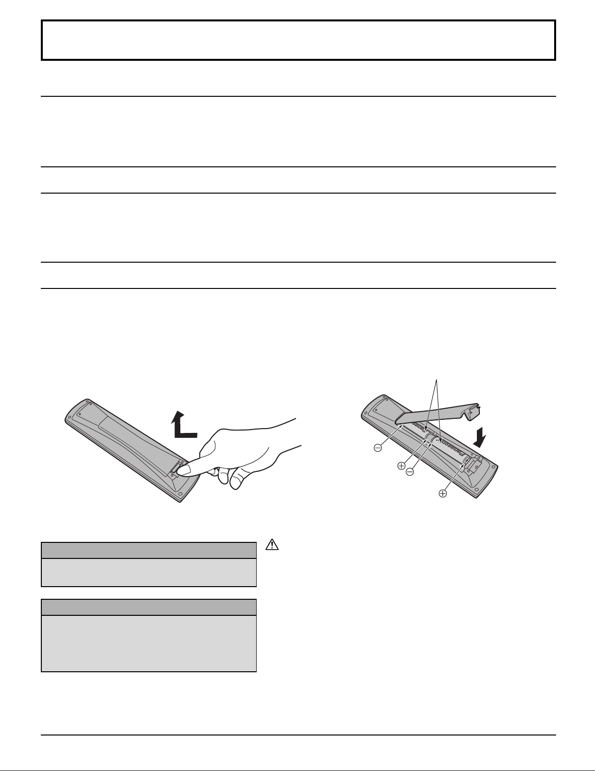
Remote Control Battery Installation
1. Open the cover.
Helpful Hints:
For frequent remote control users, replace old
batteries with alkaline batteries for longer life.
Helpful Hints:
Whenever you remove the batteries, you may
need to reset the remote control infrared
codes. We recommend that you record the code
on page 59, prior to setting up the remote control.
2. Install the batteries and replace the
cover.
Note the correct polarity (+ and -).
Two AA size
Precaution on battery use
Incorrect installation can cause battery leakage and corrosion that
will damage the remote control transmitter.
Observe the following precautions:
1. Batteries should always be replaced as a pair. Always use new
batteries when replacing the old set.
2. Do not combine a used battery with a new one.
3. Do not mix battery types (example: “Zinc Carbon” with “Alkaline”).
4. Do not attempt to charge, short-circuit, disassemble, heat or burn
used batteries.
5. Battery replacement is necessary when remote control acts
sporadically or stops operating the TV set.
9
CH
VOLCHVOL
OK
POWER
TV/VIDEO
CBL
1 2 3
4 5 6
7 809
PIP MIN
REW
PIP MAX
FF
PIP MOVE
FREEZE
TV/VCR
SPLIT SWAP
SEARCH
OPEN/CLOSE
PIP CH
DVD/VCR CH
TV
MENU
PLAY
PROG
EXIT
VCR DVD
DBS
RCVR
LIGHT
A -ANTENNA - B
SAP
AUX
A
S
P
E
C
T
M
U
T
E
R
E
C
A
L
L
B
B
E
STOP
PAUSE REC
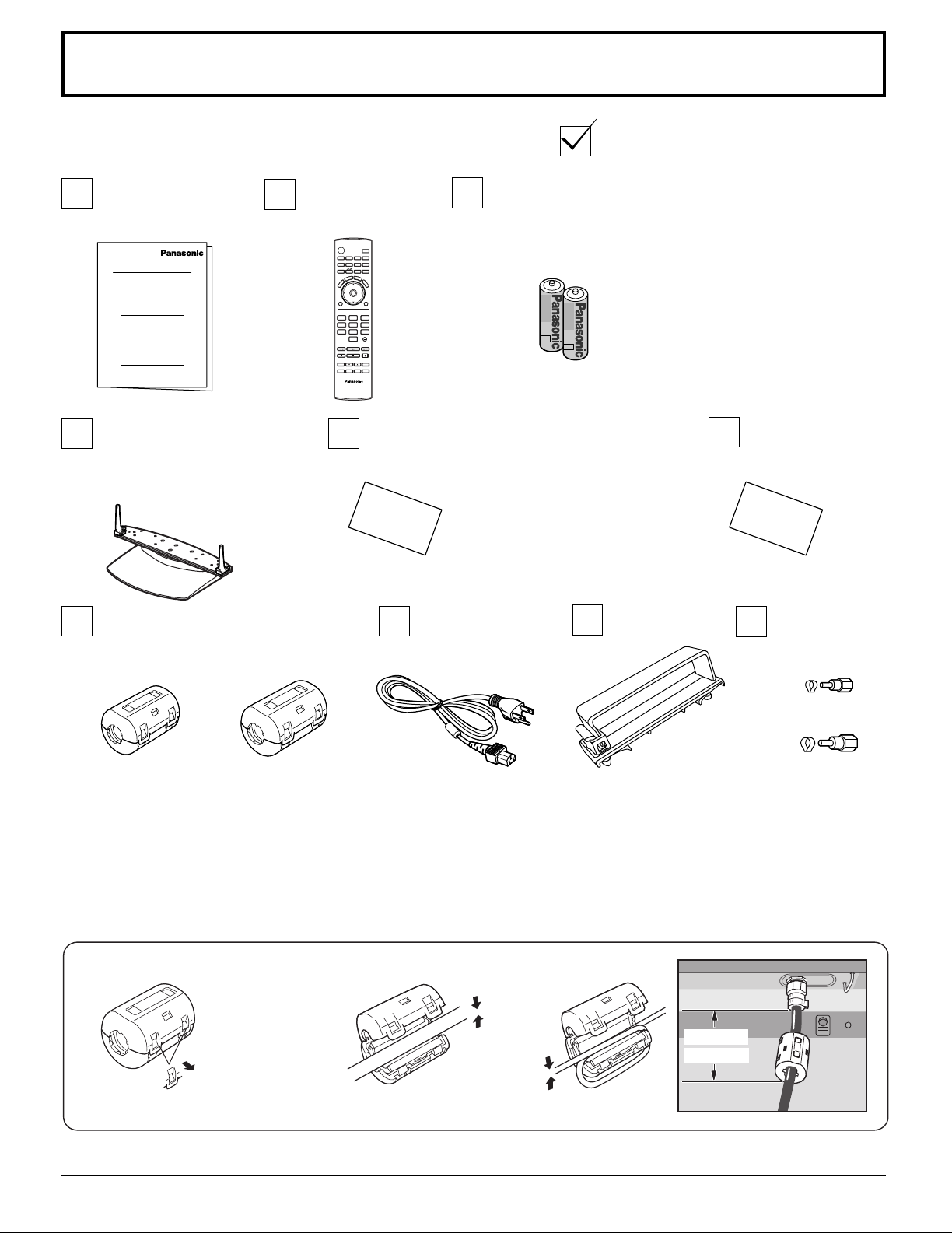
Accessories
Check that you have the Accessories and items shown
Operating
Instruction book
Pedestal
TY-ST42PX20 (TH-37PX25,
TH-42PX25)
TY-ST50PX20 (TH-50PX25)
Ferrite core
Small size × 5
Large size × 4
Remote control
EUR7627Z10
Registration card
Batteries for the remote
control
(AA Battery × 2)
Clamper (×2)AC cord
Customer care
plan card
F-Type antenna
adapter
(for 3C-2V) (×2)
(for 5C-2V) (×2)
Attaching the ferrite core
Be sure to choose the appropriate size of ferrite core (large or small) and the correct setting of the cable (winding or
passing), as indicated by each connection diagram on the following pages (13, 14, 17, 18).
1
Pull back the
tabs (in two
(Large size)
2
Put the cable
and close.
places) to open.
(Small size)
Less than
10 cm (4’’)
10
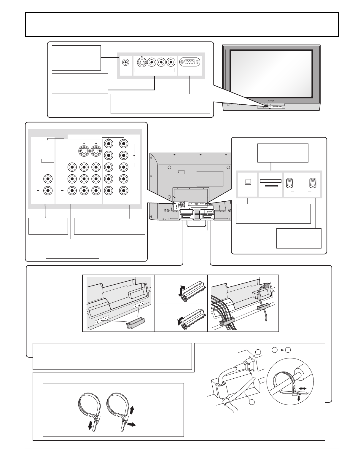
Cable Connection
PC CARD
EJECT
SD CARD
PUSH-EJECT
OKMENU TV/VIDEO VOLUME CHANNEL
S-VIDEO
PC
VIDEO
INPUT 3
L AUDIO R
HPJ
S VIDEO
PC
VIDEO
INPUT 3
L AUDIO R
HPJ
PROG OUT
COMPONENT VIDEO INPUT
S VIDEO
VIDEO
Y
P
B
L
R
P
R
12
1
2
INPUT
TO AUDIO
AMP
L
R
AUDIO IN
AV IN
VIDEO
HDmI
BAANTENNA
SERVICE ONLY
DIGITAL AUDIO
OUT
CABLE CARD
Cable In
1
2
1 2
Headphones /
Earphones jack
(see page 17)
Front AV terminals
(see page 17)
From EXTERNAL monitor terminal
on Computer (see page 18)
CABLE CARD slot
(see page 14)
HDMI terminal
(see page 15)
COMPONENT Input terminals
(see page14)
AV terminals
(see pages 16, 17)
Clamper
Fastening the power and other cables
Fastening method of other cables
Attach the clamper on the installation hole, and fasten them.
Bundle the cable with the cable fastening clamper.
Removal
Fitting
DIGITAL AUDIO OUT terminal
(see page 16)
Antenna terminals
(see pages 13,14)
Fastening band
Fastening
To tighten.
Loosening
Pull off.
Keep the knob
pressed.
Fastening method of the power cable
1. Insert the power plug into the main body.
2. Fasten with the power cable fastening band.
11
2
2
1
1
1
PROG OUT
COMPONENT VIDEO INPUT
S VIDEO
VIDEO
Y
P
B
L
R
P
R
12
1
2
INPUT
TO AUDIO
AMP
VIDEO
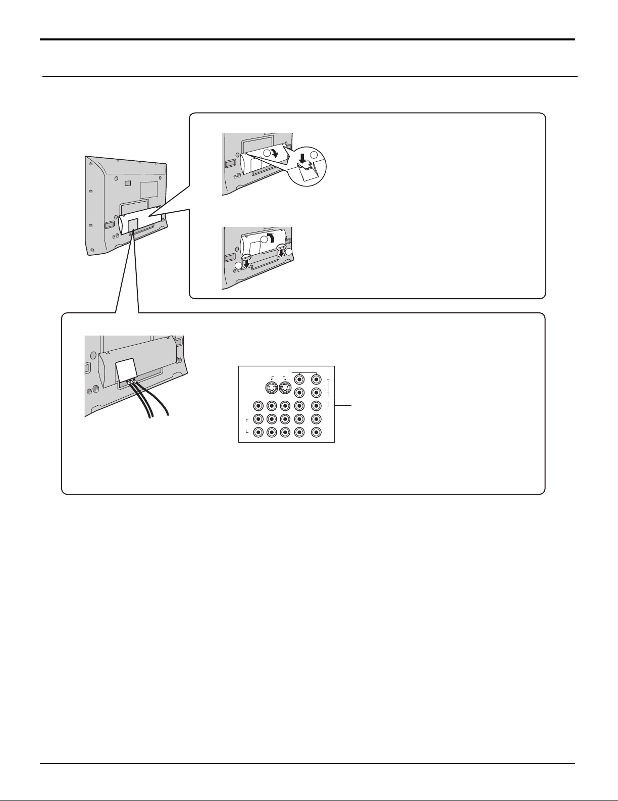
Cable Connection
Cable Cover Removal and Fitting
Removal
1. Push down hooks and pull the cover slightly
towards yourself to disengage the claws
(at 4 points).
2. Slowly pull out in the downward direction.
Fitting
1. Insert the claws (at 4 points) at the bottom
end.
2. Push the cover until hooks will be cricked.
When connecting to the rear AV input/output
terminals, connect the cables through this window.
The rear AV input/output terminals
12
(This window cannot
close completely if you
connect the cables.)
Other cables should be connected before fitting
the cable cover.
Note:
Cables and adapters are not supplied with this set unless otherwise indicated.
B ANTENNA A
Cable In
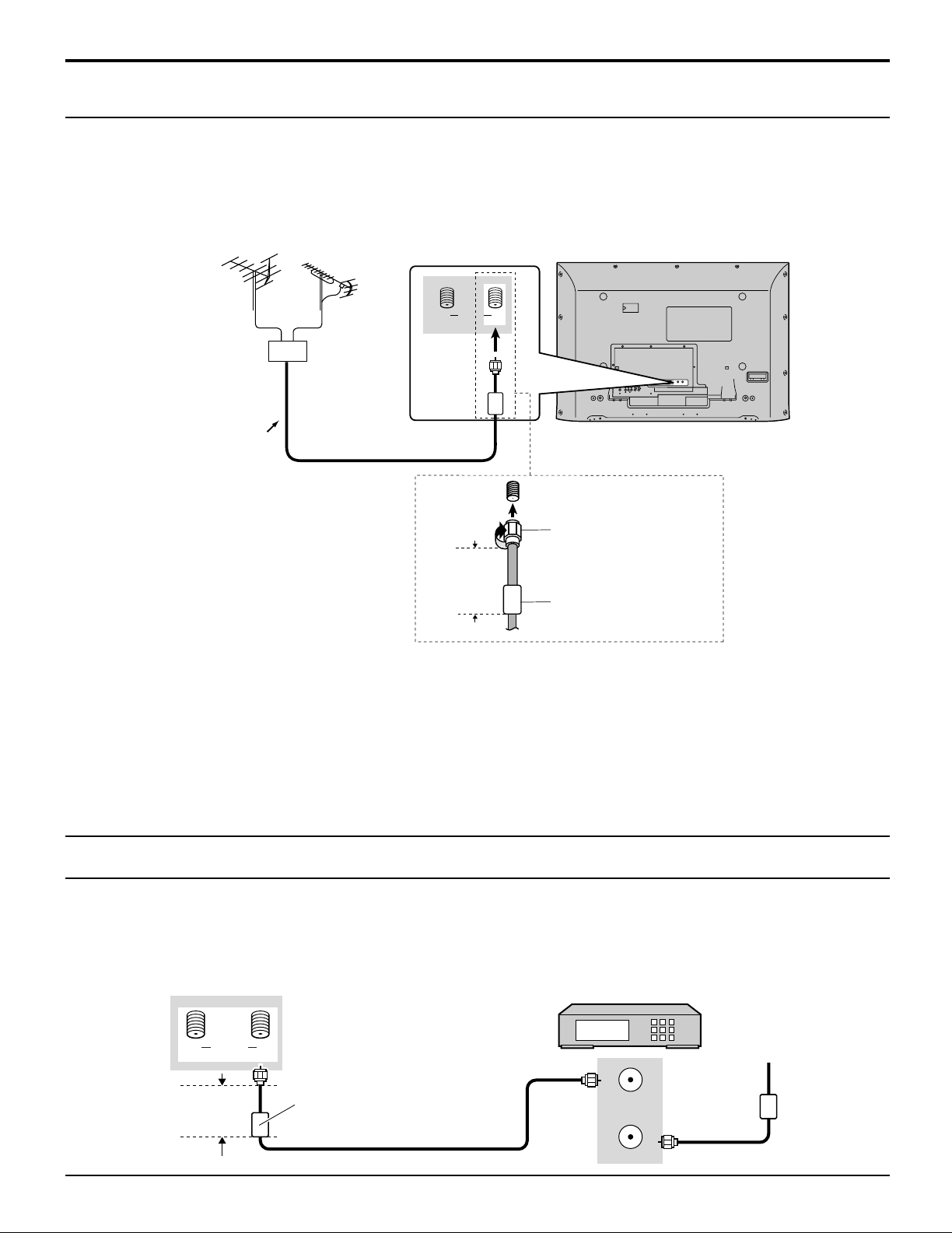
Cable Connection
ANT OUTPUT
ANT INPUT
B ANTENNA A
Cable In
Antenna Connection
• For proper reception of VHF/UHF channels, an external antenna is required. For best reception, an outdoor antenna is
recommended.
• When you enjoy the terrestrial TV programs only, connect the home antenna to ANTENNA (A).
When you enjoy both the terrestrial TV programs and the cable TV programs, connect the cable TV’s cable to ANTENNA
(A), and the terrestrial antenna cable to ANTENNA (B).
• Select the antenna mode in Input Setup (see page 22).
VHF antenna
Mixer
75 Ohm coaxial cable
UHF antenna
F-Type Antenna
Adapter (supplied)
Less than
4” (10 cm)
Ferrite core (large size)
(supplied)
Notes:
• Certain cable systems offset some channels to reduce interference or have Premium (scrambled) channels. A cable
converter box is required for proper reception. Check with your local cable company for its compatibility requirements.
• To obtain optimum quality picture and sound, an antenna, the correct cable (75 Ohm coaxial) and the correct terminating
plug are required.
• If a communal antenna system is used, you may require the correct connection cable and plug between the wall antenna
socket and your television receiver.
• Your local television service centre or dealer may be able to assist you in obtaining the correct antenna system for your
particular area and the accessories required.
• Any matters regarding antenna installation, upgrading of existing systems or accessories required, and the costs incurred,
are your responsibility.
Cable Box Connection
• When you enjoy the cable TV programs only, connect the cable TV’s cable to ANTENNA (A). When you enjoy both the
terrestrial TV programs and the cable TV programs, connect the cable TV’s cable to ANTENNA (A), and the terrestrial
antenna cable to ANTENNA (B).
• Select the antenna mode in Input Setup (see page 22).
Back of the TV
CABLE BOX
Less than
4” (10 cm)
Incoming cable
Ferrite core (large size)
(supplied)
13
Cable Connection
DIGITAL TV OUTPUT
MAIN
VIDEO
AUDIO OUTPUT
P
B
P
R
Y
R
L
PROG OUT
COMPONENT VIDEO INPUT
S VIDEO
VIDEO
Y
P
B
L
R
P
R
12
12
INPUT
VIDEO
TO AUDIO
AMP
Digital TV - Set-Top Box (DTV-STB) or DVD Connection
This TV is capable of displaying 1080i and 480p DTV signals when connected to a DTV Tuner Set-Top-Box (STB). This
TV also utilizes a progressive scan doubler, which de-interlaces the NTSC signal and progressively scans the image.
This allows you to sit close to the TV and not see the thin black horizontal lines (venetian blind effect) associated with
interlaced TV pictures.
• To view DTV programs, connect the STB to the component video input terminals (Y, PB, PR) of the TV. Component color
inputs provide luminance and separate color signal.
• Select the output of the STB to either 1080i or 480p.
• A DTV signal must be available in your area.
• Use a Panasonic DTV-STB (Digital TV-Set-Top Box) or DVD Player.
Component Video cable
Back of the TV
Set Top Box
DVD player
Audio cable
CableCARD Connection
CableCARD allows you to tune digital and high definition cable channels through the cable antenna. Consult your cable
company on the availability of CableCARD.
Procedure
1. Connect the cable antenna to ANTENNA (A).
2. Turn the TV on (see page 19).
3. Set the input mode to TV (see page 20).
4. Insert the CableCARD (as it’s upper side facing to your side) into CABLE CARD slot on the back of the TV.
Follow the messages displayed on the screen.
Back of the TV
CABLE CARD
DIGITAL AUDIO
OUT
Notes:
• If you experience keyboard or remote control function hang-up when using CableCARD, unplug the TV and plug it back
on and try the controls again. If this condition still exists, please call Panasonic Customer Call Center for further instructions.
• Do not insert a PCMCIA card into CABLE CARD slot.
14
INSERT THIS END
POD MODULE
SERVCE ONLY
BAANTENNA
Upper side of the card
Cable In
AV IN
L
R
AUDIO IN
Cable Connection
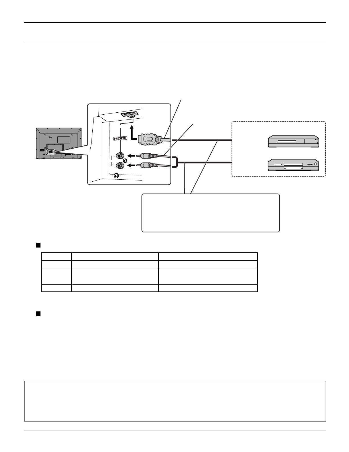
HDMI Connection
1
∗
HDMI
uncompressed standard. The HDMI terminal supports both video and audio information.
To the HDMI
a Set Top Box or DVD player with HDMI or DVI output terminal.
Input a High-bandwidth Digital Content Protection (HDCP) high-definition picture source to this HDMI terminal, so you
can display the high-definition pictures on this TV in the digital form.
(High Definition Multi media Interface) is the first all digital consumer electronics A/V interface that supports
1
∗
input terminal, you can connect an EIA/CEA-861/861B
2
∗
compliant consumer electronic device, such as
HDMI cable
Audio cable
Set Top Box
HDMI
signal out
DVD player
• If the external device has DVI output only, use a
DVI to HDMI adapter cable*3 to connect to the HDMI
terminal.
• Connect the audio cables to the AUDIO IN terminals
for HDMI.
• Select the audio setting in HDMI In (see page 29).
Compatible VIDEO Signal
1080i
480p
480i
No. of dots (H × V)
1,920 × 1,080i
720 × 480p
640 × 480p
720(1,440) × 480i
Vertical scanning frequency (Hz)
59.94/60
59.94/60
59.94/60
59.94/60
This input terminal is not intended for use with computers.
Compatible sampling freguency of AUDIO signal through HDMI (L.PCM) : 48kHz / 44.1kHz / 32 kHz
Notes:
• This HDMI connector is Type A.
• If you connect an equipment without a digital output terminal, connect to the COMPONENT VIDEO, S VIDEO or
VIDEO input terminal on the TV so you can enjoy an analog signal.
• The DIGITAL IN terminal can only be used with 1080i, 480i or 480p picture signals. Set the Digital Set -Top -Box
DIGITAL OUT terminal Output setting to 1080i, 480i or 480p. For detailed information, refer to the Digital Set -Top Box instruction manual. If you cannot display the picture because your Digital Set -Top -Box does not have a
DIGITAL OUT terminal Output setting, use the component Video Input (or the S Video Input or Video Input). In this
case the picture will be displayed as an analog signal.
1. HDMI, the HDMI logo and High-Definition Multimedia Interface are trademarks or registered trademarks of HDMI
∗
Licensing LLC.
2. EIA/CEA-861/861B profiles compliance covers profiles for transmission of uncompressed digital video including
∗
high bandwidth digital content protection.
3. HDMI-DVI conversion cable (TY-SCHO3DH): available on Panasonic Website (www.panasonic.com). Consult your
∗
consumer electronics dealer for availability details.
15
Cable Connection
PROG OUT
COMPONENT VIDEO INPUT
S VIDEO
VIDEO
Y
P
B
L
R
P
R
12
12
INPUT
VIDEO
TO AUDIO
AMP
OUTPUT
AUDIO
VIDEO
S VIDEO
RL
PROG OUT
COMPONENT VIDEO INPUT
S VIDEO
VIDEO
Y
P
B
L
R
P
R
12
12
INPUT
VIDEO
TO AUDIO
AMP
AUDIO INPUT
OPTICAL IN
R
L
DIGITAL AUDIO
OUT
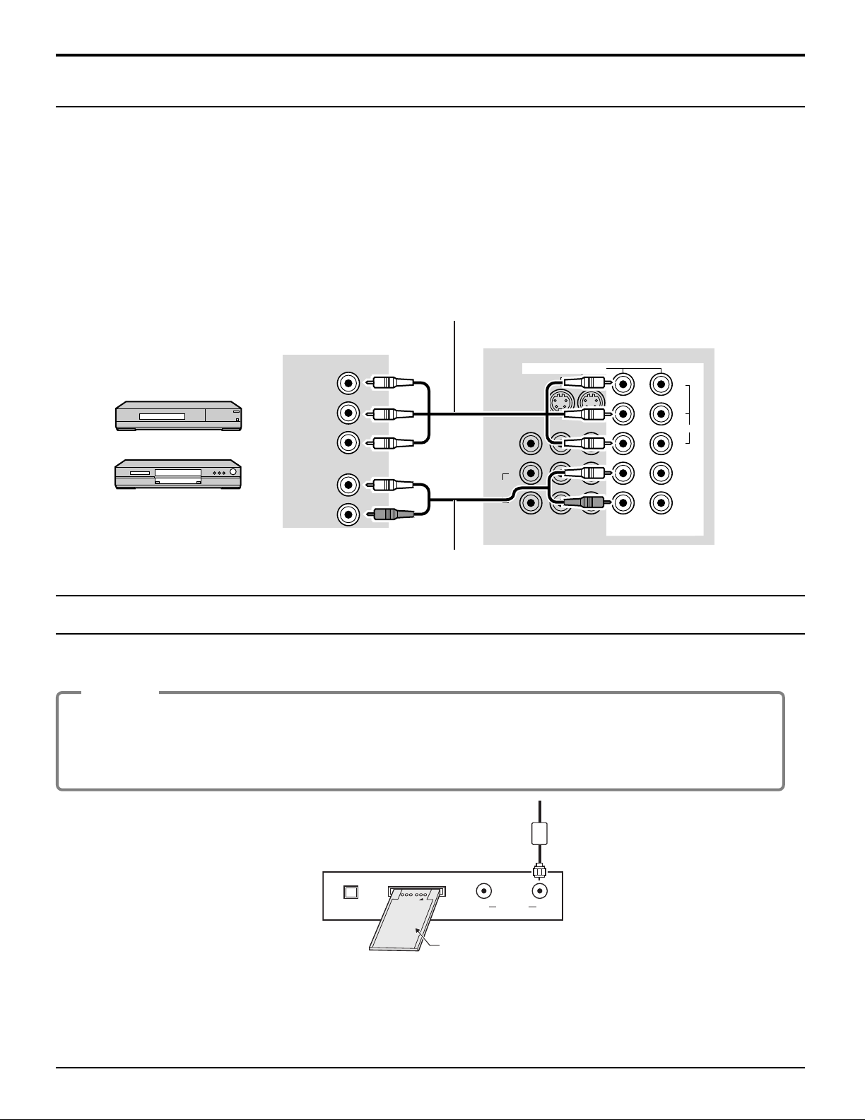
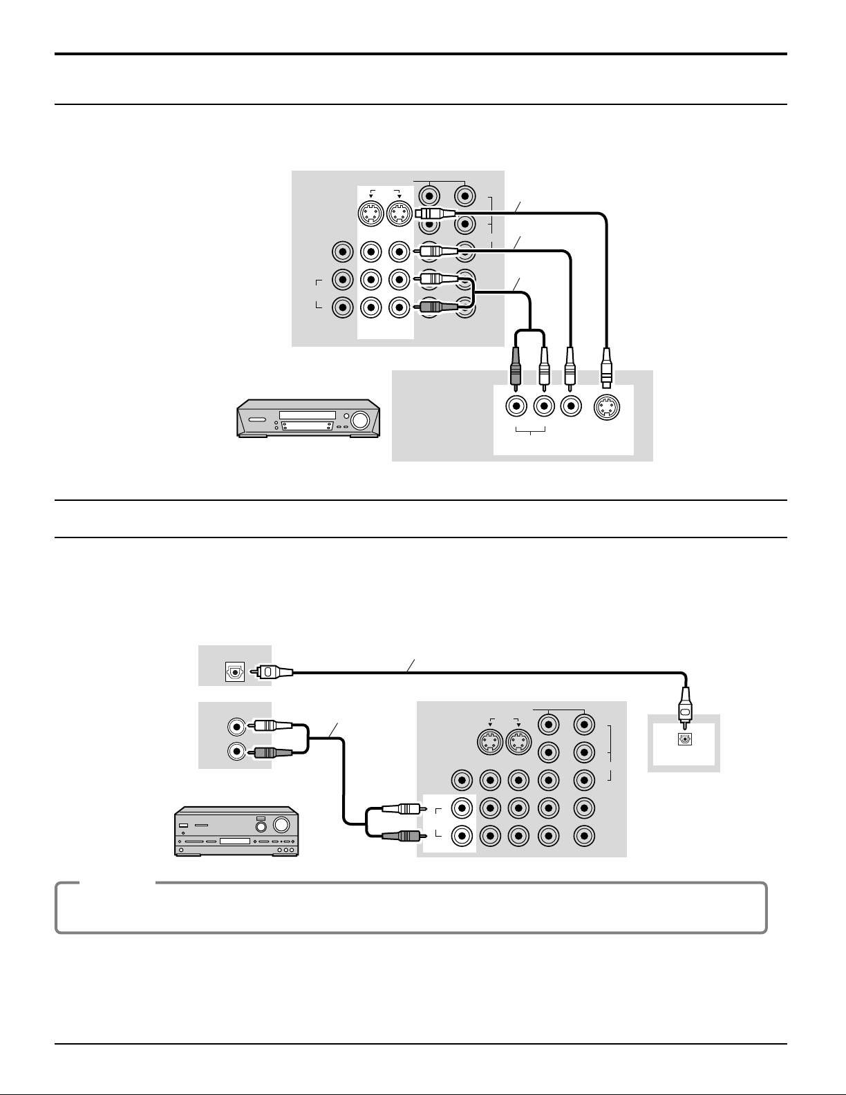
VCR Connection
Back of the TV
S-Video cable
Video cable
Audio
cable
VCR
Amplifier Connection (TO AUDIO AMP)
For a full Home Theater sound experience, an external Dolby Digital∗ decoder and a multichannel amplifier must be
connected to the DIGITAL AUDIO OUT terminal on the TV.
Dolby Digital 5.1 channel surround sound delivers digital-quality sound. Dolby Digital provides five discrete full-bandwidth
∗
channels for front left, front right, center, surround left and surround right, plus a LFE (Low Frequency Effect) subwoofer
channel.
Optical digital audio cable
or
Audio cable
Amplifier
Procedure
1. Select Speakers “Off” in Audio menu (see page 29).
2. Adjust the amplifier volume to the desired level.
Notes:
• External speakers cannot be connected directly to TO AUDIO AMP terminals.
• When ATSC channel is selected, the output from the DIGITAL AUDIO OUT jack will be Dolby Digital. When NTSC
channel is selected, the output will be PCM.
Back of the TV
16
PROG OUT
COMPONENT VIDEO INPUT
S VIDEO
VIDEO
Y
P
B
L
R
P
R
12
12
INPUT
VIDEO
TO AUDIO
AMP
VIDEO
AUDIO
R
L
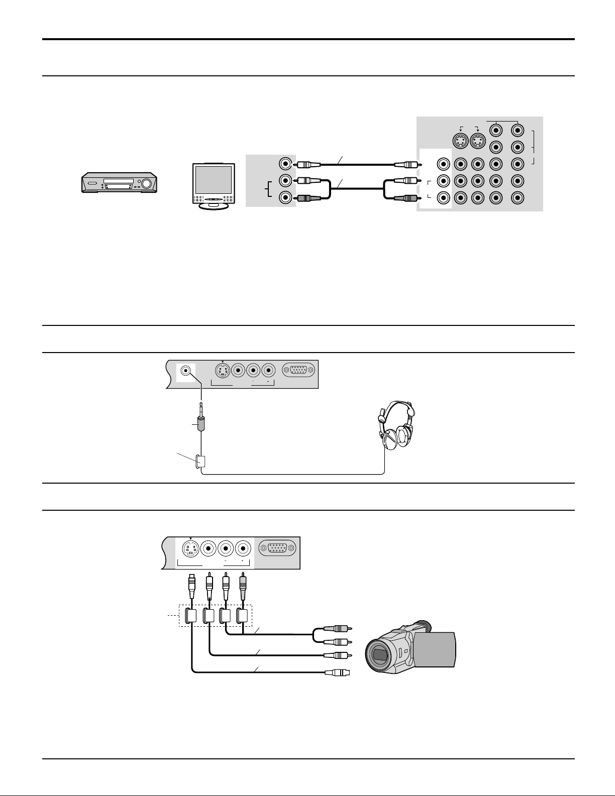
Program Out Connection (PROG OUT)
S VIDEO
PC
VIDEO
INPUT 3
L AUDIO R
HPJ
S VIDEO
PC
VIDEO
INPUT 3
L AUDIO R
See optional equipment manual for further instructions for recording and monitoring.
Cable Connection
Back of the TV
VCR MONITOR
Video cable
Audio cable
OR
Notes:
• When a device (STB, DVD, etc.) is connected to the HDMI terminal (see page 15), no video or audio is output due to
license restrictions.
• Program Out signal may not be available when COMPONENT input (see page 20) is selected for the Main picture during
PIP or SPLIT operation (see pages 52, 54).
• When receiving digital channel signals, all digital formats are down-converted to composite NTSC video to be output
through Program Out terminals.
• Some programs contain Macrovision signal to prevent VCR recording.
Connecting Headphones / Earphones
M3 plug
Headphones /
Ferrite core (small size)
(supplied)
Earphones
(not supplied)
Connecting to the front AV terminals
Push to open the front panel and connect equipment to front Audio/Video input terminals.
Ferrite core (small size)
(supplied)
Audio cable
Video cable
S-Video cable
A second VCR, video disc player, video game equipment and DSS equipment can also be connected to the video input
terminals. See the optional equipment manual for details.
Note:
The S-VIDEO connection provides higher quality picture. It overrides other VIDEO connections. Use INPUT 3, AUDIO
L and R with S-VIDEO connection.
CAMCORDER
17
Cable Connection
S VIDEO
PC
VIDEO
INPUT 3
L AUDIO R
1
67839
45
10
1514131211
2
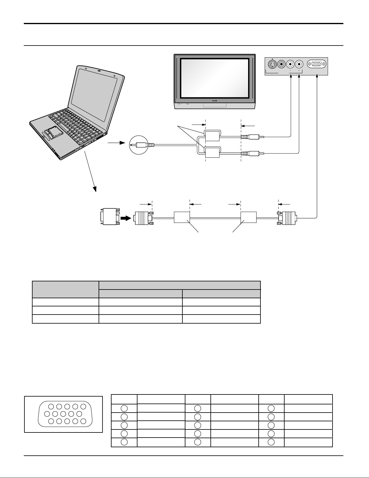
PC Input Terminals Connection
COMPUTER
Ferrite core (small size)
(supplied)
Less than
4" (10 cm)
Audio
Stereo plug
Connect a cable which matches
the audio output terminal on the computer.
Conversion adapter
(if necessary)
Less than
4" (10 cm)
Less than
4" (10 cm)
RGB
PC cable
D-sub 15p
Ferrite core (large size)
(supplied)
Notes:
(1) Computer signals which can be input are those with a horizontal scanning frequency of 15 to 110 kHz and vertical
scanning frequency of 48 to 120 Hz. (However, the image will not be displayed properly if the signals exceed 1,200
lines.)
(2) The maximum resolution:
Aspect
Model
TH-37PX25
TH-42PX25
TH-50PX25
4:3
768 × 720
768 × 768
1,024 × 768
16:9
1,024 × 720
1,024 × 768
1,366 × 768
If the display resolution exceeds these maximums, it may not be possible to show fine detail with sufficient clarity.
(3) Some PC models cannot be connected to the set.
(4) There is no need to use an adapter for computers with DOS/V compatible D-sub 15P terminal.
(5) The computer shown in the illustration is for example purposes only.
(6) Additional equipment and cables shown are not supplied with this set.
(7) Do not set the horizontal and vertical scanning frequencies for PC signals which are above or below the specified
frequency range.
Signal Names for D-sub 15P Connector
Signal Name
R
G
B
NC (not connected)
GND (Ground)
Pin No.
6
7
8
9
10
Signal Name
GND (Ground)
GND (Ground)
GND (Ground)
NC (not connected)
GND (Ground)
Pin No.
11
12
13
14
15
Signal Name
NC (not connected)
NC
HD/SYNC
VD
NC
18
Pin Layout for PC Input
Terminal
Pin No.
1
2
3
4
5
POWER
POWER
Power ON / OFF
TV VCR DVD
DBS
RCVR
CBL
LIGHT
TV/VIDEO
A -ANTENNA - B
SAP
AUX
A
S
P
E
C
T
B
B
E
POWER
PC CARD
EJECT
SD CARD
PUSH-EJECT
HPJ
ACTIONINPUT VOLUME CHANNEL
S-VIDEO
PC
VIDEO
INPUT 3
L AUDIO R
HPJ
PC CARD
EJECT
SD CARD
PUSH-EJECT
MENU OK TV/VIDEO VOLUME CHANNEL
S VIDEO
POWER
PC
VIDEO
INPUT 3
L AUDIO R
Remote control senser
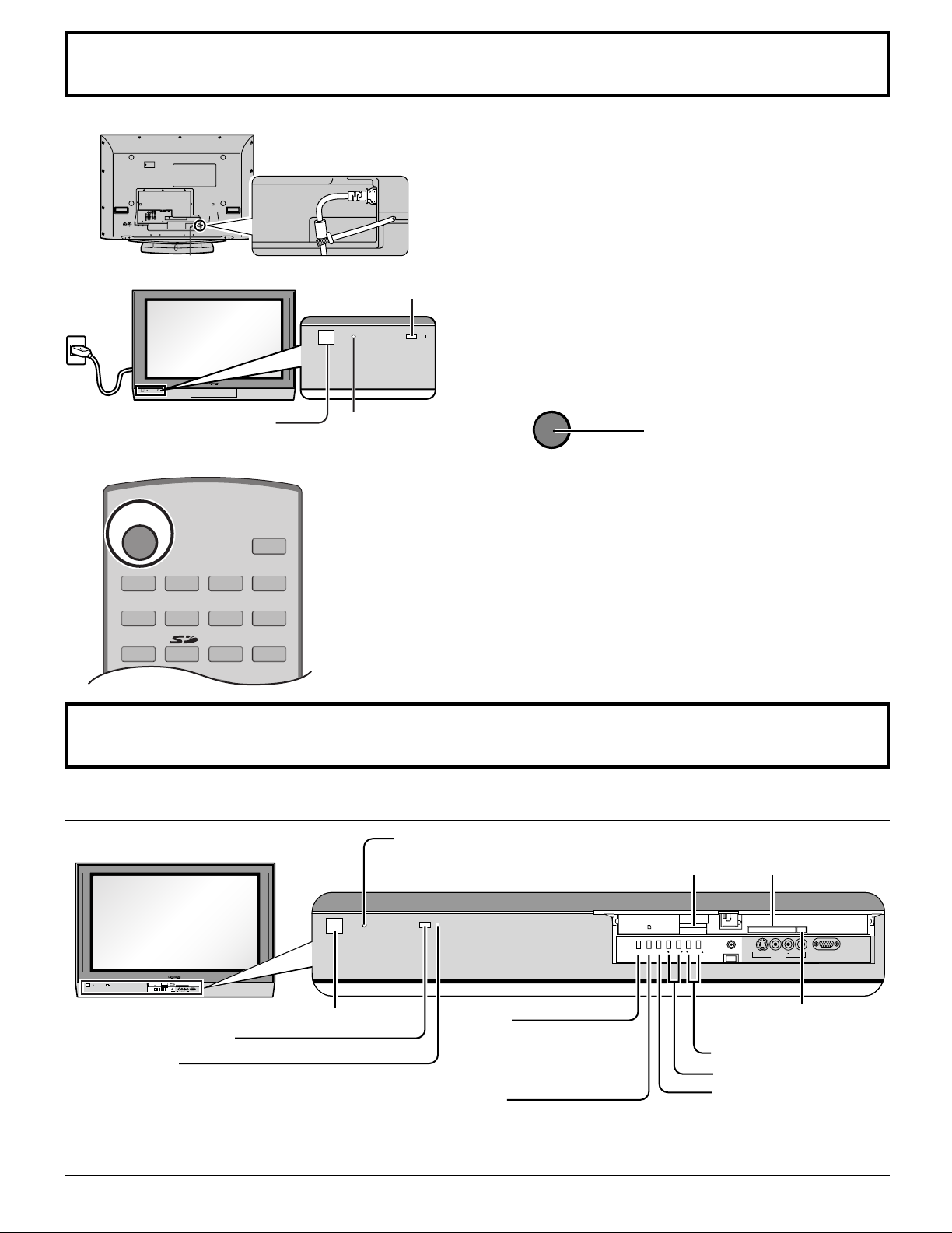
Connect the AC cord plug to the Plasma TV.
1
• Fix the power cord plug securely with the clamper
(see page 11).
Connect the plug to the wall outlet.
2
POWER button
Power indicater
Power on: Red
Power off: No Light
Location of Controls
The Main Unit
Power indicator
Power on : Red
Power off : No Light
3
Press to turn the TV on or off.
Note:
The TV will still consume some power as long as the
power cord is still inserted into the wall outlet.
SD CARD slot PC CARD slot
Remote control sensor
POWER button
C.A.T.S. sensor
Plasma C.A.T.S. (Contrast Automatic Tracking System)
automatically senses the ambient light conditions and
adjusts the brightness and gradation accordingly, to
optimise contrast.
Effective when Pic Mode is set to Auto (see page 26).
MENU
Display Main Menu or return
one step backward in menus
(see pages 24, 57)
.
OK
Choose menu and submenu
entry.
PC CARD
EJECT button
Channel selectors
Volume adjusters
TV/VIDEO
Change the input mode.
19
TV
POWER
MENU
R-TUNE
PIP MIN
REW
PIP MAX
FF
PLAY
PROG
EXIT
VCR DVD
DBS
RCVR
CBL
LIGHT
TV/VIDEO
A -ANTENNA - B
SAP
1 2 3
4 5 6
7 8
0
9
AUX
A
S
P
E
C
T
M
U
T
E
R
E
C
A
L
L
B
B
E
STOP
PAUSE
FREEZE
TV/VCR
PIP SPLIT MOVE SWAP
SEARCH
OPEN/CLOSE
PIP CH
DVD/VCR CH
REC
CH
VOL
CH
VOL
OK
COMPONENT 2
HDMI
TV
COMPONENT 1
VIDEO 3PC VIDEO 1VIDEO 2
Location of Controls
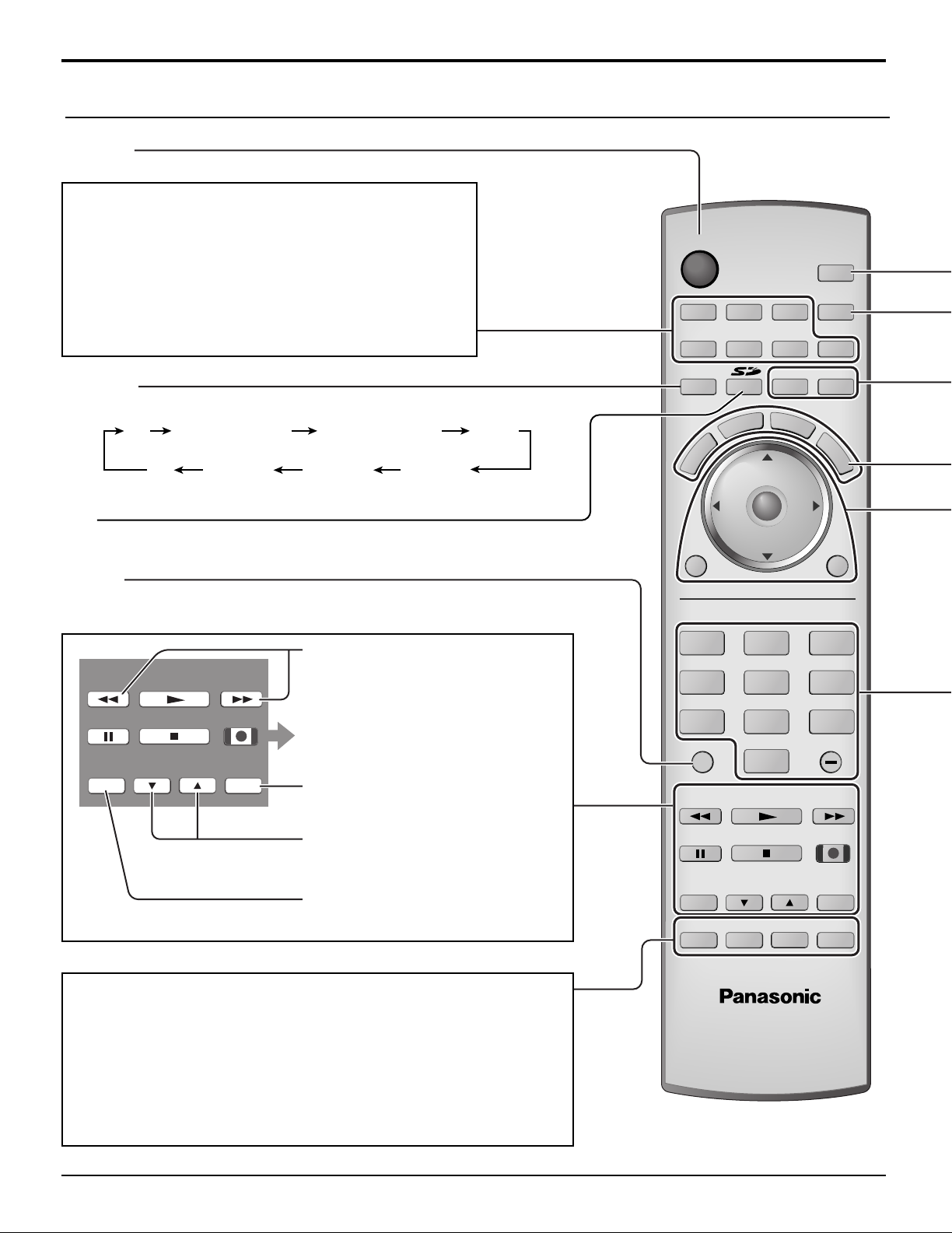
The Illuminated Remote Control
POWER
Turn the TV ON or OFF.
Mode Selection buttons (see page 59)
TV: TV
VCR: VCR
DVD: DVD
DBS: Digital Broadcasting Satellite
RCVR:Receiver/Amplifier
CBL: Cable TV
AUX: Aux
TV/VIDEO
Change the input mode.
SD
Access Photo Viewer (see page 48).
R-TUNE
Switch to previously viewed channel and input modes.
PIP MIN, PIP MAX
PIP MIN
REW
PAUSE
FREEZE
TV/VCR
PLAY
STOP
PIP CH
DVD/VCR CH
PIP MAX
FF
REC
SEARCH
OPEN/CLOSE
Change the size of PIP frame (see
page 52).
Operation of other Device (see
pages 63, 64)
SEARCH
Display search frames during PIP or
SPLIT operation (see pages 53, 55).
PIP CH
Select the channel during PIP or
SPLIT operation (see pages 52, 54).
FREEZE
Freeze the picture (see pages 53, 55).
PIP
PIP (Picture in Picture) Operation (see page 52)
SPLIT
Split Screen (see page 54)
MOVE
Move PIP frame (see page 53).
SWAP
Swap pictures in PIP or SPLIT operation (see page 52, 54).
20

Stereo SAP Mono
A: 15-1
KPBS - HD
Add FAV
TV-G 1080i
VIVID HDMI
12:30 pm
30
CC
SAP
Antenna designation,
Channel and program #
and Station identifier Rating Clock
Program Aspect
Picture mode setting
PIP/SPLIT CH
number or
Input information
Closed Caption
SAP indication
Time remaining
in Sleep Timer
Press OK button to add or delete the channel
in the Favorite channel list (see page 30).
Location of Controls
SAP
• Digital channel
Select the audio track (if available).
Audio Track 1 of 1 (English)
• Analog channel
Cycle through different audio modes.
ex. If receiving Stereo, SAP and Mono or receiving Stereo and Mono only:
LIGHT
Light the remote control buttons. The selected button blinks when lit.
A -ANTENNA - B
Switch to (A or B) RF antenna input.
MUTE
Mute the sound. Press again to cancel the mute.
ASPECT
Change the screen aspect (see page 56).
BBE
Turn BBE VIVA 3D OFF or ON (see page 29).
RECALL
Display or remove the channel banner.
CH: Change to the next channel up.
: Move cursor upward during menu mode.
VOL : Reduces volume.
: Move cursor to the left
CH
during menu mode.
VOL
OK
VOL
MENU
Display Main Menu or return
MENU EXIT
CH
one step backward in
menus (see pages 24, 57).
CH: Change to the next channel down.
: Move cursor downward during menu mode.
Direct program number selection buttons
PROG -: When tuning digital channel, press the button to enter the minor number in a compound
channel number.
• To enter the channel number
ex. CH 15-1: [1] [5] [-] [1] [OK]
Choose menu and submenu entry.
VOL : Increase volume.
: Move cursor to the right during
menu mode.
EXIT
Exit menus.
21
First Time Setup
TV
POWER
VCR DVD
DBS
RCVR
CBL
LIGHT
TV/VIDEO
A -ANTENNA - B
SAP
1 2 3
AUX
A
S
P
E
C
T
M
U
T
E
R
E
C
A
L
L
B
B
E
CH
VOL
CH
VOL
OK
MENU EXIT
CH
VOL
CH
VOL
OK
CH
VOL
CH
VOL
OK
CH
VOL
CH
VOL
OK
CH
VOL
CH
VOL
OK
MENU
EXIT
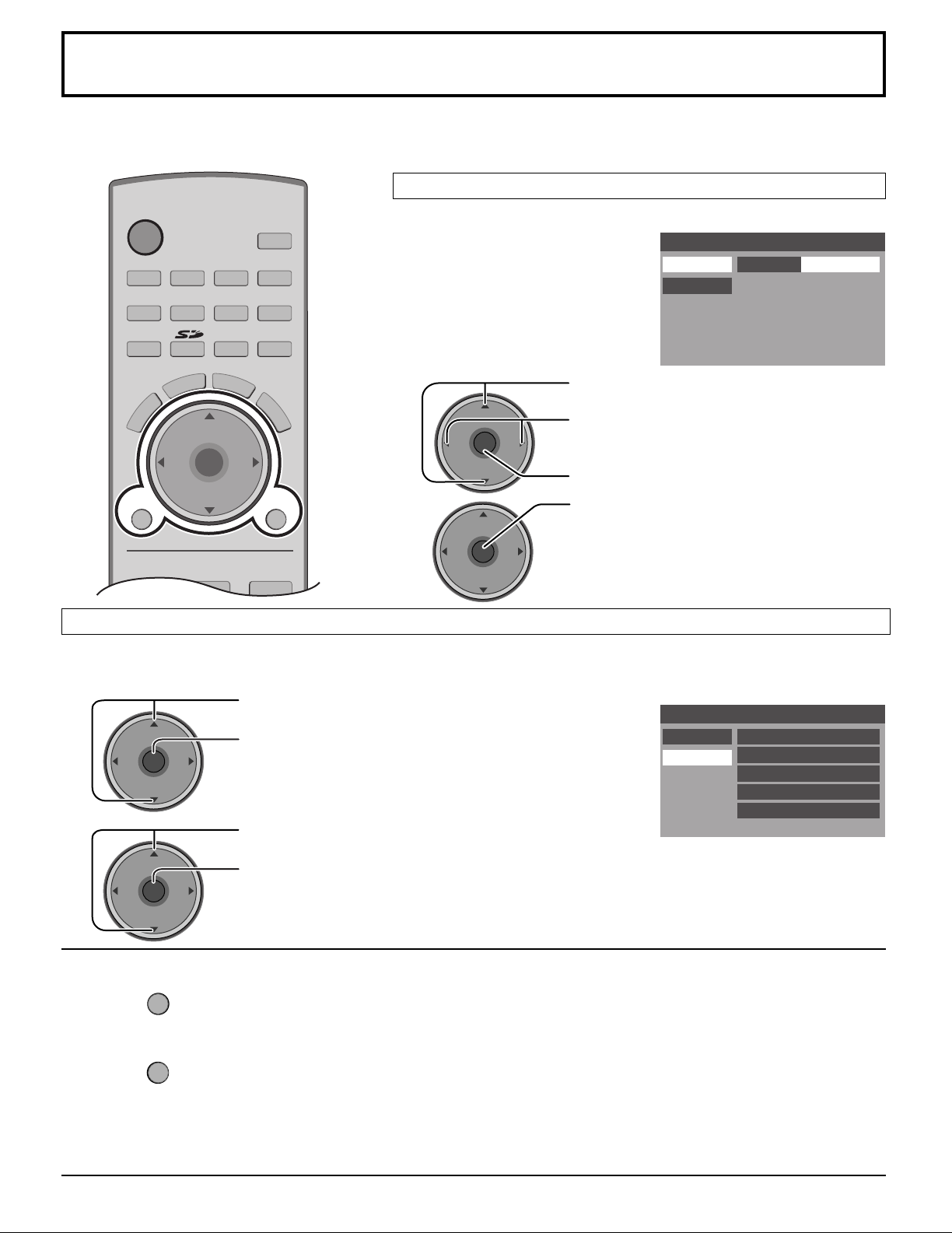
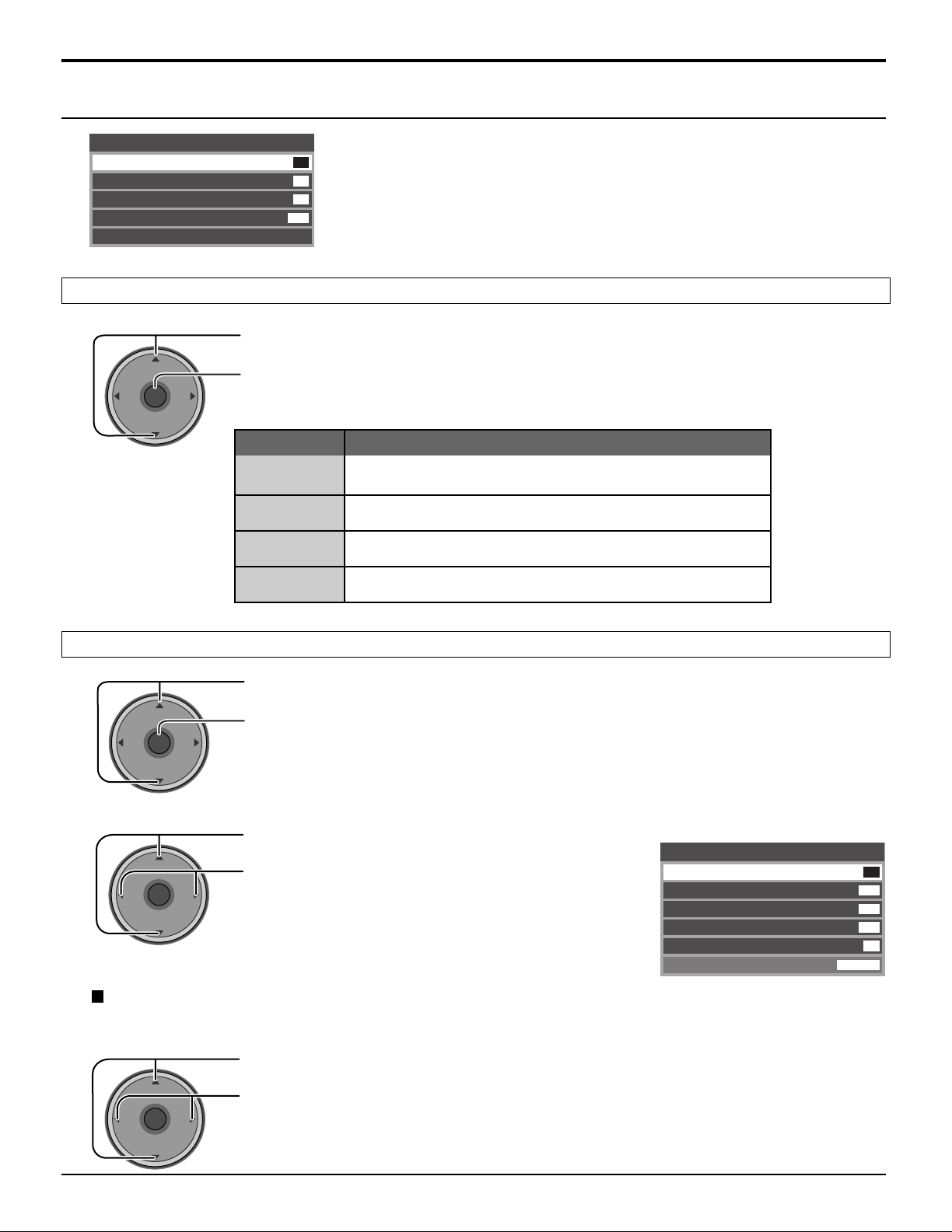
For your convenience, First Time Setup menu will be displayed on screen when the set is turned on for the first time. If
needed, follow the menus and procedures displayed on-screen for setting up the features.
You can also make the settings in Setup menu (see pages 36, 37).
Input Setup
Select the configuration of RF input depending on the signal source.
First Time Setup
Input Setup
Auto Scan
Setting
Cable/Antenna
1
2
Auto Scan
This feature allows you to selectively auto scan channels.
You can scan All, Analog only channels or Analog & Digital channels.
Press to select Auto Scan.
Press to enter the sub-menu field.
Press to select the sub-menu.
Press to start Auto Scan.
After Auto Scan is completed, the TV tunes to the first channel found during Auto Scan.
1
2
Press to select Input Setup.
Press to select Cable only, Cable/Antenna or
Antenna only.
Press to enter your selection.
Press to start the Auto Scan.
All available channels with a signal will be
programmed into memory.
First Time Setup
Input Setup Scan All
Auto Scan
Antenna (A) Analog
Antenna (A) Analog & Digital
Antenna (B) Analog
Antenna (B) Analog & Digital
To return to the previous menu
Press
To exit the menu screen
Press
Notes:
• If the EXIT button is pressed at anytime during Auto Scan, Auto Scan will be cancelled and the TV will return to the First
Time Setup menu.
• If a CableCARD is present during the First Time Setup and Antenna (A) is set to cable, Antenna (A) will not be scanned
due to the CableCARD providing the channel map.
22
.
.
Watching TV programs
MENU
R-TUNE
PIP MIN
REW
PIP MAX
FF
PLAY
PROG
EXIT
VCR DVD
DBS
RCVR
LIGHT
A -ANTENNA - B
SAP
1 2 3
4 5 6
7 8
0
9
AUX
A
S
P
E
C
T
M
U
T
E
R
E
C
A
L
L
B
B
E
STOP
PAUSE
FREEZE
TV/VCR
PIP SPLIT MOVE
SWAP
SEARCH
OPEN/CLOSE
PIP CH
DVD/VCR CH
REC
CH
VOL
CH
VOL
OK
POWER
TV/VIDEO
TV
CBL
POWER
TV
CH
VOL
CH
VOL
OK
CH
VOL
CH
VOL
OK
CH
VOL
CH
VOL
OK
POWER
CBL
VHF and UHF
1
Press to operate the TV set with the remote
control.
2
3
4
Press to turn the TV on.
Press to select desired channel.
Select the desired volume level.
Notes:
• The channel number and volume level remain the same even after the
TV is turned off.
• Power consumption and howling sound can be reduced if the volume
level is lowered.
Cable TV
Make sure that registration with cable TV provider and connection of equipment
are completed.
1
2
3
Select the TV channel 3 or 4.
Press to operate the cable box with the
remote control.
Press to turn the cable box on.
• Point the remote control towards the
cable box.
Notes:
• The remote control code number is set
for Panasonic products.
• To operate other manufacturer's
product (see pages 59 - 64).
23
Menu Navigation
MENU
CH
VOL
CH
VOL
OK
CH
VOL
CH
VOL
OK
CH
VOL
CH
VOL
OK
TV
POWER
R-TUNE
PIP MIN
REW
PIP MAX
FF
PLAY
PROG
VCR DVD
DBS
RCVR
CBL
LIGHT
TV/VIDEO
A -ANTENNA - B
SAP
1 2 3
4 5 6
7 8
0
9
AUX
A
S
P
E
C
T
M
U
T
E
R
E
C
A
L
L
B
B
E
STOP
PAUSE
FREEZE
TV/VCR
PIP SPLIT MOVE
SWAP
SEARCH
OPEN/CLOSE
PIP CH
DVD/VCR CH
REC
CH
VOL
CH
VOL
OK
MENU EXIT
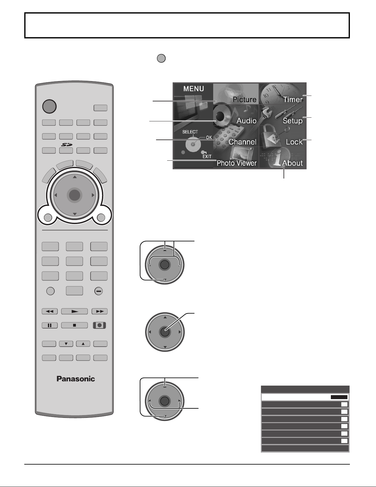
1
Press to display the Main menu.
Timer
Picture
(see page 33)
(see page 26)
Audio
(see page 28)
Channel
(see page 30)
Setup
(see page 36)
Lock
(see page 42)
Photo V iewer
(see page 46)
About
The About screen displays
assorted information about
the TV. Please have this
information when calling
Customer Care Center.
2
Press to select the menu.
4
3
Press to enter the sub-menu field.
Press to select
the sub-menu.
Press to adjust
the sub-menu.
ex. Picture menu
Picture
Pic Mode
Color
Tint
Brightness
Picture
Sharpness
Normal
Other Adjust
Vivid
31
31
26
63
50
No
24
CH
VOL
CH
VOL
OK
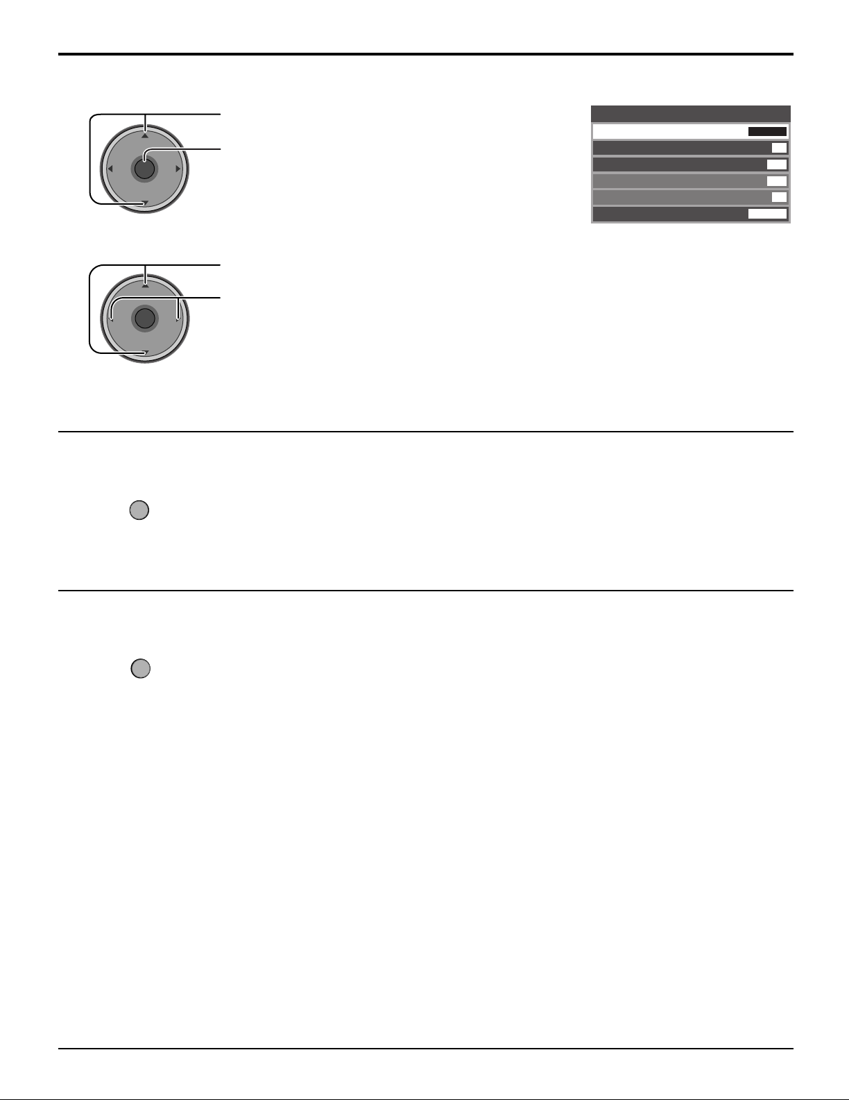
[ To select Other Adjust sub-menu]
MENU
EXIT
CH
VOL
CH
VOL
OK
1
Press to select Other Adjust.
Press to display the sub-menu.
Menu Navigation
Other Adjust
Color
Temp
Natural
Color
Video NR
3D Y/C Filter
Color Matrix
Freeze
Cool
Split
On
Off
Off
HD
2
Press to select the sub-menu.
Press to select or activate the sub-menu.
To return to the previous screen
Press to return.
To exit menus
Press to return to normal picture.
25
CH
VOL
CH
VOL
OK
CH
VOL
CH
VOL
OK
CH
VOL
CH
VOL
OK
Menu Navigation
CH
VOL
CH
VOL
OK
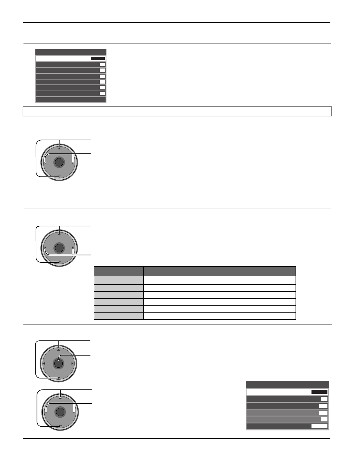
Picture
Picture
Pic Mode
Color
Tint
Brightness
Picture
Sharpness
Normal
Other Adjust
Pic Mode
Lets you choose the pre-set picture modes that best suits the program you are viewing. This feature also affects Color
Temp setting (see page 27).
Note:
Each mode has its own picture settings (Color, Tint, Brightness, Picture and Sharpness).
Vivid
31
31
26
63
50
No
Press to select Pic Mode.
Press to select the picture mode.
Vivid (default):
•
Standard : Recommended for normal viewing conditions with subdued room lighting.
•
Cinema : For watching movies in a darkened room. It provides a soft, film-like picture.
•
Auto : Automatically senses the ambient light conditions and adjusts the brightness
•
Provides enhanced picture contrast and sharpness for viewing in a well-lit room.
and gradation accordingly, to optimise contrast.
Color / Tint / Brightness / Picture / Sharpness / Normal
Press to select the sub-menu.
Press to adjust the sub-menu.
Item
Color
Tint
Brightness
Picture
Sharpness
Normal
Adjusts desired color intensity.
Adjusts natural flesh tones.
Adjusts dark areas of picture.
Adjusts white areas of picture.
Adjusts clarity of outline detail.
Resets all picture adjustments to factory default settings.
Other Adjust
1
Press to select Other Adjust.
Press to display the sub-menu.
Explanations
2
26
Press to select the sub-menu.
Press to select or activate the sub-menu.
Other Adjust
Color
Temp
Color
Natural
Video NR
3D Y/C Filter
Color Matrix
Freeze
Cool
On
Off
Off
HD
Split
CH
VOL
CH
VOL
OK
CH
VOL
CH
VOL
OK
CH
VOL
CH
VOL
OK
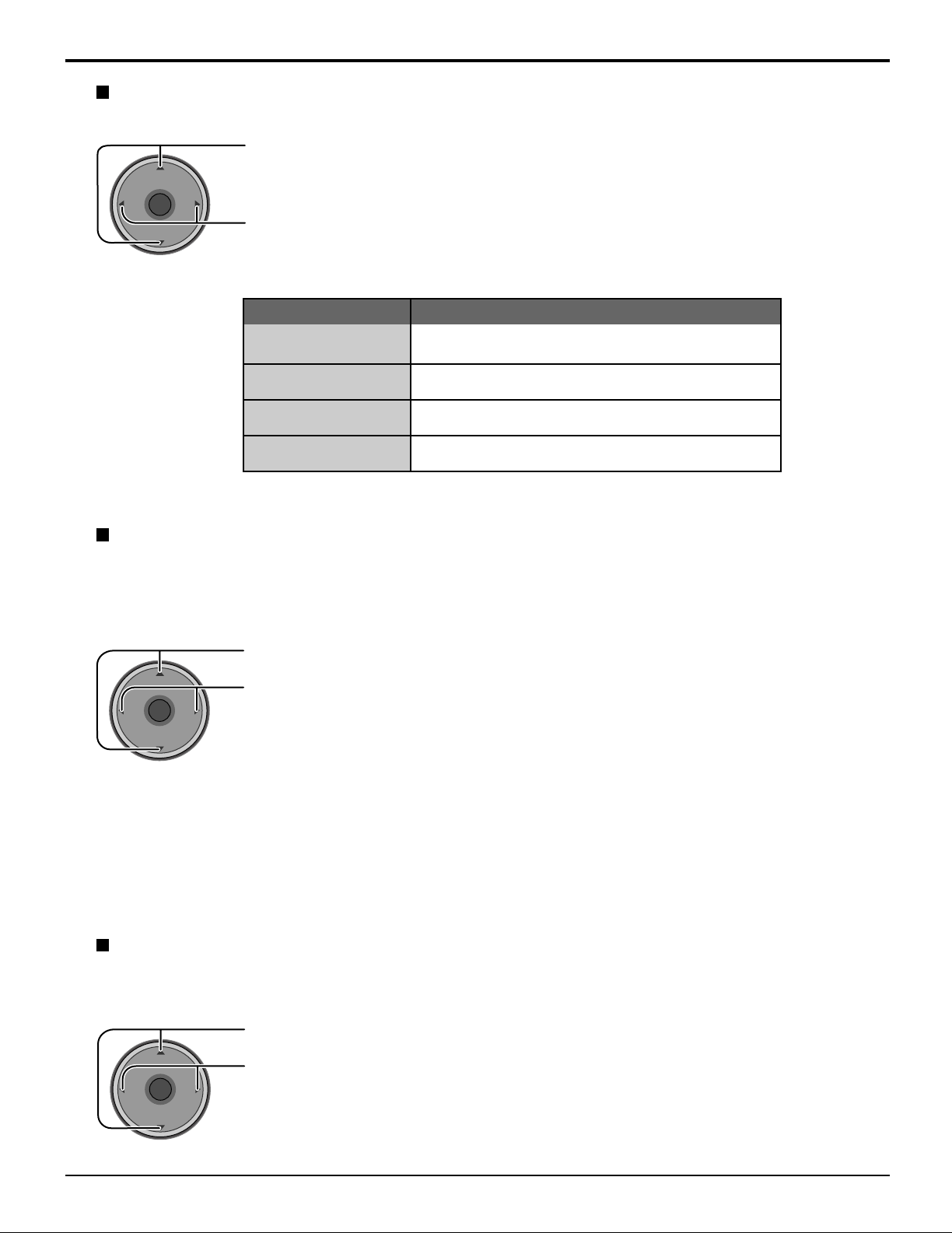
Color Temp (temperature) / Natural Color / Video NR / 3D Y/C Filter
Press to select the sub-menu.
Press to adjust or activate the sub-menu.
Menu Navigation
Item
Color Temp
(temperature)
Natural Color
Video NR
3D Y/C Filter
To increase or decrease Warm (red) and Cool
colors to suit personal preferences.
To increase the color reproduction range with natural
color gradation and highly delicate hues.
Reduces noise in the channel, commonly called
snow. Remains off when receiving a strong signal.
Minimizes noise and cross color in the picture.
Explanations
(blue)
Color Matrix
Displays 480p input signals in a natural color from digital equipment adapters connected to COMPONENT VIDEO
INPUT (Y, PB, PR) terminals.
Select HD or SD to automatically adjust color parameters for HD (high definition) or SD (standard definition).
Press to select Color Matrix.
Press to select SD or HD.
SD : When the input signal is a normal TV system (NTSC).
•
HD : When the input signal is a High-Definition system (ATSC).
•
Notes:
• This feature is available only with 480p signal and not available with regular TV (NTSC) program.
• When viewing a non-standard DTV signal format, you can change color parameters manually for the best picture quality.
Freeze
This feature is used to freeze main picture and display it in a PIP or SPLIT frame, when the FREEZE button on the
remote control is pressed. Press FREEZE again to delete frame (see pages 53, 55).
Press to select Freeze.
Press to select Split or PIP.
27
CH
VOL
CH
VOL
OK
CH
VOL
CH
VOL
OK
CH
VOL
CH
VOL
OK
Menu Navigation
CH
VOL
CH
VOL
OK
Audio
Audio
Bass
Treble
Balance
Normal
Other Adjust
Bass / Treble / Balance / Normal
Press to select the sub-menu.
Press to adjust or activate the sub-menu.
7
7
31
Set
Other Adjust
1
2
Item
Bass
Treble
Balance
Normal
Increase or decrease the bass response.
Increase or decrease the treble response.
Emphasize the left / right speaker volume.
Reset Bass, Treble and Balance adjustments to
factory default settings.
Explanations
Press to select Other Adjust.
Press to display the sub-menu.
Press to select the sub-menu.
Press to select or activate the sub-menu.
Other Adjust
AI Sound
BBE VlVA 3D
BBE
Surround
Speakers
HDMI ln
On
Off
Off
Off
On
Auto
AI Sound
Equalize overall volume levels across all channels. AI sound is not available in VIDEO input mode (see page 20).
Press to select AI Sound.
Press to select On or Off.
28
CH
VOL
CH
VOL
OK
CH
VOL
CH
VOL
OK
CH
VOL
CH
VOL
OK
CH
VOL
CH
VOL
OK
Menu Navigation
BBE VIVA 3D / BBE
BBE VIVA 3D BBE VIVA 3D provides a musically accurate natural 3D image with hi-fi sound. The clarity of the
sound is improved by BBE while the width, depth and height of the sound image are expanded by
BBE's proprietary 3D sound processing. BBE VIVA 3D is compatible with all TV programs including
news, music, dramas, movies and sports as well as electronic games. BBE VIVA 3D enhances the
surround sound effect, while maintaining the clarity of dialogue.
BBE Sound technology enhances speech intelligibility and restores the dynamic range of musical passages
to provide outstanding natural sound.
Press to select BBE VIVA 3D or BBE.
Press to select On or Off.
Notes:
• When “BBE VIVA 3D” is set to On, “BBE” and “Surround” setting are fixed to “On”.
• When “BBE VIVA 3D” is set to Off, “BBE” and “Surround” can be set individually.
Surround
Enhances audio response when listening to stereo.
Press to select Surround.
Press to select On or Off.
• On : For a stereo audio.
• Off : For a monaural audio.
Note:
This feature is effective when BBE VIVA 3D is set to Off.
Speakers
This feature is used to turn TV speakers On or Off (see page 16, Amplifier Connection).
Press to select Speakers.
Press to select On or Off.
• On : TV speakers operate normally.
• Off : TV speakers off.
HDMI In
When using HDMI (see page 15), this feature will let you switch between Analog Input and Digital Input.
Press to select HDMI In.
Press to select the mode.
• Auto : Automatically selects Analog / Digital signal.
• Digital : Digital Input only.
• Analog : Analog Input only.
29
CH
VOL
CH
VOL
OK
CH
VOL
CH
VOL
OK
CH
VOL
CH
VOL
OK
Menu Navigation
CH
VOL
CH
VOL
OK
CH
VOL
CH
VOL
OK
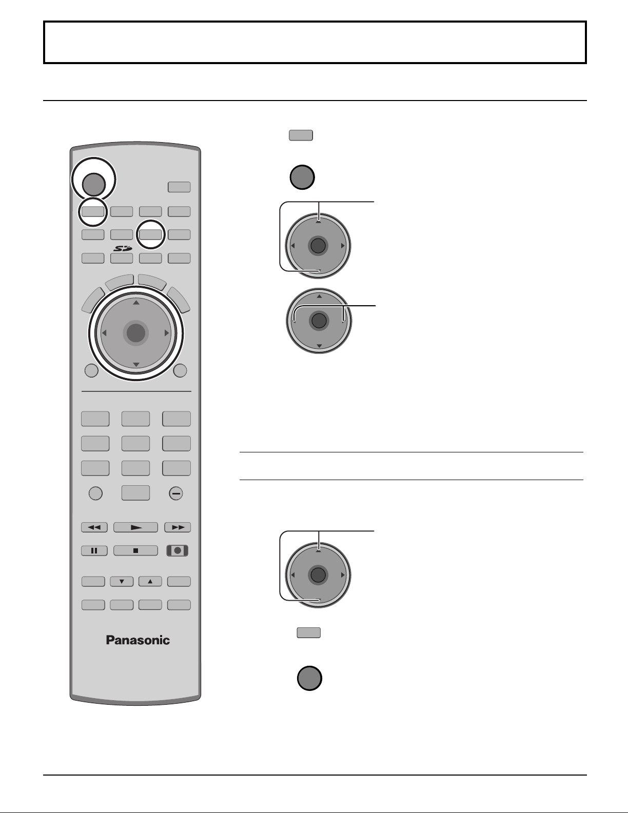
Channel
Press to select the menu.
Press to display the sub-menu.
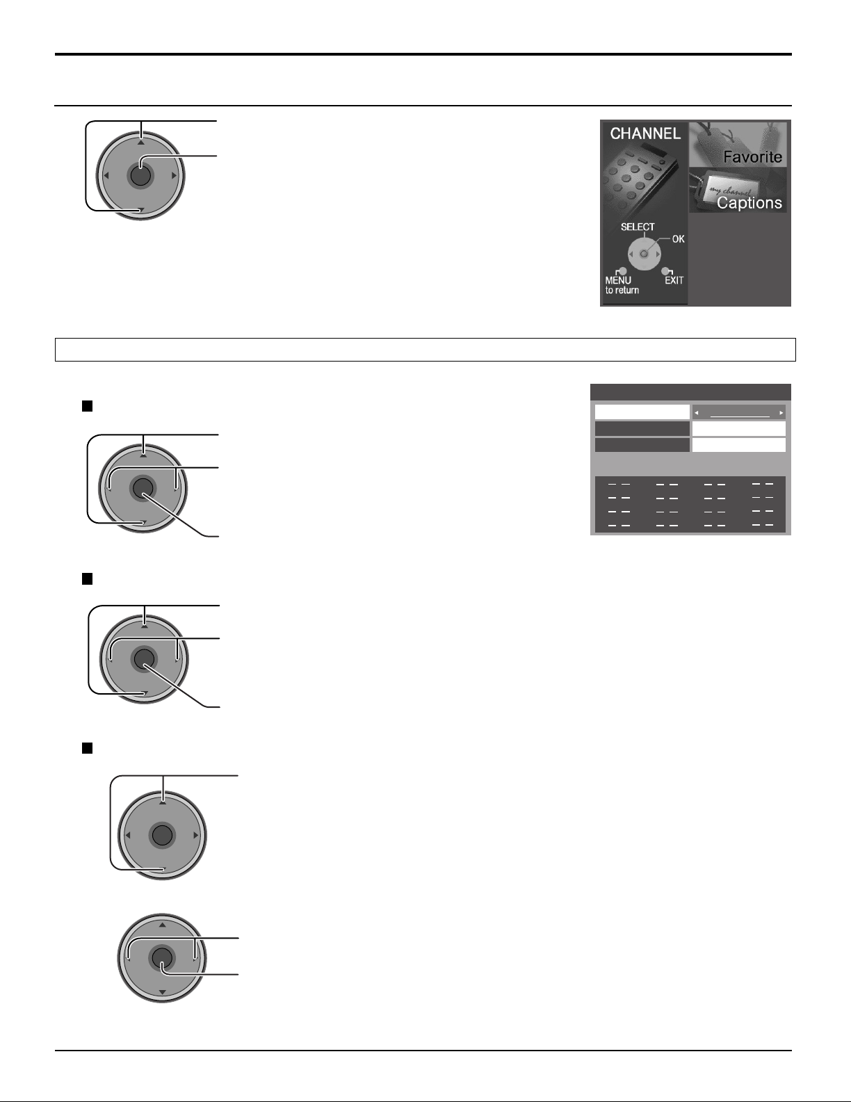
Favorite
Allows you to create Favorite channel list from Antenna (A) or Antenna (B).
Surf Mode
Press to select Surf Mode.
Press to select Favorites or All Channels.
Press to enter your selection.
RF Input
Press to select RF Input.
Press to select Antenna (A) or Antenna (B).
Press to enter your selection.
Channel
1
Press to select Channel.
Favorite
Surf Mode
RF Input
Channel
The maximum is 16 favorite channels.
All Channels
Antenna (A)
A: 2
30
2
Press to select the channel.
Press to add the channel.
To delete the channel, press again while the channel number is displayed.
• Repeat step 2 up to 16 favorite channels.
 Loading...