

Page 1
POWER
E
T
U
M
R
C
V
V
T
PC
MENU
123
456
7809
R-TUNE PROG
REW
FREEZE
TV/VCR
PIP SPLIT MOVE SWAP
SAP
T
T
V
C
/
V
E
I
D
P
E
S
O
A
L
I
G
H
T
A
U
D
X
V
D
R
C
V
R
C
B
TV
L
D
D
B
S
CH
I
O
T
C
N
A
VOL VOL
CH
RECALL
GUIDE
PAGEEXIT
PIP MAXFFPIP MIN
PLAY
REC
STOPPAUSE
PIP CH
SEARCH
VCR CH
OPEN/CLOSE
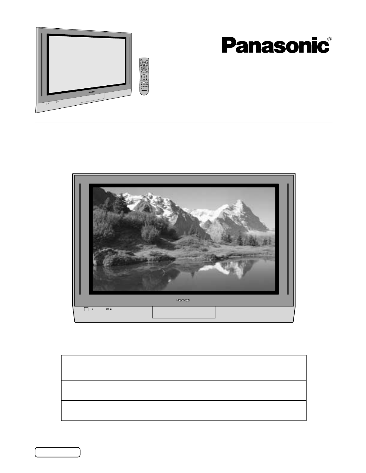
Operating Instructions
High Definition
Plasma Television
Model No.
TH-42PX20
TH-50PX20
For assistance, please call : 1-888-VIEW-PTV(843-9788)
or send e-mail to : [email protected]
or visit us at www.panasonic.com (U.S.A)
For assistance, please call : 787-750-4300
or visit us at www.panasonic.com (Puerto Rico)
For assistance, please call : 1-800-561-5505
or visit us at www.panasonic.ca (Canada)
Before connecting, operating or adjusting this product, please read these instructions completely.
Please keep this manual for future reference.
English
TQBC0628-1
Page 2
WARNING
RISK OF ELECTRIC SHOCK
DO NOT OPEN
WARNING: To reduce the risk of electric shock, do not remove cover or back.
No user-serviceable parts inside. Refer servicing to qualified service personnel.
The lightning flash with
arrow-head within a triangle
is intended to tell the user
that parts inside the product
are a risk of electric shock to
persons.
WARNING: To reduce the risk of fire or electric shock, do not expose this apparatus to rain or moisture.
Do not place liquid containers (flower vase, cups, cosmetics, etc.) above the set. (including on
shelves above, etc.)
WARNING: 1) To prevent electric shock, do not remove cover. No user serviceable parts inside. Refer servicing to
qualified service personnel.
2) Do not remove the grounding pin on the power plug. This apparatus is equipped with a three pin
grounding-type power plug. This plug will only fit a grounding-type power outlet. This is a safety feature.
If you are unable to insert the plug into the outlet, contact an electrician.
Do not defeat the purpose of the grounding plug.
The exclamation point within
a triangle is intended to tell
the user that important
operating and servicing
instructions are in the papers
with the appliance.
Note:
Do not allow a still picture to be displayed for an extended period, as this can cause a permanent afterimage to remain on the Plasma Television.
Examples of still pictures include logos, video games, computer images, teletext and images displayed in
4:3 mode.
2
HDMI, the HDMI logo and High-Definition Multimedia Interface are
trademarks or registered trademarks of HDMI Licensing LLC.
Manufactured under license from BBE Sound, Inc.
Licensed by BBE Sound, Inc. under USP4638258, 5510752 and 5736897.
BBE and BBE symbol are registered trademarks of BBE Sound, Inc.
Page 3
Important Safety Instructions
1) Read these instructions.
All the safety and operating instructions should be read before the appliance is operated.
2) Keep these instructions.
The safety and operating instructions should be retained for future reference.
3) Heed all warnings.
All warnings on the appliance and in the operating instructions should be adhered to.
4) Follow all instructions.
All operating and use instructions should be followed.
5) Do not use this apparatus near water.
For example, near a bathtub, wash bowl, kitchen sink, or laundry tub, in a wet basement, or near a swimming pool, and
the like.
6) Clean only with dry cloth.
Do not use liquid cleaners or aerosol cleaners. Use a dry cloth for cleaning.
7) Do not block any ventilation openings. Install in accordance with the manufacturer’s instructions.
Slots and Openings in the cabinet are provided for ventilation and to ensure reliable operation of the product and to
protect it from overheating. The openings should never be blocked by placing the product on a bed, sofa, rug, or other
similar surface.
8) Do not install near any heat sources such as radiators, heat registers, stoves, or other apparatus (including amplifiers)
that produce heat.
This product should not be placed in a built-in installation such as a bookcase or rack unless proper ventilation is
provided or the manufacturer’s instructions have been adhered to.
9) Do not defeat the safety purpose of the polarized or grounding-type plug. A polarized plug has two blades with one wider
than the other. A grounding type plug has two blades and a third grounding prong. The wide blade or the third prong are
provided for your safety. If the provided plug does not fit into your outlet, consult an electrician for replacement of the
obsolete outlet.
10) Protect the power cord from being walked on or pinched particularly at plugs, convenience receptacles, and the point
where they exit from the apparatus.
11) Only use attachments / accessories specified by the manufacturer.
12) Use only with the cart, stand, tripod, bracket, or table specified by the manufacturer, or sold with the
apparatus. When a cart is used, use caution when moving the cart / apparatus combination to avoid
injury from tip-over.
Quick stops, excessive force, and uneven surfaces may cause the appliance and cart combination
to overturn.
13) Unplug this apparatus during lightning storms or when unused for long periods of time.
This will prevent damage to the product due to lightning and power-line surges.
14) Refer all servicing to qualified service personnel. Servicing is required when the apparatus has been damaged in any
way, such as power-supply cord or plug is damaged, liquid has been spilled or objects have fallen into the apparatus,
the apparatus has been exposed to rain or moisture, does not operate normally, or has been dropped.
15) To prevent electric shock, ensure the grounding pin on the AC cord power plug is securely connected.
3
Page 4
Dear Panasonic Customer
Welcome to the Panasonic family of customers. We hope that you will have many years of enjoyment
from your new Plasma TV.
To obtain maximum benefit from your set, please read these Instructions before making any adjustments,
and retain them for future reference.
Retain your purchase receipt also, and record the model number and serial number of your set in the
space provided on the back cover of these instructions.
Visit our Panasonic Web Site for USA : www.panasonic.com
for Puerto Rico : www.panasonic.com
for Canada : www.panasonic.ca
For assistance, please call : 1-888-VIEW-PTV(843-9788)
or send e-mail to : [email protected]
or visit us at www.panasonic.com (U.S.A)
For assistance, please call : 787-750-4300
or visit us at www.panasonic.com (Puerto Rico)
For assistance, please call : 1-800-561-5505
or visit us at www.panasonic.ca (Canada)
4
Page 5
FCC STATEMENT
FCC STATEMENT
This equipment has been tested and found to comply with the limits for a Class B digital device, pursuant to Part 15 of
the FCC Rules. These limits are designed to provide reasonable protection against harmful interference in a residential
installation. This equipment generates, uses and can radiate radio frequency energy and, if not installed and used in
accordance with the instructions, may cause harmful interference to radio communications. However, there is no
guarantee that interference will not occur in a particular installation. If this equipment does cause harmful interference
to radio or television reception, which can be determined by turning the equipment off and on, the user is encouraged
to try to correct the interference by one or more of the following measures:
• Reorient or relocate the receiving antenna.
• Increase the separation between the equipment and receiver.
• Connect the equipment into an outlet on a circuit different from that to which the receiver is connected.
• Consult the dealer or an experienced radio/TV technician for help.
This device complies with Part 15 of the FCC Rules. Operation is subject to the following two conditions: (1) This
device may not cause harmful interference, and (2) this device must accept any interference received, including
interference that may cause undesired operation.
FCC CAUTION:
To assure continued compliance and possible undesirable interference, the provided ferrite cores must be
used when connecting this plasma display to video equipment; and maintain at least 40cm spacing to other
peripheral devices. Refer to instructions on pages 10.
Pursuant to 47CFR, Part 15.21 of the FCC rules, any changes or modifications to this TV not expressly approved
by Matushita Electric Corporation of America could result harmful interference and would void the user’s
authority to operate this device.
Any changes or modifications not expressly approved by Matsushita Electric Corporation of America could
cause harmful interference and would void the user’s authority to operate this device.
FCC Declaration of Conformity
Model No. TH-42PX20, TH-50PX20
Responsible Party: Matsushita Electric Corporation of America
One Panasonic Way, Secaucus, NJ 07094
Contact Source: Panasonic Consumer Electronics Company
1-888-843-9788
email: [email protected]
Attach the ferrite core:
The ferrite cores provided as a supplied accessory must be used when connecting this Plasma TV to video equipment.
(see page 11,12,13,14,15,18,19,21)
CANADIAN NOTICE:
This Class B digital apparatus complies with Canadian ICES-003.
Trademark Credits
VGA is a trademark of International Business Machines Corporation.
•
Macintosh is a registered trademark of Apple Computer, USA.
•
S-VGA is a registered trademark of the Video Electronics Standard Association.
•
Even if no special notation has been made of company or product trademarks, these trademarks have been fully
respected.
5
Page 6

Table of Contents
Important Safety Instructions ....................................... 3
FCC STATEMENT ........................................................... 5
Table of Contents ........................................................... 6
Safety Precautions ......................................................... 7
Installation ...................................................................... 9
Receiver Location ......................................................... 9
Optional External Equipment ........................................ 9
Remote Control Battery Installation .............................. 9
Accessories ...................................................................10
Cable Connection ......................................................... 11
Connecting the Aerial cable to the RF In Terminal .......12
Antenna Connection ............................................ 12
Connecting Headphones / Earphones ........................ 12
Front Control Panel ..................................................... 13
Optional Equipment Connections ............................... 13
Cable Box Connection ........................................ 13
VCR Connection ................................................. 14
VCR and Cable Box Connection ......................... 15
Digital TV - Set-Top Box (DTV-STB) or DVD Connection
Amplifier Connection (TO AUDIO AMP) .............. 16
Program Out Connection (PROG OUT) .............. 16
How to connect the HDMI Terminal ..............................17
PC Input Terminals connection ................................... 18
Power ON / OFF ............................................................ 19
AC cord connection ..................................................... 19
How to Turn the Power On .......................................... 19
Menu Language Selection .......................................... 19
VHF, UHF and Cable TV ................................................ 20
VHF and UHF ............................................................. 20
Cable TV ..................................................................... 21
Location of Controls .................................................... 22
Illuminated Remote Control ........................................ 22
Basic Menu Operations ............................................... 24
SET UP Operation ........................................................ 26
MENU Languages ....................................................... 26
ANTENNA Selection ................................................... 26
cc ON MUTE cc MODE (Closed Captions)............ 26
Selecting option menus in OTHER ADJ...................... 27
MODE Selection ......................................................... 28
AUTO PROGRAM ....................................................... 28
MANUAL PROGRAM.................................................. 28
AUTO POWER ON...................................................... 29
CHAN BANNER .......................................................... 29
SIDE BAR ..........................................................................
POWER SAVE ............................................................ 30
PICTURE Adjustment................................................... 30
PICTURE MODE ........................................................ 30
COLOR / TINT / BRIGHTNESS / PICTURE /
SHARPNESS / NORMAL ............................... 30
Selecting option menus in OTHER ADJ...................... 31
COLOR TEMP (Temperature) / NATURAL COLOR /
VIDEO NR / 3D Y/C FILTER..............................31
COLOR MATRIX ......................................................... 31
FREEZE ...................................................................... 32
Audio Adjustment ........................................................ 33
Selecting STEREO/SAP/MONO ................................. 33
Selecting BASS / TREBLE / BALANCE / NORMAL.... 33
Selecting option menus in OTHER ADJ...................... 33
HDMI IN ...................................................................... 33
AI SOUND ................................................................... 34
... 16
29
BBE VIVA / BBE .......................................................... 34
SURROUND ............................................................... 34
SPEAKERS ................................................................. 34
CHANNELS Adjustment .............................................. 35
CHANNEL SCAN ........................................................ 35
FAVORITE CHANNELS Selection .............................. 35
Selecting option menus in OTHER ADJ...................... 36
PRESET CAPTION ..................................................... 36
MANUAL CAPTION .................................................... 37
INPUT LABEL ............................................................. 37
TIMER ............................................................................ 38
SLEEP ........................................................................ 38
TIMER1 and TIMER2 .................................................. 38
CLOCK SET ................................................................ 40
LOCK Feature ............................................................... 41
CREATE CODE FIRST ............................................... 41
CODE .......................................................................... 41
LOCK SET ...................................................................41
CHANNEL ................................................................... 42
V-CHIP SET ................................................................ 42
U.S. TV PROGRAMS .................................................. 43
U.S. MOVIES ............................................................... 44
Canadian English ........................................................ 45
Canadian French......................................................... 46
Blocking Message ....................................................... 47
HOW LONG? .............................................................. 47
Picture in Picture Operation........................................ 48
Split Screen ................................................................... 50
ASPECT Controls ......................................................... 52
PC MENU....................................................................... 53
PICTURE Adjustment ................................................. 54
Adjusting PICTURE POSITION/SIZE ......................... 55
SYNC .......................................................................... 56
H-FREQ. (kHz)/V-FREQ. (Hz) ..................................... 56
JPEG Viewer (SD Card/PC Card) ................................. 57
Operating peripheral equipment using the remote control .....
Programming The Illuminated Remote Control
Using Access Codes ........................................ 62
Programming Without A Code
(When the code is not known).......................... 63
Infrared Codes Index................................................... 64
Mode Operational Key Chart....................................... 67
Troubleshooting Chart................................................. 69
VIDEO/COMPONENT/RGB/PC/HDMI input signals ... 70
Specifications ............................................................... 71
62
6
Page 7

Safety Precautions
WARNING
Set up
Do not place the Plasma TV on sloped or unstable surfaces.
The Plasma TV may fall off or tip over.
•
Do not place any objects on top of the Plasma TV.
If water spills onto the Plasma TV or foreign objects get inside it, a short-circuit may occur which could result in fire or
•
electric shock. If any foreign objects get inside the Plasma TV, please consult an Authorized Service Center.
Do not cover the ventilation holes.
Doing so may cause the Plasma TV to overheat, which can cause fire or damage to the Plasma TV.
•
If using the pedestal, leave a space of 3 15/16” (10 cm) or more at the top, left and right, 2 3/8”
bottom, and 2 3/4” (7 cm) or more at the rear. If using some other setting-up method, leave a space of 3 15/16” (10 cm)
or more at the top, bottom, left and right, and 3/4” (1.9 cm) or more at the rear.
Avoid installing this product near electronic equipment that easily receives electromagnetic waves.
It may cause interference in image, sound, etc. In particular, keep video equipment away from this product.
•
AC Power Supply Cord
(6 cm) or more at the
The Plasma TV is designed to operate on 120 V AC, 50/60 Hz.
Securely insert the power cord plug as far as it will go.
If the plug is not fully inserted, heat may be generated which could cause fire. If the plug is damaged or the wall socket
•
plate is loose, they should not be used.
Do not handle the power cord plug with wet hands.
Doing so may cause electric shocks.
•
Do not do anything that might damage the power cable. When disconnecting the power cable, hold the plug, not
the cable.
Do not make any modifications, place heavy objects on, place near hot objects, heat, bend, twist or forcefully pull the
•
power cable. Doing so may cause damage to the power cable which can cause fire or electric shock. If damage to the
cable is suspected, have it repaired at an Authorized Service Center.
If the Plasma TV will not be used for a long period of time, unplug the power cord from the wall outlet.
If problems occur during use
If a problem occurs (such as no picture or no sound), or if smoke or an abnormal odor is detected from the Plasma
TV, unplug the power cord immediately.
Continuous use of the TV under these conditions might cause fire or permanent damage to the unit. Have the TV
•
evaluated at an Authorized Service Center. Services to the TV by any unauthorized personnel are strongly discouraged
due to its high voltage dangerous nature.
If water or foreign objects get inside the Plasma TV, if the Plasma TV is dropped, or if the cabinet becomes damaged,
disconnect the power cord plug immediately.
A short may occur, which could cause fire. Contact an Authorized Service Center for any repairs that need to be made.
•
7
Page 8

Safety Precautions
CAUTION
This Plasma TV is for use only with the following optional accessories. Use with any other type of optional
accessories may cause instability which could result in the possibility of injury.
(All of the following accessories are manufactured by Matsushita Electric Industrial Co., Ltd.)
Pedestal (included) ............................................. TY-ST42PX20 (TH-42PX20) / TY-ST50PX20 (TH-50PX20)
•
Wall-hanging bracket (Vertical) ........................... TY-WK42PV3U
•
Wall-hanging bracket (Angled) ............................ TY-WK42PR2U
•
Display stand....................................................... TY-S42PX20U (TH-42PX20) / TY-S50PX20U (TH-50PX20)
•
Always be sure to ask a qualified technician to carry out set-up.
When using the Plasma TV
Do not bring your hands, face or objects close to the ventilation holes of the Plasma TV.
Top of the Plasma TV is usually very hot due to the high temperature of exhaust air being released through the ventilation
•
holes. Burns or personal injuries can happen if any body parts are brought too close. Placing any object near the top of the
TV could also result in heat damages to the object as well as to the TV if its ventilation holes are blocked.
Be sure to disconnect all cables before moving the Plasma TV.
Moving the TV with its cables attached might damage the cables which, in turn, can cause fire or electric shock.
•
Disconnect the power plug from the wall outlet as a safety precaution before carrying out any cleaning.
Electric shocks can result if this is not done.
•
Clean the power cable regularly to prevent it from becoming dusty.
Built-up dust on the power cord plug can increase humidity which might damage the insulation and cause fire. Unplug
•
the cord from the wall outlet and clean it with a dry cloth.
This Plasma TV radiates infrared rays, therefore it may affect other infrared communication equipment.
Install your infrared sensor in a place away from direct or reflected light from your Plasma TV.
Cleaning and maintenance
The front of the display panel has been specially treated. Wipe the panel surface gently using only a cleaning cloth
or a soft, lint-free cloth.
If the surface is particularly dirty, soak a soft, lint-free cloth in a weak detergent solution and then wring the cloth to
•
remove excess liquid. Use this cloth to wipe the surface of the display panel, then wipe it evenly with a dry cloth, of the
same type, until the surface is dry.
Do not scratch or hit the surface of the panel with fingernails or other hard objects. Furthermore, avoid contact with volatile
•
substances such as insect sprays, solvents and thinner, otherwise the quality of the surface may be adversely affected.
If the cabinet becomes dirty, wipe it with a soft, dry cloth.
If the cabinet is particularly dirty, soak the cloth in a weak detergent solution and then wring the cloth dry. Use this cloth
•
to wipe the cabinet, and then wipe it dry with a dry cloth.
Do not allow any detergent to come into direct contact with the surface of the Plasma TV.
•
If water droplets get inside the unit, operating problems may result.
Avoid contact with volatile substances such as insect sprays, solvents and thinner, otherwise the quality of the cabinet
•
surface may be adversely affected or the coating may peel off. Furthermore, do not leave it for long periods in contact
with articles made from rubber or PVC.
Note:
Do not allow a still picture to be displayed for an extended period, as this can cause a permanent after-image to remain
on the Plasma TV.
Examples of still pictures include logos, video games, computer images, teletext and images displayed in 4:3 mode.
8
Page 9
Installation
Receiver Location
This unit is intended to be used with an optional stand or entertainment center. Consult your dealer for available options. Locate for
comfortable viewing. Avoid placing where sunlight or other bright light (including reflections) will fall on the screen.
Use of some types of fluorescent lighting can reduce remote control transmitter range.
Adequate ventilation is essential to prevent internal component failure. Keep away from areas of excessive heat or moisture.
Optional External Equipment
The Video/Audio connection between components can be made with shielded video and audio cables. For best performance,
video cables should utilize 75 ohm coaxial shielded wire. Cables are available from your dealer or electronic supply store.
Before you purchase any cables, be sure you know what type of output and input connectors your various components
require. Also determine the length of cable you will need.
Remote Control Battery Installation
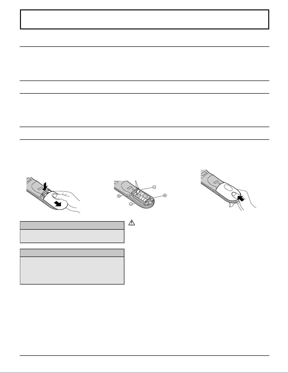
Requires two AA batteries.
1. Turn the Transmitter face down.
Remove top cover by pressing
down on marking and sliding cover
off in the direction indicated.
2. Install the batteries as shown in the
battery compartment. (Polarity + or
– must match the markings in the
compartment).
3. Replace the cover and slide in
reverse until the lock snaps.
Helpful Hints:
For frequent remote control users, replace old
batteries with alkaline batteries for longer life.
Helpful Hints:
Whenever you remove the batteries, you may
need to reset the remote control infrared
codes. We recommend that you record the code
on page 59, prior to setting up the remote control.
Two AA size
Precaution on battery use
Incorrect installation can cause battery leakage and corrosion that
will damage the remote control transmitter.
Observe the following precautions:
1. Batteries should always be replaced as a pair. Always use new
batteries when replacing the old set.
2. Do not combine a used battery with a new one.
3. Do not mix battery types (example: “Zinc Carbon” with “Alkaline”).
4. Do not attempt to charge, short-circuit, disassemble, heat or burn
used batteries.
5. Battery replacement is necessary when remote control acts
sporadically or stops operating the TV set.
9
Page 10
Accessories
Accessories Supplied
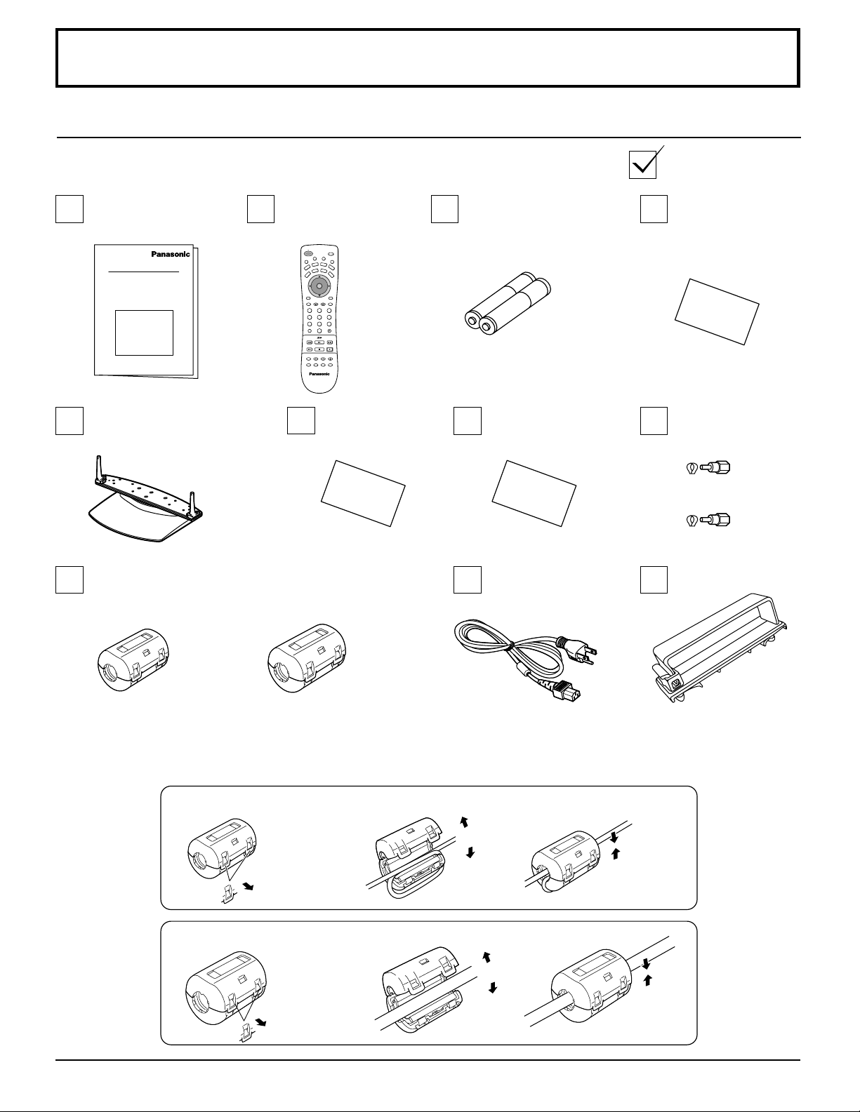
Check that you have the Accessories and items shown
Operating
Instruction book
Pedestal
TY-ST42PX20 (TH-42PX20)
TY-ST50PX20 (TH-50PX20)
Ferrite core
(small size) (×5)
(large size) (×6) TH-42PX20
Remote Control
Transmitter
EUR7603ZB0
SAP
POWER
T
V
T
/
C
V
E
I
D
P
E
S
O
A
L
E
I
G
T
H
U
T
M
A
U
D
X
V
D
RCVR
VCR
C
V
B
T
L
D
DBS
V
T
CH
O
I
T
N
C
A
VOL VOL
CH
PC
RECALL
MENU
GUIDE
PAGEEXIT
123
456
7809
R-TUNE PROG
PIP MAXFFPIP MIN
PLAY
REW
REC
STOPPAUSE
FREEZE
PIP CH
SEARCH
VCR CH
TV/VCR
OPEN/CLOSE
PIP SPLIT MOVE SWAP
Customer Card
(×7) TH-50PX20
Batteries for the Remote
Control Transmitter
(AA Battery × 2)
Service
Center List
AC cord
Warranty
F Type Antenna
Adapter
(for 3C-2V) (×2)
(for 5C-2V) (×2)
Clamper
(×2)
Installing the ferrite core
Be sure to choose the appropriate size of ferrite core (large or small) and the correct setting of the cable (winding or
passing), as indicated by each connection diagram on the following pages (12 to 21).
(Winding the cable around the ferrite core)
1
Pull back the tabs
(in two places)
(Passing the cable through the ferrite core)
1
Pull back the tabs
(in two places)
2
3
Open
Close the
ferrite core
2
3
Open
Close the
ferrite core
10
Page 11
Cable Connection
Front AV terminal
(see page 13)
From EXTERNAL monitor terminal
on Computer (see page 18)
COMPONENT VIDEO INPUT
S VIDEO
PROG OUT
VIDEO
L
TO AUDIO
AMP
R
12
INPUT
12
S-VIDEO
Y
P
B
VIDEO
P
R
VIDEO
INPUT 3
L AUDIO R
PC
ANT 1 ANT 2SPLIT
OUT
SD CARD
PUSH-EJECT
ACTIONINPUT VOLUME CHANNEL
PC CARD
EJECT
HPJ
PC
L AUDIO R
S-VIDEO
VIDEO
INPUT 3
AV terminals
(see page 14,15,17)
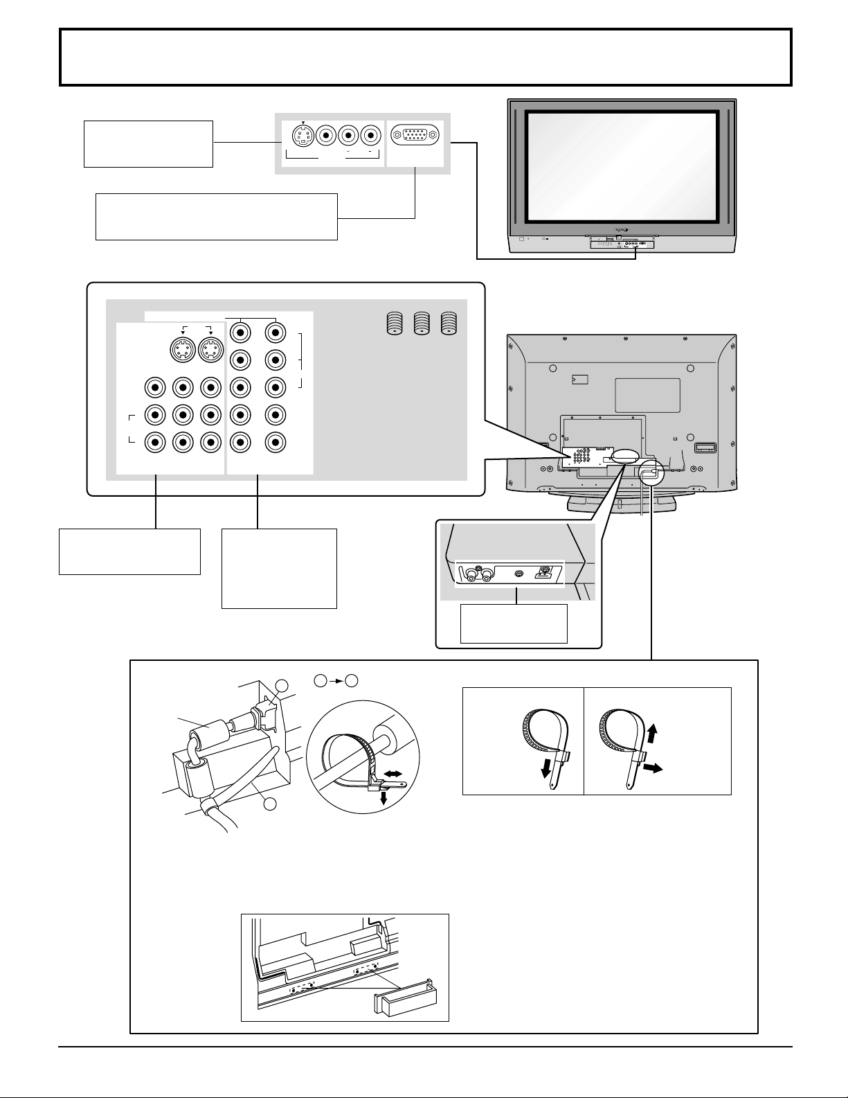
— Fastening of power and other cables
Ferrite core
(large size)
(supplied)
Fastening method of power cable
For other cables, attach the band on
the installation hole, and fasten them.
COMPONENT
and Audio
Input terminals
(see page 16)
1
2
Clamper
1 2
HDMI terminal
(see page 17)
Fastening band
Fastening Loosening
Pull off.
Keep
the knob
To tighten.
pressed.
Fastening method of power cable
1. Insert the power plug into the main body.
2. Fasten with the power cable fastening band.
3. Bundle the cable with the cable fastening
clamper.
11
Page 12
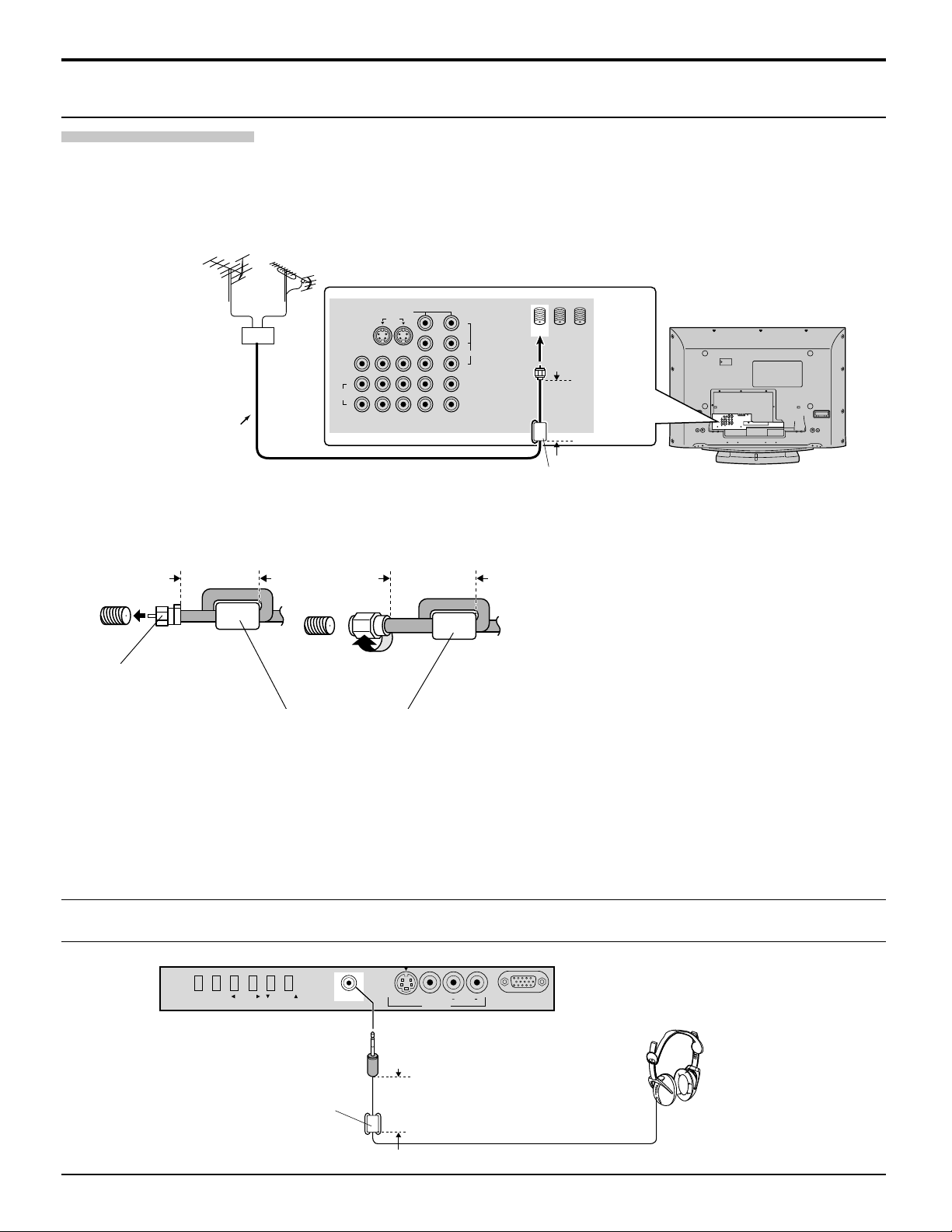
Cable Connection
Connecting the Aerial cable to the RF In Terminal
Antenna Connection
• For proper reception of VHF/UHF channels, an external antenna is required. For best reception, an outdoor antenna is
recommended. Antenna Mode must be set to TV.
• Incoming Cable from Home Antenna
Connect home antenna to ANT1 connection on back of television. Select TV mode and ANT1 in the SET UP menu.
( Cable Mode is preset at the factory. Antenna users must change to TV mode and select ANT1 in the Set Up Menu.)
VHF Aerial
UHF Aerial
Mixer
VIDEO
TO AUDIO
AMP
S VIDEO
PROG OUT
L
R
COMPONENT VIDEO INPUT
INPUT
12
12
Y
P
B
VIDEO
P
R
ANT 1 ANT 2SPLIT
OUT
Less than
4” (10 cm)
75 Ohm
Coaxial Cable
Ferrite core (large size)
Incoming Cable from
Home Antenna
Less than
4” (10 cm)
Incoming Cable from
Cable Company
Less than
4” (10 cm)
(supplied)
Note: Certain cable systems offset some channels
to reduce interference or have Premium
(scrambled) channels. A cable converter box
is required for proper reception. Check with
your local Cable company for its compatibility
requirements.
F-Type Antenna
Adapter (supplied)
75 Ohm VHF/UHF
on back of TV
Ferrite core (large size)
Notes:
(supplied)
(1) To obtain optimum quality picture and sound, an Aerial, the correct cable (75 Ohm coaxial) and the correct terminating
plug are required.
(2) If a communal Aerial system is used, you may require the correct connection cable and plug between the wall Aerial
socket and your television receiver.
(3) Your local Television Service Centre or Dealer may be able to assist you in obtaining the correct Aerial system for your
particular area and the accessories required.
(4) Any matters regarding Aerial installation, upgrading of existing systems or accessories required, and the costs incurred,
are the responsibility of you, the Customer.
Connecting Headphones / Earphones
Connect headphones / earphones as follows.
ACTION INPUT VOLUME CHANNEL
HPJ
(M3 plug)
S-VIDEO
VIDEO
INPUT 3
L AUDIO R
PC
Less than
Ferrite core (small size)
4” (10 cm)
(supplied)
You can listen to sound from the headphone Jack.
12
(Optional)
Page 13
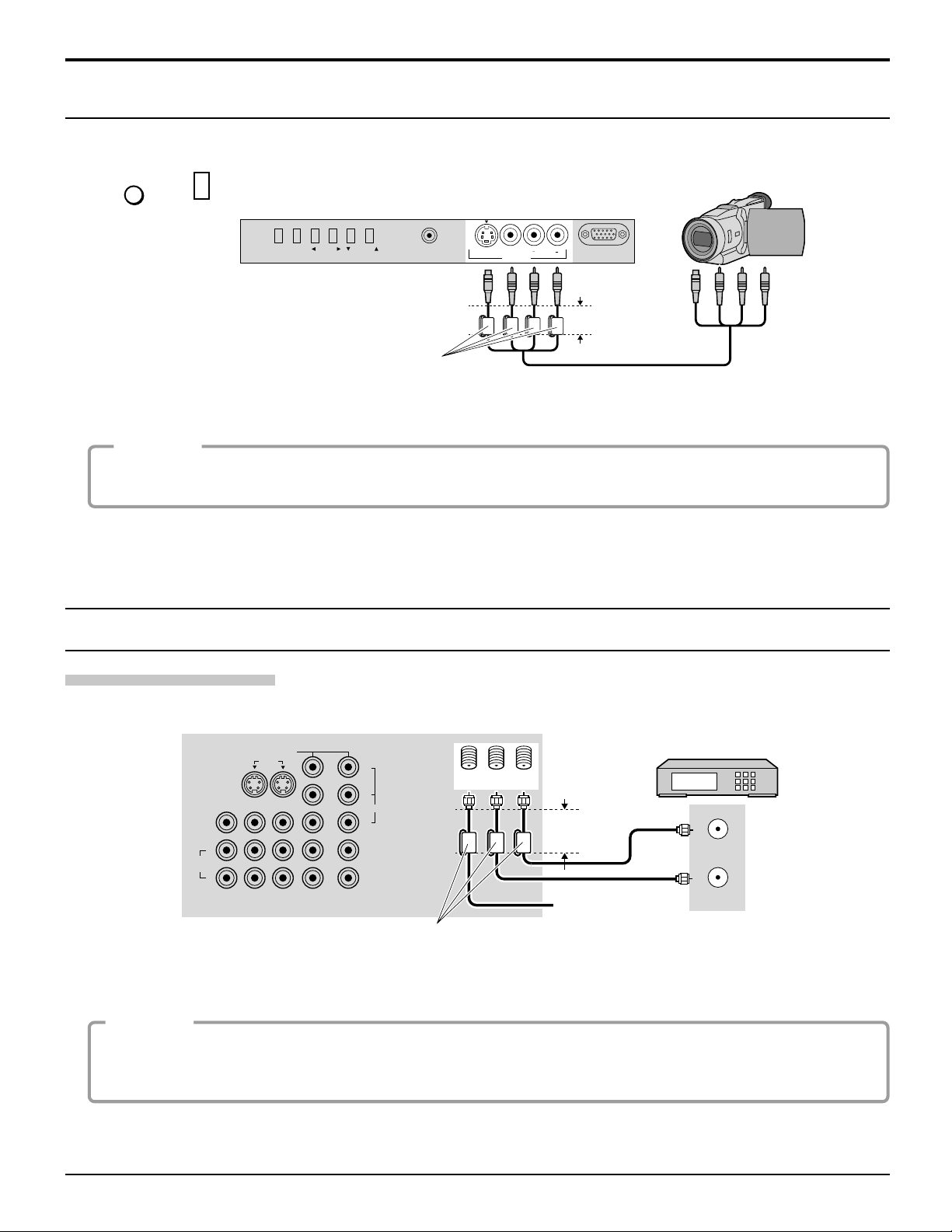
Cable Connection
Front Control Panel
Push to open the front panel of the television to use the TV without remote control or to use the Audio/Video input jacks for
optional equipment.
Press
TV/VIDEO
or
to select VIDEO 3 input mode.
INPUT
CAMCORDER
ACTION INPUT VOLUME CHANNEL
HPJ
S-VIDEO
VIDEO
INPUT 3
L AUDIO R
PC
Note:
The front control panel can be used to access menus and
switch video mode when the remote control is not
available.
Less than
4” (10 cm)
Ferrite core (small size)
(supplied)
A second VCR, video disc player, video game equipment and DSS equipment can also be connected to the video inputs.
See the optional equipment manual for details.
Procedure
1. Connect equipment to front Audio/Video input jacks.
2. Operate optional equipment as instructed in equipment manual.
Note:
The S-VIDEO connection provides higher quality picture. It overrides other VIDEO connections. Use INPUT 3, AUDIO L
and R with S-VIDEO connection.
Optional Equipment Connections
Cable Box Connection
Follow this diagram when connecting your television to a cable box only.
CONNECTIONS ON BACK OF TV
COMPONENT VIDEO INPUT
S VIDEO
PROG OUT
VIDEO
L
TO AUDIO
AMP
R
12
INPUT
12
P
P
Y
B
VIDEO
R
ANT 1 ANT 2SPLIT
OUT
Less than
4” (10 cm)
Incoming Cable
Ferrite core (large size)
(supplied)
CABLES NOT
SUPPLIED
Note: The remote control must be programmed with supplied codes to operate the cable box (see page 61).
Viewing a premium (scrambled) cable channel
Procedure
1. Select ANT2 in the SET UP menu.
2. Tune the television to Channel 3 or Channel 4.
3. Using the cable box, tune to the premium cable channel you would like to view.
CABLE BOX
ANT OUTPUT
ANT INPUT
Note:
To use special features such as Favorite Channels and Channel Captions, ANT1 must be selected in the SET UP menu
(see page 26).
13
Page 14
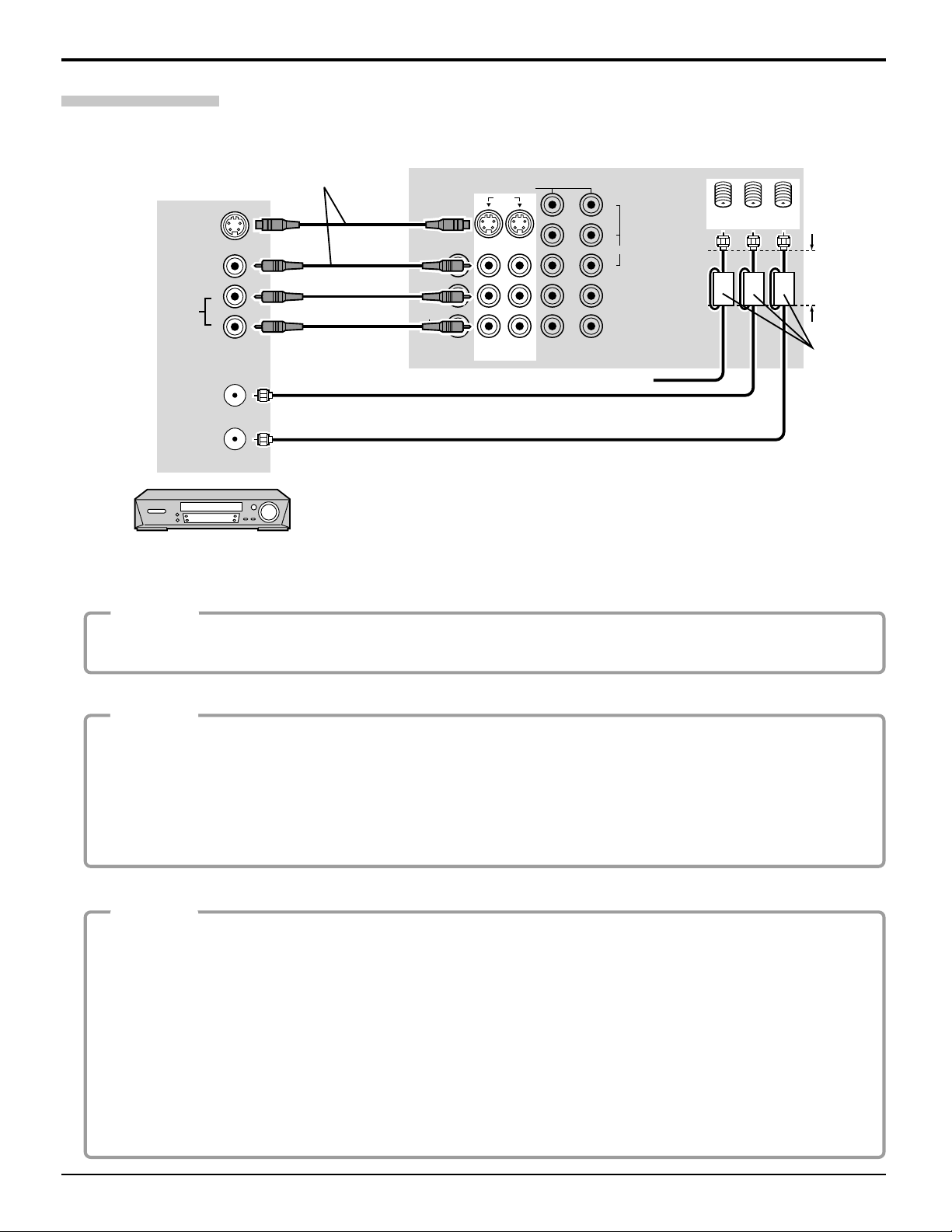
Cable Connection
VCR Connection
Follow this diagram when connecting your television to a VCR only.
Use either the S-Video or
the Video connection.
S-VIDEO
VIDEO
L
AUDIO
R
ANT INPUT
VIDEO
TO AUDIO
AMP
PROG OUT
L
R
CONNECTIONS ON BACK OF TV
COMPONENT VIDEO INPUT
INPUT
12
S VIDEO
12
Y
P
PR
B
VIDEO
Incoming Cable
ANT 1 ANT 2
SPLIT
OUT
Less than
4” (10cm)
Ferrite core
(large size)
(supplied)
ANT OUTPUT
CABLES NOT SUPPLIED
VCR
Note: The remote control must be programmed with supplied codes to operate the VCR (see page 59, 60).
Viewing a television program
Procedure
1. Select ANT1 in the SET UP menu. (See page 26)
2. Tune the television to the television program you would like to view.
Viewing a video
Procedure
• Option A
1.
Press the TV/VIDEO button on the remote control to select the video input (VIDEO 1, VIDEO 2, etc.) connected to your VCR.
2. Begin the video.
• Option B
1. Select ANT2 in the SET UP menu.
2. Tune the television to Channel 3 or 4, depending on your VCR.
3. Begin the video.
Recording a television program
Procedure
• Option A (Recording and viewing the same program)
1. Select ANT2 in the SET UP menu.
2. Tune the television to Channel 3 or 4, depending on your VCR.
3. Using the VCR, tune to the television program you would like to record.
4. Begin recording.
• Option B (Recording one program while viewing another program)
1. Select ANT1 in the SET UP menu.
2.
Press the TV/VIDEO button on the remote control to select the video input (VIDEO 1, VIDEO 2, etc.) connected to your VCR.
3. Using the VCR, tune to the television program you would like to record.
4. Begin recording.
5. Press the TV/VIDEO button on the remote control to switch back to TV mode.
6. Tune the television to the program you would like to view.
14
Page 15
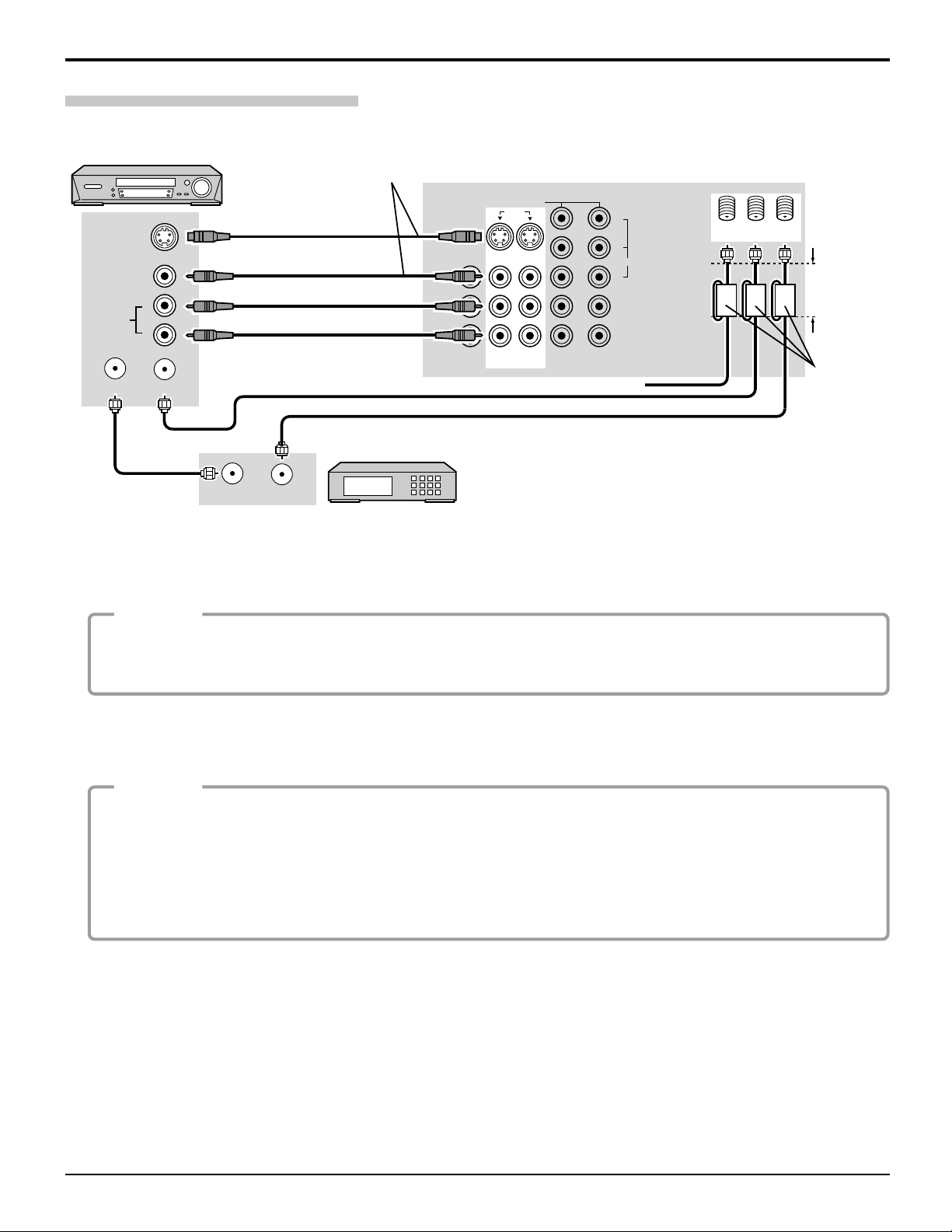
VCR and Cable Box Connection
Follow this diagram when connecting your television to both a VCR and a cable box.
VCR
Use either the S-Video or
the Video connection.
CONNECTIONS ON BACK OF TV
Cable Connection
S-VIDEO
AUDIO
VIDEO
COMPONENT VIDEO INPUT
12
S VIDEO
PROG OUT
VIDEO
L
R
TO AUDIO
AMP
L
R
CABLES NOT SUPPLIED
ANT INPUTANT OUTPUT
12
INPUT
Incoming Cable
Y
P
PR
B
VIDEO
SPLIT
ANT 1 ANT 2
OUT
Less than
4” (10 cm)
Ferrite core
(large size)
(supplied)
CABLE BOX
ANT OUTPUTANT INPUT
Note: The remote control must be programmed with supplied codes to operate the VCR and cable box
(see page 59 - 61).
Viewing a premium (scrambled) cable channel
Procedure
1. Select ANT2 in the SET UP menu.
2. Tune the television to Channel 3 or Channel 4.
3. Using the cable box, tune to the premium cable channel you would like to view.
Note: To use special features such as Favorite Channels and Channel Captions, ANT1 must be selected in the SET UP
menu (see page 26).
Recording a premium (scrambled) cable channel
Procedure
1. Select ANT2 in the SET UP menu.
2. Press the TV/VIDEO button on the remote control to select the video input (VIDEO 1, VIDEO 2, etc.) connected
to your VCR.
3. Turn the VCR ON.
4. Tune the VCR to Channel 3 or 4, depending on the switch setting on the back of VCR.
5. Using your cable box, tune to the premium cable channel you would like to record.
6. Begin recording.
Note: To view a different channel while recording:
• Select ANT1 in the SET UP menu.
• Press the TV/VIDEO button on the remote control to TV mode.
• Tune the television to a program (except another premium cable channel).
Notes:
(1) Similar connections are available at the INPUT 1, 2, 3 input terminals.
Input 3 is located on the front of the unit.
Select the desired VIDEO input position by pressing the TV/VIDEO button. (See page 23)
(2) When connecting video cables, priority is given to the S-Video cable when the S-Video input terminal and the video
input terminal are connected at the same time.
15
Page 16
Cable Connection
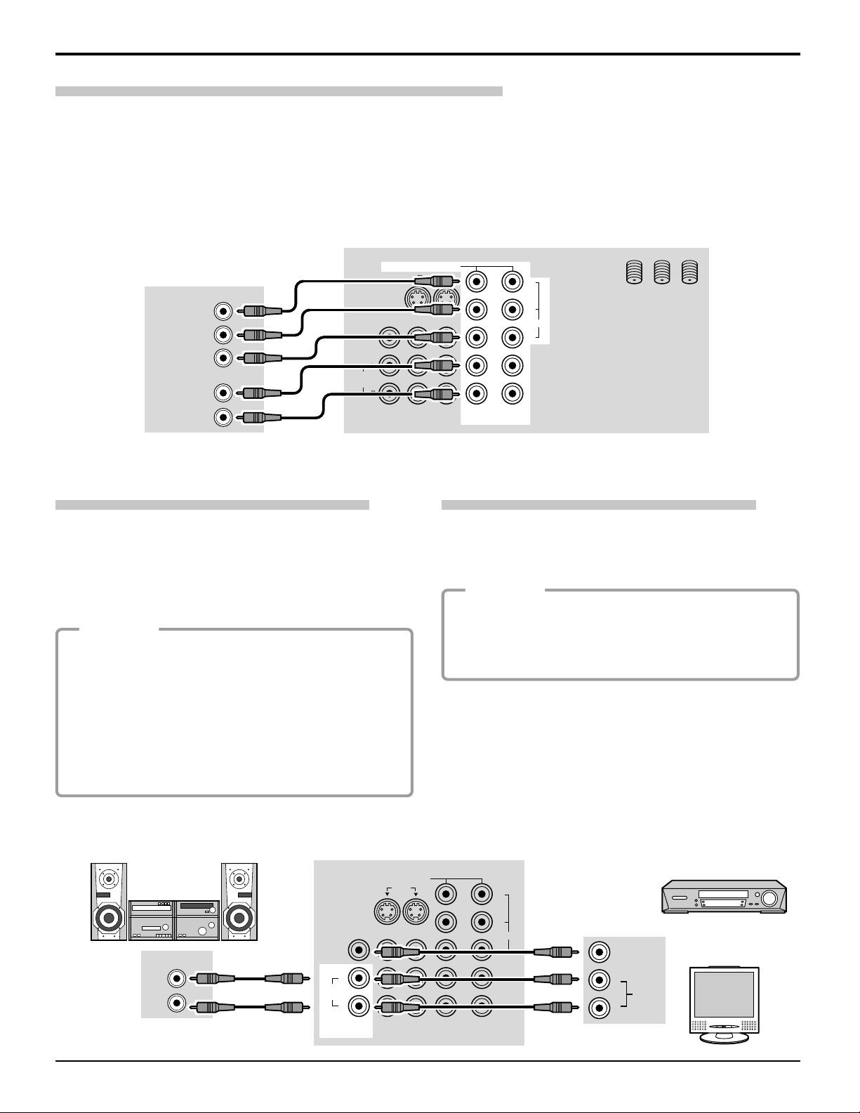
Digital TV - Set-Top Box (DTV-STB) or DVD Connection
This television is capable of displaying 1080i and 480p DTV signals when connected to a DTV Tuner set-top-box (STB). In
order to view DTV programming, the STB must be connected to the component video inputs (Y, PB , PR ) of the television.
A DTV signal must be available in your area. Select the output of the STB to either 1080i or 480p.
This television also utilizes a progressive scan doubler, which de-interlaces the NTSC signal and progressively scans the
image. This allows you to sit close to the TV and not see the thin black horizontal lines (venetian blind effect) associated
with interlaced TV pictures.
Use this diagram to connect the Panasonic DTV-STB (Digital TV-Set-Top Box) or DVD Player to the back of your TV.
DTV INPUT TERMINALS ON BACK OF TV
CABLES NOT SUPPLIED
DIGITAL TV OUTPUT
Y
MAIN
VIDEO
P
B
P
R
AUDIO OUTPUT
L
R
VIDEO
TO AUDIO
AMP
S VIDEO
PROG OUT
L
R
COMPONENT VIDEO INPUT
INPUT
12
12
Y
P
P
B
VIDEO
R
SPLIT
ANT 1 ANT 2
OUT
Note:
There are 2 sets of three video inputs, Y, PB , and PR . Separated component color inputs provide luminance and color
separation. Furthermore, the L (left) and R (right) audio inputs must be used.
Amplifier Connection (TO AUDIO AMP)
To listen through a separate stereo system, connect an
external audio amplifier TO AUDIO AMP outputs on back
of television.
Program Out Connection (PROG OUT)
To use the television audio and video with optional
equipment, connect the PROG OUT and TO AUDIO AMP
connections on the back of the television.
Note: TO AUDIO AMP terminals cannot be connected
directly to external speakers.
Audio Adjustments
Procedure
1. Select SPEAKERS ON located in the onscreen
AUDIO menu.
Procedure
1. Connect optional equipment to PROG OUT and TO
AUDIO AMP terminals.
2. PROG OUT terminal display is the same as onscreen
display.
2. Set amplifier volume to minimum.
3. Adjust television volume to desired level.
4. Adjust amplifier volume to match the television.
See optional equipment manual for further instructions for
recording and monitoring.
5. Select SPEAKERS OFF & VARIABLE AUDIO OUT
from AUDIO menu.
6. Volume, mute, bass, treble and balance are now
controlled through the television.
Select SPEAKERS OFF & FIXED AUDIO OUT to control
audio functions through the external amplifier.
External Amplifier
AUDIO INTPUT
L
R
CONNECTIONS ON BACK OF TV
COMPONENT VIDEO INPUT
INPUT
12
S VIDEO
PROG OUT
VIDEO
L
TO AUDIO
AMP
R
CABLES NOT SUPPLIED
16
12
Y
P
P
B
VIDEO
R
L
R
VIDEO
VCR
OR
MONITOR
AUDIO
Page 17
Cable Connection
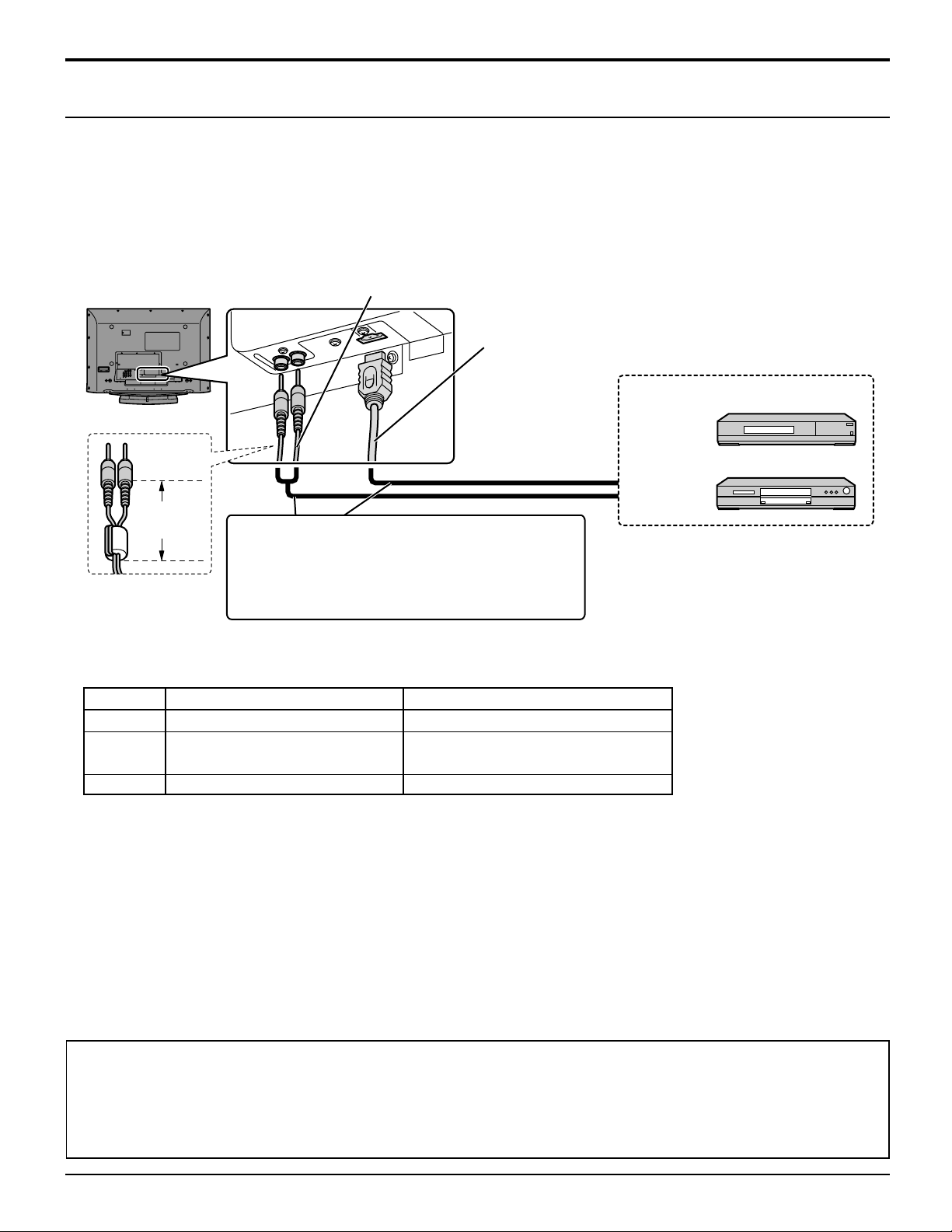
How to connect the HDMI Terminal
(HDMI : High Definition Multi media Interface)
1
∗
HDMI
both video and audio information.
This HDMI
Top Box or DVD player equipped with HDMI or DVI output connection.
By inputting a High-bandwidth Digital Content Protection (HDCP) high-definition picture source to the HDMI terminal of
this television, high-definition pictures can be displayed on the screen in their digital form.
is the first all digital consumer electronics A/V interface that supports uncompressed standard. One jack supports
1
∗
input can be connected to an EIA/CEA-861/861B
Audio Cable (not included)
Less than
4"(10 cm)
If the external device has DVI output only, use a
DVI to HDMI adaptor cable
jack. Also, connect the Audio out signal from the
external device.
(Set Top Box or DVD player) to the AUDIO IN
side the HDMI input.
3
∗
to connect to the HDMI
HDMI Cable(not included)
2
∗
compliant consumer electronic device, such as a Set
Set Top Box
DVD player
HDMI
signal out
4
∗
jacks
Applicable VIDEO Signal
This model support following format.
Please adjust the format of connecting equipment.
× ×
×
× ×
×
× ×
1,080i
480P
480P
× ×
×
× ×
× ×
480i
V)
Vertical scanning frequency(Hz)
59.94/60
59.94/60
59.94/60
59.94/60
No. of dots (H
1080i
480P
480i
This input terminal is not intended for use with computers.
AUDIO signal (L.PCM)
when the digital sound signal is included at connecting HDMI equipment.
Sumpling freguency
48KHz / 44.1KHz / 32 KHz
Notes:
(1)This HDMI connector is Type A.
(2)If you cannot display the picture because your Digital Set Top Box does not have a Digital OUT terminal Output setting,
use the component Video input (or the S video Input or Video Input). In this case the picture will be displayed as an
analog signal.
(3) HDMI-DVI conversion cable (TY-SCHO3DH):available on Panasonic Website.
(www.panasonic.com)
1. HDMI, the HDMI logo and High-Definition Multimedia Interface are trademarks or registered trademarks of HDMI
∗
Licensing LLC.
2. EIA/CEA-861/861B profiles compliance covers profiles for transmission of uncompressed digital videoincluding
∗
high bandwidth digital content protection.
3. Consult your consumer electronics dealer for availability details.
∗
4. (HDMI IN)Please refer to page 24.
∗
The HDMI terminal of this equipment is TYPE A.
•
1,920
× ×
×
× ×
720
× ×
×
× ×
640
720(1,440)
17
Page 18
Cable Connection
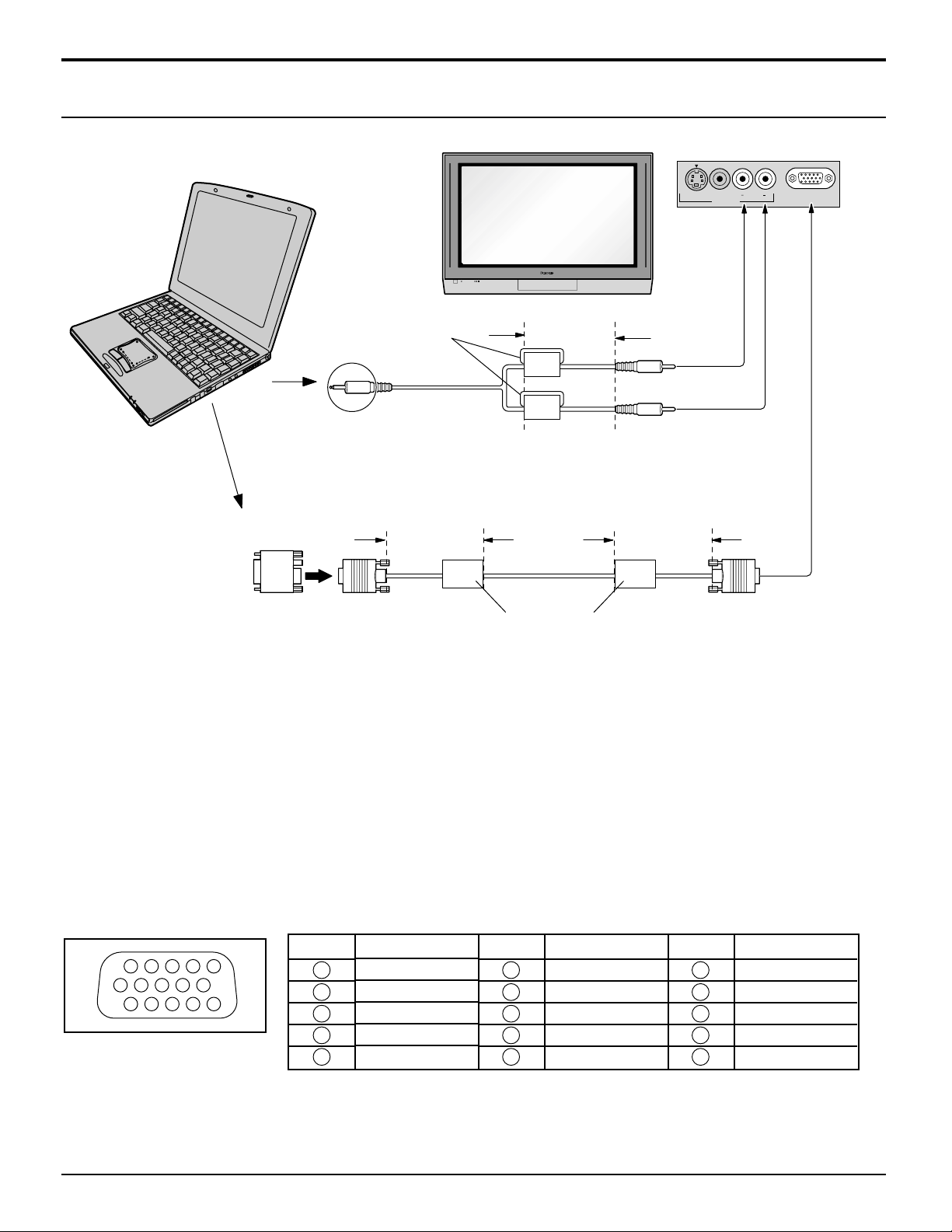
PC Input Terminals connection
COMPUTER
S-VIDEO
VIDEO
INPUT 3
L AUDIO R
PC
Ferrite core (small size)
(supplied)
Less than
4" (10 cm)
Audio
Stereo plug
Connect a cable which matches
the audio output terminal on the computer.
Conversion adapter
(if necessary)
Less than
4" (10 cm)
Less than
4" (10 cm)
RGB
PC cable
D-sub 15p
Ferrite core (large size)
(supplied)
Notes:
(1) Computer signals which can be input are those with a horizontal scanning frequency of 15 to 110 kHz and vertical
scanning frequency of 48 to 120 Hz. (However, the image will not be displayed properly if the signals exceed 1,200 lines.)
(2) The display resolution is a maximum of 768 × 768 dots (TH-42PX20), 1,024 × 768 dots (TH-50PX20) when the
aspect mode is set to “4:3”, and 1,024 × 768 dots (TH-42PX20), 1,366 × 768 dots (TH-50PX20) when the aspect
mode is set to “16:9”. If the display resolution exceeds these maximums, it may not be possible to show fine detail
with sufficient clarity.
(3) Some PC models cannot be connected to the set.
(4) There is no need to use an adapter for computers with DOS/V compatible D-sub 15P terminal.
(5) The computer shown in the illustration is for example purposes only.
(6) Additional equipment and cables shown are not supplied with this set.
(7) Do not set the horizontal and vertical scanning frequencies for PC signals which are above or below the specified
frequency range.
Signal Names for D-sub 15P Connector
Pin No.
1514131211
67839
1
2
10
45
Pin Layout for PC Input
Terminal
1
2
3
4
5
18
Signal Name
R
G
B
NC (not connected)
GND (Ground)
Pin No.
6
7
8
9
10
Signal Name
GND (Ground)
GND (Ground)
GND (Ground)
NC (not connected)
GND (Ground)
Pin No.
11
12
13
14
15
Signal Name
NC (not connected)
NC
HD/SYNC
VD
NC
Page 19
Power ON / OFF
POWER
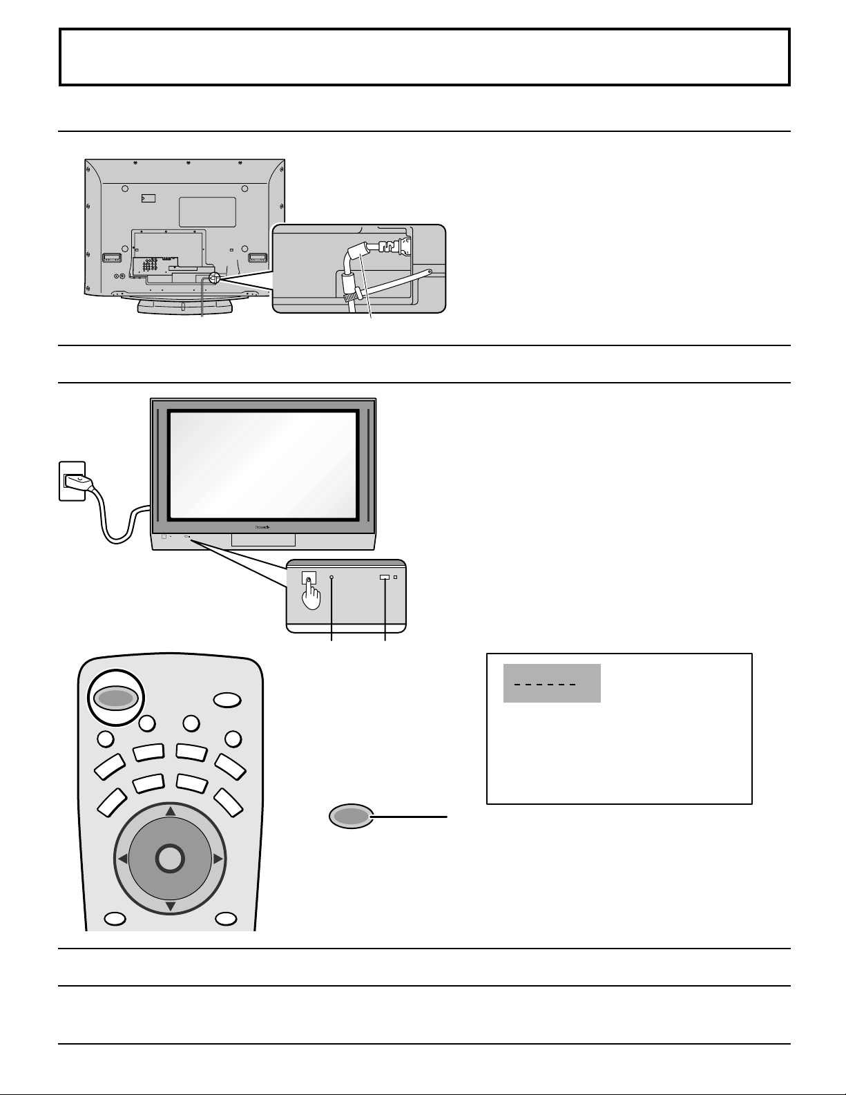
AC cord connection
Connecting the AC cord plug to the Plasma TV.
Ferrite core (large size) (supplied)
How to Turn the Power On
Fix the AC cord plug securely to the
Plasma TV with the clamper.
Connecting the Plug to the Wall Outlet
Note:
The TV’s power cord must first be plugged into the wall
outlet and then turned on at the POWER switch (standby
mode).
U
M
POWER
E
T
VCR
TV
PC
MENU
T
V
T
/
V
C
E
P
S
A
AUX
DVD
CBL
TV
D
CH
O
I
T
N
C
A
VOL VOL
CH
I
D
E
SAP
O
L
RCVR
DBS
RECALL
Press the POWER switch on the TV to turn the set on.
POWER-ON: Red
When the set is on press the POWER switch on the TV
to turn the set off.
STANDBY: No light
Example: The screen below is displayed for a while after
the TV is turned on. (setting condition is an
example.)
POWER
Remote
Control
senser
CH 3
SAP
VIVID
JUST
Press the POWER button on the remote control to turn
Power
indicater
I
G
H
T
the TV on: Red
Press the POWER button on the remote control to turn
the TV off: No light (standby)
Note:
The TV will still consume some power as long as the power cord is still inserted
into the wall outlet.
Menu Language Selection
In SET UP Menu, Select IDIOMA/LANGUE to change menu language to ENGLISH, ESPAÑOL (Spanish) or FRANÇAIS
(French). (refer to page 26)
19
Page 20
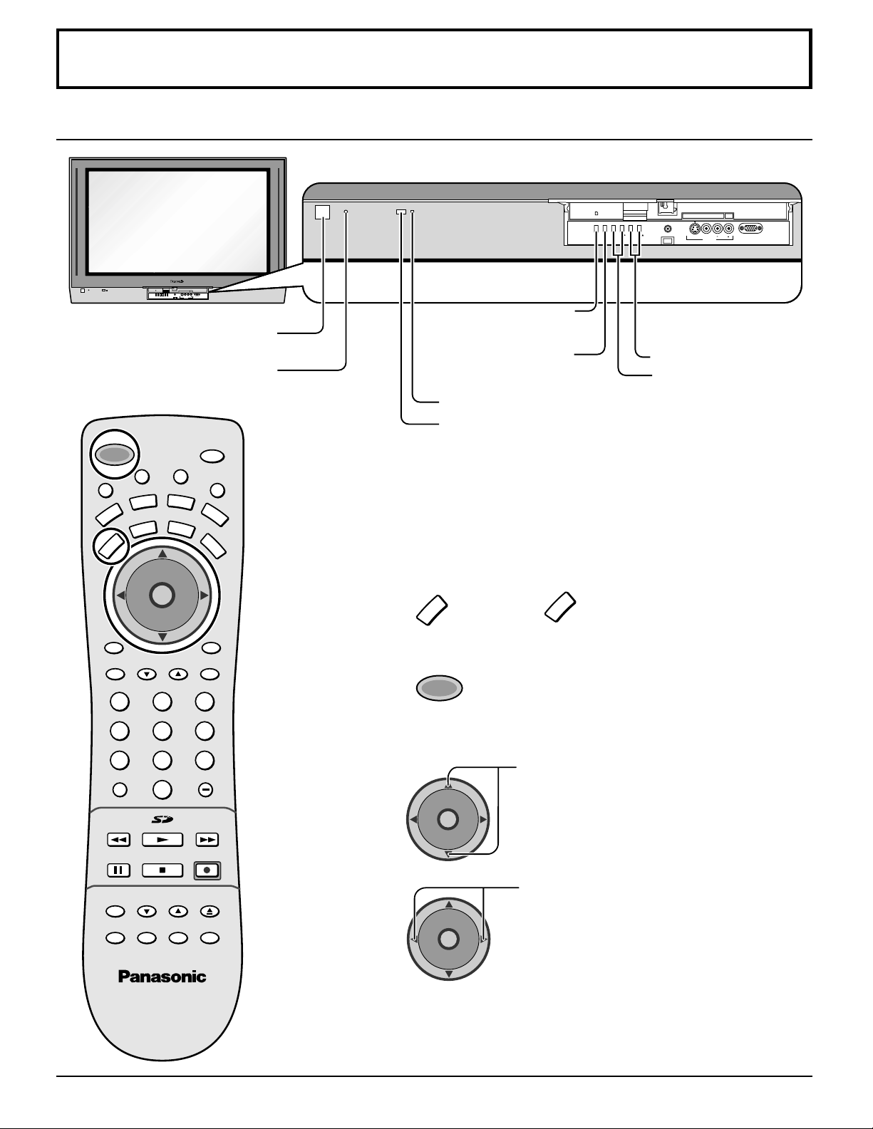
HPJ
PC CARD
EJECT
SD CARD
PUSH-EJECT
ACTION INPUT VOLUME CHANNEL
S-VIDEO
PC
VIDEO
INPUT 3
L AUDIO R
VHF, UHF and Cable TV
VHF and UHF
PC CARD
SD CARD
EJECT
PUSH-EJECT
HPJ
ACTIONINPUT VOLUME CHANNEL
PC
L AUDIO R
S-VIDEO
VIDEO
INPUT 3
Power switch
Power indicator
SAP
T
V
/
V
I
D
E
O
L
I
G
H
T
AUX
RCVR
CBL
DBS
O
I
N
1
RECALL
TV
M
T
U
POWER
E
VCR
TV
PC
MENU
T
C
E
P
S
A
DVD
DTV
CH
T
C
A
VOL VOL
CH
ACTION button
(Press to make
selections.)
INPUT button
(Change to input
signal.)
Operation can be done
from the TV set.
Channel selectors
•
Volume adjusters
•
Remote control sensor
C.A.T.S sensor
Plasma C.A.T.S (Contrast Automatic Tracking System)
Plasma C.A.T.S automatically senses the ambient light
conditions and adjusts the brightness and gradation
accordingly, to optimise contrast.
(Effective when Picture mode is set to Auto.)
Press
to operate the TV set with the remote
TV
control.
PAG EEXIT
GUIDE
123
456
7809
R-TUNE PROG
PIP MIN
REW
FREEZE
TV/VCR
VCR CH
PIP SPLIT MOVE SWAP
PLAY
STOPPAUSE
PIP CH
PIP MAX
FF
REC
SEARCH
OPEN/CLOSE
2
3
4
POWER
CH
O
I
T
N
C
A
VOL VOL
CH
CH
O
I
T
N
C
A
VOL VOL
CH
Press to turn the TV on (See page 19).
Press to select the desired channel.
Select the desired volume level.
Notes:
(1) The channel number and volume level remain the same even after
the TV is turned off.
(2) Power consumption and howling sound can be reduced if the volume
level is lowered.
20
Page 21
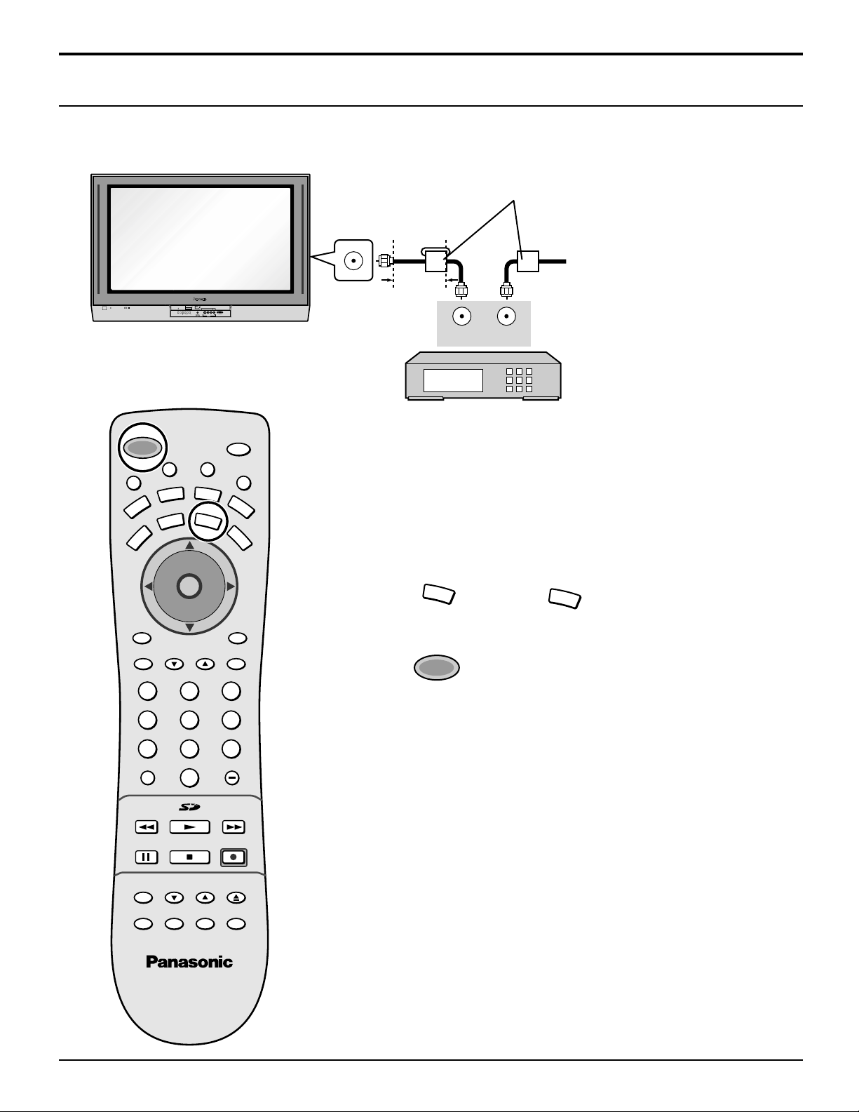
VHF, UHF and Cable TV
Cable TV
When the antenna cable is connected to the TV antenna terminal via a cable box or VCR, set the TV channel to CH3 or CH4.
This does not apply when signal is input from VIDEO INPUT.
Ferrite core (large size)
(supplied)
ANTENNA TERMINAL ON
THE BACK OF THE TV
To Antenna
Input
Incoming Cable from Antenna
or Cable TV System.
SD CARD
PUSH-EJECT
HPJ
ACTIONINPUT VOLUME CHANNEL
L AUDIO R
S-VIDEO
VIDEO
INPUT 3
M
POWER
E
T
U
VCR
PC
MENU
TV
T
V
T
/
C
E
P
S
A
AUX
DVD
CBL
DTV
CH
O
I
T
N
C
A
VOL VOL
CH
PAG EEXIT
V
I
D
123
PC CARD
EJECT
PC
E
O
RECALL
GUIDE
SAP
RCVR
DBS
Less than
4” (10 cm)
OUTPUT
CABLE BOX
L
I
G
H
T
Confirming
INPUT
Confirm that registration with cable TV provider and connection of
equipment are completed. Turn the CABLE BOX on and select the desired
volume level.
1
2
CBL
POWER
Press
Press while pointing the remote control towards
CBL
to confirm.
the CABLE BOX.
456
7809
R-TUNE PROG
PIP MIN
REW
FREEZE
TV/VCR
VCR CH
PIP SPLIT MOVE SWAP
PLAY
STOPPAUSE
PIP CH
PIP MAX
FF
REC
SEARCH
OPEN/CLOSE
3
Note:
The remote control code number is set for
Panasonic products.
When peripheral equipment does not operate,
reset code (See page 62 - 63).
Operate the CABLE BOX and select the desired volume level.
21
Page 22
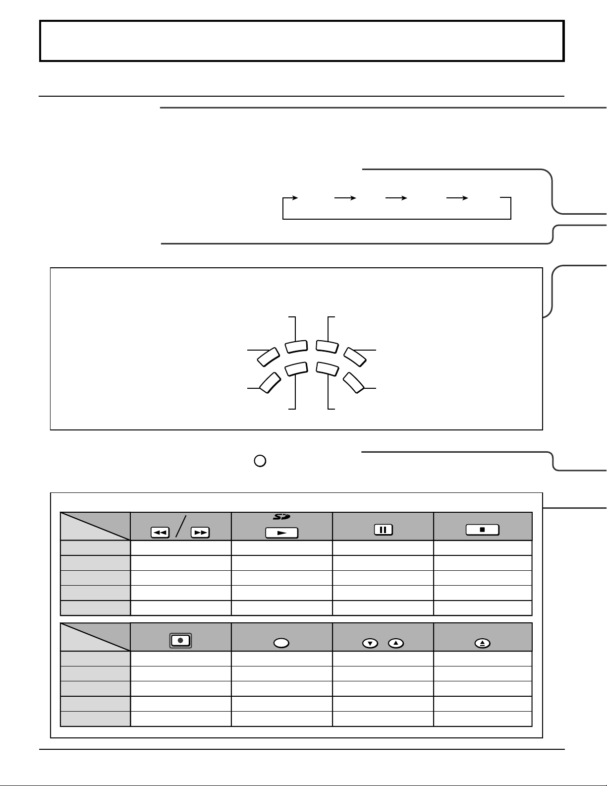
Location of Controls
Illuminated Remote Control
Power button
Press to turn the TV ON or OFF (See page 19).
Note: The TV’s power cord must first be plugged into the wall outlet
and then turned on at the POWER switch (standby mode).
ASPECT button
Change of screen size (See page 52).
JUST 4 : 3
MUTE button
Press this button to mute the sound, press again to cancel the mute.
Mode Selection buttons
Selects the operation mode for the remote control. (See page 63)
Digital Video Disk Mode Selection for Remote Control
AUX
VCR Mode Selection for Remote Control
TV Mode Selection for Remote Control
VCR
TV
DVD
DTV
CBL
Digital TV Mode Selection for Remote Control
R-TUNE
R-TUNE button
Switches to previously viewed channel or video mode.
ZOOM FULL
Aux Mode Selection for Remote Control
RCVR
Receiver/Amplifier Mode Selection
for Remote Control
DBS
Digital Broadcasting Satellite for
Remote Control
Cable TV Mode Selection for Remote Control
Operation of other Device
ButtonsButtons
Device
TV
VCR
CABLE/DBS
DVD/LD/CD
Skip Search REW/FF
RCVR
ButtonsButtons
Device
TV
VCR
CABLE/DBS
DVD/LD/CD
RCVR
22
PIP MIN
REW
PIP MAX
FF
PIP Minimize/Maximize
VCR REW/FF
-
Surround
REC
-
/+
-
VCR RECORD
DBS RECORD
-
-
PLAY
JPEG Viewer
PLAY
-
PLAY
-
FREEZE
TV/VCR
PIP or SPLIT FREEZE
TV/VCR Switch
TV/DBS Switch
-
-
PAUSE
-
Pause
-
Pause
-
PIP CH
VCR CH
PIP or SPLIT CH up/down
VCR CH up/down
TV/DBS CH up/down
-
-
STOP
-
STOP
-
STOP
-
SEARCH
OPEN/CLOSE
PIP Search
-
-
OPEN/CLOSE
-
Page 23
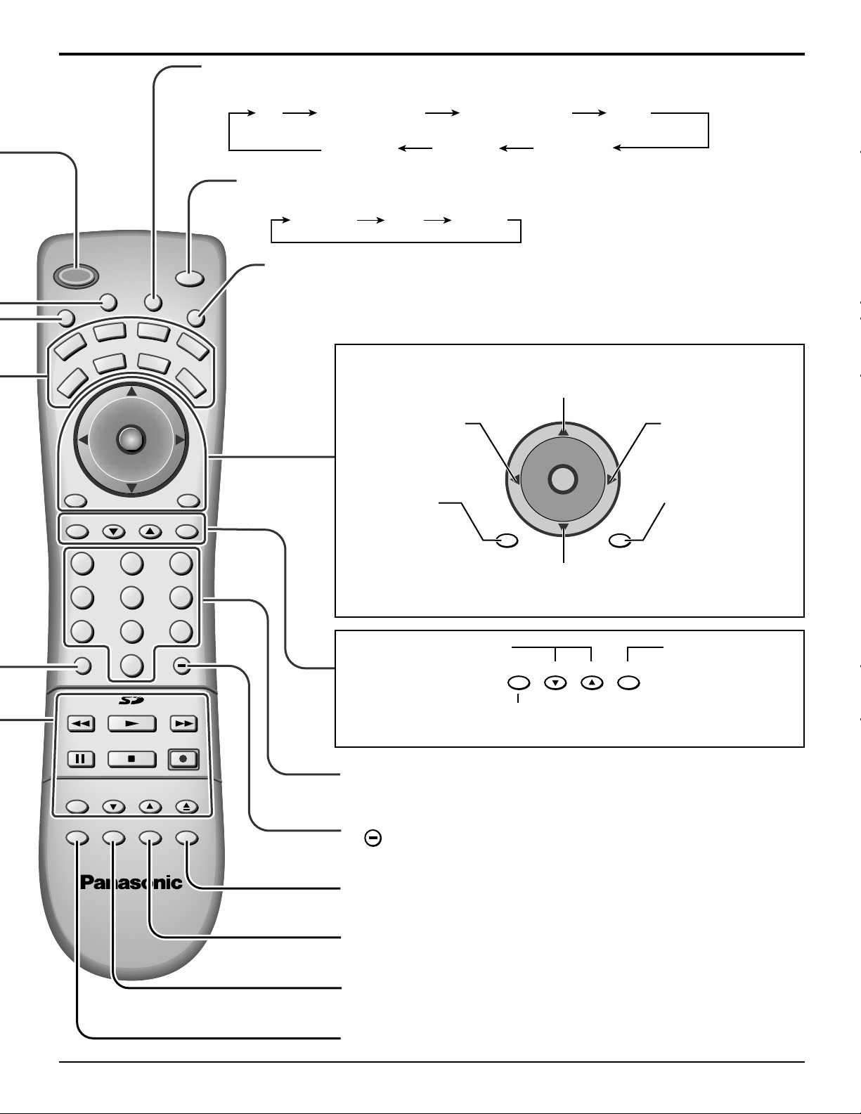
TV/VIDEO button
The input mode changes each time this button is pressed.
Location of Controls
M
POWER
T
U
VCR
PC
MENU
E
TV
A
VOL VOL
T
V
T
/
V
C
E
P
S
VD
D
DTV
I
D
AUX
CBL
CH
O
I
T
N
C
A
CH
PAG EEXIT
123
456
SAP
E
O
RCVR
DBS
RECALL
GUIDE
TV
COMPONENT 1
COMPONENT 2
HDMI
VIDEO 3 VIDEO 1VIDEO 2
SAP button
Selects Audio mode (See page 33).
STEREO SAP MONO
Lights the remote control buttons.
L
I
G
H
T
The selected button blinks when lit.
Changes to the next channel up
Moves cursor upward during menu mode.
Reduces volume
Moves cursor to the
left during menu
mode.
PC menu
Press the “PC”
input mode
selection button to
VOL VOL
PC
MENU
CH
O
I
T
N
C
A
CH
RECALL
Increases volume
Moves cursor to
the right during
menu mode.
Press to display
time, channel,
sleep timer and
other options.
select the PC
input mode.
Changes to the next channel down
Moves cursor downward during menu mode.
7809
R-TUNE PROG
PIP MIN
REW
FREEZE
TV/VCR
PIP SPLIT MOVE SWAP
PLAY
STOPPAUSE
PIP CH
VCR CH
PIP MAX
REC
SEARCH
OPEN/CLOSE
Page up/down for DBS,
skip +/- for DVD & CD.
FF
Returns to normal viewing from the MENU screen.
GUIDEPAG EEXIT
GUIDE button
for DBS.
Previous item in MENU.
Direct program number
selection buttons
PROG
PROG dash button
Program dash channel numbers for DTV and DBS.
Swap pictures in Split Screen and Picture in Picture operation
(See page 48, 51).
Move PIP frame in Picture in Picture Operation (See page 49).
Split Screen (see page 50)
Picture in Picture Operation (see page 48)
23
Page 24

Basic Menu Operations
A
C
T
I
O
N
CH
CH
VOL VOL
PICTURE
PIC MODE
COLOR
TINT
BRIGHTNESS
PICTURE
SHARPNESS
NORMAL
OTHER ADJ.
VIVID
:
EXIT
:
SUB MENU
SET
PICTURE
PIC MODE
COLOR
TINT
BRIGHTNESS
PICTURE
SHARPNESS
NORMAL
OTHER ADJ.
VIVID
PRESS ACTION FOR MAIN MENU
NO
PICTURE
PIC MODE
COLOR
TINT
BRIGHTNESS
PICTURE
SHARPNESS
NORMAL
OTHER ADJ.
PRESS ACTION FOR MAIN MENU
PRESS TO ENTER
PICTURE
PIC MODE
COLOR
TINT
BRIGHTNESS
PICTURE
SHARPNESS
NORMAL
OTHER ADJ.
VIVID
:
EXIT
:
SUB MENU
SET
1
C
A
VOL VOL
2
VOL VOL
[ for OTHER ADJ.]
VOL VOL
CH
CH
Press to display the menu screen.
O
I
T
N
Press to select desired menu icon.
Press to enter submenu field.
PICTURE
PIC MODE
COLOR
TINT
BRIGHTNESS
PICTURE
SHARPNESS
NORMAL
OTHER ADJ.
PRESS ACTION FOR MAIN MENU
VIVID
SET
Press to select desired submenu feature.
CH
O
I
T
N
C
A
CH
Press to select or adjust.
35COLOR
PRESS ACTION TO RETURN
Press to select OTHER ADJ.
CH
O
I
T
N
C
A
CH
Press to enter option menu field.
Proceed to selection and adjustment of
the option menu.
PICTURE
OTHER ADJ.
PRESS ACTION FOR MAIN MENU
COLOR TEMP
NATURAL COLOR
VIDEO NR
3D Y/C FILTER
COLOR MATRIX
VM
FREEZE
COOL
OFF
SPLIT
ON
ON
SD
ON
To return to MAIN MENU: To return to previous screen:
VOL VOL
To end adjustments:
24
CH
O
I
T
N
C
A
CH
Press to return.
PICTURE
PIC MODE
COLOR
TINT
BRIGHTNESS
PICTURE
SHARPNESS
NORMAL
OTHER ADJ.
PRESS ACTION FOR MAIN MENU
VIVID
NO
35COLOR
PRESS ACTION TO RETURN
Press to exit from the MENU screen.
This returns the set to the normal
viewing condition.
NORMAL PICTURE
Page 25
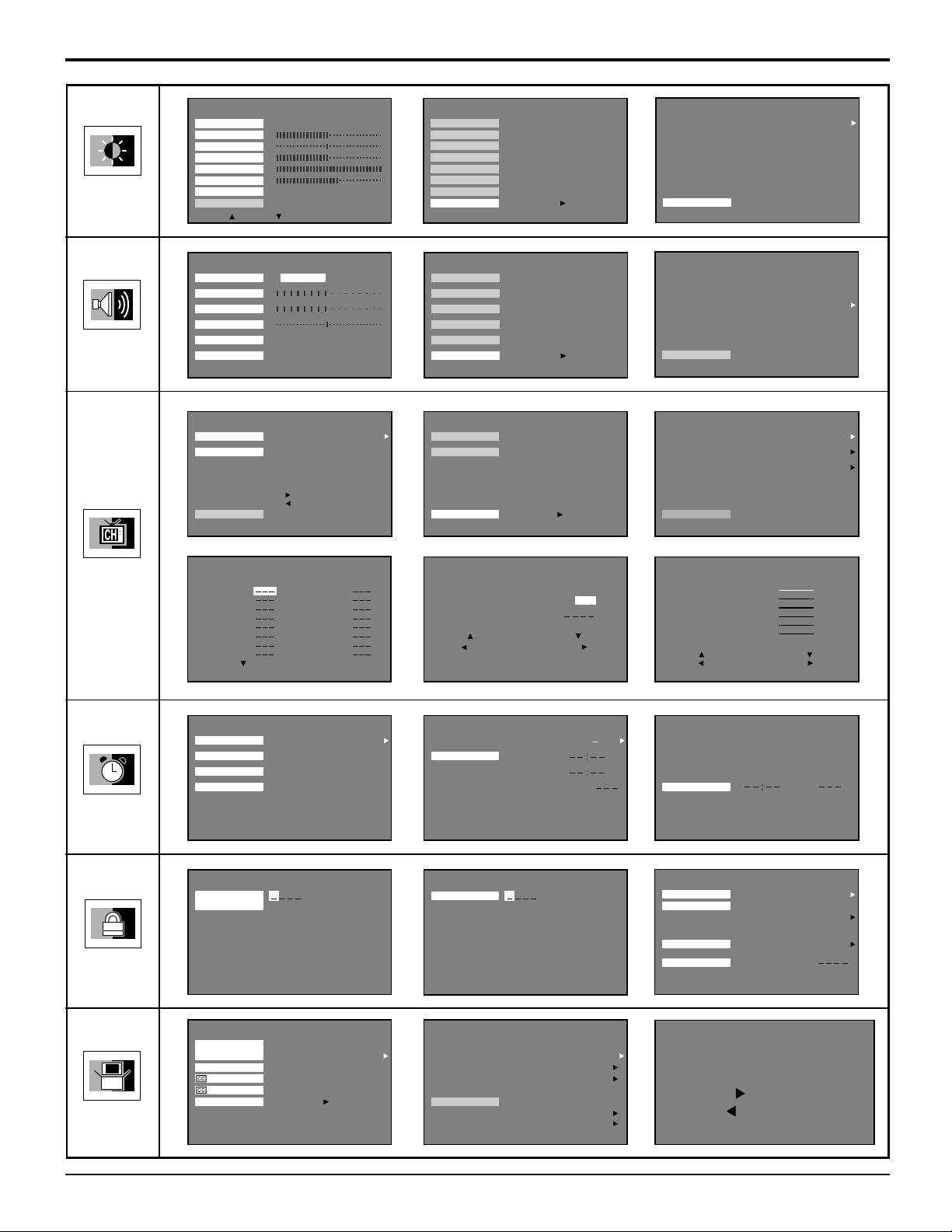
Basic Menu Operations
PICTURE
AUDIO
PICTURE
PIC MODE
COLOR
TINT
BRIGHTNESS
PICTURE
SHARPNESS
NORMAL
OTHER ADJ.
:
AUDIO
MODE
BASS
TREBLE
BALANCE
NORMAL
OTHER ADJ.
PRESS ACTION FOR MAIN MENU
CH. SCAN
FAVORITES
OTHER ADJ.
PRESS ACTION FOR MAIN MENU
:
EXIT
SUB MENU
STEREO SAP MONO
CHANNELS
ENTER CHANNEL 3
FAVORITE CHANNELS
2 5 8 10
18 25
: ADD
: DELETE
VIVID
SET
SET
ALL
PICTURE
PIC MODE
COLOR
TINT
BRIGHTNESS
PICTURE
SHARPNESS
NORMAL
OTHER ADJ.
PRESS ACTION FOR MAIN MENU
AUDIO
MODE
BASS
TREBLE
BALANCE
NORMAL
OTHER ADJ.
OTHEAJ.
PRESS ACTION FOR MAIN MENU
CH. SCAN
FAVORITES
OTHER ADJ.
PRESS ACTION FOR MAIN MENU
PRESS TO ENTER
PRESS TO ENTER
CHANNELS
PRESS TO ENTER
PICTURE
OTHER ADJ.
PRESS ACTION FOR MAIN MENU
OTHER ADJ.
PRESS ACTION TO RETURN
OTHER ADJ.
PRESS ACTION TO RETURN
COLOR TEMP
NATURAL COLOR
VIDEO NR
3D Y/C FILTER
COLOR MATRIX
FREEZE
AUDIO
CHANNELS
HDMI IN
AI SOUND
BBE VIVA 3D
BBE
SURROUND
SPEAKERS
ON
PRESET CAPTION
MANUAL CAPTION
INPUT LABEL
NORMAL
ON
OFF
ON
SD
SPLIT
AUTO
ON
ON
ON
3D
CHANNELS
TIMER
LOCK
CHANNELS
PRESET CAPTION
ABC
CBS
FOX
NBC
PBS
CNN
ESPN
HBO
FOR
PRESS
PRESS ACTION TO RETURN
SLEEP
TIMER1
TIMER2
CLOCK SET
PRESS ACTION FOR MAIN MENU
CREATE
CODE FIRST
PRESS ACTION FOR MAIN MENU
A&E
AMC
BET
BRAVO
CNBC
CNN/SI
COMEDY
COURT
MORE CHANNELS
TIMER
LOCK
NO
CHANNELS
MANUAL CAPTION
ENTER CHANNEL 10
ENTER CAPTION
TO MOVE CURSOR
TO SELECT CHANNEL
PRESS ACTION TO RETURN
TIMER
TIMER1
PRESS ACTION TO RETURN
ENTER CODE
PRESS ACTION FOR MAIN MENU
DAY
ON TIME
OFF TIME
ENTER CHANNEL
SET
LOCK
MON FRI
NO
CHANNELS
INPUT LABEL
COMPONENT1
COMPONENT2
HDMI
VIDEO1
VIDEO2
VIDEO3
TO MOVE CURSOR
TO SELECT LEBEL
PRESS ACTION TO RETURN
TIMER
CLOCK SET
PRESS ACTION TO RETURN
LOCK SET
V - CHIP SET
HOW LONG?
CODE
PRESS ACTION FOR MAIN MANU
BLOCK PROGRAMS :
CHANG CODE
LOCK
U.S. MOVIES
SESTTING:
OFF
12HOURS
SET UP
IDIOMA/
LANGUE
ANTENNA
ON MUTE
MODE
OTHER ADJ.
PRESS ACTION FOR MAIN MENU
PRESS TO ENTER
SET UP
ENGLISH
ANT1
OFF
NO
MODE
AUTO PROGRAM
MANUAL PROGRAM
AUTO POWER ON
OTHER ADJ.
PRESS ACTION TO RETURN
CHAN BANNER
SIDE BAR BRIGHT
POWER SAVE OFF
SET UP
CABLE
OFF
ON
MANUAL PROGRAM
ENTER CHANNEL 3
TO ADD
TO DELETE
PRESS ACTION TO RETURN
25
Page 26
SET UP Operation
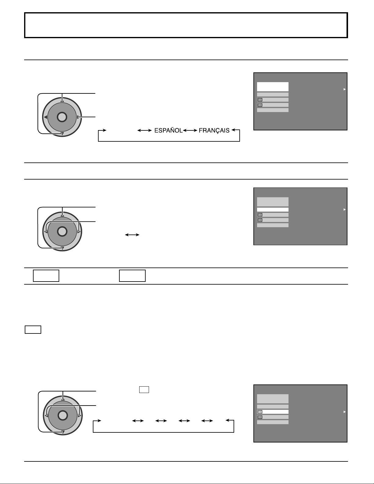
MENU Languages
In SET UP Menu, select IDIOMA / LANGUE to change menu language to
ENGLISH, ESPAÑOL (Spanish) or FRANÇAIS (French).
Press to select IDIOMA / LANGUE.
CH
O
I
T
N
C
A
VOL VOL
CH
ANTENNA Selection
Press to select ENGLISH, SPANISH or FRENCH.
ENGLISH
IDIOMA/
LANGUE
ANTENNA
ON MUTE
MODE
OTHER ADJ.
PRESS ACTION FOR MAIN MENU
SET UP
ENGLISH
ANT1
NO
OFF
To select either ANT1 or ANT2.
Press to select ANTENNA.
cc
CH
O
I
T
N
C
A
VOL VOL
CH
ON MUTE
Press to select ANT1 or ANT2.
ANT1 ANT2
cc
MODE (Closed Captions)
IDIOMA/
LANGUE
ANTENNA
ON MUTE
MODE
OTHER ADJ.
PRESS ACTION FOR MAIN MENU
SET UP
ENGLISH
ANT1
NO
OFF
This receiver has a built in decoder that provides a visual depiction of the audio portion of a television program in the form
of written words across the screen (white or colored letters on a black background). It allows the viewer to read the
dialogue of a television program or other information.
cc ON MUTE
Activates the On-Screen Closed Caption feature, when the MUTE button on the Remote Control is pressed. To deactivate,
press the MUTE button again.
Note:
This feature functions when the Closed Caption Mode is in the “OFF” position. The program being viewed must be
broadcast with Closed Caption.
26
CH
O
I
T
N
C
A
VOL VOL
CH
Press to select cc ON MUTE.
Press to select from the following:
NO (OFF) C1 C2 C3 C4
IDIOMA/
LANGUE
ANTENNA
ON MUTE
MODE
OTHER ADJ.
PRESS ACTION FOR MAIN MENU
SET UP
ENGLISH
ANT1
NO
OFF
Page 27
SET UP Operation
A
C
T
I
O
N
CH
CH
VOL VOL
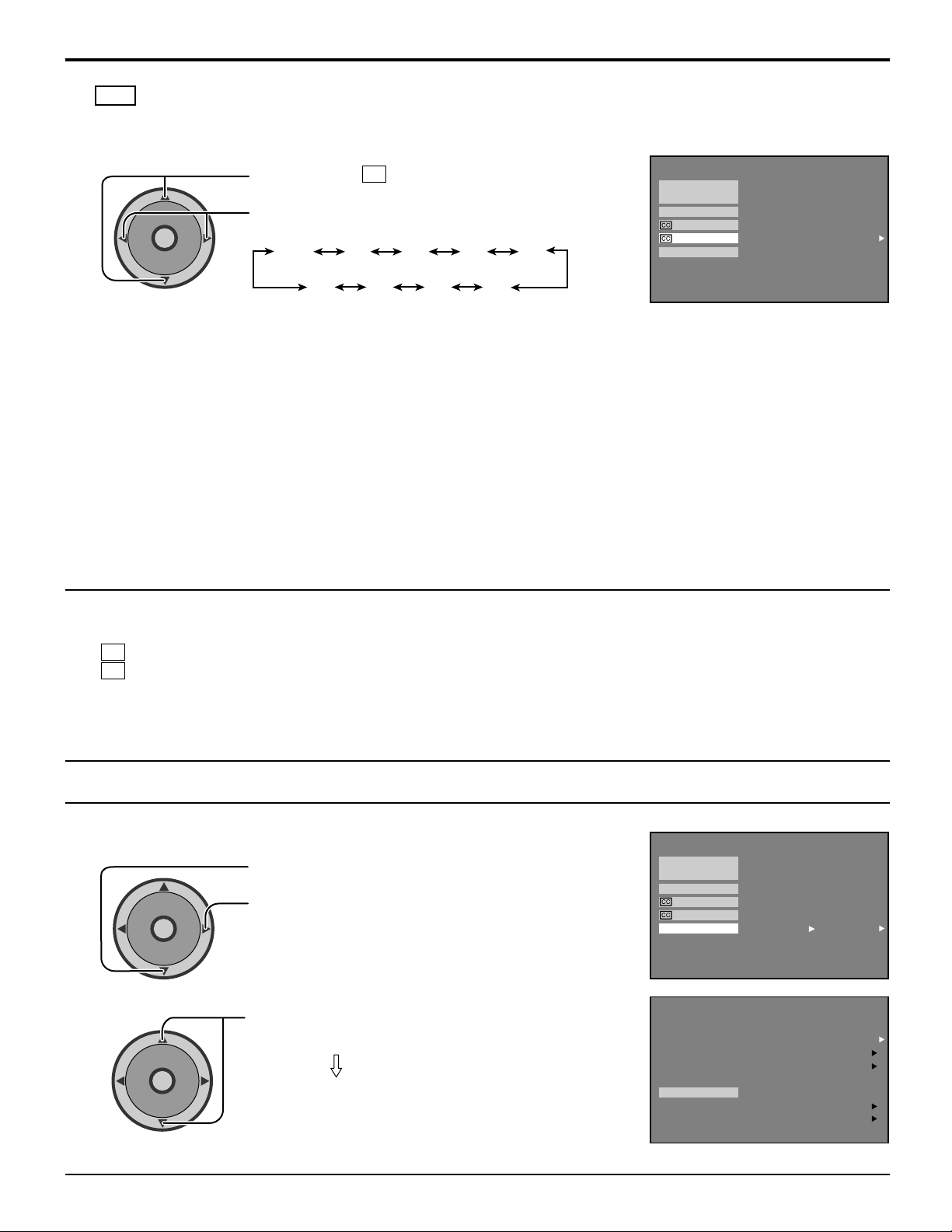
cc MODE
Activates the On-Screen Closed Caption feature. When activated this feature will remain on until OFF is selected in
this menu.
SET UP
ENGLISH
ANT1
NO
OFF
CH
O
I
T
N
C
A
VOL VOL
CH
Press to select cc MODE.
Press to select from the following:
OFF C1 C2 T1
C4T3T4 C3
T2
IDIOMA/
LANGUE
ANTENNA
ON MUTE
MODE
OTHER ADJ.
PRESS ACTION FOR MAIN MENU
• CAPTION OFF -
• CAPTION C1 -
Recommended mode when Closed Caption is not being used.
For video related information that can be displayed (up to 4 lines of script strategically placed on
the television screen so that it does not obstruct relevant parts of the picture).
• CAPTION C2 -
• TEXT T1 -
Another mode used for video related information.
Blanks out a large portion of the picture on the television screen, and displays program guide or
any other information currently being transmitted.
• TEXT T2 -
Another mode which displays information and blanks out a large portion of the picture on the
television screen.
• CAPTION C3 -
• CAPTION C4 -
• TEXT T3 -
Another mode used for video related information.
Another mode used for video related information.
Another mode which displays information and blanks out a large portion of the picture on the
television screen.
• TEXT T4 -
Another mode which displays information and blanks out a large portion of the picture on the
television screen.
Notes:
(1) Recommended menu Set Up for Closed Caption when using Mute Button.
cc ON MUTE: C1
cc MODE: OFF
(2) The setting for CC ON MUTE is valid only when the CC MODE is OFF. CC MODE set to ON will override CC ON MUTE.
This menu cannot be selected when the MAIN picture is displaying a COMPONENT VIDEO INPUT of 480i or more.
(3) When aspect is ZOOM, Closed Caption cannot be used.
To select option menus in OTHER ADJ.
1
2
Selecting option menus in OTHER ADJ.
Press to select OTHER ADJ.
CH
O
I
T
N
C
A
VOL VOL
CH
Press to enter option menu field.
Press to select desired option menu.
Proceed to adjustments.
IDIOMA/
LANGUE
ANTENNA
ON MUTE
MODE
OTHER ADJ.
PRESS ACTION FOR MAIN MENU
OTHER ADJ.
PRESS ACTION TO RETURN
PRESS TO ENTER
MODE
AUTO PROGRAM
MANUAL PROGRAM
AUTO POWER ON
CHAN BANNER
SIDE BAR BRIGHT
POWER SAVE OFF
SET UP
SET UP
CABLE
OFF
ON
27
Page 28
SET UP Operation
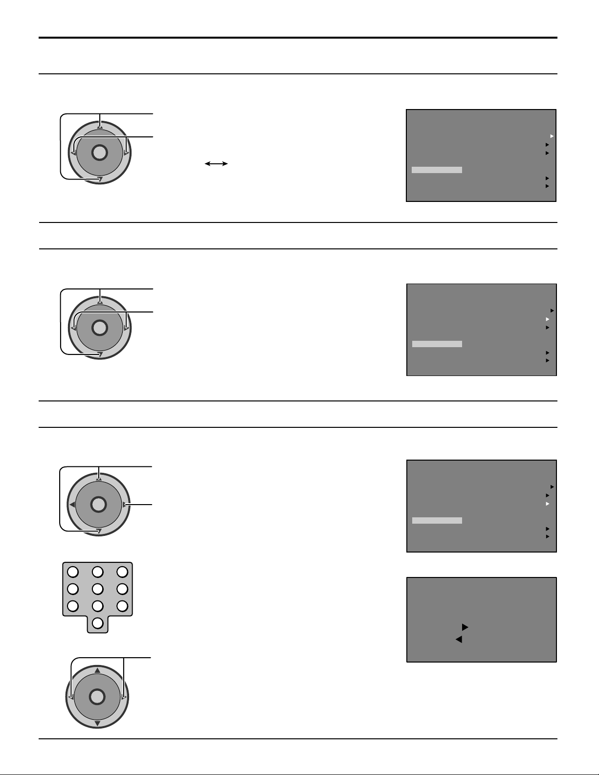
MODE Selection
To select either CABLE or TV.
Press to select MODE.
CH
O
I
T
N
C
A
VOL VOL
CH
Press to select CABLE or TV.
CABLE TV
AUTO PROGRAM
To automatically program all channels with signal.
Press to select AUTO PROGRAM.
CH
O
I
T
N
C
A
VOL VOL
CH
Press to start AUTO PROGRAM.
MODE
AUTO PROGRAM
MANUAL PROGRAM
AUTO POWER ON
OTHER ADJ.
PRESS ACTION TO RETURN
OTHER ADJ.
PRESS ACTION TO RETURN
CHAN BANNER
SIDE BAR BRIGHT
POWER SAVE OFF
MODE
AUTO PROGRAM
MANUAL PROGRAM
AUTO POWER ON
CHAN BANNER
SIDE BAR BRIGHT
POWER SAVE OFF
SET UP
CABLE
OFF
ON
SET UP
CABLE
OFF
ON
MANUAL PROGRAM
To manually add or delete channels.
Press to select MANUAL PROGRAM.
1
2
3
CH
O
I
T
N
C
A
VOL VOL
CH
123
456
7809
CH
O
I
T
N
C
A
VOL VOL
Press to display next menu.
Use remote numeric keypad to select
desired channel.
Press to ADD or DELETE the channel.
MODE CABLE
AUTO PROGRAM
MANUAL PROGRAM
AUTO POWER ON
OTHER ADJ.
PRESS ACTION TO RETURN
ENTER CHANNEL 3
PRESS ACTION TO RETURN
CHAN BANNER
SIDE BAR BRIGHT
POWER SAVE OFF
MANUAL PROGRAM
TO ADD
TO DELETE
SET UP
28
CH
Page 29
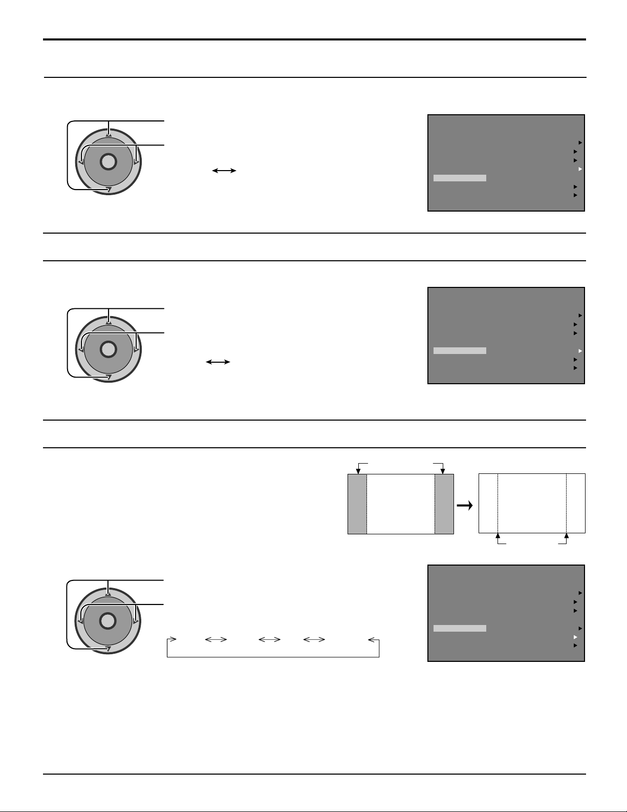
SET UP Operation
AUTO POWER ON
Select SET to power up the TV at the same time as the cable box or other components or select OFF.
Press to select AUTO POWER ON.
CH
O
I
T
N
C
A
VOL VOL
Press to select SET or OFF.
SET OFF
CH
CHAN BANNER
Select ON to display the CHANNEL BANNER on the screen or select OFF.
Press to select CHAN BANNER.
CH
O
I
T
N
C
A
VOL VOL
CH
Press to select ON or OFF.
ON OFF
MODE
AUTO PROGRAM
MANUAL PROGRAM
AUTO POWER ON
OTHER ADJ.
PRESS ACTION TO RETURN
OTHER ADJ.
PRESS ACTION TO RETURN
CHAN BANNER
SIDE BAR BRIGHT
POWER SAVE OFF
MODE
AUTO PROGRAM
MANUAL PROGRAM
AUTO POWER ON
CHAN BANNER
SIDE BAR BRIGHT
POWER SAVE OFF
SET UP
CABLE
SET
ON
SET UP
CABLE
SET
ON
SIDE BAR
Do not display a picture in 4:3 mode for an extended period, as
this can cause an after-image to remain on the side bars on
either side of the display field.
To prevent the appearance of such an after-image, change the
brightness of the side bars.
Press to select the
SIDE BAR.
CH
O
I
T
N
C
A
VOL VOL
CH
Press to select
OFF, DARK, MID, BRIGHT.
OFF DARK MID BRIGHT
Notes:
• Setting the side bar to bright mode for an extended period may result in occurence of after-images.
• The side bar may flash (alternate black/white) depending on the picture being shown on the screen. In such
an occurrence, use the Cinema mode.
side bars
4:3
Screen Display
after-images
MODE
AUTO PROGRAM
MANUAL PROGRAM
AUTO POWER ON
OTHER ADJ.
PRESS ACTION TO RETURN
CHAN BANNER
SIDE BAR
POWER SAVE OFF
SET UP
CABLE
SET
ON
BRIGHT
29
Page 30
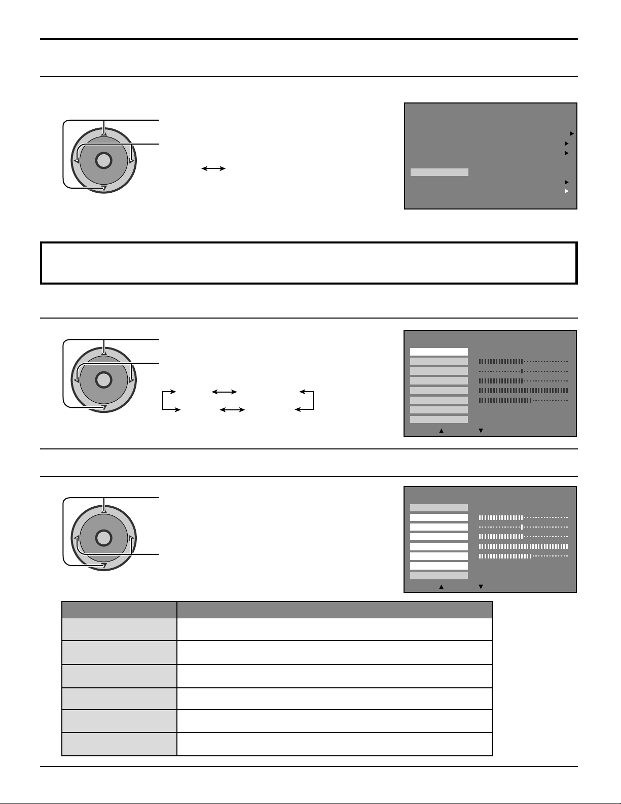
SET UP Operation
POWER SAVE
When this function is turned ON, luminous level of plasma TV is suppressed, so power consumption is reduced.
SET UP
Press to select POWER SAVE.
CH
O
I
T
N
C
A
VOL VOL
CH
Press to select ON or OFF.
ON OFF
OTHER ADJ.
PRESS ACTION TO RETURN
MODE
AUTO PROGRAM
MANUAL PROGRAM
AUTO POWER ON
CHAN BANNER
SIDE BAR BRIGHT
POWER SAVE OFF
PICTURE Adjustment
PICTURE MODE
CABLE
OFF
ON
PICTURE
PIC MODE
COLOR
TINT
BRIGHTNESS
PICTURE
SHARPNESS
NORMAL
OTHER ADJ.
:
EXIT
:
SUB MENU
VIVID
SET
CH
O
I
T
N
C
A
VOL VOL
CH
Press to select PIC MODE.
Press to select your desired PICTURE MODE.
VIVID
AUTO
STANDARD
CINEMA
COLOR / TINT / BRIGHTNESS / PICTURE / SHARPNESS / NORMAL
PICTURE
PIC MODE
COLOR
TINT
BRIGHTNESS
PICTURE
SHARPNESS
NORMAL
OTHER ADJ.
:
EXIT
:
SUB MENU
VIVID
SET
C
A
VOL VOL
COLOR
CH
CH
I
T
O
N
Item
Press to select each submenu (COLOR / TINT /
BRIGHTNESS / PICTURE / SHARPNESS /
NORMAL).
Press to adjust the desired level by looking at the
picture behind the menu.
Function
Adjusts desired color intensity.
TINT
BRIGHTNESS
PICTURE
SHARPNESS
NORMAL
30
Adjusts natural flesh tones.
Adjusts dark areas of picture.
Adjusts white areas of picture.
Adjusts clarity of outline detail.
Resets all picture adjustments to factory default settings.
Page 31
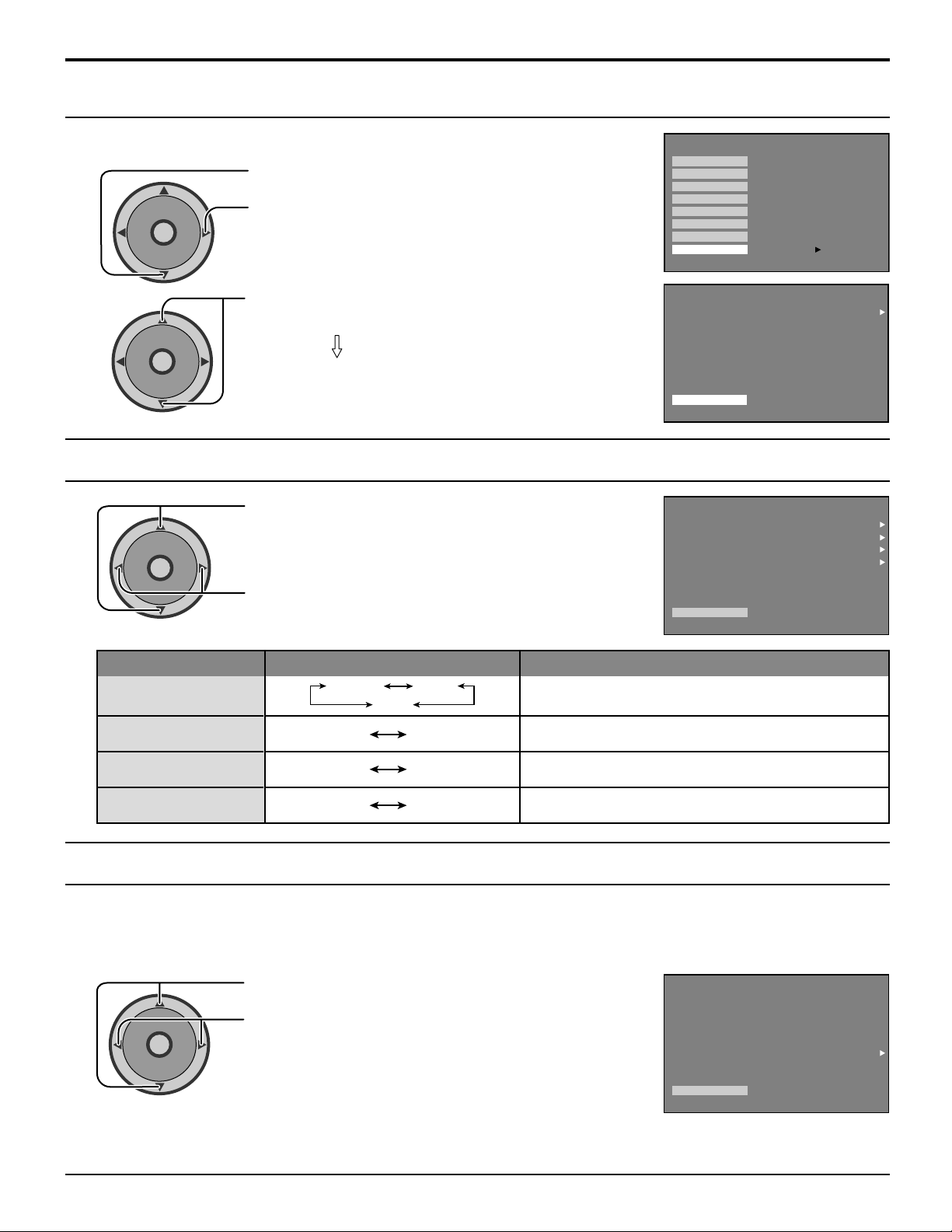
Selecting option menus in OTHER ADJ.
A
C
T
I
O
N
CH
CH
VOL VOL
PICTURE
PIC MODE
COLOR
TINT
BRIGHTNESS
PICTURE
SHARPNESS
NORMAL
OTHER ADJ.
PRESS ACTION FOR MAIN MENU
PRESS TO ENTER
To select option menus in OTHER ADJ.
PICTURE Adjustment
1
Press to select OTHER ADJ.
2
CH
O
I
T
N
C
A
VOL VOL
CH
Press to enter option menu field.
Press to select desired option menu.
Proceed to adjustments.
PICTURE
COLOR TEMP
NATURAL COLOR
VIDEO NR
3D Y/C FILTER
COLOR MATRIX
FREEZE
OTHER ADJ.
PRESS ACTION FOR MAIN MENU
COLOR TEMP (Temperature) / NATURAL COLOR / VIDEO NR / 3D Y/C FILTER
CH
O
I
T
N
C
A
VOL VOL
CH
Press to select each option menu (COLOR TEMP
/ NATURAL COLOR / VIDEO NR / 3D Y/C FILTER).
Press to adjust the desired level by looking at the
picture behind the menu.
PICTURE
COLOR TEMP
NATURAL COLOR
VIDEO NR
3D Y/C FILTER
COLOR MATRIX
FREEZE
OTHER ADJ.
PRESS ACTION FOR MAIN MENU
NORMAL
ON
OFF
ON
SD
SPLIT
NORMAL
ON
OFF
ON
SD
SPLIT
COLOR TEMP
(temperature)
NATURAL COLOR
VIDEO NR
3D Y/C FILTER
COLOR MATRIX
Displays input signals (480p signals) in a natural color from digital equipment adaptors connected to COMPONENT VIDEO
INPUT (Y, Pb/Cb ,Pr/Cr input terminals).
Select HD or SD to automatically adjust color parameters for HD (high definition) and SD (standard definition).
CH
I
T
C
A
VOL VOL
CH
Note:
(1) When viewing a non-standard DTV signal format, you can change color parameters manually for the best picture quality.
(2)
COLOR MATRIX does not need to be set when using High-Definition equipment or 480i output equipment. Use only for 480p signal source.
Item
O
N
Mode
NORMAL WARM
COOL
ON OFF
ON OFF
ON OFF
To increase or decrease WARM (red) and COOL
(blue) colors to suit personal preferences.
To increase the color reproduction range with natural
color gradation and highly delicate hues.
Reduces noise in the channel,commonly called
snow. Remains off when receiving a strong signal.
Minimizes noise and cross color in the picture.
Press to select COLOR MATRIX.
Press to select SD or HD.
SD : When the input signal is a normal TV
system (NTSC).
HD : When the input signal is a High-Definition
system (ATSC).
Explanations
PICTURE
COLOR TEMP
NATURAL COLOR
VIDEO NR
3D Y/C FILTER
COLOR MATRIX
FREEZE
OTHER ADJ.
PRESS ACTION FOR MAIN MENU
NORMAL
ON
OFF
ON
SD
SPLIT
31
Page 32
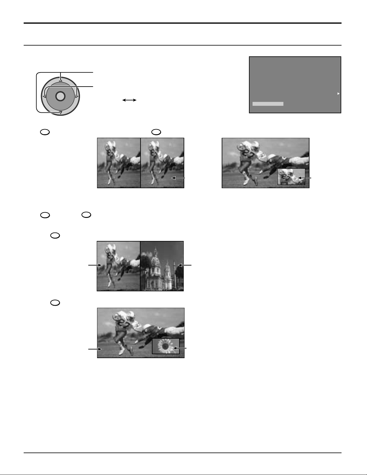
PICTURE Adjustment
FREEZE
Select SPLIT or PIP to determine the frozen picture frame during single screen.
1
2
VOL VOL
FREEZE
TV/VCR
CH
O
I
T
N
C
A
CH
When the screen is single press
Press to select FREEZE.
Press to select SPLIT or PIP.
SPLIT PIP
FREEZE
TV/VCR
to freeze the screen.
FREEZE
When FREEZE SPLIT is selected. When FREEZE PIP is selected.
FREEZE
TV/VCR
Press
again to recover.
is pressed during Split Screen, the Split Screen will be frozen and the main picture continues action (see page 50).
3
Notes:
(1)
When
FREEZE
TV/VCR
FREEZE
TV/VCR
PICTURE
COLOR TEMP
NATURAL COLOR
VIDEO NR
3D Y/C FILTER
COLOR MATRIX
FREEZE
OTHER ADJ.
PRESS ACTION FOR MAIN MENU
FREEZE
NORMAL
ON
OFF
ON
SD
SPLIT
Main Picture
Split Screen
(FREEZE)
FREEZE
When
TV/VCR
is pressed during PIP Operation, the PIP frame will be frozen and the main picture continues action (see page 49).
Main Picture
PIP frame
(2)
(FREEZE)
Notes:
(1) The frozen screen will be recovered automatically after 3 minutes.
(2) When it operates ASPECT with PIP operation, it cancels freeze condition in PIP frame.
32
Page 33
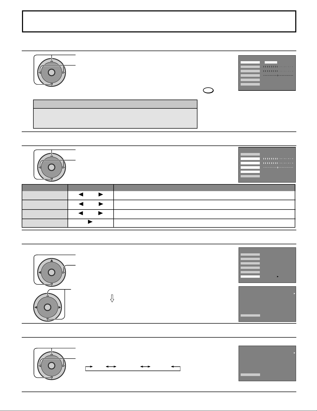
Audio Adjustment
A
C
T
I
O
N
CH
CH
VOL VO L
Selecting STEREO/SAP/MONO
Press to select MODE.
CH
O
I
T
N
C
A
VOL VO L
CH
Press to select STEREO / SAP / MONO.
Red display - Signal available
White display - Signal not available
Note:
AUDIO MODE selection is also possible by pressing the
SAP
MODE
BASS
TREBLE
BALANCE
NORMAL
OTHER ADJ.
button on the remote control (see page 23).
Helpful Hints:
STEREO - Two channel Audio reception.
•
SAP - Second Audio Programming (typically used for bilingual audio).
•
MONO - Use when stereo signal is weak.
•
Selecting BASS / TREBLE / BALANCE / NORMAL
CH
O
I
T
C
A
VOL VO L
CH
Item
BASS
TREBLE
BALANCE
NORMAL
Press to select BASS / TREBLE / BALANCE / NORMAL.
N
Press to adjust the desired level by listening to the sound.
Effect Function
Less More
Less More
Left SP. Right SP.
NO
Increase or decrease the bass response.
Increase or decrease the treble response.
Emphasize the left / right speaker volume.
Reset BASS, TREBLE and BALANCE adjustments to factory default settings.
MODE
BASS
TREBLE
BALANCE
NORMAL
OTHER ADJ.
AUDIO
STEREO SAP MONO
PRESS ACTION FOR MAIN MENU
AUDIO
STEREO SAP MONO
PRESS ACTION FOR MAIN MENU
SET
SET
Selecting option menus in OTHER ADJ.
To select option menus in OTHER ADJ.
Press to select OTHER ADJ.
1
CH
O
I
T
N
C
A
VOL VO L
CH
Press to enter option menu field.
Press to select desired option menu.
2
Proceed to adjustments.
HDMI IN
HDMI IN
Perform input switching of analog audio input (for DVI) and digital audio input (for HDMI) when using the HDMI terminal.
Press to select HDMI IN.
CH
O
I
T
N
C
A
VOL VO L
CH
Press to select your desired mode.
ANALOGDIGITALAUTO
AUTO : Automatically performs digital/analog input switching according to the input signal type.
DIGITAL : Forces use of digital audio input signal transmitted via the HDMI terminal.
ANALOG : Forces use of analog audio input signal transmitted via separate RCA terminals.
AUDIO
MODE
BASS
TREBLE
BALANCE
NORMAL
OTHER ADJ.
OTHEAJ.
PRESS ACTION FOR MAIN MENU
OTHER ADJ.
PRESS ACTION TO RETURN
OTHER ADJ.
PRESS ACTION TO RETURN
AUDIO
AUDIO
PRESS TO ENTER
HDMI IN
AI SOUND
BBE VIVA 3D
BBE
SURROUND
SPEAKERS
ON
HDMI IN
AI SOUND
BBE VIVA 3D
BBE
SURROUND
SPEAKERS
ON
AUTO
ON
OFF
OFF
OFF
AUTO
ON
OFF
OFF
OFF
33
Page 34
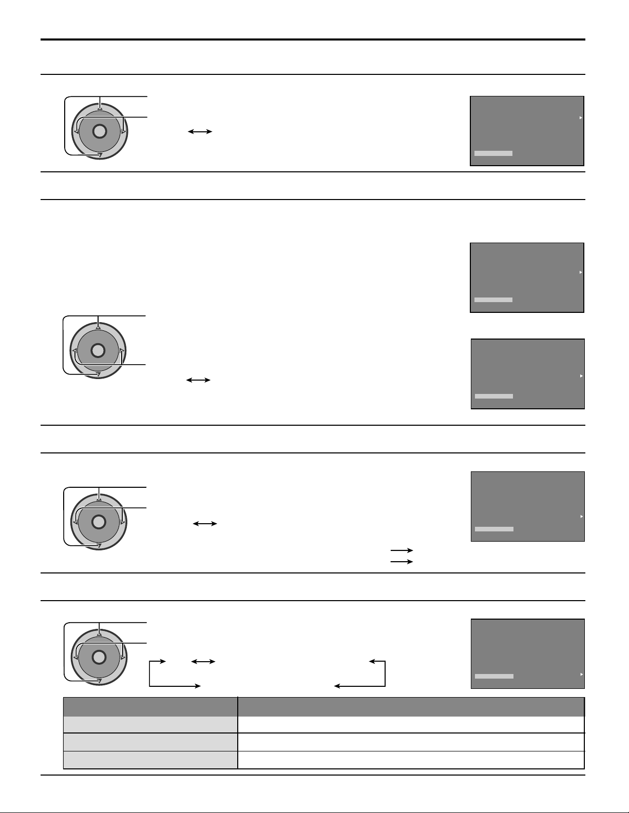
Audio Adjustment
AI SOUND
AI SOUND Equalize overall volume levels across all channels.(AI sound is not available in VIDEO mode).
CH
O
I
T
N
C
A
VOL VO L
CH
Press to select AI SOUND.
Press to select ON or OFF.
ON OFF
Note: Al SOUND is not available in VIDEO mode.
AUDIO
HDMI IN
AI SOUND
BBE VIVA 3D
BBE
SURROUND
SPEAKERS
OTHER ADJ.
PRESS ACTION TO RETURN
ON
AUTO
OFF
OFF
OFF
ON
BBE VIVA / BBE
The distinguishing feature of BBE VIVA is its maintenance of accurate audio imagery. Ordinary 3D surround systems force the
sound out to the left and right, affecting the center channel. As a result it may become hard to hear people's voices, or the center
audio may completely disappear. BBE VIVA reproduces vocals in music and voices in movies accurately and distinctly.
BBE VIVA This maintains a constant level of sound that is faithful to the original, producing
Hi-Fi 3D sound that cannot be obtained with other types of 3D Surround.
BBE Use special signal processing to accurately reproduce the "attack" of each
sound, in order to make it immediate and superbly faithful to the original,
while retaining its natural feel.
Press to select BBE VIVA [ With BBE VIVA Version]
CH
O
I
T
N
C
A
VOL VO L
CH
or BBE [ No BBE VIVA Version].
Press to select ON or OFF.
ON OFF
Notes:
• When “BBE VIVA” is set to ON, “BBE” and “SURROUND” setting are fixed to ON.
• When “BBE VIVA” is set to OFF, “BBE” and “SURROUND” can be set individually.
AUDIO
HDMI IN
AI SOUND
BBE VIVA 3D
BBE
SURROUND
SPEAKERS
OTHER ADJ.
PRESS ACTION TO RETURN
ON
AUTO
[ With BBE VIVA Version]
AUDIO
HDMI IN
AI SOUND
BBE VIVA 3D
BBE
SURROUND
SPEAKERS
OTHER ADJ.
PRESS ACTION TO RETURN
ON
AUTO
[ No BBE VIVA Version]
ON
ON
ON
OFF
OFF
OFF
3D
ON
SURROUND
To enjoy a concert hall effect, turn the SURROUND to ON.
SURROUND function is effective when BBE VIVA is set to OFF.
Press to select SURROUND.
CH
O
I
T
N
C
A
VOL VO L
CH
Press to select ON or OFF.
ON OFF
Notes:
When a stereo signal is available : SURROUND set to ON.
When audio signal is monoural : SURROUND set to OFF.
SPEAKERS
Select the desired SPEAKER mode.
Press to select SPEAKERS.
CH
O
I
T
N
C
A
VOL VO L
CH
ON
OFF & Variable Audio Out
Press to select your desired mode.
ON OFF & VARIABLE AUDIO OUT
OFF & FIXED AUDIO OUT
Mode Function
TV speakers operate normally.
TV speakers off -audio adjustable by television.
AUDIO
HDMI IN
AI SOUND
BBE VIVA 3D
BBE
SURROUND
SPEAKERS
AUDIO
ON
HDMI IN
AI SOUND
BBE VIVA 3D
BBE
SURROUND
SPEAKERS
ON
OTHER ADJ.
PRESS ACTION TO RETURN
OTHER ADJ.
PRESS ACTION TO RETURN
AUTO
OFF
OFF
OFF
AUTO
OFF
OFF
OFF
ON
ON
OFF & Fixed Audio Out
34
TV speakers off -audio adjustable by the external amplifier only.
Page 35
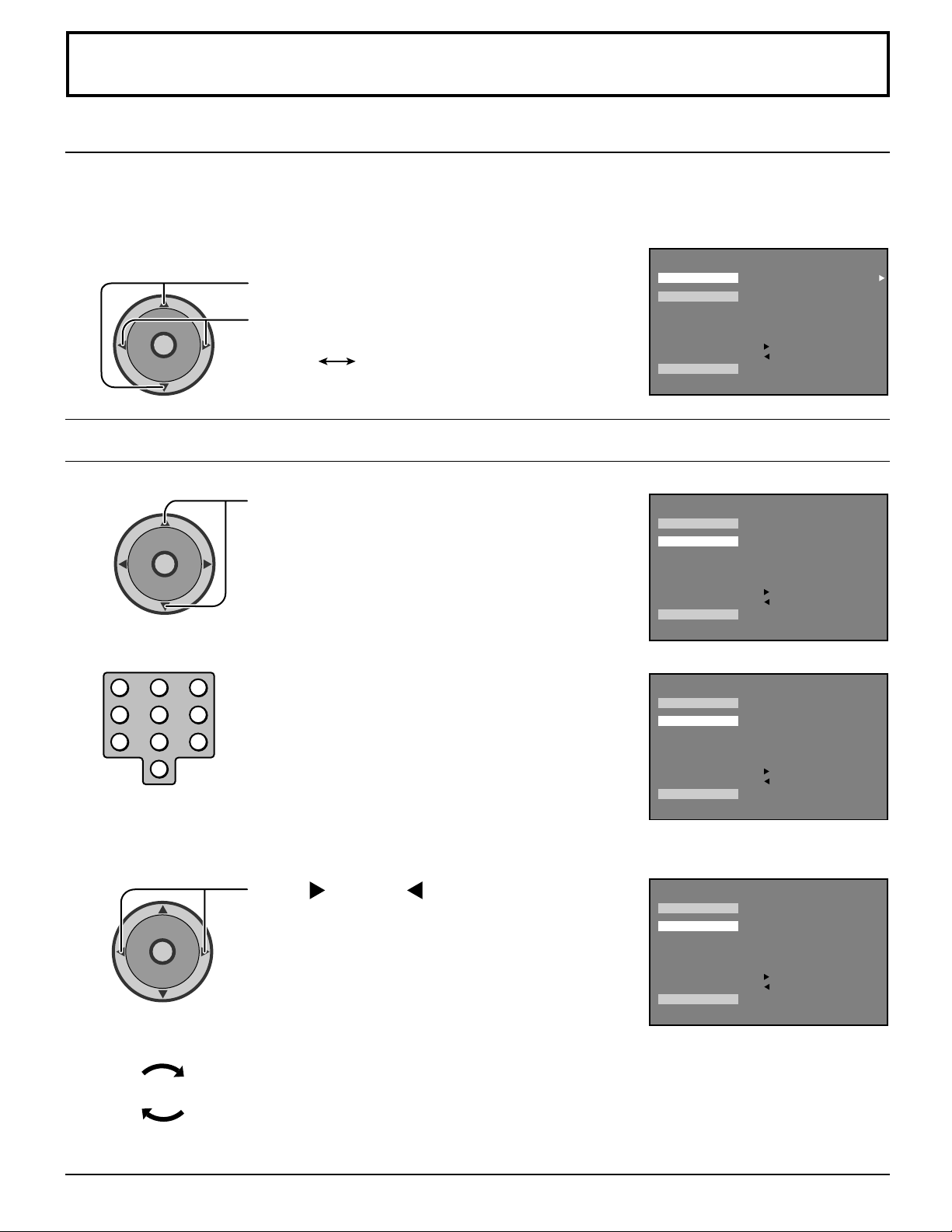
CHANNELS Adjustment
CHANNEL SCAN
Let you select the channel scanning mode either FAV or ALL.
CHANNEL SCAN FAV To enter up to 16 favorite channels.
CHANNEL SCAN ALL To scan all channels when using the CH up/down buttons.
Press to select CH. SCAN.
CH
O
I
T
N
C
A
VOL VOL
CH
FAVORITE CHANNELS Selection
Press to select FAV or ALL.
FAV ALL
CHANNELS
CH. SCAN
FAVORITES
OTHER ADJ.
PRESS ACTION FOR MAIN MENU
ENTER CHANNEL 3
FAVORITE CHANNELS
2 5 8 10
18 25
: ADD
: DELETE
ALL
1
2
3
CH
O
I
T
N
C
A
VOL VOL
CH
123
456
7809
CH
O
I
T
N
C
A
VOL VOL
CH
Press to select FAVORITES.
Use remote numeric keypad to select desired
channel.
Press to add or to delete the selected
channel.
CHANNELS
CH. SCAN
FAVORITES
OTHER ADJ.
PRESS ACTION FOR MAIN MENU
CH. SCAN
FAVORITES
OTHER ADJ.
PRESS ACTION FOR MAIN MENU
ENTER CHANNEL 3
FAVORITE CHANNELS
2 5 8 10
18 25
: ADD
: DELETE
CHANNELS
ENTER CHANNEL 15
FAVORITE CHANNELS
2 5 8 10
18 25
: ADD
: DELETE
ALL
ALL
(Example: Channel 15 is selected)
CHANNELS
CH. SCAN
FAVORITES
OTHER ADJ.
PRESS ACTION FOR MAIN MENU
ENTER CHANNEL 15
FAVORITE CHANNELS
2 5 8 10
15 18 25
: ADD
: DELETE
ALL
(Example: Channel 15 is added)
4
23
Repeat step 2 to 3 up to 16 favorite channels.
35
Page 36
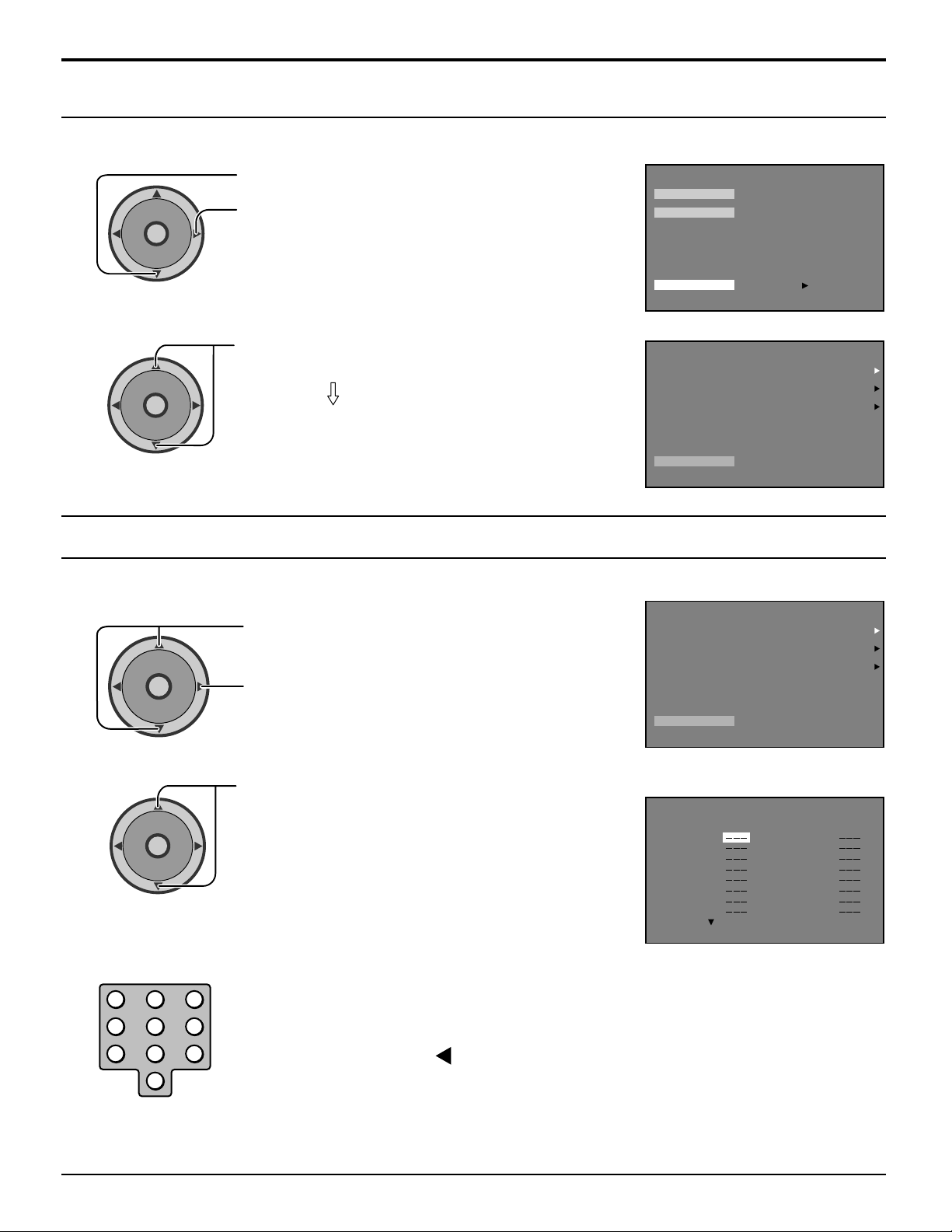
CHANNELS Adjustment
A
C
T
I
O
N
CH
CH
VOL VOL
Selecting option menus in OTHER ADJ.
To select option menus in OTHER ADJ.
1
CH
O
I
T
N
C
A
VOL VOL
CH
Press to select OTHER ADJ.
Press to enter option menu field.
Press to select desired option menu.
2
Proceed to adjustments.
PRESET CAPTION
Assign channel numbers to pre-set popular TV stations.
1
CH
O
I
T
N
C
A
VOL VOL
Press to select PRESET CAPTION.
Press to display next menu.
CHANNELS
CH. SCAN
FAVORITES
OTHER ADJ.
PRESS ACTION FOR MAIN MENU
OTHER ADJ.
PRESS ACTION TO RETURN
PRESS TO ENTER
CHANNELS
PRESET CAPTION
MANUAL CAPTION
INPUT LABEL
CHANNELS
PRESET CAPTION
MANUAL CAPTION
INPUT LABEL
2
3
36
CH
CH
O
I
T
N
C
A
VOL VOL
CH
123
456
7809
Press to select desired PRESET CAPTION.
Use remote numeric keypad to select desired
channel (refer to your local TV guide).
Note:
To delete a channel, press VOL while channel is
highlighted.
OTHER ADJ.
PRESS ACTION TO RETURN
CHANNELS
PRESET CAPTION
ABC
CBS
FOX
NBC
PBS
CNN
ESPN
HBO
FOR
PRESS
PRESS ACTION TO RETURN
MORE CHANNELS
A&E
AMC
BET
BRAVO
CNBC
CNN/SI
COMEDY
COURT
Page 37
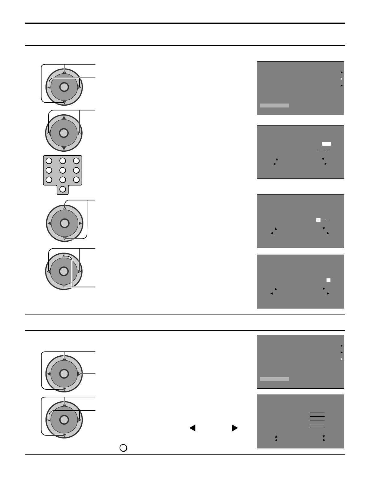
MANUAL CAPTION
123
456
7809
A
C
T
I
O
N
CH
CH
VOL VOL
Enter channel numbers and captions manually.
1
2
CH
O
I
T
N
C
A
VOL VOL
CH
CH
O
I
T
N
C
A
VOL VOL
CH
Press to select MANUAL CAPTION.
Press to display next menu.
Press to enter desired channel.
OR
Use remote numeric keypad to select desired
channel (refer to your local TV guide).
CHANNELS Adjustment
CHANNELS
PRESET CAPTION
MANUAL CAPTION
INPUT LABEL
OTHER ADJ.
PRESS ACTION TO RETURN
CHANNELS
MANUAL CAPTION
ENTER CHANNEL 10
ENTER CAPTION
TO MOVE CURSOR
TO SELECT CHANNEL
PRESS ACTION TO RETURN
3
4
CH
O
I
T
N
C
A
VOL VOL
CH
Press to select ENTER CAPTION.
Press to select characters.
Press to move cursor.
Note:
Repeat Step 4 up to 4 characters.
In MANUAL CAPTION up to 4 characters can be selected as a CAPTION.
INPUT LABEL
Label video input connections to display optional equipment.
Press to select INPUT LABEL.
1
CH
O
I
T
N
C
A
VOL VOL
CH
Press to display next menu.
CHANNELS
MANUAL CAPTION
ENTER CHANNEL 10
ENTER CAPTION
TO MOVE CURSOR
TO SELECT CHARACTER
PRESS ACTION TO RETURN
CHANNELS
MANUAL CAPTION
ENTER CHANNEL 10
ENTER CAPTION : / 5 A
TO MOVE CURSOR
TO SELECT CHARACTER
PRESS ACTION TO RETURN
CHANNELS
PRESET CAPTION
MANUAL CAPTION
INPUT LABEL
OTHER ADJ.
PRESS ACTION TO RETURN
2
CH
O
I
T
N
C
A
VOL VOL
CH
Press to move cursor.
Press to select desired LABEL.
Note:
To skip, select LABEL, then press VOL or VOL to
select ‘‘SKIP’’. The selected INPUT mode will be skipped
TV/VIDEO
when
button is pressed.
CHANNELS
INPUT LABEL
COMPONENT1
COMPONENT2
HDMI
VIDEO1
VIDEO2
VIDEO3
TO MOVE CURSOR
TO SELECT LEBEL
PRESS ACTION TO RETURN
VCR
37
Page 38
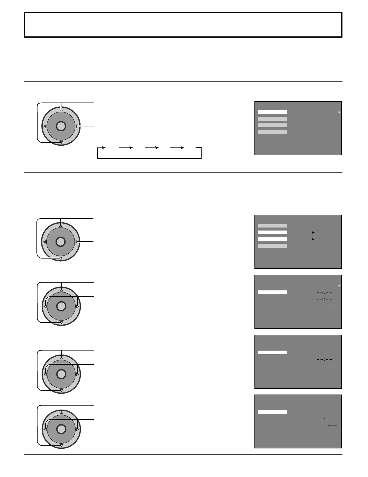
TIMER
The TIMER can switch the TV ON or OFF. Before attempting TIMER1 and TIMER2 confirm the CLOCK SET and adjust if
necessary. Then set TIMER1 and TIMER2.
SLEEP
SLEEP sets the sleep time.
CH
O
I
T
N
C
A
VOL VOL
CH
Press to select SLEEP.
Press to select the desired sleep time.
To turn off the timer select NO.
NO 30 60 90
SLEEP
TIMER1
TIMER2
CLOCK SET
PRESS ACTION FOR MAIN MENU
TIMER
NO
TIMER1 and TIMER2
In TIMER menu, select one or both timers to turn the television on and off at selected times, on selected channels, and on
selected days.TIME must be entered in CLOCK SET to operate the TIMER features.
VOL VOL
DAY
VOL VOL
Press to select TIMER1 or TIMER2.
CH
O
I
T
N
C
A
Press to enter.
CH
Set the day of the week.
Press to select DAY.
CH
O
I
T
N
C
A
CH
Press to set the day of the week.
(select day or days)
SLEEP
TIMER1
TIMER2
CLOCK SET
PRESS ACTION FOR MAIN MENU
TIMER1
PRESS ACTION TO RETURN
TIMER
PRESS TO ENTER
PRESS TO ENTER
TIMER
DAY
ON TIME
OFF TIME
ENTER CHANNEL
SET
MON FRI
NO
ON TIME
1
2
38
CH
O
I
T
N
C
A
VOL VOL
CH
CH
O
I
T
N
C
A
VOL VOL
CH
Set the time of day.
Press to select ON TIME.
Press to set hours AM or PM.
Press to move to minutes position.
Press to set minutes.
TIMER
DAY
TIMER1
PRESS ACTION TO RETURN
TIMER1
PRESS ACTION TO RETURN
ON TIME
OFF TIME
ENTER CHANNEL
SET
TIMER
DAY
ON TIME
OFF TIME
ENTER CHANNEL
SET
MON FRI
1 2 : 0 0 PM
NO
MON FRI
1 2 : 0 0 PM
NO
Page 39
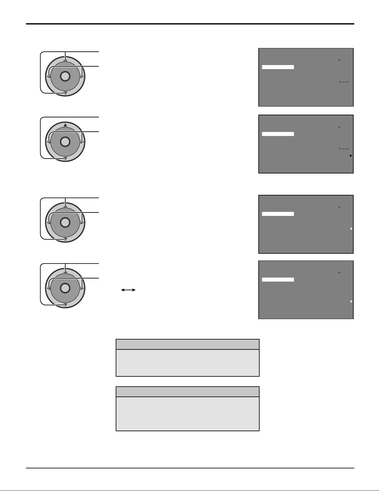
TIMER
OFF TIME
1
CH
O
I
T
N
C
A
VOL VOL
CH
2
CH
O
I
T
N
C
A
VOL VOL
CH
ENTER CHANNEL
1
CH
O
I
T
N
C
A
VOL VOL
CH
Set the time of day.
Press to select OFF TIME.
Press to set hours AM or PM.
Press to move to minutes position.
Press to set minutes.
Press to select ENTER CHANNEL.
Press to select channel.
TIMER
DAY
TIMER1
PRESS ACTION TO RETURN
TIMER1
PRESS ACTION TO RETURN
TIMER1
ON TIME
OFF TIME
ENTER CHANNEL
SET
TIMER
DAY
ON TIME
OFF TIME
ENTER CHANNEL
SET
TIMER
DAY
ON TIME
OFF TIME
ENTER CHANNEL
SET
MON FRI
1 2 : 0 0 PM
1 3 : 0 0 PM
NO
MON FRI
1 2 : 0 0 PM
1 3 : 0 0 PM
NO
MON FRI
1 2 : 0 0 PM
1 3 : 0 0 PM
5
NO
2
CH
O
I
T
N
C
A
VOL VOL
CH
Press to select SET.
Press to select YES.
NOYES
TIMER Activation
The TIMER is active when the television is OFF or
ON. The television will switch to the selected
channel at the selected time set in the TIMER.
Turn Off After 90 Minutes
The television automatically turns OFF after 90
minutes when turned ON by the TIMER. If the OFF
time is selected or if a key is pressed, the automatic
OFF after 90 minutes will be cancelled.
PRESS ACTION TO RETURN
TIMER
DAY
TIMER1
PRESS ACTION TO RETURN
ON TIME
OFF TIME
ENTER CHANNEL
SET
MON FRI
1 2 : 0 0 PM
1 3 : 0 0 PM
5
NO
Notes:
(1) When the power to the TV set is disrupted due to a power outage or similar problem, after power is restored, the off-
timer will be deactivated and the TV will be in standby mode.
(2) To see the remaining sleep time, press the RECALL button.
39
Page 40
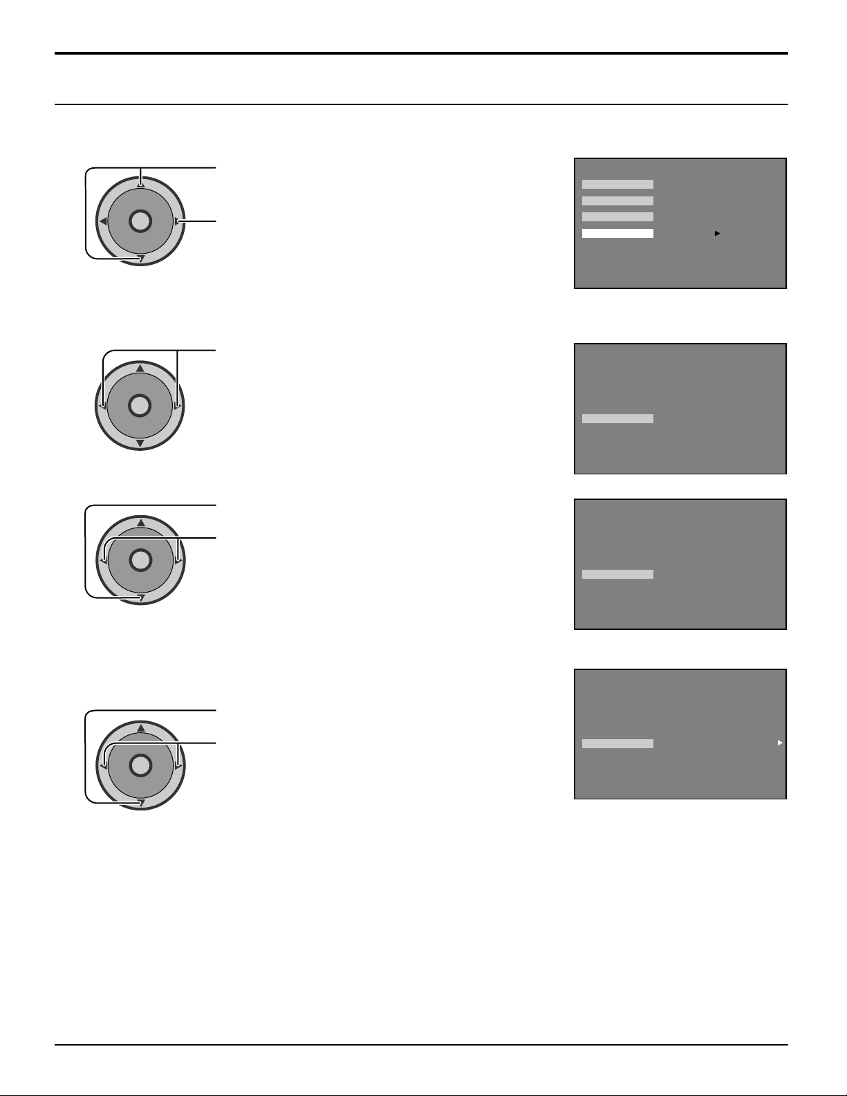
TIMER
CLOCK SET
CLOCK SET sets the present time. This is necessary to operate the TIMER features.
1
2
3
VOL VOL
TIME
VOL VOL
VOL VOL
CH
O
I
T
N
C
A
CH
Set the time of day.
CH
O
I
T
N
C
A
CH
CH
O
I
T
N
C
A
CH
Press to select CLOCK SET.
Press to enter.
Press to set hours AM or PM.
Press to move to minutes position.
Press to set minutes.
TIMER
SLEEP
TIMER1
TIMER2
CLOCK SET
PRESS ACTION FOR MAIN MENU
CLOCK SET
PRESS ACTION TO RETURN
CLOCK SET
PRESS TO ENTER
TIMER
1 2 : 0 0 AM SUN
TIMER
1 2 : 3 0 PM SUN
4
DAY
Set the day of the week.
CH
O
I
T
N
C
A
VOL VOL
CH
Press to move to DAY position.
Press to select the day of the week.
PRESS ACTION TO RETURN
TIMER
CLOCK SET
PRESS ACTION TO RETURN
1 2 : 3 0 PM SUN
40
Page 41
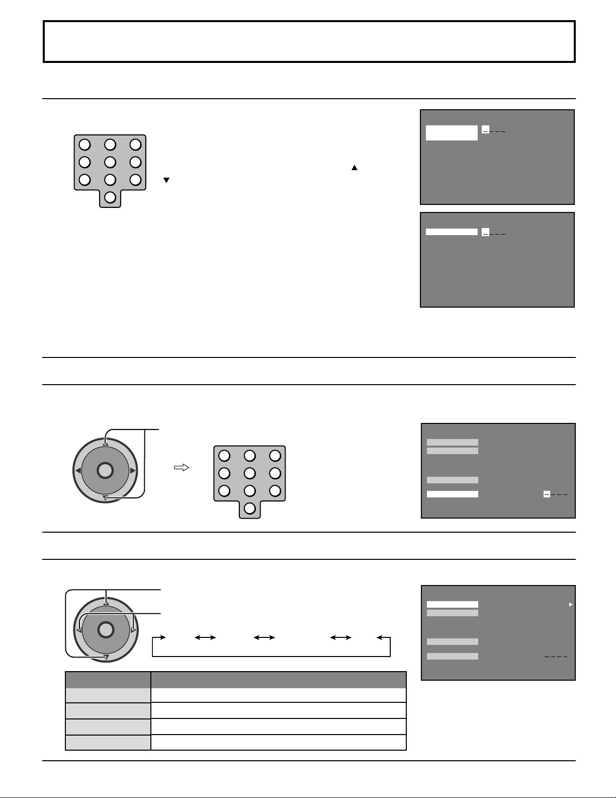
LOCK Feature
A
C
T
I
O
N
CH
CH
VOL VOL
CREATE CODE FIRST
To use LOCK options CREATE CODE FIRST.
123
456
7809
Use the remote numeric keypad to enter a four-digit
secret code.
While entering a code, by pressing the up
button you can input a new code again.
After entering your secret code for the first time, the
or down
CREATE
CODE FIRST
PRESS ACTION FOR MAIN MENU
LOCK
onscreen display will change to ENTER CODE.
LOCK
ENTER CODE
Notes:
PRESS ACTION FOR MAIN MENU
(1) Use a code that is easy to remember and record it in a safe place.
(2) If you do not remember your code, LOCK will unlock in 12, 24, or 48 hours, depending on the current setup. Be cautious
when selecting ALWAYS. If ALWAYS is selected, and you forget your secret code, the TV must be serviced by a
qualified technician to clear the LOCK setup.
CODE
If you select CODE, and you change your code from the one used in the CREATE CODE FIRST or ENTER CODE, your
new code becomes the controlling code.
Select LOCK SET to prevent video games and VCR tapes from being viewed.
LOCK SET
CH
O
I
T
N
C
A
VOL VOL
CH
MODE
OFF
GAME
CHANNEL
ALL
Press to select CODE.
123
456
7809
Use the remote numeric
keypad to enter a fourdigit secret code.
Press to select LOCK SET.
Press to select from the following.
OFF ALLCHANNELGAME
Function
Turns Lock function off.
Lock CH 3, 4 and Video inputs.
Lock up to four channels.
Locks all channels and video inputs.
LOCK
LOCK SET
V-CHIP SET
HOW LONG?
CODE
PRESS ACTION FOR MAIN MENU
LOCK SET
V-CHIP SET
HOW LONG?
CODE
PRESS ACTION FOR MAIN MENU
BLOCK PROGRAMS :
U.S. MOVIES
CHANGE CODE
LOCK
BLOCK PROGRAMS :
U.S. MOVIES
CHANGE CODE
OFF
SETTING:
12HOURS
OFF
SETTING:
12HOURS
41
Page 42
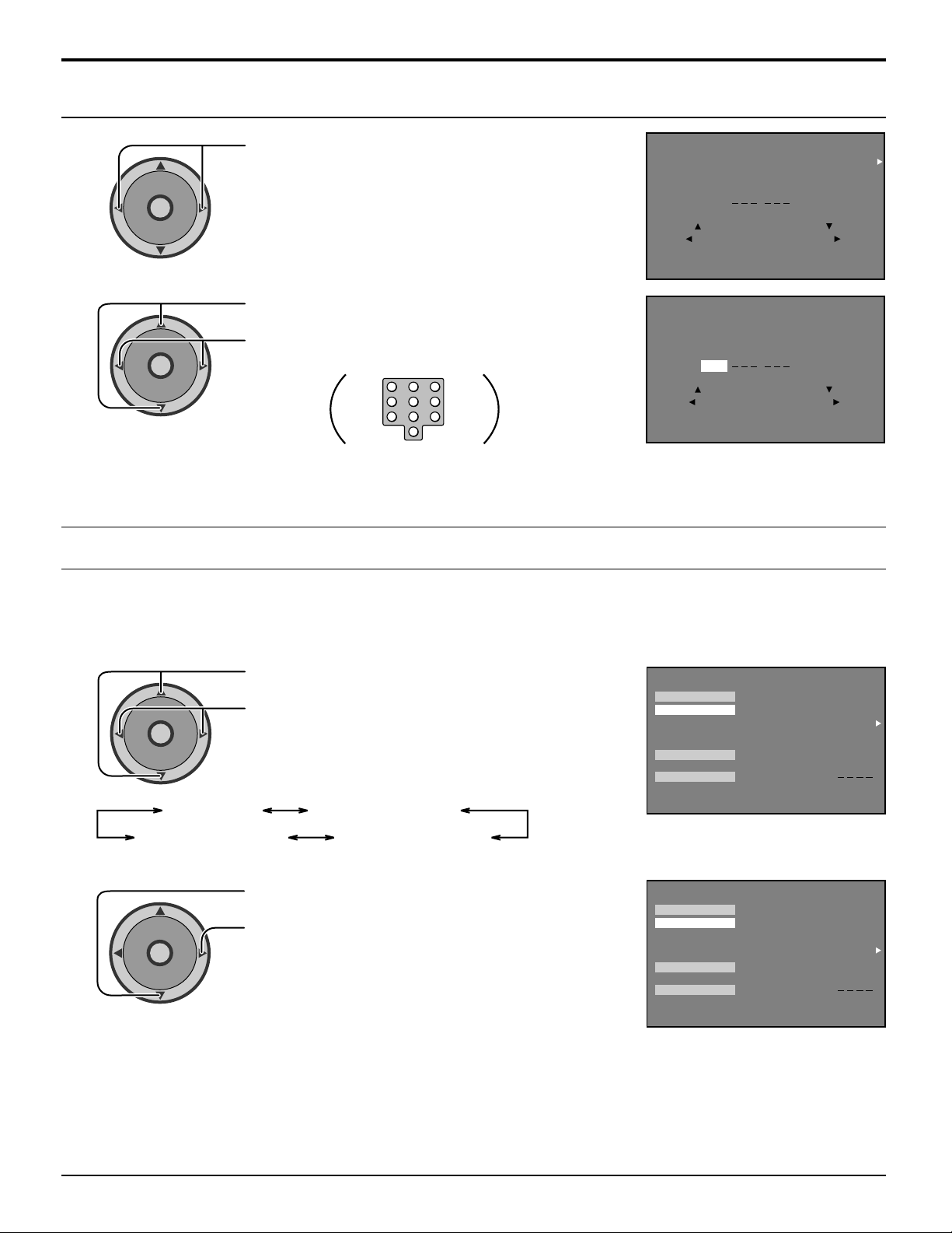
LOCK Feature
CHANNEL
Press to select CHANNEL.
1
CH
O
I
T
N
C
A
VOL VOL
CH
Press to select channel position.
2
CH
O
I
T
N
C
A
VOL VOL
CH
Repeat step 2 for up to four channels.
3
Press to select channels.
(Or use remote numeric keypad to select channels.)
123
456
7809
LOCK MODE
LOCK THESE CHANNELS
1 124
TO MOVE CURSOR
TO SELECT LOCK MODE
PRESS ACTION TO RETURN
LOCK MODE
LOCK THESE CHANNELS
1 124
TO MOVE CURSOR
TO SELECT CHANNEL
PRESS ACTION TO RETURN
LOCK
CHANNEL
LOCK
CHANNEL
V-CHIP SET
In the United States and Canada, the V-CHIP consists of two rating systems, which are MPAA (MOTION PICTURE) and TV
PARENTAL GUIDELINES. Its function is to block programs by following the rating data in the XDS data packets sent from
broadcasting stations. The user can select which rating programs should be blocked by using the LOCK MENU options.
1
2
CH
O
I
T
N
C
A
VOL VOL
CH
U.S. MOVIES
CH
O
I
T
N
C
A
VOL VOL
CH
Press to select V-CHIP SET.
Press to select from the following.
U.S. TV PROGRAMS
CANADIAN ENGLISHCANADIAN FRENCH
Press to select SETTING.
Press to enter SETTING.
LOCK
LOCK SET
V-CHIP SET
HOW LONG?
CODE
PRESS ACTION FOR MAIN MENU
LOCK SET
V-CHIP SET
HOW LONG?
CODE
PRESS ACTION FOR MAIN MENU
BLOCK PROGRAMS :
U.S. MOVIES
CHANGE CODE
LOCK
BLOCK PROGRAMS :
U.S. MOVIES
CHANGE CODE
OFF
SETTING:
12HOURS
OFF
SETTING:
12HOURS
42
Page 43
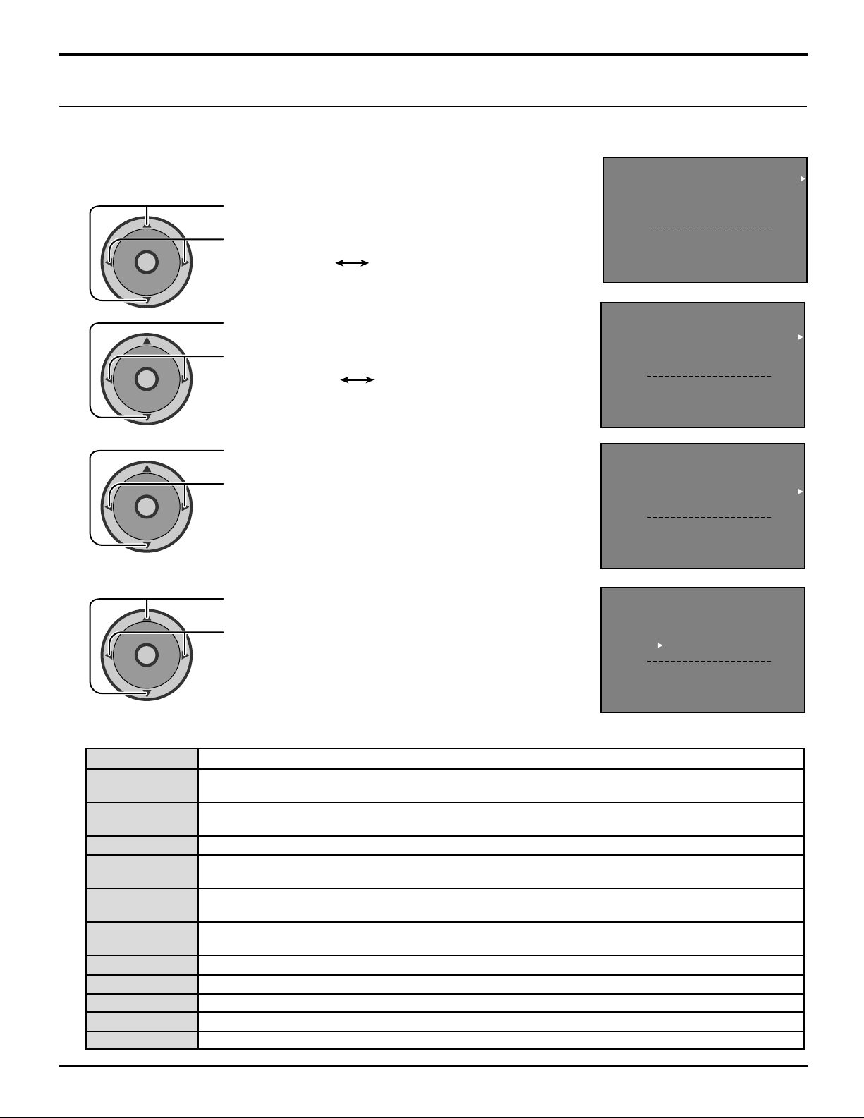
LOCK Feature
PRESS ACTION TO RETURN
U. S TV PROGRAMS
VIEW NR PROGRAMS?
SETTING:
LOCK
ON
YES
BASIC
TY-Y
TY-Y7 FV
TY-G
TY-PG V S L D
TY-1 4 V S L D
TY-MA V S L
U.S. TV PROGRAMS
This TV model features the “V-Chip technology” which allows you to use U.S. TV PROGRAMS Guide ratings to block
various types of TV programs. PIP will also be blocked automatically.
U.S. TV PROGRAMS RATING CHART
1
2
3
4
CH
O
I
T
N
C
A
VOL VOL
CH
CH
O
I
T
N
C
A
VOL VOL
CH
CH
O
I
T
N
C
A
VOL VOL
CH
CH
O
I
T
N
C
A
VOL VOL
CH
Press to select U.S. TV PROGRAMS.
Press to select U.S. TV PROGRAMS ON or OFF.
ON OFF
Press to select VIEW NR PROGRAMS?.
Press to select VIEW NR PROGRAMS? YES or NO.
NOYES
YES: NR programs will be received.
NO: NR programs will be blocked.
Press to select SETTING.
Press to select BASIC or DETAILED.
BASIC: Allows you to select only general ratings
such as TV-Y, TV-PG, etc.
DETAILED: Allows you to select both general ratings
and content such as V, L, etc.
Note: See Customer Caution.
Press to move between different ratings.
Press to select ratings you would like to block (RED)
and unblock (GREEN).
Perform Step 4 for each rating.
Note: See the U.S. TV PROGRAMS RATINGS CHART.
U. S TV PROGRAMS
VIEW NR PROGRAMS?
SETTING:
TY-Y
TY-Y7 FV
TY-G
TY-PG V S L D
TY-1 4 V S L D
TY-MA V S L
PRESS ACTION TO RETURN
U. S TV PROGRAMS
VIEW NR PROGRAMS?
SETTING:
TY-Y
TY-Y7 FV
TY-G
TY-PG V S L D
TY-1 4 V S L D
TY-MA V S L
PRESS ACTION TO RETURN
U. S TV PROGRAMS
VIEW NR PROGRAMS?
SETTING:
TY-Y
TY-Y7 FV
TY-G
TY-PG V S L D
TY-1 4 V S L D
TY-MA V S L
PRESS ACTION TO RETURN
LOCK
LOCK
LOCK
ON
YES
BASIC
ON
YES
BASIC
ON
YES
BASIC
U.S. TV PROGRAMS RATINGS CHART
NR
TV-Y
TV-Y7
TV-G
TV-PG
TV-14
TV-MA
FV
V
S
L
D
Not Rated. SEE CUSTOMER CAUTION on the next page.
All children. The themes and elements in this program are specifically designed for a very
young audience, including children from ages 2-6.
Directed to older children. Themes and elements in this program may include mild physical or
comedic violence, or may frighten children under the age of 7.
General audience. It contains little or no violence, no strong language, and little or no sexual dialogue or situations.
Parental guidance suggested. The program may contain infrequent coarse language, limited
violence, some suggestive sexual dialogue and situations.
Parents strongly cautioned. This program may contain sophisticated themes, sexual content,
strong language and more intense violence.
Mature audiences only. This program may contain mature themes, profane language, graphic
violence, and explicit sexual content.
FANTASY/CARTOON VIOLENCE
VIOLENCE
SEX
OFFENSIVE LANGUAGE
DIALOGUE WITH SEXUAL CONTENT
43
Page 44
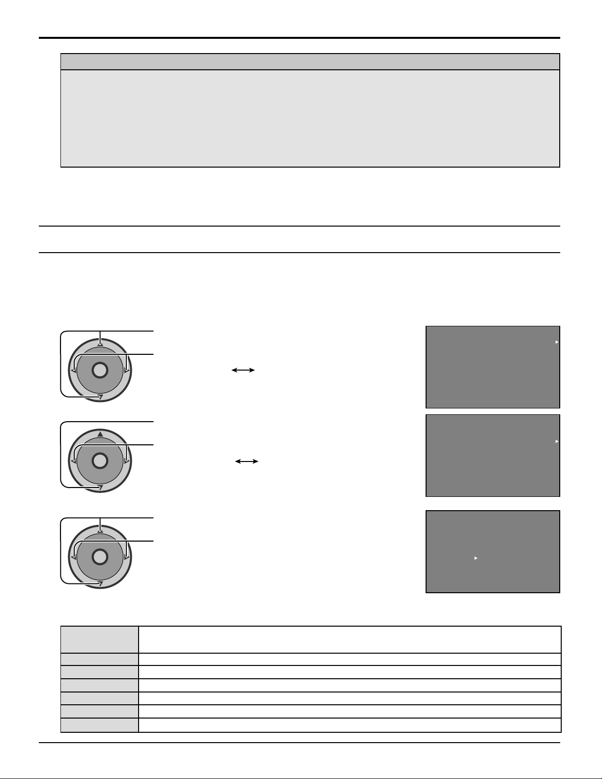
LOCK Feature
Customer Caution
The V-Chip system that is used in this set is capable of blocking “NR” programs (non rated, not applicable and
none) per FCC Rules Section15.120(e)(2). If the option of blocking “NR” programs is chosen “unexpected and
possibly confusing results may occur, and you may not receive emergency bulletins or any of the following types of
programming:”
• Emergency Bulletins (Such as EAS messages, weather warnings and others)
• Locally originated programming • News • Political • Public Service Announcements • Religious • Sports
• Weather
U.S. MOVIES
This TV model features the “V-Chip technology” which allows you to use Motion Picture Ratings when viewing movies or
video tapes. This innovation allows parents to block various types of movies and video tapes at their discretion. PIP will
also be blocked automatically.
U.S. MOVIES RATING CHART
1
CH
O
I
T
N
C
A
VOL VOL
CH
2
CH
O
I
T
N
C
A
VOL VOL
CH
3
CH
O
I
T
N
C
A
VOL VOL
CH
U.S. MOVIES RATINGS CHART
Press to select U.S. MOVIES.
Press to select U.S. MOVIES ON or OFF.
ON OFF
Press to select VIEW NR MOVIES?.
Press to select VIEW NR PROGRAMS? YES or NO.
NOYES
Note:
Some movies are not rated for a variety of reasons.
Old movies and foreign films are usually not rated.
Press to move between different ratings.
Press to select ratings you would like to block (RED)
and unblock (GREEN).
Continue Step 3 for each ratings.
Note: See the U.S. MOVIES RATINGS CHART.
U. S MOVIES
VIEW NR PROGRAMS?
G
PG
PG-13
R
NC-17
X
PRESS ACTION TO RETURN
U. S MOVIES
VIEW NR PROGRAMS?
G
PG
PG-13
R
NC-17
X
PRESS ACTION TO RETURN
U. S MOVIES
VIEW NR PROGRAMS?
G
PG
PG-13
R
NC-17
X
PRESS ACTION TO RETURN
LOCK
LOCK
LOCK
OFF
YES
OFF
YES
OFF
YES
PG-13, R, NC-17 and X will be blocked.
44
NR
CONTAINS NO RATING (NOT RATED) AND NA (NOT APPLICABLE) PROGRAMS. Movie
has not been rated or rating does not apply.
G GENERAL AUDIENCES. All ages admitted.
PG PARENTAL GUIDANCE SUGGESTED. Some material may not be suitable for children.
PG-13 PARENTS STRONGLY CAUTIONED. Some material may be inappropriate for children under 13.
R RESTRICTED. Under 17 requires accompanying parent or adult guardian.
NC-17 NO ONE 17 AND UNDER ADMITTED.
X ADULTS ONLY.
Page 45
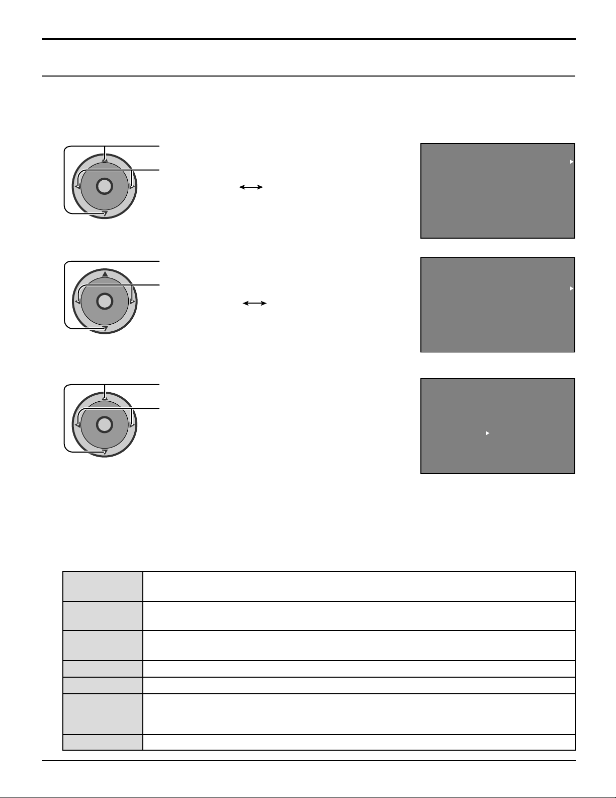
LOCK Feature
Canadian English
The V-CHIP used in this TV model allows you to block various types of movies and television programs based on the two
rating systems used in Canada. PIP will also be blocked automatically.
1
2
3
CH
O
I
T
N
C
A
VOL VOL
CH
CH
O
I
T
N
C
A
VOL VOL
CH
CH
O
I
T
N
C
A
VOL VOL
CH
Press to select CANADIAN ENGLISH.
Press to select CANADIAN ENGLISH ON or OFF.
ON OFF
Press to select VIEW E PROGRAMS?
Press to select VIEW E PROGRAMS? YES or NO.
NOYES
Note:
E (Exempt) programming includes: news, sports,
documentaries and other information programming, talk
shows, music videos, and variety programming.
Press to move between different ratings.
Press to select ratings you would like to block (RED)
and unblock (GREEN).
Note: See the CANADIAN ENGLISH RATING CHART.
LOCK
CANADIAN ENGLISH
VIEW E PROGRAMS?
PRESS ACTION TO RETURN
CANADIAN ENGLISH
VIEW E PROGRAMS?
PRESS ACTION TO RETURN
CANADIAN ENGLISH
VIEW E PROGRAMS?
PRESS ACTION TO RETURN
C
C8+
G
PG
14+
18+
C
C8+
G
PG
14+
18+
C
C8+
G
PG
14+
18+
LOCK
LOCK
OFF
YES
OFF
YES
OFF
YES
CANADIAN ENGLISH RATINGS CHART
E
C
C8+
Exempt - Exempt programming includes: news, sports, documentaries and other information
programming, talk shows, music videos, and variety programming.
Programming intended for children under age 8. No offensive language, nudity or sexual
content.
Programming generally considered acceptable for children 8 years and over. No profanity,
nudity or sexual content.
G General programming, suitable for all audiences.
PG Parental Guidance suggested. Some material may not be suitable for children.
Programming contains themes or content which may not be suitable for viewers under the age
14+
of 14. Parents are strongly cautioned to exercise discretion in permitting viewing by pre-teens
and early teens.
18+ ADULTS ONLY
45
Page 46
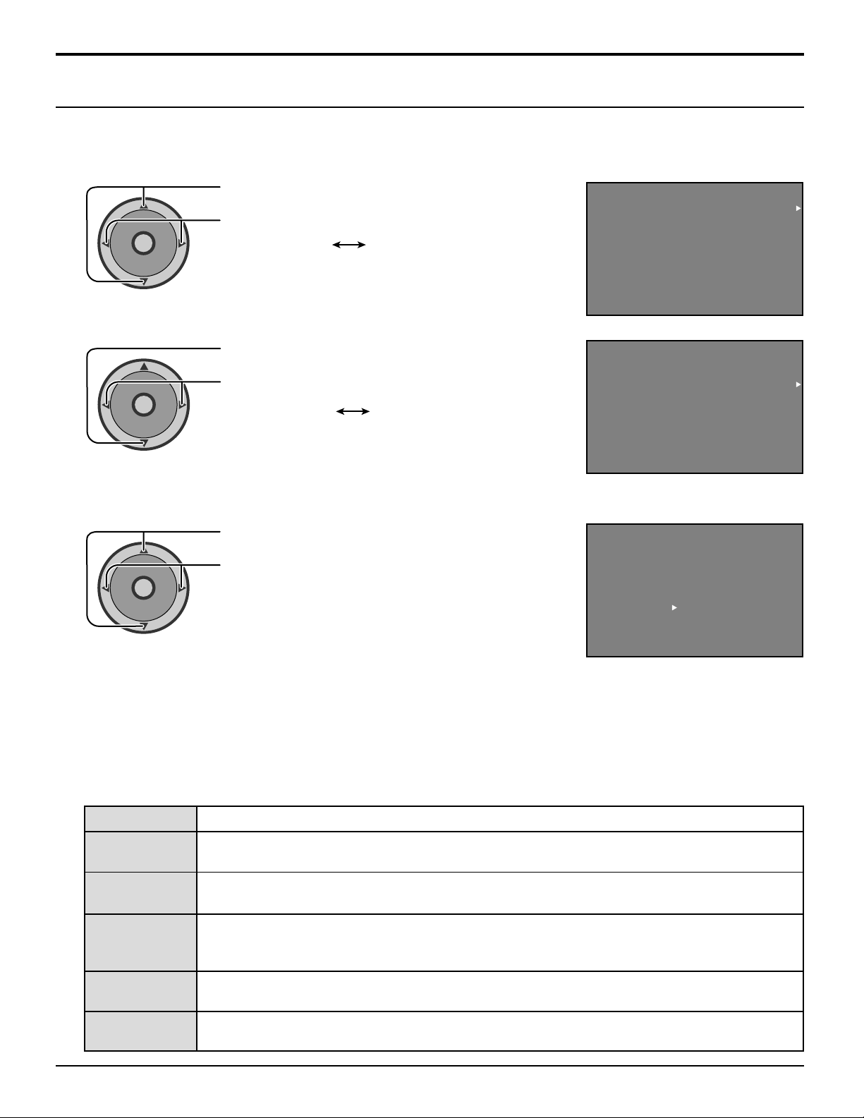
LOCK Feature
Canadian French
The V-CHIP used in this TV model also lets you block or unblock Canadian French programs according to various ratings
categories. PIP will also be blocked automatically.
1
2
3
CH
O
I
T
N
C
A
VOL VOL
CH
CH
O
I
T
N
C
A
VOL VOL
CH
CH
O
I
T
N
C
A
VOL VOL
CH
Press to select CANADIAN FRENCH.
Press to select CANADIAN FRENCH ON or OFF.
ON OFF
Press to select VIEW E PROGRAMS?
Press to select VIEW E PROGRAMS? YES or NO.
NOYES
Note:
E (Exempt) programming includes: news, sports,
documentaries and other information programming,
talk shows, music videos, and variety programming.
Press to move between different ratings.
Press to select ratings you would like to block (RED)
and unblock (GREEN).
Note: See the CANADIAN FRENCH RATINGS CHART.
LOCK
CANADIAN FRENCH
VIEW E PROGRAMS?
G
8 ANS+
13 ANS+
16 ANS+
18 ANS+
PRESS ACTION TO RETURN
LOCK
CANADIAN FRENCH
VIEW E PROGRAMS?
G
8 ANS+
13 ANS+
16 ANS+
18 ANS+
PRESS ACTION TO RETURN
LOCK
CANADIAN FRENCH
VIEW E PROGRAMS?
G
8 ANS+
13 ANS+
16 ANS+
18 ANS+
PRESS ACTION TO RETURN
OFF
YES
OFF
YES
OFF
YES
CANADIAN FRENCH RATINGS CHART
E Exempt - Exempt programming.
G
8 ANS+
General - Programming intended for audience of all ages. Contains no violence, or the
violence content is minimal or is depicted appropriately.
8+ General - Not recommended for young children. Programming intended for a broad
audience but contains light or occasional violence. Adult supervision recommended.
Programming may not be suitable for children under the age of 13 - Contains either a few
13ANS+
violent scenes or one or more sufficiently violent scenes to affect them. Adult supervision
strongly suggested.
16ANS+
18ANS+
Programming may not be suitable for children under the age of 16 - Contains frequent scenes
of violence or intense violence.
18 ans +Programming restricted to adults. Contains constant violence or scenes of extreme
violence.
13ANS+, 16ANS+ and 18ANS+ will
be blocked.
46
Page 47
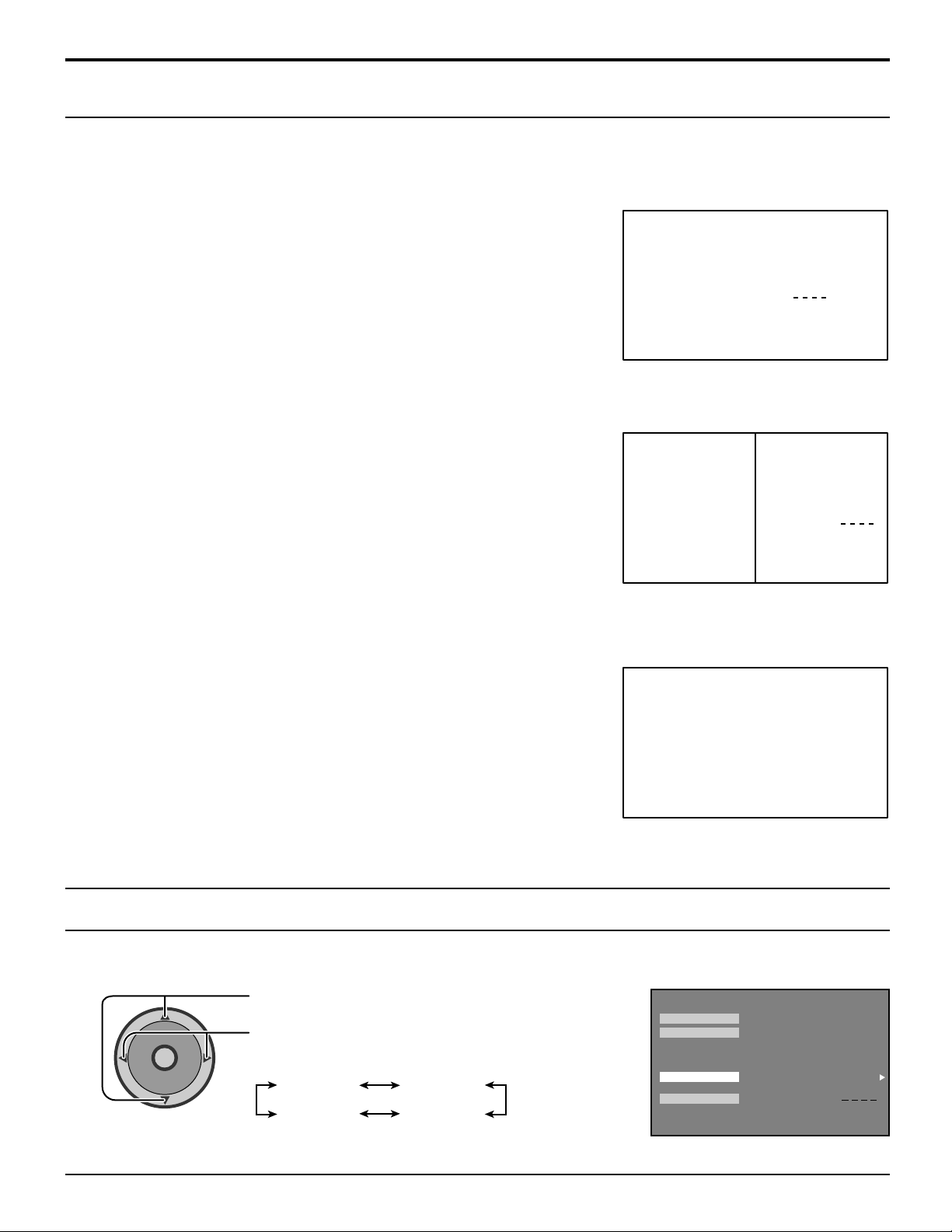
LOCK Feature
Blocking Message
If V-Chip is enabled and the program exceeds the rating limit set by you, the blocking message will appear and the audio
will be muted. Enter your four-digit secret code if you wish to continue viewing the program. After entering your code, all
locks and rating blocks are disabled until the TV is turned off or until all settings are off.
Note:
If you enter your four-digit secret code to override rating blocks, you must reset
all rating blocks by either reprogramming or turning the TV off.
Split Screen Blocking Message
Split Screen function is available when V-Chip is activated. If the program being viewed in Split Screen exceeds the set
rating limit, Split Screen will disappear and a blocking message will be displayed.
PROGRAM RATING EXCEEDED
ACCESS CODE
Note:
Enable Split Screen functions by setting Lock Set, U.S. TV PROGRAM, U.S.
MOVIES, CANADIAN ENGLISH and/or CANADIAN FRENCH to OFF.
PROGRAM
RATING
EXCEEDED
ACCESS
CODE
PIP Blocking Message
PIP function is available when V-Chip is activated. If the program being viewed in PIP exceeds the set rating limit, PIP will
disappear and a blocking message will be displayed.
Note:
Enable PIP functions by setting Lock Set, U.S. TV PROGRAM, U.S. MOVIES,
CANADIAN ENGLISH and/or CANADIAN FRENCH to OFF.
PIP RATING
EXCEEDED
HOW LONG?
After setting the LOCK SET and V-CHIP SET, set the blocking hours.
Press to select HOW LONG?
CH
O
I
T
N
C
A
VOL VOL
CH
Press to select 12HOURS/24HOURS/48HOURS /
ALWAYS.
12HOURS 24HOURS
48HOURSALWAYS
LOCK
LOCK SET
V-CHIP SET
HOW LONG?
CODE
PRESS ACTION FOR MAIN MENU
BLOCK PROGRAMS :
U.S. MOVIES
SESTTING:
CHANGE CODE
OFF
12HOURS
47
Page 48
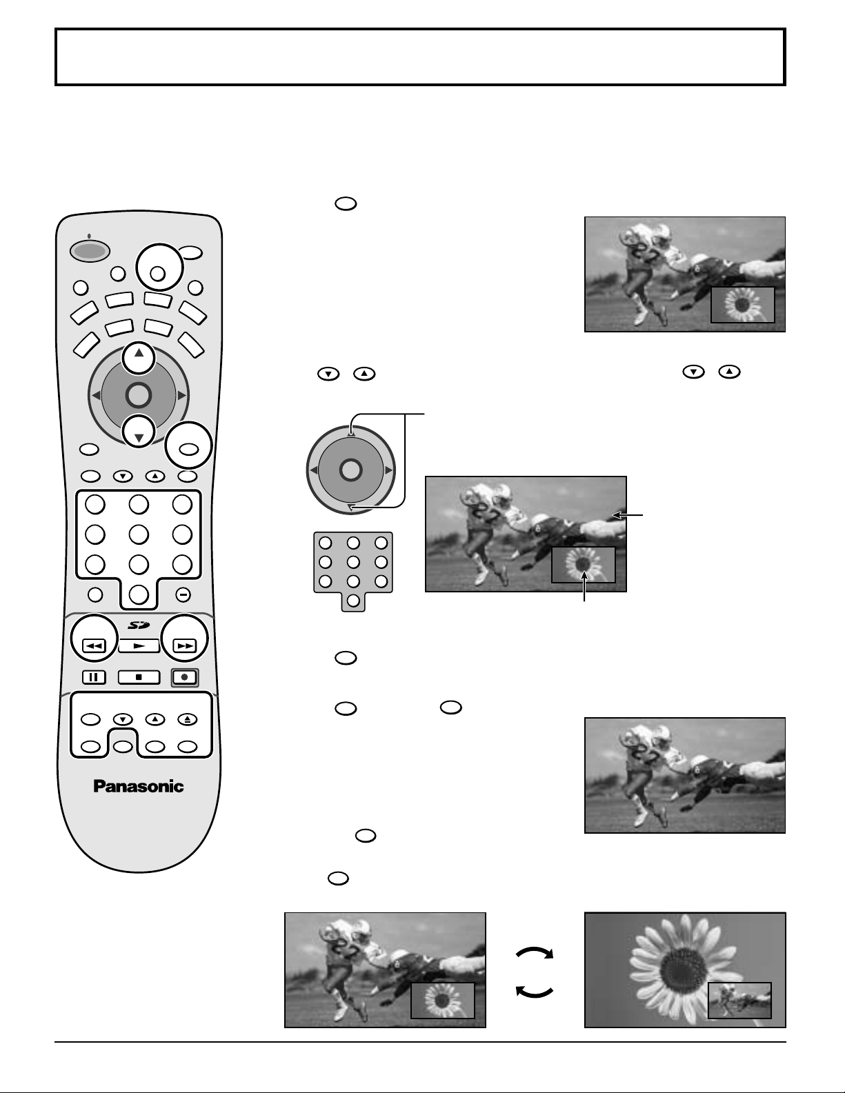
Picture in Picture Operation
This television includes a two-tuner Picture In Picture (PIP) feature. This allows you to watch two (2) live broadcasts at the
same time with or without an external video source such as a VCR, cable box, etc.
Basic PIP Operation
M
POWER
T
U
VCR
PC
MENU
A
E
TV
T
V
T
/
V
C
E
P
S
DVD
TV
D
VOL VOL
I
D
AUX
CBL
CH
O
I
T
N
C
A
CH
PAG EEXIT
123
456
789
R-TUNE PROG
0
PIP MIN
REW
PLAY
STOPPAUSE
SAP
E
O
RCVR
DBS
RECALL
GUIDE
PIP MAX
FF
REC
PIP
1
Press the PIP button on the remote control to display the PIP
Frame on screen.
Note:
L
I
G
H
T
PIP CH
2
VCR CH
3
CH
O
I
T
N
C
A
VOL VOL
CH
Audio is from Main Picture
only.
Select channels for the PIP frame by pressing
Press to select channel for the Main Picture.
or
Use the remote control numeric keypad.
PIP CH
VCR CH
.
Main Picture
123
456
7809
Picture-in-Picture Frame
4
RECALL
Press to view picture source status.
48
FREEZE
TV/VCR
SPLIT
PIP CH
VCR CH
SEARCH
OPEN/CLOSE
SWAPPIP MOVE
5
SWAP
Press
PIP
SWAP
SWAP
to switch the PIP and MAIN PICTURE source.
Press
A
PIP
again to cancel the PIP Frame.
AB
B
B
A
Page 49
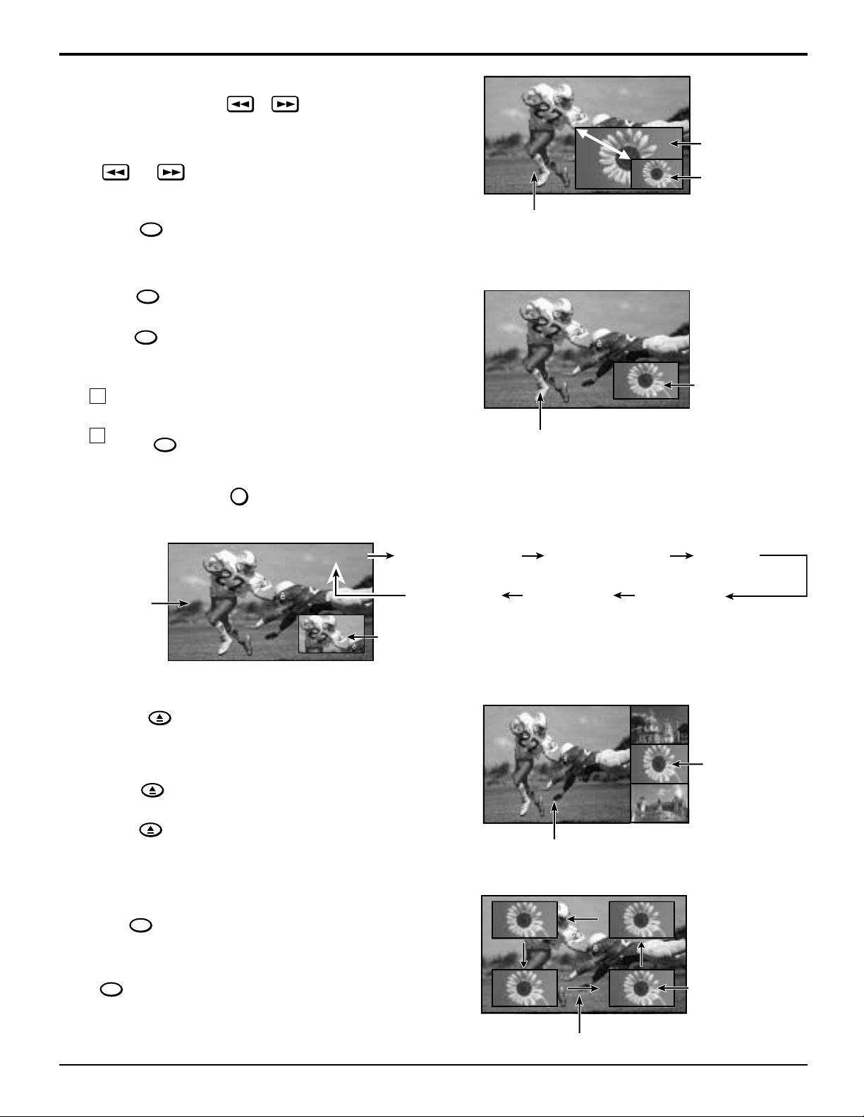
PIP MIN, PIP MAX
CH #
PIP MIN
REW
PIP MAX
FF
Picture in Picture Operation
These features are used to size PIP Frame.
PIP MIN
Press
Freeze
REW
or
FREEZE
TV/VCR
PIP MAX
FF
to size the PIP Frame.
During PIP operation this feature is used to stop action in PIP frame.
FREEZE
TV/VCR
1
2
Press
Press
to stop PIP frame action.
FREEZE
TV/VCR
again to continue action.
Note:
To stop action for Main picture:
1 In PICTURE MENU OTHER ADJ, select FREEZE
PIP or SPLIT (see page 32).
FREEZE
2 Press
TV/VIDEO Button
TV/VCR
while PIP frame is not displayed.
TV/VIDEO
Press when PIP frame is displayed to select desired input mode.
MAX
Minimum
Main Picture
FREEZE
Main Picture
CH #
PIP COMPONENT 1 PIP HDMIPIP COMPONENT 2
Main Picture
Picture-in-Picture Frame
SEARCH
Search
OPEN/CLOSE
This feature lets you scan through all available channels.
SEARCH
OPEN/CLOSE
1
2
Press
Press
SEARCH
OPEN/CLOSE
to display search frames.
again to stop search feature. This returns
the screen to the previous condition (single screen, PIP
screen or SPLIT screen).
Move
MOVE
This feature is used to move PIP frame to one of four corners.
PIP VIDEO 2PIP VIDEO 3
Main Picture
CH10
PIP VIDEO 1
CH11
CH12
Search Frames
CH13
Press
MOVE
to position PIP frame to desired corner.
PIP Frames
Main Picture
49
Page 50
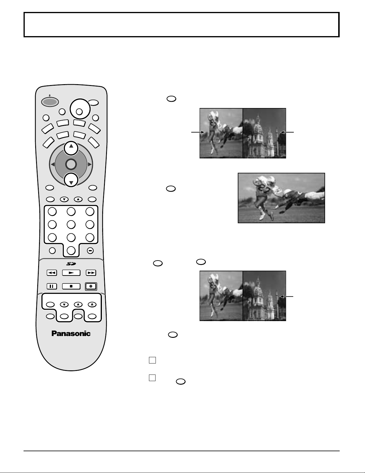
Split Screen
FREEZE
TV/VCR
This feature lets you watch two different channels side by side with or without an external video source.
The audio is from the Main picture only (left side).
Split screen enables you to search other channels on the right screen or check video recording status.
Splitting the screen
SPLIT
M
T
U
POWER
E
VCR
TV
PC
MENU
T
V
T
/
V
C
E
P
S
A
A
DVD
DTV
VOL VOL
U
CBL
CH
O
I
T
N
C
A
CH
PAG EEXIT
I
D
X
SAP
E
O
RCVR
DBS
RECALL
GUIDE
Press
1
L
I
G
H
T
Main Picture
Returning to one screen.
2
Press
to display Split screen.
(The previously selected screen appears.)
SPLIT
again to return.
Split Screen
123
456
789
R-TUNE PROG
0
PIP MIN
REW
FREEZE
TV/VCR
PIP
STOPPAUSE
PIP CH
VCR CH
PLAY
MOVE
PIP MAX
FF
REC
SEARCH
OPEN/CLOSE
SWAPSPLIT
Freezing pictures
Main Picture
During Split Screen this feature is used to stop action in SPLIT screen.
FREEZE
1
TV/VCR
Press
to stop action in SPLIT screen.
FREEZE
FREEZE
TV/VCR
2
Press
again to recover.
Note:
To stop action for Main picture:
1 In PICTURE MENU OTHER ADJ, select FREEZE
PIP or SPLIT (see page 32).
FREEZE
2 Press
TV/VCR
while SPLIT frame is not displayed.
Notes:
(1) Sound from the left screen is output from the speakers on the TV set (and headphone jack).
(2) When the screen is split, signals of the left screen are output from the rear monitor output terminal.
(3) The left and right screens are processed by individual circuits, and therefore, may have slight variation in image quality.
(4) Split screen returns to single screen when the TV is turned off.
(5) The right and left screens cannot display the same picture at the same time.
50
Page 51
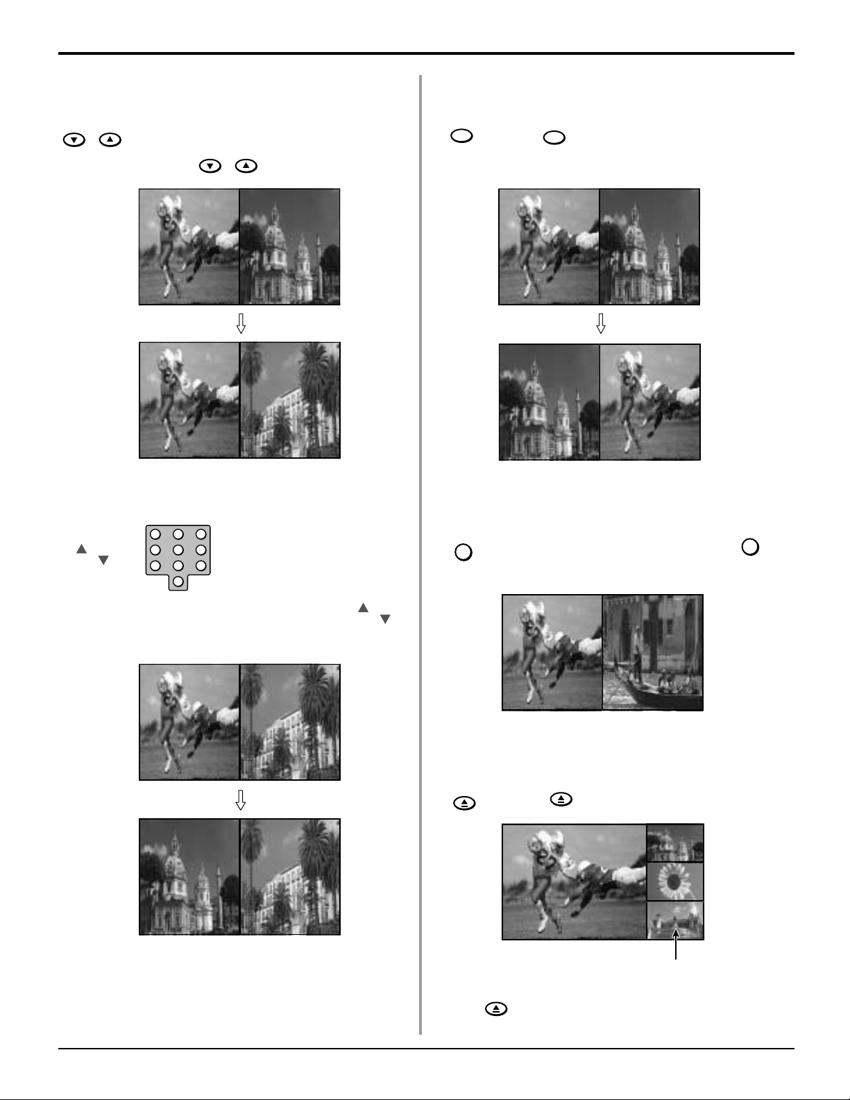
Split Screen
Changing the channels for the Split Screen Swapping left and right screens
PIP CH
VCR CH
Select channels for the Split Screen by
PIP CH
pressing
VCR CH
CH10
CH10
.
CH5
CH6
Changing the channels for the Main Picture
SWAP
Press
SWAP
MAIN PICTURE source.
Viewing Videos
to switch the SPLIT SCREEN and
CH10
CH5
CH5
CH10
123
CH
CH
456
7809
Select channels for the Main Picture by pressing
or use the remote control numeric keypad.
CH10
CH5
CH6
CH6
CH
CH
TV/VIDEO
While Split screen is displayed, press
switch modes.
CH10
VIDEO 1
Searching the other channels
SEARCH
OPEN/CLOSE
press
SEARCH
OPEN/CLOSE
to search the other channels.
CH11
CH10
CH12
CH13
TV/VIDEO
to
Search Frames
Press
again to stop the search.
SEARCH
OPEN/CLOSE
This returns the screen to its previous condition.
51
Page 52
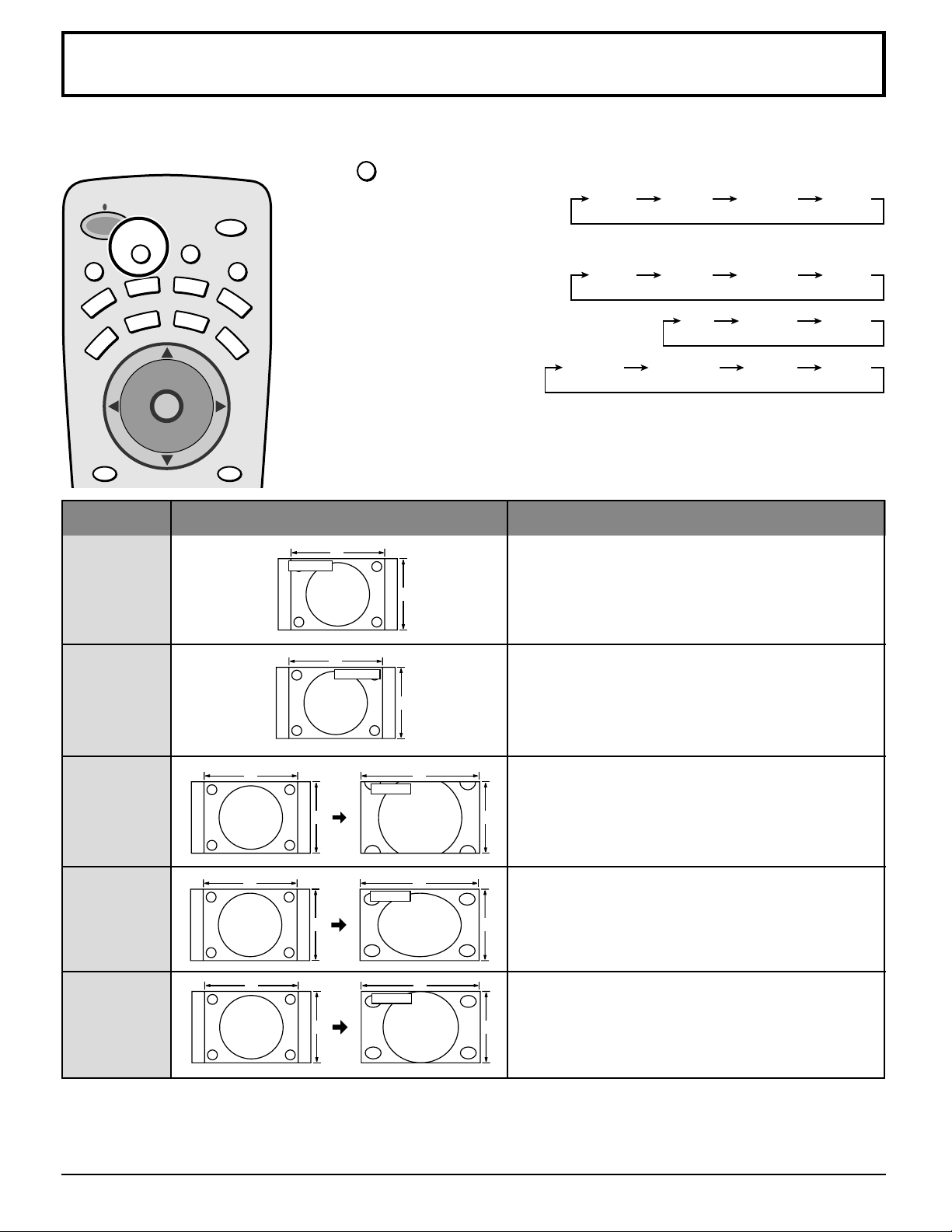
ASPECT Controls
The color monitor will allow you to enjoy viewing the picture at its maximum size, including wide screen cinema format
picture.
POWER
E
T
U
M
VCR
PC
MENU
T
C
E
P
S
A
DVD
TV
D
TV
C
A
VOL VOL
CH
T
CH
SAP
T
V
/
V
I
D
E
O
L
I
G
H
T
AUX
RCVR
CBL
DBS
O
I
N
RECALL
ASPECT
ASPECT button
The aspect mode changes each time the ASPECT button is pressed.
JUST FULLZOOM4 : 3
Note: Aspect MODE will change as follows depending on the receiving signals.
(1) 480i:
JUST FULLZOOM4 : 3
(2) 480p (including HDMI-IN):
FULLZOOM4:3
ZOOMNORMAL
FULL*(JUST)
(3) PC mode
*No signal
(4) 1080i: FULL only
(5) SPLIT SCREEN: FULL only
Mode
4 : 3
NORMAL
ZOOM
FULL
Picture Explanation
4
4 : 3
3
4
NORMAL
4 : 3 will display a 4:3 picture in its true aspect ratio.
Bars can be seen to the left and right of the image.
NORMAL will display a 4:3 picture in its true aspect
3
ratio.
Bars can be seen to the left and right of the image.
4
16
ZOOM
ZOOM mode magnifies the central section of the
3
4
16
FULL
9
picture.
FULL will display the picture at its maximum size but
3
9
with slight elongation.
JUST
4
3 9
JUST
16
JUST mode will display a 4:3 picture at its maximum
size but with aspect correction applied to the sides
of the screen so that elongation is only apparent at
the left and right edges of the screen. The size of the
picture will depend on the original signal.
Note:
The S VIDEO terminal on this set can be detected specially encoded signals that are compatible with a wide screen
monitor. When a full image from the S VIDEO terminal of specially encoded video is detected by the set, the screen size
is automatically set to FULL mode.
52
Page 53
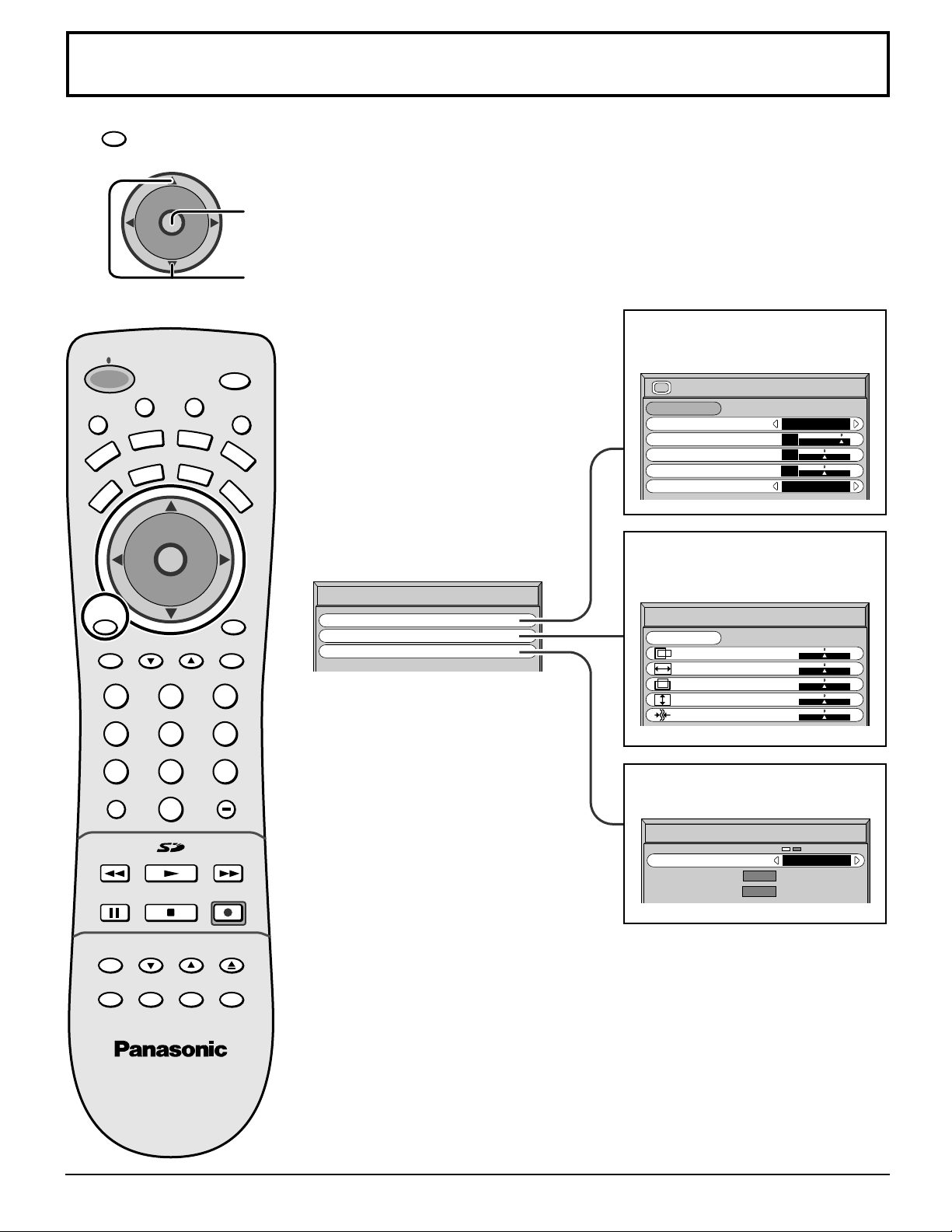
PC MENU
PC
1
MENU
Press to display the PC menu.
2
M
POWER
E
T
U
VCR
PC
MENU
TV
CH
T
C
A
VOL VOL
CH
T
C
E
P
S
A
DVD
DTV
CH
I
T
C
A
VOL VOL
CH
PAG EEXIT
123
456
O
I
N
Press to display the PC menu screen,
Press to select PICTURE/PICTURE POS./SIZE/SIGNAL
To PICTURE adjust menu
(see page 54)
SAP
T
V
/
V
I
D
E
O
L
I
G
H
T
AUX
RCVR
CBL
DBS
O
N
PICTURE
NORMALIZE
NORMAL
PICTURE MENU
PICTURE
BRIGHTNESS
SHARPNESS
COLOR TEMP
STANDARD
25
0
3
NORMAL
To PICTURE POS./SIZE
adjust menu
(see page 55)
PICTURE POS./SIZE
NORMALIZE
H-POS
H-SIZE
V-POS
V-SIZE
CLOCK PHASE
NORMAL
RECALL
GUIDE
PC MENU
PICTURE
PICTURE POS./SIZE
SIGNAL
7809
R-TUNE PROG
PIP MIN
REW
FREEZE
TV/VCR
PIP SPLIT MOVE SWAP
PLAY
STOPPAUSE
PIP CH
VCR CH
PIP MAX
REC
SEARCH
OPEN/CLOSE
To SIGNAL screen
(see page 56)
SIGNAL
FF
SYNC
H
-
FREQ. kHz
31.5
-
V
60.0
FREQ. Hz
H & V
53
Page 54
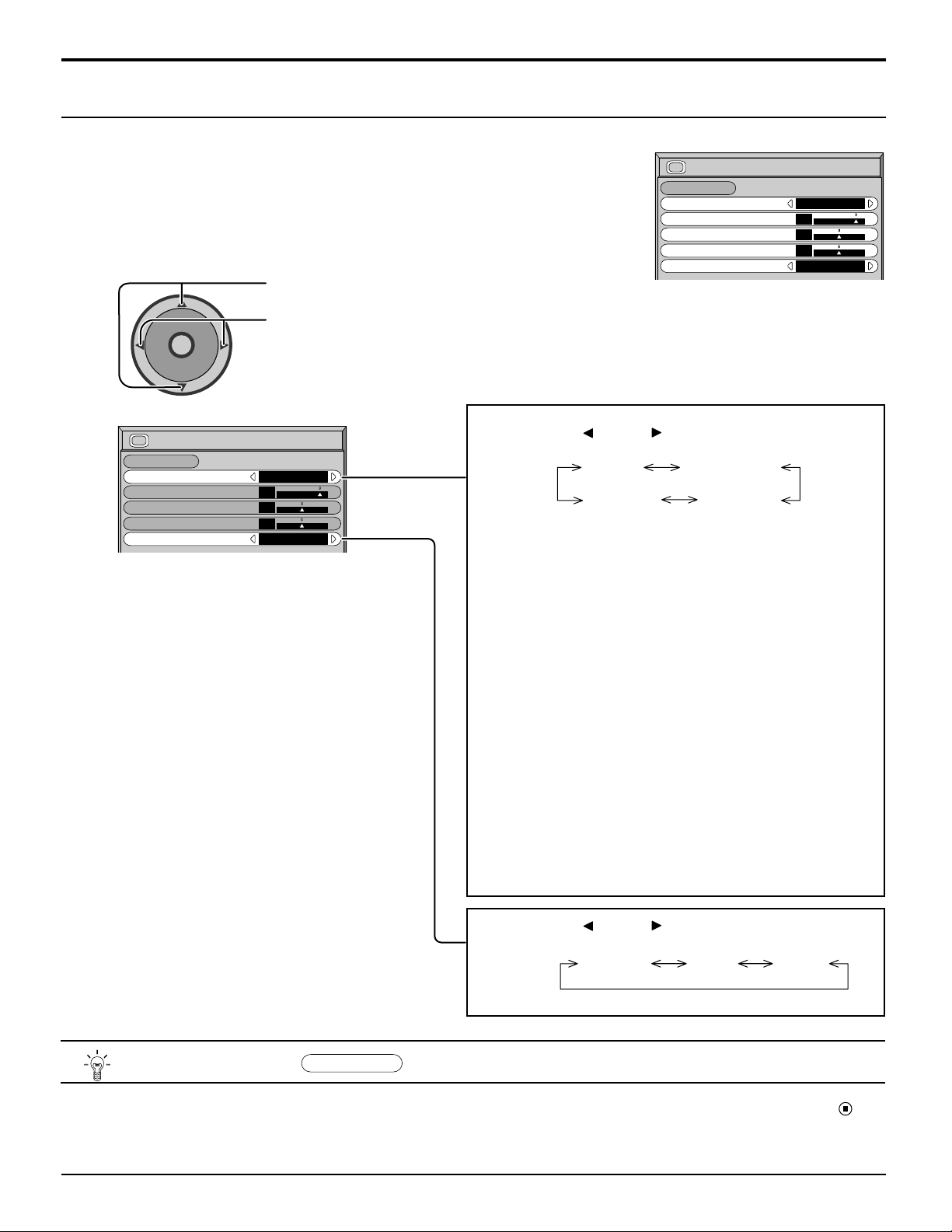
PC MENU
PICTURE Adjustments
Select PICTURE from “PC MENU” during PC input signal.
1
Select to adjust each item.
2
Press to select the menu to adjust.
CH
O
I
T
N
C
A
VOL VOL
CH
Select the desired level by looking at the picture
behind the menu.
PICTURE
NORMALIZE
PICTURE MENU
PICTURE
BRIGHTNESS
SHARPNESS
COLOR TEMP
NORMAL
STANDARD
25
0
3
NORMAL
PICTURE
NORMALIZE
PICTURE MENU
PICTURE
BRIGHTNESS
SHARPNESS
COLOR TEMP
NORMAL
STANDARD
25
0
0
NORMAL
Press the left
or right
button to switch between
modes.
AUTO STANDARD
CINEMA DYNAMIC
AUTO
Automatically selects the mode that best suits the
brightness of the environment.
STANDARD
For viewing in standard (evening lighting) environments.
This menu selects the normal levels of BRIGHTNESS
and PICTURE.
DYNAMIC
For viewing in brighter environments.
This menu selects higher than normal levels of
BRIGHTNESS and PICTURE.
CINEMA
Ideal for movies.
Note:
If you would like to change the picture and color of the
selected PICTURE menu to something else, adjust using
the items in the PICTURE menu. (see next page)
Press the left
or right
button to switch between
modes.
NORMAL COOL WARM
Helpful Hint (
NORMALIZE
Normalization)
While the “PICTURE” menu is displayed, if either the N button on the remote control is pressed at any time or the
(ACTION button) is pressed during “NORMALIZE”, then all adjustment values are returned to the factory settings.
54
Page 55
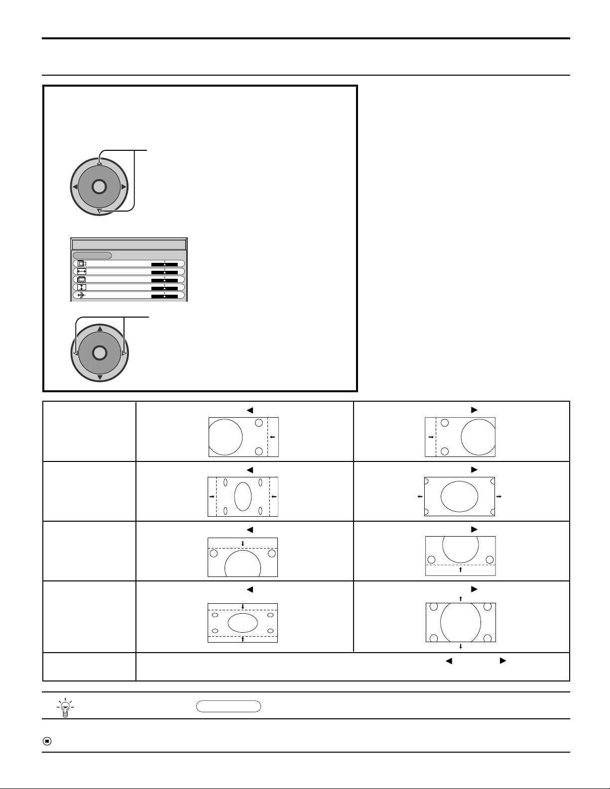
Adjusting PICTURE POSITION/SIZE
Adjusting screen
Select PICTURE POS./SIZE from the “PC MENU” during PC
1
input signal.
2
CH
O
I
T
N
C
A
VOL VOL
CH
During “RGB” input signal.
Press to select H-POS/H-SIZE/V-POS/
V-SIZE/CLOCK PHASE.
PC MENU
3
PICTURE POS./SIZE
NORMALIZE
H-POS
H-SIZE
V-POS
V-SIZE
CLOCK PHASE
CH
O
I
T
N
C
A
VOL VOL
CH
H-POS
H-SIZE
NORMAL
Press to adjust POS./SIZE.
When the Position Left
When the Position Left
When the Position Left
“ ”
button is pressed
“ ”
button is pressed
“ ”
button is pressed
Note:
If a “Cue” or “Rew” signal from a VCR or DVD
player is received, the picture position will shift
up or down. This picture position movement
cannot be controlled by the PICTURE POS./
SIZE function.
When the Position Right
When the Position Right
When the Position Right
“ ”
button is pressed
“ ”
button is pressed
“ ”
button is pressed
V-POS
When the Position Left
“ ”
button is pressed
When the Position Right
“ ”
button is pressed
V-SIZE
CLOCK PHASE
(RGB/PC in Mode)
Helpful Hint (
Flickering and distortion can be eliminated by using the Position Left
carry out adjustment.
NORMALIZE
Normalization)
“ ”
or Right
“ ”
button to
While the PICTURE POS./SIZE display is active, if either the N button on the remote control is pressed at any time or the
(ACTION button) is pressed during “NORMALIZE”, then all adjustment values are returned to the factory settings.
55
Page 56
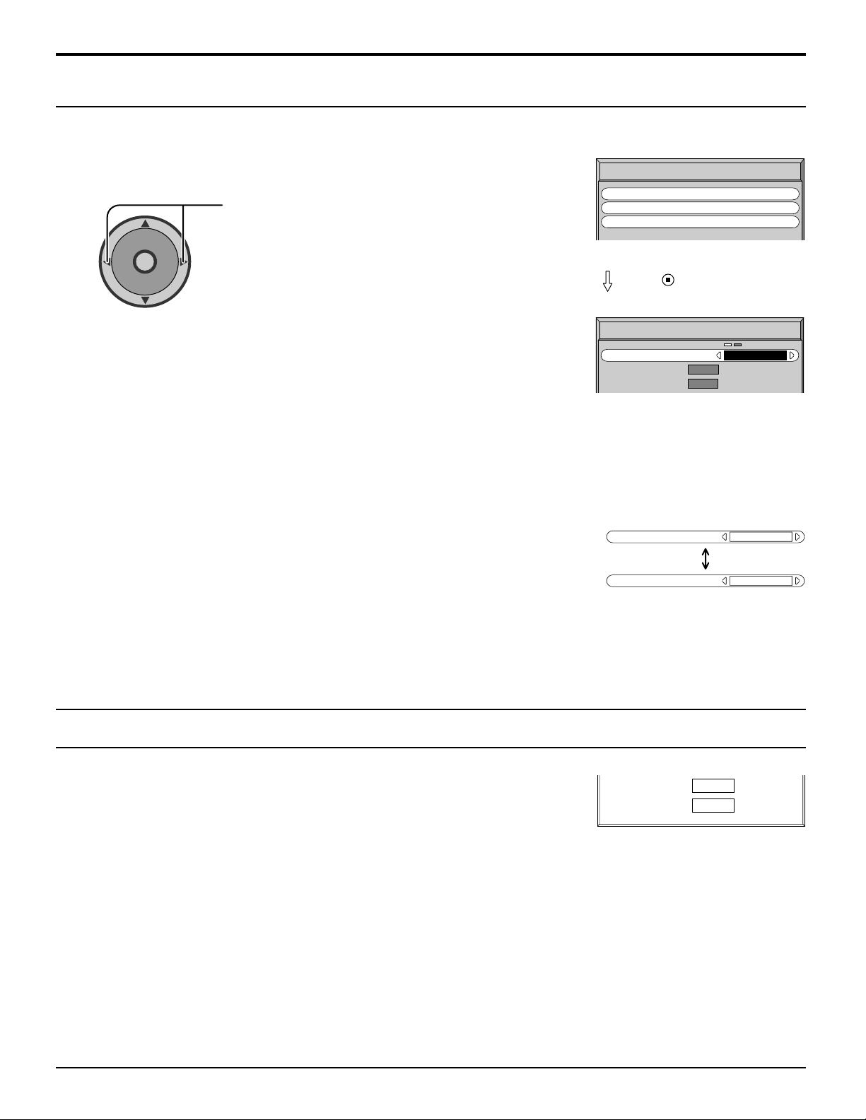
PC MENU
SYNC
Select SIGNAL from the “PC MENU” menu during PC input signal.
Press to select each item.
CH
O
I
T
N
C
A
VOL VOL
CH
Note:
Sync cannot be adjusted while a DVI signal is being applied.
Setting RGB sync signal
Confirm that the input is set to RGB INPUT (this setting is valid only for RGB INPUT
signal).
PC MENU
Press
SIGNAL
SYNC
H
V
SYNC
PICTURE
PICTURE POS./SIZE
SIGNAL
(ACTION) button
-
FREQ. kHz
31.5
-
60.0
FREQ. Hz
H & V
H & V
H & V:
The H and V sync signals are input from the HD/VD connector.
ON G: Uses a synchronized signal on the Video G signal, which is input
from the G connector.
H-FREQ. (kHz)/V-FREQ. (Hz)
Displays the H (Horizontal)/V (Vertical) frequencies.
This display is valid only for RGB input signal.
Display range:
Horizontal 15 - 110 kHz
Vertical 48 - 120 Hz
SYNC
H-FREQ. kHz
V
-
FREQ. Hz
31.5
60.0
ON G
56
Page 57
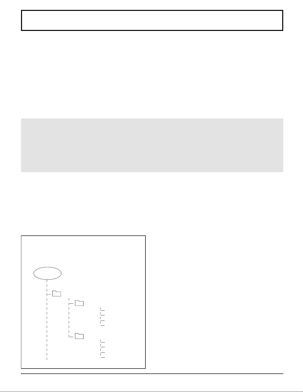
JPEG Viewer (SD Card/PC Card)
Still image data (JPEG) made with a digital camera, digital video camera, or PC can be played back using an SD
Card/PC Card.
Displayable Image Formats:
Baseline JPEG
(80 x 60 ~ 5120 x 3840 pixels)
Notes:
• Some parts of an image may not be displayed or the image may be displayed on a smaller scale depending on the
size of the image.
• Only JPEG images can be displayed on this Television.
Card Data Protection
• Do not remove the card while it is being accessed.
• Do not touch the terminals on the back of the SD Card/PC Card.
• Electrical interference, electrostatic discharges and malfunctions of the unit or card may all result in damage to the
card or data loss. It is recommended that any important data also be backed up on a PC.
• Stored data should be periodically backed up as a protection against data corruption, data loss or device malfunction.
Please note that our company shall not accept any liability for damage or loss of stored data.
Caution
• Always insert card in the correct direction. Failure to do so may result in damage to the card and this unit.
• The SD Card and PC Card are precision devices. Do not subject them to excessive pressure or strong impacts.
Folders and Files
Digital cameras that are compliant with DCF specifications use folders with a specific structure. The following diagram
shows an example of the folder structure.
DCIM Folder
Example:
If the Card file hierarchy is displayed on the PC
as shown in diagram at below.
ROOT
DCIM
100_PANA
P1000001.jpg
P1000002.jpg
P1000003.jpg
P1000004.jpg
The digital camera creates this folder automatically.
100_PANA Folder
Folder names consist of a 3-digit folder number which is
followed by five arbitrary characters. Digital camera
images are stored within these folders.
JPEG files in the 100_PANA folder are displayed when a
Card, which is structured as shown left, is inserted. To
display another folder, see page 69 INDEX AREA
OPERATION.
Note:
The folder name may vary according to the digital camera
being used.
101_PANA
P1010001.jpg
P1010002.jpg
P1010003.jpg
P1010004.jpg
P1000001.JPG: DCF File
File names consist of four arbitrary characters followed by
a 4-digit file number. DCF files are image files
(normally JPEG files) that have been taken by a digital
camera.
57
Page 58
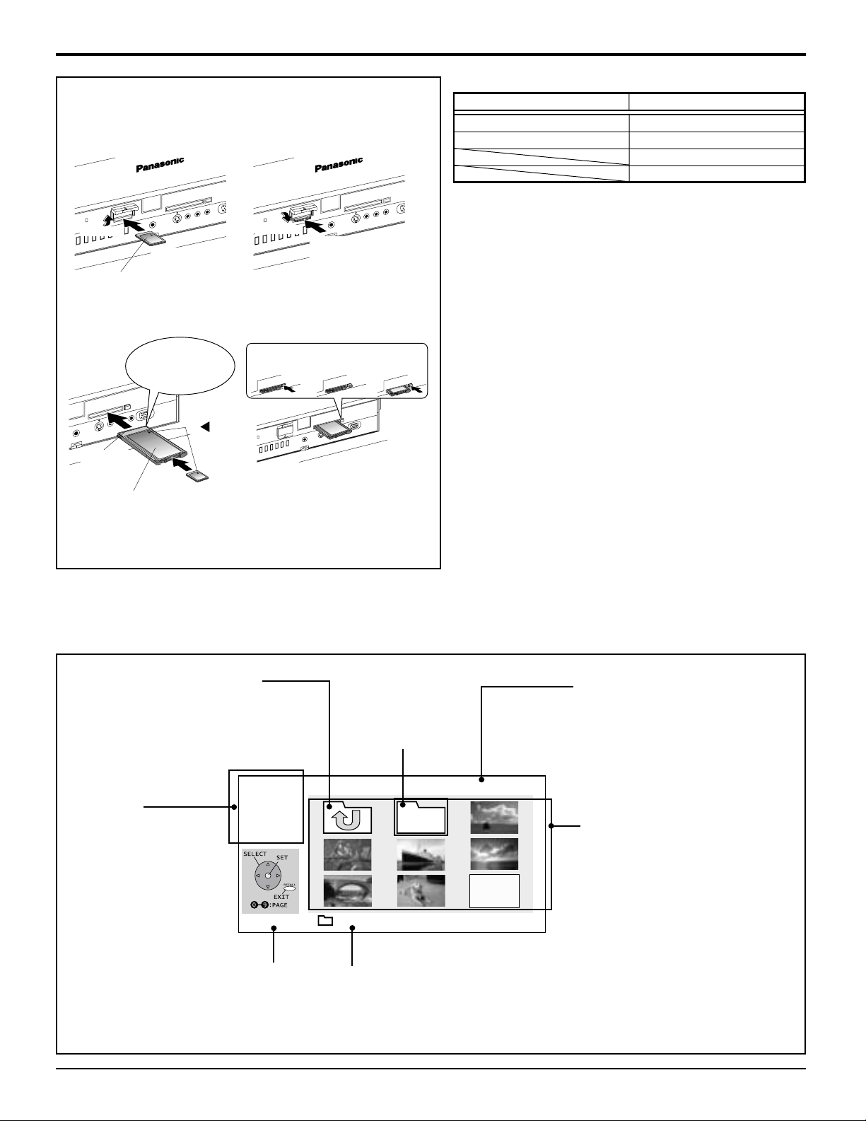
JPEG Viewer (SD Card/PC Card)
Insert the Card.
Front Card Slot
Insertion Removal
D
R
A
C
C
P
T
C
JE
E
D
R
A
C
T
D
C
S
JE
-E
H
S
U
P
1. Raise.
C
P
D
R
A
C
T
D
C
S
JE
-E
SH
U
P
2. Lower.
2. Insert it
to the depth.
Direct the
label side upward.
Remove the Card.
Insertion Removal
securely insert it to
PC CARD
EJECT
Terminal
face to
the depth
Direct the
label side upward.
Holding
both edges,
the depth.
PC
Align the
direction
of mark.
1. Push. 2. The removal
SD CARD
PUSH-EJECT
If the removal button does not pop
out and PC card can not be removed,
Push in PC card again, and proceed
with 1 to 3 for the removal button.
If PC card adapter is used, remove it
together with the adapter.
C
PC
C
E
J
E
1. Push the center
of the card.
button pops
out.
PC CARD
EJECT
3. Push.
PC
Compatible Card
SD Card slot PC Card slot
SD Card Compact Flash*
Multi Media Card Smart Media*
Memory Stick*
xD Picture Card*
D
R
A
T
C
P
• The media* listed in the right column above can be read via
the PC Card in the PC Card adaptor.
• Hard disk PC Cards, Flash ATA Cards, and other recorded
media cannot be used.
• Place the selected media onto the PC Card and then insert
into the PC Card Slot.
• When both an SD Card and PC Card are inserted, the SD
Card contents has priority and will be displayed.
• If the Card is unusable, “CARD FORMAT NOT
SUPPORTED” is displayed on-screen. Remove the Card
only when ACCESS is not displayed.
• If an incompatible JPEG file is displayed (full size file
preview), “DATA FORMAT NOT SUPPORTED” is displayed.
Notes:
• Insert/remove Card while “Card Menu Screen” or “No Card”
is displayed.
• Be sure ACCESS is not displayed before Card insertion/
removal.
• Fully insert the Card (ACCESS is displayed). Wait until
ACCESS goes out before removing.
• Before reinserting a Card after removing it, wait until “NO
CARD” is displayed. If there are Cards in both Card Slots,
wait until the Card Menu Screen of the other Slot is
displayed and ACCESS is no longer displayed before
reinserting a Card.
Card Menu Screen
The screen below is displayed automatically when a card is inserted. If “NO CARD” appears, confirm that a card
is correctly inserted.
Parent Folder
Returns currently
displayed folder to
the parent (previous)
folder.
Menu Area
Select display method
(SINGLE PLAY or
SLIDE SHOW).
Confirm the displayed
card type (SD Card or
PC Card).
ACCESS Indication
ACCESS is displayed
while data is read.
-MENU- PAGE: 1/6
SINGLE
SLIDE
SD/PC
TI
C
O
A
N
ACCESS 200_PANA
Subfolder
The subfolder of
the currently
displayed folder is
opened.
JPEG
Folder Name Area
The name of the selected
subfolder (framed in
yellow) is displayed.
Display Page No.
When the displayed files/
folders fill more than one page,
the total number of pages is
displayed.
Index Area
Folders and files are
displayed here.
Notes:
• Up to 1 000 JPEG files can be
displayed. (This number may
be lower if subfolders, or files
other than JPEG are included
in the folder.)
• Depending on JPEG file type,
“JPEG” will be displayed
instead of thumbnail image.
Note:
Only JPEG files can be displayed.
58
Page 59
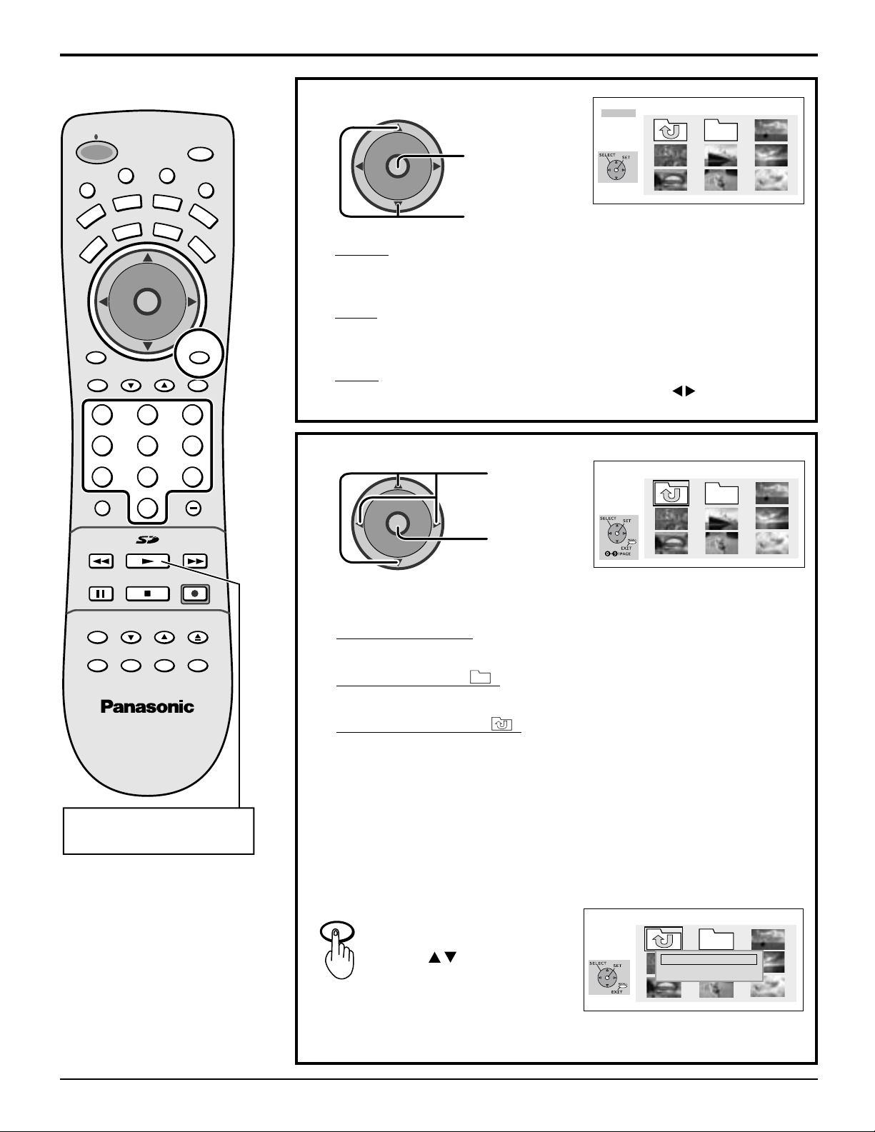
JPEG Viewer (SD Card/PC Card)
U
M
POWER
E
T
VCR
TV
PC
MENU
A
T
V
T
/
V
C
E
P
S
DVD
TV
D
VOL VOL
I
A
U
X
CBL
CH
O
I
T
N
C
A
CH
PAG EEXIT
D
123
456
789
R-TUNE PROG
0
PIP MIN
REW
PLAY
SAP
E
O
RCVR
DBS
RECALL
GUIDE
PIP MAX
FF
MENU Area Operation
CH
O
I
T
N
C
A
L
I
G
H
T
VOL VOL
CH
Press to move
to index area.
-MENU- PAGE: 1/6
SINGLE
SLIDE
SD/PC
I
T
C
O
A
N
Press to select MENU.
SINGLE
A single image selected from the index area fills the screen.
You can also rotate the image and view image information. (PP. 60-61)
SLIDE
Images are displayed one after another as a slide show. Also, the SPEED
and Transition features (p. 61) can be used.
SD/PC
When both an SD Card and PC Card are inserted, the buttons can be
used to select a card in the index area.
Index Area Operation
-MENU- PAGE: 1/6
SINGLE
SLIDE
SD/PC
TI
C
O
A
N
CH
O
I
T
N
C
A
VOL VOL
CH
Press to select
icon.
Press to set
REC
SEARCH
OPEN/CLOSE
SWAPPIP MOVE
FREEZE
TV/VCR
SPLIT
STOPPAUSE
PIP CH
VCR CH
Press to display again the
still pictures in SD/PC Card.
To select a page directly, enter the page number with the Number Keys,
then press ACTION.
Select an Image file.
Display full size file preview.
Select a Subfolder ( ).
Display files/folders contained in the folder.
Select a Parent folder ( ).
Make changes to the parent (previous) directory display.
Notes:
File and folder names will not be displayed correctly if...
• More than 8 characters are used.
• Spaces and special symbols are used. Use care when changing file
and/or folder names.
RETURN Operation
RECALL
Press RECALL to display
RETURN MENU.
Press to select an
item, and press ACTION.
RETURN:
Returns to the parent (previous) folder.
RETURN TO MENU:
Returns to Menu Area screen.
-MENU- PAGE: 1/6
SINGLE
SLIDE
SD/PC
TI
C
A
O
N
RETURN
RETURN TO MENU
59
Page 60
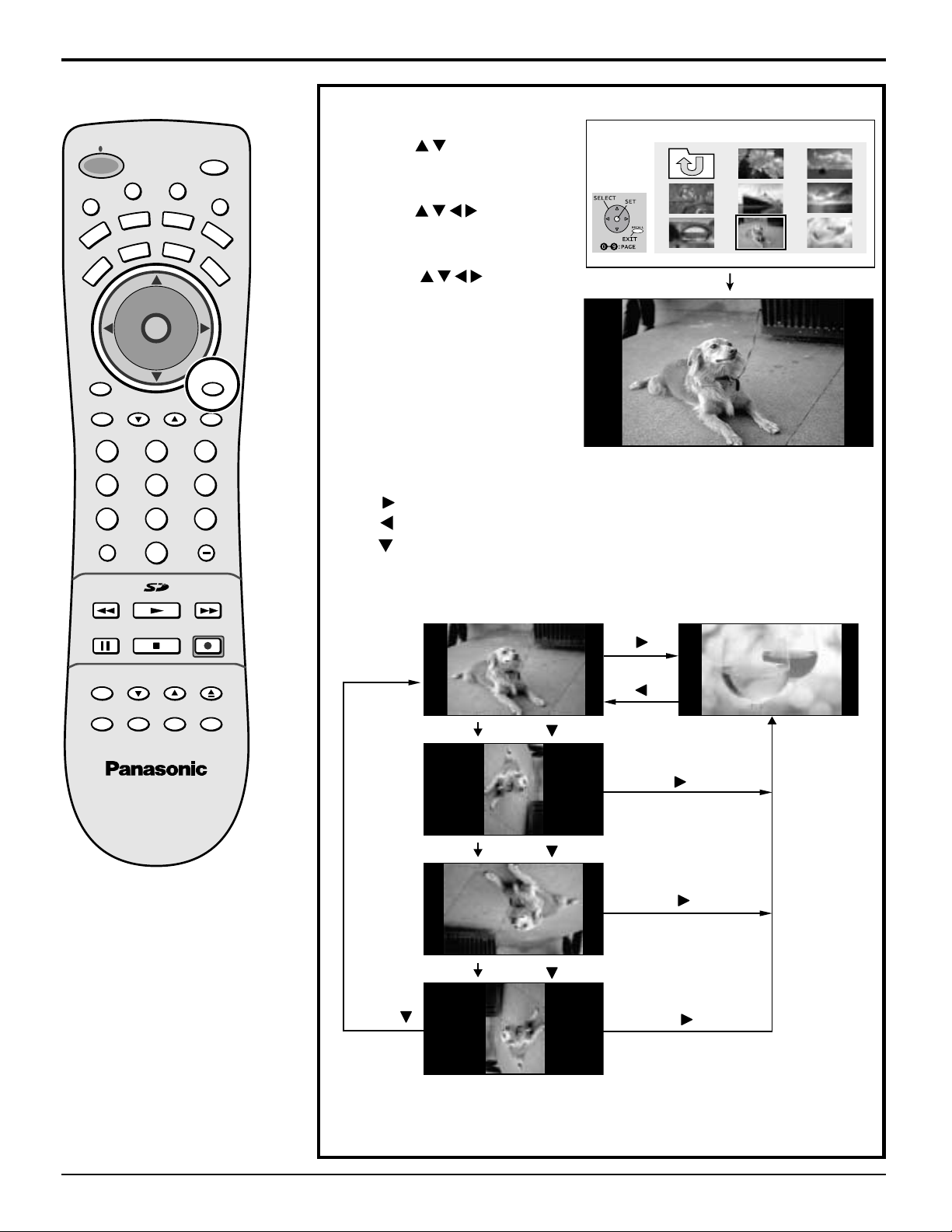
JPEG Viewer (SD Card/PC Card)
Single Play Mode
Press to select
1
“SINGLE,” and press
ACTION.
Press to move
cursor to desired file in
INDEX AREA.
(Press to display
next/previous page of 9
thumbnail files),
Press ACTION to display
file in full screen size.
M
POWER
T
U
VCR
PC
MENU
E
TV
T
V
T
/
V
C
E
P
S
A
A
U
DVD
CBL
DTV
CH
O
I
T
N
C
A
VOL VOL
CH
I
D
X
SAP
E
O
RCVR
DBS
RECALL
L
I
G
H
T
-MENU- PAGE: 1/6
SINGLE
SLIDE
SD/PC
I
T
O
C
N
A
PAG EEXIT
GUIDE
123
456
789
R-TUNE PROG
0
PIP MIN
REW
FREEZE
TV/VCR
SPLIT
PLAY
STOPPAUSE
PIP CH
VCR CH
PIP MAX
FF
REC
SEARCH
OPEN/CLOSE
SWAPPIP MOVE
SINGLE VIEW SCREEN
Press : The next image is displayed.
Press : The previous image is displayed.
Press : Each press rotates image 90˚.
Press
Press
Press
Press
Press
60
Press
Press
Press
Press
Continued in left column of next page.
Page 61
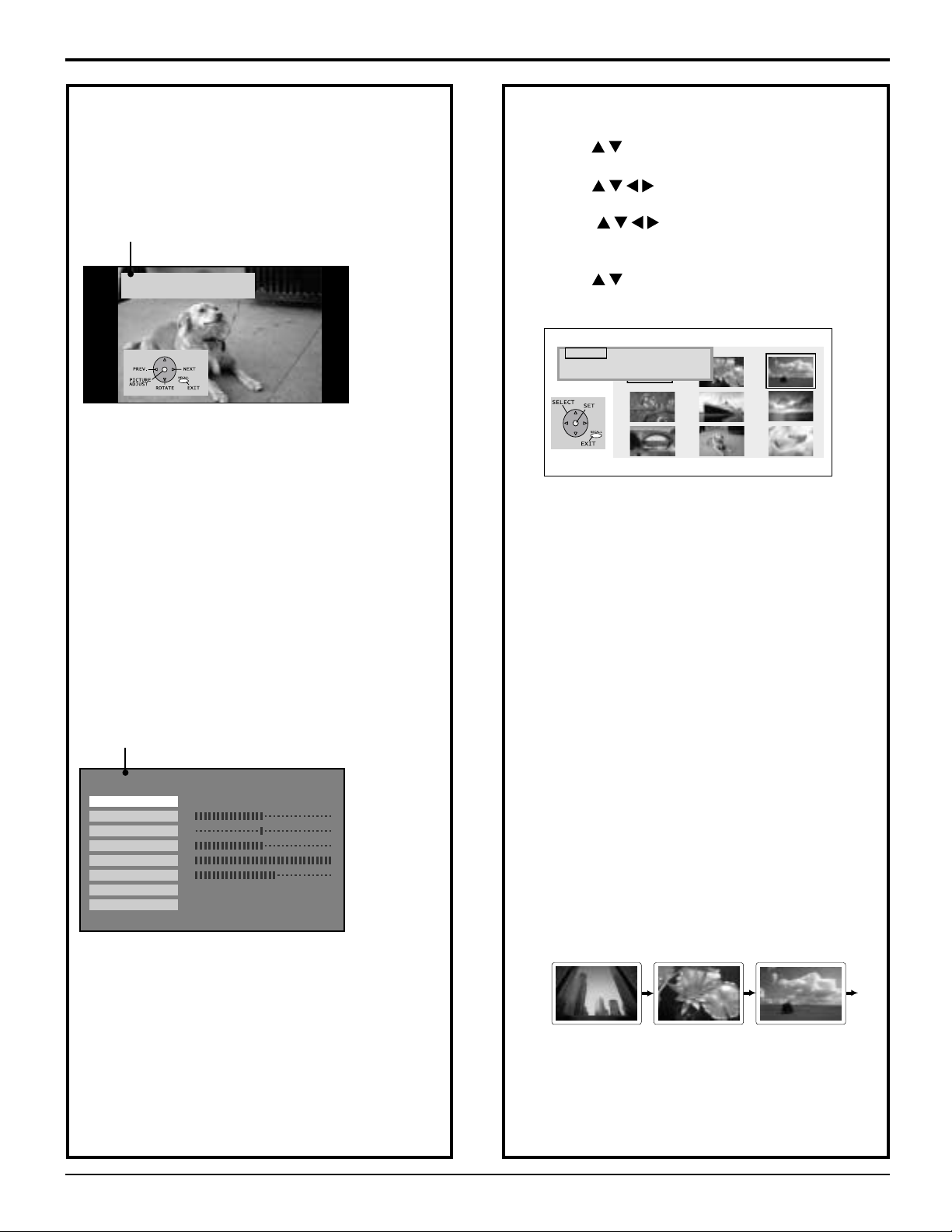
JPEG Viewer (SD Card/PC Card)
...
Continued from page 60.
Information Screen Display
Press ACTION: INFORMATION SCREEN is displayed.
(Rotation angle is maintained.)
Information Screen
FILE P2000006
DATE 07/31/2003
CTIO
N
A
Pressing RECALL returns to SINGLE VIEW
SCREEN.
Note:
• If a file name exceeds 8 characters, a file name
different from the original is displayed.
Picture Adjustment
When ACTION is pressed while the Information
Screen is displayed, the Picture Adjust menu
(Page 30 and 31) is displayed. (Rotation angle is
maintained.)
Picture Adjust menu
PICTURE
PIC MODE
COLOR
TINT
BRIGHTNESS
PICTURE
SHARPNESS
NORMAL
COLOR TEMP
PRESS RECALL TO EXIT
Pressing RECALL returns to SINGLE VIEW
SCREEN.
VIVID
SET
NORMAL
Slide Show Mode
Press to select “SLIDE,” and press
1
ACTION.
Press to move cursor to desired file in
Index Area.
(Press to display next/previous page of
9 thumbnail files),
Press ACTION to display SLIDE MENU.
Press to select an item, and press
ACTION repeatedly to set.
-MENU- PAGE: 1/6
START
SINGLE
SPEED
SLIDE
TRANSITION:NORMAL
SD/PC
T
I
C
O
A
N
[START]
Starts slide show.
[SPEED]
FAST:
Image transition every
2 seconds.
MEDIUM:
Image transition every
5 seconds.
SLOW:
Image transition every
10 seconds.
[Transition]
NORMAL:
Image transition one by one.
WIPE:
Image transition from top to bottom.
SPLIT:
Image transition from center to edge.
BLIND:
Image transition in a series of band-like shapes
that resemble window blinds.
START SLIDE SHOW.
2
:FAST
Note:
The display intervals of
2, 5, and 10 seconds do
not include file data
reading time. The display
interval becomes longer
depending on the JPEG
size.
Press RECALL with SINGLE VIEW screen
2
displayed to return to the Index Area menu.
Press ACTION to stop or resume slide show.
Press RECALL to exit this mode.
3
61
Page 62
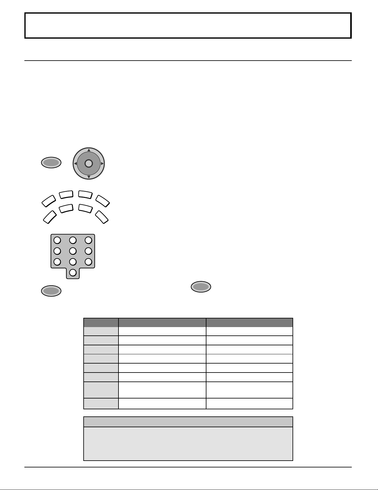
Operating peripheral equipment using the remote control
TV
DTV
CBL
AUX
DVD
VCR
DBS
RCVR
Programming The Illuminated Remote Control Using Access Codes
The Universal Remote Control can be programmed to operate many manufacturers’ components, using the component
function buttons for VCR, DVD, AUX, RCVR, TV, DTV CABLE or DBS. Follow the procedures for programming your
Remote Control with or without a code for the component.
Determine the manufacturer of the component and look in the table for the code.
Confirm that the external component is plugged in and operating.
1
Turn the component off.
2
3
4
5
6
POWER
+
VOL VOL
123
456
7809
POWER
CH
O
I
T
N
C
A
CH
Press POWER and ACTION together, for at least 5 seconds.
After 5 seconds, all the illuminated mode keys will begin to flash.
Release the POWER and ACTION keys.
Press the mode key.
The mode key will illuminate steadily, all others will go out.
Enter the 3-digit component code using the Remote Control numeric keypad.
Press the Remote Control
the component will turn on.
Default Modes For Remote Control
Device
TV
DTV
CABLE
DBS
VCR
DVD/CD
AUX
RCVR
TV (Panasonic Only)
DTV (Panasonic Only)
CABLE (Preset)
DBS (Preset)
VCR (Preset)
DVD and CD (Preset)
Personal Video Recorders,
Tape and VCR2
Audio Receiver (Preset)
Operates
POWER
to test the component. If the procedure is successful,
Default
Panasonic TV Codes
Panasonic DTV Codes
Panasonic CABLE Codes
Panasonic DBS Codes
Panasonic VCR Codes
Panasonic DVD Codes
Panasonic Personal Video
Recorders Code
Panasonic RCVR Code
62
Helpful Hints: Unsuccessful Code
If the component does not operate with the Remote Control, repeat the
procedure using another code. (Some brands have multiple codes).
If an incorrect code is entered, or if the procedure takes longer than 30
seconds,the programming will fail.
Page 63
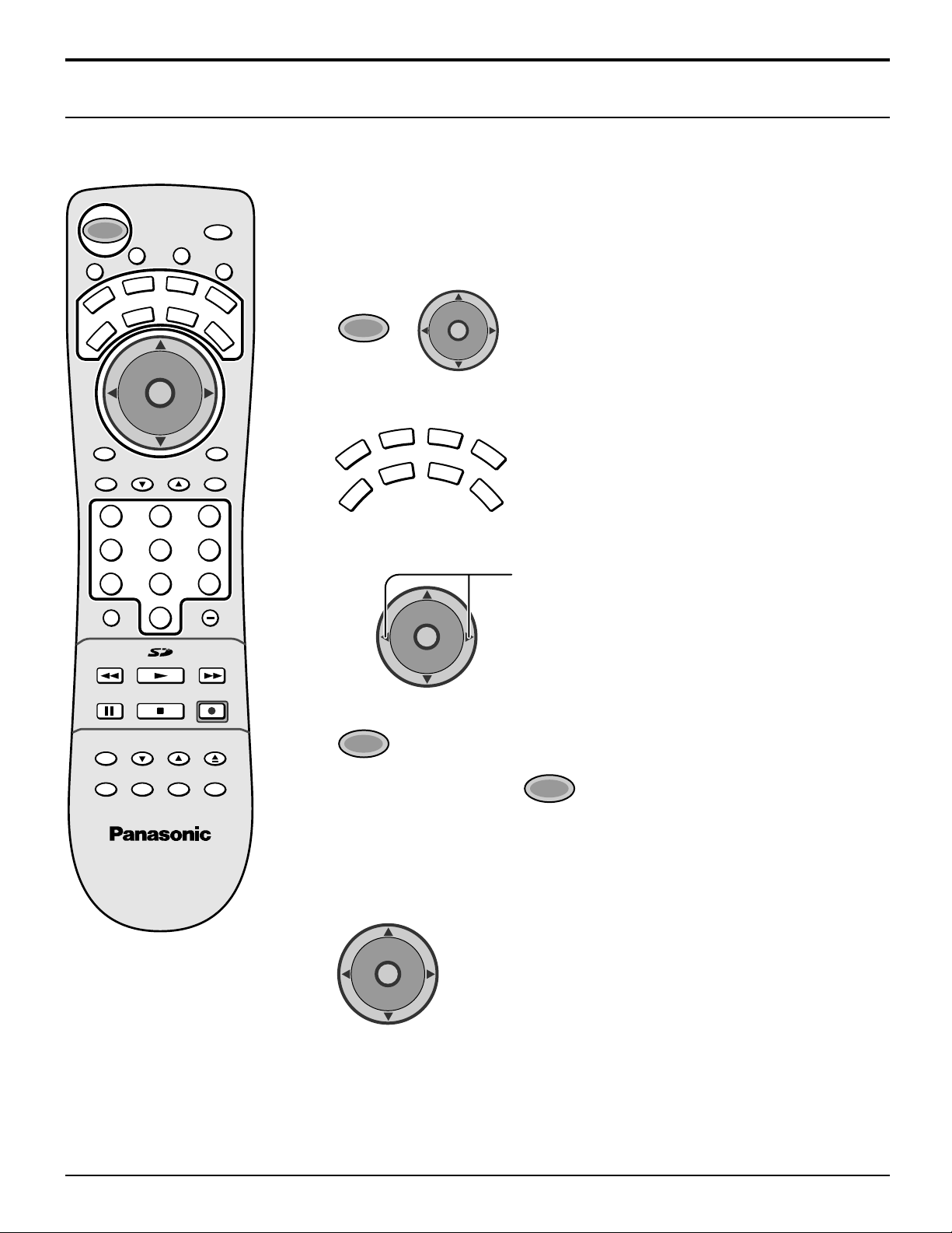
Operating peripheral equipment using the remote control
Programming Without A Code (When the code is not known)
This procedure searches all codes and is called the “sequence method.”
Confirm that the external component is plugged in and on.
1
SAP
T
V
/
V
I
D
E
O
L
I
G
H
T
A
U
X
RCVR
CBL
DBS
O
N
Turn the component off.
2
3
POWER
+
CH
O
I
T
N
C
A
VOL VOL
CH
Press POWER and ACTION together, for at least 5
seconds.
After 5 seconds, all the illuminated mode keys will
begin to flash.
Release the POWER and ACTION key.
U
M
POWER
E
T
VCR
TV
T
C
E
P
S
A
DVD
DTV
CH
I
T
C
A
VOL VOL
PC
MENU
CH
RECALL
PAG EEXIT
GUIDE
123
456
7809
R-TUNE PROG
PIP MIN
REW
FREEZE
TV/VCR
PIP
PIP CH
VCR CH
PLAY
STOPPAUSE
MOVESPLIT
PIP MAX
FF
REC
SEARCH
OPEN/CLOSE
SWAP
AUX
VCR
TV
POWER
DVD
DTV
CBL
CH
O
I
T
N
C
A
VOL VOL
CH
RCVR
DBS
Press the mode key.
The mode key will illuminate steadily, all others will go
out.
Press to move forward to the next code, or to move
backward.
POWER
to test the component. If the procedure was
4
5
6
Press the Remote Control
successful, the component will turn on.
Note:
Repeat the above steps until the component code is found. It may take many
attempts before the correct code is found.
7
CH
O
I
T
N
C
A
VOL VOL
CH
After the code is found, press ACTION to store the code.
Note:
The step and set mode will start from the current device (not the beginning of the
list, except for the first time).
63
Page 64
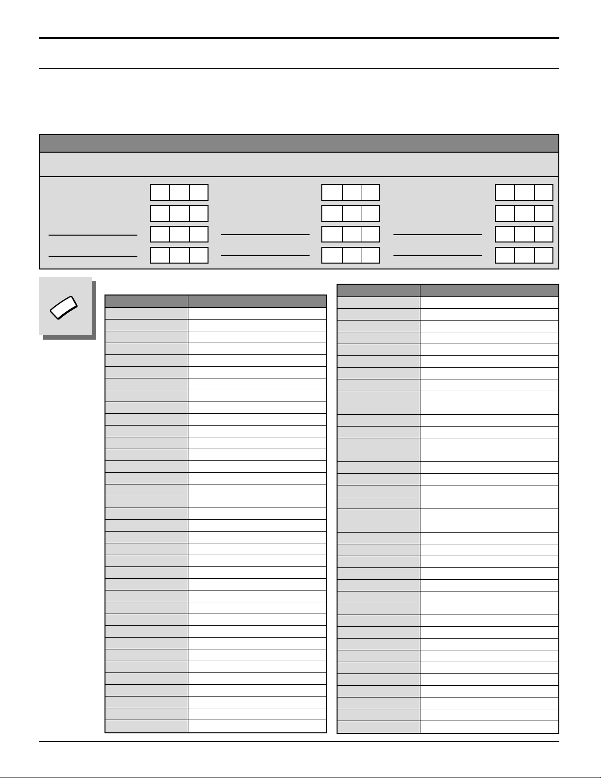
Operating peripheral equipment using the remote control
Infrared Codes Index
The remote control is capable of operating many brands of peripheral equipment. Refer to pages 50 and 51 for programming procedures.
Note: The remote control memory is limited and therefore some models may not operate. The remote control is not
designed to control all features available in all models.
Note: After entering the proper infrared code, press the desired Mode Selection Button on the remote control. Refer to
pages 22 and 57 - 58 for details on operating peripheral equipment using the remote control.
Infrared Remote Codes for Specific Components
Helpful Hint: Write down the code numbers for your components in the space provided below. This will serve as a
handy reference whenever you need to reprogram your remote control.
CABLE
Cable Box
DBS
Digital Broadcast System
VCR
Video Cassette Recorder
RCVR
Receiver or Amplifier
CD
Compact Disc Player
LD
Laser Disc Player
Other Component
Other Component
VCR
Other Component
Other Component
Codes for VCR
Brand Code
Admiral 335
Aiwa 332
Akai 314, 315, 316, 329
Audio Dynamic 311, 339
Bell &Howell 305, 313
Broksonic 320, 326
Canon 323, 325
CCE 343
Citizen 306
Craig 305, 306, 329
Curtis Mathes 324, 345
Daewoo 301, 324, 343
DBX 310, 311, 339
Dimensia 345
Emerson 303, 319, 320, 325, 326, 343
Fisher 305, 307, 308, 309, 313
Funai 320, 326, 334
GE 324, 333, 345
Goldstar 306
Gradiente 334
Hitachi 300, 323, 345
Instant Replay 323, 324
Jensen 339
JVC 310, 311, 334, 339
Kenwood 306, 310, 311, 339
LXI 300, 305, 306, 307, 308, 309
Magnavox 323, 324, 331
Marantz 310, 311, 339
Marta 306
Memorex 309, 324
MGA 338, 340, 341, 347, 348
Minolta 300, 345
Mitsubishi 338, 340, 341, 347, 348
Multitech 304, 347
NEC 310, 311, 334, 339
Olympic 323, 324
Other Component
Other Component
Brand Code
Optimus 306, 321, 328, 335
Orion 320, 326
Panasonic 321, 322, 323, 324
Penney
300, 305, 310, 311, 324, 339, 345
Pentax 300, 311, 345
Philco 320, 323, 324, 326, 331, 343
Philips 323, 324, 331
Pioneer 323
Proscan 300, 301, 302, 323, 324, 331,
333, 345, 346
Quasar 321, 322, 323, 324
Radio Shack 305, 309, 324, 333, 336, 340
RCA 300, 301, 302, 323, 324, 331,
333, 345, 346
Realistic 305, 309, 324, 336, 340
Samsung 302, 304, 333
Sansui 320, 326, 339, 352
Sanyo 305, 309, 313
Scott 301, 302, 304, 309, 320, 326,
338, 340, 347, 348
Sears 300, 305, 306, 307, 308
Sharp 335, 336
Shintom 317
Signature 2000 335
Singer 317
Sony 328, 329, 330
Sylvania 323, 324, 331
Tashiro 306
Tatung 310, 311, 339
Teac 310, 311, 339
Technics 321, 322, 323, 324
Teknika 324
Toshiba 301, 346
Vector Research 311
Wards 306, 309, 335, 336, 344
Yamaha 305, 310, 311, 339
Zenith 306, 344
64
Page 65
DVD
DVD
Operating peripheral equipment using the remote control
Codes for DVD
Brand Code
Denon 100
Ferguson 101
JVC 109
Mitsubishi 105
Nordmende 101
Panasonic 100
Philips 103
Pioneer 102
RCA 101
Codes for CD
Brand Code
Admiral 226
Aiwa 233, 235
Carver 229
Denon 242
Emerson 239
Fisher 205
Harman Kardon 219, 220, 221, 223
Hitachi 207
Jensen 234
JVC 240, 241, 245
Kardon 223
Kenwood 200, 201, 211, 245
LXI/Sears 236
Magnavox 229, 232
Marantz 229
McIntosh 221
Nakamichi 210
Onkyo 214, 215
Brand Code
Saba 101
Samsung 110
Sharp 108
Sony 104
Technics 100
Thomson 101
Toshiba 103
Yamaha 100
Zenith 107
Brand Code
Optimus 208, 218, 220, 222
Panasonic 224, 225, 227
Philips 229, 230
Pioneer 208
Quasar 224, 225, 227
RCA 231, 237, 238, 247
Sansui 210, 246
Sanyo 205
Scott 210, 246
Sharp 242, 243
Sherwood 220
Sony 228
Soundesign 244
Teac 212, 216, 218
Technics 224, 225, 227
Victor 240, 241, 245
Yamaha 202, 203, 204
AUX
AUX
Codes for Personal Video Recorders
Brand Code
Panasonic Replay TV
Philips Tivo 101
Sony Tivo 102
100
Codes for Cassette Deck
Brand Code
Aiwa 223, 224, 225
Denon 231
Fisher 203
Jensen 214
JVC 229, 230
Kenwood 200, 207
Marantz 202
Nakamichi 205
Onkyo 208, 209, 213
Panasonic 216, 218
Brand Code
Philips 222
Pioneer 204
RCA 226, 227, 228
Sansui 205, 210
Sharp 231
Sony 219, 220
Teac 210, 211, 215
Technics 216, 218
Yamaha 201, 202
65
Page 66
Operating peripheral equipment using the remote control
Codes for Receivers
RCVR
CBL
Brand Code
Admiral 120
Aiwa 125, 126
Denon 134, 135, 136
Fisher 104
Garrard 113
Harman Kardon 115, 123
Jensen 129
JVC 132, 133
Kenwood 100, 108
Magnavox 127
Marantz 124
Mclntosh 116
Nakamichi 106
Onkyo 109, 114
Codes for Cable Box
Brand Code
ABC 124
Archer 125, 132
Cableview 105, 132
Citizen 105, 122
Curtis 112, 113
Diamond 124, 125, 132
Eagle 129
Eastern 134
GC Brand 105, 132
Gemini 122
General 111, 119, 120, 121, 122, 123,
Instrument/Jerrold
Hamlin 112, 118, 140, 141, 142, 145
Hitachi 103, 124
Macom 103, 104, 105
Magnavox 133
Memorex 130
Movietime 105, 132
Oak 102, 137, 139
Panasonic 109, 110, 114
Philips 106, 107, 128, 129, 130
Pioneer 101, 116
Pulsar 105, 132
124, 125, 126, 127
Brand Code
Optimus 103, 127, 130, 131
Panasonic 118, 119, 121
Philips 123
Pioneer 105, 107
Quasar 118, 119, 121
RCA 103, 105, 127, 130, 131
Sansui 103, 111, 139
Sharp 134, 137
Sony 122
Soundesign 138
Teac 111, 112, 113
Technics 118, 119, 121
Victor 132, 133
Yamaha 101, 102
Brand Code
Puser 132
RCA 115
Realistic 132
Regal 112, 118, 140, 141, 142, 145
Regency 134
Rembrandt 105, 132, 137
Samsung 105
Scientific Atlanta 111, 112, 113
Slmark 101, 105
Sprucer 105, 110
Stargate 105, 132
Tel eview 101, 105
Texscan 144
Tocom 135
Toshiba 104
Unika 125, 132
Universal 122, 132
Videoway 106
Viewstar 129, 130
Zenith 100, 117
Zenith /Drae 100
Satellite
66
DBS
Codes for DBS
Brand Code
Dish Network 105, 115, 116
(Echostar)
Echo Star 105
Express VU 105, 115
G.E. 106
G.I. 108
(General Instrument)
Gradiente 114
Hitachi 103, 111, 112
HNS (Hughes) 103
Brand Code
Magnavox 101, 102
Panasonic 104
Philips 101, 102
Primestar 108
Proscan 106, 109, 110, 113
RCA 106, 109, 110, 113
Sony 107
Star Choice 103, 108
Toshiba 100
Uniden 101, 102
Page 67
Operating peripheral equipment using the remote control
Mode Operational Key Chart
This chart defines which keys that are operational after programming (if needed), while in the selected remote control
mode TV, DTV, CABLE, DBS, VCR, DVD ...etc.
KEY NAME TV MODE DTV MODE CABLE MODE DBS MODE
POWER
SAP
MUTE
ASPECT
TV/VIDEO
LIGHT
POWER POWER POWER POWER
SAP ON/OFF
-- -
MUTE TV MUTE CBL MUTE TV MUTE
TV ASPECT DTV ASPECT
-
DBS ASPECT
TV INPUT SW TV INPUT SW TV INPUT SW TV INPUT SW
REMOTE BUTTONS REMOTE BUTTONS REMOTE BUTTONS REMOTE BUTTONS
CH
O
I
T
N
C
A
VOL VOL
CH
PC
MENU
RECALL
EXIT
PAG E
GUIDE
123
456
7809
R-TUNE
PROG
REW
PAUSE
STOP
FREEZE
TV/VCR
PIP CH
VCR CH
SEARCH
OPEN/CLOSE
SPLIT
MOVE
SWAP
PLAY
REC
PIP
PIP MAX
FF
PIP MIN
CHANNEL UP/DOWN NAVIGATION UP/DOWN CABLE CHANNEL UP/DOWN DBS NAVIGATION UP/DOWN
ACTION ACTION ENTER DBS ACTION
VOL + /
-
PC-INPUT DTV MENU
NAVIGATION RIGHT/LEFT CABLE VOL + /
-
-
DBS NAVIGATION RIGHT/LEFT
DBS MENU
DISPLAY PROGRAM INFO. TV DISPLAY DBS PROG.INFO
--
-
--
EXIT (EPG)ELECTRONIC
PROGRAM GUIDE
STB PAGE UP/DOWN
GUIDE (EPG)ELECTRONIC
PROGRAM GUIDE
DBS EXIT
-
DBS PAGE UP/DOWN
DBS GUIDE
Select Channel Select Channel Select Channel Select Channel
PREVIOUS CHAN
OR VIDEO MODE
-
PIP MINIMIZE/
MAXIMIZE
SD
PREVIOUS STB CHAN CABLE PREVIOUS DBS PREVIOUS
DTV PROGRAM/DASH
-
DBS PROGRAM/DASH
-- -
-- -
-- - -
-- - -
-
PIP FREEZE
PIP or SPLIT
CHAN UP/DOWN
PIP SEARCH
PIP ON/OFF
SPLIT ON/OFF
MOVE PIP
PIP or SPLIT SWAP
Info (EPG) ELECTRONIC
PROGRAM GUIDE
--
-
--
--
--
--
-- -
VCR RECORD DBS RECORD
TV/DBS SWITCH
TV CHANNEL UP/DOWN DBS CHANNEL UP/DOWN
DBS SEARCH
DBS M-GUIDE
DBS FAV
DBS JUMP
67
Page 68
Operating peripheral equipment using the remote control
KEY NAME VCR MODE RCVR MODE
POWER
SAP
MUTE
ASPECT
TV/VIDEO
LIGHT
CH
O
I
T
N
C
A
VOL VOL
CH
PC
MENU
RECALL
EXIT
PAG E
GUIDE
123
456
7809
R-TUNE
PROG
REW
PLAY
PAUSE
STOP
REC
FREEZE
TV/VCR
PIP CH
VCR CH
SEARCH
OPEN/CLOSE
SPLIT
MOVE
SWAP
PIP
PIP MAX
FF
PIP MIN
POWER POWER POWER POWER POWER POWER POWER
--- - ---
TV MUTE TV MUTE RCVR MUTE TV MUTE TV MUTE RCVR MUTE RCVR MUTE
--- - ---
TV INPUT SW TV INPUT SW
REMOTE BUTTONS REMOTE BUTTONS REMOTE BUTTONS REMOTE BUTTONS REMOTE BUTTONS REMOTE BUTTONS REMOTE BUTTONS
TV CHAN
UP/DOWN
TV ACTION SELECT
TV VOLUME +/
-
-
ONSCREEN VCR
DISPLAY
---
-
---
Select Channel Select Channel Select Channel
-
--- ---
VCR REW/FF
PLAY PLAY PLAY PLAY PLAY PLAY
PAUSE STILL/PAUSE PAUSE PAUSE PAUSE PAUSE
STOP STOP STOP STOP STOP STOP
VCR RECORD
TV/VCR SWITCH
VCR CHANNEL
UP/DOWN
-
--- - ---
--- - ---
--- - ---
--- - ---
(DVD) (CD) (PVR) (VCR2) (TAPE)
-
NAVIGATION
UP/DOWN
NEXT/PREVIOUS
TRACK
-
NAVIGATION
UP/DOWN
DVD MENU
RCVR VOLUME
UP/DOWN
-
DVD DISPLAY TIME FORMAT PVR ENTER
SKIP +/
-
Select Chapter
Number
SKIP +/
-- - - -
Select Track
Number
DVD TITLE NEXT DISK
SKIP SEARCH
<<REW/>>FF
DVD RECORD
SEARCH REW/FF
-
--
DVD CHANNEL
UP/DOWN
RANDOM/
REPEAT
OPEN/CLOSE OPEN/CLOSE
PVR TV/VCR TV INPUT SW TV INPUT SW
PVR
UP/DOWN
TV CHANNEL
UP/DOWN
PVR SELECT TV ACTION
PVR
RIGHT/LEFT
PVR MENU
TV VOLUME +/-RCVR VOLUME +/-RCVR VOLUME +/
---
ONSCREEN VCR
DISPLAY
PVR EXIT
PVR REP. GUIDE
PVR
RELAY ZONES
---
---
-
PVR
RETURN TO LIVE
PVR REW/FF VCR REW/FF
PVR RECORD VCR RECORD
PVR
INSTANT RELAY
PVR CHANNEL
UP/DOWN
PVR
QUICK SKIP
TV/VCR SWITCH
VCR CHANNEL
UP/DOWN
-
TAPE RECORD
RCVR INPUT SW
-
TUNER +/
-
--
--
-
1.... AV1
2.... AV2
3.... AV3
4.... AV4
5.... CD
6.... TUNER
7.... PHONO
8.... TAPE
9.... AUX
DECK A/B
-
TAPE REW/FF SURROUND -/+
-
-
-
-
--
-
OPEN/CLOSE
RCVR CENTER
+/
-
-
DVD/CD MODE AUX MODE
-
68
Page 69
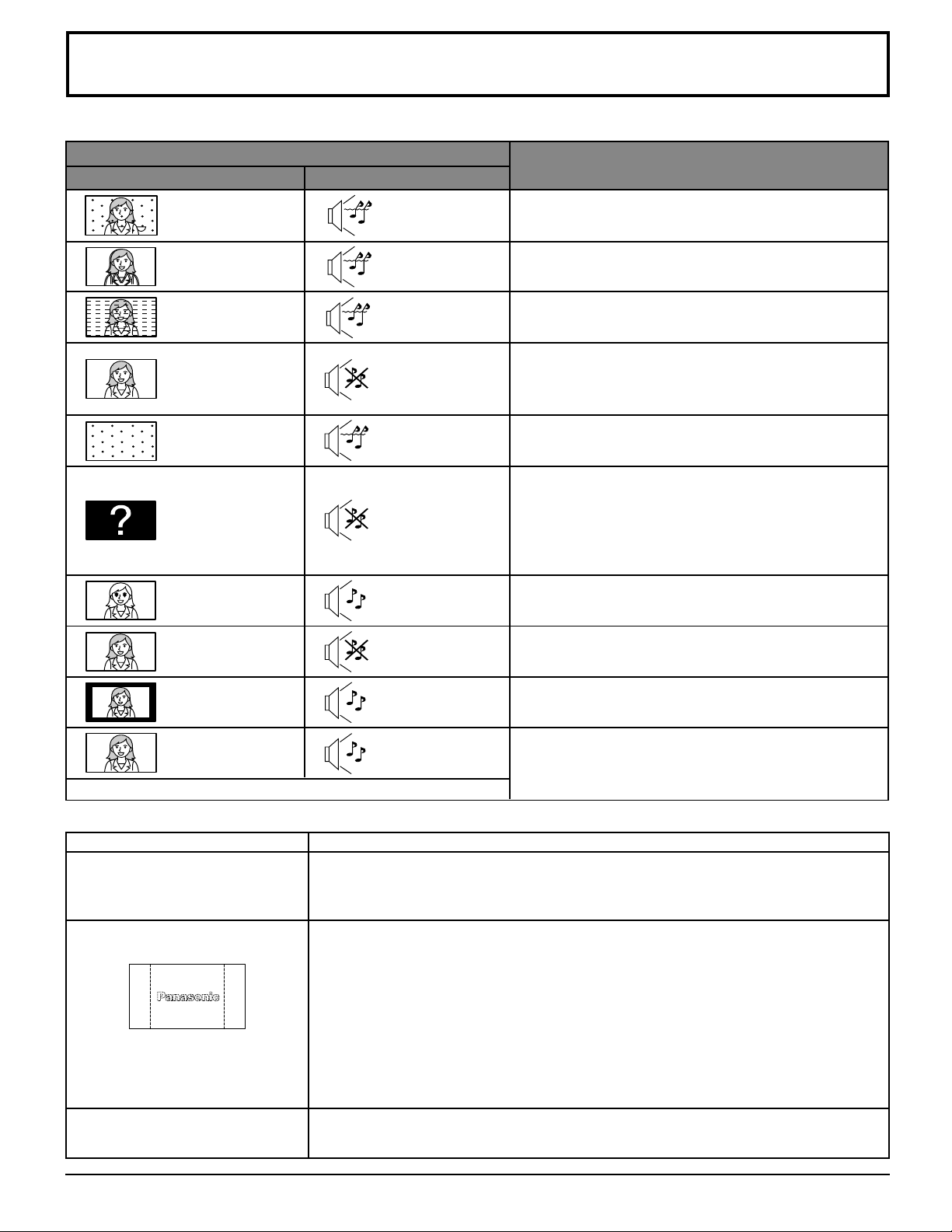
Troubleshooting Chart
Before calling for service, determine the symptoms and follow suggested solutions.
Symptoms
VIDEO AUDIO
VIDEO
Snowy Video
Symptoms
AUDIO
Noisy Audio
Adjust Antenna Location and Connection
Solutions
Solutions
Multiple Image
Interference
Normal Video
No Video with
Snow
No Video /
No PIP
No Color
Normal Video
Black Box on
Screen
Noisy Audio
Noisy Audio
No Audio
Noisy Audio
No Audio
Normal Audio
Wrong Audio
Normal Audio
Adjust Antenna Location and Connection
Check Antenna Lead-in Wire
Move Television away from Electrical Appliances,
Lights, Vehicles and Medical Equipment
Increase Volume
Check Mute
Check Television SPEAKERS on/off
Change Channel
Set TV or Cable Mode Properly
Check Antenna Cables
Check Power Cord is Plugged into Active Outlet
Adjust Brightness and Audio Controls
Change Channel
Check Cable Connections
Program the Remote Control Again
Check Second Video Source Operation
Adjust Color Settings
Change Channel
Check Audio Is Set To Stereo or Mono, Not SAP
Change CC (Closed Captioning) from Text Mode
Normal Video
Intermittent Remote Control Operation
Plasma Display panel
Symptoms
Some parts of the screen do not
light up.
After-images appear
Whirring sounds can be heard
from the display unit.
Normal Audio
The plasma display panel is manufactured using an extremely high level of precision
technology, however, sometimes some parts of the screen may be missing picture
elements or have luminous spots. This is not a malfunction.
Do not allow a still picture to be displayed for an extended period, as this can cause
a permanent after-image to remain on the Plasma TV.
Examples of still pictures include logos, video games, computer images, teletext
and images displayed in 4:3 mode.
Note:
The permanent after-image on the Plasma TV resulting from fixed image use is not
an operating defect and as such is not covered by the Warranty.
This product is not designed to display fixed images for extended periods of time.
The display unit is fitted with a cooling fan to dissipate heat generated during normal
use. The whirring sound is caused by rotation of the fan and is not a malfunction.
Replace Remote Control Batteries
Check
69
Page 70
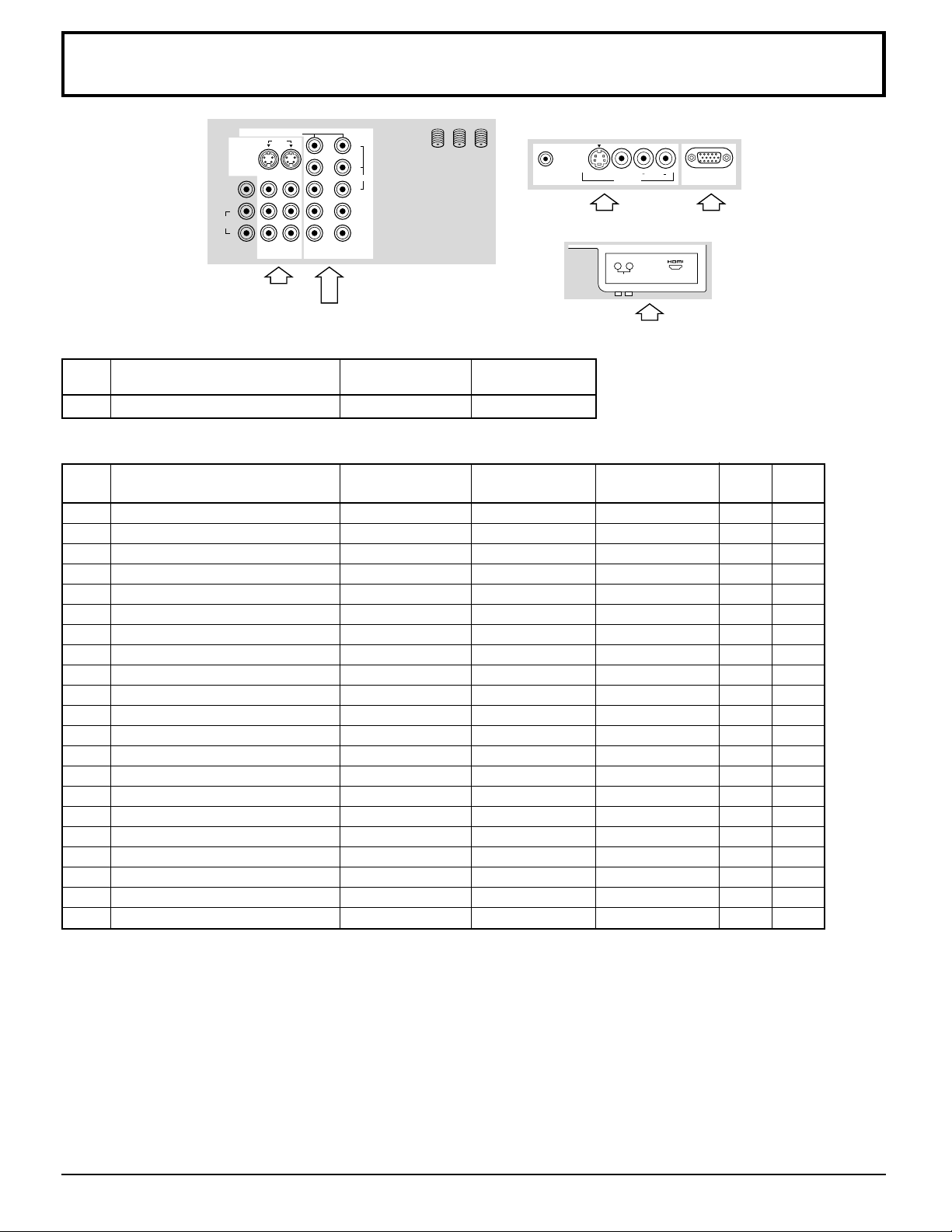
VIDEO/COMPONENT/RGB/PC/HDMI input signals
VIDEO
TO AUDIO
AMP
S VIDEO
PROG OUT
L
R
COMPONENT VIDEO INPUT
INPUT
12
12
P
PR
Y
VIDEO
ANT 1 ANT 2SPLIT
B
OUT
VIDEO input
COMPONENT input
VIDEO input
signal name
horizontal vertical
frequency(kHz) frequency(Hz)
1 NTSC 15.73 59.94
Applicable input signals (∗ mark)
signal name
horizontal vertical
frequency(kHz) frequency(Hz)
1 525 (480) /60i 15.73 59.94
2 525 (480) /60p 31.47 59.94
3 1,125 (1,080) /60i 33.75 59.94
4 640 × 400 @70 31.47 70.00
5 640 × 480 @60 31.47 59.94
6 Macintosh13” (640 × 480) 35.00 66.67
7 640 × 480 @75 37.50 75.00
8 852 × 480 @60 31.50 60.00
9 800 × 600 @60 37.88 60.32
10 800 × 600 @75 46.88 75.00
11 800 × 600 @85 53.67 85.06
12 Macintosh16” (832 × 624) 49.73 74.55
13 1,024 × 768 @60 48.36 60.00
14 1,024 × 768 @70 56.48 70.07
15 1,024 × 768 @75 60.02 75.03
16 1,024 × 768 @85 68.68 85.00
17 Macintosh21” (1,152 × 870) 68.68 75.06
18 1,280 × 1,024 @60 63.98 60.02
19 1,280 × 1,024 @75 79.98 75.03
20 1,280 × 1,024 @85 91.15 85.02
21 1,600 × 1,200 @60 75.00 60.00
HPJ
S-VIDEO
VIDEO input
VIDEO
INPUT 3
L AUDIO R
PC
PC RGB input
LR
AUDIO IN AV IN
HDMI input
COMPONENT PC HDMI
∗∗∗
∗∗∗
∗∗∗
∗
∗
∗
∗
∗
∗
∗
∗
∗
∗
∗
∗
∗
∗
∗
∗
∗
∗
Note: Signals without above specification may not be displayed properly.
70
Page 71
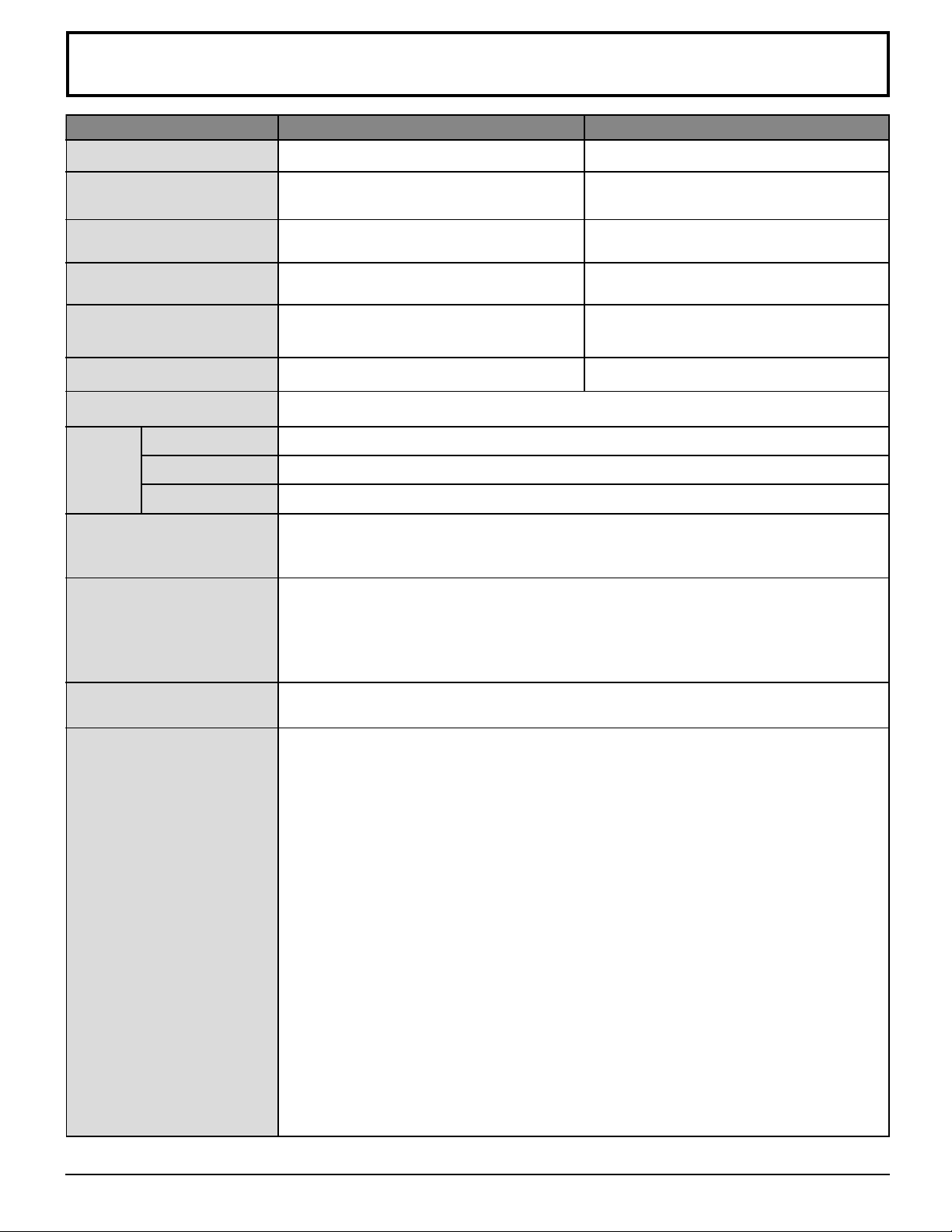
Specifications
Power Source
AC 120 V, 50/60 Hz AC 120 V, 50/60 Hz
TH-42PX20 TH-50PX20
Power Consumption
Plasma Display panel
Screen Size
Dimensions
××
× H
××
××
× D )
××
( W
Mass (Weight)
Channel Capability-181
Speaker
Sound
Audio Output
Headphone
FEATURES
Accessories Supplied
Maximum : 595 W
Stand-by condition : 0.9 W
Drive method : AC type 42-inch ,
16 : 9 aspect ratio
36.22 ” (920 mm) (W) × 20.39 ” (518 mm) (H) ×
41.57 ” (1056 mm) (diagonal)
44.88 ” (1140 mm) × 29.8 ” (757 mm) ×
5.47 ” (139 mm)
90.4 lb. (41 kg) Net
VHF-12 : UHF-56 : Cable-125
Woofer φ 80 mm × 2 , Tweeter 16 mm × 73 mm × 8
26 W [ 5 W + 5 W, 8 W + 8 W ] ( 10 % THD )
M3 (3.5 mm) Jack × 1
Two screen display fuctions 3D Y/C FILTER HDMI
BBE VIVA LINEAR PIP JPEG Viewer
CLOSED CAPTION V-Chip
Remote control Transmitter EUR7603ZB0
AA Battery × 2 Ferrite cores : TH-42PX20 (large × 6, small × 5)
AC Cord TH-50PX20 (large × 7, small × 5)
Pedestal F type Antenna Adaptor (3C-2V × 2, 5C-2V × 2)
Clamper × 2
Maximum : 645 W
Stand-by condition : 0.9 W
Drive method : AC type 50-inch ,
16 : 9 aspect ratio
43.54 ” (1106 mm) (W) × 24.49 ” (622 mm) (H) ×
49.96 ” (1269 mm) (diagonal)
52.32 ” (1329mm) × 34.25 ” (870 mm) ×
5.47 ” (139 mm)
121.3 lb. (55 kg) Net
Operating Conditions
Connection Terminals
Temperature : 34 °F - 104 °F (0 ° – 40 °C)
Humidity : 20 % - 80 % (non-condensing)
RGB input D-SUB 15pin R,G,B / 0.7
HD, VD / 1.0 - 5.0 Vp-p (high impedance)
AV INPUT 1- 3 VIDEO 1.0 Vp-p (75 Ω)
(Phono Jack Type)
S-VIDEO Y :
(Mini DIN 4-pin)
AUDIO L-R 0.5 Vrms
(Phono Jack Type × 2)
AV PROG. OUT VIDEO 1.0 Vp-p (75 Ω)
(Phono Jack Type)
AUDIO L-R 0.5 Vrms
(Phono Jack Type × 2)
TO AUDIO AMP AUDIO L-R 0.5 Vrms
(Phono Jack Type × 2)
COMPONENT VIDEO
INPUT1-2 PB / PR ± 0.35 Vp-p
HDMI
Y 1.0 Vp-p (including synchronization)
AUDIO L-R 0.5 Vrms
(Phono Jack Type × 2)
HDMI type A Connector
AUDIO L-R 0.5 Vrms
(Phono Jack Type × 2)
1.0 Vp-p (75 Ω), C : 0.286 Vp-p (75 Ω)
Vp-p (75 Ω)
Note: Design and Specifications are subject to change without notice. Weight and Dimensions shown are approximate.
71
Page 72

Customer’s Record
The model number and serial number of this product can be found on its back cover. You should note this
serial number in the space provided below and retain this book, plus your purchase receipt, as a permanent
record of your purchase to aid in identification in the event of theft or loss, and for Warranty Service purposes.
Model Number Serial Number
Panasonic Consumer Electronics
Company, Division of Matsushita
Electric Corporation of America
One Panasonic Way Secaucus,
New Jersey 07094
Panasonic Sales Company,
Division of Matsushita Electric
of Puerto Rico Inc. (“PSC”)
Ave. 65 de Infanteria, Km 9.5
San Gabriel Industrial Park,
Carolina, Puerto Rico 00985
Panasonic Canada Inc.
5770 Ambler Drive
Mississauga, Ontario
L4W 2T3
Printed in Japan
MBS0803S1093
 Loading...