

Page 1
Operating Instructions
55-inch model
49-inch model
42-inch model
55-inch model
49-inch model
42-inch model
Functional Manual
FULL HD LCD Display For business use
Model No. TH-55AF1U
TH-49AF1U
TH-42AF1U
TH-55AF1W
TH-49AF1W
TH-42AF1W
This manual is common to all the models regardless of suffixes of the
*
model number.
U : for US, Canada and Mexico
W : for EU, CIS, South East Asia and Middle East Asia
English
Please read these instructions before operating your set
and retain them for future reference.
DPQP1005ZA/X1
Page 2

Dear Panasonic Customer
Welcome to the Panasonic family of customers. We hope that
you will have many years of enjoyment from your new LCD
Display.
To obtain maximum benefit from your set, please read these
Instructions before making any adjustments, and retain them
for future reference.
Retain your purchase receipt also, and note down the model
number and serial number of your set in the space provided
on the rear cover of these instructions.
Visit our Panasonic Web Site http://panasonic.com
English
2
Table of Contents
Before use
●
Illustrations and screens in this Operating Instructions
are images for illustration purposes, and may be
different from the actual ones.
●
Descriptive illustrations in this Operating Instructions
are created mainly based on the 55-inch model.
Important Safety Instructions ..........................5
FCC STATEMENT ..............................................6
Important Safety Notice ................................... 7
Safety Precautions ........................................... 9
Precautions for use ........................................ 12
Accessories ....................................................16
Accessories Supply ·········································· 16
Remote Control Batteries ·································· 17
Kensington security ....................................... 17
Connections .................................................... 18
AC cord connection and fixing ···························· 18
Cable fixing ···················································· 18
Video equipment connection ······························ 19
Before connecting ············································ 20
HDMI 1 and HDMI 2 terminals connection ············· 21
DVI-D IN / DVI-D OUT terminal connection ··········· 22
PC IN terminal connection ································· 23
VIDEO IN terminal connection ···························· 24
COMPONENT/RGB IN terminal connection··········· 25
SERIAL terminal connection ······························· 25
IR IN/IR OUT terminal connection ······················· 28
AUDIO OUT terminal connection ························· 28
USB terminal connection ··································· 28
Using microSD card ········································· 29
USB (OpenPort PLATFORM) terminal connection ··30
Micro-USB terminal connection ··························· 31
Identifying Controls ........................................32
Main unit ························································ 32
Remote Control Transmitter ······························· 34
Basic Controls ................................................ 35
Selecting the input signal ··································· 37
RECALL·························································38
Volume Adjustment ··········································38
Sound mute On / Off ········································· 38
OFF TIMER ···················································· 39
Page 3

Startup of OpenPort PLATFORM ..................40
Startup ·························································· 40
Shutdown ······················································· 40
Basic Operation/Character Input for OpenPort
PLATFORM
Remote Control Transmitter ······························· 41
Buttons on the main unit ···································· 42
USB mouse ···················································· 43
Software keyboard ··········································· 43
USB keyboard ················································· 44
Operation icon ················································· 44
.......................................................41
Home Screen of OpenPort PLATFORM ........45
[SETUP] screen of OpenPort PLATFORM ....46
[INSTALLER] screen of OpenPort PLATFORM
... 47
[TOOLS] screen of OpenPort PLATFORM .... 49
[FAVORITE] screen of OpenPort PLATFORM
Adding the application to [FAVORITE] ·················· 50
Deleting the application from [FAVORITE] ············· 50
[RECENTS] screen of OpenPort PLATFORM
Deleting the application from [RECENTS] ············· 51
[STATUS] screen of OpenPort PLATFORM
... 49
... 51
... 52
Pre-installed Applications of OpenPort
PLATFORM ......................................................53
Pre-installed application list ································ 53
[LAN Control] application ··································· 54
[Settings] application ········································ 55
[CreateShortcut] application ······························· 60
[AppStart] application ········································ 60
[App Server Setting] application ·························· 61
[Shutdown] application ······································ 61
[Updater] application ········································· 61
[SignageBrowser] application ····························· 61
[Version] application ·········································62
[Browser] application ········································ 62
[Camera] application ········································· 62
Android Standard Home Screen of OpenPort
PLATFORM
.......................................................63
ASPECT Controls ........................................... 64
Digital ZOOM ................................................... 65
On-Screen Menu Displays ............................. 66
Adjusting Position .......................................... 68
Auto setup ······················································ 68
Sound Adjustment .......................................... 70
Picture Adjustments ....................................... 71
Picture Profiles ............................................... 73
Saving profiles ················································ 74
Loading profiles ··············································· 75
Editing profiles ················································ 75
Entering profile names ······································ 76
Setup menu ..................................................... 78
Signal ···························································· 78
Screensaver (For preventing image retention)········ 80
Input label ······················································ 81
Power management settings ······························ 81
OpenPort PLATFORM standby ···························83
Wobbling ························································ 83
No activity power off ········································· 83
OSD language ················································ 83
Multi display settings ········································ 84
Set up timer ···················································· 85
USB media player settings ································· 85
Function button settings ···································· 85
Display orientation ··········································· 87
OSD position ·················································· 87
Menu display duration ······································· 87
Menu transparency ·········································· 87
Options Adjustments .....................................88
Using Network Function ................................ 97
Necessary environment for computers to be
connected ····················································97
Example of network connection ·························· 97
Command control ············································ 98
Control Command via LAN ································ 98
PJLink protocol ·············································· 101
Early Warning Software ··································· 102
Multi Monitoring & Control Software ··················· 102
USB Media Player ......................................... 103
Function description ······································· 103
Preparation ··················································· 103
Playing back the files ······································ 104
Starting / ending Media Player ·························· 106
Resume Play function ····································· 106
Data Cloning .................................................107
Copying the display data to the USB memory ······ 107
Copying the USB memory data to the display ······ 108
ID Remote Control Function ........................ 109
Setting the remote control’s ID number ··············· 109
Cancelling the setting of remote control’s ID number
(ID “0”) ························································· 109
English
3
Page 4

Preset Signals ............................................... 110
OpenPort PLATFORM Shutdown ................ 112
Shipping condition ....................................... 113
Troubleshooting ...........................................114
Specifications ............................................... 117
Software License .......................................... 120
English
4
Page 5
WARNING: RISK OF ELECTRIC SHOCK
DO NOT OPEN
Important Safety
WARNING
WARNING: To reduce the risk of electric shock,
do not remove cover or back.
No user-serviceable parts inside. Refer servicing
to qualified service personnel.
The lightning flash with arrow-head within a
triangle is intended to tell the user that parts
inside the product are a risk of electric shock
to persons.
The exclamation point within a triangle
is intended to tell the user that important
operating and servicing instructions are in the
papers with the appliance.
WARNING :
To prevent damage which may result in fire or
shock hazard, do not expose this apparatus to
rain or moisture.
Do not place containers with water (flower vase,
cups, cosmetics, etc.) above the set.
(including on shelves above, etc.)
WARNING :
1) To prevent electric shock, do not remove cover. No
user serviceable parts inside. Refer servicing to
qualified service personnel.
2) Do not remove the grounding pin on the power
plug. This apparatus is equipped with a three pin
grounding-type power plug. This plug will only fit
a grounding-type power outlet. This is a safety
feature. If you are unable to insert the plug into the
outlet, contact an electrician.
Do not defeat the purpose of the grounding plug.
Instructions
1) Read these instructions.
2) Keep these instructions.
3) Heed all warnings.
4) Follow all instructions.
5) Do not use this apparatus near water.
6) Clean only with dry cloth.
7) Do not block any ventilation openings. Install in
accordance with the manufacturer’s instructions.
8) Do not install near any heat sources such as
radiators, heat registers, stoves, or other apparatus
(including amplifiers) that produce heat.
9) Do not defeat the safety purpose of the polarized or
grounding-type plug. A polarized plug has two blades
with one wider than the other. A grounding type plug
has two blades and a third grounding prong. The
wide blade or the third prong are provided for your
safety. If the provided plug does not fit into your
outlet, consult an electrician for replacement of the
obsolete outlet.
10) Protect the power cord from being walked on
or pinched particularly at plugs, convenience
receptacles, and the point where they exit from the
apparatus.
11) Only use attachments / accessories specified by the
manufacturer.
12) Use only with the cart, stand, tripod,
bracket, or table specified by the
manufacturer, or sold with the apparatus.
When a cart is used, use caution when
moving the cart / apparatus combination
to avoid injury from tip-over.
13) Unplug this apparatus during lightning storms or
when unused for long periods of time.
14) Refer all servicing to qualified service personnel.
Servicing is required when the apparatus has been
damaged in any way, such as power-supply cord or
plug is damaged, liquid has been spilled or objects
have fallen into the apparatus, the apparatus has
been exposed to rain or moisture, does not operate
normally, or has been dropped.
15) To prevent electric shock, ensure the grounding pin
on the AC cord power plug is securely connected.
English
5
Page 6

FCC STATEMENT
This equipment has been tested and found to comply
with the limits for a class A digital device, pursuant to
Part 15 of the FCC Rules. These limits are designed
to provide reasonable protection against harmful
interference when the equipment is operated in a
commercial environment. This equipment generates,
uses and can radiate radio frequency energy and, if not
installed and used in accordance with the instructions
manual, may cause harmful interference to radio
communications. Operation of this equipment in a
residential area is likely to cause harmful interference
in which case the user will be required to correct the
interference at his own expense.
FCC CAUTION:
To assure continued compliance, follow the attached
installation instructions and use only the provided
power supply cord. Any changes or modifications
not expressly approved by Panasonic Corp. of North
America could void the user’s authority to operate
this device.
FCC and Industry Canada (IC) RF Exposure
Warning:
This Display is provided with built-in transmitter:
•
Wireless LAN Adapter with FCC ID:
H8N-WLU5150/IC ID:1353A-WLU5150;
This transmitter complies with FCC and IC
•
radiation exposure limits set forth for an
uncontrolled environment for mobile use with
minimum 8 inches (20 cm) spacing requirement
between transmitter and all person’s body
(excluding extremities of hands, wrist and feet)
during wireless modes of operation.
Other third-party wireless transmitters should
•
not be used as they have not been RF exposure
evaluated for use with this Display and may not
comply with RF exposure requirements.
<Only for wireless LAN if capable of transmission in the
5.15 ~ 5.25 GHz frequency band>
This product is restricted to indoor use due to its
operation in the 5.15 to 5.25 GHz frequency range.
IC requires this product to be used indoors for the
frequency range 5.15 to 5.25 GHz to reduce the
potential for harmful interference to co-channel Mobile
Satellite systems. High power radars are allocated as
primary users of the 5.25 to 5.35 GHz and 5.65 to 5.85
GHz bands. These radar stations can cause interference
with and/or damage this product.
Declaration of Verification
Model No.
TH-55AF1U, TH-49AF1U, TH-42AF1U
Responsible Party:
Panasonic Corporation of North America
Two Riverfront Plaza, Newark, New Jersey
07102-5490
Contact Source:
Panasonic System Communications Company of
North America
1-877-655-2357
General Contact:
http://shop.panasonic.com/support
This device complies with Part 15 of the FCC Rules and
all applicable IC RSS standards. Operation is subject
to the following two conditions: (1) This device may not
cause harmful interference, and (2) this device must
accept any interference received, including interference
that may cause undesired operation.
CANADIAN NOTICE:
This Class A digital apparatus complies with
Canadian ICES-003.
WARNING:
Not for use in a computer room as defined in the
•
Standard for the Protection of Electronic Computer/
Data Processing Equipment, ANSI/NFPA 75.
For permanently connected equipment, a readily
•
accessible disconnect device shall be incorporated
in the building installation wiring.
For pluggable equipment, the socket-outlet shall
•
be installed near the equipment and shall be easily
accessible.
English
6
Page 7

Note:
Image retention may occur. If you display a still
picture for an extended period, the image might
remain on the screen. However, it will disappear when
a general moving picture is displayed for a while.
Trademark Credits
Microsoft, Windows, Windows Vista and Internet
•
Explorer are the registered trademarks or trademarks
of Microsoft Corporation in the United States and/or
other countries.
Macintosh, Mac, Mac OS, OS X and Safari are the
•
trademarks of Apple Inc. registered in the United
States and other countries.
PJLink is a registered or pending trademark in Japan,
•
the United States, and other countries and regions.
HDMI, the HDMI Logo, and High-Definition
•
Multimedia Interface are trademarks or registered
trademarks of HDMI Licensing LLC in the United
States and other countries.
microSDHC logo is the trademark of SD-3C, LLC.
•
Google and Android are the trademarks or registered
•
trademarks of Google Inc.
Bluetooth is the trademark or registered trademark of
•
Bluetooth SIG Inc.
Wi-Fi, Wi-Fi Direct and WPS are the trademarks or
•
registered trademarks of Wi-Fi Alliance.
OpenPort PLATFORM is the registered trademark of
•
Panasonic Corporation.
Even if no special notation has been made of company
or product trademarks, these trademarks have been fully
respected.
Important Safety Notice
WARNING
1) To prevent damage which may result in fire or
shock hazard, do not expose this appliance to
dripping or splashing.
Do not place containers with water (flower vase,
cups, cosmetics, etc.) above the set. (including on
shelves above, etc.)
No naked flame sources, such as lighted candles,
should be placed on / above the set.
2) To prevent electric shock, do not remove cover. No
user serviceable parts inside. Refer servicing to
qualified service personnel.
3) Do not remove the earthing pin on the power
plug. This apparatus is equipped with a three pin
earthing-type power plug. This plug will only fit an
earthing-type power outlet. This is a safety feature.
If you are unable to insert the plug into the outlet,
contact an electrician.
Do not defeat the purpose of the earthing plug.
4) To prevent electric shock, ensure the earthing pin
on the AC cord power plug is securely connected.
CAUTION
This appliance is intended for use in environments
which are relatively free of electromagnetic fields.
Using this appliance near sources of strong
electromagnetic fields or where electrical noise may
overlap with the input signals could cause the picture
and sound to wobble or cause interference such as
noise to appear.
To avoid the possibility of harm to this appliance, keep
it away from sources of strong electromagnetic fields.
WARNING:
This equipment is compliant with Class A of CISPR32.
In a residential environment this equipment may
cause radio interference.
WARNING (Australia and New Zealand):
This is a class A product. In a domestic environment
this product may cause radio interference in which
case the user may be required to take adequate
measures.
English
7
Page 8
IMPORTANT INFORMATION
If a display is not positioned in a sufficiently stable
location, it can be potentially hazardous due to falling.
Many injuries, particularly to children, can be avoided
by taking simple precautions such as:
Using cabinets or stands recommended by the
•
manufacturer of the display.
Only using furniture that can safely support the
•
display.
Ensuring the display is not overhanging the edge
•
of the supporting furniture.
Not placing the display on tall furniture (for
•
example, cupboards or bookcases) without
anchoring both the furniture and the display to a
suitable support.
Not standing the displays on cloth or other
•
materials placed between the display and
supporting furniture.
Educating children about the dangers of climbing
•
on furniture to reach the display or its controls.
IMPORTANT: THE MOULDED PLUG
FOR YOUR SAFETY, PLEASE READ THE
FOLLOWING TEXT CAREFULLY.
This display is supplied with a moulded three pin
mains plug for your safety and convenience. A 10
amp fuse is fitted in this plug. Shall the fuse need to
be replaced, please ensure that the replacement fuse
has a rating of 10 amps and that it is approved by
ASTA or BSI to BS1362.
Check for the ASTA mark
or the BSI mark on
the body of the fuse.
If the plug contains a removable fuse cover, you must
ensure that it is refitted when the fuse is replaced.
If you lose the fuse cover the plug must not be used
until a replacement cover is obtained.
A replacement fuse cover can be purchased from
your local Panasonic dealer.
Do not cut off the mains plug.
Do not use any other type of mains lead except the
one supplied with this display.
The supplied mains lead and moulded plug are
designed to be used with this display to avoid
interference and for your safety.
If the socket outlet in your home is not suitable, get it
changed by a qualified electrician.
If the plug or mains lead becomes damaged,
purchase a replacement from an authorized dealer.
WARNING : — THIS DISPLAY MUST BE EARTHED.
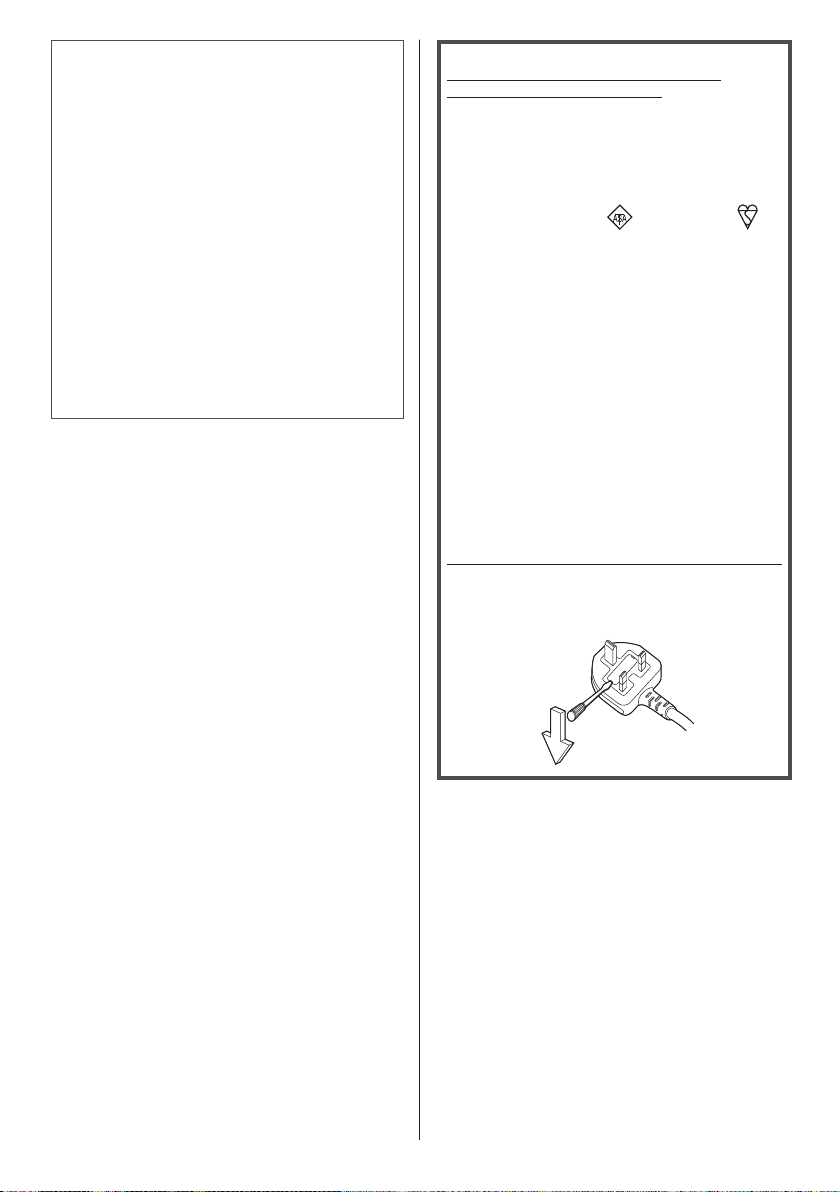
How to replace the fuse.
Open the fuse compartment with a screwdriver and
replace the fuse.
English
8
Page 9
Safety Precautions
WARNING
■ Setup
This LCD Display is for use only with the following
optional accessories.
Use with any other type of optional accessories may
cause instability which could result in the possibility
of injury.
(All of the following accessories are manufactured by
Panasonic Corporation.)
Pedestal
•
TY-ST43PE8
Early Warning Software
•
ET-SWA100 series
Video Wall Manager
•
TY-VUK10
1: Suffix of the part number may differ depending on
*
the license type.
2: Supports Ver1.2 or later.
*
Note
●
The part number of the optional accessories are
subject to change without notice.
When installing the pedestal, read the operating
instructions supplied with it carefully and install properly.
Also, always use the overturn prevention accessories.
We are not responsible for any product damage, etc.
caused by failures in the installation environment for
the pedestal or wall-hanging bracket even during the
warranty period.
Small parts can present choking hazard if accidentally
swallowed. Keep small parts away from young children.
Discard unneeded small parts and other objects,
including packaging materials and plastic bags/sheets to
prevent them from being played with by young children,
creating the potential risk of suffocation.
Do not place the Display on sloped or unstable
surfaces, and ensure that the Display does not hang
over the edge of the base.
The Display may fall off or tip over.
•
Install this unit at a location with minimal vibration
and which can support the weight of the unit.
Dropping or falling of the unit may cause injury or
•
malfunction.
Do not place any objects on top of the Display.
If foreign objects or water get inside the Display, a
•
short-circuit may occur which could result in fire or
electric shock. If any foreign objects get inside the
Display, please consult your local Panasonic dealer.
Transport only in upright position!
Transporting the unit with its display panel facing
•
upright or downward may cause damage to the
internal circuitry.
1
*
2
*
Ventilation should not be impeded by covering
the ventilation openings with items such as
newspapers, table cloths and curtains.
For sufficient ventilation, see page 12.
Caution - For use only with UL Listed Wall Mount
Bracket with minimum weight/load 25.0
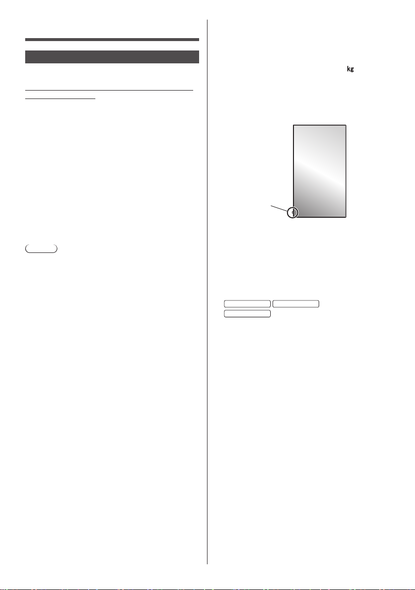
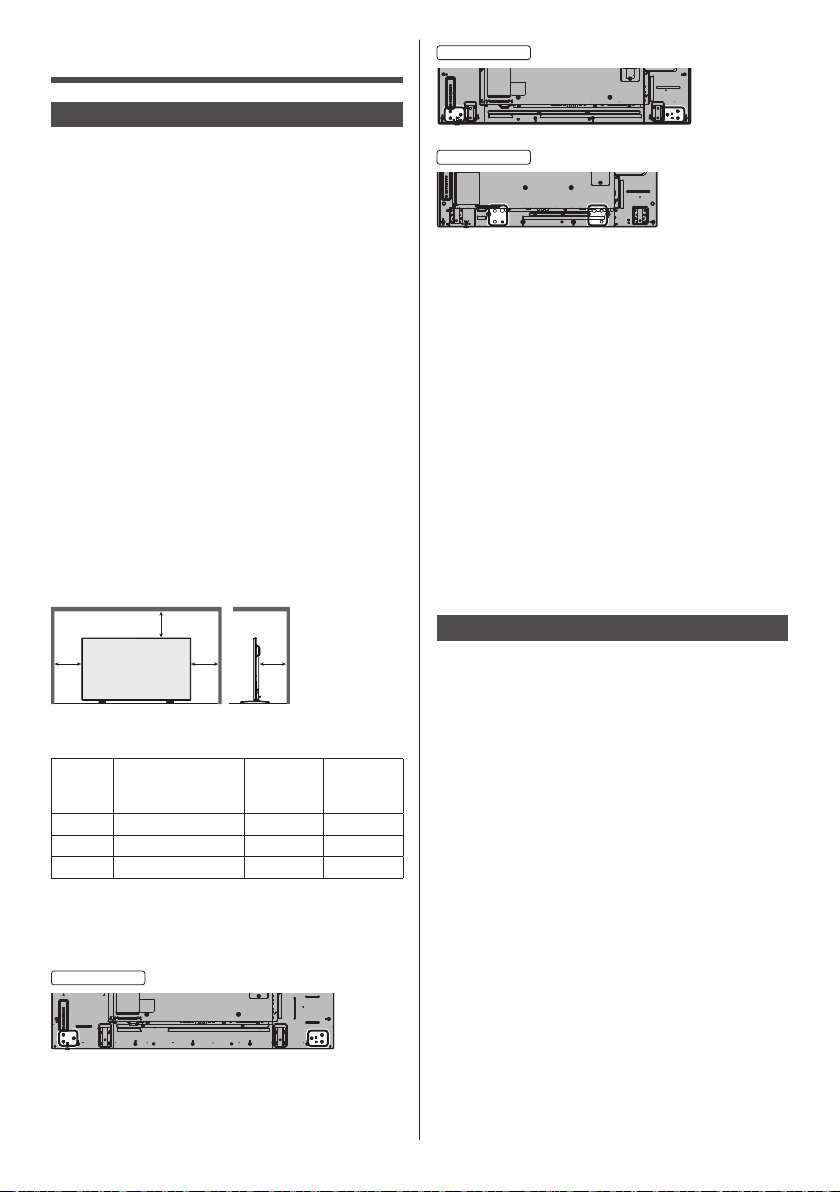
When installing the Display vertically;
When installing the Display vertically, be sure that
the Power Indicator comes to the downside. Heat is
generated and it may cause fire or damage to the
Display.
Power indicator
Cautions for Wall or Pedestal Installation
Wall or Pedestal installation should be performed
•
by an installation professional. Installing the Display
incorrectly may lead to an accident that results in
death or serious injury. Use the optional Pedestal.
(see page 9)
When installing on a wall, a wall hanging bracket that
•
conforms to VESA standards must be used.
55-inch model 49-inch model
42-inch model
(see page 12)
Before installation, be sure to check if the mounting
•
location has enough strength to support the weight
of the LCD display and the wall hanging bracket for
anti drop.
If you terminate the use of the Display on the Wall or
•
Pedestal, ask a professional to remove the Display as
soon as possible.
When mounting the Display on the wall, prevent the
•
mounting screws and power cable from contacting
metal objects inside the wall. An electric shock may
occur if they contact metal objects inside the wall.
Do not install the product to a place where the
product is exposed to direct sunlight.
If the screen is exposed to direct sunlight, the liquid
•
crystal panel may have adverse effect.
: VESA 200×200
: VESA 400×400
(55.2 lbs).
■ When using the LCD Display
The Display is designed to operate on 110 - 127 or
220 - 240 V AC, 50/60 Hz.
Do not cover the ventilation holes.
Doing so may cause the Display to overheat, which
•
can cause fire or damage to the Display.
English
9
Page 10

Do not stick any foreign objects into the Display.
Do not insert any metal or flammable objects into the
•
ventilations holes or drop them onto the Display, as
doing so can cause fire or electric shock.
Do not remove the cover or modify it in any way.
High voltages which can cause severe electric shocks
•
are present inside the Display. For any inspection,
adjustment and repair work, please contact your local
Panasonic dealer.
Ensure that the mains plug is easily accessible.
The mains plug shall be connected to a mains
socket outlet with a protective earthing connection.
Do not use any power supply cord other than that
provided with this unit.
Doing so may cause short-circuit, generates heat,
•
etc., which could cause electric shock or fire.
Do not use the supplied power supply cord with any
other devices.
Doing so could cause electric shock or fire.
•
Securely insert the power supply plug as far as it
will go.
If the plug is not fully inserted, heat may be generated
•
which could cause fire. If the plug is damaged or the
wall socket is loose, they shall not be used.
Do not handle the power supply plug with wet
hands.
Doing so may cause electric shocks.
•
Do not do anything that may damage the power
cable. When disconnecting the power cable, pull on
the plug body, not the cable.
Do not damage the cable, make any modifications
•
to it, place heavy objects on top of it, heat it, place it
near any hot objects, twist it, bend it excessively or
pull it. To do so may cause fire and electric shock. If
the power cable is damaged, have it repaired at your
local Panasonic dealer.
Do not touch the power supply cord or the plug
directly by hand when they are damaged.
Electric shock could occur.
Do not remove covers and NEVER modify the
Display yourself
Do not remove the rear cover as live parts are
•
accessible when it is removed. There are no user
serviceable parts inside. (High-voltage components
may cause serious electrical shock.)
Have the Display checked, adjusted, or repaired at
•
your local Panasonic dealer.
Keep the AAA/R03/UM4 batteries (supplied) and
anti-theft cover of microSD card (see page 29) out of
reach of children. If accidentally swallowed, it will be
harmful to the body.
Please contact a doctor immediately in case you
•
doubt that the child may have swallowed it.
If the Display is not going to be used for any
prolonged length of time, unplug the power supply
plug from the wall outlet.
Picture noise may occur if you connect / disconnect
the cables connected to the input terminals you
are currently not watching, or if you turn the power
of the video equipment on / off, but it is not a
malfunction.
Data or the settings could be lost if the unit is turned
off by disconnecting the power plug, etc., while
OpenPort PLATFORM system is operating.
Generally, when it is operating, be sure to shut down
•
OpenPort PLATFORM system first, and then remove
the power plug, etc. (see page 40)
To prevent the spread of fire, keep
candles or other open flames away from
this product at all times.
10
English
Page 11

CAUTION
If problems or malfunction occur, stop using
immediately.
■ If problems occur, unplug the power supply
plug.
Smoke or an abnormal odour come out from the unit.
•
No picture appears or no sound is heard,
•
occasionally.
Liquid such as water or foreign objects got inside the
•
unit.
The unit has deformed or broken parts.
•
If you continue to use the unit in this condition, it
could result in fire or electric shock.
Turn the power off immediately, unplug the power
•
supply plug from the wall outlet, and then contact the
dealer for repairs.
To cut off the power supply to this Display completely,
•
you need to unplug the power supply plug from the
wall outlet.
Repairing the unit yourself is dangerous, and shall
•
never be done.
To enable to unplug the power supply plug
•
immediately, use the wall outlet which you can reach
easily.
■ Do not touch the unit directly by hand when
it is damaged.
Electric shock could occur.
■ When using the LCD Display
Do not bring your hands, face or objects close to the
ventilation holes of the Display.
Heated air comes out from the ventilation holes at the
•
top of Display will be hot. Do not bring your hands or
face, or objects which cannot withstand heat, close to
this port, otherwise burns or deformation could result.
At least 2 people are required to carry or unpack
this unit.
If this is not observed, the unit may drop, resulting in
•
injury.
Be sure to disconnect all cables before moving the
Display.
If the Display is moved while some of the cables are
•
still connected, the cables may become damaged,
and fire or electric shock could result.
Disconnect the power supply plug from the wall
socket as a safety precaution before carrying out
any cleaning.
Electric shocks can result if this is not done.
•
Clean the power cable regularly to prevent it
becoming dusty.
If dust built up on the power cord plug, the resultant
•
humidity can damage the insulation, which could
result in fire. Pull the power cord plug out from the
wall outlet and wipe the mains lead with a dry cloth.
Do not step on, or hang from the display or the
Pedestal.
They might tip over, or might be broken and it may
•
result in injury. Pay special attention to the children.
Do not reverse the polarity (+ and -) of the battery
when inserting.
Mishandling the battery may cause its explosion
•
or leakage, resulting in fire, injury or damage to
surrounding properties.
Insert the battery correctly as instructed. (see page
•
17)
Remove the batteries from the remote control
transmitter when not using for a long period of time.
The battery may leak, heat, ignite or burst, resulting in
•
fire or damage to surrounding properties.
Do not burn or breakup batteries.
Batteries must not be exposed to excessive heat such
•
as sunshine, fire or the like.
Do not turn the Display upside down.
Do not position the unit with its display panel facing
upright.
English
11
Page 12
Precautions for use
Cautions when installing
Do not set up the Display outdoors.
The Display is designed for indoor use.
•
Environmental temperature to use this unit
When using the unit where it is below 1 400 m (4 593
•
ft) above sea level: 0 °C to 40 °C (32 °F to 104 °F)
When using the unit at high altitudes (1 400 m (4 593
•
ft) and higher and below 2 800 m (9 186 ft) above sea
level): 0 °C to 35 °C (32 °F to 95 °F)
Do not install the unit where it is 2 800 m (9 186 ft)
and higher above sea level.
Failure to do so may shorten the life of the internal
•
parts and result in malfunctions.
Required space for ventilation
When using the pedestal (optional accessory), leave
a space of 10 cm (3
right, and 5 cm (1 31/32”) or more at the rear, and also
keep the space between the bottom of the display and
the floor surface.
If using some other setting-up method (wall-hanging,
etc.), follow the manual of it. (If there is no specific
indication of installation dimension in the installation
manual, leave a space of 10 cm (3
top, bottom, left and right, and 5 cm (1 31/32”) or more at
the rear.)
Minimum distance:
a
About the screws used when using a wall hanging
bracket that conforms to VESA standards
Inch
model
55 400 mm × 400 mm 10 mm M6 (4)
49 400 mm × 400 mm 10 mm M6 (4)
42 200 mm × 200 mm 10 mm M6 (4)
When installing, do not use the screw holes
(situated at the bottom of the display’s back) as
shown in the following figures.
It may damage the LCD panel.
55-inch model
15/16”) or more at the top, left and
15/16”) or more at the
a
a
Screw pitch for
installation
b
Depth of
screw
hole
a: 10 cm
(3
15/16”)
b: 5 cm
31/32”)
(1
Screw
(quantity)
49-inch model
42-inch model
Be careful of the movable structure of the power
indicator and remote control sensor.
As factory default, the power indicator and remote
•
control sensor are stored in the main unit. For normal
use, pull out the remote control sensor from the edge
side of the main unit by operating the lever on the
rear panel. Depending on the setup condition such as
when using the multi display, store the remote control
sensor in the main unit. (see page 32)
Do not grab the liquid crystal panel.
Do not forcibly press the liquid crystal panel, or push
•
it with a pointed object. Applying a strong force to
the liquid crystal panel will cause unevenness of the
screen display, resulting in malfunction.
Depending on the temperature or humidity
conditions, uneven brightness may be observed.
This is not a malfunction.
This unevenness will disappear while applying current
•
continuously. If not, consult the distributor.
Request Regarding Security
When using this product, take safety measures
against the following incidents.
Personal information being leaked via this product
•
Unauthorized operation of this product by a malicious
•
third party
Interfering or stopping of this product by a malicious
•
third party
Take sufficient security measures. (see page 54, 98)
Set a password for the LAN control and restrict the
•
users who can log in.
Make your password difficult to guess as much as
•
possible.
Change your password periodically.
•
Panasonic Corporation or its affiliate companies will
•
never ask for your password directly. Do not divulge
your password in case you receive such inquiries.
The connecting network must be secured by a
•
firewall, etc.
When disposing the product, initialize the data before
•
disposing. [Factory data reset] (see page 59) or
[Shipping] (see page 113 )
About Wireless LANs
●
The advantage of a wireless LAN is that information
can be exchanged between a PC or other such
equipment and an access point using radio waves as
long as you are within range for radio transmissions.
12
English
Page 13

On the other hand, because the radio waves can
travel through obstacles (such as walls) and are
available everywhere within a given range, problems
of the type listed below may occur if security-related
settings are not made.
A malicious third-party may intentionally intercept
•
and monitor transmitted data including the content
of e-mail and personal information such as your ID,
password, and/or credit card numbers.
A malicious third-party may access your personal
•
or corporate network without authorization and
engage in the following types of behaviour.
Retrieve personal and/or secret information
(information leak)
Spread false information by impersonating a
particular person (spoofing)
Overwrite intercepted communications and issue
false data (tampering)
Spread harmful software such as a computer virus
and crash your data and/or system (system crash)
●
Since most wireless LAN adapters or access points
are equipped with security features to take care of
these problems, you can reduce the possibility of
these problems occurring when using this product
by making the appropriate security settings for the
wireless LAN device.
●
Some wireless LAN devices may not be set for
security immediately after purchase. To decrease the
possibility of occurrence of security problems, before
using any wireless LAN devices, be absolutely sure
to make all security-related settings according to the
instructions given in the operation manuals supplied
with them.
Depending on the specifications of the wireless LAN,
a malicious third-party may be able to break security
settings by special means.
Please contact Panasonic if you need help taking
care of security settings or other such.
If you cannot perform security settings for your
wireless LAN by yourself, please contact the
Panasonic Support Center.
●
Panasonic asks customers to thoroughly understand
the risk of using this product without making security
settings, and recommends that the customer
make security settings at their own discretion and
responsibility.
About built-in wireless LAN
CAUTION:
Be aware of the following limits before using the
Wireless LAN Module.
To use the Wireless LAN Module, an access point
•
needs to be obtained.
Do not use the Wireless LAN Module to connect to
•
any wireless network (SSID*) for which you do not
have usage rights. Such networks may be listed as
a result of searches. However, using them may be
regarded as illegal access.
SSID is a name for identifying a particular wireless
*
network for transmission.
Do not subject the Wireless LAN Module to high
•
temperatures, direct sunlight or moisture.
Do not bend, or subject the Wireless LAN Module to
•
strong impacts.
Do not disassemble or alter the Wireless LAN Module
•
in any way.
Do not attempt to install the Wireless LAN Module in
•
any incompatible device.
Do not remove the Wireless LAN Module from the
•
host product during operations.
Data transmitted and received over radio waves may
•
be intercepted and monitored.
To avoid malfunctions caused by radio wave interface,
•
keep the host product away from the devices such
as other wireless LAN devices, microwaves and the
devices that use 2.4 GHz and 5 GHz signals when
using the Wireless LAN Module.
When noises occur due to the static electricity,
•
etc., the host product might stop operating for the
protection of the devices. In this case, turn the host
product Off with Mains power On / Off switch, then
turn it On again.
Depending on the area, this Wireless LAN Module
•
may not be available.
Notes on Using Wireless Connection
Wireless connection function of the Display uses
radio waves in the 2.4 GHz and 5 GHz bands.
A radio station license is not required, but be sure to
read and fully understand the following items before
use.
Do not use near other wireless equipment.
●
The following equipment may use radio waves in the
same band as the Display.
When the Display is used near these devices,
radio wave interference may make communication
impossible, or the communication speed may become
slower.
Microwave ovens, etc.
•
Industrial, chemical and medical equipment, etc.
•
In-plant radio stations for identifying moving objects
•
such as those used in factory manufacturing lines,
etc.
Designated low-power radio stations
•
If at all possible, avoid the use of cellular phones, TV
sets or radios near the Display.
●
Cellular phones, TV sets, radios and similar devices
use different radio bands from the Display, so
there is no effect on wireless communication or
the transmission and reception of these devices.
However, radio waves from the Display may produce
audio or video noise.
Wireless communication radio waves cannot
penetrate steel reinforcements, metal, concrete, etc.
●
Communication is possible through walls and floors
made from materials such as wood and glass (except
glass containing wire mesh), but not through walls
and floors made from steel reinforcements, metal,
concrete, etc.
English
13
Page 14
Avoid using the Display in locations prone to static
UAE
UAE-TRA
REGIS
o:
2
o:
0052708/10
e
I
s
D
7
T
electricity.
●
If the Display is used in a location prone to static
electricity, such as on a carpet, the wireless LAN or
wired LAN connection may be lost.
●
If this happens, eliminate the source of static
electricity or electromagnetic noise and reconnect to
the wireless LAN or wired LAN.
Using the Display outside the country
●
It is forbidden to take the Display outside the country
or region where you purchased it, so use it only in
the said country or region. Also, note that depending
on countries or regions there are restrictions on the
channels and frequencies at which you can use the
wireless LAN.
Available wireless LAN channels
●
The channels (frequency range) that can be used
differ according to the country or region. Refer to the
table below.
Country or region: Global
Channels used: Passive scanning
Standard
Frequency band
(Centre frequency)
IEEE802.11a/n 5.180 GHz - 5.825 GHz
IEEE802.11b/g/n 2.412 GHz - 2.472 GHz
The frequency and channel differ depending on the
•
country.
The passive scanning is performed by changing radio
•
to the channel being scanned in each country.
Please use the wireless LAN feature in compliance
•
with the laws of each country.
For Mexico:
Operation of this equipment is subject to the following
two conditions:
(1) this equipment might not have a harmful
interference and
(2) this equipment must accept any interference,
including one that might cause it to malfunction
For Jamaica:
This product contains Type Approved Modules by
•
Jamaica.
LCD Display
Declaration of Conformity (DoC)
“Hereby, Panasonic Corporation declares that this
Display is in compliance with the essential requirements
and other relevant provisions of the Directive 1999/5/
EC.”
If you want to get a copy of the original DoC of this
Display, please visit the following website:
http://www.doc.panasonic.de
Authorized Representative:
Panasonic Testing Centre
Panasonic Service Europe, a division of Panasonic
Marketing Europe GmbHn
Winsbergring 11, 22525 Hamburg, Germany
This Display is intended to be used in the following
countries.
Albania, Austria, Belgium, Bulgaria, Cyprus, Czech
Republic, Denmark, Estonia, Finland, France, Germany,
Greece, Hungary, Italy, Iceland, Latvia, Lithuania,
Luxembourg, Malta, Netherlands, Norway, Poland,
Portugal, Romania, Slovakia, Slovenia, Spain, Sweden,
Switzerland, Turkey, United Kingdom
The wireless LAN feature of this Display shall
exclusively be used inside buildings.
TERED N
ER0081229/1
DEALER N
DA
Singapor
Complies with
DA Standard
B0101
hailand
“เครื่องโทรคมนาคมและอุปกรณ์นี้มีความสอดคล้องตาม
มาตรฐานทางเทคนิค เลขที่ กทช. มท. 1012-2551”
Notes on Using Wired LAN
When setting up the Display at a place, where
electric statistic occurs often, take a sufficient
antistatic measure before start using.
When the Display is used at a location, where static
•
electricity occurs often, such as on a carpet, a wired
LAN communication is disconnected more often.
In that case, remove static electricity and the noise
source that may cause problems with an antistatic
mat, and re-connect the wired LAN.
In rare cases, the LAN connection is disabled due
•
to static electricity or noise. In that case, turn off the
power of the Display and the connected devices once
and then re-turn on the power.
The Display may not work properly due to strong
radio wave from the broadcast station or the radio.
If there is any facility or equipment, which outputs
•
strong radio wave, near the installation location, set
up the Display at a location sufficiently far from the
source of the radio wave. Or, wrap the LAN cable
connected to the LAN terminal by using a piece of
metal foil or a metal pipe, of which is grounded at
both ends.
14
English
Page 15

Cleaning and maintenance
The front of the display panel has been specially
treated. Wipe the surface of the display panel gently
using only a cleaning cloth or a soft, lint-free cloth.
If the surface is particularly dirty, wipe with a soft,
•
lint-free cloth which has been soaked in pure water or
water in which neutral detergent has been diluted 100
times, and then wipe it evenly with a dry cloth of the
same type until the surface is dry.
Do not scratch or hit the surface of the panel with
•
fingernails or other hard objects, otherwise the
surface may become damaged. Furthermore, avoid
contact with volatile substances such as insect
sprays, solvents and thinner, otherwise the quality of
the surface may be adversely affected.
If the cabinet becomes dirty, wipe it with a soft, dry
cloth.
If the cabinet is particularly dirty, soak the cloth in
•
water to which a small amount of neutral detergent
has been added and then wring the cloth dry. Use this
cloth to wipe the cabinet, and then wipe it dry with a
dry cloth.
Do not allow any detergent to come into direct contact
•
with the surface of the Display. If water droplets get
inside the unit, operating problems may result.
Avoid contact with volatile substances such as insect
•
sprays, solvents and thinner, otherwise the quality of
the cabinet surface may be adversely affected or the
coating may peel off. Furthermore, do not leave it for
long periods in contact with articles made from rubber
or PVC.
Usage of a chemical cloth
Do not use a chemical cloth for the panel surface.
•
Follow the instructions for the chemical cloth to use it
•
for the cabinet.
Disposal
When disposing the product, ask your local
authority or dealer about the correct methods of
disposal.
For USA-California Only
This product contains a CR Coin Cell Lithium Battery
which contains Perchlorate Material - special handling
may apply.
See www.dtsc.ca.gov/hazardouswaste/perchlorate
English
15
Page 16
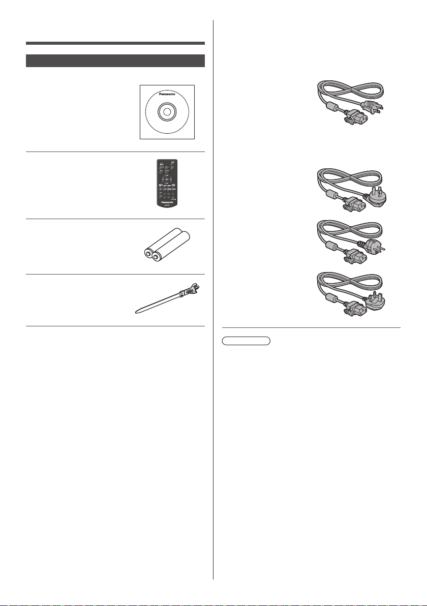
Accessories
Accessories Supply
Check that you have the accessories and items shown
Operating Instructions
(CD-ROM × 1)
Remote Control Transmitter
× 1
●
DPVF1203ZA
Batteries for the Remote
Control Transmitter
(AAA/R03/UM4 type × 2)
Clamper × 3
●
TZZ00000694A
Power supply cord
(Approx. 2 m)
TH-55AF1U
TH-49AF1U
TH-42AF1U
●
1JP155AF1U
TH-55AF1W
TH-49AF1W
TH-42AF1W
●
1JP155AF1W
●
2JP155AF1W
●
3JP155AF1W
16
English
Attention
●
Store small parts in an appropriate manner, and keep
them away from young children.
●
The part numbers of accessories are subject to
change without notice. (The actual part number may
differ from the ones shown above.)
●
In case you lost accessories, please purchase them
from your dealer. (Available from the customer
service)
●
Dispose the packaging materials appropriately after
taking out the items.
Page 17
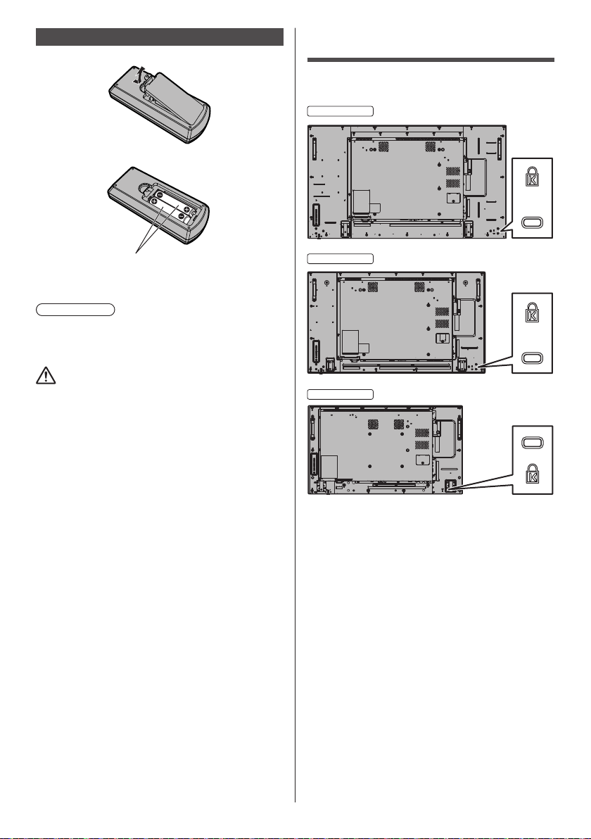
Remote Control Batteries
55-inch model
42-inch model
1. Pull and hold the hook, then open the battery cover.
2. Insert batteries - note correct polarity (+ and -).
Kensington security
The security slot of this unit is compatible with the
Kensington security slot.
AAA/R03/UM4 type
3. Replace the cover.
Helpful Hint
●
For frequent remote control users, replace old
batteries with Alkaline batteries for longer life.
Precaution on battery use
Incorrect installation of the batteries can cause battery
leakage and corrosion that will damage the remote
control transmitter.
Disposal of batteries should be in an environmentfriendly manner.
Observe the following precaution:
1. Batteries shall always be replaced as a pair. Always
use new batteries when replacing the old set.
2. Do not combine a used battery with a new one.
3. Do not mix battery types (example: “Zinc Carbon” with
“Alkaline”).
4. Do not attempt to charge, short-circuit, disassemble,
heat or burn used batteries.
5. Battery replacement is necessary when remote
control acts sporadically or stops operating the
Display set.
6. Do not burn or breakup batteries.
7. Batteries must not be exposed to excessive heat such
as sunshine, fire or the like.
49-inch model
English
17
Page 18
Connections
55-inch model
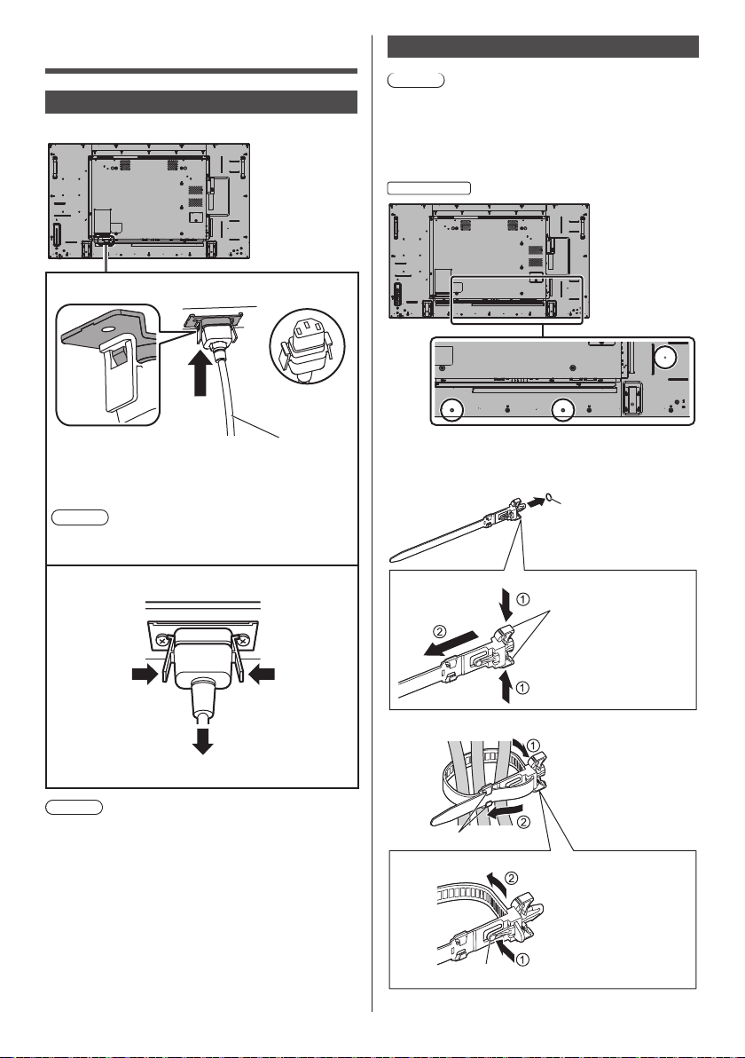
AC cord connection and fixing
Back of the unit
AC cord fixing
AC cord (supplied)
Plug the connector into the display unit.
Plug the connector until it clicks.
Note
●
Make sure that the connector is locked on both the
left and right sides.
Unplug the AC cord
Cable fixing
Note
●
3 clampers are supplied with this unit. Fix the cables
at 3 locations using the holes for clampers as shown
below.
If you need more clampers, purchase them from your
dealer. (Available from the customer service)
●
The positions of the holes are the same for 42-inch
and 49-inch models.
1. Attach the clamper
hole
Insert the clamper in a
hole.
To remove from
the unit:
snaps
Keep pushing both side
snaps and pull out the
clamper.
Unplug the connector pressing the two knobs.
Note
●
When disconnecting the AC cord, be absolutely sure
to disconnect the AC cord plug at the socket outlet
first.
●
The supplied AC cord is for this unit exclusive use. Do
not use this for other purposes.
English
18
2. Bundle the cables
Set the tip in the hooks
and tighten.
hooks
To loosen:
Keep pushing the knob
and pull out the tip.
knob
Page 19
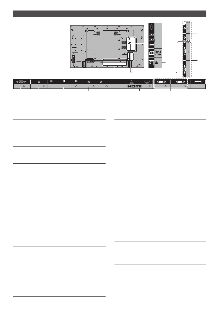
Video equipment connection
Micro-USB
11
USB
OpenPort
12
PLATFORM
13
LAN
14
B/P
B/CB
PC IN
AUDIO1 IN AUDIO2 IN
1 2 3 4 5 6 7 8
R/PR/CR
COMPONENT/RGB/VIDEO IN
1 PC IN: PC Input Terminal
Connect to video terminal of PC,
video equipment with “YP
YCBCR” or “RGB” output.
(see page 23)
2 AUDIO1 IN: Audio input terminal shared
with DVI-D IN and PC IN
(see page 22, 23)
3 COMPONENT /
RGB /
VIDEO IN:
COMPONENT / RGB Video
Input Terminal (R/P
CB, G/Y)
Connect to video equipment
with “YP
output.
(see page 25)
Composite Video Input
Terminal (VIDEO)
Connect to video equipment with
Composite signal output.
(see page 24)
4 AUDIO2 IN: Audio Input Terminal shared
with COMPONENT/RGB IN and
VIDEO IN
(see page 24, 25)
5 AUDIO OUT: Analogue Audio Output
Terminal
Connect to audio equipment with
analogue audio input terminal.
(see page 28)
6 AV IN
(HDMI 1,
HDMI 2):
HDMI Input Terminal
Connect to video equipment such
as VCR or DVD player, etc.
(see page 21)
G/Y/VIDEO
BPR / YCBCR” or “RGB”
AUDIO OUT
BPR /
R/CR, B/PB/
DVI-D IN DVI-D OUT
AV IN
7 DVI-D IN,
DVI-D OUT:
DVI-D Input / Output Terminal
Connect to video equipment
with DVI-D output. Also, when
displaying the picture by daisy
chaining multiple displays,
connect to the other display
(DVI-D OUT).
The DVI-D output function is
enabled only when the picture is
displayed via DVI-D IN.
(see page 22)
8 USB: USB Terminal
Connect the USB memory to use
[USB media player]. Also, this
can be used to supply power of
up to 5V/1A to an external device
when the picture is displayed.
(see page 28)
9 IR IN, IR OUT: Infrared Signal Input / Output
Terminal
Use this when operating more
than one display with one remote
control.
(see page 28)
10 SERIAL IN,
SERIAL OUT:
SERIAL Input / Output Terminal
Control the Display by connecting
to PC.
(see page 25)
IR IN
IR OUT
SERIAL
IN
SERIAL
OUT
9
10
USB
English
19
Page 20

11 Micro-USB: Micro-USB Terminal
By connecting the unit to the PC
using the Micro-USB cable, data
in the storage of the OpenPort
PLATFORM system can be read
or written from the PC.
(see page 31)
12 USB (OpenPort
PLATFORM):
13 microSD : microSD card slot
14 LAN: LAN Terminal
USB Terminal for OpenPort
PLATFORM
Used by connecting a USB
memory as external storage for
OpenPort PLATFORM system.
(see page 30)
With OpenPort PLATFORM input,
it is also possible to connect and
use USB devices such as a USB
mouse, a USB keyboard, etc.
(see page 43, 44)
Used by attaching a microSD
card as external storage for
OpenPort PLATFORM system.
(see page 29)
Control the Display by connecting
to Network.
(see page 97)
With OpenPort PLATFORM input,
it is possible to display WEB
pages or download applications
from the server. (see page 48,
62)
Before connecting
●
Before connecting cables, carefully read the operating
instructions for the external device to be connected.
●
Turn off the power of all devices before connecting
cables.
●
Take note of the following points before connecting
the cables. Failure to do so may result in
malfunctions.
When connecting a cable to the unit or a device
•
connected to the unit itself, touch any nearby
metallic objects to eliminate static electricity from
your body before performing work.
Do not use unnecessarily long cables to connect
•
a device to the unit or to the unit body. The
longer the cable, the more susceptible to noise it
becomes. Since using a cable while it is wound
makes it act like an antenna, it is more susceptible
to noise.
When connecting cables, connect GND first, then
•
insert the connecting terminal of the connecting
device in a straight manner.
●
Acquire any cable necessary to connect the external
device to the system that is neither supplied with the
device nor available as an option.
●
If the outer shape of the plug of a connection cable is
large, it may come in contact with the periphery such
as a back cover or the plug of an adjacent connection
cable. Use a connection cable with the suitable plug
size for the terminal alignment.
●
If video signals from video equipment contain too
much jitter, the images on the screen may wobble.
In this case, a time base corrector (TBC) must be
connected.
●
When the sync signals output form PC or video
equipment are disturbed, for example, when changing
settings of video output, the colour of the video may
be disturbed temporarily.
●
The unit accepts Composite video signals, YC
YPBPR signals, analogue RGB signals and digital
signals.
●
Some PC models are not compatible with the unit.
●
Use cable compensator when you connect devices to
the unit using long cables. Otherwise the image may
not display properly.
●
Refer to “Preset Signals” (see page 110 ) for the types
of video signals that can be displayed with the unit.
BCR/
20
English
Page 21
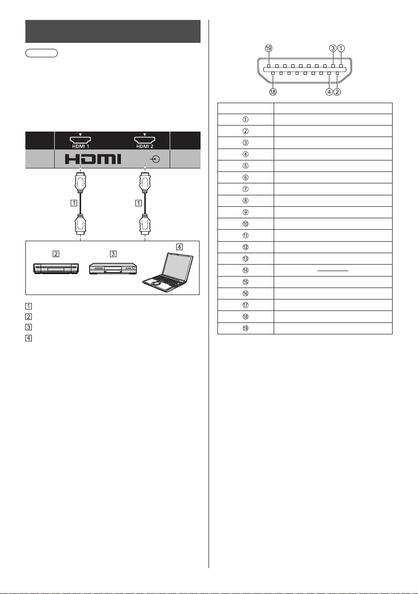
HDMI 1 and HDMI 2 terminals connection
Note
●
Video equipment and HDMI cable shown are not
supplied with this unit.
●
Some HDMI equipment may not be able to display
picture.
●
For audio, it is also possible to use AUDIO1 IN or
AUDIO2 IN terminal input. (For [Audio input select]
function, see page 92.)
AV IN
HDMI cable (commercially available)
Video Cassette Recorder
DVD Player
PC
Pin assignments and signal names for HDMI
Terminal
Pin No. Signal name
T.M.D.S Data2+
T.M.D.S Data2 Shield
T.M.D.S Data2-
T.M.D.S Data1+
T.M.D.S Data1 Shield
T.M.D.S Data1-
T.M.D.S Data0+
T.M.D.S Data0 Shield
T.M.D.S Data0-
T.M.D.S Clock+
T.M.D.S Clock Shield
T.M.D.S Clock-
CEC
SCL
SDA
DDC/CEC Ground
+5V DC
Hot Plug Detect
English
21
Page 22
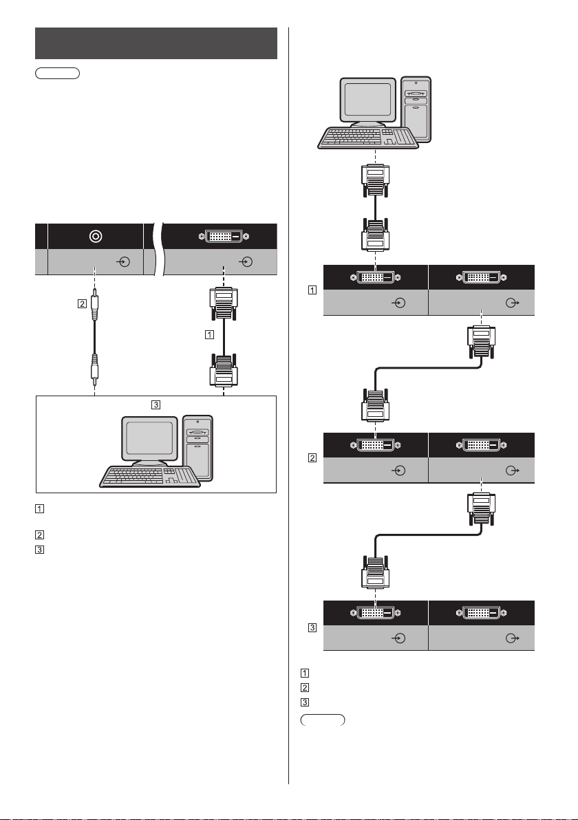
DVI-D IN / DVI-D OUT terminal
AUDIO1 IN
DVI-D IN
connection
Note
●
Video equipment and cables shown are not supplied
with this unit.
●
Use the DVI-D cable complying with the DVI
standard. Image deterioration may occur depending
on the length or the quality of the cable.
●
DVI-D IN terminal is for Single Link only.
●
For audio, it is also possible to use AUDIO2 IN
terminal input. (For [Audio input select] function, see
page 92.)
Shared with PC IN.
Daisy chain connection
It is possible to daisy chain multiple displays when
displaying the picture on multi screen, etc.
DVI-D IN DVI-D OUT
DVI-D video cable (Within 5 m) (commercially
available)
Stereo mini plug (M3) cable (commercially available)
PC with DVI-D video out
English
22
DVI-D IN DVI-D OUT
DVI-D IN DVI-D OUT
First display
Second display
Third display
Note
●
It is possible to daisy chain up to 10 displays.
However, the number of connectable displays may be
limited depending on the cables, signals, the devices
used, etc.
Page 23
●
When inputting HDCP signal, it is possible to daisy
chain up to 8 displays.
●
The DVI-D output function is enabled when the
picture is displayed via DVI-D IN. When using the
daisy-chain connection method, all the displays
should be in the state where the picture is displayed
via DVI-D IN.
Pin assignments and signal names for DVI-D
Input/Output
Pin No. Signal Name
T.M.D.S. data 2-
T.M.D.S. data 2+
T.M.D.S. data 2 shield
DDC clock
DDC data
T.M.D.S. data 1-
T.M.D.S. data 1+
T.M.D.S. data 1 shield
+5 V DC
GND (Ground)
Hot plug detect
T.M.D.S. data 0-
T.M.D.S. data 0+
T.M.D.S. data 0 shield
T.M.D.S. clock shield
T.M.D.S. clock+
T.M.D.S. clock-
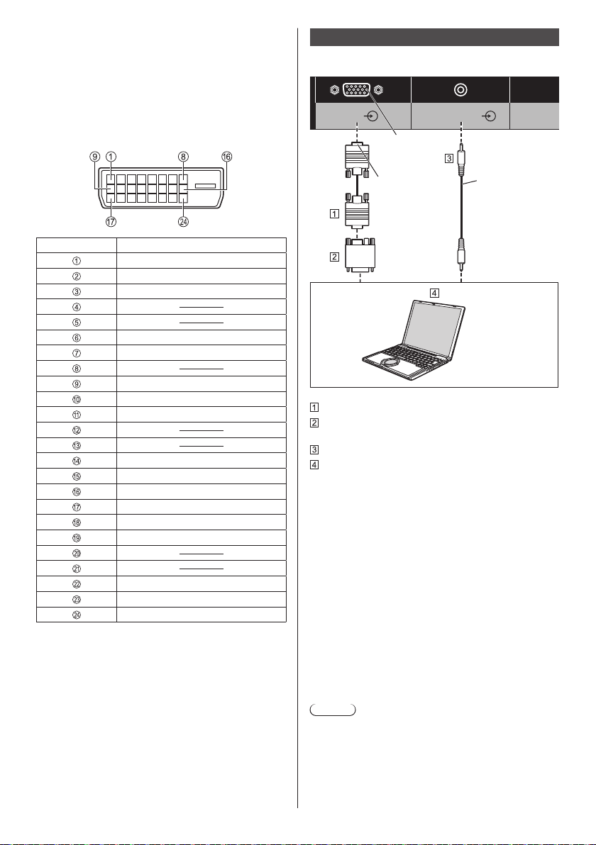
PC IN terminal connection
Shared with DVI-D IN.
AUDIO1 INPC IN
(Female)
(Male)
Mini D-sub 15p cable (commercially available)
Conversion adapter (if necessary) (commercially
available)
Stereo mini plug (M3) cable (commercially available)
PC
The type of computer signal that can be connected
●
With regard to the typical PC input signals that
are described in “Preset Signals” (see page 110 ),
adjustment values such as for the standard picture
positions and sizes have already been stored in this
unit.
(Computer signals which can be input are those with
a horizontal scanning frequency of 30 to 110 kHz and
vertical scanning frequency of 48 to 120 Hz.)
●
The display resolution is a maximum of 1 440 × 1 080
dots when the aspect mode is set to [4:3], and 1 920
× 1 080 dots when the aspect mode is set to [16:9].
If the display resolution exceeds these maximums, it
may not be possible to show fine detail with sufficient
clarity.
●
In [ENGLISH(US)] OSD language, [16:9] is displayed
as [FULL].
Note
●
The PC IN terminal is DDC2B-compatible. If the
computer being connected is not DDC2B-compatible,
you will need to make setting changes to the
computer at the time of connection.
●
There is no need to use an adapter for computers
with DOS/V compatible Mini D-sub 15P terminal.
Stereo mini plug
(M3)
Connect a cable
which matches
the audio output
terminal on the
computer.
(commercially
available)
English
23
Page 24
●
The computer shown in the illustration is for example
purposes only.
●
Additional computer, cables and conversion adapter
shown are not supplied with this set.
●
Do not set the horizontal and vertical scanning
frequencies for PC signals which are above or below
the specified frequency range.
●
Component Input is possible with the pin 1, 2, 3 of the
Mini D-sub 15P Connector.
●
Change the [Component/RGB-in select] setting in
the [Signal] menu to [Component] (when Component
signal connection) or [RGB] (when RGB signal
connection). (see page 78)
●
For audio, it is also possible to use AUDIO2 IN
terminal input. (For [Audio input select] function, see
page 92.)
Pin assignments and signal names for PC Input
Terminal (Mini D-sub 15P)
45
10
15 14 13 12 11
Pin No. Signal Name
R (PR/CR)
G (Y)
B (PB/CB)
NC (not connected)
GND (Ground)
GND (Ground)
GND (Ground)
GND (Ground)
+5 V DC
GND (Ground)
NC (not connected)
SDA
HD/SYNC
VD
SCL
1
2
67839
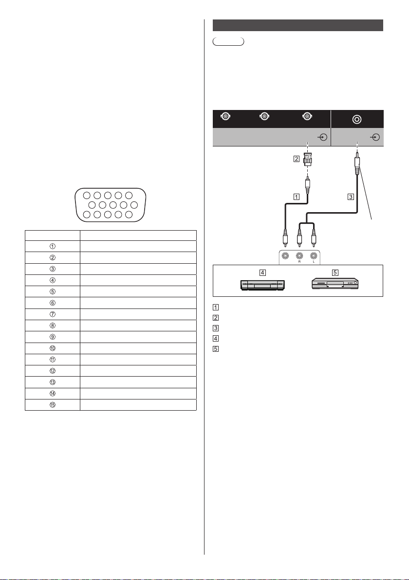
VIDEO IN terminal connection
Note
●
Video equipment, connection cables and conversion
plugs are not supplied with this unit.
●
For audio, it is also possible to use AUDIO1 IN
terminal input. (For [Audio input select] function, see
page 92.)
Shared with COMPONENT/RGB IN.
B/CB
R/PR/CR
COMPONENT/RGB/VIDEO IN
Video pin cable (commercially available)
Pin-BNC conversion plug (commercially available)
Stereo audio cable (commercially available)
Video Cassette Recorder
DVD Player
B/P
G/Y/VIDEO
AUDIO2 IN
Stereo mini plug
(M3)
24
English
Page 25
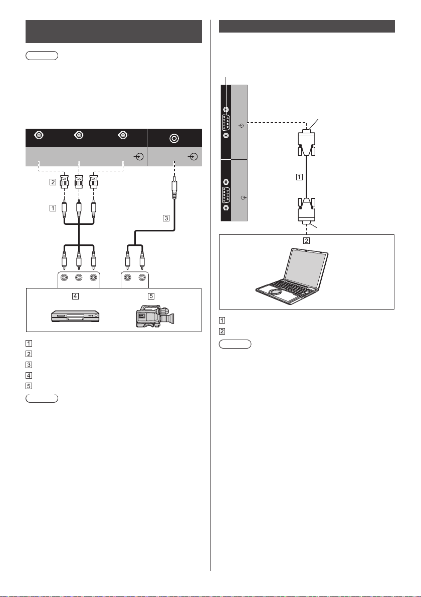
COMPONENT/RGB IN terminal
SERIAL
OUT
SERIAL
IN
connection
Note
●
Video equipment, cables and conversion adapter
shown are not supplied with this unit.
●
For audio, it is also possible to use AUDIO1 IN
terminal input. (For [Audio input select] function, see
page 92.)
SERIAL terminal connection
The SERIAL terminal conforms to the RS-232C interface
specification, so that the Display can be controlled by a
computer which is connected to this terminal.
(Male)
Shared with VIDEO IN.
B/CB
R/PR/CR
COMPONENT/RGB/VIDEO IN
Video pin cable (commercially available)
Pin-BNC conversion plug (commercially available)
Stereo audio cable (commercially available)
DVD Player
RGB camera
Note
●
In accordance with the input signal connected to
COMPONENT/RGB IN terminal, select the input
[Component] or [RGB] in [Signal] - [Component/RGBin select]. (see page 78)
●
The RGB signal input to COMPONENT/RGB IN
terminal corresponds to “SYNC ON G” only.
B/P
G/Y/VIDEO
AUDIO2 IN
Stereo mini
plug (M3)
R LPRPBY
(Female)
D-sub 9p
RS-232C Straight cable (commercially available)
PC
Note
●
Use the RS-232C straight cable to connect the
computer to the Display.
●
Additional computer and cables shown are not
supplied with this set.
English
25
Page 26
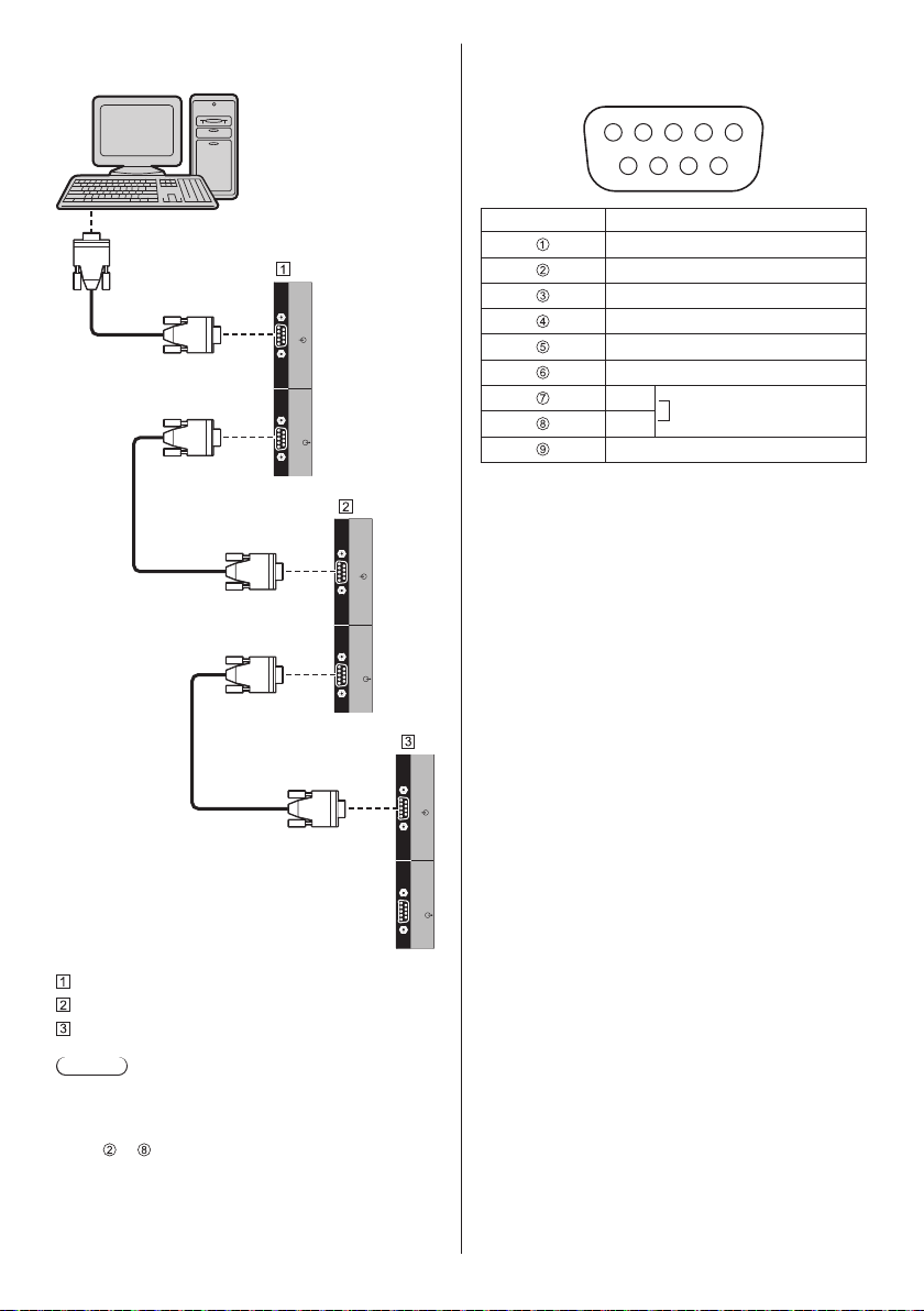
It is possible to daisy chain multiple displays, and
IR IN
SERIAL
OUT
IR OUT
SERIAL
IN
IR IN
SERIAL
OUT
IR OUT
SERIAL
IN
SERIAL
OUT
SERIAL
IN
then control the specific display with PC.
Pin assignments and signal names for SERIAL
Terminal
1 3 4 52
6 7 8 9
Pin No. Signal Name
NC (not connected)
RXD
TXD
Non use
GND (Ground)
Non use
RTS
CTS
Shorted in this set
NC (not connected)
These signal names are those of computer
specifications.
Communication parameters
Signal level: RS-232C compliant
Synchronization method: Asynchronous
Baud rate: 9600 bps
Parity: None
Character length: 8 bits
Stop bit: 1 bit
Flow control: None
First display
Second display
Third display
Note
●
When daisy chaining, set [Options] - [Serial daisy
chain position]. (see page 94)
●
When daisy chaining, use a straight cable which pin
to are hard wired.
No.
English
26
Page 27
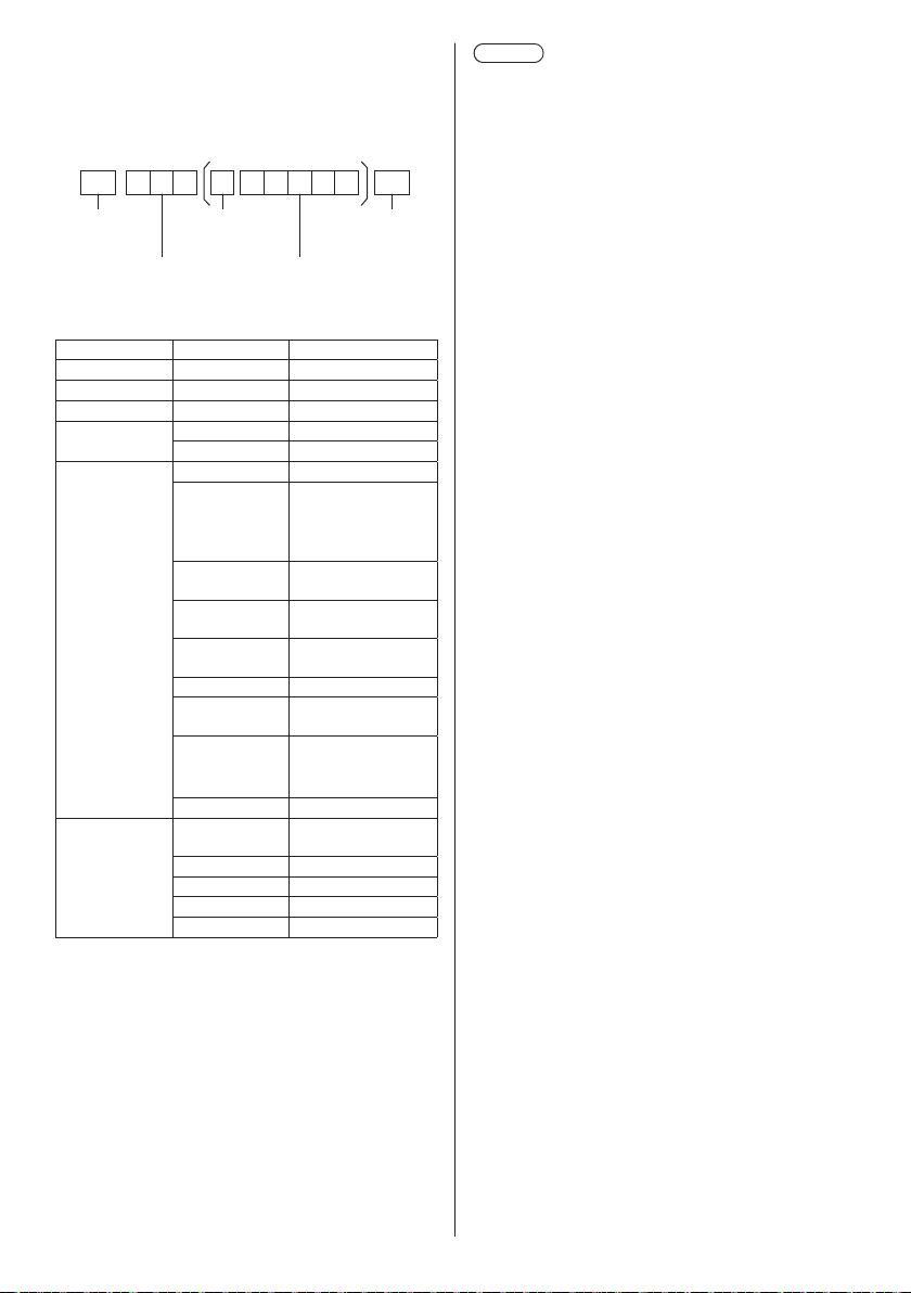
Basic format for control data
The transmission of control data from the computer
starts with a STX signal, followed by the command, the
parameters, and lastly an ETX signal in that order. If
there are no parameters, then the parameter signal does
not need to be sent.
STX C1 C2 C3 P1 P2 P3 P4: P5 ETX
Start
(02h)
3-character command
(3 bytes)
Command
Command Parameter Control details
PON None Power ON
POF None Power OFF
AVL *** Volume 000 - 100
AMT
IMS None Input select (toggle)
DAM
Colon
Parameter(s)
0 Audio MUTE OFF
1 Audio MUTE ON
OpenPort
OP1
HM1
HM2
DV1
PC1 PC IN input (PC)
VD1
YP1
UD1 USB input (USB)
None
ZOOM Zoom1
FULL 16:9
NORM 4:3
ZOM2 Zoom2
PLATFORM input
(OpenPort
PLATFORM)
HDMI 1 input
(HDMI1)
HDMI 2 input
(HDMI2)
DVI-D IN input
(DVI-D)
VIDEO input
(VIDEO)
COMPONENT input
(COMPONENT/
RGB IN)
Screen mode select
(toggle)
End
(03h)
Note
●
If multiple commands are transmitted, be sure to
wait for the response for the first command to come
from this unit before sending the next command.
When sending a command which does not require
parameter, a colon (:) is not needed.
●
If an incorrect command is sent by mistake, this
unit will send an “ER401” command back to the
computer.
●
In Standby condition (power OFF with remote
control), the unit responds to PON command only.
●
Consult your local Panasonic dealer for detail
instructions on command usage.
For more details, visit the following web site.
http://panasonic.net/prodisplays/
English
27
Page 28
IR IN/IR OUT terminal connection
AV IN
USB
Connect the mini plug (M3) cable from the IR OUT
terminal of the first display to the IR IN terminal of the
second display.
The infrared signal of the first display is sent to the
second display.
In this case, the IR (infrared ray reception on the remote
control sensor) on the second display does not operate.
Repeating the above connections enables the daisy
chain connection.
Note
●
Connection cables are not supplied with this unit.
●
Daisy chain connection is possible only between the
displays of the same series.
IR IN
IR OUT
IR IN
IR OUT
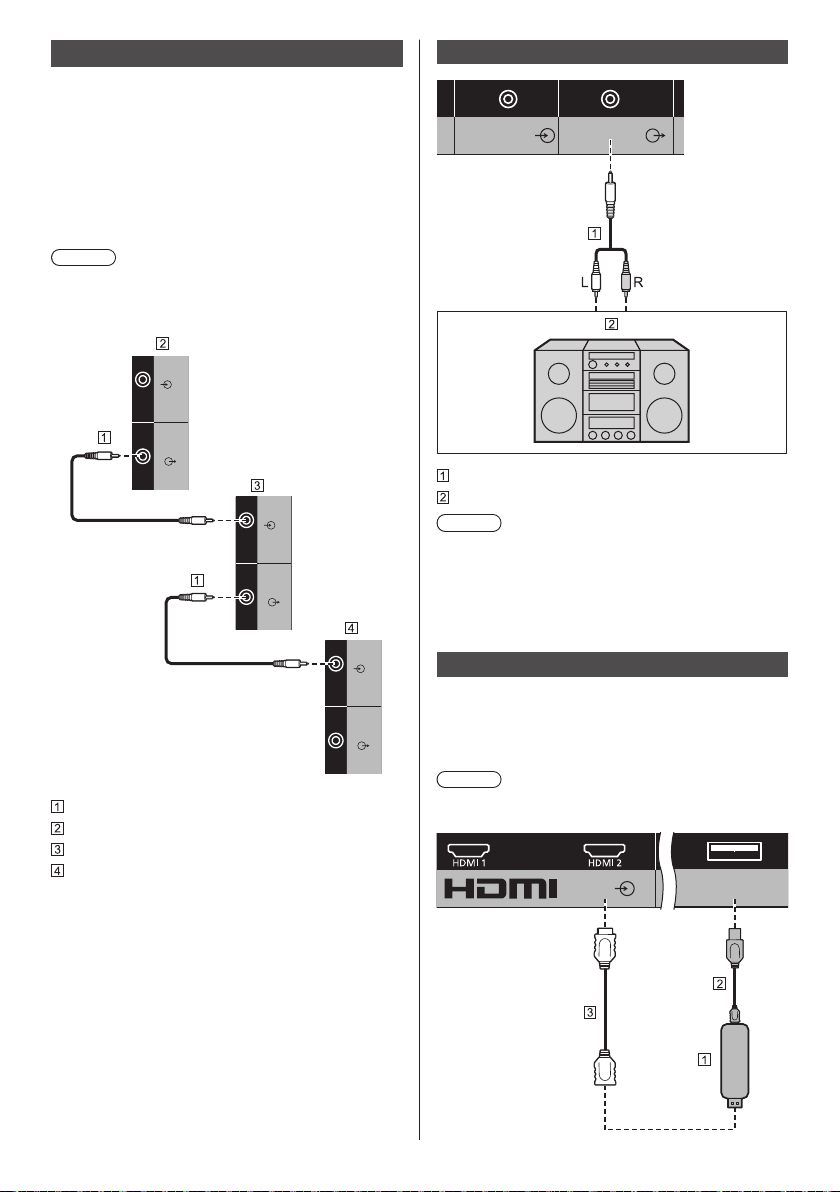
AUDIO OUT terminal connection
AUDIO2 IN AUDIO OUT
Stereo mini plug
(M3)
line-in
Stereo audio cable (commercially available)
Audio equipment
Note
●
Audio equipment and the cable shown are not
supplied with this set.
●
To output sound from AUDIO OUT terminal of the
unit, be sure to set [Output select] in the [Sound]
menu to [AUDIO OUT]. (see page 70)
Stereo mini plug (M3) cable (commercially available)
First display
Second display
Third display
English
28
IR IN
IR OUT
USB terminal connection
Connect the USB memory (commercially available) to
use [USB media player]. (see page 103)
Also, power is supplied when a separately sold stick PC,
etc. are connected.
Note
●
A stick PC and connection cables are not supplied
with this unit.
Page 29
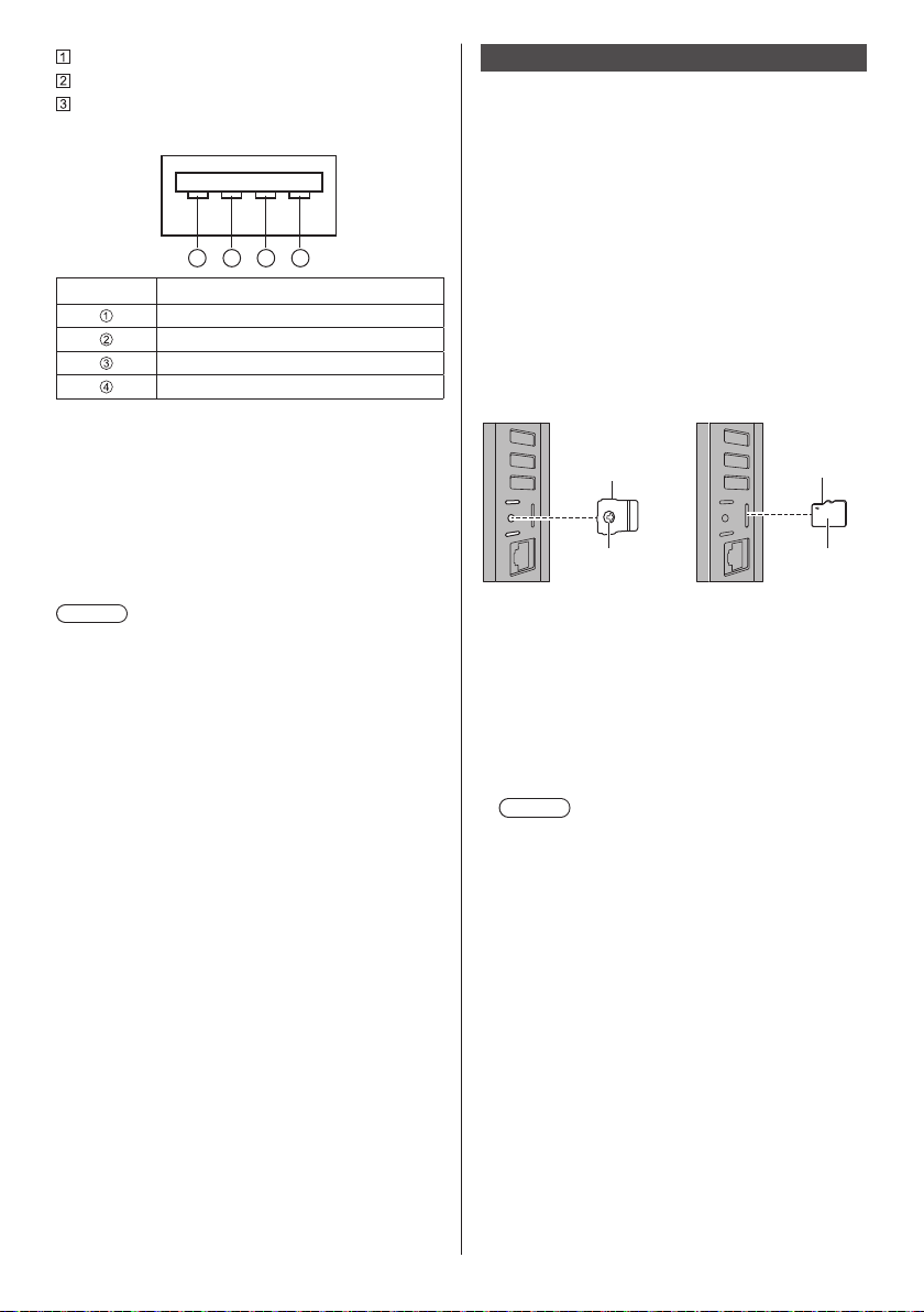
Stick PC
USB cable (commercially available)
HDMI extension cable (commercially available)
Pin assignments and signal names for USB Terminal
1 3 42
Pin No. Signal name
+5 V DC
DATA -
DATA +
GND (Ground)
Power of up to 5V/1A can be supplied to an external
device when the picture is displayed.
●
If the electric current exceeding the power supplying
capability is applied, the output is blocked, and the
following message is displayed.
[USB DC5V OUT overload. Please remove cable or
equipment, then turn the display off/on.]
In this case, remove the equipment and then turn the
power off/on using the remote control, etc.
Note
●
If the direct connection to this unit is not possible due
to the size of a stick PC, etc. use a commercially sold
extension cable.
●
Depending on the type of a USB memory device,
it may come in contact with the periphery such
as a back cover, and cannot be attached. Use a
commercially sold extension cable, or use a small
type of a USB memory device connectable to this
unit.
●
Depending on the USB memory, the access lamp
may remain blinking even when it is not being
accessed. In this case, remove the device after
switching to the input other than USB.
Also, when data cloning is running, remove the device
after the screen to notify it is finished is displayed.
(see page 107)
Using microSD card
By attaching a microSD card (commercially available)
to the microSD card slot, use it as external storage for
OpenPort PLATFORM system.
(see page 47)
■ microSD card usable on this unit
The following microSD card compliant with SD standard
can be used on this unit.
(Such cards are referred to as microSD card in this
manual.)
microSD memory card (64 MB to 2 GB)
•
microSDHC memory card (4 GB to 32 GB)
•
Only the Fat16-formatted microSD card and FAT32formatted microSD card can be used on this unit.
■ To insert or remove the microSD card
microSD card
cover
Screw
1 Using a driver, loosen the screw of the microSD
card cover (anti-theft cover), and remove the
cover.
2 Make the surface of the microSD card face back
side of the unit, and insert it securely until a
clicking sound is heard.
●
For removal, push in the card until it clicks, and pull
it out straight.
3 Attach the cover to the original position.
Note
●
Do not touch the connection terminal of the
microSD card.
●
Before attaching or removing the microSD card
cover, turn the unit off with <Main Power On / Off
button>.
●
Be careful not to lose the removed cover. Be sure
to attach it to the original position.
●
While the microSD card is operating, do not turn
this unit off, pull out the microSD card, or subject
this unit to vibration, shock or static electricity.
Saved data, etc. may be lost, or malfunction may
occur.
●
When removing a microSD card, unmount the SD
card. (see page 57)
●
Do not insert non-standard microSD cards, or
cards other than the microSD card.
Malfunction may occur.
microSD card
Surface
English
29
Page 30
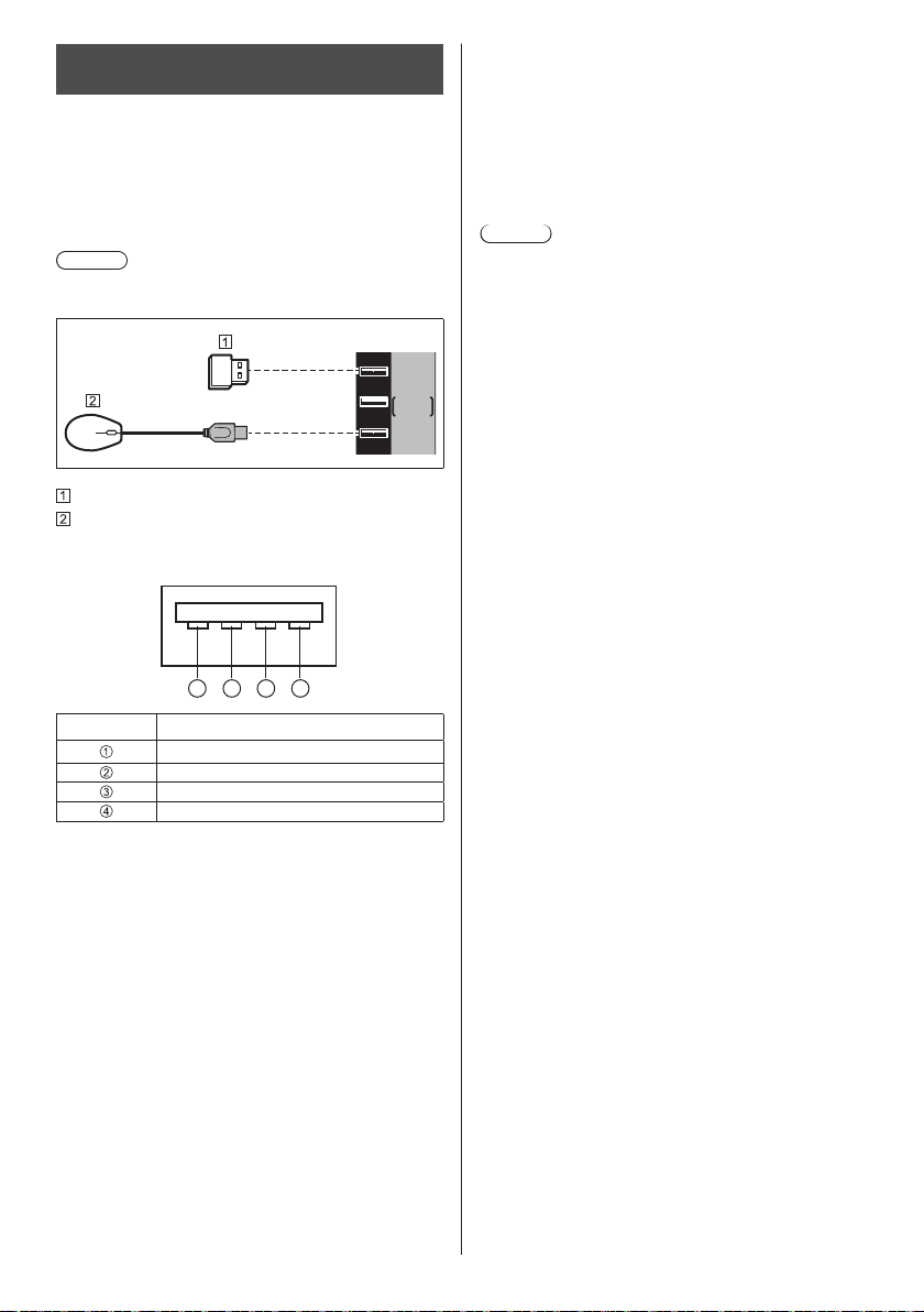
USB (OpenPort PLATFORM) terminal
1 3 42
connection
By attaching a USB memory (commercially available)
to the USB (OpenPort PLATFORM) terminal, use it as
external storage for OpenPort PLATFORM system. (see
page 47)
With OpenPort PLATFORM input, it is possible to
connect and use USB devices such as a USB mouse, a
USB keyboard, etc. (see page 43, 44)
Note
●
USB memory, USB device and cable shown are not
supplied with this unit.
USB
OpenPort
PLATFORM
USB memory
USB mouse (commercially available)
Pin assignments and signal names for USB
(OpenPort PLATFORM) Terminal
■ About compatible USB memory
●
Commercially available USB memory devices are
compatible. (The ones with security function are not
compatible.)
●
Only the Fat16-formatted ones and FAT32-formatted
ones can be used on this unit.
●
The maximum memory size of USB is 32 GB.
●
Only a single partition configuration is supported.
Note
●
When removing a USB memory, unmount the USB
memory. (see page 57)
●
Depending on the type of a USB memory device,
it may come in contact with the periphery such
as a back cover, and cannot be attached. Use a
commercially sold extension cable, or use a small
type of a USB memory device connectable to this
unit.
●
If the direct connection to this unit is not possible due
to the size of the USB device, use a commercially
sold extension cable.
Pin No. Signal Name
+5 V DC
DATA
DATA
GND (Ground)
Each USB (OpenPort PLATFORM) terminal is capable
of supplying power of up to 5V/500mA to an external
device when the picture is displayed or it is in standby
condition (Power Indicator: Orange) (see page 32).
●
If the electric current exceeding the power supplying
capability is applied, the output is blocked, and the
following message is displayed on the screen.
(In standby condition, the message is displayed when
the picture is displayed next time.)
[USB DC5V OUT overload (OpenPort PLATFORM).
Please remove cable or equipment, then turn the
display off/on.]
In this case, remove the connected equipment, and
then turn the power off/on with the <Main Power On /
Off button>.
English
30
Page 31

Micro-USB terminal connection
By connecting the unit to the PC using the Micro-USB
cable, data in the storage of the OpenPort PLATFORM
system can be read or written from the PC.
Micro-USB
Micro-USB cable (commercially available)
PC
Pin assignments and signal names for Micro-USB
Terminal
345 2 1
Pin No. Signal Name
+5 V DC
DATA
DATA
ID
GND (Ground)
The Micro-USB terminal is capable of supplying power
of up to 5V/500mA to an external device when the
picture is displayed or it is in standby condition (Power
Indicator: Orange) (see page 32).
●
If the electric current exceeding the power supplying
capability is applied, the output is blocked, and the
following message is displayed on the screen.
(In standby condition, the message is displayed when
the picture is displayed next time.)
[USB DC5V OUT overload (OpenPort PLATFORM).
Please remove cable or equipment, then turn the
display off/on.]
In this case, remove the connected equipment, and
then turn the power off/on with the <Main Power On /
Off button>.
Note
●
Additional computer and cables shown are not
supplied with this set.
●
Insert or remove the Micro-USB cable slow and
straight, avoiding excessive force.
English
31
Page 32
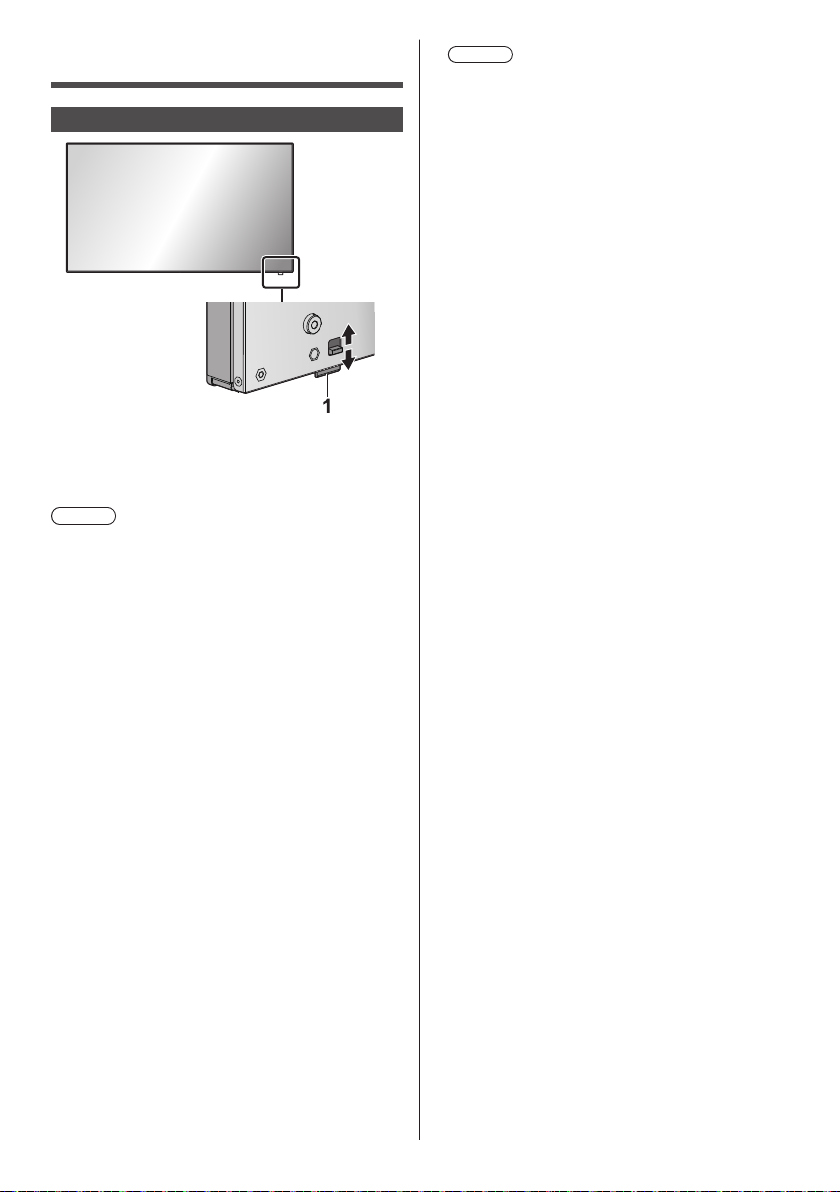
Identifying Controls
Main unit
●
To take out/store the power indicator and remote
control sensor, operate the lever on the rear panel.
It is also possible to press the remote control
sensor directly to store.
Note
●
For normal use, pull out the power indicator and
remote control sensor from the edge side of the
main unit by operating the lever on the rear panel.
Depending on the setup condition such as when
using the multi display, store them in the main unit.
1 Power Indicator / Remote control sensor
The Power Indicator will light.
When the power of the unit is ON (Main Power On
/ Off button: ON)
●
Picture is displayed: Green
●
Power OFF (standby) with remote control:
When [OpenPort PLATFORM standby] is set to
•
[Off]: Red
When [OpenPort PLATFORM standby] is set to
•
[On]: Orange (Red/Green)
About [OpenPort PLATFORM standby] settings,
see page 83.
●
Power OFF (sleep) with “Power management”
function: Orange (Red/Green)
About “Power management” function, see page 81.
When the power of the unit is OFF (Main Power
On / Off button: OFF): No light
Note
●
Even if the display unit is turned off with the power
indicator off, some of the circuits are in power-on
status.
●
When the power indicator is orange, power
consumption during standby/sleep is generally
larger than that of when the power indicator is red.
●
When the power indicator is changing from green
showing the picture is displayed to red or off, while
the OpenPort PLATFORM system is shutting down,
the indicator temporarily illuminates in orange. In
this status, the remote control operation is ignored.
●
When the <Main Power On / Off button> is pressed
while the power indicator is lighting in orange
(standby or sleep status), the power indicator blinks
once, and then the shutdown processing of the
OpenPort PLATFORM system (see page 40) is
performed.
When the shutdown is complete, the power
indicator goes off.
32
English
Page 33

Unit
INPUT
MENU
ENTER
1 External Input Terminal
Connects to video equipment, PC, etc. (see page 19)
2 <Main Power On / Off button>
Turns the power On / Off.
3 <INPUT (Unit)>
Selects the connected device. (see page 37)
●
In OpenPort PLATFORM operation mode
[EXIT]: Exits OpenPort PLATFORM operation
mode and returns to the operation of the
inputs other than OpenPort PLATFORM.
(see page 42)
4 <MENU (Unit)>
Displays the menu screen. (see page 66)
●
With OpenPort PLATFORM input
Switches to OpenPort PLATFORM operation
mode. (see page 42)
●
In OpenPort PLATFORM operation mode
[BACK]: Returns to the previous screen.
[HOME]: Press and hold to display the home
screen. (see page 42)
5 <+ (Unit)> / <- (Unit)>
Adjusts the volume. (see page 38)
On the main screen, switches settings or adjusts
settings level. (see page 66)
●
In OpenPort PLATFORM operation mode
[RIGHT], [LEFT]:
Moves the cursor from side to side.
[KEYBOARD]:
Press and hold <- (Unit)> to display the software
keyboard. (see page 42)
55-inch model
49-inch model
42-inch model
8
8
8
(Unit)> / < (Unit)>
6 <
Selects the setting item on menu screen. (see page
66)
●
In OpenPort PLATFORM operation mode
[UP], [DOWN]:
Moves the cursor up and down. (see page 42)
7 <ENTER (Unit)>
Configures the item on menu screen. (see page 66)
Switches aspect mode. (see page 64)
●
In OpenPort PLATFORM operation mode
[ENTER]:
Configures the item.
[LONG PRESS ENTER]:
Used for the operation that requires long press.
(see page 42)
8 Built-in speakers
●
To output sound from the built-in speakers of the
unit, be sure to set [Output select] in the [Sound]
menu to [SPEAKERS]. (see page 70)
Note
●
For more details on button operation of OpenPort
PLATFORM, see page 42.
English
33
Page 34
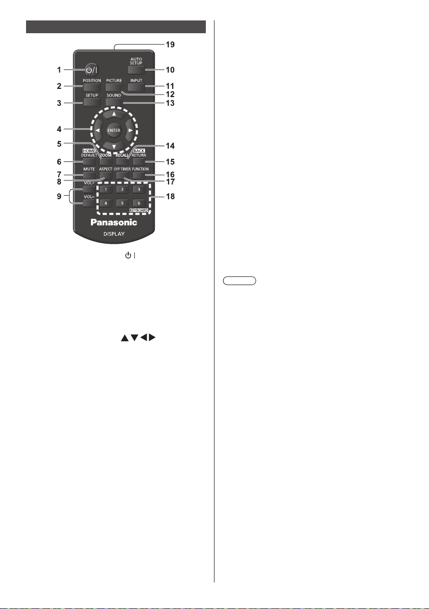
Remote Control Transmitter
1 Standby (ON/OFF) button ( / )
●
Turns the power on or off when the Display is
turned on at the <Main Power On / Off button>.
(see page 35)
2 POSITION
(see page 68)
3 SETUP
(see page 78)
4 ENTER / Cursor buttons (
●
Used to operate the menu screens. (see page 66)
●
With OpenPort PLATFORM input
Confirms the selected item, or move the cursor
from right to left or up and down. (see page 41)
5 ZOOM
Enters the digital zoom mode. (see page 65)
6 DEFAULT/HOME
●
Resets the settings of picture, sound, etc., to
defaults. (see page 68, 70, 71)
●
With OpenPort PLATFORM input
Displays the home screen. (see page 41)
7 MUTE
●
Sound mute on / off. (see page 38)
8 ASPECT
●
Adjusts the aspect. (see page 64)
9 VOL + / VOL -
●
Adjusts sound volume level. (see page 38)
10 AUTO SETUP
●
Automatically adjusts the position/size of the
screen. (see page 68)
11 INPUT
●
Switches input to display on the screen. (see page
37)
English
34
)
12 PICTURE
(see page 71)
13 SOUND
(see page 70)
14 RECALL
●
Displays the current setting status of Input mode,
Aspect mode, etc. (see page 38)
15 RETURN/BACK
●
Used to return to the previous menu. (see page 66)
●
With OpenPort PLATFORM input
Returns to the previous screen. (see page 41)
16 FUNCTION
●
Displays [Function button guide].
(see page 86)
17 OFF TIMER
●
Switches to stand-by after a fixed period. (see
page 39)
18 Numeric buttons (1 - 6) / KEYBOARD
●
Used as shortcut buttons by assigning frequently
used operations. (see page 86)
●
With OpenPort PLATFORM input
Press <KEYBOARD> to display the software
keyboard. (see page 41)
19 Signal emission
Note
●
In this manual, buttons of the remote control and the
unit are indicated as < >.
(Example: <INPUT>.)
The operation is mainly explained indicating the
remote control buttons but you can also operate with
the buttons on the unit when there are the same
buttons.
Page 35

Basic Controls
AC socket outlet
AC cord (supplied)
Main Power On / Off button
(Back of the unit)
Operate pointing the remote control directly at
the unit’s Remote Control Sensor.
Note
●
For normal use, pull out the remote control sensor
from the edge side of the main unit by operating the
lever on the rear panel. (see page 32)
●
Do not put an obstacle between the remote control
sensor of the main unit and the remote control.
●
Operate the remote control in front of the remote
control sensor or from the area where the sensor can
be seen.
●
When directly aiming the remote control at the remote
control sensor of the main unit, the distance from
the front of remote control sensor should be approx.
7 m or less. Depending on the angle, the operation
distance may be shorter.
●
Do not subject the remote control sensor of the main
unit to the direct sunlight or strong fluorescent light.
Remote Control Sensor /
Power Indicator
Connect the AC cord plug to the
1
Display.
(see page 18)
Connect the plug to the socket outlet.
2
Note
●
Main plug types vary between countries. The
power plug shown at left may, therefore, not be the
type fitted to your set.
●
When disconnecting the AC cord, be absolutely
sure to disconnect the AC cord plug at the socket
outlet first.
●
The settings may not be saved if the power plug is
disconnected immediately after changing settings
with on-screen menu. Disconnect the power plug
after a enough period of time. Or, disconnect the
power plug after turning the power off with the
remote control, RS-232C control or LAN control.
Press the <Main Power On / Off
3
button> on the unit to turn the set on:
Power-On.
●
Power Indicator: Green (Picture is displayed.)
●
When the power of the unit is ON, remote control
operation is possible.
■ To turn the power ON/OFF with the remote
control
Press the <Standby (ON/OFF) button> to turn the
Display on.
Power Indicator: Green (Picture is displayed.)
•
Press the <Standby (ON/OFF) button> to turn the
Display off.
When [OpenPort PLATFORM standby] is set to [Off]
Power Indicator: Red (standby)
•
When [OpenPort PLATFORM standby] is set to [On]
Power Indicator: Orange (Red/Green) (standby)
•
(About [OpenPort PLATFORM standby] settings, see
page 83.)
■ To turn the power OFF with the <Main
Power On / Off button>
●
When the power of the unit is ON (Picture is
displayed: Power indicator in green):
Pressing the <Main Power On / Off button> will
illuminate the power indicator in orange. When it goes
off, the display unit turns off.
While the indicator is illuminating in orange, the
remote control operation is ignored.
English
35
Page 36
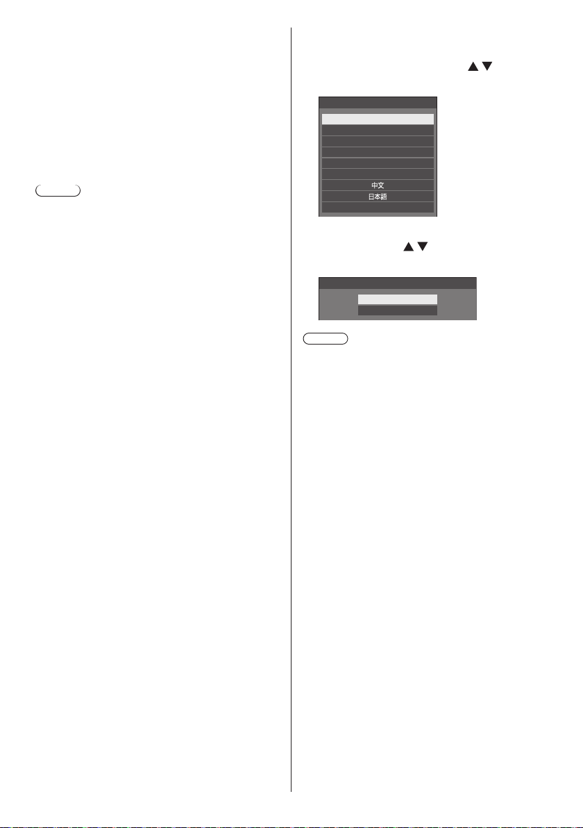
●
When the power of the unit is ON (Standby/Sleep:
Power indicator in orange):
Pressing the <Main Power On / Off button> will
turn the power indicator off for a moment, and then
illuminate it in orange. When it goes off, the display
unit turns off.
While the indicator is illuminating in orange, the
remote control operation is ignored.
●
When the power of the unit is ON (Standby: Power
indicator in red):
Pressing the <Main Power On / Off button> will turn
the power indicator off and the display unit turns off.
Note
●
During operation of the “Power management” function
(see page 81), the power indicator turns orange in the
power off (sleep) state.
■ When the Unit is turned on for the first time
Following screen will be displayed.
Select the language with and
1
press <ENTER>.
OSD language
English (UK)
Deutsch
Français
Italiano
Español
ENGLISH (US)
Русский
For vertical installation, select
2
[Portrait] with and press
<ENTER>.
Display orientation
Landscape
Portrait
Note
●
Once the items are set, the screens won’t be
displayed when switching on the unit next time.
After the setting, the items can be changed in the
following menus.
[OSD language] (see page 83)
[Display orientation] (see page 87)
●
When [Display orientation] is set to [Portrait],
a confirmation message to restart OpenPort
PLATFORM is displayed.
36
English
Page 37
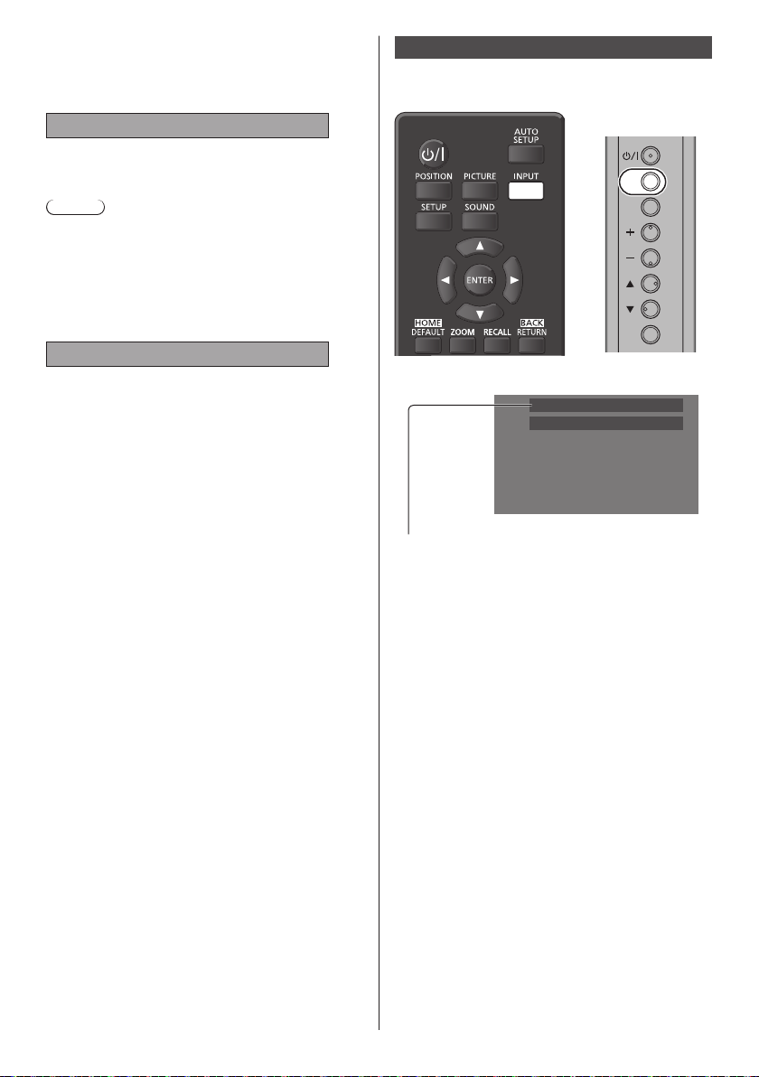
■ Power ON message
The following message may be displayed when turning
the unit power ON:
No activity power off Precautions
‘No activity power off’ is enabled.
When [No activity power off] in the [Setup] menu is set to
[Enable], a warning message is displayed every time the
power is turned ON. (see page 83)
Note
●
[No activity power off] is not activated with OpenPort
PLATFORM input. The message [ ‘No activity power
off’ is enabled.] is not displayed, either.
●
The message [Last turn off due to ‘No activity power
off’.] is also displayed when OpenPort PLATFORM
input is used at the time the display is turned on.
“Power management” Information
Last turn off due to ‘Power management’.
When “Power management” is functioned, an
information message is displayed every time the power
is turned ON. (see page 81)
These message displays can be set with the following
menu:
●
[Options] menu
Power on message(No activity power off)
(see page 96)
Power on message(Power management)
(see page 96)
Selecting the input signal
Select the signals input to the unit.
Press <INPUT> or <INPUT (Unit)>.
Unit
INPUT
MENU
ENTER
Switches input every time the buttons are pressed.
PC
16:9
[OpenPort PLATFORM] → [HDMI1] → [HDMI2] →
[DVI-D] → [PC] → [COMPONENT]* → [VIDEO] →
[USB]
[OpenPort PLATFORM]:
OpenPort PLATFORM system built into this unit.
[HDMI1]:
HDMI 1 terminal, HDMI input
[HDMI2]:
HDMI 2 terminal, HDMI input
[DVI-D]:
DVI-D IN terminal, DVI-D input
[PC]:
PC IN terminal, PC input
[COMPONENT]*:
COMPONENT/RGB IN terminal, Component input
[VIDEO]:
VIDEO terminal, composite video input
[USB]:
USB terminal, USB input
: [COMPONENT] may be displayed as [RGB]
*
depending on the settings of [Component/RGB-in
select]. (see page 78)
English
37
Page 38

Note
●
Displays the signal name as set in [Input label]. (see
page 81)
●
Input will not be switched unless [Input lock] is set to
[Off]. (see page 93)
●
Image retention (image lag) may occur on the LCD
display panel when a still picture is kept on the panel
for an extended period. To prevent such a problem,
using the screensaver and wobbling is recommended.
(see page 80, 83)
RECALL
It is possible to check the setting status of input label,
picture mode, etc.
Press <RECALL>.
Volume Adjustment
Press <VOL +> <VOL -> or <+ (Unit)> <- (Unit)> to
adjust volume.
Unit
INPUT
MENU
ENTER
Current setting status will be displayed.
PC
16:9
Backup mode OK
AUDIO1 IN
Memory name: MEMORY 2
10:00
Off timer
90 min
1 Input label
2 Aspect mode (see page 64)
3 Backup input change (see page 90)
4 Audio input (see page 92)
5 Profile name (see page 75)
6 Off timer remaining time (see page 39)
7 Clock / Mute (see page 38, 59)
●
The followings are displayed for about 30 seconds at
the end: [No signal] - when there is no video signal to
the selected input, [No external media] - when a USB
memory is not connected to the USB terminal at the
time of using the USB input.
During the OpenPort PLATFORM input, “no signal” is
not discriminated.
●
To display the clock, set [Date & time] in OpenPort
PLATFORM, and then set [Clock display] to [On].
(see page 59, 95)
Volume (SPEAKERS)
●
The current sound volume level is memorised even if
20
the power is turned off.
●
When [Maximum VOL level] is set to [On], the volume
can only be adjusted to the maximum point you set,
and the displayed value turns red when it reached its
maximum. (see page 93)
●
When [Initial VOL level] is set to [On], the volume will
1
2
3
4
5
be at the set level when the display is turned on. (see
page 92)
Sound mute On / Off
It is useful when you want to mute the sound temporarily,
for example, when answering the phone or door.
6
Press <MUTE>.
●
7
appears on the screen and the sound is muted.
Press again to reactivate the sound.
●
It is also reactivated when the power is turned on / off
or the volume level is changed.
●
While MUTE is active,
is displayed as a reminder
after operation.
●
In [ENGLISH(US)] OSD language,
[MUTE].
is displayed as
38
English
Page 39

OFF TIMER
The Display can be preset to switch to stand-by after a
fixed period. (30 min, 60 min, 90 min)
The setting switches each time <OFF TIMER> is
pressed.
●
[0 min]→[30 min]→[60 min]→[90 min]
→[0 min] (Cancel)
●
When three minutes remain, the remaining time will
flash (Red). After that, it switches to stand-by.
●
To see the Off timer remaining time, press
<RECALL>.
The Off timer is cancelled if a power interruption occurs.
When the power is turned on later on, it will be in standby condition.
English
39
Page 40

Startup of OpenPort PLATFORM
This unit is equipped with the OpenPort PLATFORM system based on Android.
Set the input select to OpenPort PLATFORM for using. (see page 37)
Startup
The startup processing of the OpenPort PLATFORM system is performed when the unit starts up while the power
indicator is off (power-off status) or lighting in red (standby status).
The startup screen appears while the unit is starting up in the OpenPort PLATFORM input selection status.
Note
●
Approx. 40 seconds for startup. When starting up for the first time, approx. 70 seconds are taken.
●
When [Options] - [Startup logo] is set to [On], this is displayed followed by the Panasonic logo. (see page 94)
●
When the power indicator is lighting in orange (standby or sleep status), the OpenPort PLATFORM system is
operating. When the unit starts up in this status, the startup screen does not appear.
●
When OpenPort PLATFORM cannot respond for some reason, it is restarted automatically and then the recovery
processing is performed.
Shutdown
The shutdown processing of the OpenPort PLATFORM system is performed either when the power is turned off using
the <Main Power On / Off button> or the power is turned off using the remote control, etc. when [Setup] - [OpenPort
PLATFORM standby] is set to [Off] (see page 83).
During shutdown process, the power indicator lights up in orange from green illumination, the message [Shutting down
OpenPort PLATFORM. Please wait.] appears.
Note
●
Approx. 30 seconds for shutdown.
●
While the OpenPort PLATFORM system is shutting down, the remote control operation or external control
commands are not accepted.
●
When the unit is in standby status (Power Indicator: Red) by shutting down the OpenPort PLATFORM system, the
wired LAN or wireless LAN networks are cut, and the power can be turned on only by the following operations. (The
power cannot be turned on by [Setup] - [Set up timer] as well. (see page 85))
Power-on by the power button of remote control
•
“PON” command reception from the SERIAL terminal
•
Forcibly shutting down the OpenPort PLATFORM system
[TOOLS] - [Shutdown] (see page 61)
[OpenPort PLATFORM Shutdown] (see page 112)
40
Page 41

Basic Operation/Character Input for OpenPort PLATFORM
Remote Control Transmitter
The following remote control buttons are designed for the OpenPort PLATFORM operation.
1 <ENTER> / Cursor buttons
●
Confirms the selected item, or move the cursor (focus) from right to left or up and down.
Icons or items may be focused only after operating the buttons.
*
2 <HOME>
●
Displays the home screen.
3 <BACK>
●
Returns to the previous screen.
4 <KEYBOARD>
●
Shows or hides the software keyboard.
Note
●
For button operations other than OpenPort PLATFORM operation, see page 34.
●
The remote control operation designed for the OpenPort PLATFORM operation is not available while the on-screen
display is displayed. Operate after hiding the on-screen display, or after it is disappeared.
●
Some applications cannot be operated using the remote control. In this case, use a USB mouse (commercially
available) for operation. (see page 43)
41
Page 42
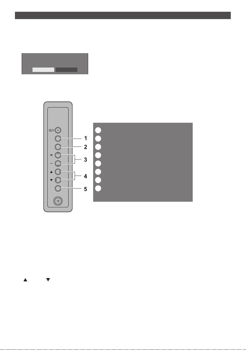
Buttons on the main unit
■ OpenPort PLATFORM operation mode
Using the main unit buttons instead of the remote control can operate OpenPort PLATFORM.
When using the OpenPort PLATFORM input, press <MENU (Unit)>.
1
The following screen appears.
Do you want to control OpenPort PLATFORM?
Yes No
Select [Yes] with <+ (Unit)> <- (Unit)> and press <ENTER>.
2
Enters the OpenPort PLATFORM operation mode. The operation guide of the main unit button is displayed.
The operation guide disappears by exiting the OpenPort PLATFORM operation mode.
POWER
INPUT
MENU
ENTER
EXIT
BACK/HOME(*)
RIGHT
LEFT/KEYBOARD(*)
UP
DOWN
ENTER/LONG PRESS ENTER(*)
(*) Long press
1 <INPUT (Unit)>
[EXIT]: Exits OpenPort PLATFORM operation mode and returns to the operation of the inputs other than OpenPort
PLATFORM.
2 <MENU (Unit)>
[BACK]: Returns to the previous screen.
[HOME(
)]: Press and hold to display the home screen.
3 <+ (Unit)> <- (Unit)>
4 <
5 <ENTER (Unit)>
*
[RIGHT], [LEFT]: Moves the cursor (focus) from side to side.
[KEYBOARD(
<- (Unit)> to hide.
(Unit)> < (Unit)>
[UP], [DOWN]: Moves the cursor (focus) up and down.
[ENTER]: Configures the item.
[LONG PRESS ENTER(
The (*) mark for operation guides shows the long press operation.
*
)]: Press and hold <- (Unit)> to display the software keyboard. While it is displayed, press and hold
*
)]: Used for the operation that requires long press.
*
42
Page 43

USB mouse
?123
=\<
ABC
A USB mouse (commercially available) can perform the OpenPort PLATFORM operation.
●
Connect the USB mouse to the USB (OpenPort PLATFORM) terminal.
●
The USB mouse can perform the swipe or drag operation that cannot be performed using the remote control.
●
Some applications cannot be operated using the remote control. In this case, use a USB mouse.
●
When an optical mouse is used, its movement may not be reflected properly, depending on the accuracy of reading.
Software keyboard
Use the software keyboard when inputting characters for OpenPort PLATFORM.
For displaying or hiding the software keyboard: see page 41, 42
■ [OpenPort keyboard]
This is the OpenPort PLATFORM-unique software keyboard.
Example: Alphabet input (lowercase character)
Example: Number and symbol input
Example: Mathematical symbol and currency symbol input
●
Compatible with the input of alphanumeric characters and symbols.
●
Candidates for words are not displayed.
●
Use the cursor button or <ENTER> button of the remote control for operation.
A USB mouse (commercially available) can also be used.
●
The selected key is enlarged for display.
●
The input position can be moved from side to side with
Switching the input characters
.
Switches between the uppercase and the lowercase of alphabet input.
Switches to the number and symbol input from the alphabet input or from the mathematical symbol
and currency symbol input.
Switches to the mathematical symbol and currency symbol input from the number and symbol input.
Switches to the alphabet input from the number and symbol input or from the mathematical symbol
and currency symbol input.
43
Page 44

Changing the software keyboard
The software keyboard can be changed from [OpenPort keyboard] to [Android Keyboard (AOSP)] in [SETUP] (or
[TOOLS] - [Settings]) - [Language & input]. (see page 58)
■ [Android Keyboard (AOSP)]
This is the Android standard software keyboard.
Example: Alphabet input
●
Compatible with the multi-lingual input.
●
Candidates for words are displayed. (May not be displayed with some applications.)
●
The remote control operation is not possible. Use a USB mouse for operation.
●
Depending on the application, a keyboard designed for inputting numbers may be displayed.
USB keyboard
A USB keyboard (commercially available) instead of software keyboard can be used for the character input of
OpenPort PLATFORM.
●
Connect the USB keyboard to the USB (OpenPort PLATFORM) terminal.
●
Depending on the keyboard, some key operations are invalid.
●
Setting the keyboard layout (for each language): [SETUP] (or [TOOLS] - [Settings]) - [Language & input] (see page
58)
Operation icon
When operating (such as clicking on the screen) with a USB mouse (commercially available), the following operation
icons are displayed.
BACK HOME RECENT APPS
Click the USB mouse for operation. These operation icons cannot be selected or operated using the remote control.
[BACK]: Returns to the previous screen. (Same operation as with the <BACK> button of the remote control)
[HOME]: Displays the home screen. (Same operation as with the <HOME> button of the remote control)
[RECENT APPS]: Displays the screen (Android standard screen) of the application recently used. (see page 63)
Note
●
When the operation icons are not displayed, they will be displayed by swiping the screen from the bottom edge to
the top with a mouse.
44
Page 45

Home Screen of OpenPort PLATFORM
When OpenPort PLATFORM starts up, the home screen is displayed at first.
6 button icons are displayed on the home screen.
Select the icon with cursor buttons on the remote control and press <ENTER>.
Moves to the screen of the selected icon.
[SETUP]: Set [WIRELESS & NETWORKS], [Language & input] and [Date & time settings]. (see page 46)
[INSTALLER]: Use this when installing a new application. (see page 47)
[TOOLS]: Pre-installed applications for various setups are collected here. Each application can be started up
[FAVORITE]: Register your favourite applications and start them up from here. (see page 49)
[RECENTS]: Recently used applications are displayed. Each application can be started up from here.
[STATUS]: The model information of this unit and network-related setting information can be confirmed. (see
from here. (see page 49)
(see page 51)
page 52)
Note
●
As factory default, the home screen is set to this unit unique [QuickLauncher] screen. It is also possible to switch to
the Android standard, [Launcher] screen. (see page 57)
●
It is recommended selecting [QuickLauncher] for this unit.
●
In this manual, explanations are mainly based on the case where [QuickLauncher] is selected.
●
If an application such as signage player starting up automatically has been set at the startup of OpenPort
PLATFORM, the screen of the application is displayed. (see page 60)
45
Page 46

[SETUP] screen of OpenPort PLATFORM
Select the [SETUP] button icon on the home screen to display the [SETUP] application screen.
Set [WIRELESS & NETWORKS], [Language & input] and [Date & time settings].
Select the item with and press <ENTER>.
Switches to the setting screen of the selected item.
Returns to the [SETUP] screen with <BACK>.
[WIRELESS &
NETWORKS]:
[Language & input]: Sets the language to use, input method, etc.
[Date & time settings]: Sets the date and time.
Note
●
If connected to the network, the date and time can be automatically set. However, it will be required to set the time
zone. Set manually. (see page 59)
●
If not connected to the network, set the date and time manually. (Use a USB mouse for setting.)
●
If the clock shows wrong time soon after set to the right time, replace the battery inside the unit. Consult the dealer
where you purchased the product.
●
In the network condition where both the wired LAN and wireless LAN operate, the wired LAN is prioritized for
operation. When using the wireless LAN, disconnect the wired LAN cable.
Make various settings for network.
It is also possible to set in [TOOLS] - [Settings] - [WIRELESS & NETWORKS]. (see page 55)
Make this setting before using the network.
It is also possible to set in [TOOLS] - [Settings] - [Language & input]. (see page 58)
It is also possible to set in [TOOLS] - [Settings] - [Date & time]. (see page 59)
46
Page 47

[INSTALLER] screen of OpenPort PLATFORM
Select the [INSTALLER] button icon on the home screen to display the [INSTALLER] application screen.
Use this when installing a new application.
■ Installing the application from the external storage (microSD card, USB memory (USB
(OpenPort PLATFORM) terminal))
Searches the external storage for the installation file of the application, and displays it on the list.
Select the installation file from the displayed list, and press <ENTER>.
Starts to install the application.
Depending on the application, the message [Install blocked] appears, and the installation may not be performed.
In this case, the installation is possible by [All installation of apps from unknown sources]. Add a check mark for
[Unknown sources].
[TOOLS] - [Settings] - [Security] (see page 58)
●
When the application list is not displayed, select the [Search Again] button and press <ENTER>.
47
Page 48

■ Installing the application from the application server
Select [App Server] and press <ENTER>.
1
Connects to the application server, and displays the application list screen.
Select the application to download and press <ENTER>.
2
It is possible to search and refine applications in accordance with the model number (the model number of this unit
is set automatically), category and application name.
Automatically starts to install the application after downloading is complete. Follow the displayed instructions to
perform the installation.
Note
●
Design of the download screen is subject to change.
48
Page 49
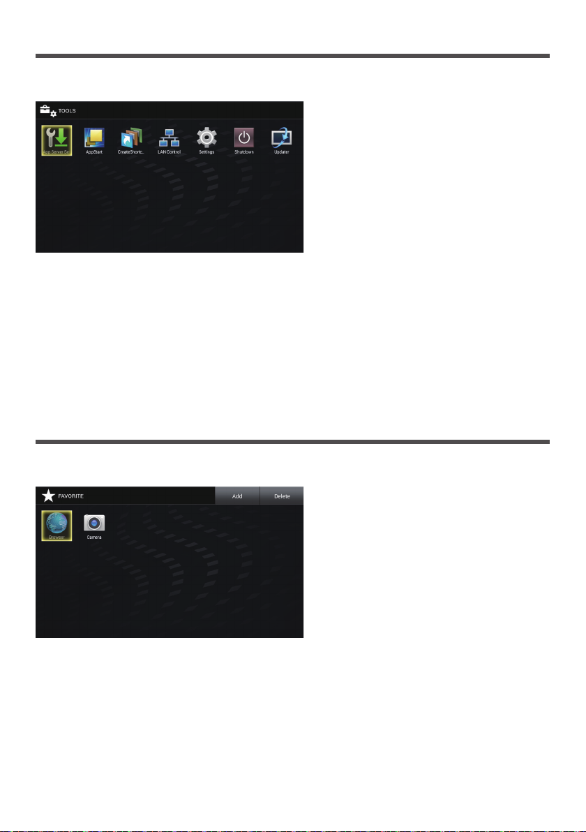
[TOOLS] screen of OpenPort PLATFORM
Select the [TOOLS] button icon on the home screen to display the [TOOLS] screen.
Various setting-related applications pre-installed are collectively displayed with icons.
Select the application to start up, and press <ENTER>.
The application starts up. For details of each application, see the following pages.
[App Server Setting] application (see page 61)
[AppStart] application (see page 60)
[CreateShortcut] application (see page 60)
[LAN Control] application (see page 54)
[Settings] application (see page 55)
[Shutdown] application (see page 61)
[Updater] application (see page 61)
[FAVORITE] screen of OpenPort PLATFORM
Select the [FAVORITE] button icon on the home screen to display the [FAVORITE] screen.
The applications registered as [FAVORITE] are displayed with icons.
Select the application to start up, and press <ENTER>.
The application starts up.
As factory default, the following applications are registered as [FAVORITE].
[Browser] application (see page 62)
[Camera] application (see page 62)
49
Page 50
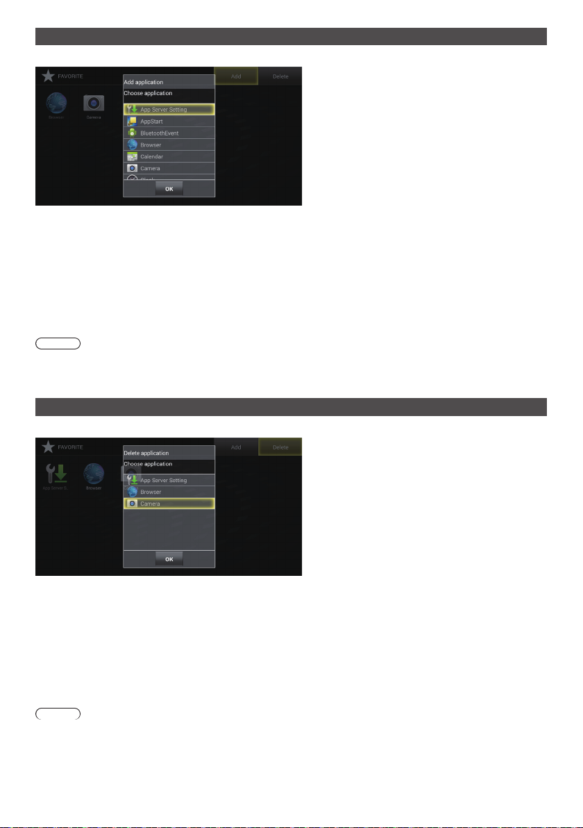
Adding the application to [FAVORITE]
Adds the installed application to [FAVORITE].
Select [Add] and press <ENTER>.
1
Displays the [Add application] dialogue.
Select the application to add and press <ENTER>.
2
Adds the selected application. Multiple applications can be selected in a row.
Select [OK] and press <ENTER>.
3
The dialogue is closed.
It is also possible to close the dialogue by pressing <BACK>.
Note
●
Installing the application will automatically add the application to [FAVORITE].
●
The shortcut (see page 60) is also added to [FAVORITE].
Deleting the application from [FAVORITE]
Deletes the application from [FAVORITE].
Select [Delete] and press <ENTER>.
1
Displays the [Delete application] dialogue.
Select the application to delete and press <ENTER>.
2
Deletes the selected application. Multiple applications can be selected in a row.
Select [OK] and press <ENTER>.
3
The dialogue is closed.
It is also possible to close the dialogue by pressing <BACK>.
Note
●
The deleted application only disappears from [FAVORITE], and can be added again with [Add].
●
The shortcut (see page 60) can also be deleted. The deleted shortcut cannot be added to [FAVORITE] again by
selecting [Add].
50
Page 51

[RECENTS] screen of OpenPort PLATFORM
Select the [RECENTS] button icon on the home screen to display the [RECENTS] screen.
The recently used applications are displayed with icons.
When the OpenPort PLATFORM system is shut down (see page 40), the history is cleared.
Select the application to start up, and press <ENTER>.
The application starts up.
Deleting the application from [RECENTS]
Deletes the application from [RECENTS].
Select [Delete] and press <ENTER>.
1
Displays the [Delete application] dialogue.
Select the application to delete and press <ENTER>.
2
Deletes the selected application. Multiple applications can be selected in a row.
Select [OK] and press <ENTER>.
3
The dialogue is closed.
It is also possible to close the dialogue by pressing <BACK>.
■ Deleting all the applications from [RECENTS]
Select the [All Delete] button, and press <ENTER>.
Deletes all the applications for [RECENTS], and moves to the home screen.
51
Page 52

[STATUS] screen of OpenPort PLATFORM
Select the [STATUS] button icon on the home screen to display the [STATUS] application screen.
The model information and network-related setting information of this unit can be confirmed.
Scroll the screen to display the following information.
■ [MODEL INFO] ■ [ETHERNET] ■ [WI-FI]
[Model name] [IP address] [IP address]
[Serial number] [MAC address] [MAC address]
QR code
([Model name], [Serial number],
[MAC address] of [ETHERNET])
Note
●
Data of QR code can be read by taking
the picture using a camera of mobile
phone, etc. The reading quality is
affected by the performance of camera or
application.
■ [SUPPORT]
Select [Check Communication] or [Log].
[Check Communication]
Select [ping], [nslookup] or [traceroute] to perform.
[ping]: Input the IP address to [Host], and select [Execute]. Then, the response from the sender is displayed.
[nslookup]: Input the address name to [Host], and select [Execute]. Then, you can check if the DNS problem is
[traceroute]: Input the address name to [Host], and select [Execute]. Then, the network path to the specified Host is
[Log]
Saves log to a USB memory (USB (OpenPort PLATFORM) terminal).
This is a function for the technical support.
solved.
displayed.
[DNS 1] [DNS 1]
[DNS 2] [DNS 2]
[IP settings] [IP settings]
[Proxy hostname] [Proxy hostname]
[Proxy port] [Proxy port]
[DHCP] [DHCP]
52
Page 53

Pre-installed Applications of OpenPort PLATFORM
Pre-installed application list
Application name Location Type Description
SETUP Home Panasonic
INSTALLER Home Panasonic
STATUS Home Panasonic
LAN Control TOOLS Panasonic
Settings TOOLS Android
CreateShortcut TOOLS Panasonic
AppStart TOOLS Panasonic
App Server Setting TOOLS Panasonic
Shutdown TOOLS Panasonic
Updater TOOLS Panasonic
1
SignageBrowser
Version
Browser
Camera
Clock
Downloads
Gallery
Music
People
Search
Sound Recorder
Calendar
BluetoothEvent
1 Register to [FAVORITE] for using. (see page 50)
*
2 This unit unique application.
*
3 Android standard, AOSP (Android Open Source Project) application
*
*
1
*
FAVORITE
(Factory default)
FAVORITE
(Factory default)
1
*
1
*
1
*
1
*
1
*
1
*
1
*
Panasonic
Panasonic
Android
Android
Android
Android
Android
Android
Android
Android
Android
Android
Android
Note
●
Some applications cannot be operated with the remote control. In this case, use a USB mouse (commercially
available). (see page 43)
Sets [WIRELESS & NETWORKS], [Language & input] and
2
*
[Date & time settings]. (Same as a part of [TOOLS] - [Settings])
(see page 46)
2
*
Use this when installing a new application. (see page 47)
The model information of this unit and network-related setting
2
*
information can be confirmed. (see page 52)
Sets [ON]/[OFF] of [Command Control], [Control Protocol], [Port
2
*
number], [Display name], [User name] and [Password] via LAN
of this unit. (see page 54)
3
*
Makes various settings for Android OS. (see page 55)
Creates shortcuts to access specified URLs by browser. (see
2
*
page 60)
Specifies the URL (browser) or application to launch first when
2
*
the OpenPort PLATFORM system starts up. (see page 60)
Makes the setting to link with the application server. (see page
2
*
61)
Forcibly shuts down the OpenPort PLATFORM system. (see
2
*
page 61)
Use this when updating the firmware of the OpenPort
2
*
PLATFORM system of this unit. (see page 61)
This is a WEB browser compatible with HTML5 customized for
2
*
signage use. (see page 61)
Displays the uboot version, kernel version and system version
2
*
of the OpenPort PLATFORM system firmware of this unit. (see
page 62)
3
*
Displays WEB pages for browsing. (see page 62)
Connect a USB camera (commercially available) to the USB
3
*
(OpenPort PLATFORM) terminal for using. (see page 62)
3
*
Displays clock, set alarm, etc.
Displays the list of the files which have been downloaded from
3
*
WEB sites.
3
*
Displays still picture or motion picture for browsing.
3
*
Plays back music.
3
*
Manages contacts.
3
*
Used for searching.
3
*
Records sounds.
3
*
Internal application. No need to start up.
3
*
Internal application. No need to start up.
53
Page 54
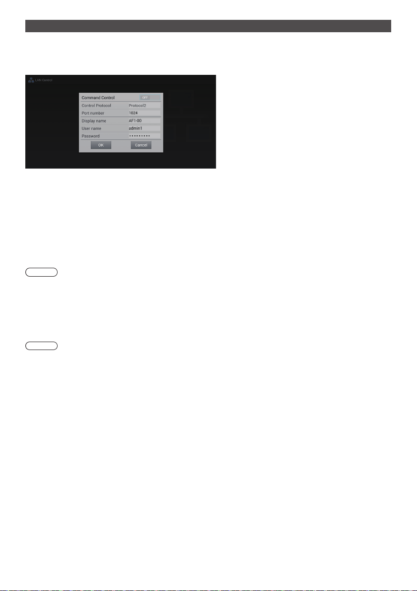
[LAN Control] application
This unit unique application. Select the [LAN Control] button icon on the [TOOLS] screen to display the [LAN Control]
screen.
Sets [ON]/[OFF] of [Command Control], [Control Protocol], [Port number], [Display name], [User name] and [Password]
via LAN of this unit.
■ [Command Control]
Set this to [ON] when performing the command control of this unit (see page 98) via network.
[ON]: Enables the command control.
[OFF]: Disables the command control.
■ [Control Protocol]
Select the protocol for the LAN control.
[Protocol1]: Controls with the sequence of the Panasonic display.
[Protocol2]: Controls with the sequence compatible with the Panasonic projector.
Note
●
PJLink can be operated regardless of the [Control Protocol] setting.
●
When performing the command control with TCP/IP, select [Protocol1].
●
When operating the “Early Warning Software” or “Multi Monitoring & Control Software”, select [Protocol2].
■ [Port number]
Set the port number to use for the command control.
Setting range: 1024 (Default) to 65535 (excluding 4352)
Note
●
When using PJLink, the port setting is not necessary.
■ [Display name]
Set the name of this unit displayed on the network.
■ [User name]
Set the user name added to the command.
(Default: admin1)
■ [Password]
Set the password used for the command control and PJLink security authentication.
(Default: panasonic)
54
Page 55

[Settings] application
Android standard application. Select the [Settings] button icon on the [TOOLS] screen to display the [Settings] screen.
Note
●
Some functions are not available on this unit.
Make various settings for Android OS.
Select the setting item and press <ENTER> to display the setting screen.
Scroll the screen to display the following items.
■ [WIRELESS & NETWORKS]
Make various settings for network.
This can be set by selecting [SETUP] - [WIRELESS & NETWORKS] as well. (see page 46)
[Wi-Fi]
To enable the Wi-Fi function, set the [OFF/ON] button to [ON].
The access point list in your area is displayed. Selecting the connection destination displays the security password
setting dialogue.
[Password]: Enter the password.
[Show password]: Displays the input password when a check mark is added to the check box.
[Show advanced options]: Displays [Proxy] and [IP settings] when a check mark is added to the check box.
[Connect]: Connects to the selected access point.
[Cancel]: Cancels the connection, and returns to the access point list display.
[Proxy]:
[None]: The proxy is not set.
[Manual]: The proxy is set manually.
[Proxy hostname]: Sets the host name of proxy.
[Proxy port]: Sets the port number of proxy.
[Bypass proxy for]: Sets the domain that does not use the proxy.
[IP settings]:
[DHCP]: Acquires the IP address automatically if a DHCP server is present on the network where
[Static]: Sets the IP address manually if a DHCP server is not present on the network where the
[IP address]: Sets the IP address if a DHCP server is not used.
[Gateway]: Sets the gateway address if a DHCP server is not used.
[Network prefix length]: Sets the network prefix length if a DHCP server is not used.
[DNS 1]: Sets the priority DNS server address if a DHCP server is not used.
[DNS 2]: Sets the substitute DNS server address if a DHCP server is not used.
[WPS Push Button]
Use this when connecting to the access point device compatible with WPS.
Selecting [WPS Push Button] will make the access point device enter the WPS button standby mode.
For operation of the access point device, read the operating instructions supplied with the device.
the display is connected.
display is connected.
55
Page 56

+ button
Adds the access point.
If the access point you wish to connect cannot be found on the list, set the following with manual input.
Selecting + button will display the setting menu of the network to add.
[Network SSID]: Enter the SSID.
[Security]: Select the encryption method from the following.
[None], [WEP], [WPA/WPA2 PSK], [802.1x EAP]
[Show advanced options]: Displays [Proxy] and [IP settings] when a check mark is added to the check box.
Menu button
Select the menu button to display the following items.
[Scan]: Searches for access points in your area again, and displays them on the list.
[WPS Pin Entry]: Use this when connecting to the access point device compatible with WPS.
A PIN code is displayed in the message displayed when this is selected. Input the PIN
code into the access point device within 2 minutes.
For operation of the access point device, read the operating instructions supplied with
[Wi-Fi Direct]: Directly communicates between Wi-Fi devices without the access point device.
[Advanced]: Displays the option settings related to Wi-Fi communication.
Note
●
When [IP settings] is set to [DHCP], the IP address, etc. are not displayed. Confirm the current IP address, etc. in
[STATUS]. Also, the DNS set on this screen will be invalid.
●
When using a DHCP server, confirm that the DHCP server has started up.
●
For setting details, consult the network administrator.
●
The wired LAN and wireless LAN cannot be used in the same segment.
the device.
Selecting this will display usable devices on the list. Select the device to connect.
56
Page 57

[Ethernet]
■ [DEVICE]
[DHCP]
[ON]: Acquires the IP address automatically if
a DHCP server is present on the network
where the display is connected.
[OFF]: Sets the IP address manually if a DHCP
server is not present on the network where
the display is connected.
[IP address]: Input the IP address if not using a
[Gateway]: Input the gateway address if not using a
[Subnet mask]: Input the subnet mask if not using a
[DNS 1]: Input the priority DNS server address if
[DNS 2]: Input the substitute DNS server address
[OK]: Saves the setting, and returns to the
[Cancel]: Returns to the [Settings] screen without
Note
●
When [DHCP] is set to [ON], items for the IP address,
gateway, subnet mask and DNS are greyed out.
●
When using a DHCP server, confirm that the DHCP
server has started up.
●
If an invalid IP address, gateway or subnet mask
is set, selecting [OK] will display the following error
message.
[INVALID ENTRY. PLEASE RE-ENTER.]
●
If the IP address is conflicting, selecting [STATUS] [ETHERNET] - [IP address] (see page 52) will display
the following error message.
[IP address conflict with another system on the
network.]
●
For setting details, consult the network administrator.
●
The wired LAN and wireless LAN cannot be used in
the same segment.
DHCP server.
DHCP server.
DHCP server.
not using a DHCP server.
if not using a DHCP server.
[Settings] screen.
saving the setting.
[Home]
Sets the home screen. Use a USB mouse for setting.
[Launcher]: Android standard home screen
[QuickLauncher]:
Recommended home screen for this unit
(see page 63)
(Factory default) (see page 45)
[Sound]
Sets the touch operation sound when using a USB
mouse.
[Touch sounds]: Add a check mark for the check box to
enable the touch operation sound.
[Display]
Select the setting item and press <ENTER> to display
the setting screen.
[Wallpaper]
Select a wallpaper from the following 3 items.
[Gallery]: Select a wallpaper from image files in
[Live
Wallpaper]:
[Wallpaper]: Select a wallpaper of still picture.
Note
●
The wallpaper is displayed only on the Android
standard home screen, etc.
[Daydream] (This function cannot be used.)
[Font size]
Select the character size from the following 4 types.
[Small], [Normal], [Large], [Huge]
[Cancel]: Returns to the [Display] function list screen
[Gallery].
Select a wallpaper with motion.
without saving the setting.
[Proxy]
[Proxy hostname]: Sets the host name of proxy.
[Proxy port]: Sets the port number of proxy.
[Bypass proxy for]: Sets the domain that does not use
[OK]: Saves the setting, and returns to the [Settings]
screen.
[Cancel]: Returns to the [Settings] screen without saving
the setting.
Note
●
For setting details, consult the network administrator.
the proxy.
[Storage]
Displays the current storage usage ([INTERNAL
STORAGE], microSD card, [USB STORAGE]).
[INTERNAL STORAGE]
[SD CARD]
When removing the microSD card, unmount it here for
safe removal.
[USB STORAGE]
When removing the USB memory, unmount it here for
safe removal.
57
Page 58

Note
●
When attaching or removing a microSD card or a
USB memory, an SD card shaped icon or warning
messages will be displayed at the upper left of the
screen. As a general term, they are called “SD card”
in the message.
●
As for USB memory, it is also called “SD card” even
though it is displayed in [USB STORAGE] category.
[Apps]
Displays the application list. Operate right and left, and
select the list from the following 3 items.
[DOWNLOADED]: Already installed application list
[RUNNING]: Operating application list
[ALL]: All application list
Stops, disables and deletes the application.
Uninstallation is possible only for installed applications.
■ [PERSONAL]
[Location]
To enable the function to acquire location information,
set the [OFF/ON] button to [ON].
[Mode] (This function is only available with Wi-Fi.)
[Security]
Makes the security-related settings.
[SCREEN SECURITY]
[Screen lock]:
Selects the screen lock method.
Once the screen lock is set, you will need to unlock it
when performing [Factory data reset].
[Owner info]: (This function cannot be used.)
[ENCRYPTION] (This function cannot be used.)
[PASSWORDS] (This function cannot be used.)
[DEVICE ADMINISTRATION]
[Device administrators]: (This function cannot be
[Unknown sources]:
Permits installation of unknown applications when a
check mark is added to the check box.
[Verify apps]: (This function cannot be used.)
used.)
[CREDENTIAL STORAGE]
[Storage type]:
Software only
[Trusted credentials]:
Displays the reliable CA certificate.
[Install from SD card]:
Installs the certificate from the microSD card and USB
memory.
[Clear credentials]:
Deletes all the certificates.
[Language & input]
Sets the language to use, input method, etc.
This can be set by selecting [SETUP] - [Language &
input] as well. (see page 46)
Select the setting item and press <ENTER> to display
the setting screen.
[Language]
Select the language to use from the language list.
Selectable languages
[Deutsch]: German
[English (United Kingdom)]: English (UK)
[English (United States)]: English (US)
[Español]: Spanish
[Français]: French
[Italiano]: Italian
[Русский]: Russian
[中文]: Chinese
[日本語]: Japanese
Note
●
This is set while interlocking [Setup] - [OSD
language]. (see page 83)
[Spell checker]
Select whether to use the spell check during character
input.
[Personal dictionary]
Displays the user dictionary list. Select the user
dictionary to register.
Select the [ADD] button to display the word registration
screen. Then, register the word.
[KEYBOARD & INPUT METHODS]
When [Default] is selected, [Choose input method]
screen is displayed. Select the input method.
[Android Keyboard (AOSP)]:
Android standard software keyboard.
[OpenPort keyboard]
OpenPort PLATFORM-unique software keyboard.
58
Page 59

Note
●
Connecting a USB keyboard will display the setting
items of physical keyboard. Select the connected
keyboard here to display the [Choose keyboard
layout] screen.
Select [Set up keyboard layouts], set language in
[Keyboard layouts] to complete the setting.
[SPEECH]
Displays the text-to-speech reading output setting
screen when [Text-to-speech output] is selected.
[MOUSE/TRACK PAD]
Displays the screen to set the pointer speed when
[Pointer speed] is selected.
Move the slider and select [OK]. Then, the setting is
applied.
[Backup & reset]
Each setting and data of the OpenPort PLATFORM part
can be restored to the factory default state.
Selecting [Backup & reset] displays the [PERSONAL
DATA ] screen.
[Factory data reset]
Select [Factory data reset] and press
1
<ENTER>.
A confirmation screen is displayed to inform that
each type of data will be deleted.
■ [SYSTEM]
[Date & time]
Sets the date and time.
This can be set by selecting [SETUP] - [Date & time
settings] as well. (see page 46)
Selecting [Date & time] displays the setting screen of
date and time.
[Automatic date & time]
Adding a check mark to the check box can use the date
and time offered by the network. However, it will be
required to set the time zone. Set manually.
[Set date]
Sets the date manually. Use a USB mouse for setting.
If [Automatic date & time] is checked, this item is greyed
out.
[Set time]
Sets the time manually. Use a USB mouse for setting.
If [Automatic date & time] is checked, this item is greyed
out.
[Select time zone]
Sets the time zone manually.
[Use 24-hour format]
Shows the 24-hour display at the OpenPort PLATFORM
part when a check mark is added to the check box.
Select [Reset tablet] and press
2
<ENTER>.
The final confirmation screen appears.
Select [Erase everything] and press
3
<ENTER>.
The OpenPort PLATFORM system restarts, and the
settings are restored to the factory default state.
Note
●
The following settings and adjusted values will not be
changed even if this function is performed.
[Picture], [Sound], [Setup], [Position] and [Options]
menus.
To restore these settings to the factory default state,
perform [Shipping]. (see page 113 )
●
When [Screen lock] is set, you will need to unlock it.
(see page 58)
[Choose date format]
Select the date display format.
Note
●
The time can be set up to [2037/12/31 23:59].
If the time reaches [2038/1/1 00:00:00], the unit does
not operate normally.
●
If the clock shows wrong time soon after set to the
right time, replace the battery inside the unit. Consult
the dealer where you purchased the product.
[Accessibility]
Selecting [Accessibility] displays the setting screen to
assist the user.
[SERVICES]
Displays the service information.
[SYSTEM]
[Captions]: Makes each setting for subtitles.
[ON] / [OFF]
[Language]
[Text size]
[Caption style]
59
Page 60

[Magnification gestures]: (This function cannot be
used.)
[Large text]:
Enlarges the character size displayed on the screen
when a check mark is added to the check box.
[Speak passwords]:
Outputs the password with sound when a check mark
is added to the check box.
[Accessibility shortcut]: (This function cannot be
used.)
[Text-to-speech output]:
Same setting as [Settings] - [Language & input] [SPEECH] (see page 59)
[Touch & hold delay]
Sets the time period to press and hold the left button
of the USB mouse.
[About tablet]
Displays the following information of OpenPort
PLATFORM when [About tablet] is selected.
[Status]
Select [Status] to display the information of network, etc.
[Legal information]
Select [Legal information] to display the open-source
license information.
[Model number]
Displays the model number.
[Android version]
Displays the Android version.
[Kernel version]
Displays the kernel version.
[Build number]
Displays the build number.
[CreateShortcut] application
This unit unique application. This application has been
registered to [TOOLS].
Creates shortcuts to access specified URLs by browser.
■ To create a shortcut
Input [Shortcut Name] and [URL].
1
[AppStart] application
This unit unique application. This application has been
registered to [TOOLS].
Specifies the URL (browser) or application to launch
first when the OpenPort PLATFORM system starts up
automatically.
■ Switching ON/OFF to start up the browser
or application at the startup of system.
[ON]: Starts up the URL (browser) or application
specified at the startup of system.
[OFF]: Starts up nothing at the startup of system.
■ Starting up the browser or application at
the startup of system.
Select [Browser] or [Application] and
1
press <ENTER>.
[Browser]: Launches the browser at startup.
[Application]: Launches the application at startup.
Select the URL or application to
2
launch from the list, and press
<ENTER>.
Confirm that the URL or application to
3
launch has been registered, and set
the ON/OFF switch to [ON].
■ To add an URL
Input the URL.
1
Select [Add] and press <ENTER>.
2
The URL is added to the list.
■ To delete an URL
Select [Delete Item…] and press
1
<ENTER>.
Select the URL to delete from the URL
2
list, and press <ENTER>.
Select [Create] and press <ENTER>.
2
The shortcut is created in [FAVORITE].
■ To delete a shortcut
Selecting [FAVORITE] - [Delete] can delete the
registration.
60
Page 61

[App Server Setting] application
This unit unique application. This application has been
registered to [TOOLS].
Makes the setting to link with the application server.
■ [Request execution time]
Sets the time to send a query to the application server.
[00:00] to [23:59]
Automatically sends a query to the application server at
the set time, and performs update if necessary.
■ [Request ban]
Prohibits sending a query when a check mark is added
to the check box.
■ [Request execution]
Sends a query immediately after [Request execution] is
selected.
The progress bar is displayed while sending the query,
and other operations are not available during that time.
[Shutdown] application
This unit unique application. This application has been
registered to [TOOLS].
Forcibly shuts down the OpenPort PLATFORM system.
The confirmation message asking [Do you want to shut
down?] appears.
[OK]: Starts the shutdown processing.
The power indicator lights up in orange from
green illumination, and the message [Shutting
down OpenPort PLATFORM. Please wait.]
appears.
While the OpenPort PLATFORM system is
shutting down, the remote control operation or
external control commands are not accepted.
When the shutdown is complete, this unit turns
off. The power indicator lights up in red, entering
the standby state.
[Cancel]: Returns to the [TOOLS] screen without
shutting down.
[Updater] application
This unit unique application. This application has been
registered to [TOOLS].
Use this when updating the firmware of the OpenPort
PLATFORM system of this unit.
Displays the file list of external storage (microSD card,
USB memory (USB (OpenPort PLATFORM) terminal)).
●
Select [Search Again] to search the external storage
again, then the list will be displayed.
●
The extension of update file is zip.
Select the update file from the displayed list, and
press <ENTER>.
A confirmation message is displayed. Select [OK] to
start the preparation for update. Then, the progress bar
is displayed.
When the progress bar reaches 100%, the OpenPort
PLATFORM system is reset, and the system to execute
begins to be installed.
When the system installation is complete, it is reset
again, and restarts.
Note
●
Even if the firmware is updated, each setting of
OpenPort PLATFORM is not changed.
[SignageBrowser] application
This unit unique application. Register to [FAVORITE] for
using. (see page 50)
This is a WEB browser compatible with HTML5
customized for signage use.
Create the shortcut specifying the URL beforehand by
selecting [TOOLS] - [CreateShortcut] ([CreateShortcut]
application). (see page 60)
Performing the shortcut displays the selection dialogue
of the WEB browser to use.
Select [SignageBrowser] on the selection dialogue
to connect to the signage WEB server, and this is
displayed.
If [Always] is selected on the selection dialogue of
the WEB browser, the selection dialogue of the WEB
browser is no longer displayed.
Note
●
Startup the application after confirming the connection
to network.
If the network setting is performed after the
application is started up, network connection is not
possible. In this case, delete the application on
[RECENTS] screen (see page 51, 63), and then
startup the application again to connect.
●
To display WEB pages for browsing, use the
[Browser] application.
61
Page 62

[Version] application
This unit unique application. Register to [FAVORITE] for
using. (see page 50)
Displays the following versions of the OpenPort
PLATFORM system firmware.
uboot version, kernel version and system version
Further details of the kernel version can be confirmed
by selecting [TOOLS] - [Settings] - [About tablet]. (see
page 60)
[Browser] application
Android standard application. As factory default, this
application is registered as [FAVORITE].
Displays WEB pages for browsing.
[Camera] application
Android standard application. As factory default, this
application is registered as [FAVORITE].
Connect a USB camera (commercially available) to the
USB (OpenPort PLATFORM) terminal for using. If not
connected, the [Camera error] message will appear.
62
Page 63
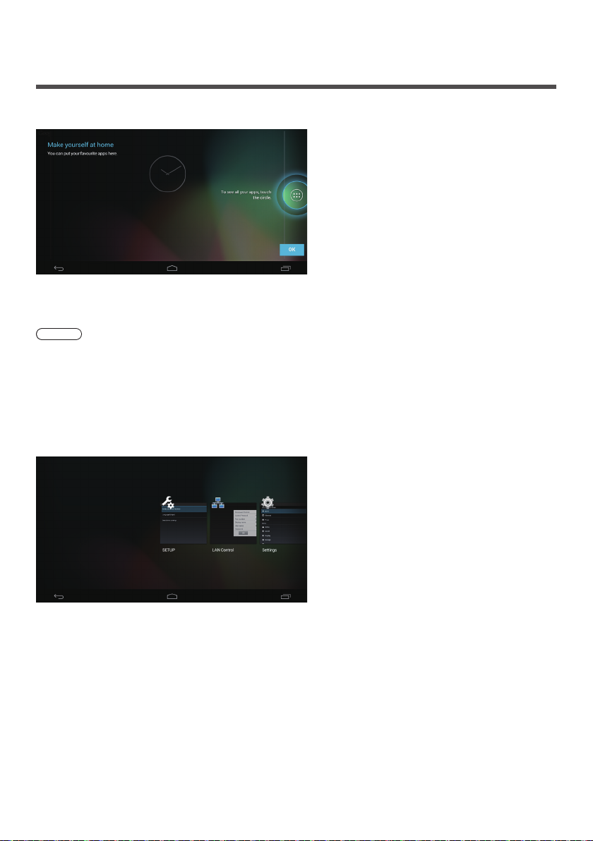
Android Standard Home Screen of OpenPort PLATFORM
When the Android standard home screen is selected for the OpenPort PLATFORM home screen, the tutorial screen is
displayed at first.
Click the [OK] button on the tutorial screen using a USB mouse (commercially available) (see page 43) to exit the
tutorial screen. Then, the operation with remote control, USB mouse, etc. will be possible.
Note
●
When the Android standard home screen is selected, the remote control operation is restricted. Operation using a
USB mouse is more convenient.
■ Android standard [RECENTS] screen
Click [RECENT APPS] (see page 44) of operation icon using a USB mouse to display the application screen (Android
standard screen) recently used.
When the OpenPort PLATFORM system is shut down (see page 40), the history is cleared.
The application can be started up by clicking with the USB mouse.
If the application is swiped and removed to the outside the screen using the USB mouse, this application can be
deleted from this screen.
63
Page 64

ASPECT Controls
Press <ASPECT> or <ENTER (Unit)> repeatedly to
move through the aspect options:
Unit
INPUT
MENU
ENTER
[4:3]→[Zoom1]→[Zoom2]→[16:9]
Note
●
The aspect mode is memorised separately for each
input terminal.
●
When input from USB, the aspect mode is fixed to
[16:9].
●
When input from OpenPort PLATFORM, the aspect
mode is fixed to [16:9].
■ List of Aspect Modes
Aspect mode Description
Picture
Enlarged
screen
Aspect mode Description
Pictures are displayed in the 4:3
area. Pictures with a 4:3 aspect ratio
are displayed as is. PC signals are
enlarged or reduced to be displayed
in the 4:3 area. Side panels are
4:3
Zoom1
Zoom2
displayed both at the right and left
edges of the screen.
Pictures with a 4:3 aspect ratio in
16:9 signals are displayed with their
original aspect ratio. The left and right
edges of the pictures are masked by
side panels.
Letterbox pictures with a 16:9 aspect
ratio are enlarged vertically to fill the
screen. The top and bottom edges of
the pictures are cut off.
Letterbox pictures with a 16:9 aspect
ratio are enlarged vertically and
horizontally to fill the screen. The top
and bottom edges as well as the left
and right edges of the pictures are
cut off.
64
16:9
English
Pictures are displayed filling the
screen.
Note
●
Do not allow the picture to be displayed in 4:3
mode for an extended period, as this can cause a
permanent image retention to remain on the Display
Panel.
●
Be aware that if you put the display in a public place
for commercial purposes or a public showing and
then use the aspect mode select function to shrink
or expand the picture, you may be violating the
copyright under copyright law. It is prohibited to show
or alter the copyrighted materials of other people for
commercial purposes without the prior permission of
the copyright holder.
●
In [ENGLISH(US)] OSD language, [16:9] is displayed
as [FULL].
Page 65

Digital ZOOM
Select the screen areas (25 areas) to zoom in, and
zoom in the selected image areas ×2, ×3 or ×4.
(Use the remote control. The main unit’s buttons cannot
be used for operation.)
Enter
Select
Exit
Digital Zoom
Set the digital zoom mode.
1
Press <ZOOM>.
Exit
RETURN
×1
ENTER
The screen aspect is set to [16:9], and the digital
zoom operation guide is displayed.
Select the image areas to zoom in.
2
Select pressing .
RETURN
ENTER
Digital Zoom operation guide
Exit
×1
Switch the zoom ratio for the screen
3
areas.
Switches every time <ENTER> is pressed.
Exit
×1
×1 ×2 ×3 ×4
●
If no operation is performed for approx. 60
seconds when the zoom ratio for the screen is
“×1”, the unit exits the zoom mode.
●
If no operation is performed for approx. 3 seconds
when the zoom ratio for the screen is “×2”,
“×3” or “×4”, the digital zoom operation guide
display disappears. Pressing any of the
buttons displays the guide again.
Exit the digital zoom mode.
4
Press <RETURN> to exit the mode.
The screen returns to the previous state just before
entering the digital zoom mode, and the digital zoom
operation guide display disappears.
●
Press any of the following buttons to exit the
mode. Then, the operation of the pressed button
is performed.
Remote Control:
<AUTO SETUP> <POSITION> <PICTURE>
<INPUT> <SETUP> <SOUND>
<DEFAULT> <RECALL> <MUTE>
<ASPECT> <OFF TIMER> <FUNCTION>
<VOL +> <VOL -> <1>-<6>
Unit:
<INPUT (Unit)> <MENU (Unit)> <+ (Unit)>
<- (Unit)>
●
When the screen saver timer starts up, the digital
zoom mode finishes.
●
When the power is turned OFF, a force-quit is
performed.
When the power is turned OFF by pressing the
•
<Standby (ON/OFF) button>.
When the display is turned OFF at the <Main
•
Power On / Off button>
When the power is turned OFF by the off-timer
•
When the power is turned OFF by [No signal
•
power off] or [Power management].
Exit
×2
<ENTER (Unit)>
Exit
×3
Exit
×4
Note
●
In the following cases, the digital zoom mode is not
available.
When [Multi display setting] is [On]
•
When the screen saver is in operation
•
When USB input is selected.
•
●
The zoomed image is rougher than the original
image.
●
For multi display use, use the functions in [Multi
display settings]. (see page 84)
English
65
Page 66
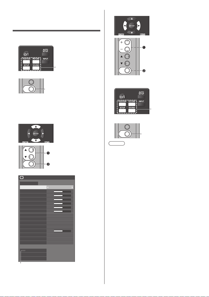
On-Screen Menu Displays
Display the menu screen.
1
Remote Control
Set.
3
Press to select.
Press to select.
Unit
INPUT
MENU
Press for several times.
Each time the button is pressed, the menu screen
will switch.
NormalViewing→[Picture]→[Setup]→[Position]
→[Sound]
Select the item.
2
Press to select.
ENTER
Press.
(Example: [Picture] menu)
Picture
Default Default
Picture mode Standard
Backlight
Contrast
Brightness
Colour
Hue
Sharpness
Gamma
Colour temperature
6-segment colour management
Dynamic contrast
Colour enhancement
Refine enhancer
Gradation smoother
Memory save
Memory load
Memory edit
50
50
50
50
50
50
HighEnhance level
2.2
6500K
Off
5
Off
Off
Off
Submenu
Press <ENTER> to display the submenu.
ENTER
Exit from the menu.
4
Press.
Press.
Press <RETURN> to return to the previous screen.
INPUT
MENU
Press for several times.
Note
●
When changing the settings of the display, picture or
sound disturbance may occur temporarily. This is not
a malfunction.
66
English
Page 67
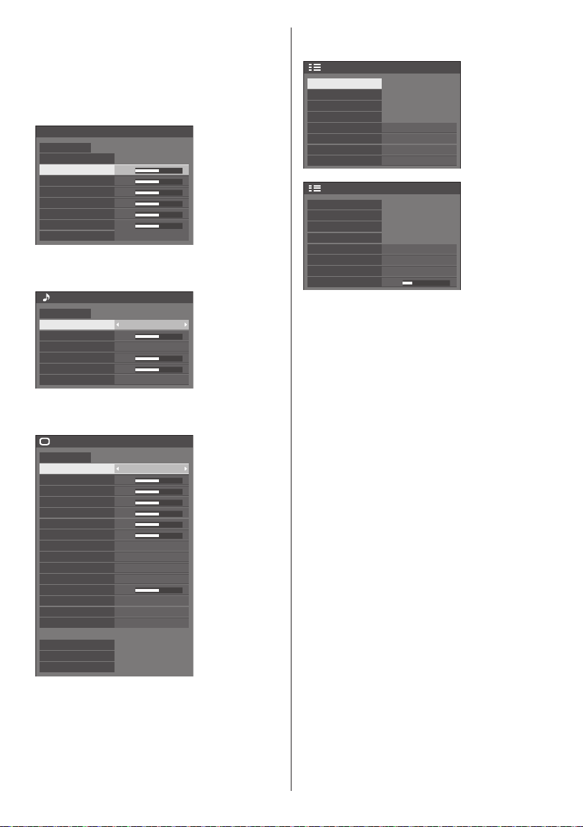
Menu display list
●
Menu that cannot be adjusted is greyed out.
Adjustable menu changes depending on signal, input
and menu setting.
[Position] menu
(see page 68 - 69)
Position
Default Default
Auto setup
H-position
H-size
V-position
V-size
Clock phase
Dot clock
1:1 pixel mode
0
0
0
0
15
0
Off
[Sound] menu
(see page 70)
Sound
Default Default
Output select SPEAKERS
Balance
Sound mode
Bass
Treble
Surround
0
Normal
0
0
Off
[Picture] menu
(see page 71 - 77)
Picture
Default
Default
Picture mode Standard
Backlight
Contrast
Brightness
Colour
Hue
Sharpness
Enhance level High
Gamma
Colour temperature 6500K
6-segment colour management
Dynamic contrast
Colour enhancement
Refine enhancer
Gradation smoother
Memory save
Memory load
Memory edit
50
50
50
50
50
50
2.2
Off
5
Off
Off
Off
[Setup] menu
(see page 78 - 87)
Setup
Signal
Screensaver
Input label
Power management settings
OpenPort PLATFORM standby
Wobbling
No activity power off
OSD language
Setup
Multi display settings
Set up timer
USB media player settings
Function button settings
Display orientation
OSD position
Menu display duration
Menu transparency
English(UK)
Landscape
20
Off
Off
Disable
Right
60 sec
1/2
2/2
English
67
Page 68

Adjusting Position
Press <POSITION> to display the
1
[Position] menu.
Position
Default Default
Auto setup
H-position
H-size
V-position
V-size
Clock phase
Dot clock
1:1 pixel mode
Select the item to adjust with .
2
●
Unadjustable items are greyed out.
Adjustable items differ depending on the signal,
input and the display mode.
Adjust with .
3
Press <POSITION> to exit from adjust
4
mode.
■ To return to the previous screen
Press <RETURN>.
■ To reset to defaults
Press <DEFAULT> while the menu is displayed, or
press <ENTER> when [Default] is selected, then the
settings will be set to factory settings.
Note
●
Settings for [Position] are memorised separately for
each input signal.
Setting [Position] when the display is installed
vertically
When adjusting, please note that even when the
display is installed vertically, setting directions of
position / size are the same as that of horizontal
installation.
0
0
0
0
15
0
Off
Auto setup
When inputting a PC signal, [H-position] / [V-position],
[H-size] / [V-size], [Clock phase] and [Dot clock] are
automatically corrected.
This setting is enabled under the following
condition:
●
When inputting from PC IN or RGB IN
While displaying the picture of the corresponding
signal, select [Auto setup] and press <ENTER>.
Using Remote Control
Press <AUTO SETUP>.
When Auto Setup does not work, [Invalid] is
displayed.
Auto mode
When the [PC auto setting] is set to [On] in the [Options]
menu (see page 93), automatic position adjustment
starts under the following conditions:
●
When the display power is turned ON.
●
When the input signal is switched.
Note
●
When the dot clock frequency of a PC signal is 162
MHz or higher, [Clock phase] and [Dot clock] cannot
be automatically corrected.
●
Auto Setup may not work when a cropped or dark
image is input. In such case, switch to a bright image
with borders and other objects are clearly shown, and
then try auto setup again.
●
Depending on the signal, out of alignment may occur
after Auto Setup. Carry out fine tuning for the position/
size as required.
●
If Auto Setup cannot set properly for XGA signal
(1024×768, 1280×768, 1366×768), pre-selecting the
individual signal in [XGA mode] (see page 79) may
results in correct Auto Setup.
●
Accurate auto setup is not possible when a signal
such as additional information is superimposed out
of valid image period or when intervals between
synchronizing signal and image signal are short.
Also, accurate auto setup is not possible when image
signals with tri level synchronizing signal added, or
when some SYNC ON G signals are input.
●
If Auto Setup does not work well, select [Default],
press <ENTER>, and then adjust the position/size
manually.
68
English
Page 69

[H-position] Adjust the horizontal position with .
[H-size] Adjust the horizontal size with
[V-position] Adjust the vertical position with .
[V-size] Adjust the vertical size with .
.
Note
●
In some cases, noise appears outside the area
picture is displayed, but it is not a malfunction.
[Clock
phase]
[Dot clock] (For RGB IN or PC IN input)
[Over scan] Turn image over scan On/Off.
[1:1 pixel
mode]
(For RGB IN or PC IN input)
In some cases, frame of the screen
appears blurred or smudged, when RGB
signal or PC signal are input.
Periodic striped pattern interference
(noise) may occur when a striped pattern
is displayed. If this happens, adjust so
that any such noise is minimized.
Applicable input signal:
525i, 525p, 625i, 625p, 750/60p, 750/50p
(Component Video, RGB, DVI-D, HDMI)
[On] [Off]
Note
●
When [Off] is set, [H-size] and [V-size]
cannot be adjusted.
Adjusts the display size when 1125i or
1125p signal is input.
[Off] [On]
Applicable input signal:
1125 / 50i, 60i, 24PsF, 24p, 25p, 30p,
50p, 60p
Note
●
Select [Off] when flickering is shown
around the image.
●
[H-size] and [V-size] cannot be
adjusted when [On] is selected.
English
69
Page 70

Sound Adjustment
Press <SOUND> to display the
1
[Sound] menu.
Sound
Default Default
Output select SPEAKERS
Balance
Sound mode
Bass
Treble
Surround
Select the item to adjust with .
2
●
Menu that cannot be adjusted is greyed out.
Adjust with .
3
Press <SOUND> to exit from adjust
4
mode.
■ To return to the previous screen
Press <RETURN>.
■ To reset to defaults
Press <DEFAULT> while the menu is displayed, or
press <ENTER> when [Default] is selected, then the
settings will be set to factory settings.
[Output select] Select the audio output.
[Balance] Adjusts left and right volumes.
[Sound mode] Select for best audio.
●
In [ENGLISH(US)] OSD language, [Sound mode]
and [Normal] are displayed as [AUDIO MENU] and
[STANDARD].
[Bass] Adjusts low pitch sounds.
[Treble] Adjusts high pitch sounds.
0
Normal
0
0
Off
[SPEAKERS]:
Internal speakers
[AUDIO OUT]:
AUDIO OUT terminal output
●
When [AUDIO OUT] is selected,
the other menus are greyed out
and cannot be selected.
●
Audio volume setting is
memorized separately for each
output.
[Normal]:
Emits the original sound.
[Dynamic]:
Accentuates sharp sound.
[Clear]:
Attenuates human voice.
[Surround] [Off]:
Normal sound
[On]:
Surround sound
Note
●
[Bass], [Treble] and [Surround] settings are
memorised separately for [Normal], [Dynamic] and
[Clear] in [Sound mode].
70
English
Page 71

Picture Adjustments
Press <PICTURE> to display the
1
[Picture] menu.
Picture
Default Default
Picture mode Standard
Backlight
Contrast
Brightness
Colour
Hue
Sharpness
Gamma
Colour temperature
6-segment colour management
Dynamic contrast
Colour enhancement
Refine enhancer
Gradation smoother
Memory save
Memory load
Memory edit
Select the item to adjust with .
2
●
Menu that cannot be adjusted is greyed out.
Adjust with .
3
Press <PICTURE> to exit from adjust
4
mode.
■ To return to the previous screen
Press <RETURN>.
■ To reset to defaults
Press <DEFAULT> while the menu is displayed, or
press <ENTER> when [Default] is selected, then the
settings will be set to factory settings.
Note
●
When displaying still picture with USB input (USB
media player), only the following settings have an
effect on the picture.
[Backlight], [Gamma], [Colour temperature]
50
50
50
50
50
50
HighEnhance level
2.2
6500K
Off
5
Off
Off
Off
[Picture mode] This menu switches to easy-to-
see pictures suitable to the picture
source or environment where this
unit is used.
[Vivid signage]:
Suitable for signage applications
featuring more vivid and sharper
images in bright environments such
as a shop.
[Natural signage]:
Suitable for signage applications
such as merchandise exhibition,
featuring natural tone images with
colour reproduction emphasized
under light.
[Standard]:
Faithfully reproduces original
picture.
[Surveillance]:
Tone-focused pictures with
brightness reduced suitable for input
from a monitoring camera.
[Graphic]:
Suitable for PC input.
[DICOM]:
Pictures close to the grayscale
standard DICOM Part14.
●
The settings are memorised
separately for each input
terminal.
Note
●
DICOM is the abbreviation for “Digital Imaging and
Communications in Medicine”, which is a standard for
communications between medical imaging devices.
Although “DICOM” is used as a picture mode name,
this unit is not a medical device. Do not use displayed
images for such purposes as diagnosis.
[Backlight] Adjusts luminance of the back light.
Darker ↔ Brighter
[Contrast] Selects the proper brightness and
density for the room.
Less ↔ More
●
In [ENGLISH(US)] OSD language, [Contrast] is
displayed as [PICTURE].
[Brightness] Adjusts for easier viewing of dark
pictures.
Darker ↔ Brighter
[Colour] Adjusts colour saturation.
Less ↔ More
[Hue] Adjusts hue of skin colour.
Reddish ↔ Greenish
●
In [ENGLISH(US)] OSD language, [Hue] is displayed
as [TINT].
English
71
Page 72

[Sharpness] Adjusts picture sharpness.
Less ↔ More
[Enhance level] Switches the effect range for
sharpness.
[High]: Large effect
[Low]: Small effect
[Gamma] Adjusts gamma.
[2.0], [2.2], [2.4], [2.6], [DICOM]:
Small tilt - Large tilt
Note
●
When [DICOM] is selected in [Picture mode],
[Gamma] is fixed to [DICOM].
When the items other than [DICOM] are selected in
[Picture mode], [DICOM] cannot be set for [Gamma].
[Colour
temperature]
Adjusts colour tone.
[3200K], [4000K], [5000K],
[6500K], [7500K], [9300K],
[10700K], [Native], [USER1],
[USER2]
Note
●
Emphasizes red when the numerical value of
[Colour temperature] is small, and emphasizes
blue when it is big.
●
[Native] is a colour tone of the panel element.
When this is selected, [Gamma] is fixed to 2.2 or
equivalent and it cannot be adjusted.
●
When [DICOM] is selected in [Picture mode], only
[6500K] and [9300K] can be selected.
User setting of [Colour
temperature]
2 kinds of detailed [Colour
temperature] settings ([USER1]
and [USER2]) can be stored.
1 Press <ENTER> while setting
[Colour temperature].
Gamma
Colour temperature
HighEnhance level
2.2
6500K
Example:
When [Colour temperature] is
[6500K], it is possible to reflect
the set point, [6500K], to the set
point of [USER1] and [USER2].
2 Select the user to memorise
settings with
and press
<ENTER>.
Adjust colour temperature
Change to 6500K
USER1
USER2
[6-segment
colour
management]
3 Select [Ye s] with and press
<ENTER>.
Adjust colour temperature
Overwrite colour temperature “USER1”?
Yes No
4 Set each item on detail settings
screen.
Adjust colour temperature
USER1
R gain
G gain
B gain
R bias
G bias
B bias
255
150
64
0
0
0
[R gain]
Adjusts the white balance for light
red areas.
0 to 255
[G gain]
Adjusts the white balance for light
green areas.
0 to 255
[B gain]
Adjusts the white balance for light
blue areas.
0 to 255
[R bias]
Adjusts the white balance for dark
red areas.
-127 to 128
[G bias]
Adjusts the white balance for dark
green areas.
-127 to 128
[B bias]
Adjusts the white balance for dark
blue areas.
-127 to 128
The settings are saved for the user.
When you return to [Picture] menu,
the user you have set is selected for
[Colour temperature].
Gamma
Colour temperature
HighEnhance level
2.2
USER1
Adjusts the colour tone of R
(red), G (green), B (blue) and
complementary colours (cyan,
magenta and yellow) on the screen
individually.
72
English
Page 73

1 Set [6-segment colour
management] to [On], and then
press <ENTER>.
Gamma
Colour temperature
6-segment colour management
Dynamic contrast
5
2 Set each item on detail settings
screen.
6-segment colour management
Select colour Red
Hue
Saturation
Value
Reset
0
0
0
[Select colour]
Select the colour to adjust with
[Hue]
Adjusts colour balance.
- 511 to + 511
[Saturation]
Adjusts gradations of colour.
- 127 to + 127
[Value]
Adjusts brightness of colour.
- 127 to + 127
[Reset]
Resets to defaults. Select [Yes ] with
and press <ENTER>.
●
In [ENGLISH(US)] OSD language, [Hue] is
displayed as [TINT].
2.2
6500K
On
Picture Profiles
Up to 6 combinations of picture adjustment values (in
the [Picture] menu) can be stored in the display memory
as profiles and applied as needed, for a convenient way
to enjoy your preferred picture settings.
Picture
Default Default
Picture mode Standard
.
Backlight
Contrast
Brightness
Colour
Hue
Sharpness
Enhance level
Gamma
Colour temperature
6-segment colour management
Dynamic contrast
Colour enhancement
Refine enhancer
Gradation smoother
Memory save
Memory load
Memory edit
[Memory save]
(see page 74)
[Memory load]
(see page 75)
[Memory edit]
(see page 75)
50
50
50
50
50
50
5
High
2.2
6500K
Off
Off
Off
Off
1. [ ]
2. [ ]
3. [ ]
4. [ ] MEMORY4
5. [ ] MEMORY5
6. [ ] MEMORY6
MEMORY1
MEMORY2
MEMORY3
[Dynamic
contrast]
[Colour
enhancement]
[Refine
enhancer]
[Gradation
smoother]
Automatically adjusts the contrast by
determining the changes in the use
of colours for images that constantly
change, such as motion pictures.
No effect ↔ Large effect
Displays images by emphasising
colours.
[Off], [Low], [Mid], [High]
(Small effect to Large effect)
Enhances the sense of resolution by
correcting fuzzy outlines of pictures
resulted from resizing, etc.
[Off], [Low], [Mid], [High]
(Small effect to Large effect)
Extracts and eliminates noise
components from the input video
signals, and then displays noiseless
pictures.
[Off], [On]
English
73
Page 74

Overview of Picture Profiles
Original picture
Custom picture
Original picture
Custom picture
Adjust picture.
(see page 71 - 73)
Example:
Save the picture adjustment
values in the [MEMORY 1]
profile.
[Memory save]
Example:
Load [MEMORY 1].
[Memory load]
Saving profiles
Follow these steps to save picture adjustment values as
profiles.
Specify the picture quality in the
1
[Picture] menu.
(see page 71 - 73)
In the [Picture] menu, select [Memory
2
save] with and press <ENTER>.
Memory save
Memory load
Memory edit
Select a profile name for saving the
3
picture adjustment values with
and press <ENTER>.
Memory save
MEMORY1
1. [ ]
MEMORY2
2. [ ]
MEMORY3
3. [ ]
4. [ ] MEMORY4
5. [ ] MEMORY5
6. [ ] MEMORY6
●
] appears for a profile in which the picture
[
*
adjustments have already been saved.
Select [Ok] with and press
4
<ENTER>.
Memory save
[Memory edit] screen
1. [ ]
2. [ ]
3. [ ]
1. [ ]
2. [ ]
3. [ ]
English
74
MEMORY1
MEMORY2
MEMORY3
MY PICTURE
MEMORY2
MEMORY3
Example:
Change the memory name
to [MY PICTURE].
[Memory edit]
Save the adjusted value in “MEMORY 1”
Ok Cancel
Enter a profile name with .
5
●
Entering profile names (see page 76)
█
MEMORY1
1 2 3 4 5 6 7 8 9
a
b c d e f g h i j
k l m
u v w x y z
n o p q r s t
–
a/A/@
0
_.
OkCancelAll deleteDelete
Page 75

When you finished entering the profile
6
name, select [Ok] with and
press <ENTER>.
MY MEMORY1
●
To cancel saving the profile, select [Cancel].
█
1 2 3 4 5 6 7 8 9
a b c d e f g h i j
k l m
u v w x y z
n o p q r s t
–
_.
a/A/@
OkCancelAll deleteDelete
0
Loading profiles
Load profiles and apply the picture adjustment values to
the display as follows.
In the [Picture] menu, select [Memory
1
load] with and press <ENTER>.
Memory save
Memory load
Memory edit
Select the profile to load with and
2
press <ENTER>.
Memory load
MEMORY1
1. [ ]
MEMORY2
2. [ ]
MEMORY3
3. [ ]
Loading profiles using numeric buttons on the
remote control.
Each numeric button <1> - <5> is allocated for
loading [MEMORY 1] to [MEMORY 5].
[Function button settings] (see page 85)
Press any of <1> - <5>.
1
Select [Ok] with and press
2
<ENTER>.
Memory load
Load from “MEMORY 2”
Ok Cancel
When profile is being loaded, profile name is
displayed.
PC
16:9
Memory name: MEMORY 2
Note
●
Loaded profiles are stored in memory according
to the selected input terminal.
Editing profiles
Delete or rename profiles as follows.
■ Deleting profiles
In the [Picture] menu, select [Memory
1
edit] with and press <ENTER>.
Memory save
Memory load
Memory edit
Select [Memory delete] with and
2
press <ENTER>.
Memory edit
Memory delete
Memory name change
Select the profile to delete with
3
and press <ENTER>.
Memory delete
MEMORY1
1. [ ]
MEMORY2
2. [ ]
MEMORY3
3. [ ]
All delete
●
To delete all profiles, select [All delete].
Select [Ok] with and press
4
<ENTER>.
Memory delete
Delete the “MEMORY 1” data
Ok Cancel
■ Renaming profiles
In the [Picture] menu, select [Memory
1
edit] with and press <ENTER>.
Memory save
Memory load
Memory edit
English
75
Page 76

Select [Memory name change] with
a/A/@
0
1 2 3 4 5 6 7 8 9
a
b c d e f g h i j
k l m
n o p q r s t
u v w x y z
–
_.
2
and press <ENTER>.
Memory edit
Memory delete
Memory name change
Select the profile to rename with
3
and press <ENTER>.
Memory name change
MEMORY1
1. [ ]
MEMORY2
2. [ ]
MEMORY3
3. [ ]
Enter a name for the profile with
4
.
●
Entering profile names (see page 76)
█
MEMORY1
1 2 3 4 5 6 7 8 9
a b c d e f g h i j
k l m
u v w x y z
When you finished entering the profile
5
n o p q r s t
–
_.
a/A/@
OkCancelAll deleteDelete
name, select [Ok] with and
press <ENTER>.
a/A/@
●
To cancel renaming the profile, select [Cancel].
OkCancelAll deleteDelete
Entering profile names
To enter a profile name, select characters in the onscreen keyboard.
█
MEMORY1
1 2 3 4 5 6 7 8 9
a
b c d e f g h i j
k l m
u v w x y z
n o p q r s t
a/A/@
0
–
_.
OkCancelAll deleteDelete
The default profile name is [MEMORY 1], here, we are
changing it to [MY PICTURE] as an example.
Select [All delete] with , and
1
0
press <ENTER>.
MEMORY1
█
All text is deleted.
To delete individual characters, select [Delete].
Select [a / A / @] with , and
2
press <ENTER>.
a/A/@
Switches the keyboard to the upper case alphabet.
Each time <ENTER> is pressed, the keyboard is
switched in the order of lower case, upper case and
symbols.
Select [M] with , and press
3
OkCancelAll deleteDelete
<ENTER>.
█
M
Repeat this process to enter the next character.
Select Space key with , and
4
press <ENTER>.
█
MY
76
English
1 2 3 4 5 6 7 8 9
a
b c d e f g h i j
k l m
u v w x y z
n o p q r s t
a/A/@
–
Space key
0
_.
OkCancelAll deleteDelete
As shown in step 3, select the characters to enter
[PICTURE].
Page 77

When you finished entering the profile
5
name, select [Ok] with and
press <ENTER>.
MY PICTURE
█
1 2 3 4 5 6 7 8 9
a
b c d e f g h i j
k l m
u v w x y z
●
To cancel saving the profile, select [Cancel].
n o p q r s t
–
a/A/@
0
_.
OkCancelAll deleteDelete
English
77
Page 78
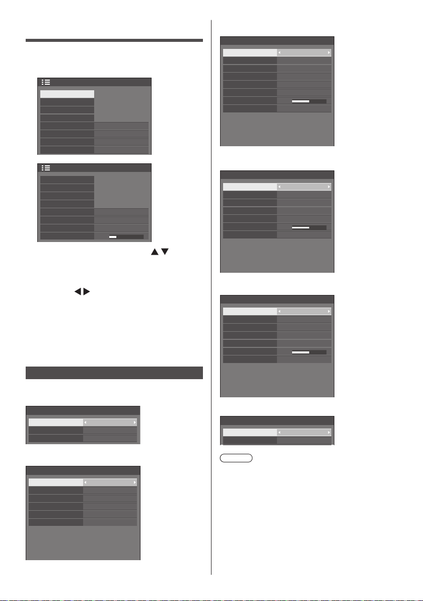
Setup menu
Press <SETUP> to display the [Setup]
1
menu.
Off
Off
Disable
Landscape
Right
60 sec
1/2
2/2
Setup
Signal
Screensaver
Input label
Power management settings
OpenPort PLATFORM standby
Wobbling
No activity power off
OSD language
Setup
Multi display settings
Set up timer
USB media player settings
Function button settings
Display orientation
OSD position
Menu display duration
Menu transparency
Select the item to set with .
2
●
Menu that cannot be adjusted is greyed out.
English(UK)
20
Adjustable menu changes depending on signal,
input and menu setting.
Set with .
3
Press <SETUP> to exit from adjust
4
mode.
■ To return to the previous screen
Press <RETURN>.
Signal
Examples of [Signal] submenu screen
When OpenPort PLATFORM is selected
Signal
Noise reduction
MPEG noise reduction
Dynamic backlight control
Auto
Off
Off
When PC is selected
Signal
Component/RGB-in select
Sync
Cinema reality
Noise reduction
MPEG noise reduction
XGA mode
Input level
Dynamic backlight control
H-freq.
V-freq.
Dot clock freq.
Signal format
RGB
Auto
Off
Auto
Off
Auto
0
Off
33.72 kHz
60.00 Hz
74.18 MHz
1125(1080)/60i
When COMPONENT / RGB is selected
Signal
Component/RGB-in select
Cinema reality
Noise reduction
MPEG noise reduction
XGA mode
Input level
Dynamic backlight control
H-freq.
V-freq.
Dot clock freq.
Signal format
Component
Off
Auto
Off
Auto
0
Off
33.72 kHz
60.00 Hz
74.18 MHz
1125(1080)/60i
When VIDEO is selected
Signal
3D Y/C filter
Colour system
Cinema reality
Noise reduction
MPEG noise reduction
Input level
Dynamic backlight control
H-freq.
V-freq.
Dot clock freq.
Signal format
Auto
Auto
0
15.73 kHz
59.94 Hz
-- MHz
NTSC
Off
Off
Off
Off
When USB is selected
Signal
Noise reduction
MPEG noise reduction
Auto
Off
When HDMI / DVI is selected
Signal
YUV/RGB-in select
Cinema reality
Noise reduction
MPEG noise reduction
Signal range
Dynamic backlight control
English
78
H-freq.
V-freq.
Dot clock freq.
Signal format
YUV
Off
Auto
Off
Full(0-255)
Off
33.72 kHz
60.00 Hz
74.18 MHz
1125(1080)/60i
Note
●
[Signal] setup menu displays a different setting
condition for each input signal.
●
Menu that cannot be adjusted is greyed out.
■ [Component/RGB-in select]
This menu is displayed at PC IN and COMPONENT/
RGB IN inputs.
Select to match the signals from the source
connected to each terminal.
Page 79

[Component] YPBPR/YCBCR signals
[RGB] RGB signals
Note
●
Set for each input terminal (COMPONENT/RGB
IN, PC IN).
■ [YUV/RGB-in select]
This menu is displayed at HDMI 1, HDMI 2 and DVI-D
IN inputs.
Select to match the signals from the source
connected to each terminal.
[YUV] YUV signals
[RGB] RGB signals
Note
●
Set for each input terminal (HDMI 1, HDMI 2,
DVI-D IN).
■ [Sync]
This menu is displayed at PC IN input.
Setting RGB/PC sync signal
[Auto]:
The H and V sync or synchronized signal is
automatically selected. When both of them have
sync signal, H and V sync will be selected.
When displaying CS signal, connect to HD input
terminal.
[on G]:
Uses a synchronized signal on the Video G
signal, which is input from the G connector.
[HV sync]:
Uses a synchronized signal on the Video HD/VD
signal, which is input from the HD/VD connector.
Setting Component sync signal
[Auto]:
The H and V sync or synchronized signal is
automatically selected. When both of them have
sync signal, H and V sync will be selected.
When displaying CS signal, connect to HD input
terminal.
[on Y]:
Uses a synchronized signal on the Video Y
signal, which is input from the Y connector.
[HV sync]:
Uses a synchronized signal on the Video HD/VD
signal, which is input from the HD/VD connector.
■ [Cinema reality]
Faithfully reproduces videos shot with cinema films.
Set this to [Off] normally.
Note
●
In [ENGLISH(US)] OSD language, [Cinema reality]
is displayed as [3:2 PULLDOWN].
●
If [Cinema reality] is set to [On], videos including
movies shot at 24 frames per second are
reproduced more naturally.
●
If the video is unnatural with [On] set, set it to [Off].
■ [Noise reduction]
Reduces picture noise.
[Off]:
Disables Noise Reduction.
[Min], [Mid], [Max]:
Sets strength of Noise Reduction.
[Auto]:
Noise reduction will be automatically selected from
[Min], [Mid] or [Max].
■ [MPEG noise reduction]
Reduces block noise and mosquito noise on MPEG
videos.
[Off]:
Disables Noise Reduction.
[Min], [Mid], [Max]:
Sets strength of Noise Reduction.
■ [XGA mode]
This menu is displayed at PC IN and COMPONENT/
RGB IN inputs.
This unit supports XGA signals (1024 × 768, 1280 ×
768, 1366 × 768) having different aspect ratios and
sampling rates.
[Auto]:
Automatically detects the signal.
Switch the setting to suit the input signal for better
display depends on the angle of view or display
resolution condition.
Note
●
After making this setting, be sure to make each
adjustment (such as [Auto setup]) on the [Position]
menu as necessary. (see page 68)
■ [Signal range]
This menu is displayed at HDMI1, HDMI2 and DVI-D
IN inputs. Switches the dynamic range to match the
signals from the source connected to each terminal.
[Video(16-235)]:
If the input signal is the video range
Example: HDMI terminal output for DVD player
[Full(0-255)]:
If the input signal is full range
Example: HDMI terminal output for personal
computer
[Auto]:
Switches the dynamic range automatically between
[Video(16-235)] and [Full(0-255)] according to the
input signal.
Note
●
[Auto] can be selected when the HDMI signal input.
English
79
Page 80
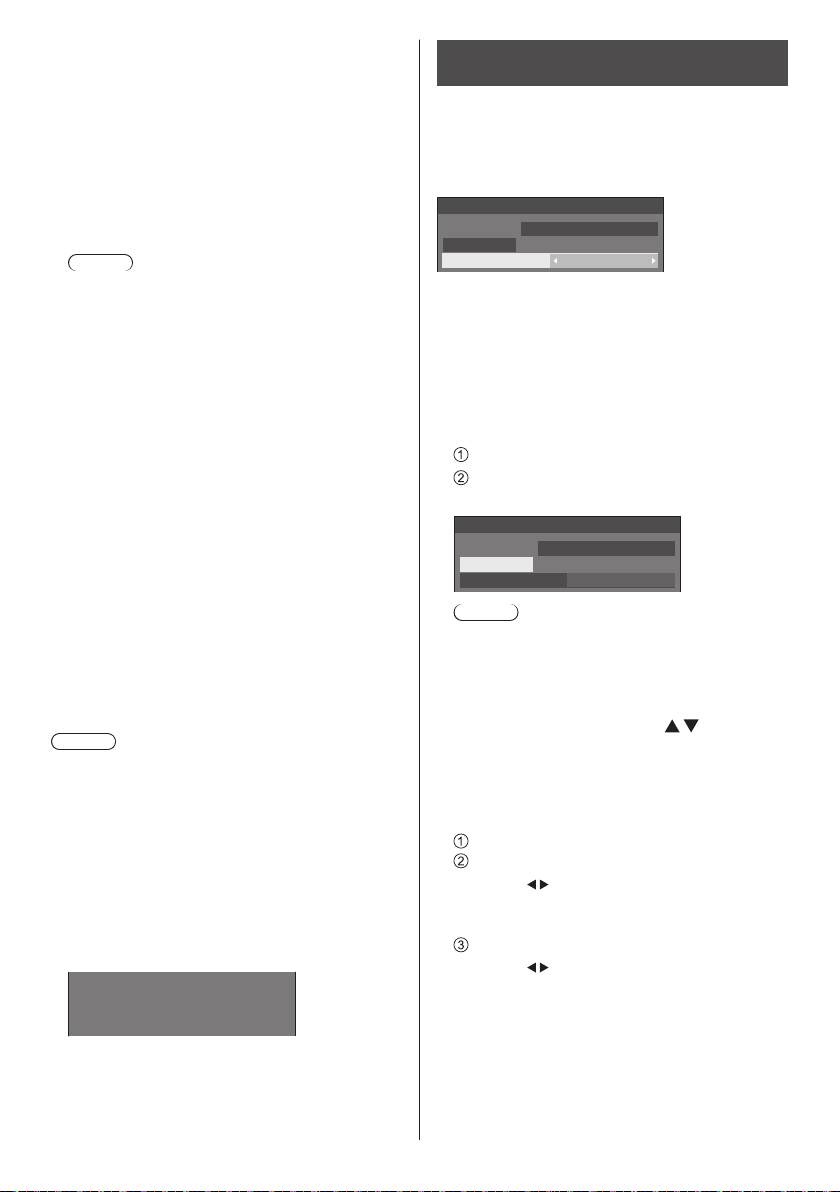
■ [Input level]
This menu is displayed at PC IN, COMPONENT/RGB
IN and VIDEO IN inputs.
Adjustment of parts which are extremely bright and
hard to see.
- 16 to + 16:
(Level low) - (Level high)
■ [3D Y/C filter]
Set this if the video looks unnatural at VIDEO IN
input. Set this to [On] normally.
Note
●
Depending on the signalling system, this setting
may be less effective or may not be effective at all.
■ [Colour system]
Sets the colour system according to the signal
method at VIDEO IN input. Set this to [Auto] normally.
This automatically detects the input signal format.
[Auto], [PAL ], [SECAM], [NTSC], [NTSC 4.43], [PAL
M], [PAL N]:
Set this to [Auto] when viewing PAL-60 videos.
When images are unstable
When the system is set to [Auto], images become
unstable in rare case under the condition that the
input signals are at low level or have many noises.
In this case, set the system so it conforms with the
input signal format.
■ [Dynamic backlight control]
Improves picture contrast and alleviates whiteness
by controlling the back light when signals with the low
average brightness level (APL) are input.
[On]:
The function is enabled.
[Off]:
The function is disabled.
Note
●
When this function is operating, the on-screen
brightness becomes lower.
●
If the [Dynamic backlight control] setting is different
for each input, the on-screen brightness may change
by switching input.
●
Depending on the displayed image, the screen may
flicker. If this annoys you, set [Dynamic backlight
control] to [Off].
■ Input signal display
Displays the frequency and the type of the current
input signal.
33.72 kHz
H-freq.
60.00 Hz
V-freq.
Dot clock freq.
Signal format
Display range:
Horizontal (15 kHz - 135 kHz)
Vertical (24 Hz - 120 Hz)
The dot clock frequency is displayed when Digital and
PC signal are input.
English
80
74.18 MHz
1125(1080)/60i
Screensaver (For preventing image retention)
Do not display a still picture, especially in 4:3 mode, for
any length of time.
If the display must remain on, a Screensaver should be
used.
[Screensaver] - submenu screen
Screensaver
10:00
Start
Mode Off
2016/01/01
FRIDAY
■ Screensaver settings
Screensaver operation
When the Screensaver is operating, the following 5
patterns are displayed full screen for 5 seconds each,
and it will be repeated.
Black → Dark grey → Grey → Light grey → White →
Light grey → Grey → Dark grey
To start Screensaver now
Select [On] in [Mode].
Select [Start] and press <ENTER>.
●
The Screensaver will be activated.
Screensaver
10:00
Start
Mode On
2016/01/01
Note
●
If the following buttons are pressed while the
screen saver is operating, the screen saver is
cancelled.
Remote control: <RETURN>
Main unit: <MENU (Unit)> <INPUT (Unit)>
<+ (Unit)> <- (Unit)>
<ENTER (Unit)>
●
When the display is turned off, the Screensaver will
be deactivated.
To set interval of Screensaver
Select [Interval] in [Mode].
Set [Periodic time].
●
●
to change the time by 15 minutes.
Press
In [ENGLISH(US)] OSD language, [Periodic
time] is displayed as [SHOW DURATION].
Set [Operating time].
●
once to change the time by 1 minute.
Press
Keep pressing down to change the time by 15
minutes.
●
In [ENGLISH(US)] OSD language, [Operating
time] is displayed as [SAVER DURATION].
FRIDAY
Page 81
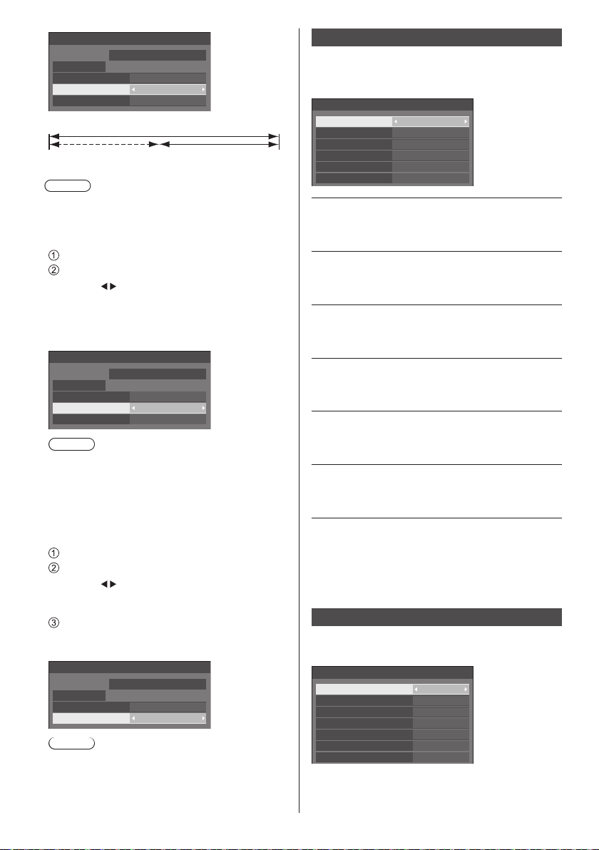
Screensaver
Start
Mode Interval
Periodic time
Operating time
2016/01/01 10:00
FRIDAY
0:00
0:00
Periodic time
Deactivated. Operating time
Note
●
It is not possible to set the duration of [Operating
time] longer than that of [Periodic time].
To set start and finish time of Screensaver
Select [Time designation] in [Mode].
Set [Start time] and [Finish time].
●
once to change the time by 1 minute.
Press
Keep pressing down to change the time by 15
minutes.
●
In [ENGLISH(US)] OSD language, [Time
designation] is displayed as [TIME OF DAY].
Screensaver
10:00
Start
Mode Time designation
Start time
Finish time
2016/01/01
FRIDAY
0:00
0:00
Note
●
Please set [Date & time] in OpenPort PLATFORM
before setting [Start time] and [Finish time]. (see
page 59)
●
This can be set only when the date is 2016/01/01
and after.
To turn the power off after Screensaver
Select [Standby after SCR saver] in [Mode].
Set [Screensaver duration].
●
once to change the time by 1 minute.
Press
Keep pressing down to change the time by 15
minutes.
Select [Start] and press <ENTER>.
●
Screensaver will be activated and the power will
be turned off (standby) at the time set.
Screensaver
10:00
Start
Mode
Screensaver duration 0:00
2016/01/01
FRIDAY
Standby after SCR saver
Note
●
[Screensaver duration] can be set from 0:00 to
23:59.
When this is set to [0:00], [Standby after SCR
saver] will not be activated.
Input label
This function can change the label of the Input signal to
be displayed.
[Input label] - submenu screen
Input label
HDMI1
HDMI2
DVI-D
PC
COMPONENT COMPONENT
VIDEO
HDMI1
HDMI2
DVI-D
PC
VIDEO
[HDMI1] [HDMI1] / [DVD1] / [DVD2] /
[DVD3] / [Blu-ray1] / [Blu-ray2] /
[Blu-ray3] / [CATV] / [VCR] /
[STB] / (Skip)
[HDMI2] [HDMI2] / [DVD1] / [DVD2] /
[DVD3] / [Blu-ray1] / [Blu-ray2] /
[Blu-ray3] / [CATV] / [VCR] /
[STB] / (Skip)
[DVI-D] [DVI-D] / [DVD1] / [DVD2] /
[DVD3] / [Blu-ray1] / [Blu-ray2] /
[Blu-ray3] / [CATV] / [VCR] /
[STB] / (Skip)
[PC] [PC] / [DVD1] / [DVD2] /
[DVD3] / [Blu-ray1] / [Blu-ray2] /
[Blu-ray3] / [CATV] / [VCR] /
[STB] / (Skip)
[COMPONENT]*[COMPONENT] / [DVD1] /
[DVD2] / [DVD3] / [Blu-ray1] /
[Blu-ray2] / [Blu-ray3] / [CATV] /
[VCR] / [STB] / (Skip)
[VIDEO] [VIDEO] / [DVD1] / [DVD2] /
[DVD3] / [Blu-ray1] / [Blu-ray2] /
[Blu-ray3] / [CATV] / [VCR] /
[STB] / (Skip)
(Skip): When <INPUT> is pressed, the input will be
skipped.
: [COMPONENT] may be displayed as [RGB]
*
depending on the settings of [Component/RGB-in
select]. (see page 78)
Power management settings
Set each item to reduce power consumption.
[Power management settings] - submenu screen
Power management settings
Power management mode
No signal power off
HDMI1 power management
HDMI2 power management
DVI-D power management
PC power management
Power save
Custom
Disable
Off
Off
Off
Off
Off
English
81
Page 82

■ [Power management mode]: [On]
The following fixed values are set to the menu of
power consumption reduction. Individual setting is not
available.
[No signal power off]: [Enable]
[HDMI1 power management]: [On]
[HDMI2 power management]: [On]
[DVI-D power management]: [On]
[PC power management]: [On]
[Power save]: [On]
■ [Power management mode]: [Custom]
The menu of the power consumption reduction is
individually set. This setting is enabled when [Power
management mode] is set to [Custom].
[No signal power off]
When this is set to [Enable], the power supply of the
unit goes off automatically (standby) when there is no
operation or sync signal for about 10 minutes.
Note
●
With the USB input, the unit determines no signal is
present when the USB memory is not connected to
the USB terminal.
●
The OpenPort PLATFORM input is not a target of the
“no signal” detection.
[HDMI1 power management]
[HDMI2 power management]
When this function is set to [On], it operates under
the following conditions to turn the power on or off
automatically.
When no pictures (sync signal) are detected for
60 seconds or so at HDMI1 or HDMI2 input:
Power is turned off (sleep); the power indicator
lights up orange.
When pictures (sync signal) are subsequently
detected:
Power is turned on; the power indicator lights up
green.
Note
●
For TH-55AF1U, TH-49AF1U and TH-42AF1U,
when the power is turned off, the OpenPort
PLATFORM system is shutdown once, and then
restarted. During that time (approx. 60 seconds),
the power on processing by detecting pictures
(sync signal) is not accepted.
[DVI-D power management]
When this function is set to [On], it operates under
the following conditions to turn the power on or off
automatically.
When no pictures (sync signal) are detected for
60 seconds or so at DVI-D input:
Power is turned off (sleep); the power indicator
lights up orange.
When pictures (sync signal) are subsequently
detected:
Power is turned on; the power indicator lights up
green.
Note
●
For TH-55AF1U, TH-49AF1U and TH-42AF1U,
when the power is turned off, the OpenPort
PLATFORM system is shutdown once, and then
restarted. During that time (approx. 60 seconds),
the power on processing by detecting pictures
(sync signal) is not accepted.
[PC power management] (DPMS function)
When this function is set to [On], it operates under
the following conditions to turn the power on or off
automatically.
When no pictures (HD/VD sync signals) are
detected for 60 seconds or so at PC input:
Power is turned off (sleep); the power indicator
lights up orange.
When pictures (HD/VD sync signals) are
subsequently detected:
Power is turned on; the power indicator lights up
green.
Note
●
This function is effective when [Sync] in [Signal] is
set to [Auto] or [HV sync] and [Component/RGB-in
select] are set to [RGB]. (see page 78)
●
For TH-55AF1U, TH-49AF1U and TH-42AF1U,
when the power is turned off, the OpenPort
PLATFORM system is shutdown once, and then
restarted. During that time (approx. 60 seconds),
the power on processing by detecting pictures (HD/
VD sync signals) is not accepted.
[Power save]
This function adjusts the brightness of the backlight to
reduce power consumption.
[Off]:
This function does not operate.
[On]:
Backlight brightness is reduced.
Note
●
If [Input search] is set to items other than [Off], the
[Input search] function is prioritised. (The “Power
management” function does not operate for each
terminal.) (For details of [Input search] function,
see page 88.)
●
If [Failover/Failback] - [Input change mode] is set
to items other than [Off], the [Failover/Failback]
function is prioritised. (The “Power management”
function does not operate for each terminal.) (For
details of [Failover/Failback] function, see page
89.)
82
English
Page 83

OpenPort PLATFORM standby
This switches the operation status of the OpenPort
PLATFORM system in standby mode.
For TH-55AF1W, TH-49AF1W and TH-42AF1W
[Off]:
When the power is turned off with remote control,
etc.
Shuts down the OpenPort PLATFORM system.
When it is in standby condition (Power Indicator:
Red)
It is possible to startup with remote control or RS-232C,
but it is not possible to startup with timer setting, wired
LAN or wireless LAN.
[On] (Factory default):
When the power is turned off with remote control,
etc.
Does not shut down the OpenPort PLATFORM system.
When it is in standby condition (Power Indicator:
Orange)
It is possible to startup with timer setting, wired LAN
and wireless LAN.
For TH-55AF1U, TH-49AF1U and TH-42AF1U
[Off] (Factory default):
When the power is turned off with remote control, etc.
Shuts down the OpenPort PLATFORM system.
When it is in standby condition (Power Indicator:
Red)
It is possible to startup with remote control or RS-232C,
but it is not possible to startup with timer setting, wired
LAN or wireless LAN.
[On]:
When the power is turned off with RS-232C control
or LAN control
Does not shut down the OpenPort PLATFORM system.
When the power is turned off with something other
than RS-232C control or LAN control
Shuts down the OpenPort PLATFORM system once,
and then restarts the system. During that time (approx.
60 seconds), the power on processing is not accepted.
When it is in standby condition (Power Indicator:
Orange)
It is possible to startup with timer setting, wired LAN
and wireless LAN.
Wobbling
Automatically shifts the display image (therefore
unnoticeable to the eye) to prevent image retention of
sharper contour of image.
Setting this to [On] moves the screen position at certain
intervals and displays the images.
Note
●
If [Multi display setting] is set to [On], this function
does not operate. (see page 84)
●
When this function is operating, part of the screen
may appear to be missing.
No activity power off
When this function is set to [Enable], the power is turned
off (standby) automatically when there is no operation of
the Display for 4 hours.
Starting from 3 minutes before the turn off, the
remaining time will be displayed.
Press any key to abort.
No activity power off
When the power is turned off due to this function, a
message [Last turn off due to ‘No activity power off’.]
is displayed next time the power is turned on.
Note
●
While the screensaver is running, this function is
disabled.
●
This function is not activated with OpenPort
PLATFORM input.
3 min
OSD language
Select your preferred language.
Selectable languages
English(UK)
Deutsch
Français
Italiano
Español
ENGLISH(US)
中文
日本語
Русский : Russian
Note
●
It is also possible to set language in [Language &
input] in OpenPort PLATFORM. (see page 58)
●
The display may be greyed out and setting cannot
be made in some conditions, such as when the
OpenPort PLATFORM system is starting up.
: Chinese
: Japanese
English
83
Page 84

Multi display settings
....
1 to 10 displays can be aligned in horizontal direction
and vertical direction respectively, and those displays
are regarded as one group. The enlarged image is
shown on the combined display.
[Multi display settings]- submenu screen
Multi display settings
Multi display setting
Horizontal scale
Vertical scale
Bezel H adjustment
Bezel V adjustment
Location
Note
●
The settings are memorised separately for each
input terminal.
●
When the multi display is set to [Off], adjust to the
same angle of view for [Position] (see page 68).
Then, set the multi display to [On]. Again, make
fine adjustment of the angle of view for [Position].
●
The [Position] menu can be adjusted in the multi
display status.
Off
2
2
0
0
A1
■ [Multi display setting]
[Off]:
The display is not divided when enlarged.
[On]:
The display is divided when enlarged.
When [On] is set, the display aspect is [16:9].
■ [Horizontal scale]
Set the horizontal scale in the multi display.
1 to 10 (1 to 2 for USB input)
■ [Vertical scale]
Set the vertical scale in the multi display.
1 to 10 (1 to 2 for USB input)
Example:
[Horizontal scale] [5] and [Vertical scale] [5] is set in
the multi display
■ [Bezel H adjustment], [Bezel V adjustment]
Adjust the area of image hidden in the joint
horizontally and vertically respectively.
0 to 100
Display example
Setting value: 0
Displays the entire image including the joint area.
(Suitable when displaying character information
on PC.)
Setting value: 100
Does not display the image of the joint area.
(Suitable when displaying motion pictures.)
■ [Location]
Assign the multi display position.
Example:
[Horizontal scale] [10], [Vertical scale] [10]
A1 A2
B1 B2
.... ....
I1 I2 I9
J1 J2 J9
Select from A1 to J10.
●
The displayed content for setting changes
according to the settings for the [Horizontal scale]
and [Vertical scale].
●
By setting [Multi display setting] to [Off], it is
possible to check the location on the screen while
the setting menu is displayed.
....
....
....
....
A9
B9
....
A10
B10
....
I10
J10
84
English
Page 85

Set up timer
Sets the program to turn the power on/off or switch video
inputs at the specified time. Up to 20 programmes can
be set.
Note
●
Set [Date & time] in OpenPort PLATFORM before
setting [Set up timer]. (see page 59)
●
This can be set only when the date is 2016/01/01 and
after.
●
When multiple programs are set at the same time,
the program with the smallest program number is
enabled.
●
To set programme to turn the power on/off, set
[OpenPort PLATFORM standby] to [On]. (see page
83)
[Set up timer] - submenu screen
Setting Example
Program 1, Every Monday, 12:00,
Power On, Input: HDMI1
Set up timer
10:00
Program
Timer function
Day
Power mode
Time
Input
Set the program number.
1
To execute the program, set to [On].
2
The program is disabled when [Off] is set.
Set the day.
3
2016/01/01
The program is executed every day when
[Everyday] is set.
Set the power On/Off.
4
Set the time.
5
Pressing
once changes time 1 minute.
Pressing continuously changes time by 15
minutes.
Set the input.
6
FRIDAY
1
On
MONDAY
Power on
12:00
HDMI1
1
2
3
4
5
6
USB media player settings
Set for USB media player function.
[USB media player settings] - submenu screen
USB media player settings
USB media player
Resume play
Scenario file check
No scenario file
Slide show duration
Enable
On
10 sec
■ [USB media player]
Set to enable or disable the USB media player
function.
■ [Resume play]
Set resume play off/on.
■ [Scenario file check]
Execute the contents check of the USB memory
which is connected to the USB terminal. If any error
is detected, the error code and file name will be
displayed.
For details of the error codes, refer to “USB memory
contents check”. (see page 105)
Select [Scenario file check] with
and press
<ENTER>.
Scenario file check
Available
■ [Slide show duration]
Select the displaying duration for still images.
[10 sec] to [600 sec]
Function button settings
Assigns specific functions to the numeric buttons (<1>
to <6>). The buttons can be used as shortcut keys by
assigning frequently used operations.
Switch [Function group] with .
1
[Function button settings] - submenu screen
Function button settings
Function group
Function button 1
Function button 2
Function button 3
Function button 4
Function button 5
Function button 6
Function button guide
Input
HDMI1
HDMI2
DVI-D
PC
COMPONENT
OpenPort PLATFORM / KEYBOARD
On
Input
↓
Memory load
↓
Shortcut
English
85
Page 86

Select the numeric button with
2
and set the function to assign with
.
■ Functions assignable to the numeric
buttons
[Input] (Direct input select)
Input can be selected with single-touch operation.
[OpenPort PLATFORM] / [HDMI1] / [HDMI2] /
[DVI-D] / [PC] / [COMPONENT]* / [VIDEO] /
[USB]
: [COMPONENT] may be displayed as [RGB]
*
depending on the settings of [Component/RGBin select]. (see page 78)
●
Button <6> already has functions to select the
OpenPort PLATFORM input with single-touch
operation and display the software keyboard
(see page 43) during the OpenPort PLATFORM
input. This setting cannot be changed.
[Memory load]
Memory can be loaded with single-touch operation.
Memory load (see page 75)
[MEMORY 1] to [MEMORY 5]
●
[MEMORY 1] to [MEMORY 5] load functions are
already assigned to <1> to <5> respectively.
These settings cannot be changed.
[KEYBOARD]
●
Button <6> already has the function to display
the software keyboard (see page 43) during
the OpenPort PLATFORM input. No specific
functions are assigned for inputs other than the
OpenPort PLATFORM input. This setting cannot
be changed.
[Shortcut]
[Signal], [Screensaver], [Set up timer], [Power
management settings], [Multi display settings]
●
Pressing the numeric button displays the menu
screen. Pressing the button again exits the
menu screen.
[AV mute]
●
Pressing the numeric button mutes the audio
and pictures.
To cancel, press any button on the remote
control except the <Standby (ON/OFF) button>.
[Digital zoom]
●
Switches to [Digital zoom] mode by pressing
numeric buttons. (see page 65)
[KEYBOARD]
●
Button <6> already has the function to display
the software keyboard (see page 43) during
the OpenPort PLATFORM input. No specific
functions are assigned for inputs other than the
OpenPort PLATFORM input. This setting cannot
be changed.
Shipping condition
The following functions are assigned to the numeric
buttons as factory default.
[Input]
1 HDMI1 MEMORY 1 [Signal]
2 HDMI2 MEMORY 2 [Screensaver]
3 DVI-D MEMORY 3 [Set up timer]
4 PC MEMORY 4
5
COMPONENT
OpenPort
6
PLATFORM /
KEYBOARD
[Memory
load]
MEMORY 5 [AV mute]
---- /
KEYBOARD
■ [Function button guide]
Sets the function display when numeric buttons are
pressed. Set this for each function group.
[On]:
Displays the function list for the numeric buttons.
[Off]:
Does not display the function list. Operation starts
when numeric buttons are pressed.
Note
●
When <FUNCTION> is pressed, [Function button
guide] will be displayed regardless of the [On] / [Off]
settings.
■ To use shortcut (numeric buttons)
Press <FUNCTION> or <1> - <6>.
1
[Function button guide] will be displayed.
[Function button guide]: When [Off] is set, pressing
the numeric button starts operation.
Example: Input
Input
HDMI 1
1.
HDMI 2
2.
DVI-D
3.
PC
4.
COMPONENT
5.
OpenPort PLATFORM
6.
When using OpenPort PLATFORM input, number 6
will be [KEYBOARD].
[Shortcut]
[Power
management
settings]
---- /
KEYBOARD
86
English
Page 87
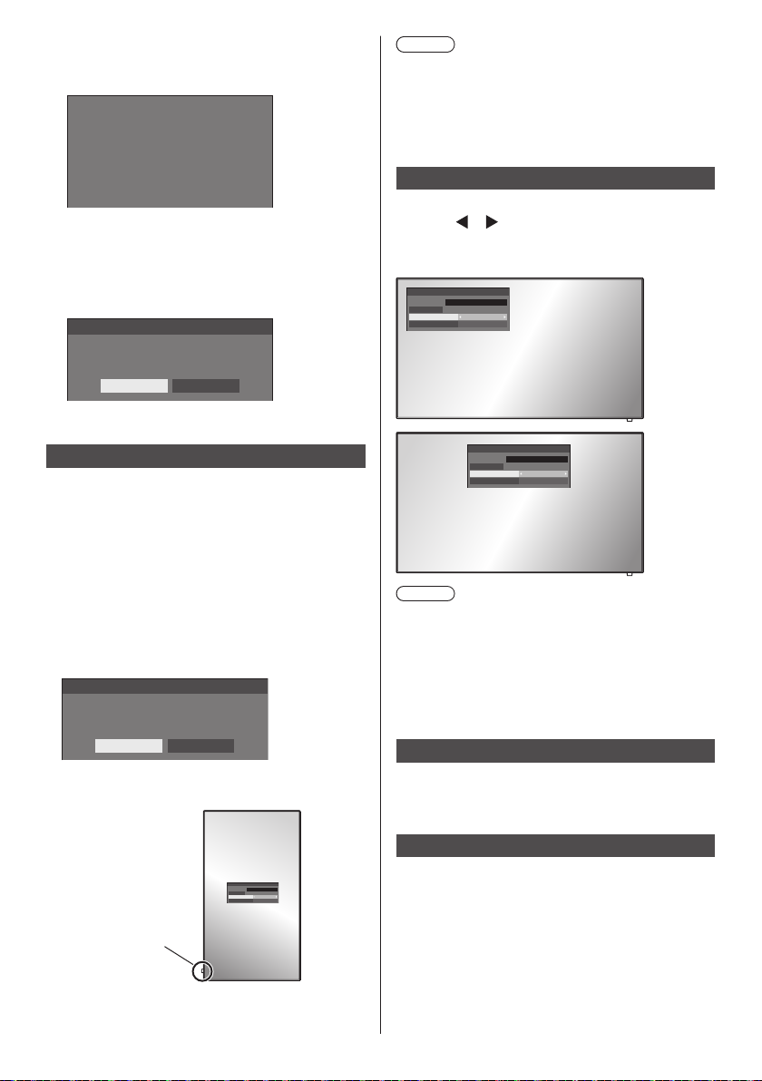
Press <FUNCTION> to switch function
2
group.
Example: Memory load
Memory load
MEMORY 1
1.
MEMORY 2
2.
MEMORY 3
3.
MEMORY 4
4.
MEMORY 5
5.
----
6.
When using OpenPort PLATFORM input, number 6
will be [KEYBOARD].
Press <1> - <6>.
3
The function for the pressed button starts to operate.
Example: When <2> is pressed.
Memory load
Load from “MEMORY 2”
Ok Cancel
Display orientation
Sets the on-screen display orientation in the portrait
setting.
[Landscape]:
On-screen display angle is for horizontal
installation.
[Portrait]:
The on-screen display rotates anticlockwise by 90
degrees for easy view in the portrait setting.
When the setting is changed, a confirmation message to
restart OpenPort PLATFORM is displayed.
Display orientation
Do you want to reboot OpenPort PLATFORM?
Yes No
Select [Yes ] with ◀ ▶ and press <ENTER> to restart.
(Startup of OpenPort PLATFORM: see page 40)
Note
●
In the portrait setting, the power indicator shall come
to the downside.
●
The display may be greyed out and setting cannot
be made in some conditions, such as when the
OpenPort PLATFORM system is starting up.
OSD position
Sets the display position of the on-screen menu.
Each time
or is pressed, the display position of the
on-screen menu changes.
Display example:
18:00
Left
18:00
Centre
Note
●
Display position settings vary depending on the
setting of [Display orientation].
[Display orientation]: When it is set to
[Landscape]
[Left] / [Centre] / [Right]
[Display orientation]: When it is set to [Portrait]
[Upper] / [Centre] / [Lower]
Menu display duration
Sets the display duration time for the on-screen menu.
[5 sec] to [180 sec]
Power indicator
Menu transparency
Sets the transparency rate of the on-screen display
18:00
background.
0 to 100
English
87
Page 88
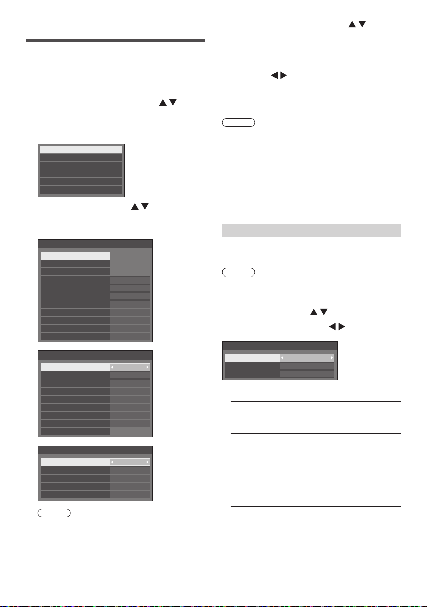
Options Adjustments
This unit offers special functions conveniently used
according to the installation location and application.
Press <SETUP>.
1
[Setup] menu screen will be displayed.
Select [OSD language] with
2
and press <ENTER> for more than 3
seconds.
Following screen will be displayed.
Options
Display serial number
Software licenses
USB data cloning
Shipping
OpenPort PLATFORM Shutdown
Select [Options] with and press
3
<ENTER>.
[Options] menu screen will be displayed.
On
Off
Off
0
Off
0
Off
Off
Off
Off
Enable
Last memory
Off
0
Off
Off
---
Off
Off
On
On
1/3
2/3
3/3
Options
Input search
Failover/Failback
Audio input select
Onscreen display
Initial input
Initial VOL level
Maximum VOL level
Input lock
Button lock
Controller user level
PC auto setting
Options
Off-timer function
Initial startup
Startup logo
Display ID
Controller ID function
Serial ID function
Serial response(ID all) Off
Serial daisy chain position
Information timing
Options
Power on screen delay
Clock display
Power on message(No activity power off)
Power on message(Power management)
POWER button lock Off
Note
●
[POWER button lock] function is only for TH55AF1U, TH-49AF1U and TH-42AF1U.
Select the item to set with .
4
For [Input search], [Failover/Failback], [Audio input
select] and [Information timing], the submenu screen
will be displayed when you press <ENTER>.
(see page 89, 92, 95)
Set with .
5
Press <SETUP> to exit from [Options]
6
menu.
Note
●
The remote control is necessary to display the
[Options] menu. The control panel buttons on the
main unit cannot be used to display the menu.
●
Press <RETURN> to return to the previous menu.
●
The serial number of this device is displayed when
[Display serial number] is selected in step 3.
●
The software License is displayed when [Software
licenses] is selected in step 3.
Input search
When a signal is not detected, another input with a
signal is automatically selected.
Note
●
The OpenPort PLATFORM input is not a target of the
“no signal” detection. It is excluded from this function.
Select the item with .
Select the set point with
Input search
Input search
1st search input
2nd search input
[Input search]
[Off]:
When there is no signal, the input is not switched
automatically.
[All inputs]:
Searches all inputs except [OpenPort PLATFORM],
and switches to an input with a signal.
Input search is executed in the following order.
(Example) When the current input is [HDMI1]
[HDMI2]→[DVI-D]→[PC]→[COMPONENT]*→
[VIDEO]→[USB]→[HDMI1]
Custom
(None)
(None)
.
88
English
Page 89
Note
●
The inputs set to [(Skip)] in [Input label] (see page
81) are skipped when searching.
●
When Y/G/VIDEO terminal is used as VIDEO
input, set [COMPONENT]* to [(Skip)].
: [COMPONENT] may be displayed as [RGB]
*
depending on the settings of [Component/RGB-in
select]. (see page 78)
[Custom]:
Repeatedly searches [Current input], [1st search
input] and [2nd search input] in order, and switches
to an input with a signal.
PC
Searching...
[Searching...] is displayed during the input search.
[1st search input], [2nd search input]
Set the input to search when [Custom] is selected.
[HDMI1] / [HDMI2] / [DVI-D] / [PC] /
[COMPONENT]* / [VIDEO] / [USB] / (None)
: [COMPONENT] may be displayed as [RGB]
*
depending on the settings of [Component/RGB-in
select]. (see page 78)
Note
●
With the USB input, the unit determines no signal
is present when the USB memory is not connected
to the USB terminal.
●
This menu will be greyed out and cannot be set
under the following conditions.
[Input lock] is not set to [Off]. (see page 93)
•
[Failover/Failback] - [Input change mode] is not
•
set to [Off]. (see page 89)
●
If the input is changed by this function, the last
input is selected when the power is turned on next
time.
If you wish to retain the original input when the
power is turned on, set [Initial input] to the original
input. (see page 92)
Failover/Failback
Automatically switches to the backup input video if an
interruption of video occurs.
Select the item with .
1
Select the set point with
[Input change mode]
[Off]:
Disables the Backup Input function.
.
Failover/Failback
Input change mode Off
[Quick]:
Promptly switches to the backup input if an
interruption of video occurs.
The backup video signal needs to be in the same
format as the (main) input in use for viewing.
Upon switching to the backup input, the video and
audio adjustment values for the (main) input used
for viewing will be inherited.
Failover/Failback
Input change mode
Primary backup input
Secondary backup input
Auto switch back mode
Changing mode High speed
Backup input change
Main input
Current input
Quick
HDMI1
DVI-D
Disable
Active
HDMI2
Main input
[Normal]:
Switches to the backup input if an interruption of
video occurs.
The backup video signal does not need to be in the
same format as the (main) input in use for viewing.
Upon switching to the backup input, the video and
audio adjustment values for the backup input will
be used.
■ [Input change mode]: [Quick]
Promptly switches to the backup input if an
interruption of video occurs, and enables switching
between digital (HDMI1 / HDMI2 / DVI-D) inputs.
Note
●
The backup video signal needs to be in the same
format as the (main) input in use for viewing.
●
Upon switching to the backup input, the video and
audio adjustment values for the (main) input used for
viewing will be inherited.
●
When switching from [Main input (except for
OpenPort PLATFORM)] to [Backup Input OpenPort
PLATFORM], the following functions take over
operation as main input.
[No activity power off], main unit button operation
●
This function will start operating once a video signal is
detected by both the input in use for viewing and the
backup input and the [Backup input change] item is
displayed as [Active].
[Primary backup input]
Sets the first priority backup input.
(None) / [OpenPort PLATFORM] / [HDMI1] /
[HDMI2] / [DVI-D]
The input that is of the same type as the one in use
for viewing will be greyed out.
English
89
Page 90

[Secondary backup input]
Sets the second priority backup input.
(None) / [OpenPort PLATFORM] / [HDMI1] /
[HDMI2] / [DVI-D]
The input that is of the same type as the one in use
for viewing will be greyed out.
[Auto switch back mode]
Sets whether or not to automatically return to the
former (main) input when the former input video
initially viewed is restored while viewing the video
of the backup input enabled by the operation of the
Backup Input function.
[Disable]:
Unreturned
[Enable]:
Returned
[Changing mode]
Select speed of input switching.
[High speed]:
If switching between the same signal formats, it is
possible to switch within 1 second.
If switching between the different signal formats,
picture noise is caused.
[Normal speed]:
If switching between the same signal formats, it is
possible to switch within 2 seconds.
If switching between the different signal formats, it
takes 3 to 4 seconds to switch but picture noise is
not caused.
●
The OpenPort PLATFORM input is treated as 1
125(1 080)/60p signal format equivalent.
[Backup input change]
Displays whether or not operating conditions for the
Backup Input function are met.
[Inactive]:
Indicates that the conditions are not met, and
inactivates the Backup Input function.
[Active]:
Indicates that the conditions are met, and activates
the Backup Input function.
Setting conditions
The following table describes restrictions (available
combinations) on each setting item.
Backup
OpenPort
PLATFORM
HDMI1
HDMI2
PC
*
COMPONENT
USB
VIDEO
DVI-D
OpenPort
PLATFORM
× × ×
HDMI1
○ × ×
Main
HDMI2
DVI-D
PC
COMPONENT
*
× × ×
VIDEO
USB × × ×
○:SelectableforbothPrimaryandSecondary.
×: Not selectable for neither Primary nor Secondary.
: [COMPONENT] may be displayed as [RGB]
*
depending on the settings of [Component/RGB-in
select]. (see page 78)
Recall display
Pressing <RECALL> displays any of the followings.
●
When the main input is being used for viewing and
the operating conditions for the Backup Input function
are met.
HDMI1
16:9
Main input
Backup OK
●
When the backup input, enabled by the operation of
the Backup Input function, is being used for viewing.
HDMI1
16:9
Backup Input
DVI
When the conditions for the Backup Input function
are met, the following screen is displayed.
[Main input]
Displays the (main) input initially used for viewing.
[Current input]
Displays whether the input currently in use for viewing
is the (main) input initially used for viewing or the
backup one.
English
90
Main input
Backup OK
Page 91
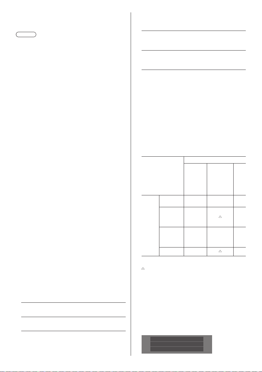
■ [Input change mode]: [Normal]
Switches to the backup input if an interruption of
video occurs.
Note
●
When an analogue (PC, COMPONENT or VIDEO)
input is being used for viewing, you cannot set an
analogue (PC, COMPONENT or VIDEO) input as a
backup input.
●
Any analogue (PC, COMPONENT or VIDEO)
input cannot be set as [Primary backup input] or
[Secondary backup input].
●
This function will start operating once a video signal is
detected by both the input in use for viewing and the
backup input and the [Backup input change] item is
displayed as [Active].
[Primary backup input]
Sets the first priority backup input.
(None) / [OpenPort PLATFORM] / [HDMI1] /
[HDMI2] / [DVI-D] / [PC] / [COMPONENT]* /
[VIDEO] / [USB]
The input that is of the same type as the one in use
for viewing will be greyed out.
When an analogue (PC, COMPONENT or VIDEO)
input is being used for viewing, you cannot set an
analogue (PC, COMPONENT or VIDEO) input as a
backup input.
Any analogue (PC, COMPONENT or VIDEO)
input cannot be set as [Primary backup input] or
[Secondary backup input].
[Secondary backup input]
Sets the second priority backup input.
(None) / [OpenPort PLATFORM] / [HDMI1] /
[HDMI2] / [DVI-D] / [PC] / [COMPONENT]* /
[VIDEO] / [USB]
The input that is of the same type as the one in use
for viewing will be greyed out.
When an analogue (PC, COMPONENT or VIDEO)
input is being used for viewing, you cannot set an
analogue (PC, COMPONENT or VIDEO) input as a
backup input.
Any analogue (PC, COMPONENT or VIDEO)
input cannot be set as [Primary backup input] or
[Secondary backup input].
[Auto switch back mode]
Sets whether or not to automatically return to the
former (main) input when the former input video
initially viewed is restored while viewing the video
of the backup input enabled by the operation of the
Backup Input function.
[Disable]:
Unreturned
[Enable]:
Returned
[Backup input change]
Displays whether or not operating conditions for the
Backup Input function are met.
[Inactive]:
Indicates that the conditions are not met, and
inactivates the Backup Input function.
[Active]:
Indicates that the conditions are met, and activates
the Backup Input function.
[Main input]
Displays the (main) input initially used for viewing.
[Current input]
Displays whether the input currently in use for viewing
is the (main) input initially used for viewing or the
backup one.
: [COMPONENT] may be displayed as [RGB]
*
depending on the settings of [Component/RGB-in
select]. (see page 78)
Setting conditions
The following table describes restrictions (available
combinations) on each setting item.
Backup
OpenPort
PLATFORM
HDMI1
HDMI2
DVI-D
OpenPort
PLATFORM
HDMI1
HDMI2
DVI-D
Main
PC
COMPONENT
VIDEO
USB ○
○:SelectableforbothPrimaryandSecondary.
: Selectable for either Primary or Secondary.
×: Not selectable for neither Primary nor Secondary.
: [COMPONENT] may be displayed as [RGB]
*
depending on the settings of [Component/RGB-in
select]. (see page 78)
Recall display
Pressing <RECALL> displays any of the followings.
●
When the main input is being used for viewing and
the operating conditions for the Backup Input function
are met.
*
HDMI1
16:9
Backup mode OK
PC
*
COMPONENT
VIDEO
× × ×
○ ○
○ × ○
USB
×
English
91
Page 92

●
When the backup input, enabled by the operation of
the Backup Input function, is being used for viewing.
HDMI1
16:9
Primary backup input
When the conditions for the Backup Input function
are met, the following screen is displayed.
Backup mode OK
Note
●
This menu will be greyed out and cannot be set under
the following conditions.
[Input lock] is set to [OpenPort PLATFORM]. (see
•
page 93)
[Input search] is set to the item other than [Off].
•
(see page 88)
●
With the USB input, the unit determines video signals
are interrupted by judging the USB memory is not
connected to the USB terminal.
When the setting for the audio input has been
changed from the factory settings, the audio input is
displayed as below.
HDMI1
16:9
AUDIO1 IN
Onscreen display
Set to display / hide the following Onscreen display.
●
Power on display
●
Input signal switch display
●
No signal display
●
No external media display (at USB input)
●
MUTE display after displaying the menu screen
●
Off timer remaining time display when 3 minutes
remaining
[On]:
Displays the Onscreen display.
[Off]:
Hides the Onscreen display.
Audio input select
Set up the sound when a video input is selected.
Select the video input with .
1
Set the audio input with
Audio input select
OpenPort PLATFORM
HDMI1
HDMI2
DVI-D
PC
COMPONENT
VIDEO AUDIO2 IN
●
The illustration above shows the factory settings.
Video input Audio input
OpenPort
PLATFORM
HDMI1
HDMI2
DVI-D / PC /
COMPONENT* /
VIDEO
No audio: No audio input (Mute)
: [COMPONENT] may be displayed as [RGB]
*
depending on the settings of [Component/RGB-in
select]. (see page 78)
OpenPort PLATFORM
HDMI1
HDMI2
AUDIO1 IN
AUDIO1 IN
AUDIO2 IN
OpenPort PLATFORM /
AUDIO1 IN / AUDIO2 IN /
No audio
HDMI1 / AUDIO1 IN /
AUDIO2 IN / No audio
HDMI2 / AUDIO1 IN /
AUDIO2 IN / No audio
AUDIO1 IN / AUDIO2 IN /
No audio
.
Initial input
Adjusts the input signal when the unit is turned on.
[Off] / [OpenPort PLATFORM] / [HDMI1] / [HDMI2] /
[DVI-D] / [PC] / [COMPONENT]* / [VIDEO] / [USB]
: [COMPONENT] may be displayed as [RGB]
*
depending on the settings of [Component/RGB-in
select]. (see page 78)
Note
This menu is available only when [Input lock] is [Off].
(see page 93)
Initial VOL level
Adjusts the sound volume level when the unit is turned
on.
[Off]:
It will be the sound volume level which had been
set before the power of the unit was turned off.
[On]:
Sets your preferred volume.
●
Outputs with the set volume when [Initial VOL level] in
[On] state is selected on the menu.
■ To adjust sound volume level
Press <VOL +> <VOL ->.
Note
●
When [Maximum VOL level] is [On], the volume
cannot be set to the level higher than the level set for
[Maximum VOL level].
92
English
Page 93

Maximum VOL level
Adjusts the maximum volume.
[Off]:
The sound volume level can be set up to 100
(maximum).
[On]:
The sound volume level will not exceed the set
point.
●
Outputs with the set volume when [Maximum VOL
level] in [On] state is selected on the menu.
■ To adjust sound volume level
Press <VOL +> <VOL ->.
Note
●
When the [Maximum VOL level] is switched from
[Off] to [On], if the [Maximum VOL level] is set lower
than the [Initial VOL level], the [Initial VOL level]
automatically becomes the same as the [Maximum
VOL level].
Input lock
Locks the input switch operation.
[Off] / [OpenPort PLATFORM] / [HDMI1] / [HDMI2] /
[DVI-D] / [PC] / [COMPONENT]* / [VIDEO] / [USB]
: [COMPONENT] may be displayed as [RGB]
*
depending on the settings of [Component/RGB-in
select]. (see page 78)
Note
●
Input switch can be used when this is set to [Off].
Button lock
Limits operation of the buttons on the unit.
[Off]:
All the buttons on main unit can be used.
[On]:
All button operations except for the <Main Power
On / Off button> are disabled.
[MENU & ENTER]:
Locks <MENU (Unit)> and <ENTER (Unit)>
buttons.
■ To set [Button lock]
Set with the buttons on the unit.
[Off]:
Press <+ (Unit)> for 4 times.
Press <INPUT (Unit)> for 4 times.
Press <- (Unit)> for 4 times.
Press <ENTER (Unit)>.
[On]:
Press <- (Unit)> for 4 times.
Press <ENTER (Unit)> for 4 times.
Press <+ (Unit)> for 4 times.
Press <ENTER (Unit)>.
[MENU & ENTER]:
Press <ENTER (Unit)> for 4 times.
Press <+ (Unit)> for 4 times.
Press <INPUT (Unit)> for 4 times.
Press <ENTER (Unit)>.
Controller user level
Limits operation of the buttons on the remote control.
[Off]:
You can use all of the buttons on the remote control.
[User1]:
You can only use <Standby (ON/OFF) button>,
<INPUT>, <RECALL>, <MUTE>, <VOL +> and
<VOL -> buttons on the remote control.
[User2]:
You can only use <Standby (ON/OFF) button> on
the remote control.
[User3]:
Locks all the buttons on the remote control.
PC auto setting
Sets the operational mode of the automatic position
adjustment in the [Position] menu.
[Off]:
Automatic position adjustment starts when <AUTO
SETUP> is pressed on the remote control or
automatic position adjustment is executed from the
[Position] menu.
[On]:
Other than remote control or menu operation,
automatic position adjustment starts:
When the display power is turned ON.
•
When the input signal is switched.
•
English
93
Page 94

Off-timer function
Enables / disables Off timer function.
[Enable]:
Enables the [Off-timer function].
[Disable]:
Disables the [Off-timer function].
Note
●
When [Disable] is set, the Off-timer is cancelled.
Initial startup
Sets the power mode of the unit for when the power
recovers from failure or after plugging off and in again.
[Last memory]:
Power returns in as the same state as before the
power interruption.
[On]:
Power returns in power On.
(Power Indicator: green)
[Standby]:
Power returns in standby mode.
(Power Indicator: red/orange)
Note
●
When using multiple displays, [Standby] is preferred
to be set in order to reduce a power load.
Startup logo
Sets to display / not to display the Panasonic logo on the
screen when the display is turned on.
[Off]:
Panasonic logo is not displayed.
[On]:
Panasonic logo is displayed.
Note
●
For the OpenPort PLATFORM startup screen, see
page 40.
Display ID
Sets ID number when controlling the Display with
[Controller ID function] and [Serial ID function].
0 - 100 (Standard value: 0)
Controller ID function
Enables/Disables the ID remote control function.
To operate this function, please purchase ID remote
controller sold separately. (see page 109)
[Off]:
Disables the ID remote control function. (Can be
operated as normal remote control.)
[On]:
Enables the ID remote control function.
Effective on switching to [On].
Note
●
To use the ID remote control function, setting ID
numbers both for the remote control and for the
display unit is required.
For ID number setting for the remote control
and display unit, see page 109 and [Display ID]
respectively.
Serial ID function
Set to control external control with the PC connected to
SERIAL terminal according to the Display’s ID number
(Panel ID).
[Off]:
Disables external control by the ID.
[On]:
Enables the external control by the ID.
Serial response(ID all)
Sets whether to respond to the command or not, when
serial command of ID No “0” is received.
[Off]:
Does not respond.
[On]:
Responds.
Serial daisy chain position
Set the first and last terminals in the chain when the
SERIAL IN/OUT terminal of this unit is connected using
a daisy chain scheme.
[---]:
When controlling this unit alone with serial control,
or connecting at a position other than the first and
last terminals in a daisy chain
[Top ]:
When connecting at the first terminal in a daisy
chain
[End]:
When connecting at the last terminal in a daisy
chain
94
English
Page 95

Information timing
Set up the informing manner for no signal or
temperature rising.
During RS-232C controls:
Warning or error message sent on the display
automatically.
During LAN controls:
Acquire the warning or error message from the
display.
Select the item with .
1
Select the set point with
Information timing
No signal warning
No signal warning timing
No signal error
No signal error timing
Temperature warning
[No signal warning]
When set to [On], the display sends out the no signal
warning.
[No signal warning timing]
Set up the detecting time for no signal warning.
(Range: 01 - 60, Interval: 1 minute)
[No signal error]
When set to [On], the display sends out the no signal
error.
[No signal error timing]
Set up the detecting time for no signal error.
(Range: 01 - 90, Interval: 1 minute)
●
The warning of [No signal warning] and the error
of [No signal error] are not sent when the no signal
state is detected through any of the following
functions:
[No signal power off], [HDMI1 power management],
[HDMI2 power management], [DVI-D power
management], [PC power management] (see page
81)
Setting Example:
[No signal warning timing]: 5 minutes
[No signal error timing]: 10 minutes
Note
●
The [No signal error timing] cannot be set shorter
than [No signal warning timing].
[Temperature warning]
When set to [On], the display sends out the warning
message.
Note
●
With the USB input, the unit determines video
signals are interrupted by judging the USB memory
is not connected to the USB terminal.
10min
On
5min
On
On
.
Power on screen delay
You can set the power-on delay time of the displays to
reduce the power load, when you press <Main Power
On / Off button> to turn on the multiple displays that are
set together.
Set each display’s setting individually.
[Off]:
The display will be turned on at the same time as
<Main Power On / Off button> is pressed.
[Auto]:
Sets the delay time automatically according to the
number set for [Display ID].
The delay time is determined by multiplying
[Display ID] × 0.3 seconds.
Example:
When [Display ID]is3→0.9seconds
1 to 30:
Set the power-on delay time (second).
After pressing <Main Power On / Off button>,
the display will be powered on with time delay
depending on this setting.
Note
●
While this function is working, the power indicator is
blinking green.
●
This function also works when the power recovers
from failure or after plugging off and in again the
power cord.
●
Even if [OpenPort PLATFORM standby] (see page
83) is set to [On], when starting up in standby status
where the power indicator is off or illuminating in
red, OpenPort PLATFORM has not started yet while
operating with startup delay. Therefore, if the power
is turned off using the remote control during this time,
the unit enters the standby mode with the power
indicator illuminating in red.
Clock display
Sets to display / hide the clock.
[Off]:
Hides the clock.
[On]:
Displays the clock.
Note
●
The clock is displayed at the lower left of the screen
when <RECALL> button is pressed.
●
When current date and time is not set, the clock is
not displayed even when [Clock display] is [On]. (see
page 59)
English
95
Page 96
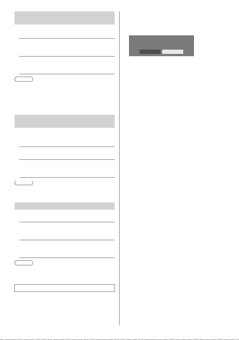
Power on message(No activity power
off)
Sets to show/hide [No activity power off] precautions at
the time the unit is turned on.
[On]:
The warning precautions are shown at the time of
power ON.
[Off]:
The warning precautions are not shown at the time
of power ON.
Note
●
This setting is enabled only when [No activity power
off] is [Enable] (see page 83).
●
The warning precautions are not shown when
OpenPort PLATFORM input is used at the time of
power ON.
Power on message(Power
management)
Whether to show/hide an information message that tells
the power has been turned off by “Power management”
function when the power is set to [On].
[On]:
The information is shown at the time of power [On].
[Off]:
The information is not shown at the time of power
[On].
Note
●
This setting is enabled only when “Power
management” function is [On] (see page 81).
Press <- (Unit)> together with <RETURN>
and hold for more than 5 seconds.
[Shipping] is displayed and the lock is released when
it disappears.
Shipping
YES NO
●
Settings for [Button lock], [Controller user level]
and [Controller ID function] will be back to [Off].
POWER button lock
Sets the lock setting for the display <Main Power On /
Off button>.
[On]:
<Main Power On / Off button> operation is
disabled.
[Off]:
<Main Power On / Off button> operation is
enabled.
Note
●
This function is only for TH-55AF1U, TH-49AF1U and
TH-42AF1U.
Initialization
When both main unit buttons and remote control buttons
are disabled due to the [Button lock], [Controller user
level] and [Controller ID function] settings, set all the
values [Off] so that all the buttons are enabled again.
English
96
Page 97

Using Network
USB
OpenPort
PLATFORM
Function
This unit has a network function and you can control the
Display connected to the network using your computer.
With OpenPort PLATFORM input, it is also possible to
display WEB pages, download applications from the
server, etc.
Necessary environment for computers to be connected
First of all, confirm your computer whether it has a wired
LAN or a built-in wireless LAN.
Before connecting the Display to the computer, be sure
to check the following settings.
The requirements described here do not guarantee
proper operation of all wireless LAN adapters or wireless
LAN adapters incorporated in PCs.
■ For wired LAN
Check 1: About LAN cable
●
Connect the cable properly.
●
Use LAN cable that is compatible with category 5 or
above. To connect a device using 1000BASE-T, use
LAN cable that is compatible with category 5e or above.
Check 2: Wired LAN settings
Computer with a built-in wired LAN function
●
Switch on the wired LAN.
Computer without a built-in wired LAN function
●
Check that your wired LAN adapter is recognized
properly and it is switched on.
●
Install the wired LAN adapter driver beforehand.
For details on how to install the driver, refer to the
instructions accompanying the wired LAN adapter.
■ For wireless LAN
Check 1: Wireless LAN settings
Computer with a built-in wireless LAN function
●
Switch on the wireless LAN.
Computer without a built-in wireless LAN function
●
Check that your wireless LAN adapter is recognized
properly and it is switched on.
●
Install the wireless LAN adapter driver beforehand.
For details on how to install the driver, refer to the
instructions accompanying the wireless LAN adapter.
Check 2: PC
●
If the security (firewall) software or utility software of
network card has been installed, connection to the
display may not be possible.
●
Do not set the network bridge.
●
Disable the firewall.
Example of network connection
Note
●
To use the network function, set each item
in [WIRELESS & NETWORKS] in OpenPort
PLATFORM. (see page 55)
●
To control the display connected to the network using
your computer, set each item in [LAN Control] in
OpenPort PLATFORM (see page 54) and make sure
to set [Command Control] to [ON].
To enable startup from the wired LAN or wireless LAN
in standby mode, set [OpenPort PLATFORM standby]
to [On]. (see page 83)
When it is set to [On], power indicator lights orange
under the condition of power “Off” with remote control
(stand-by state).
■ LAN Terminal connection
LAN
Display (Back of the unit)
PC
LAN Terminal
LAN cable (commercially available)
Hub or broadband router
Note
●
For LAN cable, use shielded cable, otherwise picture
noise may be caused.
●
Make sure the broadband router or hub supports
10BASE-T/100BASE-TX/1000BASE-T.
●
In the network condition where both the wired LAN
and wireless LAN operate, the wired LAN is prioritized
for operation. When using the wireless LAN,
disconnect the wired LAN cable.
English
97
Page 98

●
Touching the LAN Terminal with a statically charged
hand (body) may cause damage to the device due to
its discharge.
Do not touch the LAN Terminal or the metal part of
the LAN cable.
●
For instructions on connection, consult your network
administrator.
Command control
Network function of the unit can control the unit in the
same way as serial control from a network.
Supported commands
Commands used in the serial control are supported.
(see page 27)
Control Command via LAN
The communication differs whether [LAN Control] [Control Protocol] in OpenPort PLATFORM is set to
[Protocol1] or [Protocol2].
1. When [Control Protocol] is set to
[Protocol1].
Communicates using the display-specific protocol.
Hash the following data with the MD5 algorithm, and
3
generate a 32-byte hash value.
[zzzzzzzzyyyyy]
zzzzzzzz :
8-byte random number obtained in step 2
yyyyy :
Command control administrator privileges user
●
Default user name and password are as follows:
User name: admin1
Password: panasonic
Command transmission method
Transmit in the following command format
Transmitted data
Header
Hash value
(see
“Connection
method”)
32 bytes 1 byte Undefined 1 byte 1 byte
Control
symbol
(STX)
0x02
Data part
Control
command
(ASCII
character
string)
Control
symbol
(ETX)
0x03
terminal
symbol
Last
(CR)
0x0d
■ When the command control administrator
privileges password has been set (Protect
mode)
Connection method
Obtain the display’s IP address and the port number
1
(Default is 1024), and request connection to the
display.
The IP address and the port number can be obtained
from the following menus.
IP address:
•
[STATUS] in OpenPort PLATFORM (see page 52)
or [WIRELESS & NETWORKS] (see page 55)
Port number:
•
[LAN Control] in OpenPort PLATFORM (see page
54)
The display responds.
2
Response data
[ ]
0x20
Random
number
[zzzzzzzz]
(ASCII
code hex
number)
Data part Space Mode Space
[PDPCONTROL]
(ASCII
character
string)
10 bytes 1 byte 1 byte 1 byte 8 bytes 1 byte
Mode: 1 = Protect mode
[ ]
0x20
[1]
0x31
part
Last
terminal
symbol
(CR)
0x0d
Received data
Control
symbol
(STX)
0x02
1 byte Undefined 1 byte 1 byte
Error response
Error message
“PDPCONTROL
4 bytes or 15 bytes 1 byte
Data part
Control
command
(ASCII
character
string)
“ERR1” : Undefined control
“ERR2” : Out of parameter
“ERR3” : Busy status or
“ERR4” : Timeout or reception
“ERR5” : Wrong data length
ERRA”
Control
symbol
(ETX)
0x03
command
range
reception invalid
period
invalid period
: Mismatching of
password
Last terminal
symbol
(CR)
0x0d
terminal
symbol
Last
(CR)
0x0d
98
English
Page 99
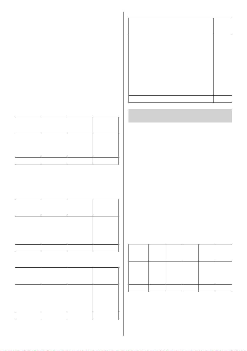
■ When the command control administrator
privileges password has not been set (Nonprotect mode)
Connection method
Obtain the display’s IP address and the port number
1
(Default is 1024), and request connection to the
display.
The IP address and the port number can be obtained
from the following menus.
IP address:
•
[STATUS] in OpenPort PLATFORM (see page 52)
or [WIRELESS & NETWORKS] (see page 55)
Port number:
•
[LAN Control] in OpenPort PLATFORM (see page
54)
The display responds.
2
Response data
Data part Space Mode
[PDPCONTROL]
(ASCII
character
string)
10 bytes 1 byte 1 byte 1 byte
Mode: 0 = Non-protect mode
Command transmission method
Transmit in the following command format
Transmitted data
Control
symbol
(STX)
0x02
1 byte Undefined 1 byte 1 byte
Received data
Control
symbol
(STX)
0x02
1 byte Undefined 1 byte 1 byte
[ ]
0x20
Data part
Control
command
(ASCII
character
string)
Data part
Control
command
(ASCII
character
string)
[0]
0x30
Control
symbol
(ETX)
0x03
Control
symbol
(ETX)
0x03
Last
terminal
symbol
(CR)
0x0d
Last
terminal
symbol
(CR)
0x0d
Last
terminal
symbol
(CR)
0x0d
Error response
Error message
“ERR1” : Undefined control
command
“ERR2” : Out of parameter
range
“ERR3” : Busy status or
reception invalid
period
“ERR4” : Timeout or reception
invalid period
“ERR5” : Wrong data length
4 bytes 1 byte
terminal
symbol
2. When [Control Protocol] is set to
[Protocol2].
Communicates with the same protocol as that of a
Panasonic projector
■ When the command control administrator
privileges password has been set (Protect
mode)
Connection method
Obtain the display’s IP address and the port number
1
(Default is 1024), and request connection to the
display.
The IP address and the port number can be obtained
from the following menus.
IP address:
•
[STATUS] in OpenPort PLATFORM (see page 52)
or [WIRELESS & NETWORKS] (see page 55)
Port number:
•
[LAN Control] in OpenPort PLATFORM (see page
54)
The display responds.
2
Response data
[ ]
0x20
Random
number
part
[zzzzzzzz]
(ASCII
code hex
number)
terminal
symbol
Data part Space Mode Space
[NTCONTROL]
(ASCII
character
string)
9 bytes 1 byte 1 byte 1 byte 8 bytes 1 byte
Mode: 1 = Protect mode
[ ]
0x20
[1]
0x31
Last
(CR)
0x0d
Last
(CR)
0x0d
English
99
Page 100
Hash the following data with the MD5 algorithm, and
3
generate a 32-byte hash value.
[xxxxxx:yyyyy:zzzzzzzz]
xxxxxx :
Command control administrator privileges user
name
yyyyy :
Above administrator privileges user password
●
Default user name and password are as follows:
User name: admin1
Password: panasonic
zzzzzzzz :
8-byte random number obtained in step 2
Command transmission method
Transmit in the following command format
Transmitted data
Header Data part
Hash value
(see
“Connection
method”)
32 bytes 1 byte 1 byte Undefined 1 byte
Received data
‘0’
0x30
1 byte 1 byte Undefined 1 byte
‘0’
0x30
Header Data part
‘0’
0x30
‘0’
0x30
command
character
Control
command
(ASCII
character
Control
(ASCII
string)
terminal
symbol
string)
terminal
symbol
(CR)
0x0d
Last
(CR)
0x0d
Last
Error response
Error message
“ERR1” : Undefined control
command
“ERR2” : Out of parameter range
“ERR3” : Busy status or
reception invalid period
“ERR4” : Timeout or reception
invalid period
“ERR5” : Wrong data length
“ERRA” : Mismatching of
password
4 bytes 1 byte
terminal
symbol
■ When the command control administrator
privileges password has not been set (Nonprotect mode)
Connection method
Obtain the display’s IP address and the port number
1
(Default is 1024), and request connection to the
display.
The IP address and the port number can be obtained
from the following menus.
IP address:
•
[STATUS] in OpenPort PLATFORM (see page 52)
or [WIRELESS & NETWORKS] (see page 55)
Port number:
•
[LAN Control] in OpenPort PLATFORM (see page
54)
The display responds.
2
Response data
[0]
0x30
Last terminal
symbol
(CR)
0x0d
Data part Space Mode
[NTCONTROL]
(ASCII
character
string)
9 bytes 1 byte 1 byte 1 byte
Mode: 0 = Non-protect mode
[ ]
0x20
Last
(CR)
0x0d
100
English
 Loading...