

Page 1
Wide Plasma Display
®
PLASMA DISPLAY
+
L
O
V
—
T
U
P
N
I
Y
B
D
N
A
/
T
S
-
R
R
N
E
O
W
R
E
O
P
W
O
P
G
Operating Instructions
TH-37PW4
Model No.
TH-42PW4
Before connecting, operating or adjusting this product, please read these instructions completely. Please keep this
manual for future reference.
English
TQBC0293-1
Page 2

Dear Panasonic Customer
Welcome to the Panasonic family of customers. We hope that you will have many years of
enjoyment from your new Plasma Display.
To obtain maximum benefit from your set, please read these Instructions bef ore ma kin g any
adjustments, and retain them for future reference.
Retain your purchase receipt also, and note down the model number and
serial number of your set in the space provided on the rear cover of these instructions.
Visit our Panasonic Web Site http://www.panasonic.co.jp/global/
Trademark Credits
VGA is a trademark of International Business Machines Corporation.
•
S-VGA is a registered trademark of the AV Electronics Standard Association.
•
Even if no special notation has been made of company or product trademarks, these trademarks have been
fully respected.
Note:
Do not allow a still picture to be displayed for an extended period, as this can cause a permanent after-image to
remain on the Plasma Display.
Examples of still pictures include logos, video games, computer images, teletext and images displayed in 4:3 mode.
2
Page 3

Table of Contents
Important Safety Notice..............................................4
Safety Precautions......................................................5
Accessories .................................................................7
Accessories Supply....................................................7
Optional Accessories .................................................7
Remote Control Batteries...........................................8
Connections ................................................................9
A V Input Terminals connection.................................10
Component/RGB Input connection ..........................11
How to connect the PC Input Terminals ...................13
How to connect the SERIAL Terminals ....................14
Basic Controls...........................................................15
Power On/Off and input signal selection ................16
AC cord connection..................................................16
Power On/Off ...........................................................16
Select the input signal..............................................17
Selecting the On-Screen Menu Language...............17
On screen Menu Display from Remote Control......18
ASPECT Controls......................................................20
Adjusting Picture Pos./Size .....................................22
Sound Adjustment ....................................................24
Mute .........................................................................24
Surround Controls ....................................................25
Picture Adjustments .................................................26
Screensaver (For preventing after-images) ............28
Side panel Adjustment .............................................29
Setup for input signals .............................................30
Component/RGB-in select .......................................30
3D Y/C Filter – For NTSC video images ..................30
Colour system / Panasonic Auto..............................31
[Sync] .......................................................................32
[Pull-in range]...........................................................32
[Clamp position] .......................................................32
[H-Freq. (kHz)/V-Freq. (Hz)] .....................................32
Troubleshooting ........................................................33
Specifications............................................................34
3
Page 4
Important Safety Notice
WARNING: To prevent damage which may result in fire or shock hazard, do not expose this appliance to
rain or moisture.
Do not place containers with water (flower vase, cups, cosmetics, etc.) above the set. (including
on shelves above, etc.)
WARNING: 1) To prevent electric shock, do not remove cover. No user serviceable parts inside. Refer servicing
to qualified service personnel.
2) Do not remove the earthing pin on the power plug. This apparatus is equipped with a three pin
earthing-type power plug. This plug will only fit an earthing-type power outlet. This is a safety
feature. If you are unable to insert the plug into the outlet, contact an electrician.
Do not defeat the purpose of the earthing plug.
WARNING
This is a class A product. In a domestic environment this product may cause radio interference in which case you
may be required to take adequate measures.
CAUTION
This appliance is intended for use in environments which are relatively free of electromagnetic fields.
Using this appliance near sources of strong electromagnetic fields or where electrical noise may overlap with the
input signals could cause the picture and sound to wobble or cause interference such as noise to appear.
To avoid the possibility of harm to this appliance, keep it away from sources of strong electromagnetic fields.
To prevent electric shock, ensure the grounding pin on the AC cord power plug is securely connected.
4
Page 5

Safety Precautions
WARNING
Setup
This Plasma Display is for use only with the following optional accessories. Use with any other type of
optional accessories may cause instability which could result in the possibility of injury.
(All of the following accessories are manufactured by Matsushita Electric Industrial Co., Ltd.)
Speakers......................................... TY-SP37P4W-S(TH-37PW4), TY-SP42PM3W(TH-42PW4)
•
Pedestal ..........................................TY-ST42PT3-S
•
Wall stand .......................................TY-ST42PW1
•
Mobile stand.................................... TY-ST42PF3(TH-42PW4)
•
Wall-hanging bracket (vertical)........TY-WK37PV3(TH-37PW4), TY-WK42PV1(TH-42PW4)
•
Wall-hanging bracket (angled) ........TY-WK42PR1(TH-42PW4)
•
Ceiling unit ......................................TY-CE42PS1
•
Always be sure to ask a qualified technician to carry out set-up.
Do not place the Plasma Display on sloped or unstable surfaces.
The Plasma Display may fall off or tip over.
•
Do not place any objects on top of the Plasma Display.
If water is spills onto the Plasma Display or foreign objects get inside it, a short-circuit may occur which could
•
result in fire or electric shock. If any foreign objects get inside the Plasma Display, please consult your local
Panasonic dealer.
If using the pedestal (optional accessory), leave a space of at least 10 cm at the top, left and right, at least 6
cm at the bottom, and at least 7 cm at the rear. If using some other setting-up method, leave a space of a
least 10 cm at the top, bottom, left and right, and at least 1.9 cm at the rear.
Avoid installing this product near electronic equipment that generates electromagnetic waves.
It will cause interference in image, sound, etc. In particular, keep video equipment away from this product.
•
When using the Plasma Display
The Plasma Display is designed to operate on 220 - 240 V AC, 50/60 Hz.
Do not cover the ventilation holes.
Doing so may cause the Plasma Display to overheat, which can cause fire or damage to the Plasma Display.
•
Do not stick any foreign objects into the Plasma Display.
Do not insert any metal or flammable objects into the ventilations holes or drop them onto the Plasma Display,
•
as doing so can cause fire or electric shock.
Do not remove the cover or modify it in any way.
High voltages which can cause severe electric shocks are present inside the Plasma Display . For any
•
inspection, adjustment and repair work, please contact your local Panasonic dealer.
Securely insert the power cord plug as far as it will go.
If the plug is not fully inserted, heat may be generated which could cause fire. If the plug is damaged or the wall
•
socket plate is loose, they shall not be used.
Do not handle the power cord plug with wet hands.
Doing so may cause electric shocks.
•
Do not do anything that may damage the power cable. When disconnecting the power cable, pull on the
plug body, not the cable.
Do not damage the cable, make any modifications to it, place heavy objects on top of it, heat it, place it near
•
any hot objects, twist it, bend it excessively or pull it. To do so may cause fire and electric shock. If the power
cable is damaged, have it repaired at your local Panasonic dealer.
If the Plasma Display is not going to be used for any prolonged length of time, unplug the power cord plug
from the wall outlet.
5
Page 6

Safety Precautions
If problems occur during use
If a problem occurs (such as no picture or no sound), or if smoke or an abnormal odour starts to come out
from the Plasma Display, immediately unplug the power cord plug from the wall outlet.
If you continue to use the Plasma Display in this condition, fire or electric shock could result. After checking that
•
the smoke has stopped, contact your local Panasonic dealer so that the necessary repairs can be made.
Repairing the Plasma Display yourself is extremely dangerous, and shall never be done.
If water or foreign objects get inside the Plasma Display, if the Plasma Display is dropped, or if the cabinet
becomes damages, disconnect the power cord plug immediately.
A short circuit may occur, which could cause fire. Contact your local Panasonic dealer for any repairs that need
•
to be made.
CAUTION
When using the Plasma Display
Do not bring your hands, face or objects close to the ventilation holes of the Plasma Display .
Heated air comes out from the ventilation holes at the top of Plasma Display will be hot. Do not bring your hands
•
or face, or objects which cannot withstand heat, close to this port, otherwise burns or deformation could result.
Be sure to disconnect all cables before moving the Plasma Display.
If the Plasma Display is moved while some of the cables are still connected, the cables may become damaged,
•
and fire or electric shock could result.
Disconnect the power cord plug from the wall socket as a safety precaution before carrying out any cleaning.
Electric shocks can result if this is not done.
•
Clean the power cable regularly to prevent it becoming dusty.
If dust built up on the power cord plug, the resultant humidity can damage the insulation, which could result in
•
fire. Pull the power cord plug out from the wall outlet and wipe the mains lead with a dry cloth.
Cleaning and maintenance
The front of the display panel has been specially treated. Wipe the panel surface gently using only a
cleaning cloth or a soft, lint-free cloth.
If the surface is particularly dirty, wipe with a soft, lint-free cloth which has been soaked in pure water or water
•
to which a small amount of neutral detergent has been added, and then wipe it evenly with a dry cloth of the
same type until the surface is dry.
Do not scratch or hit the surface of the panel with fingernails or other hard objects, otherwise the surface may
•
become damaged. Furthermore, avoid contact with volatile substances such as insect sprays, solvents and
thinner, otherwise the quality of the surface may be adversely affected.
If the cabinet becomes dirty, wipe it with a soft, dry cloth.
If the cabinet is particularly dirty, soak the cloth in water to which a small amount of neutral detergent has been
•
added and then wring the cloth dry. Use this cloth to wipe the cabinet, and then wipe it dry with a dry cloth.
Do not allow any detergent to come into direct contact with the surface of the Plasma Display .
•
If water droplets get inside the unit, operating problems may result.
Avoid contact with volatile substances such as insect sprays, solvents and thinner, otherwise the quality of the
•
cabinet surface may be adversely affected or the coating may peel off. Furthermore, do not leave it for long
periods in contact with articles made from rubber or PVC.
6
Page 7
Accessories
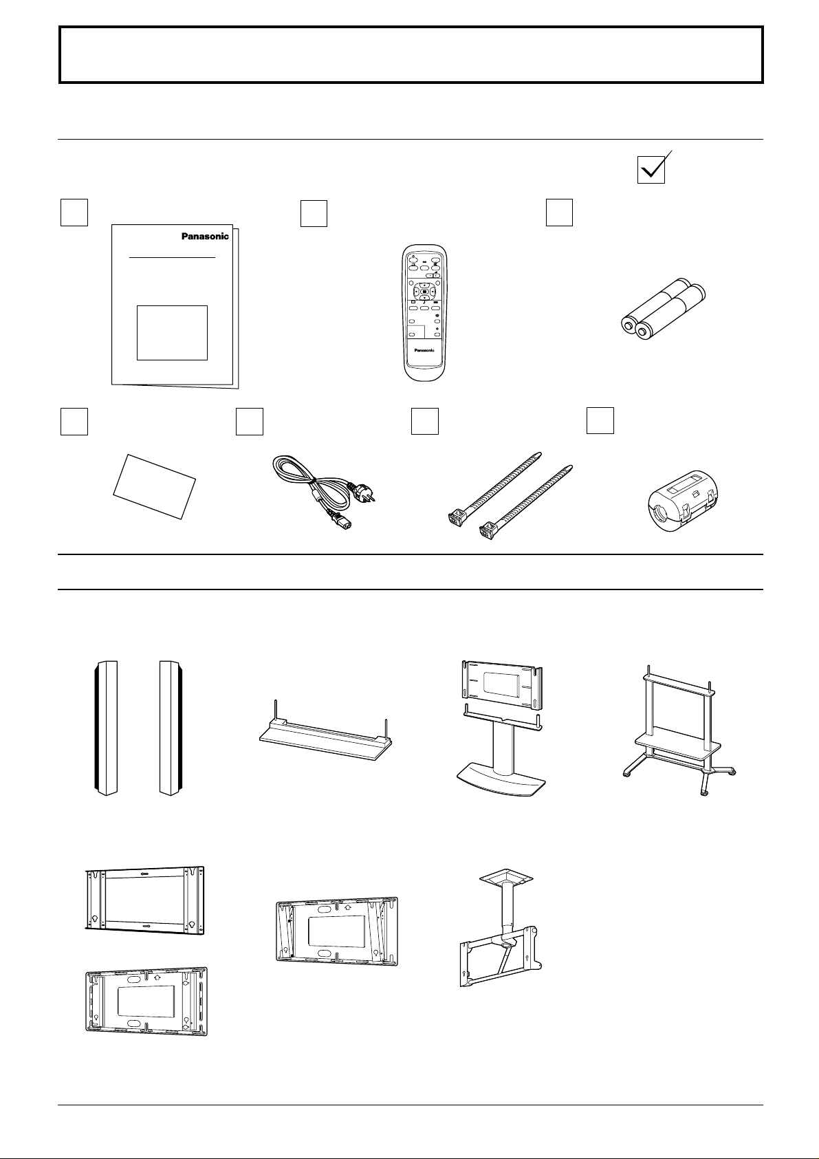
Accessories Supply
Check that you have the accessories and items shown
Operating Instruction book
Remote Control Transmitter
EUR646525
Guarantee Card
AC cord
Optional Accessories
INPUT
SURROUND
VOL
NR
PICTURE
SET UP
SOUND
PICTURE
POS. /SIZE
ASPECT
OFF TIMER
PC
PLASMA DISPLAY
Fixing bands
TMME187 × 2
Batteries for the Remote
Control Transmitter
(2 × R6 Size)
Ferrite core
J0KF00000018 × 2
Speakers
•
TY-SP37P4W-K(TH-37PW4)
TY-SP42PM3W(TH-42PW4)
Wall-hanging bracket
•
(vertical)
TY-WK37PV3(TH-37PW4)
TY-WK42PV1(TH-42PW4)
Pedestal
•
TY-ST42PT3-S
Wall-hanging bracket
•
(angled)
TY-WK42PR1(TH-42PW4)
Wall stand
•
TY-ST42PW1
Ceiling unit
•
TY-CE42PS1
• Mobile stand
TY-ST42PF3(TH-42PW4)
For assembling
Full instructions are supplied with each optional accessory for use with this Plasma Display.
7
Page 8
Remote Control Batteries
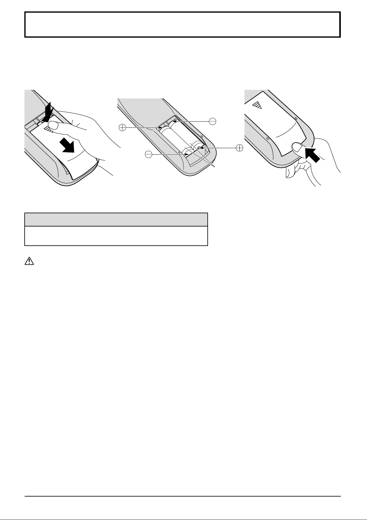
Requires two R6 batteries.
1. Turn the transmitter face down.
Press and slide off the battery
cover.
2. Install the batteries as shown in
the battery compartment.
(Polarity + or – must match the
markings in the compartment).
3. Replace the cover and slide in
reverse until the lock snaps.
Two "R6" size
Helpful Hint:
For frequent remote control users, replace old batteries with
Alkaline batteries for longer life.
Precaution on battery use
Incorrect installation can cause battery leakage and corrosion that will damage the remote control transmitter.
Observe the following precaution:
1. Batteries shall always be replaced as a pair. Always use new batteries when replacing the old set.
2. Do not combine a used battery with a new one.
3. Do not mix battery types (example: “Zinc Carbon” with “Alkaline”).
4. Do not attempt to charge, short-circuit, disassemble, heat or burn used batteries.
5. Battery replacement is necessary when remote control acts sporadically or stops operating the Plasma Display
set.
8
Page 9
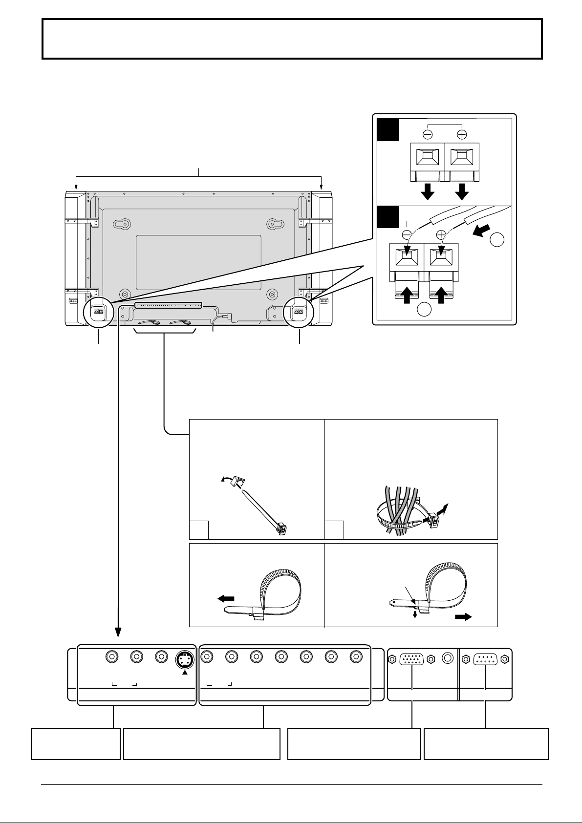
Connections
When connecting the speakers, be sure to use only the optional accessory speakers.
Refer to the speaker’s Installation Manual for details on speaker installation.
1
Speakers (Optional accessories)
2
1
2
SPEAKERS
Terminals (R)
SPEAKERS
Terminals (L)
– Cable fixing bands
Secure any excess cables with bands as required.
Pass the attached cable fixing
band through the clip as
shown in the figure.
To secure cables connected to
Terminals, wrap the cable fixing band
around them then pass the pointed end
through the locking block, as shown in
the figure.
1
To tighten:
Pull
2
To loosen:
Push
the catch
Pull
AV IN Terminals
(see page 10, 11)
RL
AUDIO
S VIDEOVIDEO
RL
AUDIO
COMPONENT/RGB IN and Audio
IN Terminals (see page 11, 12 )
AUDIO
HD
VD
COMPONENT/RGB INAV IN
From EXIT monitor Terminal
on Computer (see page 13)
PR/CR/R
P
B/CB
/B Y/G
PC IN SERIAL
From SERIAL Terminal on
Computer (see page 14)
9
Page 10
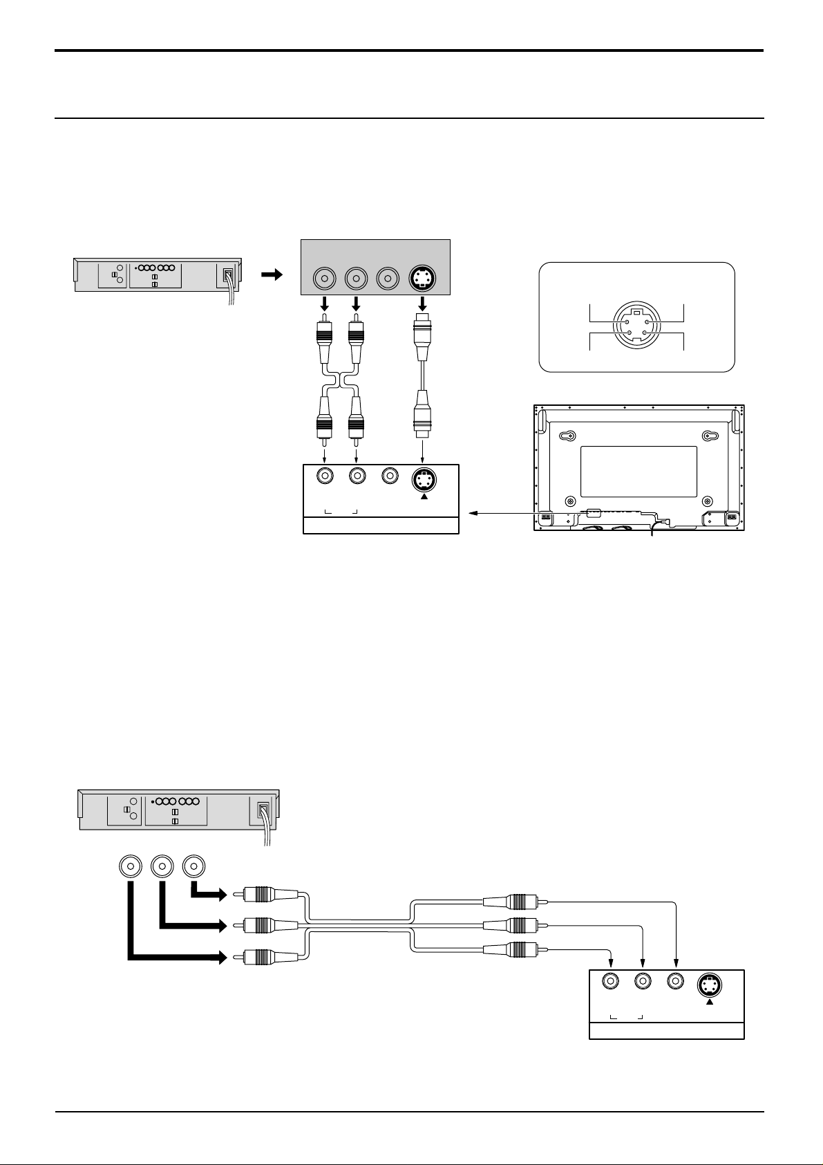
Connections
AV Input Terminals connection
Connect the signal source equipment.
(Example) When connecting an S VIDEO VCR
(S VIDEO VCR)
2×RCA audio
cables
AUDIO
Audio input to
L/R sockets
Audio
OUT
RL
RL
AUDIO
AV IN
Video
OUT
S Video
OUT
S VIDEO
Video input to
S VIDEO
socket
S VIDEOVIDEO
S VIDEO 4 pin socket
Luminance earth
Luminance in
Chrominance earth
Chrominance in
(Example) When connecting 3×RCA audio video cables.
(VCR)
Audio
OUT
RL
Video
OUT
AUDIO-VIDEO
Video input to
RCA socket
3×RCA audio
video cables
Audio input to
L/R sockets
Note:
Additional equipment and cables shown are not supplied with this set.
RL
AUDIO
AV IN
S VIDEOVIDEO
10
Page 11
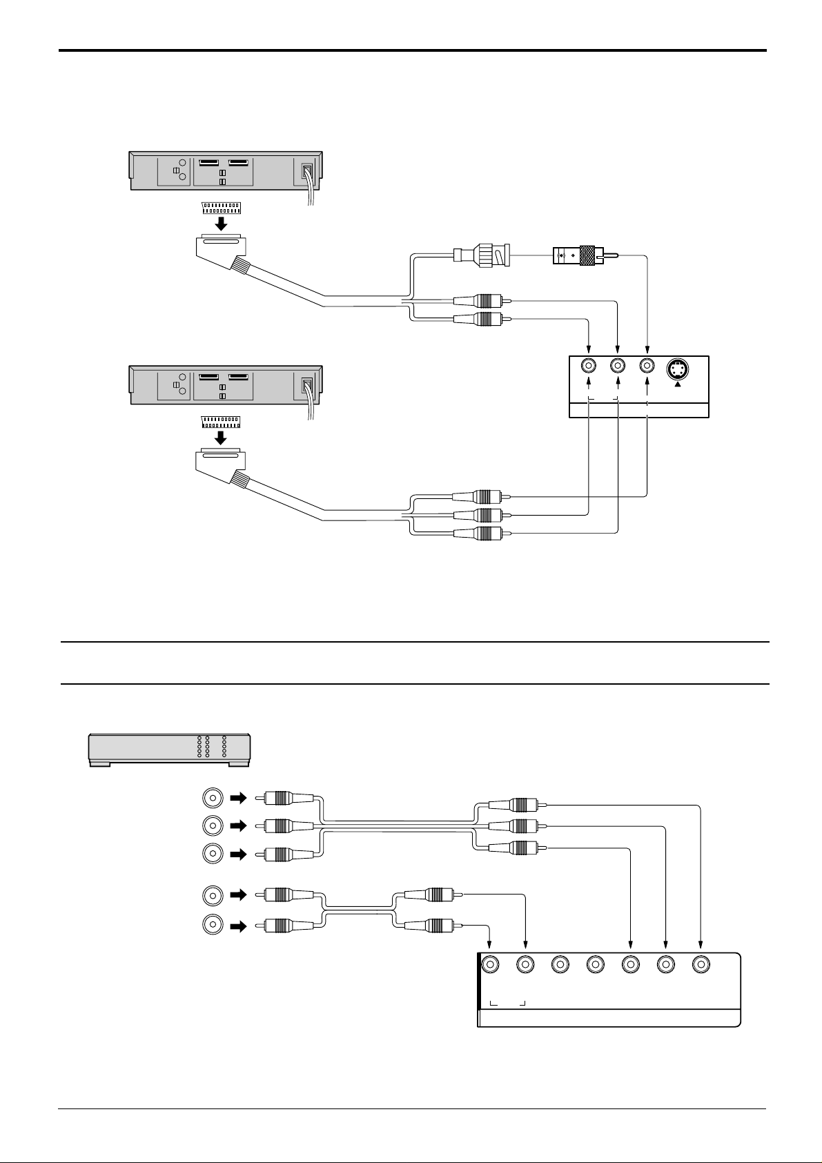
(Example) When connecting 21 pin scart cables.
(VCR)
AV2
Connections
Video input to
BNC socket
BNC-RCA
adaptor plug
Audio input to
(DVD / Satellite Receiver)
AV1/TV
L/R sockets
RL
AUDIO
Video input to
RCA socket
Audio input to
L/R sockets
Notes:
(1) Additional equipment, cables and an adapter plug shown are not supplied with this set.
(2) 21 pin connectors and 21 pin scart plugs are connectors used in Europe.
S VIDEOVIDEO
AV IN
Component/RGB Input connection
Component signals (Y, PB, PR) connection
(DVD Player)
Y
Y, PB, P
P
B
P
R
L
R
3×RCA
video cables
AUDIO
2×RCA
audio cables
Notes:
(1) Change the “Component/RGB-in” setting in the “Setup” enu to “Component”. (see page 30, 32)
(2) Additional equipment and cables shown are not supplied with this set.
R
RL
AUDIO
HD
VD
PR/CR/R
COMPONENT/RGB IN
P
B/CB
/B Y/G
11
Page 12
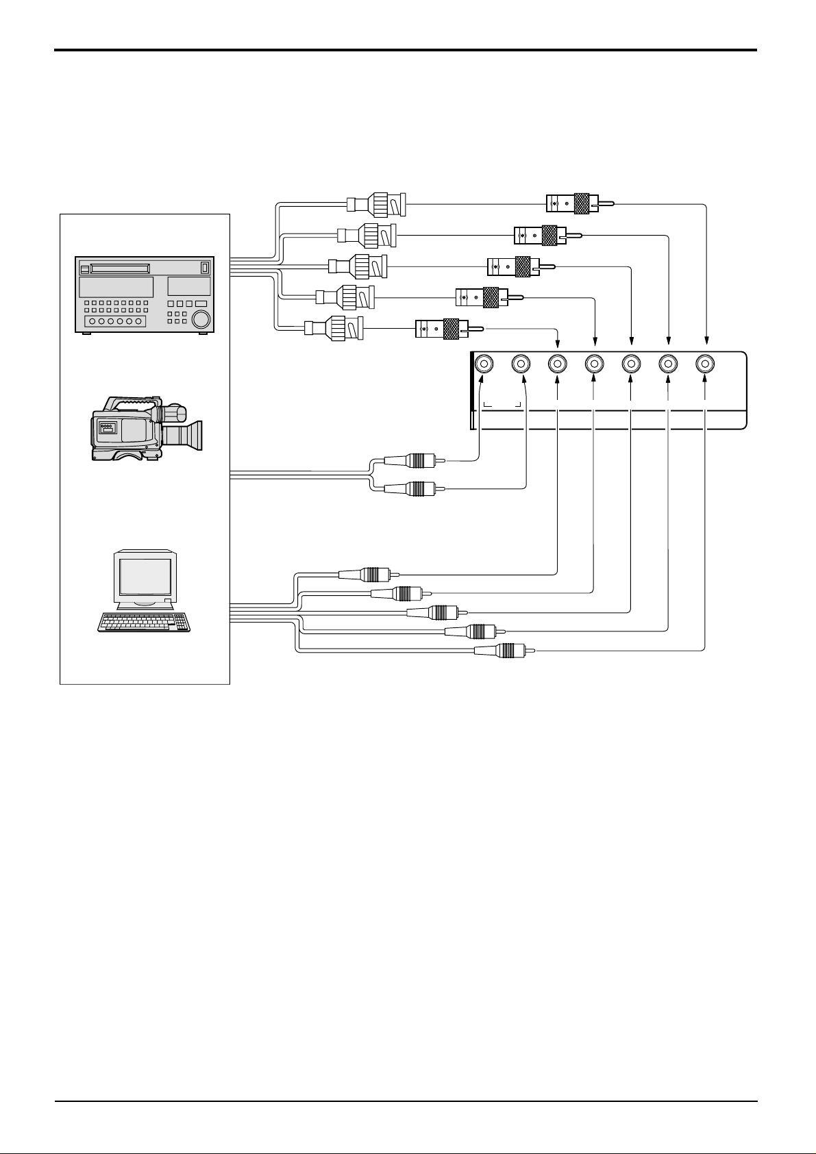
Connections
RGB signal (R, G, B, HD, VD) connection
Example of input signal source
HDTV-compatible VCR
RGB camera
Computer
RGB input to
R, G, B, HD, VD sockets
5×BNC
RGB cables
AUDIO
2×RCA audio cables
Audio input to
L/R sockets
BNC-RCA
adaptor plug
RL
AUDIO
P
R/CR
HD
VD
/R
COMPONENT/RGB IN
P
B/CB
/B
Y/G
VD
HD
R
B
G
Notes:
(1) Change the “Component/RGB-in” setting in the “Setup” menu to “RGB”. (see page 30, 32)
(2) Additional equipment, cables and adapter plugs shown are not supplied with this set.
12
Page 13
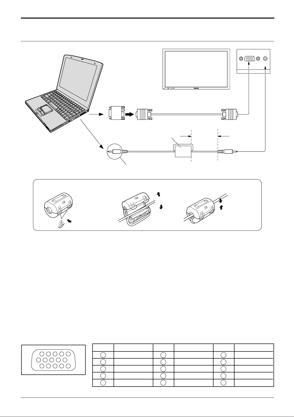
How to connect the PC Input Terminals
1
67839
45
10
1514131211
2
COMPUTER
–
VOL
+
INPUT
POWER /
R - STANDBY
G POWER ON
Connections
AUDIO
PC IN
Conversion adapter (if necessary)
D-sub 15p
RGB
PC cable
Ferrite core
(supplied)
Less than
7
7"
/
8
(20 cm)
Audio
1/8" (3mm) stereo plug
Connect a cable which matches
the audio output terminal on the computer.
Installing the ferrite core
1
2
3
Open
Pull back the tabs
(in two places)
Press the cable
through and close
Notes:
(1) Computer signals which can be input are those with a horizontal scanning frequency of 15.5 to 110 kHz and
vertical scanning frequency of 48 to 120 Hz. (However, signals cannot be displayed if signals exceeding 1200
lines will not be displayed properly .)
(2) The display resolution is a maximum 640 × 480 dots when the aspect mode is set to “4:3”, and 852 × 480 dots
when the aspect mode is set to “16:9”. If the display resolution exceeds these maximums, it may not be possible
to show fine detail with sufficient clarity.
(3) The PC input terminals are DDC1/2B-compatible. If the computer being connected is not DDC1/2B-compatible,
you will need to make setting changes to the computer at the time of connection.
(4) Some PC models cannot be connected to the set..
(5) There is no need to use an adapter for computers with DOS/V compatible D-sub 15P terminal.
(6) The computer shown in the illustration is for example purposes only.
(7) Additional equipment and cables shown are not supplied with this set.
(8) Do not set the horizontal and vertical scanning frequencies for PC signals which are above or below the
specified frequency range.
Signal Names for D-sub 15P Connector
Pin Layout for PC Input
Terminal
Pin No.
1
2
3
4
5
Signal Name
R
G
B
GND (Ground)
GND (Ground)
Pin No.
6
7
8
9
10
Signal Name
GND (Ground)
GND (Ground)
GND (Ground)
NC (not connected)
GND (Ground)
Pin No.
11
12
13
14
15
Signal Name
GND (Ground)
SDA
HD/SYNC
VD
SCL
13
Page 14
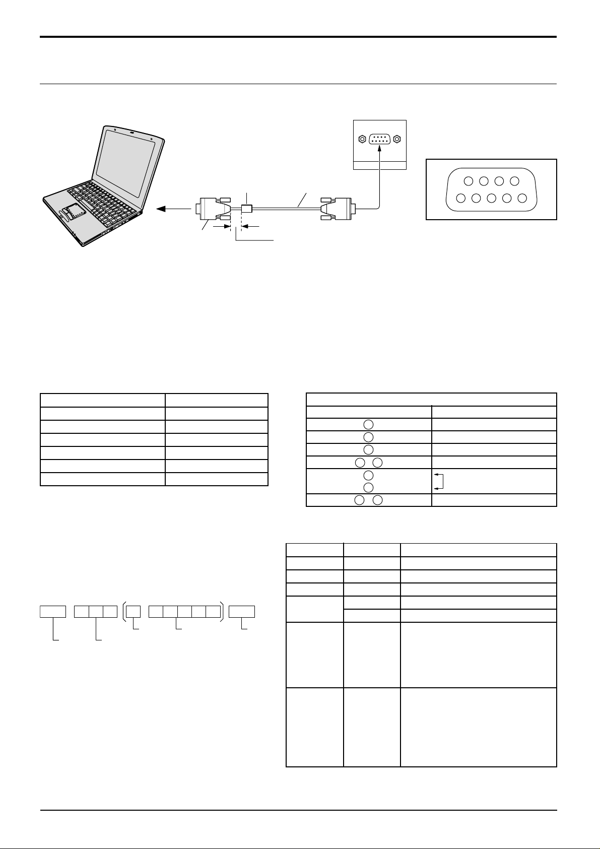
Connections
How to connect the SERIAL Terminals
The SERIAL terminal is used when the Plasma Display is controlled by a computer.
COMPUTER
SERIAL
9876
53214
Pin layout for RS-232C
D-sub 9p
Ferrite core
(supplied)
RS-232C
straight cable
Less than
7
7"
/8 (20 cm)
Notes:
(1) Use the RS-232C cable to connect the computer to the Plasma Display.
(2) The computers shown is for example purposes only.
(3) Additional equipment and cables shown are not supplied with this set.
The SERIAL terminal conforms to the RS-232C interface specification, so that the Plasma Display can be controlled
by a computer which is connected to this terminal.
The computer will require software which allows the sending and receiving of control data which satisfies the
conditions given below. Use a computer application such as a programming language to software. Refer to the
documentation for the computer application for details.
Communication parameters
Signal level
Synchronization method
Baud rate
Parity
Character length
Stop bit
Flow control
RS-232C compliant
Asynchronous
9600 bps
None
8 bits
1 bit
-
D-sub 9-pin female
RS-232C Conversion cable
2
3
5
4 6
7
8
1 • 9
Details
R X D
T X D
GND
Non use
Shorted
NC
Basic format for control data
The transmission of control data from the computer
starts with a STX signal, followed by the command,
the parameters, and lastly an ETX signal in that
order. If there are no parameters, then the
parameter signal does not need to be sent.
STX
Start
(02h)
Colon Parameter(s)
3-character
command (3bytes)
(1 - 5 bytes)
ETX:C2C1 C3 P2P1 P3 P4 P5
End
(03h)
Notes:
(1) If multiple commands are transmitted, be sure to
wait for the response for the first command to
come from this unit before sending the next
command.
(2) If an incorrect command is sent by mistake, this
unit will send an “ER401” command back to the
computer.
14
Command
Command
PON
POF
AVL
AMT
IIS
Parameter
None
None
**
0
1
None
VID
YP1
Power ON
Power OFF
Volume 00 - 63
Audio mute OFF
Audio mute ON
Input select (toggle)
AV Mode
Component / RGB mode (processed as a
Control details
Y/PB/PR or RGB signals as set by this unit)
PC Mode
Screen mode select (toggle)
4 : 3
Zoom
16 : 9
Just
Panasonic Auto
DAM
RG1
None
NORM
ZOOM
FULL
JUST
SELF
With the power off, this display responds to PON command only .
Page 15
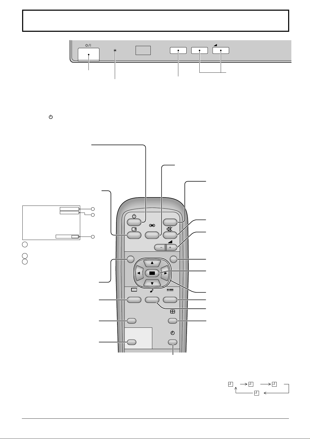
Basic Controls
R - STANDBY
G POWER ON
TH-42PW4
Main Power On/Off Switch
Power Indicator
The Power Indicator will light.
Power-OFF..... Indicator not illuminated (The
•
unit will still consume some power as long as
the power cord is still inserted into the wall
outlet.)
Stand-by ....Red
•
Power-ON......Green
•
(A V (S Video)/Component, RGB/PC
Mode Selection)
Push the “INPUT” button to select AV(S
Video)/
signal modes sequentially.
(see page 17)
Stand-by (ON/OFF) button
The Plasma Display must first be plugged into the wall
outlet and turned on at the power switch (see page 16).
Push this button to turn the Plasma Display On, from
Stanby mode. Push it again to turn the Plasma Display
Off t o S tanby mode.
Status button
Push the “Status” button to display
the current system status.
AV
4:3
Off timer 90
1
2
3
1 AV(S Video)/Component, RGB/
PC mode
2 Aspect mode (see page 20)
NR
3 Off timer
The off timer indicator is displayed
only when the off timer has been set.
N button
(see page 23, 24, 26)
PICTURE
PICTURE button
(see page 26)
PICTURE
POS. /SIZE
PICTURE POS./SIZE button
(see page 22)
PC
PC button
Push the “PC” mode selection
button to select the PC mode.
This button is used to switch
directly to PC mode.
The Plasma Display may be preset to switch to stand-by after a fixed period. The
OFF TIMER button
setting changes to 30 minutes, 60 minutes, 90 minutes and 0 minutes (off timer
cancelled) each time the button is pressed.
When three minutes remain, “Off timer 3” will flash.
The off timer is cancelled if a power interruption occurs.
INPUT button
Component
SURROUND
VOL
SOUND
SET UP
OFF TIMER
INPUT
–
or RGB/PC input
SURROUND button
(see page 25)
INPUT
ASPECT
VOL
+
V olume Adjustment
Push the Volume Up “+”
or Down “–” button to
increase or decrease the
sound volume level.
INPUT button
(AV(S Video)/Component, RGB/
PC Mode Selection)
Press to select AV(S Video)/
Component or RGB/PC input signal
modes sequentially . (see page 17)
Sound mute On/Off (see page 24)
V olume Adjustment
Press the Volume Up “+” or Down
“–” button to increase or decrease
the sound volume level.
R button
ACTION button
Press to make selections
POSITION buttons
SET UP button (see page 18)
SOUND button (see page 24)
ASPECT button
Press to adjust the aspect.
(see page 20)
30 60
90
0
15
Page 16
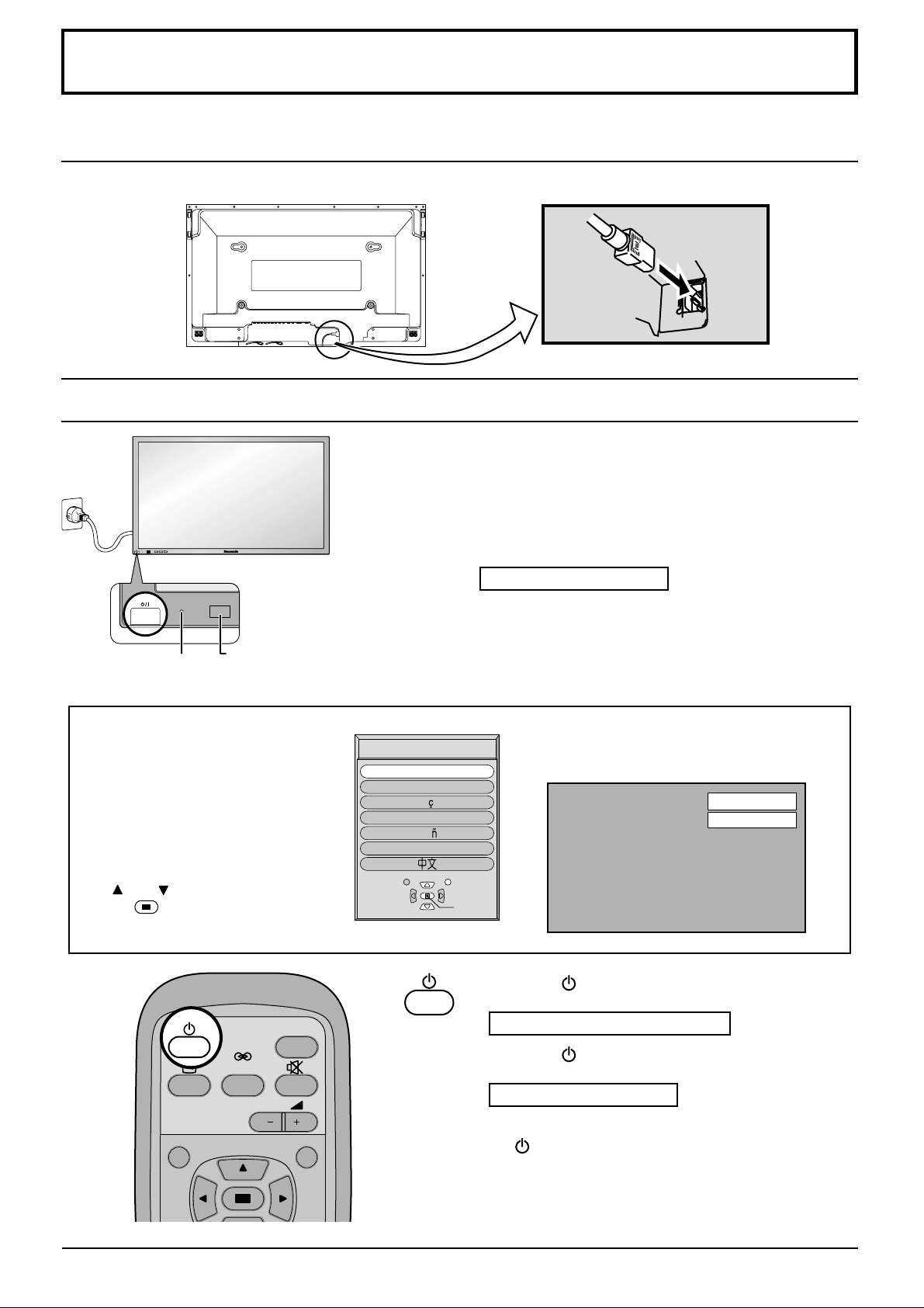
Power On/Off and input signal selection
AC cord connection
Connecting the AC cord plug to the Plasma Display.
Power On/Off
Connecting the plug to the Wall Outlet
Note:
Main plug types vary between countries. The power
plug shown at left may, therefore, not be the type
fitted to your set.
INPUT
–
VOL
+
R - STANDBY
G POWER ON
R - STANDBY
G POWER ON
TH-42PW4
Power Indicator
Remote Control Sensor
When the Power is turned on for the
first time, the Language selection
screen is displayed.
From the second time on, language
selection can be done from the
setup menu. (see page 17)
Select the desired language using
the
Action
and
keys and press the
button.
NR
INPUT
SURROUND
VOL
OSD Language
English (UK
Deutsch
Fran ais
Italiano
p
a ol
Es
ENGLISH (US
Select
Push the Power switch on the Plasma Display to turn
the set on Power-On
Power Indicator: Green
Example: The screen below is displayed for a while
after the Plasma Display is turned on.
(setting condition is an example.)
From the second time on, the below screen
is
displayed for a while (setting condition is
)
an example).
AV
4:3
)
Set
Press the
button on the remote control to turn the
Plasma Display off
Power Indicator: Red (standby)
Press the
button on the remote control to turn the
Plasma Display on
Power Indicator: Green
Turn the power to the Plasma Display set off by pressing
the
switch on the Plasma Display , when the Plasma
Display is on or in standby mode.
16
Page 17
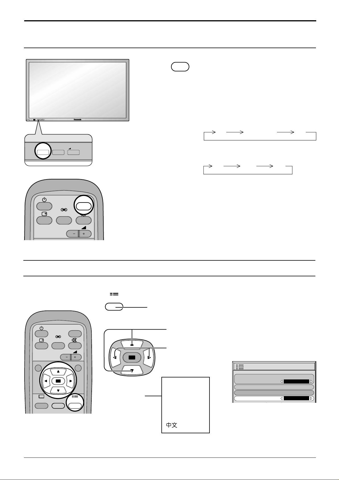
Power On/Off and input signal selection
AV Component PC
Select the input signal
INPUT
— VOL +
R - STANDBY
G POWER ON
INPUT
Press the INPUT button to select the input
A V signal desired from equipment such as a
VCR which has been connected to the
Plasma Display .
Input signals will change as follows:
For Component Input (see page 30)
INPUT
— VOL +
For RGB Input (see page 30)
AV RGB PC
INPUT
SURROUND
VOL
Selecting the On-Screen Menu Language
SET UP
Press to display the Setup menu.
INPUT
SURROUND
VOL
NR
PICTURE
SOUND
SET UP
selectable
languages
Press to select the OSD Language.
Press to select your
preferred language.
Setup
Component/RGB-in select
English(UK)
Deutsch
Français
OSD Lan
Italiano
Español
ENGLISH(US)
.........
(Chinese)
guag
g
Si
Screensaver
e
nal
En
RGB
g
lish (UK
)
17
Page 18
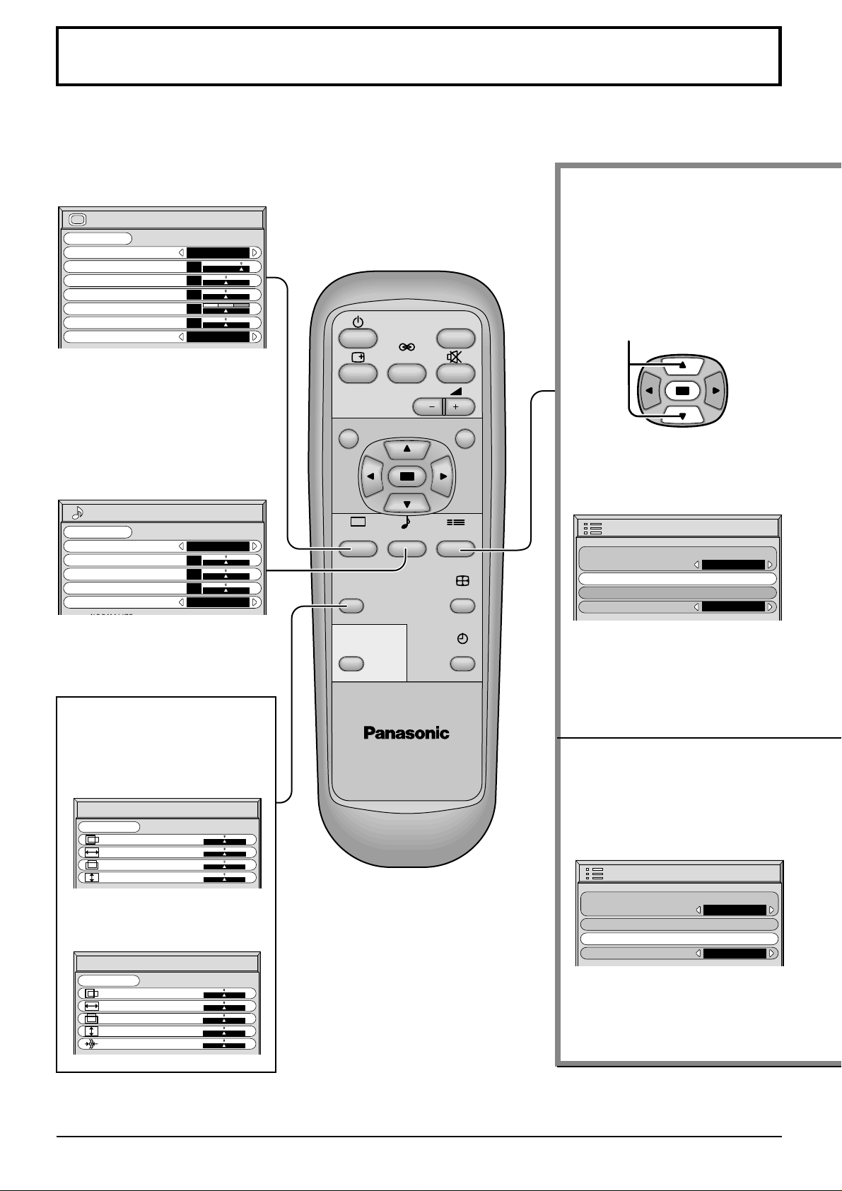
On-Screen Menu Display from Remote Control
To Picture adjust menu
(see page 26)
Picture
Normalise
Picture Mode
Contrast
Brightness
Colour
Tint
Sharpness
White balance
To Sound adjust menu
(see page 24)
Normal
Dynamic
20
0
0
0
0
Normal
INPUT
SURROUND
VOL
NR
Press to select each item.
Sound
Normalise
Sound Mode
Bass
Treble
Balance
Surround
Normal
Normal
0
0
0
On
To Picture Pos./Size adjust
menu (see page 22)
During “AV” and “Component”
input signal modes.
Picture Pos./Size
Normalise
Normal
H-Pos
H-Size
V-Pos
V-Size
During “RGB” and “PC”
input signal modes.
Picture Pos./Size
Normalise
Normal
H-Pos
H-Size
V-Pos
V-Size
Clock Phase
PICTURE
PICTURE
POS. /SIZE
PC
PLASMA DISPLAY
SOUND
SET UP
ASPECT
OFF TIMER
Setup
Component/RGB-in select
g
nal
Si
Screensaver
guag
OSD Lan
e
En
Setup
Component/RGB-in select
g
nal
Si
Screensaver
guag
OSD Lan
e
En
RGB
g
lish (UK
RGB
g
lish (UK
)
)
18
Page 19
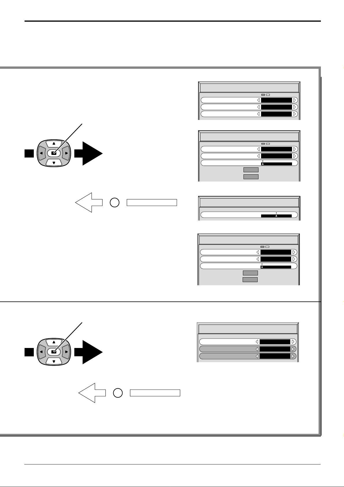
On-Screen Menu Display from Remote Control
Press to select “Signal” menu
To Signal screen for AV (see page 31)
On
Auto
4 : 3
[
AV
[
RGB
Signal
To Signal screen for AV (see page 31)
3D Y/C Filter (NTSC
Colour system
Panasonic Auto (4:3
To Signal screen for RGB (see page 32)
Signal
)
)
]
]
Sync
Pull-in range
Clamp position
H
-
Freq. kHz
-
Freq. Hz
V
R
Press the R buttun to return
to “Setup” menu.
Note:
“Signal” setup menu displays different setting condition for each input signals. (see page 17)
To Signal screen for Component (see page 32)
Signal
To Signal screen for PC (see page 32)
Clamp position
To Signal screen for PC (see page 32)
Signal
Sync
Pull-in range
Clamp position
H
-
Freq. kHz
-
Freq. Hz
V
31.5
60.0
31.5
60.0
H & V
Narrow
[
Component
H & V
Narrow
[
PC
]
]
Press to setup “Screensaver”
menu.(see page 28)
R
Press the R buttun to return
to “Setup” menu.
Screensaver
Function
Mode
SP Adjustment
White bar scroll
On
Off
19
Page 20
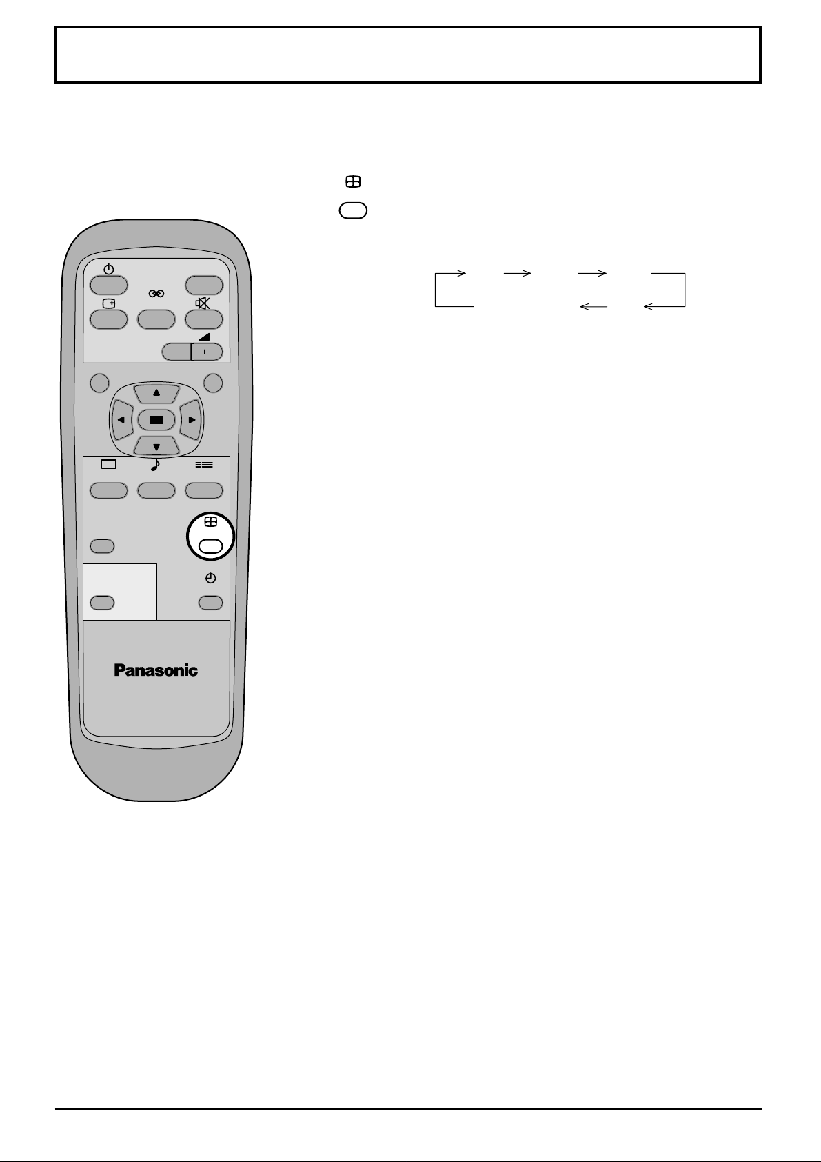
ASPECT Controls
The Plasma Display will allow you to enjoy viewing the picture at its maximum size, including wide screen cinema
format picture.
INPUT
SURROUND
VOL
NR
PICTURE
PICTURE
POS. /SIZE
PC
SOUND
SET UP
ASPECT
OFF TIMER
ASPECT
ASPECT button
The aspect mode changes each time the ASPECT button
is pressed.
4 : 3 Zoom 16 : 9
Panasonic Auto Just
Notes:
(1) During RGB and PC input signal modes, the mode switches
between “4:3”, “Zoom” and “16:9” only.
(2) For a 525p (480p) signal input during “Component” input signal
mode, the mode switches between “Zoom” and “16:9” only.
(3) For a 1125i (1080i), 750p (720p) signal input during “Component”
input signal mode, the mode is set to “16:9” mode, and switching
is not possible.
For a 525i (480i), 625i (576i) signal input during “Component”
input signal mode, “Panasonic Auto” can not be selected.
(4) The aspect mode is memorized separately for each input terminal
(AV, Component, RGB and PC).
PLASMA DISPLAY
20
Page 21
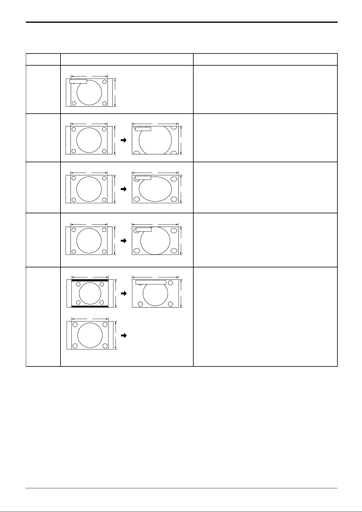
ASPECT Controls
Mode
4 : 3
Zoom
16 : 9
Just
4 : 3
Picture
4
3
4
3
4
3
4
3 9
16
Zoom
9
16
16 : 9
9
16
Just
4:3 will display a 4:3 picture at its standard 4:3 size.
Zoom mode magnifies the central section of the
picture.
16:9 will display the picture at its maximum size but
with sight elongation.
Just mode will display a 4:3 picture at its maximum
size but with aspect correction applied to the center
of the screen so that elongation is only apparent at
the left and right edges of the screen. The size of
Explanation
the picture will depend on the original signal.
416
Panasonic Auto
39
The display will automatically become enlarged
(depending on the picture source), allowing you to
view the picture at its maximum size.
Note:
Panasonic
Auto
For an elongated image
4
3
For a 4:3 image
Image is expanded
Changes in accordance
with the Panasonic Auto
mode setting (see page
31)
Panasonic Auto mode is designed to automatically
adjust the aspect ratio to handle a mix of 16:9 and
4:3 program material. Certain 4:3 program material,
such as stock market data screens, may
occasionally cause the image size to change
unexpectedly. When viewing such programs, it is
recommended that the ASPECT be set to 4:3.
Notes:
(1) Do not allow 4:3 mode to be displayed for an extended period, as this can cause a permanent after-image to remain
on the Plasma Display Panel.
(2) The S Video terminal on this set can detect specially encoded signals that are compatible with a wide screen
monitor. When a full image from the S Video terminal of specially encoded video is detected by the set, the screen
size is automatically set to 16:9 mode.
21
Page 22
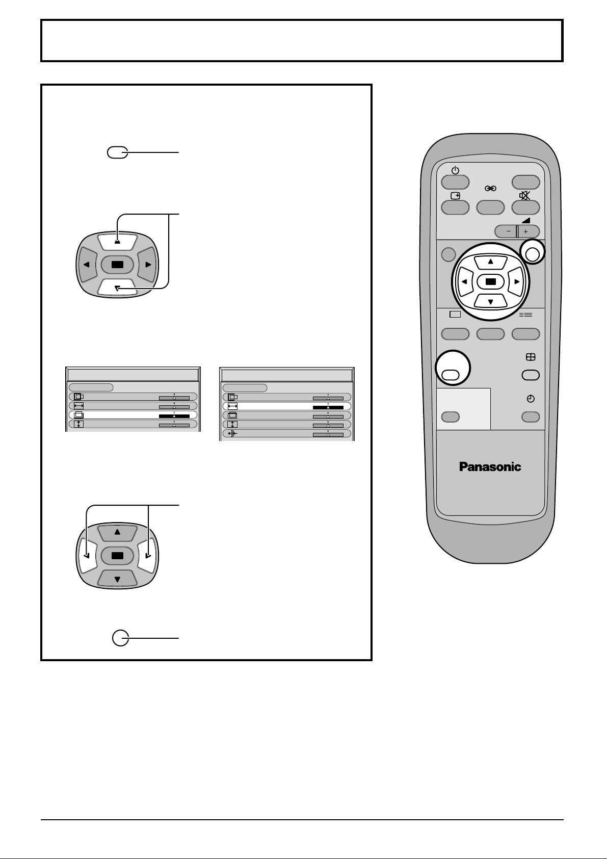
Adjusting Picture Pos./Size
Adjusting screen
1
PICTURE
POS. /SIZE
2
During “AV” and “Component”
input signal modes.
Picture Pos./Size
Normalise
Normal
H-Pos
H-Size
V-Pos
V-Size
Press to display the Picture Pos./Size
menu.
Press to select H-Pos/H-Size/V-Pos/VSize/Clock Phase.
During “RGB” and “PC”
input signal modes.
Picture Pos./Size
Normalise
Normal
H-Pos
H-Size
V-Pos
V-Size
Clock Phase
N
PICTURE
PICTURE
POS. /SIZE
PC
SURROUND
VOL
SOUND
INPUT
R
SET UP
ASPECT
OFF TIMER
PLASMA DISPLAY
3
R
Press to adjust Pos./Size.
Press to exit from adjust mode.
Notes:
(1) Adjustment details are memorized separately for dif ferent input signal formats (Adjustments for component
signals are memorized for 525i (480i), 625i (576i), 525p (480p), 1125i (1080i) and 625p (576p), 750p (720p)
each, and RGB/PC signals are memorized for each frequency.)
(2) If a “Cue” or “Rew” signal from a VCR or DVD player is received, the picture position will shift up or down. This
picture position movement cannot be controlled by the Picture Pos./Size function.
22
Page 23
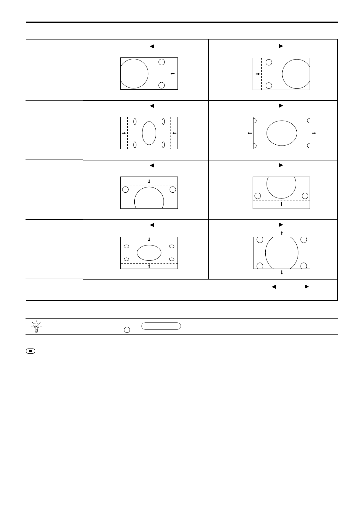
Adjusting Picture Pos./Size
H-Pos
H-Size
V-Pos
When the Position Left
When the Position Left
When the Position Left
“ ”
button is pressed.
“ ”
button is pressed.
“ ”
button is pressed.
When the Position Right
When the Position Right
When the Position Right
“ ”
button is pressed.
“ ”
button is pressed.
“ ”
button is pressed.
“ ”
button is pressed.
“ ”
or Right
“ ”
button
/
“ ”
button is pressed.
Normalise
Normalisation)
When the Position Left
V-Size
Clock Phase
(RGB/PC in Mode)
Helpful Hint (
While the Picture Pos./Size display is active, if either the N button on the remote control is pressed at any time or the
(Action button) is pressed during “Normalise”, then all adjustment values are returned to the factory settings.
Flickering and distortion can be eliminated by using the Position Left
to carry out adjustment.
N
When the Position Right
23
Page 24
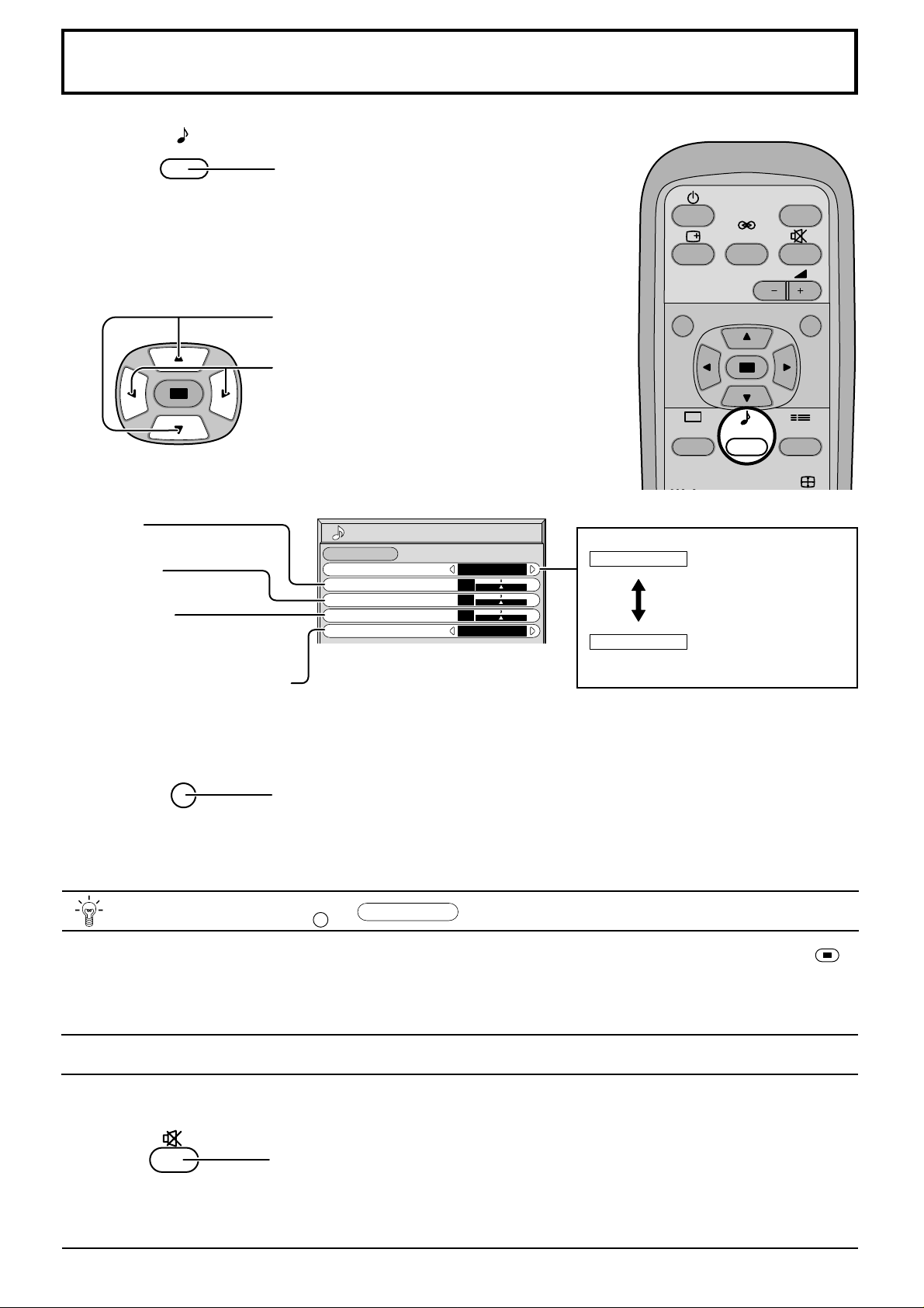
Sound Adjustment
1
Select to adjust each item.
2
Bass
Adjusts low sounds
Treble
Adjusts high sounds
Balance
Adjusts left and right
volumes
Surround (see next page)
Select On or Off
SOUND
Press to display the Sound menu.
Press to select the desired adjustment menu.
Select the desired level by listening to the sound.
Sound
Normalise
Sound Mode
Bass
Treble
Balance
Surround
Normal
Normal
0
0
0
On
Normal
Auto
INPUT
SURROUND
VOL
NR
PICTURE SET UP
PICTURE
SOUND
Emits the original
sound.
Automatically controls
proper volume level.
To end adjustments
•
R
Press the R button
Note:
Press the SURROUND button to directly turn the surround effect On and Off. (see next page)
Helpful Hint (
While the “Sound” menu is displayed, if either the N button on the remote control is pressed at any time or the
(Action button) is pressed during “Normalise”, then all adjustment values are returned to the factory settings.
N
/
Normalise
Normalisation)
Mute
Useful when answering the phone or receiving unexpected visitors.
Press this button to mute the sound.
Press again to reactivate sound. Sound is also reactivated when power is turned off
or volume level is changed.
24
Page 25
Surround Controls
INPUT
SURROUND
VOL
NR
PICTURE SET UP
PICTURE
POS. /SIZE
PC
SOUND
ASPECT
OFF TIMER
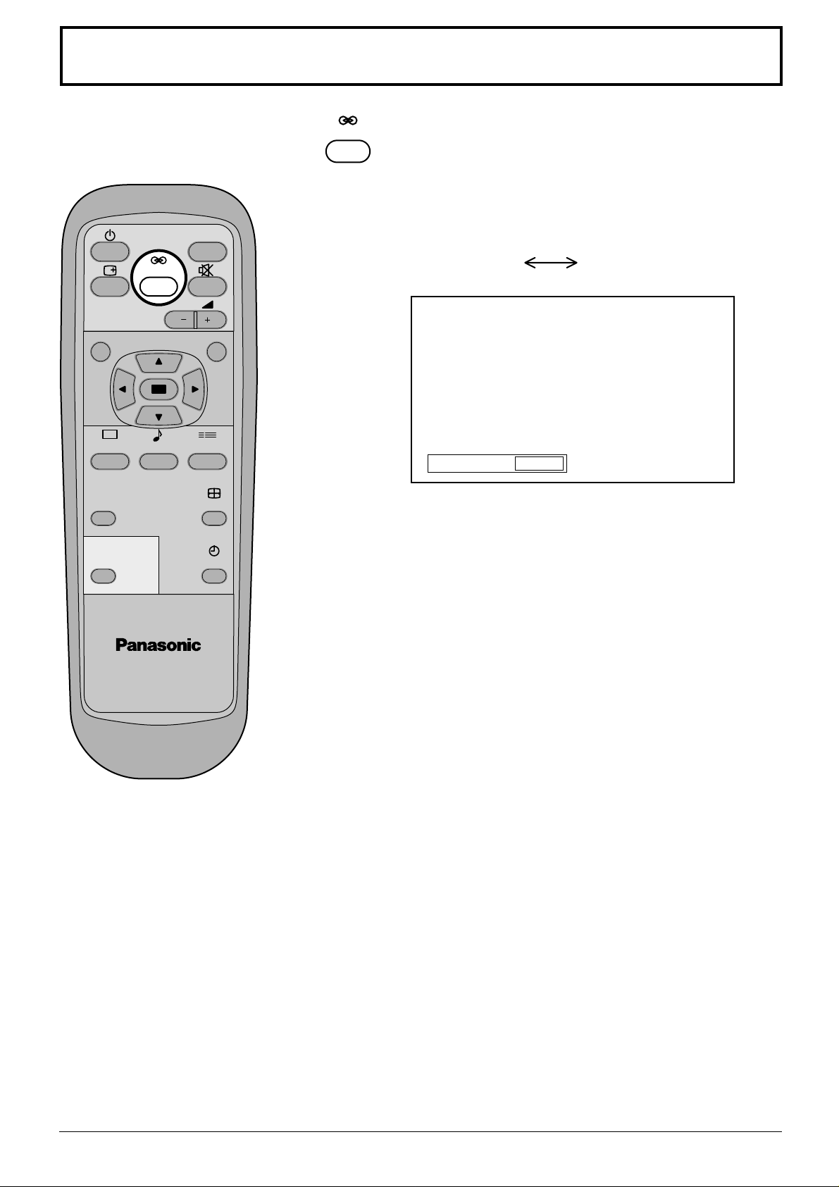
SURROUND
SURROUND Button
The benefits of surround sound are enormous. You can be
completely enveloped in sound; just as if you were at a
concert hall or cinema.
The surround setting switches on and off each time the
SURROUND button is pressed.
On Off
Surround
Note:
The surround settings are memorized separately for each Sound mode
(Auto, Normal).
On
PLASMA DISPLAY
25
Page 26
Picture Adjustments
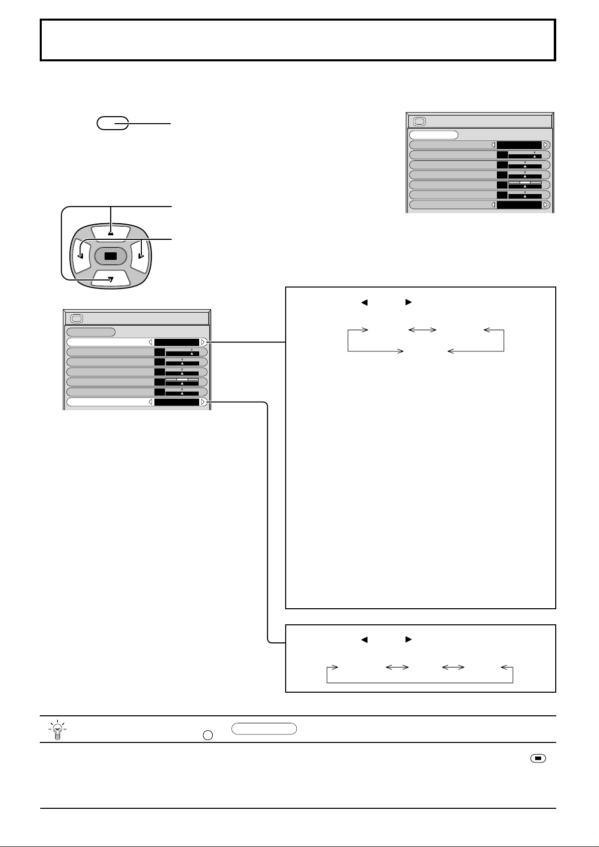
1
2
PICTURE
Select to adjust each item.
Picture
Normalise
Picture Mode
Contrast
Brightness
Colour
Tint
Sharpness
White balance
Normal
Press the PICTURE button on the
Remote Control to display the Picture
menu.
Press to select the menu to adjust.
Select the desired level by looking at the picture
behind the menu.
Press the left
modes.
Normal
20
0
0
0
0
Normal
Normal
For viewing in standard (evening lighting)
environments.
This menu selects the normal levels of
Brightness and Contrast.
Picture
Normalise
Picture Mode
Contrast
Brightness
Colour
Tint
Sharpness
White balance
or right
button to switch between
Normal Dynamic
Cinema
Normal
Normal
20
0
0
0
0
Normal
Helpful Hint (
Dynamic
For viewing in brighter environments.
This menu selects higher than normal
Brightness and Contrast
Cinema
Ideal for movies.
Can be selected for AV/Component.
•
Note:
If you would like to change the picture and colour of
the selected Picture menu to something else, adjust
using the items in the Picture menu. (see next page)
Press the left
modes.
N
/
Normalise
Normalisation)
or right
Normal Cool Warm
.
button to switch between
levels of
While the “Picture” menu is displayed, if either the N button on the remote control is pressed at any time or the
(Action button) is pressed during “Normalise”, then all adjustment values are returned to the factory settings.
26
Page 27
Picture Adjustments
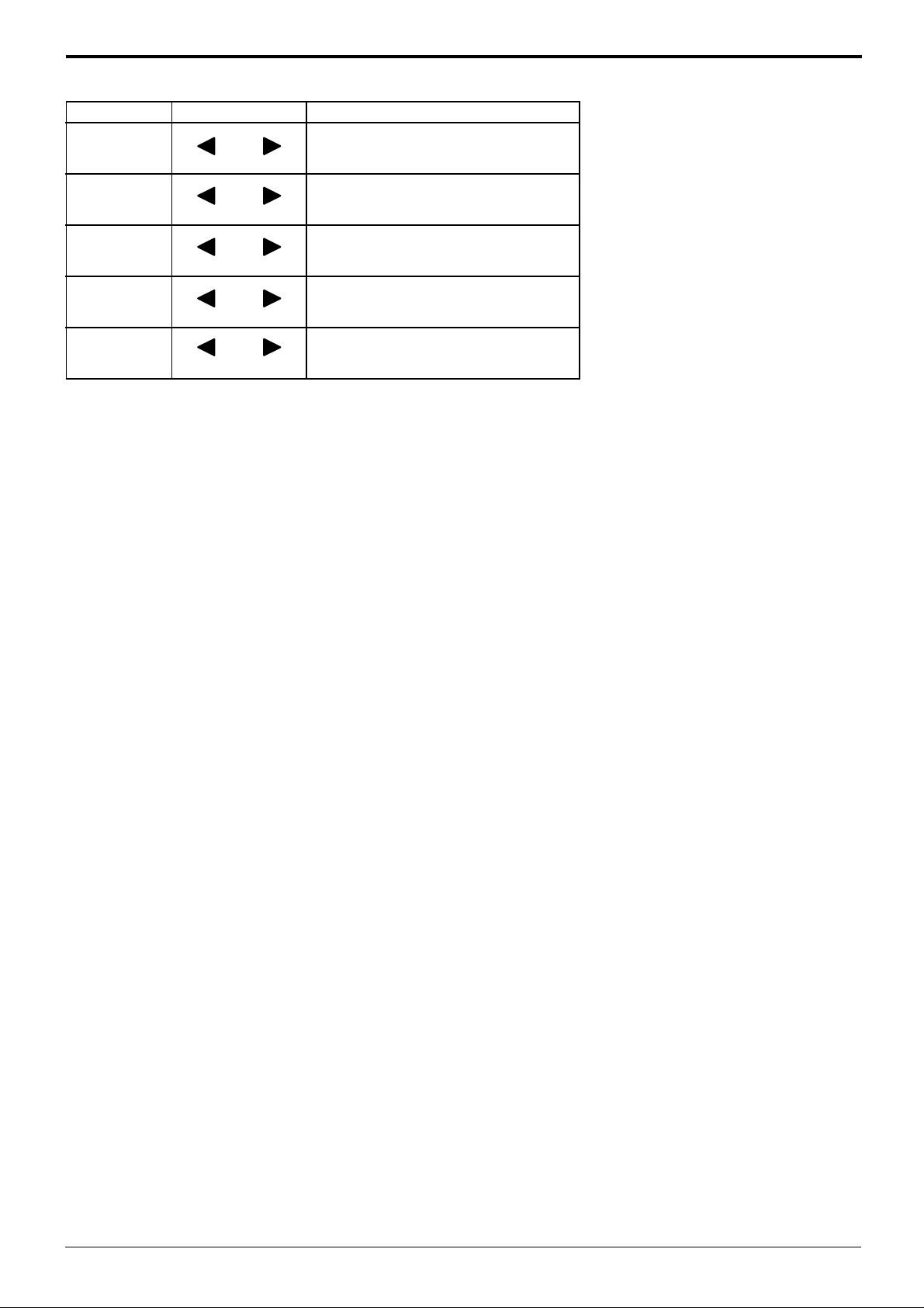
Item
Contrast
Brightness
Colour
Tint
(NTSC only)
Sharpness
Effect Adjustments
Selects the proper brightness and
Less More
density for the room.
Adjusts for easier viewing of dark pictures
Darker Brighter
such as night scenes and black hair.
Adjusts slightly to a lighter colour.
Less More
Adjust for nice skin colour.
Reddish Greenish
Displays a sharp image.
Less More
Notes:
(1)
“Colour” , “Tint” and “Sharpness”
settings cannot be adjusted for
“RGB” and “PC” input signal
modes.
(2) You can change the level of each
Function (Contrast, Brightness,
Colour, Tint, Sharpness) for each
Picture Menu.
(3) The setting details for normal,
dynamic and cinema respectively
are memorized separately for
each input mode (AV, Component,
RGB).
(4) The “Tint” setting can be adjusted
for NTSC signal only .
Note:
There is little change when Picture is increased with a bright picture or reduced with a dark picture.
27
Page 28
Screensaver (For preventing after-images)
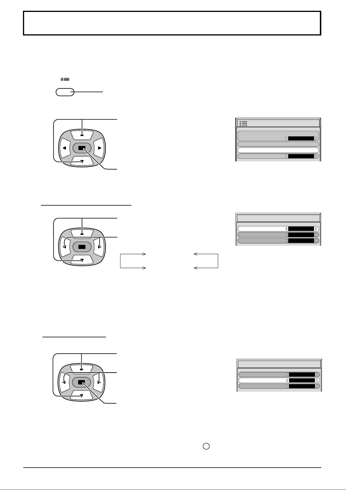
Do not display a still picture, especially in 4:3 mode, for any length of time.
If the display must remain on, a Screensaver should be used.
1
SET UP
2
Reversal / Scroll selection
3
Press to display the Setup menu screen.
Press to select the Screensaver.
Press to select the Screensaver screen.
Press to select the Function.
Press to select the desired function.
Setup
Component/RGB-in select
g
nal
Si
Screensaver
guag
OSD Lan
Screensaver
Function
Mode
SP Adjustment
e
En
White bar scroll
RGB
g
lish (UK
On
Off
)
On / Off selection
4
Image Reversal
White bar scroll
Image Reversall : Negative image will be displayed on the screen.
White bar scroll : The white bar will scroll from left to right.
Press to select the Mode.
Screensaver
Press to select On or Off.
If the mode is at on, the menu screen will
disappear and the Screensaver will be
activated.
Function
Mode
SP Adjustment
White bar scroll
On
Off
28
To stop the Screensaver under On, press the R button.
Page 29
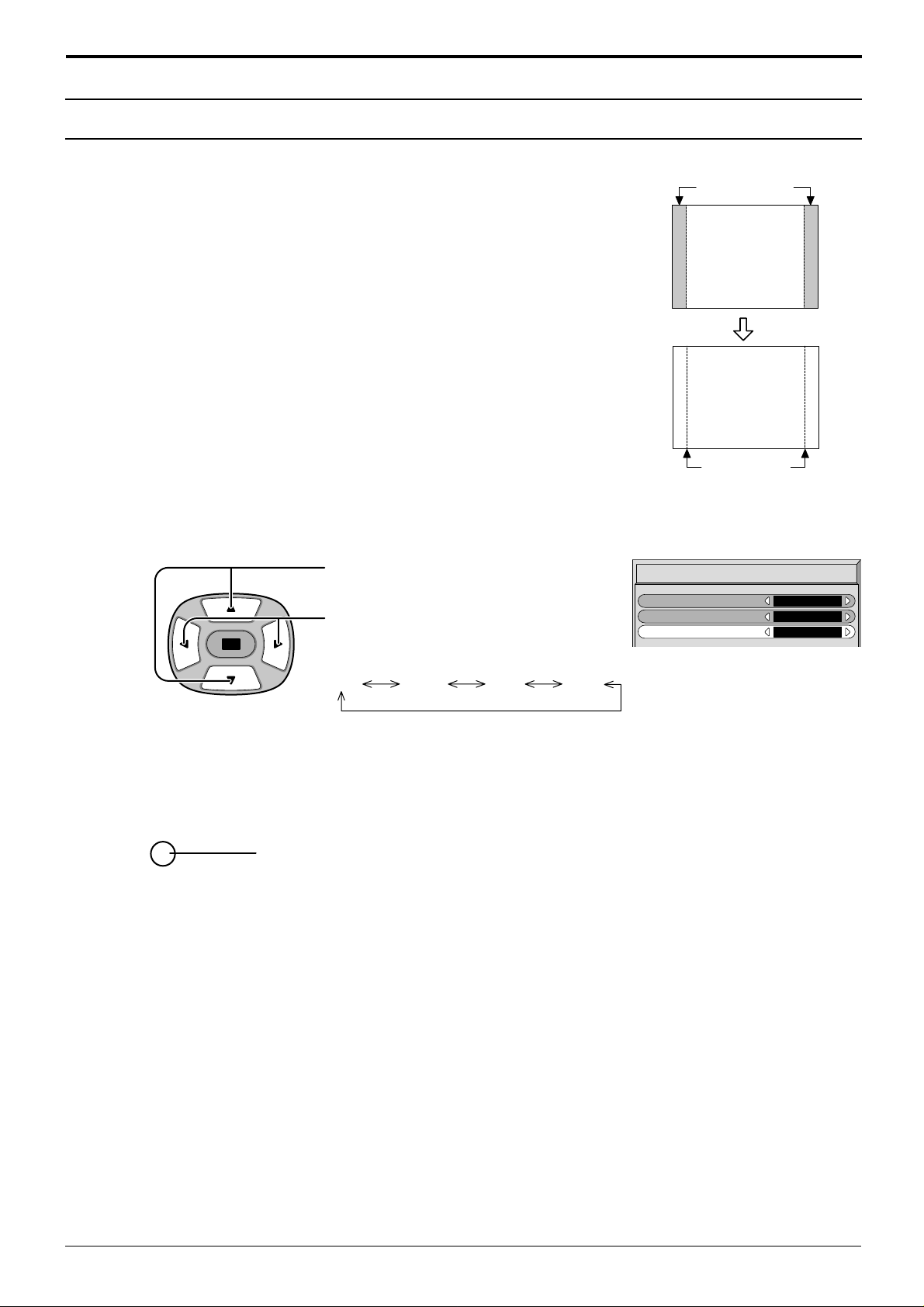
Screensaver
Side Panel Adjustment
(For preventing after-images )
1
2
Do not display a picture in 4:3 mode for an extended period, as
this can cause an after-image to remain on the side panels either
side of the display field.
To prevent the appearance of such an after-image, illuminate the
side panels.
To display the Screensaver screen.
(Refer to the previous page, operation guide steps 1 and 2)
Press to select the SP Adjustment.
Press to select Low, Mid, High.
side panel
Screen Display
after-images
Screensaver
Function
Mode
SP Adjustment
4:3
White bar scroll
On
Off
3
Off Low Mid High
R
Press to exit from Screensaver.
Note:
• Setting the side panel to High mode for an extended period may result in occurence of after-images.
• The side panels may flash (alternate black/white) depending on the picture being shown on the screen. In such an
occurrence, use the Cinema mode.
29
Page 30
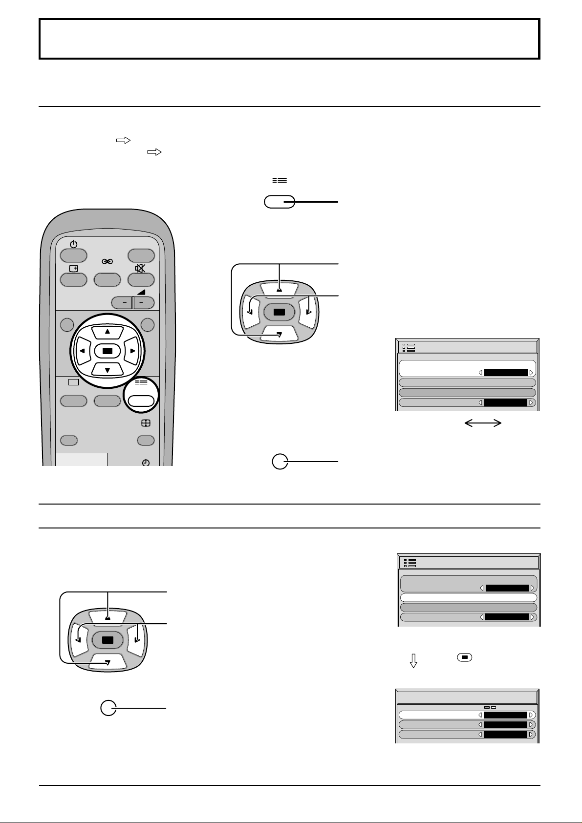
Setup for input signals
Component/RGB-in select
Select to match the signals from the source connected to the Componen/RGB input terminals.
Y, PB, PR signals
R, G, B, HD, VD signals
“Component”
“RGB”
1
SET UP
Press to display the Setup menu screen.
INPUT
SURROUND
VOL
N
PICTURE SET UP
SOUND
2
R
Press to select the “Component/RGB-in
select”.
Press to select the desired mode.
Setup
Component/RGB-in select
guag
OSD Lan
g
Si
Screensaver
e
nal
En
RGB
g
lish (UK
)
PICTURE
POS. /SIZE
ASPECT
R
Press to exit from adjust mode.
3D Y/C Filter – For NTSC video images
Select “Signal” from the “Setup” menu during AV input signal mode. (“Signal
[AV]” menu is displayed.)
Press to select the “3D Y/C Filter (NTSC)”
Press to set On/Off.
R
Press to exit from adjust mode.
Component RGB
Setup
Component/RGB-in select
g
nal
Si
Screensaver
guag
OSD Lan
Signal
3D Y/C Filter (NTSC
Colour system
Panasonic Auto (4:3
e
Press
)
)
RGB
g
En
lish (UK
(Action) button
[
AV
On
Auto
4 : 3
)
]
Note:
When on, this setting only affects NTSC input signals.
30
Page 31
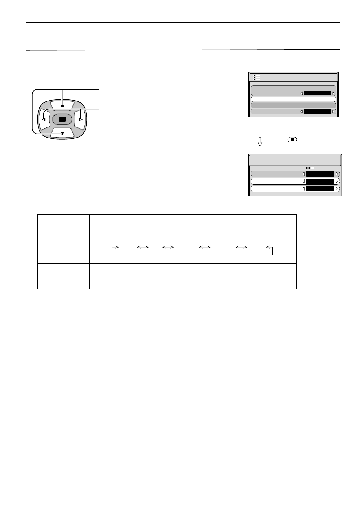
Colour system / Panasonic Auto
Auto PAL SECAM M.NTSC NTSC
Select Signal from the “Setup” menu during AV (S Video) input
signal mode.(“Signal [A V]” menu is displayed.)
Setup for input signals
Setup
Mode
Colour system
Press to select the “Colour system” or “Panasonic
Auto”.
Press to select each functions.
If the picture image becomes unstable:
With the system set on Auto, under conditions of
low level or noisy input signals the image may in
rare cases become unstable. Should this occur,
set the system to match the format of the input
signal.
Function
Set the colour system to match the input signal. If set to “Auto”, the colour system
is determined automatically.
Component/RGB-in select
Si
Screensaver
guag
OSD Lan
e
Press
Signal
3D Y/C Filter (NTSC
Colour system
Panasonic Auto (4:3
g
nal
)
RGB
g
En
lish (UK
(Action) button
On
Auto
)
4 : 3
)
[
AV
]
Pansonic Auto
(4:3)
Set to “4 : 3” to view 4:3 images in an unchanged format when Panasonic
Auto is selected. If you would like to view 4:3 images in “Just” format, set
to “Just”.
31
Page 32
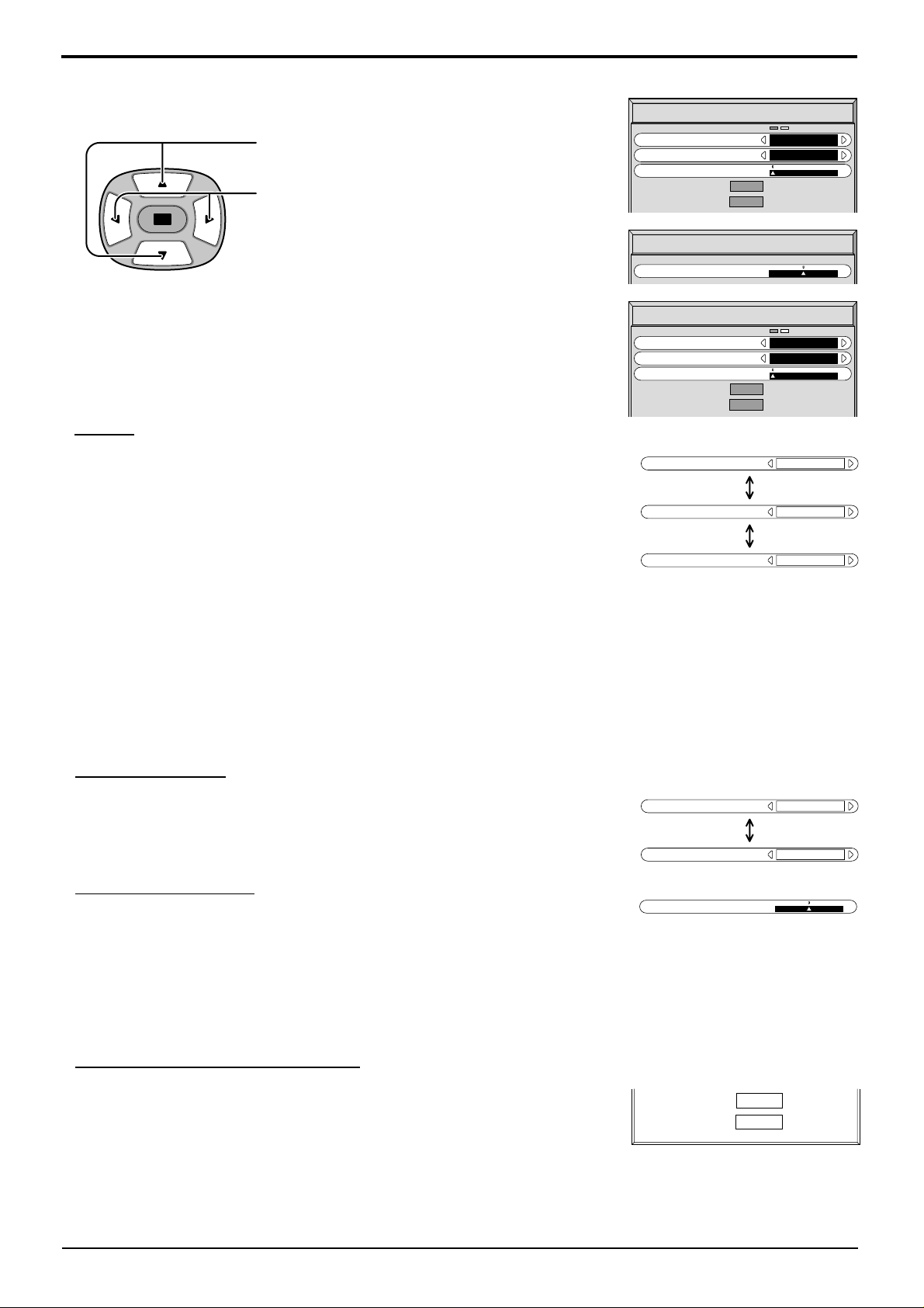
Setup for input signals
Select Signal from the “Setup” menu during RGB or PC input signal mode.
Press to select each item.
Press to adjust.
The following operation methods are the same for both the Signal [RGB]
and Signal [PC].
Sync
Setting RGB sync signal:
Confirm that the input is set to RGB input (this setting is valid only for RGB input).
H&V:
on G: Uses a synchronized signal on the Video G signal, which is input
on VIDEO: Compatible with the scart plug (Europe)
The H and V sync signals are input from the HD/VD connector.
from the G connector.
The composite video signal input from the VIDEO input terminal is
used by dividing the sync signals.
Signal
Sync
Pull-in range
Clamp position
H
-
Freq. kHz
-
Freq. Hz
V
Signal
Clamp position
Signal
Sync
Pull-in range
Clamp position
Sync
Sync
Sync
H
-
Freq. kHz
-
Freq. Hz
V
31.5
60.0
31.5
60.0
[
]
RGB
H & V
Narrow
[
Component
H & V
Narrow
on VIDEO
H & V
on G
[
PC
]
]
Setting PC sync signal:
Confirm that the input is set to PC input (this setting is valid only for PC input).
H&V: The H and V sync signals are input from the HD/VD connector.
on G: Uses a synchronized signal on the Video G signal, which is input from the G connector.
Pull-in range
Sets the width for different frequencies.
(This setting is the same for both Signal [RGB] and Signal [PC].)
Pull-in range
Pull-in range
Clamp position
Clamp position
Adjusts the clamp position.
The following operation methods are the same for “Signal” menu during
Component, RGB and PC input signal mode.
Normally, these adjustments are set to appropriate levels and therefore, do not
need to be altered.
H-Freq (kHz)/V-Freq (Hz)
Displays the H (Horizontal)/V (Vertical) frequencies.
This display is valid only for RGB input and PC input.
Display range:
Horizontal 15.5 - 110 kHz
Vertical 48 - 120 Hz
Narrow
Wide
H-Freq. kHz
V
-
Freq. Hz
31.5
60.0
32
Page 33
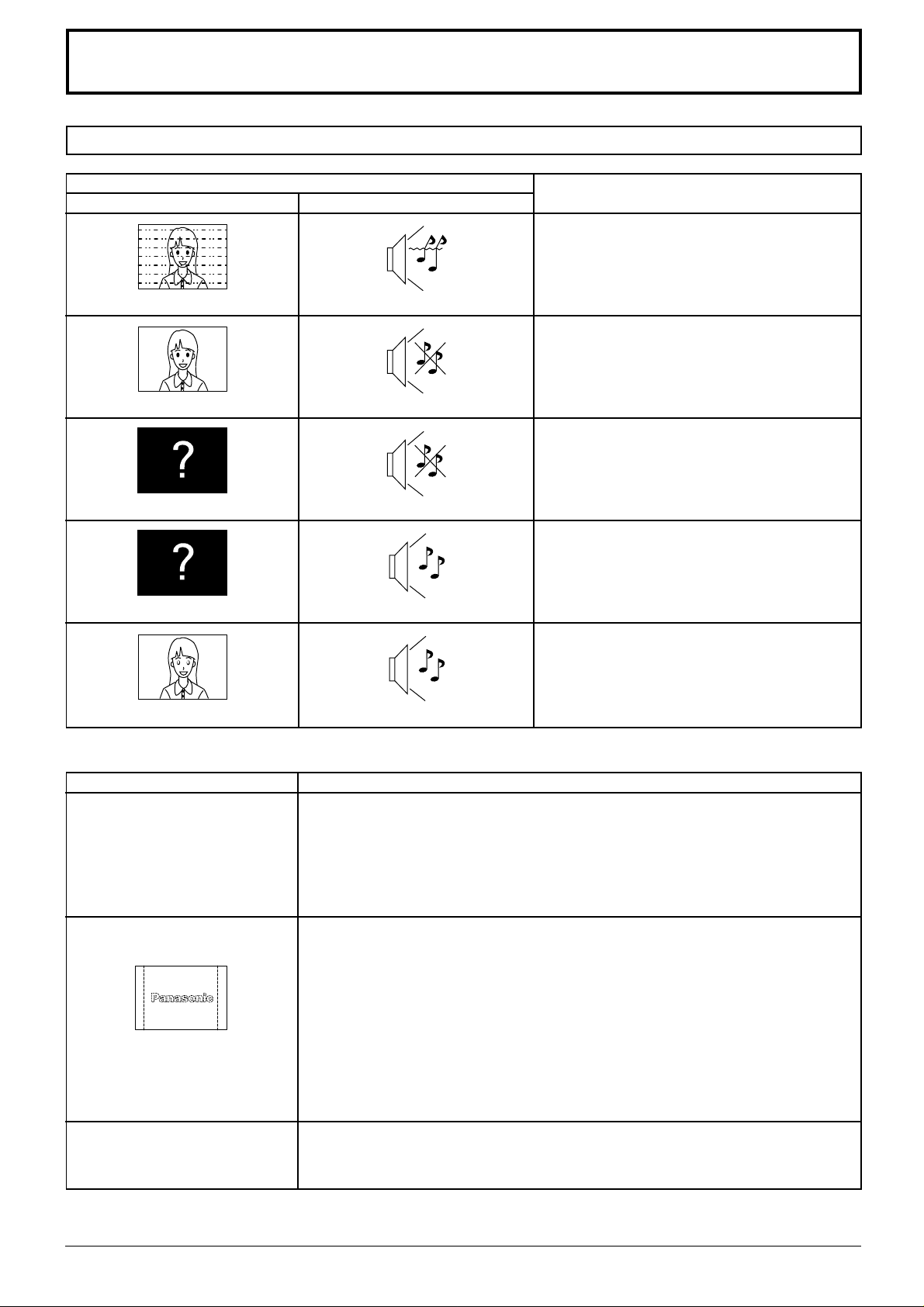
Troubleshooting
Before you call for service, determine the symptoms and make a few simple checks as shown below.
Picture
Interface
Normal Picture
No Picture
No Picture
Symptoms
Sound
Noisy Sound
No Sound
No Sound
Normal Sound
Checks
Electrical Appliances
Cars/Motorcycles
Fluorescent light
Volume
(Check whether the mute function has been
activated on the remote control.)
Not plugged into AC outlet
Not switched on
Contrast and Brighness/Volume setting
(Check by pushing the Power Switch or
stand-by button on the Remote Control.)
If a signal with a non-applicable colour
system format, or frequency is input, only
the input terminal indication is displayed.
No Colour
Plasma Display panel
Symptoms
Some parts of the screen do
not light up
After-images appear
Colour controls set at minimum level.
Colour system (see page 26, 27)
Normal Sound
Check
The plasma display panel is manufactured using an extremely high level of
precision technology, however, sometimes some parts of the screen may be
missing picture elements or have luminous spots. This is not a malfunction.
Do not allow a still picture to be displayed for an extended period, as this can
cause a permanent after-image to remain on the Plasma Display.
Examples of still pictures include logos, video games, computer images,
teletext and images displayed in 4:3 mode.
Note:
The permanent after-image on the Plasma Display resulting from fixed image
use is not an operating defect and as such is not covered by the Warranty.
This product is not designed to display fixed images for extended periods of
time.
Whirring sounds can be
heard from the display unit.
The display unit is fitted with a cooling fan to dissipate heat generated during normal
use.The whirring sound is caused by rotation of the fan and is not a malfunction.
33
Page 34
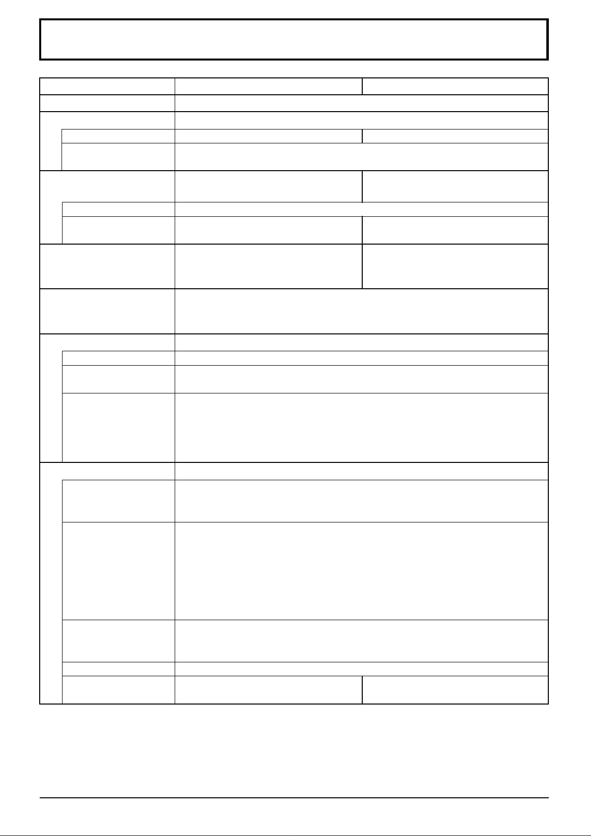
Specifications
TH-37PW4 TH-42PW4
Power Source
Power Consumption
Normal use
Stand-by condition
Power off condition
Plasma Display panel
Contrast Ratio
Brightness Capability
Screen size
Operating condition
Temperature
Humidity
Applicable signals
Colour System
Scanning format
PC signals
220 - 240 V AC, 50/60 Hz
225 W 295 W
1.8 W
1.6 W
Drive method AC type Drive method AC type
37-inch, 16:9 aspect ratio 42-inch, 16:9 aspect ratio
3000:1
(Panel only) 650 cd / m
(As a set) 330 cd / m
818 mm (W) × 461 mm (H) × 939 mm (diagonal) 920 mm (W) × 518 mm (H) × 1056 mm (diagonal)
No. of pixels No. of pixels
408,960 (852 (W) × 480 (H)) [2,556 × 480 dots] 408,960 (852 (W) × 480 (H)) [2,556 × 480 dots]
NTSC, PAL, PAL60, SECAM, Modified NTSC
525i (480i), 625i (576i), 525p (480p), 625p (576p), 750p (720p), 1125/60i, 50i,
24p, 24SF (1080/60i, 50i, 24p, 24SF) ······ SMPTE 274M
VGA display
VGA
SVGA, XGA, SXGA, UXGA (compressed)
Horizontal scanning frequency 15.5 - 110 kHz
Vertical scanning frequency 48 - 120 Hz
2
2
(Panel only) 780 cd / m
(As a set) 400 cd / m
0 °C - 40 °C
20 % - 80 %
2
2
Connection terminals
AV
COMPONENT/RGB
PC
SERIAL
SPEAKERS (6 Ω)
Video IN (RCA)
S Video IN (MINI DIN 4PIN)
AUDIO IN (RCA PIN JACK × 2)
Y/G (RCA)
PB/B (RCA)
PR/R (RCA)
HD (RCA)
VD (RCA)
AUDIO IN (RCA PIN JACK × 2)
(HIGH-DENSITY D-SUB 15PIN)
AUDIO IN (M3.5 JACK)
EXTERNAL CONTROL TERMINAL (D-SUB 9PIN)
16W [8 W + 8 W] (10 % THD) 16W [8 W + 8 W] (10 % THD)
For TY -SP37P4W -S only For TY -SP42PM3W only
1.0 Vp-p (75-ohm)
Y: 1 Vp-p (75-ohm), C: 0.286 Vp-p (75-ohm)
0.5 Vrms (high impedance)
1.0 Vp-p/composite (75-ohm)
0.7 Vp-p/non-composite (75-ohm)
0.7 Vp-p (75-ohm)
0.7 Vp-p (75-ohm)
1.0 - 5.0 Vp-p (high impedance)
1.0 - 5.0 Vp-p (high impedance)
0.5 Vrms (high impedance)
R,G,B/0.7 Vp-p (75-ohm)
HD, VD/1.0 - 5.0 Vp-p (high impedance)
0.5 Vrms (high impedance)
RS-232C COMP ATIBLE
34
Page 35
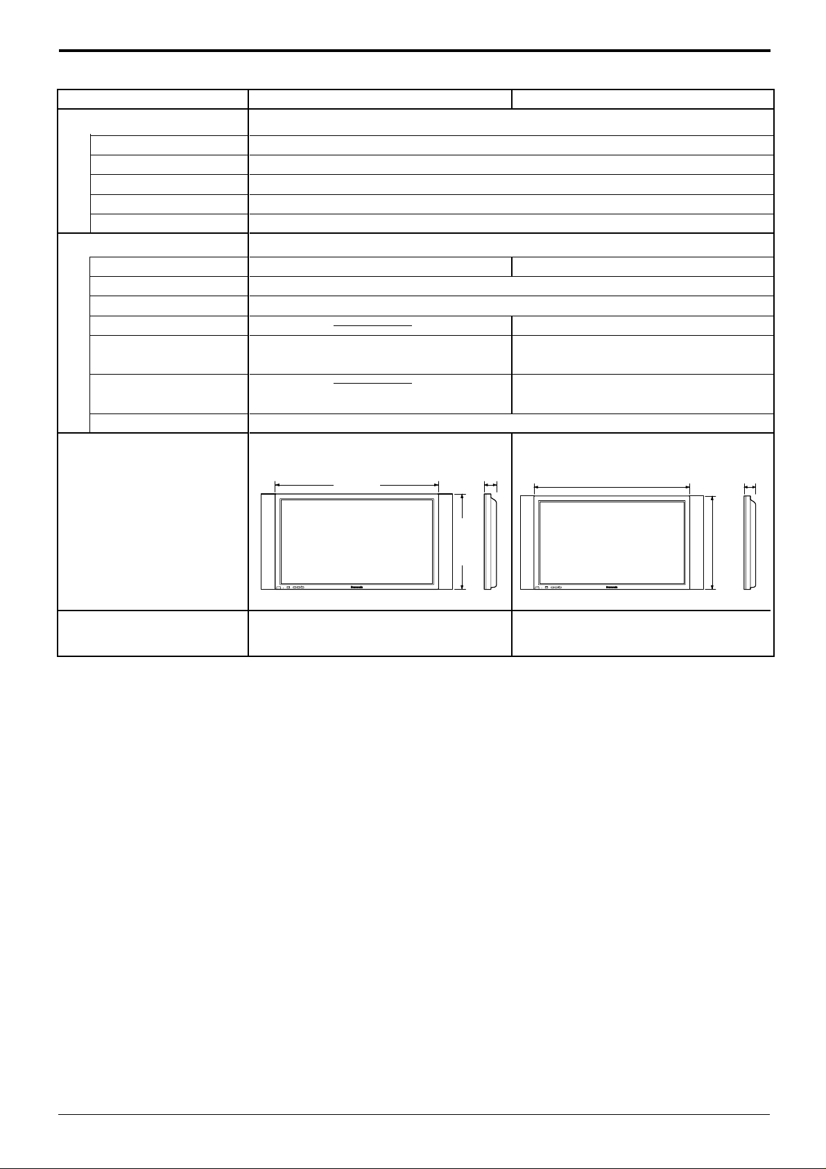
Accessories Supplied
POWER /
R - STANDBY
G POWER ON
INPUT
–
VOL
+
610 mm
1020 mm
89 mm
Remote Control Transmitter
Batteries
Fixing bands
Ferrite core
Optional Supplied
Speakers
Pedestal
Wall stand
Mobile stand
Wall-hanging bracket
(vertical)
Wall-hanging bracket
(angled)
Ceiling unit
Dimensions
(W × H × D)
Specifications
TH-37PW4 TH-42PW4
EUR646525
2 × R6 Size
TMME187 × 2
J0KF00000018 × 2
TY-SP37P4W-S TY-SP42PM3W
TY-ST42PT3-S
TY-ST42PW1
TY-ST42PF3
TY-WK37PV3 TY-WK42PV1
TY-WK42PR1
TY-CE42PS1
920mm × 550 mm × 89 mm 1020mm × 610 mm × 89 mm
1210 mm
98 mm
Mass (Weight)
724 mm
INPUT
–
VOL
+
POWER /
R - STANDBY
G POWER ON
approx. 25.0 kg net (main unit only) approx. 29.5 kg net (main unit only)
approx. 29.2 kg (with speakers) approx. 33.7 kg (with speakers)
Notes:
(1) Design and specifications are subject to change without notice. Weight and dimensions shown are approximate.
(2) This equipment complies with the EMC standards listed below.
EN55022, EN61000-3-2, EN61000-3-3, EN61000-6-2.
35
Page 36

Customer’ Record
The model number and serial number of this product can be found on its back cover. You should note this serial
number in the space provided below and retain this book, plus your purchase receipt, as a permanent record of
your purchase to aid in identification in the event of theft or loss, and for Warranty Service purposes.
Model Number Serial Number
Matsushita Electric Industrial Co., Ltd.
Web Site : http://www.panasonic.co.jp/global/
Printed in Japan
MBS0901S1091(MS)
 Loading...