

Page 1

.M
.. ;
;' i
:rj;’--i-r'?rr -'f ;^;- ■( f, ,mr V i V
J
I
Instruction manual for all the
above series of models.
Please read these instructions
before operating your set and
retain them for future reference.
TQBCC0073
This is a combined Operating
Page 2

Dear Panasonic Customer
Welcome to the Panasonic family of Customers. We hope that you will
have many years of enjoyment from your new LCD Projector.
To obtain maximum benefit from your projector, please read these
instructions before making any adjustments, and retain them for future
reference. Retain your purchase receipt also, and note down the Model
Number and Serial Number of your projector in the space provided on
the rear cover of these instructions.
Trademarks
• VGA is a trademark of International Business Machines Corporation.
• Macintosh is a registered trademark of Apple Computer, USA.
• PC-98 is a registered trademark of NEC Co., Ltd.
• S-VGA is a registered trademark of the Video Electronics Standard Association.
Even if no special notation has been made of company or product trademarks, these trademarks have been fully respected.
This Video Projector is for household use.
Page 3

Table of Contents
Warnings and Cautions
Read Before Using
Description for Each
Section
.................
• Remote Control
• Mirror Unit
• Set Stand
• Terminal Cap ...
• Projector
........
.........
..........
Turning Power On and Off
Setting Up
• Cautions During Set-Up ..........
• Cautions During Use
• Introduction of Set-Up Options
• Selecting Projection Method ....
• Placement On Floor ................
• Placement On Table................
• Mounting On Wall
• Mounting On Ceiling
..............
....................
................
Projection Distance and Location for Installing
Selecting Screen..............................................................
.
.4
Te
.... 7
....8
....8
.... 8
....9
!Ti
.. 12
.. 12
.. 13
.. 13
.. 14
.. 15
.. 16
.. 17
la
19
Projecting with the
Settings You Desire
• AV/RGB Selection
• Using With the Picture Menu
of Your Preference
Adjusting the Picture to Your Preference
System Examples
Adjustment for RGB
Input Screen
Convenient Options
for Use
Cleaning and Proper Use
Replacing the Lamp Unit
..............................................
..................................................
Cleaning and Replacing the Air Filter
• Connecting to AV Equipment
• Adjusting the Volume
• Connecting to PCs ...............
• Adjusting the Screen Position
• Adjusting the Dot Clock
• Changing Screen Display Language
• Using the Noise Timer Feature
• Using the Off Timer Feature.........................28
• Setting the Screen Colour to Blue
• Adjusting P.DE
• Automatic Adjusting of Picture Al
..................
...............
...............
...........
.........
............
...................
.................
............................................
................
.
..............
..............
............
..............
.. 20
.. 20
21
22
23
24
26
27
28
28
29
29
29
30
31
34
Monitor Display................................................................
Check Before Requesting Servicing
................................
Specifications
..............
.
..............
36
37
38
Page 4

Warnings and Cautions
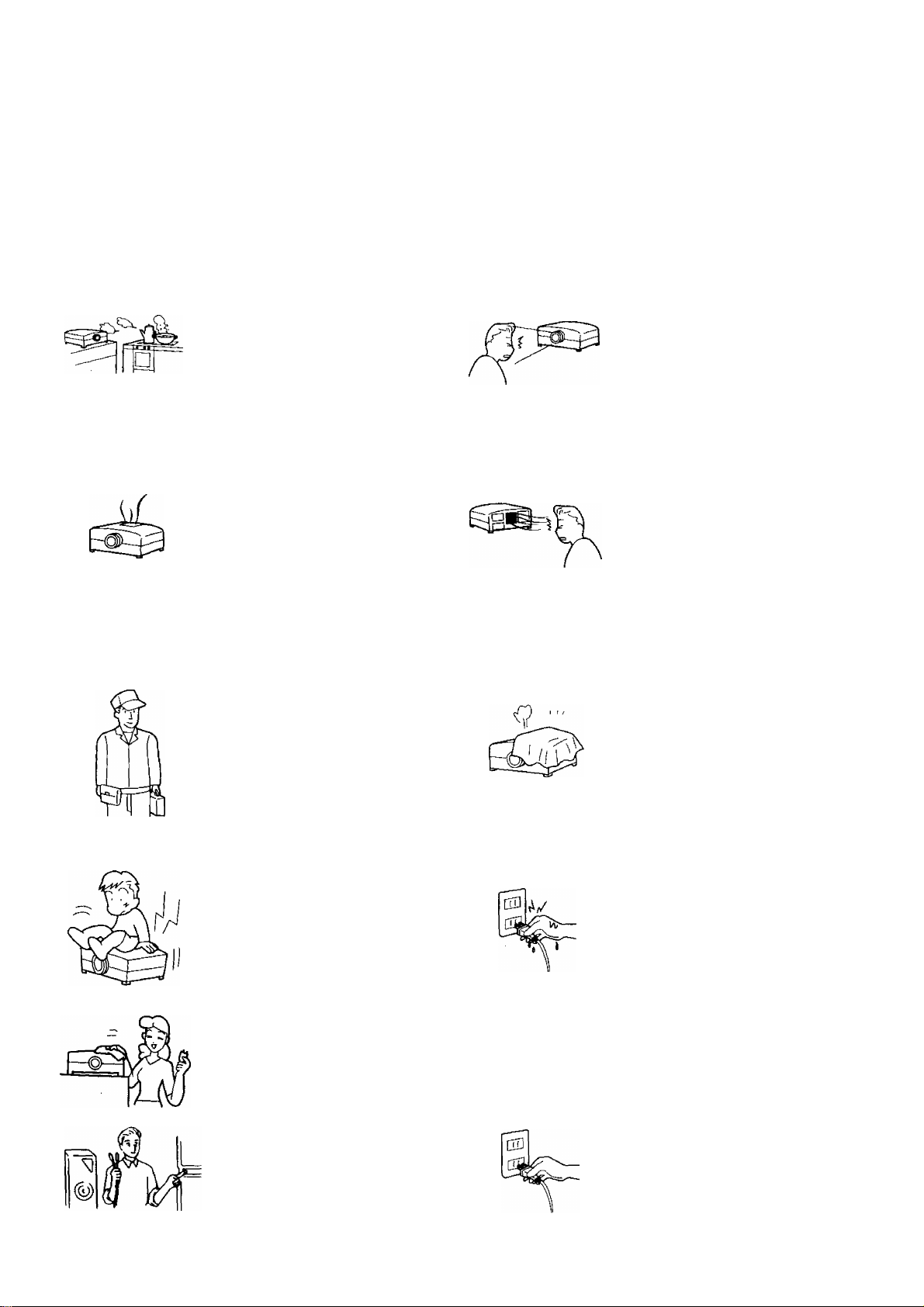
Warnings
—(g)— 5^ la
Unplug the power cord in the
event of any malfunction
(screen goes blank, no sound,
odd sounds, smoke or
unusual odors coming from
the unit).
Unplug the power cord if
foreign matter or water falls
into the unit, or if the unit is
dropped or the cabinet is
damaged.
DO NOT place any of the
following on the unit:
Flower vases, flower pots,
cups, small metal objects,
or cosmetics containers,
chemicals or water.
DO NOT insert foreign
objects (metal or easily
flammable objects).
DO NOT use this unit near
water, (near a bath tub,
etc.)
DO NOT use if the power
cord or power plug is
damaged, or if the plug
does not fit tightly into the
socket.
DO NOT use at a voltage
other than indicated.
\U
TAKE CARE NOT to
damage the power cord.
DO NOT touch this unit when
there is lightning.
DO NOT remove the top
cover as live parts and
High Voltage components
are accessible when the
top cover is removed.
DO NOT place in an
unstable location.
Page 5
Warnings and Cautions
A
Cautions
DO NOT place in humid or
dusty locations, or areas
exposed to smoke or
steam.
DO NOT place in direct
sunlight and other sources
of direct heat.
Make sure that the lamp has
cooled off fully before
replacing the lamp unit.
(Caution, High Temperature)
The lamp will be very hot
immediately after use.
Touching it can cause burns,
and objects placed in contact
with the lamp may be
deformed or damaged by the
heat.
Please ask your dealer or
installation company about
installing or attaching before
attempting to do so
(depending on the type of
residence you have, certain
types of installation may not
be possible).
DO NOT look into the
projection lens when the
projector is in use.
The projection lens emits
strong light. Looking into
this lens may damage your
vision.
Be careful of hot air being
expelled from the air exhaust
vent.
The air exhaust vent expels
hot air. Do not place your hand
or face in front of this vent as
you may be burned. Also do
not place objects sensitive to
heat near this vent, as they may
be damaged or warped by the
hot air.
DO NOT OBSTRUCT
VENTILATION HOLES.
Excess internal heat may lead
to fire or damage to the unit,
Please observe the following:
•Do not place it in confined
spaces such as cabinets
or bookshelves.
•Do not coverit with sheets.
Do not place it on carpets or
mattresses.
DO NOT stand, or place
heavy objects on the unit.
Particular care should be
taken by families with small
children.
Before cleaning, unplug the
power plug from the socket.
Turn the power “Off" before
connecting other electrical
equipment.
DO NOT touch the power plug
If your hands are wet.
Unplug the power plug from
the socket if you are not going
to use the unit for an Extended
period.
Hold the plug by hand when
unplugging it from the wall
outlet.
Page 6

Read Before Using
Effective Distance for Operation Using the Remote Control
View From Directly
Above
View From the Side
The remote control must be within 7 m of the optical receiver in order to operate the unit.
Shining strong light on the optical receiver of the projector may interfere in transmission between the remote
control and the receiver, and prevent the remote control from operating properly.
Inserting the Battery
Open the cover
O
Apply slight downward
pressure while pulling
towards the bottom.
@
Put in batteries and close the cover
Insert the batteries ensuring cor
rect polarity.
This is identifiable by the V' and
symbols on both the batteries
and inside the battery
compartment.
Replace the cover.
Two R6 (AA) size
Caution
To prevent damage or leaking
from the batteries:
• Do not mix different types of
batteries or new and old batteries,
and do not use rechargeable
batteries (Ni-Cd)
They are different in shape and
performance and may fail to
ensure correct operation.
• The batteries cannot be
recharged.
• Do not mix the batteries in with
the burnable trash, or burn or
disassemble the batteries.
Page 7
Description of Each Section
The circled numbers listed (example ) indicate the page on which the explanation of that section begins.
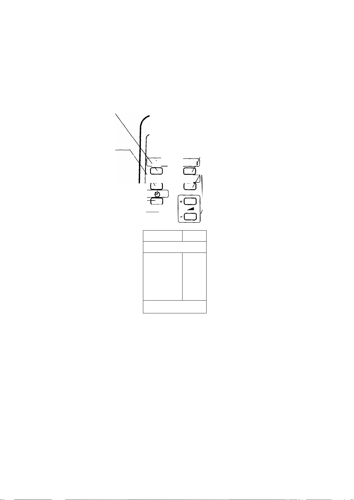
Remote Control
Power Button
Turns the power on and off
when the main power switch on
the unit is on.
Recall Button
Used to confirm the input
mode and settings. The
Screen Display Mode will turn
on briefly, but will disappear
after several seconds.
------------------
Panasonic
LCD PROJECTER
~1 Cav/RG[
Ll
AV/RGB Switching Button
Switches the input signal
Mute Button
Turns off the volume for the
video input {AV1, AV2).
Volume Buttons
Adjust the volume for the
internal speaker at video input
mode.
OFF Timer Button
Turns the power off automatically.
Al Button
Automatically adjusts the picture
for video input mode.
MENU Button
Turns the menu display
on the screen on and off.
----------------------------
-----------------
-----------------------
Normalisation Button —
Sets the "Picture Adjustment,"
and the "Screen Position
Adjustment,” etc. to their Normalisation
settings.
( Al 1
o
MENU II N
-OgDCZD
----------
----------
A.
▼
CD
PICTURE
►(_)
Picture Menu Button
Switches the picture menu.
Cursor Buttons
Used to select, adjust and set
menu items on the menu
screen.
• Please take care not to drop the remote control.
• Please take care to prevent the remote control from coming into contact with liquids.
• The projector can also be operated by the power, input-switch, menu, cursor, and volume buttons on the main
unit.
Page 8
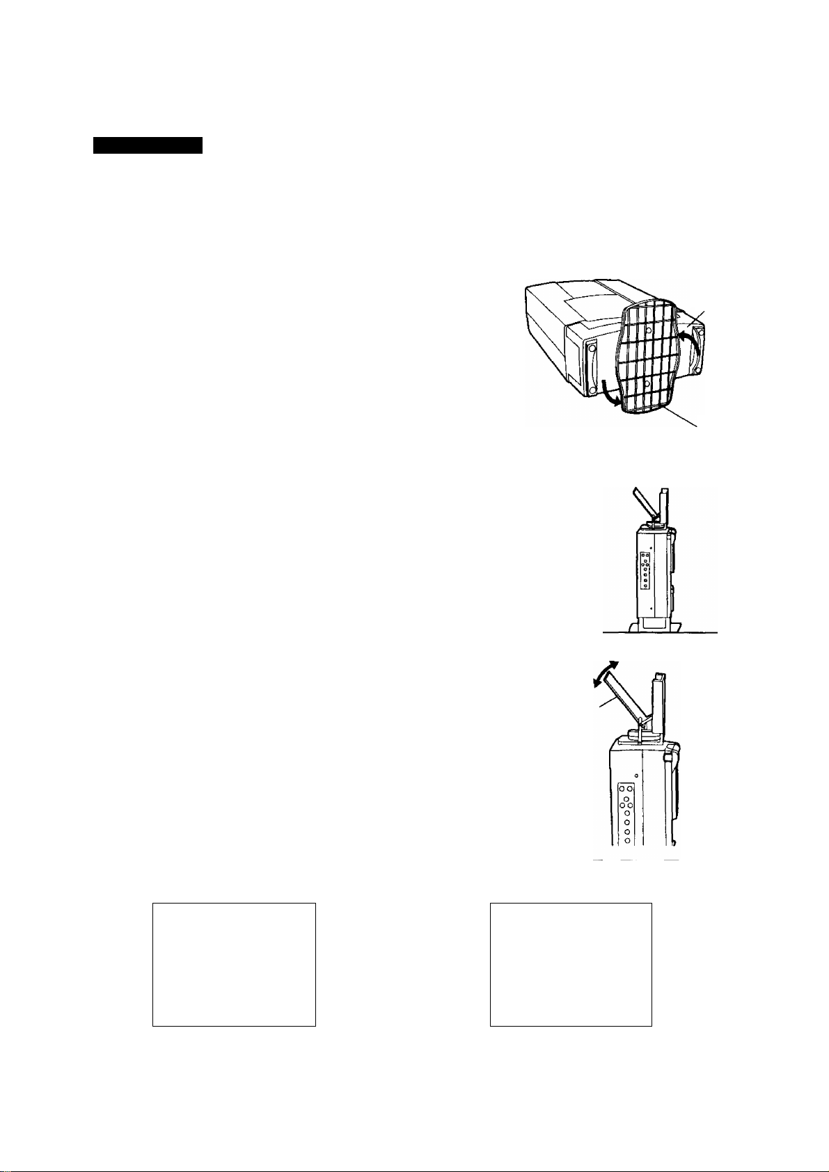
Description of Each Section
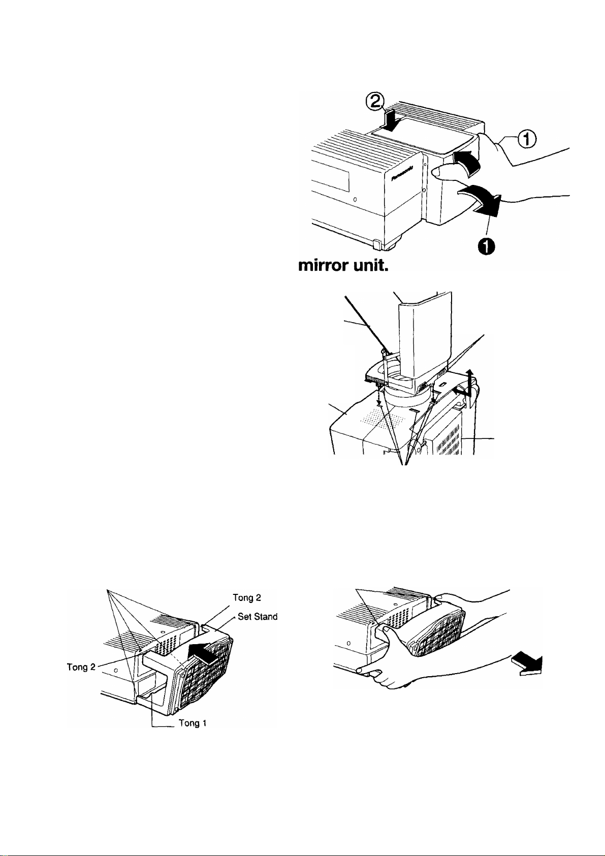
■ Drawing in and out the mirror unit.
The mirror unit can be folded up and stored
when not in use.
Drawing out
Drawing in
OPlHI out the cover section, and
adjust the mirror angle for use.
CJ) Press the cover in to draw it in.
d)Press the mirror in to draw it in.
Attaching and removing the
Removing
Attaching
Pull out after sliding the mirror
unit towards the bottom of the
main unit.
Press until the attachment
knobs on the mirror box slide
into the attachment slots on the
main unit, and lock with a click. Front Side of
Mirror
the Unit
Lock button (2 places)
I The lens cap cannot be put on with the mirror
unit attached.
Attaching and Removing the Set Stand
Attaching
Slide the set stand into the attachment slots on the
unit, and push in until the stand locks with a click.
When setting up the set stand, insert tongs 2 after
inserting tong 1.
Main Unit Attachment Slots (4)
Bottom Side of the
Unit
Attachment Slots (6)
Removing
Press on the two spots above the set stand to unlock,
and pul! back to remove.
Press
8
Notes on attaching the terminal caps
The terminal caps (included as standard) on the back terminal section are for the purpose of preventing dust from falling
into the terminal section. Please attach these caps to those terminals that are not connected to cables.
Page 9
Description of Each Section
The circled numbers listed (example (^) indicate the page on which the explanation of that section begins.
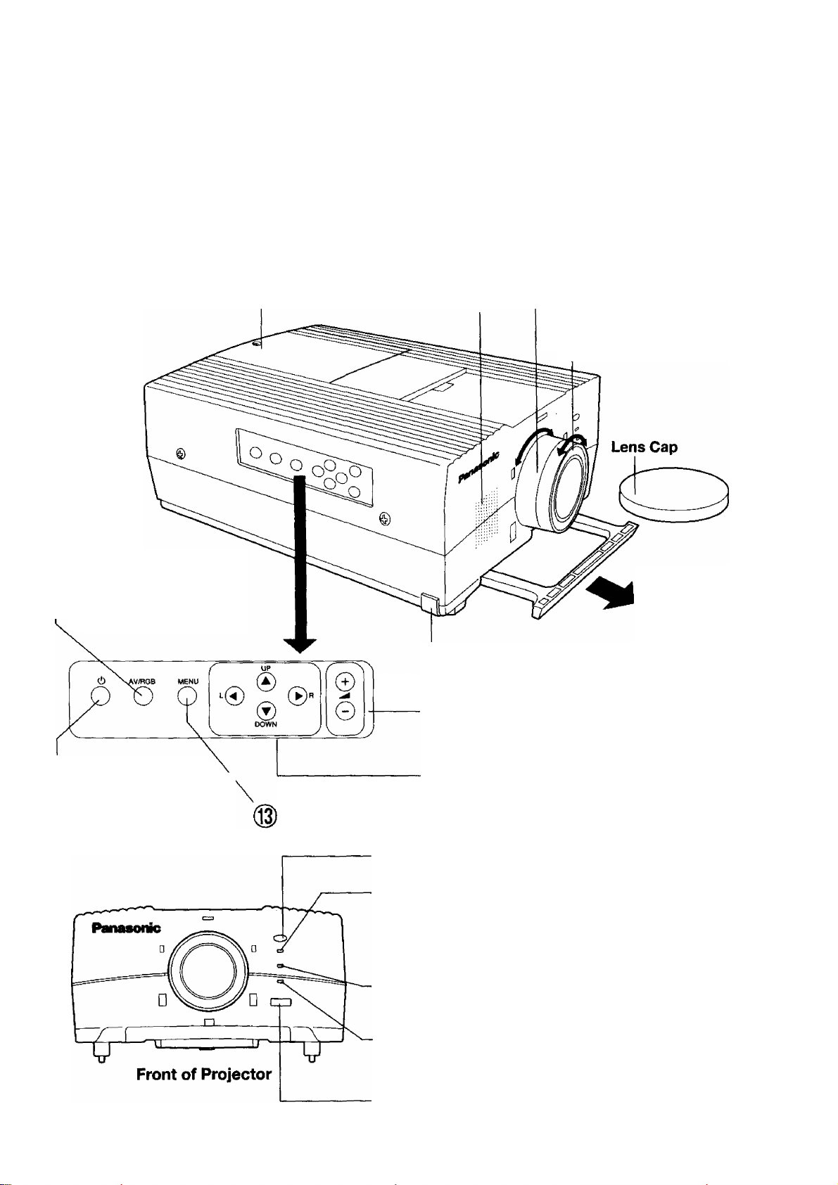
Projector
<Operating panels on Top, Front and Side.>
Lamp Unit Storage Bay
Stores the Lamp Unit
AV/RGB Switching
^ Button
Switches the signal being
projected each time the button
is pressed.
Speaker Section Zoom Ring
(Monaural) Rotate the zoom ring to adjust
Stores one (1 W) Speaker the screen size.
Focus Ring
Rotate the focus ring to
adjust the focus.
Carrying Handle
Use when carrying
and taking out of
handle.
Adjuster Button
m3/ Used to adjust the tilt of
the projector.
^ Power Button
M-V When the main power is orv
this button turns the power
on or off.
/^Volume Button
Adjusts the internal speaker volume
at video input mode.
Cursor Button
m3/ Use to select, adjust and set the menu screen options.
Menu Button
Turns the menu display on the screen on and off.
Optical Receiver for Remote Control
Optical Receiver for the signals from the Remote Control.
Power Display Lamp
©
This lamp illuminates in red when the main power switch is ON,
and in green when the power switch on the remote control is ON.
It flashes in green on and off for about 2 minutes when the cooling
fan is running after the power has been turned off.
^ Lamp Monitor
Turns on when it is time to change the lamp unit, and flashes on
and off when the lamp circuits are not functioning properly.
Temperature Monitor
Reports abnormal temperatures in the projector by turning on or
flashing on and off.
Main Power Switch
Turns the main power ON and OFF (when the power is turned on,
the projector enters stand-by mode.)
Page 10
Description of Each Section
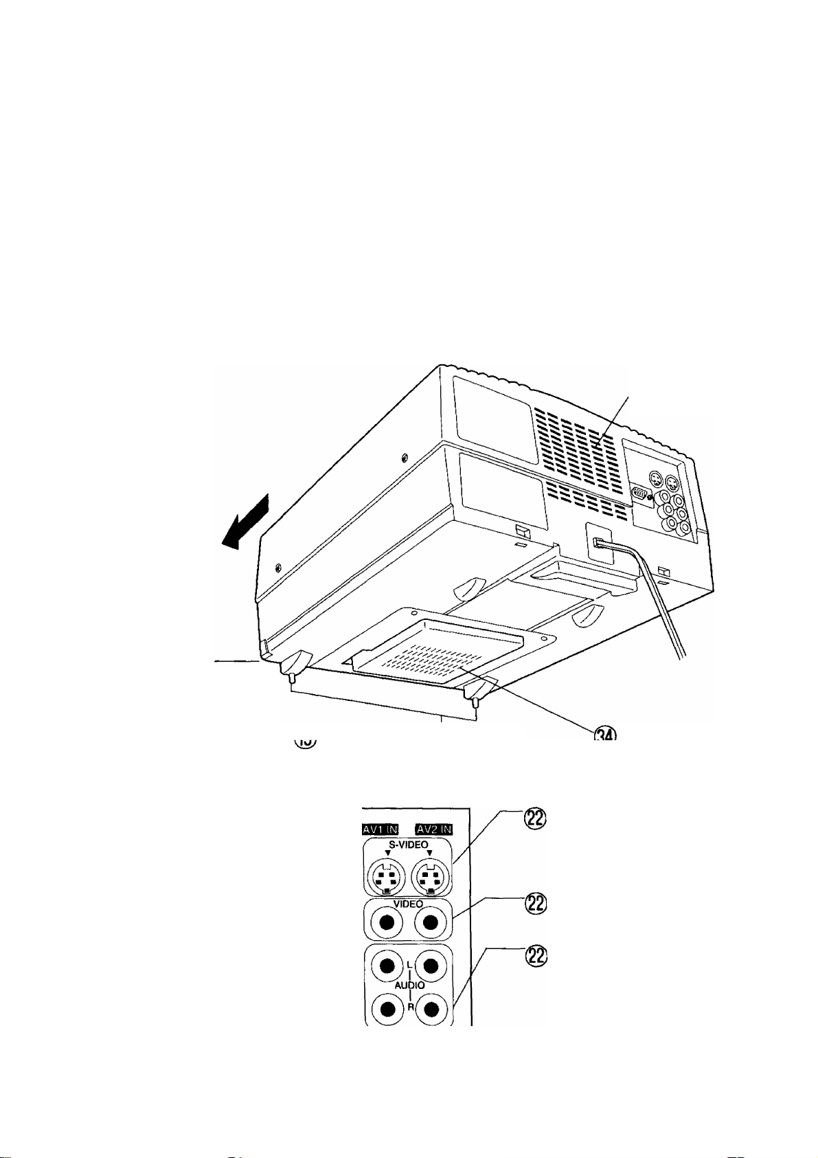
<Bottom and Back>
Caution
Be careful of hot air flowing out of the air exhaust
vents.
Your hand or face might suffers form burns if you
being them near the ventilation holes. Objects if
A
placed near these holes are liable to be deformed.
Air Exhaust Vents
Front
Adjuster Button
Used to adjust the tilt of the
projector.
<Back Terminal Section>
RGB input Terminal
Inputs the RGB signals
(PC picture signals)
(D sub-pin 15 input).
10
© <§>
Adjustable tegs.
Used to adjust the tilt of the projector.
RGB IN
Air Filter Section
S-Video Input Terminals
Input terminal for the S-Video Signals
The S-Video takes priority when both
video input terminals are connected at
the same time.
I Video Input Terminals
These are the input terminals for the
video signal.
, Audio Input Terminals for Video
Input
These are the audio input terminals that
correspond to the S-Video and Video
Signals Since the projector has an
internal monaural speaker, audio signals
input in stereo (left and right) are
combined in the projector into a
monaural sound.
Page 11
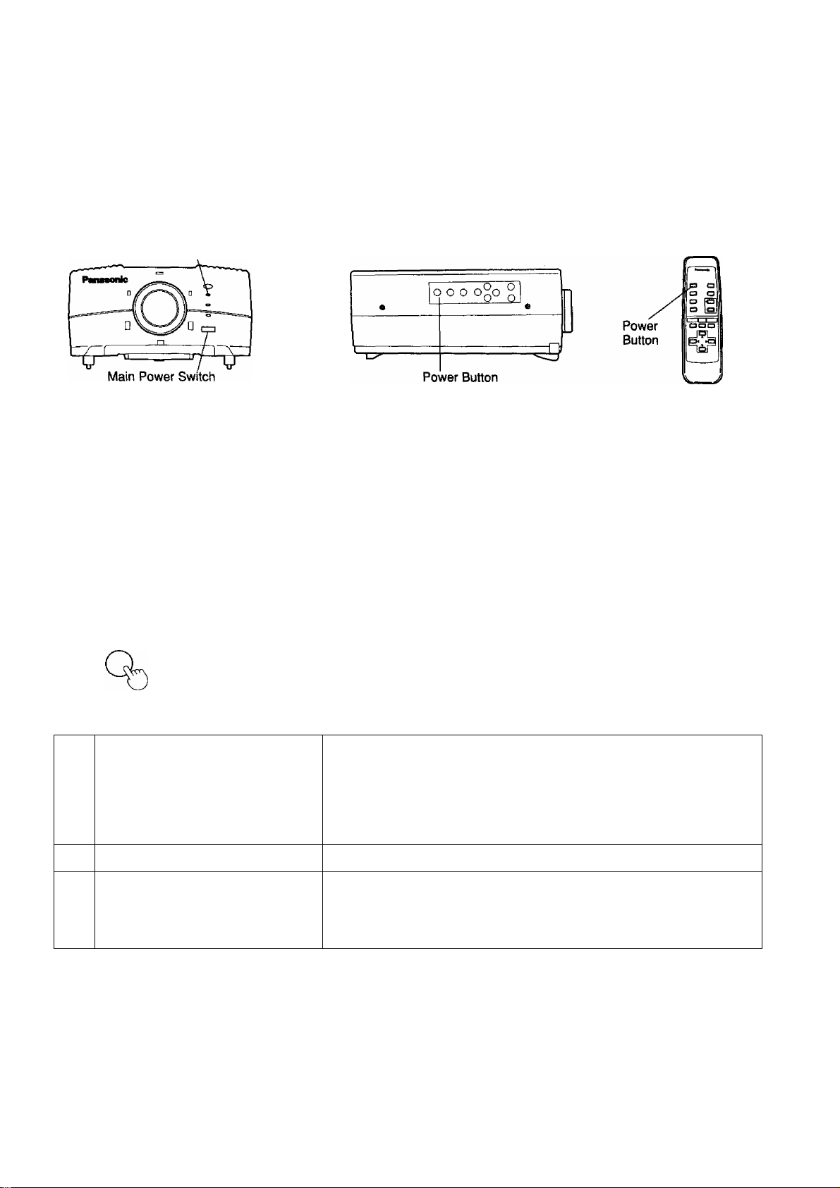
Turning the Power On and Off
Turning the main power switch off while the cooling fan is still running will reduce the life of the projection lamp.
Always follow the following procedure when turning the power on and off.
Front of Projector
Power Display Lamp
■Preparation
Plug the power cord into the wall socket.
■Turning On the Power
Turn on the Main Power
_o|
_
=t)
OR
o
(Projector)
Turn on the Power
(Projector) (Remote Control)
tb
Side Operating Panel on Projector
Turn on the Main Power Switch on the front of the projector.
The Power Display Lamp will shine red, and the unit will switch to stand-by
mode.
Press the Power button on the operation panel on the side of the projector,
or press the Power button on the remote control.
The Power Display Lamp will shine green, and an image will be projected
onto the screen. (A few seconds will be required before the lamp achieves
sufficient brightness).
Remote Control
Turning off the Power
Turn Off the Power
(Projector) (Remote Control)
o
6 Uj
Wait until the cooling fan turns off.
Turn off the Main Power.
(Projector) 1
• The cooling fan will continue to run even after the power is turned off, while the internal temperature of the
projector remains hot (approximately 120 seconds). Please do not unplug the main power cord or turn off the
main power switch while the cooling fan is still running.
• If you accidentally turn the power off during use, the images may not be projected even if you immediately turn
the power back on. Wait until the projection lamp cools, and then turn the power back on.
• The lamp may not turn on immediately after the power is turned on. If this happens, the lamp will turn on again
automatically after 30 seconds (during this time the Power Display Lamp”s LED illuminates in green.) If the
lamp does not light up again, the Power Display Lamp’s LED flickers in green, and the Lamp Monitor Display’s
LED flickers in red, turn on the power after the lamp has cooled down sufficiently.
• The projector uses approximately 5 W of power even in standby state after the power has been turned off and
the cooling fan has stopped.
01
Press the Power button on the operation panel on the side of the projector,
or press the Power button on the remote control.
Mr
Power display lamp will flash in green on and off.
Wait until the Power Lamp a red light on (approx. 120 seconds)
Turn off the Main Power Switch on the front panel of the Projector.
Mr
The power will turn off, and the Power Lamp will turn off after 6 seconds.
11
Page 12

Setting Up
Cautions During Set-Up
Please make sure to obey the following when setting up the projector.
• Please do not set up the projector in locations subject to vibration or shocks.
Vibrations and shocks can damage the Projector and cause it to malfunction.
Please set up the projector in a location that is not exposed to vibrations or shocks.
• Please do not set up the projector near high voltage wires or power sources.
Setting the projector up near high voltage wires or power sources may cause interference with the operation of the
projector.
• Please do not set up the projector on top of a tablecloth or carpet.
This may interfere with circulation to the air filter and cause the internal temperature of the projector to rise, which will
cause the protection circuit to operate and cut off the power.
• If you intend to mount the projector on the ceiling or a wall, please discuss this
with the dealer from which you purchased the projector.
Cautions During Use
To display the highest quality in images;
Do not shine external light or illumination on the screen surface. This will prevent you from seeing high contrast and high
quality images. Cover windows with curtains and blinds, and turn off fluorescent lamps near the screen surface. Moreover,
flooring or wails that reflect lights should be covered by carpets or wallpaper.
Do not touch the projection lens or the reflecting surface on the mirror section
with your bare hands.
Fingerprints or dust on the projection lens surface will be magnified and projected on the screen. Therefore please do not
touch the lens or mirror surface with your hand. If the projector is not being used, the lens should be covered with the lens
cap, and the mirror unit section should be folded and stored.
*The lens cap cannot be put on with the mirror unit attached.
• Do not hang on objects or a step-ladders on it.
The unit may drop which may lead to injuries.
12
Page 13

Setting Up
■ Please choose the installation that suits your room and
your desired purposes.
1.Using a Table (see p. 15)
S.Mounting on the wall (see p. 16)
2.Placement on the floor (see p. 14)
*Use the Mirror unit and setting stand.
4.Mounting from the Ceiling (see p. 17)
Please select the projection method that matches the installation.
(The default setting at shipment is for placement on the floor).
Preparation
Turn on the power, and use the AV/RGB switching button to select AV1, AV2 or RGB input.
Example RGB Input
O
@
Press the MENU Button
Use the a or ▼ buttons to
select the “SETTING" Menu.
Press the 4 or ► buttons to select the
“SETTING” Menu Screen.
Press the a or ▼ buttons to select the appropriate Setting 1 through 4, that
matches your installation.
PICTURE
SIGNAL MODE
POSITION
SETTING
CLOCK
FEATURES
LANGUAGE
1
SETTING 2
3
4
&
Press the MENU Button twice to complete.
SETTING 1
SETTING 2 Floor Placement
SETTING 3
SETTING 4 Celling Mount
For Use on a Table
Wail Mount
Left and right reversed from Setting 2,
Default setting at shipment.
Left, right, top and bottom reversed from setting 2.
Top and bottom reversed from Setting 2.
13
Page 14
Setting Up
(Please see page 18 concerning the projection distance and location for installing.)
Using when placed on the floor.
Preparation;
Place the projector on the floor, and use the mirror unit and setting stand to stand the projector upright.
Adjustments
Grasp the centre of the Set Stand with your hands, and rotate 90
degrees as shown in the diagram at right, until the cover locks with
o
a click.
Attach the mirror unit and the setting stand (see p. 8)
^CautloTK
In case of placement on floors,
please use fall-prevention
panel.
O
Malfunctions or injuries are liable to be caused if the unit falls down.
Set Stand
Fall prevention
panel
@
Stand the Projector on the Floor.
Adjust the mirror angle so that the picture
shines on the centre of the screen.
Mirror
• Please refer to the measurements on page 18 when setting up the projector.
Setting the projection settings. Please see page 13 for details.
14
O
PICTURE
SIGNAL MODE
POSITION
SETTING
CLOCK
FEATURES
LANGUAGE
SETTING 2
1
3
4
Select "SETTING 2"
Page 15

Setting Up
■Placement on a table.
Preparation:
Unless the projector is placed flat, you will not be able to see clear images without distortion.
If you are placing the projector on a table, please make the following adjustments to make sure that the stand is not off
balance.
Adjustments
Lift the front of the projector until it is flat. While
holding the projector in this position, press the two
o
adjuster buttons at the bottom of the projector.
The setting legs (left and right) will extend until they
come into contact with the setting surface.
• Please do not let go of the projector until both
of the setting tegs on the left and right of the
projector come into contact with the setting
surface.
Letting go of the projector.
When you let go of the adjuster buttons, the adjusting function will be locked.
Remove the mirror unit and the setting stand (see page 8)
Until 33mm
Adjustable leg
Adjuster button
@
To Retract the Setting Legs.
Lift the projector slightly up and press on the adjuster buttons. While pressing these buttons, gently let the
projector down.
Please do not press the adjuster buttons unless you are supporting the projector with your hands.
Releasing the lock and letting the projector fall abruptly onto the stand may break the projector.
Setting the projection method.... Please see page 13.
PICTURE
SIGNAL MODE
POSITION
SETTING
CLOCK
FEATURES
LANGUAGE
SETTING 1
2
3
4
Select “SETTING V
15
Page 16

Setting Up
(Please see page 18 concerning the projection distance and iocation for installing.)
Mounting Projector on Wall
Preparation:
Please use the included fittings when mounting the projector on a wall.
Please follow the included installation Manual for Wall mounting, and request a specialised wall mounting technician, to install
the projector properly.
Attach the mirror unit and setting stand (see page 8).
Example of mounting on wall.
• Selecting the Projection Setting ... Please see page 13 for details.
PICTURE
SIGNAL MODE
POSITION
SETTING
CLOCK
FEATURES
LANGUAGE
1
2
SETTING 3
4
Select "SETTING 3”
16
Page 17

Setting Up
I Mounting Projector on Ceiling
Remove the mirror unit (see page 8).Preparation:
The Ceiling Mount Kit TY-CE1 is required to mount the projector on the ceiling. Please discuss this with the
dealer from which you purchased the projector.
Example of mounting on ceiling.
Selecting the Projection Setting - Please see page 13 for details.
PICTURE
SIGNAL MODE
POSITION
SETTING
CLOCK
FEATURES
UNGUAGE
1
2
3
SETTING 4
Select “SETTING 4”
17
Page 18

Projection Distance and Location for Installing
Please refer to the following diagrams to determine the projection location.
Side View
A -- Effective Height of Screen
B -- Effective Width of Screen
H - Height from projection centre (D
Top View
to the screen’s upper edge.
• The minimum projection distance is 1.2 m. Please place the projector at least 1.2 m from the screen.
• The sizes of the images projected will differ slightly depending on whether the input is video or RGB. Please adjust
using the zoom function.
• If the screen size is reduced slightly, the image will be brighter.
[During Video Input]
Projection
screen size
(Type)
40 610
50 762
60 914
70
80 1219
90 1372
100
150 2286
200 3048
Screen Size (mm)
Effective Height (A) Effective Width (B)
813 Approx. 570 Approx. 1,6m
1016 Approx. 710 Approx. 2.1m
1219
1067
1524
1422
1626 Approx. 1140 Approx. 3.3m
1829
2032
3048
4064
Height from
projection centre (a)
to the screen’s
upper edge.
H (mm)
Approx. 860
Approx. 1000 Approx. 2.9m
Approx. 1280
Approx. 1430
Approx. 2140 Approx. 6.2m
Approx. 2850
Projection Distance (L)
(Screen surface Lens surafce)
Shortest
Approx. 2.5m
Approx. 3.7m
Approx. 4.1m
Approx. 8.3m
Longest
Approx. 2.2m
Approx. 2.7m
Approx, 3.3m
Approx. 3.9m
Approx. 4.5m
Approx. 5.1m
Approx. 5.6m
Approx. 8.5m
Approx. 9.0m
18
Page 19

Selecting Screen
A screen is needed to view images from the projector. The brightness and viewing range may vary depending on the type of
screen used.
When selecting a screen, please consider the features of the screen carefutly, and select a screen that fits the location where the
screen is to be used.
(Reference) Screen Features
Type of Screen
White Screen
Silver Screen
Screen Features
Can be viewed from any direction within
the viewable area. However, clear images
cannot be seen unless the room is
darkened like a movie theatre.
Images are reflected off of the screen at 24 times the brightness of a white screen.
Various screen manufacturers sell various
types of screens, that offer differing
brightness ranges. Some screens also
restrict the viewing angles.
*Well suited to ceiling or wall projection.
Similar to a silver screen, except that
images are reflected back in the same
direction from which they were sent.
*WelI suited to projection when the
Bead Screen
Type 80 and Type 100 bead screens are sold separately.
Type 80
Type 100
projector is to be placed on a table stand
or floor stand.
TY-SC80S {with speakers)
TY-SC80N
TY-SC100N
19
Page 20

Projecting With the Setting You Desire
AV/RGB Selection
(Projector) (Remote Control)
To switch inputs press the AV/RGB switching button on the projector, or the
remote control. Inputs will be switched in the following order:
OR
Signals from the device connected to
AV1 Input will be projected.
Please do not connect cables to the S-Video Input Terminal if you wish to project a video signal from the video
input terminal.
At the time of shipment, the default colour projection for Auto or RGB input is set to Auto. If the images are not
being projected correctly, however, it may be necessary to change the setting to match the input signal.
Piease see p. 23 for selection of colour standard for the video input signal. Please p. 25 for selection of mode
for the RGB input signal.
Signals from the device connected to Signals from the device connected
AV2 Input will be projected. to the RGB Input will be projected.
I i.
Using with the Picture Menu of Your
Remote Control Pressing the Picture Menu Button on the remote control wilt switch
Standard picture Soft Picture Bright Picture
• The selected Picture Menu will be memorized for each input switching.
• The contents of the Picture Menu (colour, contrast, etc.) let you make the desired changes. (See page 21,
20
Page 21

Adjusting the Picture to Your Preference
The picture can be adjusted to your preference for each AV/RGB setting selected for the projector using the method discussed on
p. 20 (adjustments will be stored for each of Pictures 1 through 3). The options that can be selected will differ between the Video
(S-Video) signal and the RGB signal. The adjustment procedures presented below are explained on the screen when inputting the
Video (S-Video) signals.
o
@
o
@
Press the MENU Button.
Select the “PICTURE” menu with the
buttons.
Set with the < and ► buttons.
Press the remote control “PICTURE MENU"
button, and select the picture menu you want
to adjust.
Select the “COLOUR” with the 4 and ► buttons.
Press the 4 and ► buttons to adjust.
Press the "MENU" Button twice to complete
(screen returns to the normal viewing condition).
• The buttons you press and the adjustments made will differ depending on the adjustment setting. Please refer to
the following table.
and
PICTURE
COLOUR SYSTEM
SETTING
FEATURES
UNGUAGE
PICTURE 1
COLOUR 32
NTSC-TINT
BRIGHT
CONTRAST
SHARPNESS 32
COLOUR TEMP STD
PICTURE 1
COLOUR
NTSC-TINT
BRIGHT
CONTRAST
SHARPNESS
COLOUR TEMP STD
COLOUR
35 H
32
32
63
32
32
32
63
32
Press the "N"
button to
return to the
normalisation
setting.
Adjustment
Item
COLOUR
NTSC-TINT
BRIGHT
CONTRAST
SHARPNESS
COLOUR TEMP 4>
• Press the “MENU” Button to close the Adjustment Screen or Main Menu Screen.
• NTSC tint can not be adjusted for the colour systems SECAM and PAL.
• The selected colour temperature can be stored in the memory, however, it would be the same even if the input is
switched over. 21
Button
►
4
►
4
►
4
►
4
►
4
Increases the Colour
Lightens the Colour
Adds a Green Tint to Flesh Tones
Adds a Purplish Red Tint to Flesh Tones
Brightens the picture
Makes the picture darker
Makes the screen brighter and the picture darker
Makes the screen darker and the picture brighter
Increases the sharpness of the picture quality
Makes the picture quality softer
STD -Standard
Warm-Adds a reddish hue to the screen.
Cool-Adds a bluish hue to the screen.
Adjustment
Extent of
Adjustment
Maximum
Value 63
Minimum
Value 0
Maximum
Value 63
Minimum
Value 0
Maximum
Value 63
Minimum
Value 0
Maximum
Value 63
Minimum
Value 0
Maximum
Value 63
Minimum
Value 0
Remarks
Of^ operational during video
signal input (including S-Video).
Only operational during
NTSC3.58/NTSC 4.43 video signal
^(including S-Video).
Only operational during video
sigrial input (Induding S-Video).
Page 22

System Examples
Remarks on System Installation
• Please read the User Manuals carefully for any equipment you intend to connect to the Projector.
• Make sure that the power is off for each piece of equipment before connecting any cables.
• If the included cables cannot be attached because of the location in which the projector is installed, please use
commercially sold cables that match the equipment to be connected.
• The signals that can be connected to the projector are video signals, S-Video Signals and Analog RGB Signals (with
synchronous signals of 0.6 - 8.0 Vp-p).
• The projector has one 1 W internal speaker. A separate audio system would be required to output high volumes, or to
enjoy stereo sound (please connect each device directly to the audio system).
• Some computer models cannot be connected to the Projector,
Connecting to AV Equipment
Video
12
• The S-Video In terminal will have priority when cables are connected to both the S-Video In and the Video In
terminals. Please do not connect a cable to the S-Video In if you wish to project video signals.
• If the video signal is to be connected using a BNC plug cable, please use a (commercially sold) BNC-Pin Adapter
if you wish to convert to a pin jack.
• The left audio and the right audio for the Video Input are combined within the Projector into monaural audio.
Page 23

bystem Examples
Selecting the Colour System for Video (S-Video) Input
Please use the following procedure to select the Colour System if the signal does not match and a normal picture is not
projected when selecting AV1 or AV2 during input switching. Normally the Projector can be used as is without this setting, since
at the time of shipment the Projector is set to Auto.
SettinQ Procedure (Either the Remote Control or the Projector can be used to set the Colour System)
O
@
Press the MENU Button, and use the a and ▼ buttons to select
the “COLOUR SYSTEM" menu. Then use the 4 and ► buttons to
execute.
Use the ▲ and ▼ buttons to select the Colour System that
will yield the proper image.
Press the MENU Button twice to complete.
• NTSC3.58, NTSC4.43, SECAM and PAL are television broadcast system. This Projector can project
video signals that correspond to these system.
• In some cases images will not be properly displayed under the Auto setting, if the picture is poor,
including dubbing tapes. Switching the Colour System is an effective measure to take in these instances.
PICTURE
COLOUR SYSTEM
SETTING
FEATURES
LANGUAGE
AUTO
NTSC 3.58
NTSC 4.43
SECAM
PAL
Adjusting the Volume
Use the volume adjustment buttons {-/+) to adjust the volume during video input.
Press + to increase the volume.
Press - to decrease the volume.
• Even if another screen is being displayed, these buttons will operate when
pressed, although the adjustment level will not be displayed.
• The buttons will not operate during RGB signal input.
Turning Off the Volume
Pressing the Mute button “o” during video input will cause the sound to turn off and the Mute
indication to be displayed as shown right.
Press the Mute button again to turn off the Mute indication. The sound will return at its prior
volume, and the volume level will be indicated for approximately 3 seconds.
• Even if another screen is being displayed, the Mute button will operate when
pressed, although the Mute indication will not be displayed.
• The settings will be cancelled by turning off the power, or by pressing the
volume “+” button.
• The Mute button will not operate during RGB signal input.
23
Page 24

System Examples
Connecting to PCs
PC
—To Video Output Terminal
S Some PCs require commercially sold RGB signal
* conversion adapters.
N
RGB cable
r
-------
(0>
s
____________
RGB IN
f ooooo 1
\ ooooo/
\ooooo ;
D-sub 15p
Back of Projector
------------------V
• lease refer to the data presented on page 25 concerning PCs that can be connected
to the Projector. In some cases other PCs may not work with this projector.
• There is no audio signal in RGB input.
• Some PC models cannot be connected to the Projector.
• A commercially sold adapter is required to use the included RGB cable (D-sub 15P)
to connect a PC-98 series computer (which has a D-sub 15P terminal) or a Macintosh
computer to the projector.
There is no need to use an adapter for computers with DOS/V compatible D-sub 15P
terminal.
Signal Names for D-sub 15 Connector
Pin No. Signal Name
©
(D
(D
R
G
B
GND (Ground)
GND (Ground)
Pin No.
®
@
®
@
Signal Name
GND (Ground)
GND (Ground)
GND (Ground)
NC (not connected) VD
GND (Ground)
24
(D®@® ©
® ®® @®
Pin Layout for RGB Input Terminal
Pin No.
®
®
©
Signal Name
GND (Ground)
NC
HD/SYNC
NC (not connected)
Page 25

System Examples
Selecting the Signal Mode for RGB Signal Input
The Projector is set to Auto, which will automatically select the Signal Mode that matches or is closest to the input signal, in the
data that is loaded into the Projector prior to shipment. Please use the following procedure, however, if pictures are not projected
properly. If signals are input that are substantially different from the frequency registered, pictures will not be properly displayed,
or a blue back (or no signal) screen will be displayed.
Selection Procedure (selection is possible using Either the Remote Control or the Buttons on the Projector)
Press the MENU Button.
Use the ▲ and ▼ buttons to select the “SIGNAL MODE" Menu.
O
Then use the 4 and ► buttons to execute.
Use the A and ▼ buttons to select the “SIGNAL MODE" that
will yield the proper image,
@
Press the MENU Button twice to complete.
During the selection of the Signal Mode, in some cases it may be displaced outside the screen domain, and viewing would not
be possible. When confirming the present Signal Mode, or troubles are encountered during operations, you may either unplug
the RGB cable, or shut down the computer, and carry out the procedure from step O to return to the first display.
PICTURE
SIGNAL MODE
POSITION
SETTING
CLOCK
FEATURES
LANGUAGE
AUTO
640X400
640X480
640X480
800X600
800X600
800X600
IMAC 13"
[MAC 16"
PC9801 :
:70Hz
:60Hz
:75Hz
:56Hz
;60Hz
;75Hz
].67Hz
1:75Hz
56Hz
Table of Compatible PC Signals
Display Mode
AUTO Selection is made automatically from the following recorded modes.
640X400 :70Hz
640X480 :60Hz
640X480 ; 75Hz
800X600 :56Hz
800X600 :60Hz 800X600
800X600 :75Hz
[MAC 13"]; 67Hz 640X480
[MAC 16”]: 75Hz
PC9801; 56Hz 640X400
• The pixel value for the Projector is 640X480 (meets requirements up through VGA). Signals of more than 640X480 (S-VGA),
(MAC 16) are converted to 640X480 and displayed, which causes some deterioration in picture quality.
Pixels
640X400
640X480
640X480
800X600
800X600
832X624
_______
Signal Data
Horizontal Scanning
Froouoncv IkHzt
31.5
31.5 59.9
37.5 75.0
35.2
37.9 60.3
46.9
35.0 66.7
49.7
24.8
________
Vertical Scanning
Frequency (Hz)
70.1
56.3
75.0
74.6
56.4
Remarks
Converted and
Displayed at 640X48C
Conveded and Displayed at 640X468
25
Page 26

Adjustments for RGB Input Screen
Adjusting the Screen Position
The position of the screen can be shifted left, right, up or down if the RGB input image projected on the screen is off centre,
even though the Projector and screen have been set up in the proper relative positions. (This is available only during RGB
input.)
Adjustment Procedure <Adjusting the Horizontal Position (Left and Right)>
o
Press the MENU Button.
Use the ▲ and ▼ buttons to select the “POSITION" menu.
Then use the 4 and ^ buttons to execute.
Use the ▲ and ▼ buttons to select H (Horizontal) - Pos.
{To adjust the vertical position, select V (Vertical) - Pos.)
While looking at the screen, use the 4 and ► buttons to
adjust the position.
Press the MENU Button twice to complete.
PICTURE
SIGNAL MODE
POSITION
SETTING
CLOCK
FEATURES
LANGUAGE
• Press the "N"
button to
return to the
normalisation
setting.
<Adjusting the Horizontal Position (Shift Left or Right)>
Press the ► button to shift the
image right.
Press the 4 button to shift
the image left.
<Adjusting the Vertical Position (Shift Up or Down)>
Press the ► button to lower the
image down.
• The V-Pos cannot be changed if the display mode for the Signal Mode is 640X400 : 70 Hz, 800X600 :56Hz, 800X600:60 Hz,
800X600 :75 Hz, or PC9801 :56 Hz.
Press the 4 button to shift
the image up.
26
Page 27

Adjustments for RGB Input Screen
■ Adjusting the Dot Clock
Fine adjustment and clock phase adjustment of the dot clock frequency is possible during RGB signal input.
Please follow the following procedure to adjust, while looking at the screen.
Adjusting the Clock Phases
By adjusting the phases you can remove screen flickers and blurred contours that result from computer images using RGB
signal inputs.
Adjustment Procedure
o
Press the MENU Button.
Use the ▲ and ▼ buttons to select “CLOCK” Menu.
Then use the 4 and ► buttons to execute.
PICTURE
SIGNAL MODE
POSITION
SETTING
CLOCK
FEATURES
UNGUAGE
Use the ▲ and ▼ buttons to select "CLOCK PHASE”
Use the 4 and k buttons to adjust.
Press the MENU Button twice to complete.
Fine Adjustment of Dot Clock Frequency
The Projector allows adjustment of the area of picture display at the time of RGB Signal Input.
Adjustment Procedure
Press the MENU Button.
Use the a and ▼ buttons to select the "CLOCK" Menu.
o
Then use the 4 and ► buttons to execute.
CLOCK PHASE 32
DOT CLOCK ADJUST 32
CLOCK PHASE
35
PICTURE
SIGNAL MODE
POSITION
SETTING
CLOCK
FEATURES
LANGUAGE
• Press the "N"
button to
return to the
normalisation
setting.
@
Use the a and w buttons to select "DOT CLOCK ADJUST”.
Use the 4 and ► buttons to adjust.
Press the MENU Button twice
to complete.
CLOCK PHASE 32
DOT CLOCK ADJUST 32
DOT CLOCK ADJUST
35
• Press the "N"
©
In some cases the picture will not display normally if the Dot Clock Frequency is substantially out of adjustment.
button to
return to the
normalisation
setting.
27
Page 28

Convenient Options for Use
■Changing Screen Display Language.
Data for 7 languages is stored in the Projector. Use the following procedure to display the language of your choice.
SettinQ Procedure To switch to Chinese ('PS) (Example: When using AV1 and AV2)
O
@
Press the MENU Button,
Use the ▲ and ▼ buttons to select the "LANGUAGE” Menu.
Then use the 4 and ► buttons to execute.
Use the ▲ and ▼ buttons to select
Chinese “ipS”.
Press the MENU Button twice to complete.
PICTURE
COLOUR SYSTEM
SETTING
FEATURES
LANGUAGE
ENGLISH
*PÄ
FRANÇAIS
ESPAÑOL
DEUTSCH
ITALIANO
Using the Noise Timer Feature
The projector offers a Noise Timer feature, which automatically switches the projector into standby mode to save energy if the
projector is left for 5 minutes or more without any signal being input. At the time of shipment this feature is turned Off. Please
follow the following procedure to turn the Noise Timer On, if you wish to use this feature.
SottiriQ ProCGdurG (Example : When Using AV1 and AV2)
PICTURE
COLOUR SYSTEM
SETTING
FEATURES
LANGUAGE
O
Press the MENU Button
Use the ▲ and ▼ buttons to select the "FEATURES" Menu.
Then use the < and ► buttons to execute.
Use the ▲ and ▼ buttons to select “NOISE TIMER”.
Then use the 4 and ► buttons to switch the Noise Timer off or on.
(Set to On to operate the Noise Timer)
Press the MENU Button twice to complete.
• Settings of the NOISE TIMER would be stored in the memory even when it turns off the power.
• If the Noise Timer feature is operating, a flashing light will appear at the bottom right hand corner of the screen
when less than 3 minutes are left.
• When the OFF TIMER has already been set, it will have the priority.
i
Using the Off Timer Feature
Setting
• The time setting will change each time you press the button on the Remote Control.
Example: Set for 30 Minutes '5® remaining time
0 30
The Timed Off feature will be turned off when the setting is set to "0".
—
0 60 0 90
—
0 0
030
BLUE BACK OFF
P-DE OFF
NOISE TIMER ON
falls to 3 minutes.
0 ;3l'
Display flashes on and off.
28
If you wish to know how much time is remaining, press the Off Timer button once, or confirm by pressing the
Recall button.
Page 29

Convenient Options for Use
■Setting the Screen Colour to Blue When There is no Signal.
This sets the screen colour to blue when no devices are attached to any of the input terminals to the Projector, or when no
signals are being input from any of the connected devices.
SottinQ PrOCOdure {Example; When using AV1 and AV2)
Press the MENU Button
Use the ▲ and ▼ buttons to select “FEATURES" Menu.
O
Then use the 4 and ► buttons to execute.
Use the ▲ and ▼ buttons to select “BLUE BLACK".
Then use the 4 and ► buttons to switch the Blue Back off or on.
Press the MENU Button twice to complete.
• Unrecognisable signals input are treated as no signal being input.
Adjusting P . DE (Picture Detail Enhancer)
Adjusting the picture clarity to your preference during Video Input.
Setting Procedure
Press the MENU Button
Use the ▲ and ▼ buttons to select "FEATURES” Menu.
o
Then use the 4 and ►buttons to execute.
PICTURE
COLOUR SYSTEM
SETTING
FEATURES
LANGUAGE
BLUE BACK ON
P*DE OFF
NOISE TIMER OFF
PICTURE
COLOUR SYSTEM
SETTING
FEATURES
LANGUAGE
Use the ▲ and ▼ buttons to select "P DE”.
Then use the 4 and ► buttons to switch the P- DE on or off.
On
.....
increases clarity
Off
.....
reduces roughness.
BLUE BACK OFF
P-DE ON
NOISE TIMER OFF
Auto Adjustment of Picture At (Artificial Intelligence)
During video input, this feature automatically uses the optimum staged compensation at all times for the picture being
viewed, to provide a clear picture with a comfortable contrast.
Setting Procedure
• Press ^ button on the remote control (the display will switch between On and Off each time you press the button).
Al On - Bright and clear contrast. The picture colours are reproduced with high clarity.
Al Off -- Normal picture. The Al feature is not used.
Al On and Off settings are recorded for each picture menu (Pictures 1 through 3).
29
Page 30

Cleaning and Proper Use
Cleaning ... Always unplug the power cord from the socket before cleaning.
Wipe gently with a soft doth to dean.
If the Projector is heavily soiled, moisten the cloth with a
neutral cleanser diluted in water,
and wring out the cloth before
using. Then wipe dry with a dry cloth. \ / ^
Do not use insecticide, benzme, paint thinner or
explosive substances.
This will cause damage to the case or strip off the paint. Also
do not place in contact with rubber ^ \ ^
or vinyl products for an extended
period (this can cause damage
to the case). Î>=t1
ICare When Setting Up the Projector
Avoid direct sunlight and keep away from
heating equipment.
This can warp the case and cause the Projector to break
down.
Do not apply cleaning fluid directly to the
Projector.
Droplets falling inside the cabinet can cause the
Projector to break down.
Do not wipe the lens surface or the mirror
surface with a nappy cloth or a cloth that has
dust.
Foreign matter or dust on the lens surface will be
magnified and projected onto the screen.
Wipe clean with the polishing cloth included with the
projector, or a soft clean cloth.
Before using chemically treated cloth, make sure to read
the accompanied cautions.
Turn the power Off when connecting
Follow the user manuals when connecting devices,
(including audio equipment, video equipment, game
machines, video disk equipment, speaker boxes and
PCs).
Be Careful of Interference Between Equipment
To avoid warping from weight and electromagnetic
interference that can distort images and sound.
■Cautions for Use
Do not Short Circuit the Interval Between
Opposing Poles of the Batteries (Interval
Between (-1-) Pole and (-) Pole).
This can cause the batteries to become unusable.
Leave space around the Projector
• Air circulation will reduce the amount of dust adhering
to wails and other surfaces.
• Use the designated units when mounting on a wall or
the ceiling.
If Battery Leakage Occurs (for the Remote
Control Batteries)
Wipe the battery case fully with a cloth if leaking occurs,
and replace the battery. If any part of your body comes
into contact with the leaking fluid, wash these areas fully
with water.
30
Page 31

Replacing the Lamp Unit
A Caution
Make sure that the lamp is fully cooled before replacing the lamp unit.
After using the projector the lamp will be very hot.
Touching it can cause burns, and objects placed in
o
contact with the lamp may be deformed or damaged
by the heat.
■ When to Replace the Lamp
The lamp monitor will shine red when the Lamp Unit has been
used for 7000 hours.
Please replace the lamp when the lamp monitor turns on, since
the lamp will become darker or burn out with the expiration of
time.
‘The expected life is 7000 hours. Depending on the conditions of
use, the lamp may need to be changed before this time elapses.
Please Observe the Following When Changing the Lamp
• The optical lamp is a glass product. It may shatter if struck by hard objects or if dropped. Please be careful when handling the
lamp.
• The old lamp unit removed may shatter if handled roughly.
• A “+” screwdriver must be used when replacing the lamp unit. Please be careful that your hand does not slip when using the
screwdriver,
• Follow the instructions on the following page when replacing the lamp unit, and please turn off the Lamp Monitor Display.
Lamp Monitor Display
•
• Lamp Units are sold separately. Please inquire with the dealer from whom you purchased the Projector.
Lamp Unit Spare Part No ; TX2VL010N05
31
Page 32

Replacing the Lamp Unit
Follow the instructions on p. 11 {turning the power On and Off).
After turning off the main power, unplug the power cord, and make
o
sure that the surface around the Lamp Unit has cooled.
@
Use a screwdriver to turn the setting screw on the
Lamp Unit bay cover on the top of the projector until
the screw turns loosely and take off the cover.
Lamp Unit Bay Cover
Setting Screw.
Unscrew the Lamp Unit’s setting screws (2 pcs.) with a
"+" screwdriver until the screws turn loosely.
Lamp Unit Bay
Cover
O
©
Grasp the grip on the Lamp Unit, and slowly lift
the Lamp Unit out of the projector.
Lower the new Lamp Unit into the Projector, taking care that you are pressing in the right direction. Then tighten the
Lamp Unit setting screws firmly in place.
Reattach the Lamp Unit bay cover, and use a “+" screwdriver to tighten the setting screw for the bay cover firmly.
Please attach the Lamp Unit and the Lamp Unit Bay Cover firmly in place.
If the Lamp Unit or the Lamp Unit Bay Cover are not firmly attached, the protective circuit will be
activated, preventing the power from turning on.
32
Page 33

Replacing the Lamp Unit
Insert the power plug into the socket, and turn on the Main Power on the front panel of the Projector.
e
©
• If the power does not turn on even though the Main Power switch has been turned on, turn the
Main Power back off, and confirm that the Lamp Unit and the Lamp Unit Bay Cover are firmly in
place. Then turn the power back on.
Press the power button on the operating panel on the side of the Projector, or on the remote control, and begin
picture projection.
To Turn Off Lamp Monitor Display
Operating Panel on the Side of the Projector
Remote Control
Remote Control
0 AV/RGB Switching Button on the Remote Control
Press the above three buttons at the same time.
The 3 lamps on the Projector will flash on and off for 5 seconds, after which the Lamp Monitor Display will turn
off, completing the replacement procedure.
r
•3 lamps
33
Page 34

Cleaning and Replacing the Air Fi
Dust build-up in the air filter will raise the internal temperature of the Projector, whereupon the Temperature Monitor will flash on
and off and the power will be turned off. Please clean the air filter without fail If the Temperature Monitor flashes on and off.
Cleaning the Air Filter is indicated approximately every 100 hours of use, although requirements will differ depending on the
location in which the Projector is used.
Cleaning the Air Filter
Preparation
Remove the outer cover (on the bottom of the Projector).
O
Remove the Filter Unit
Turn off the Main Power on the Projector, and unplug the power cord.
Please be sure to follow the instructions on page 11 (Turning Power On and Off)
Filter Unit (Milk White Colour)
34
Use a vacuum cleaner to remove dust.
Place the vacuum cleaner hose on
the filter and hold in one location
for several seconds. Repeat this
over the entire filter.
*Do not attach a brush.
• Do not remove the filter from the filter unit.
• Do not place the filter surface in direct contact with hard objects. This may damage the fitter. Do not
continue to use the filter if it should become damaged.
• Do not rub the filter with the vacuum cleaner hose. This may damage the filter.
• Even if all black soot cannot be removed from the filter, this will not affect performance.
Page 35

Cleaning and Replacing the Air Filter
Reattach the Filter
Reattach the Filter in the reverse order as it was removed.
©
Replacing the Air Filter
If dust cannot be removed by cleaning or if the filter is damaged, you will have to replace the filter. To replace the filter unit,
follow the same instructions as for cleaning.
To obtain new filter units, please inquire with the dealer from whom you purchased the Projector.
Filter Units Spare Part No ; TXFKN010N05
35
Page 36

Monitor Display
The front panel of the Projector contains two lamps that display information on the internal condition of the Projector.
If these Lamps are on, or flashing on and off, this indicates a problem inside the Projector. Please turn off the power and take the
action indicated below.
Lamp Monitor Display
Temperature Monitor Display
Name of Warning
Lamp Monitor
Display
Temperature
Monitor Display
Lamp
Display
Red Light is
On
Red Light
Flashes Off
and On
Red Light is
On
Red Light
Flashes Off
and On
Symptom
This means that it is
time to change the
Lamp Unit.
Detects abnormalities
in Optical Lamp and
the Lamp Circuit.
The inside of the
Projector is hot.
The inside of the
Projector has
overheated, and the
Lamp Unit has turned
off automatically
(reverting to standby
condition). ^ ^OQ.
Check
Did you turn the power
back on immediately
after turning it off?
Is the Optical Lamp
burnt out?
An abnormality has
occurred in the Lamp
circuit.
• Check whether or
not the air vents are
clogged.
• Is the Projector
being used in a
location that is hot?
• Is the air filter
clogged?
Action
This light turns on when the Lamp
Unit has been used for 7,000 hours.
Please replace the Lamp Unit (see p.
31)
Wait for some time until the Optical
Lamp cools off, and then turn the
power on.
Check the Optical Lamp. If this is
burned out, please replace it
following the instructions on p. 31
through 33.
Follow the instructions on p. 11 to
turn off the Main Power, and contact
your dealer.
• Remove debris clogging the air
filter.
• Please set up the Projector in
alocation where the surrounding
temperature is between 0 ‘’C and
40°C, and the surrounding humidity
is between 20% and 80% (no
condensation).
• Please turn off the main power
switch following the instructions on
p. 34, and clean the air filter
• When the main power is turned on, the Temperature Monitor Display and the Lamp Monitor Display will flash on
and off for an instant, and at the same time the radiating fan will rotate for a brief instant.
• Always follow the instructions on p. 11 (Turning Power On and Off) when carrying out the indicated actions for the
Temperature Monitor Display or the Lamp Monitor Display.
• If the Power Display Lamp turns off after the Temperature Monitor Lamp flashes on and off, this indicates an
internal malfunction. Please see your dealer for servicing.
Page 37

Check Before Requesting Servicing
Please check the following one more time.
37
Page 38

Specifications
Projector
Type
Power Source
Power Consumption
Colour System
LCD Panel
Lens
Optical Lamp
Optical Output
Projecting Screen Size 33 type - 250 type (projection distance 1,2m ~ 9m) [at RGB input]
Screen Aspect
Projection Method
Audio Output 1.0W (Monaural)
Connection
Terminals
LCD Projector
TC-LT1F, TC-LT1G, TC*LT1 H, TC-LT1X, TC-LT1C TC-LT1N
AC 220-240V 50/60 Hz AC 110V 60 Hz
160W {Stand-by condition : approx, 5W)
PAL, SECAM, NTSC 3.58, NTSC 4.43
O.OType Transparent LCD Panels (3), 3Primary Colour Type, 921,600 dots (307,200 x 3)
Manual Zoom Type (Zoom Ratio 1 ;1.4), Manual Focus Type
100W UHP Lamp
400ANSI Lumens
4:3
4 Methods (Reflection Possible Left, Right Up and Down)
Video Input 1 and 2 *S-Video Priority
NTSC 3.58, NTSC 4.43, PAL, SECAM
S-Video (S Terminal): Luminance, Colour Signal Separation
Video (Pin jack); 1 Vp-p (75ii)
Audio (Pin jack): Left and Right O.SVrms
RGB input (D-sub 15 pin)
Horizontal 24 kHz - 49.7 kHz, Vertical 50 Hz - 75 Hz
Weight (Mass)
Dimensions
8.4 Kg (Net [only for main unit]), 9 Kg (Net [including mirror unit and set stand)
Width: 306 mm Height: 167 mm Depth: 506 mm (including mirror unit and set stand)
Accessories Supplied
• Remote Control (TNQE114)
• R6 (AA) Battery x 2 • S-Video Cord (1.5 m) x 2
• Lens Cap • Analog RGB Cord (1.5 m)
• Set Stand • Polishing Cloth
• Terminal Cap • Wall Mounting Fixtures
• Mirro Unit
• Video Cord (1.5 m) x 2
• LCD Projector Mounting
Fixtures
(When using mirror: Depth 621 mm Depth Alone : Depth 402 mm)
• Screws for mounting LCD Projector
• Screws for mounting on a wall
• Operating Instructions
• Installation Instructions
38
Page 39

3S
Page 40

Customer’s Record
The model number and serial number of this product can be found on rear of Projector. You should note this
serial number in the space provided below and retain this book plus your purchase receipt as a permanent
record of your purchase to aid in identification in the event of theft or loss, and for Warranty
Service purposes. ^
Model Number Serial Number
Matsushita Electric Industrial Co., Ltd.
Central P.O. Box 288, Osaka 530-91, Japan
Printed In Japan
Si 197
 Loading...