

Panasonic SLCT-580-VEG, SLCT-580-VEB Service manual
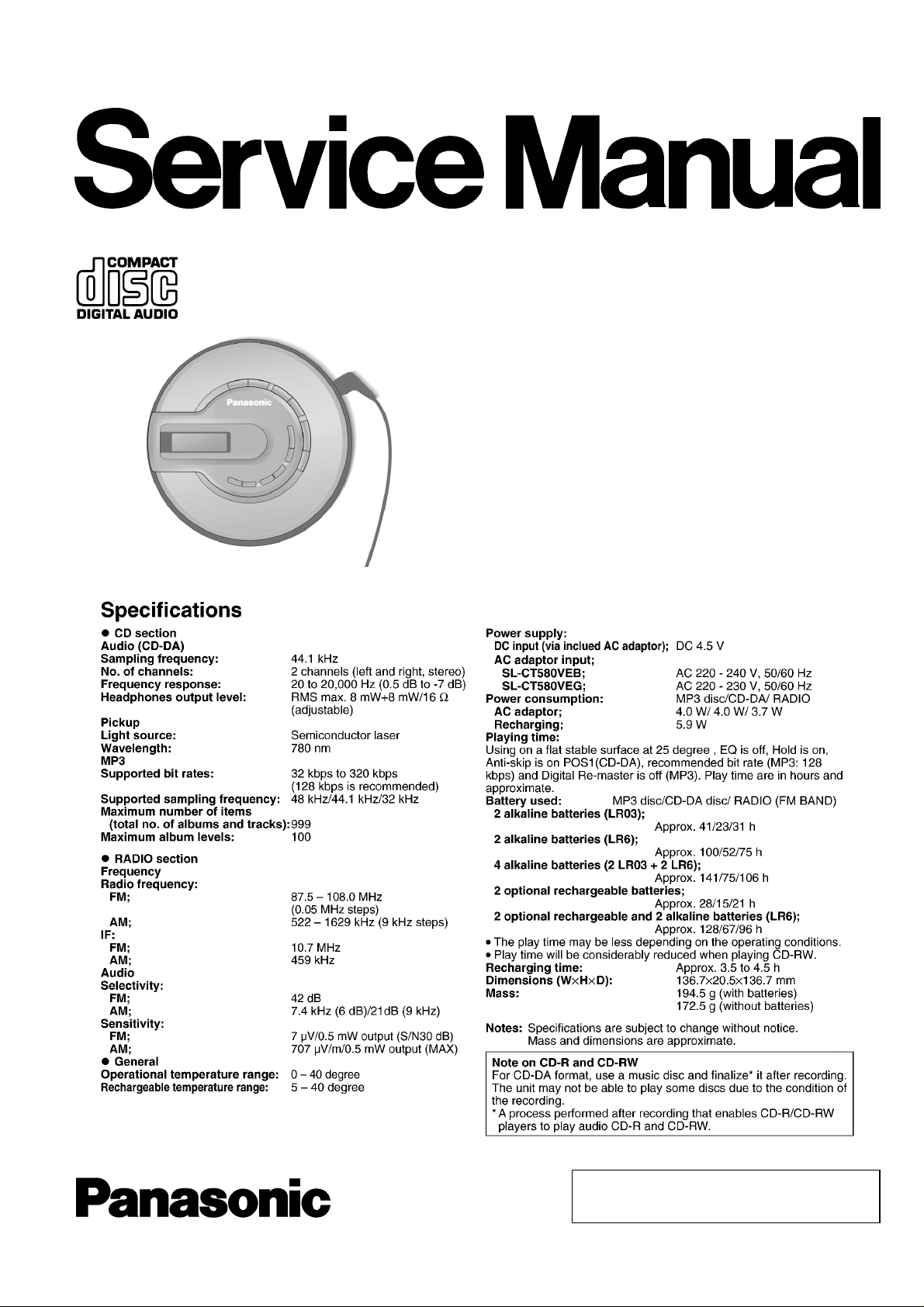
Portable CD Player
SL-CT580VEB
SL-CT580VEG
Colour
(S)..........Silver Type
AD0502012C2
© 2005 Matsushita Electric Industrial Co., Ltd. All
rights reserved. Unauthorized copying and
distribution is a violation of law.
SL-CT580VEB / SL-CT580VEG
CONTENTS
Page Page
1 Accessories 2
2 Location of Controls
3 Precaution of Laser Diode
4 Handling Precautions for Traverse Deck
4.1. Handling of traverse deck (optical pick-up)
4.2. Caution when replacing traverse deck
4.3. Grounding for electrostatic breakdown prevention
5 Operation Checks and Component Replacement Procedures
5.1. Checking for the P.C.B.
5.2. Replacement for the CD lid unit
5.3. Replacement for the LCD, VOL/OPR etc. button,
MEMORY/EQ etc. button, Lid ornament and multi button
SW unit
5.4. Replacement for the retainer plate, open spring 1 and
open spring 2
5.5. Replacement for the traverse motor
5.6. Replacement for the optical pick-up
5.7. Replacement for the rest switch
6 Display of Self-Diagnostic Function
7 Checking the Operation Problems on the Traverse Deck
(Optical Pick-up)
7.1. Check the operations described below on the traverse
deck after replacing
8 Automatic Adjustment Results Display Function (Self-Check
3
4
5
5
5
5
6
6
8
9
9
10
10
12
12
13
13
Function)
8.1. How to display automatic adjustment results
8.2. Display of automatic adjustment results (Self-Check
Function)
9 Type Illustration of ICs, Transistors and Diodes
10 Schematic Diagram Notes
10.1. Cautions in Repair exchange of the Diode (D1101, D1102)
11 Schematic Diagram
12 Printed Circuit Board and Wiring Connectio n Diagram
13 Block Diagram
14 Terminal Function of ICs
14.1. IC301(C2BBGF000593): System Control
14.2. IC501(MN6627962JB): Servo Amp, Servo Processor,
Digital Signal Processor, Digital Filter & D/A Converter
14.3. IC1301(C2FBEB000007): System Control/LCD Drive
15 Measurem ents and Adjustments
15.1. Tuner section
16 Replacement Parts List
17 Cabinet Parts Location
18 Traverse Unit Parts Location
19 Packaging
14
14
14
15
16
16
17
23
25
27
27
27
28
30
30
31
35
36
37
1 Accessories
· AC adaptor for SL-CT580VEB
(N0JCCE000004)..........................................1 pc.
· AC adaptor for SL-CT580VEG
(RFEA419E-M)................................................1 pc.
· Stereo earphones
(L0BAB0000182)...........................................1 pc.
· External battery case
(RFA2666-H)..................................................1 pc.
2

2 Location of Controls
SL-CT580VEB / SL-CT580VEG
3
SL-CT580VEB / SL-CT580VEG
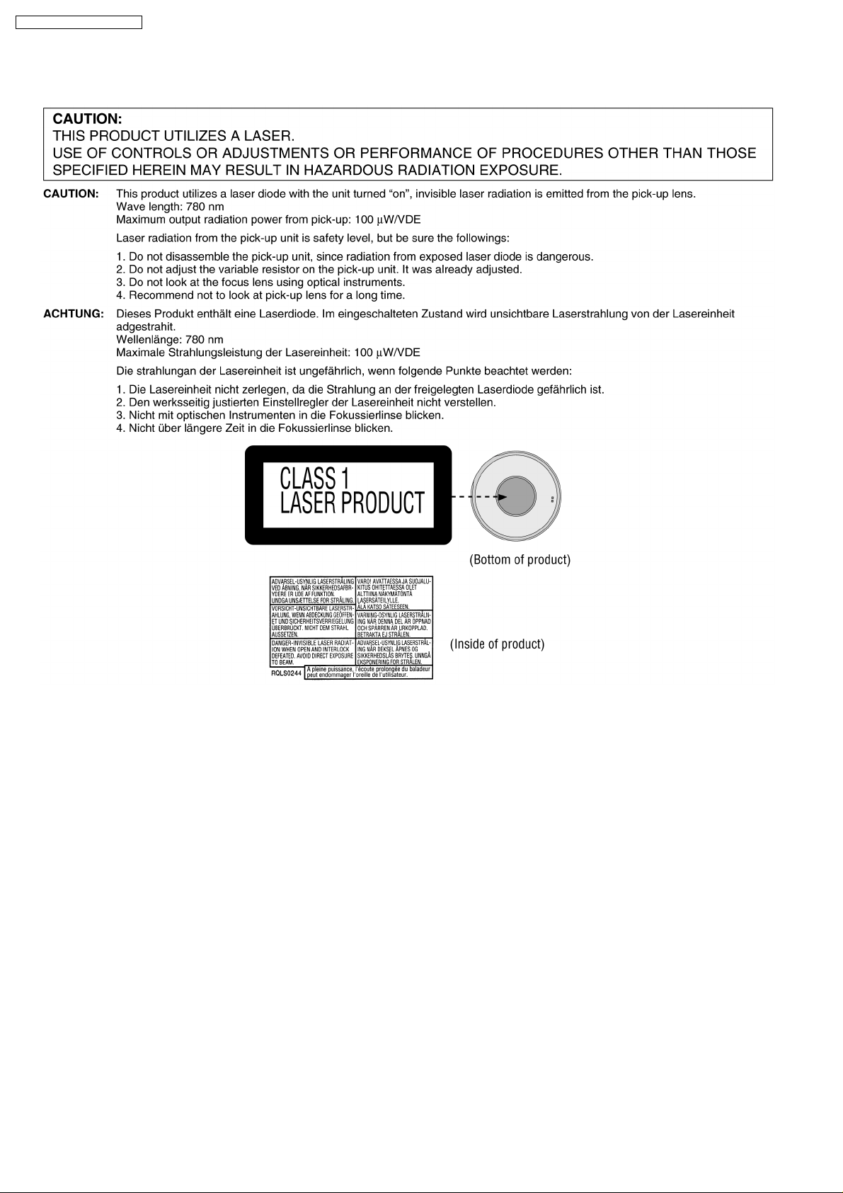
3 Precaution of Laser Diode
4

4 Handling Precautions for Traverse Deck
SL-CT580VEB / SL-CT580VEG
The laser diode in the traverse deck (optical pick-up) may break
down due to potential difference caused by static electricity of
clothes or human body.
So, be careful of electrostatic breakdown during repair of the
traverse deck (optical pick-up).
4.1. Handling of traverse deck
(optical pick-up)
1. Do not subject the optical pick-up to static electricity as it is
extremely sensitive to electrical shock.
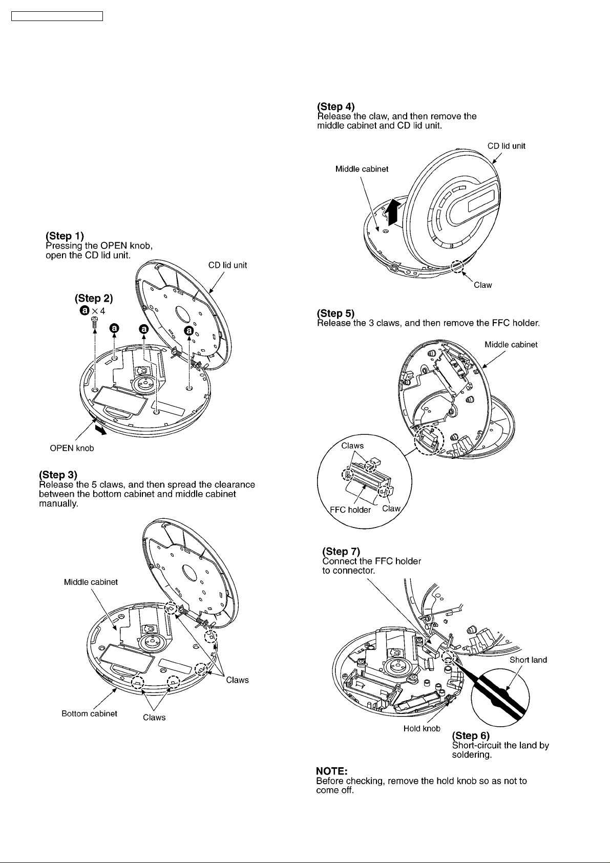
2. To protect the laser diode against electrostatic breakdown,
be sure that the short land of the flexible board (FFC board)
should be short-circuit by solder before pulling out the FFC.
Then inserting a short pin or similar object into the tip of the
flexible board.
(Refer to Fig. 4-1.)
3. Take care not toapply excessive stress to the flexible board
(FFC board).
4. Do not turn the variable resistor (laser power adjustment). It
has already been adjusted. (Refer to Fig. 4-1.)
4.2. Caution when replacing
traverse deck
The new traverse deck short-circuits by the short pin, the foil
(B) and short lands to protect the laser diode against
electrostatic breakdown. Be sure to replace to new one
following procedures.
1. Remove the short pin from the FFC, and then connect it to
the connector.
2. Cut the foil (B). (Refer to Fig. 4-1.) (Take care not to make
contact with cutting point each other.)
3. Unsolder the short lands. (Refer to Fig. 4-1.)
4.3. Grounding for electrostatic
breakdown prevention
4.3.1. Human body grounding
Use the anti-static wrist strap to discharge the static electricity
from your body. (Refer to Fig. 4-2.)
Fig. 4-1.
Fig. 4-2.
4.3.2. Work table grounding
Put a conductive material (sheet) or steel sheet on the area
where the traverse deck (optical pick-up) is placed, and ground
the sheet. (Refer to Fig. 4-3.)
Fig. 4-3.
Caution:
The static electricity of your clothes will not be grounded
through the wrist strap.
So take care not to let your clothes touch the traverse deck
(optical pick-up).
5
SL-CT580VEB / SL-CT580VEG
5 Operation Checks and Component Replacement
Procedures
· This section describes procedures for checking the
operation of the major printed circuit boards and
replacing the main components.
· For reassembly after operation checks or replacement,
reverse the respective procedures. Special reassembly
procedures are described only when required.
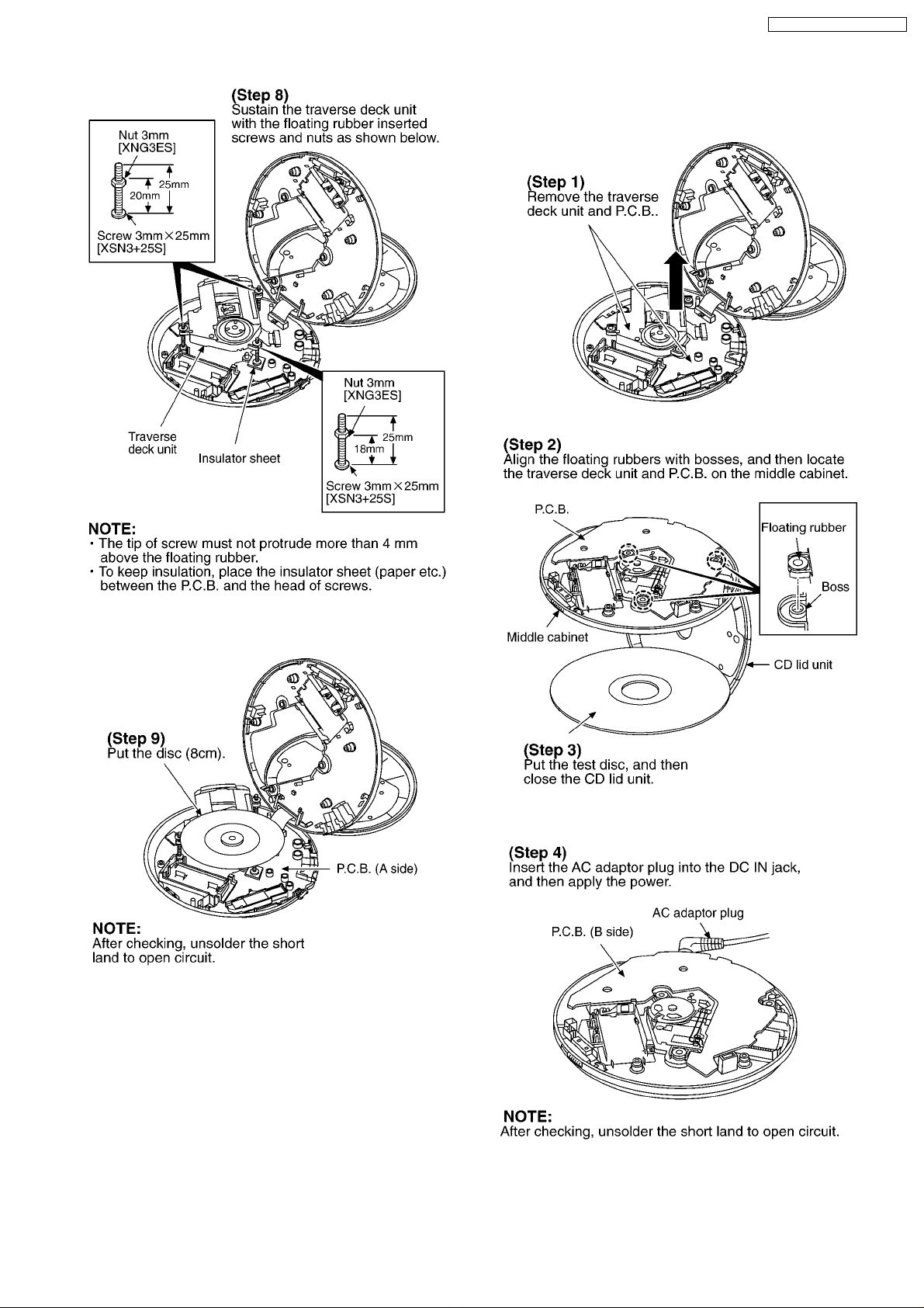
5.1. Checking for the P.C.B.
5.1.1. Checking for the P.C.B. (A side)
6
SL-CT580VEB / SL-CT580VEG
5.1.2. Checking for the P.C.B. (B side)
· Follow the (Step 1) - (Step 7) of item 5.1.1.
· Check the P.C.B. (A side) as shown below.
· Check the P.C.B. (B side) as shown below.
7

SL-CT580VEB / SL-CT580VEG
5.2. Replacement for the CD lid
unit
· Follow the (Step 1) - (Step 5) of item 5.1.1.
8
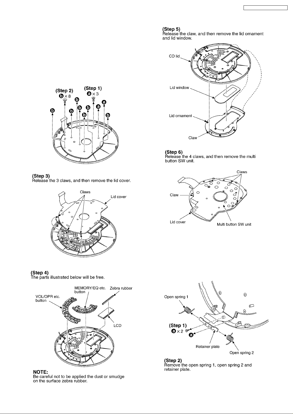
5.3. Replacement for the LCD,
VOL/OPR etc. button,
MEMORY/EQ etc. button, Lid
ornament and multi button SW
unit
· Follow the (Step 1) - (Step 5) of item 5.1.1.
· Follow the (Step 1) - (Step 4) of item 5.2.
SL-CT580VEB / SL-CT580VEG
5.4. Replacement for the retainer
plate, open spring 1 and open
spring 2
· Follow the (Step 1) - (Step 5) of item 5.1.1.
· Follow the (Step 1) - (Step 4) of item 5.2.
9

SL-CT580VEB / SL-CT580VEG
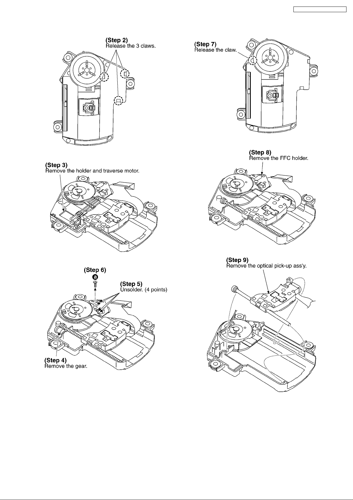
5.5. Replacement for the traverse
motor
· Follow the (Step 1) - (Step 4) of item 5.1.1.
5.6. Replacement for the optical
pick-up
· Follow the (Step 1) - (Step 4) of item 5.1.1.
· Follow the (Step 1) - (Step 3) of item 5.5.
10
SL-CT580VEB / SL-CT580VEG
11

SL-CT580VEB / SL-CT580VEG
5.7. Replacement for the rest
switch
· Follow the (Step 1) - (Step 4) of item 5.1.1.
· Follow the (Step 1), (Step 2) of item 5.5.
6 Display of Self-Diagnostic
Function
This unit (SL-CT580V) has self-diagnostic function. It may
display below-mentioned on the LCD of this unit.
· The substance of self-diagnostic display.
LCD display
(Press PLAY and STOP button. After 15 seconds, it is
displayed for 2 seconds.)
In case of this display, it may be causing for abnormally
movements of traverse deck, touching failure of REST detect
switch and coming off or cutting off the flexible P.C.B.. It is
necessary for confirmation or repair and replacement each
parts.
12
 Loading...