

Panasonic SLCT-350-EE, SLCT-350-EB, SLCT-350-EG, SLCT-350-GN Service manual
o
/
A
Portable CD Player
SL-CT350EB
SL-CT350EE
SL-CT350EG
SL-CT350GN
Colours
(S)..................Silver Type
ORDER No.AD050200 5C8
Specification
●●●●Audi
Sampling frequency: 44.1 kHz
No. ofchannels: 2 (left and right, stereo)
Headphone outputlevel: M3, RMS max.6mW+6mW
16Ω
(adjustable)
Frequencyresponse: 20 Hz to 20,000 Hz
(+0.5dB to -7dB)
●●●●Pickup
Lightsource: Semiconductor laser
Wavelength: 780 nm
●●●●General
Power supply:
DC input; DC 4.5V
AC adaptor input; EB:AC220V-240V 50/60Hz
EG/EE:AC220V-230V 50/60Hz
GN:AC230V-240V 50Hz
Using AC adaptor; 0.8W
Recharging; 3.0W
Playtime:
Using on a flat stable surface at 25°C°, EQ is off, Hold is on,Antiskip is on POS 1.
Play times are in hours and approximate.
Recharging time:
· The playtime maybe less depending on the operating conditions.
· Play time will be considerably reduced when playing CD-RW.
Dimensions (WxHxD): 136.7x21.5x136.7mm
Mass: 180g (with batteries)
bout 3.5 to 4.5 hours
157g (without batteries)
© 2005 Matsushita Electric Industrial Co., Ltd. All
rights reserved. Unauthorized copying and
distribution is a violation of law.

SL-CT350EB / SL-CT350EE / SL-CT350EG / SL-CT350GN
Operational temperature range: 0°C-40°C
Rechargeable temperature range: 5°C-40°C
Note:
Specifications are subject to change without notice.
Mss and dimensions are approximate.
Note on CD-R and CD-RW:
This unit can playCD-DA format audio CD-R and CD-RW that have
been finalized* upon completion of recording. it may not be able to
play some CD-R or CD-RW due to the condition of the recording.
*Finalizingisaprocess that enables CD-R/CD-RW players to play
audio CD-R and CD-RW.
CONTENTS
Page Page
1 Precaution of Laser Diode 2
2 Accessories
3 Handling Precautions for Traverse Deck
3.1. Handling the traverse deck (optical pickup)
3.2. Caution when replacing traverse deck
3.3. Grounding for electrostatic breakdown prevention
4 Operation Checks and Component Replacement Procedures
4.1. Checking for the P.C.B. ass 馳
4.2. Replacement for the CD lid unit, retainer plate and open
spring
4.3. Replacement for the LCD, button A, button B and multi
button SW unit
4.4. Replacement for the traverse motor
4.5. Replacement for the optical pick-up
4.6. Replacement for the rest switch
5 Checking the Operation Problems on the Traverse Deck
(Optical Pickup)
6 Automatic Adjustment Results Display Function (Self-check
Function)
6.1. How to display automatic adjustment results
10
10
12
13
14
14
3
4
4
4
4
6
6
8
9
6.2. Display of automatic adjustment results (self-check
function)
7 Display of Self-Diagnostic Function
8 Type Illustration of ICエs, Transistors and Diodes
9 Schematic Diagram Notes
10 Schematic Diagram
11 Printed Circuit Board and Wiring Connection Diagram
12 Block Diagram
13 Terminal Function of ICs
13.1. IC101(AN22003A-NF): Servo Amplifier
13.2. IC301(C2BBFD000574): System Control / LCD Drive
13.3. IC501(MN6627881SE): Servo Processor, Digital Signal
Processor, Digital Filter & D/A Converter
14 Replacement Parts List
15 Cabinet Parts Location
16 Traverse Parts Location
17 Packaging
17.1. SL-CT350EB
17.2. SL-CT350EE/EG/GN
14
15
15
16
17
21
23
25
25
25
26
27
29
30
31
31
32
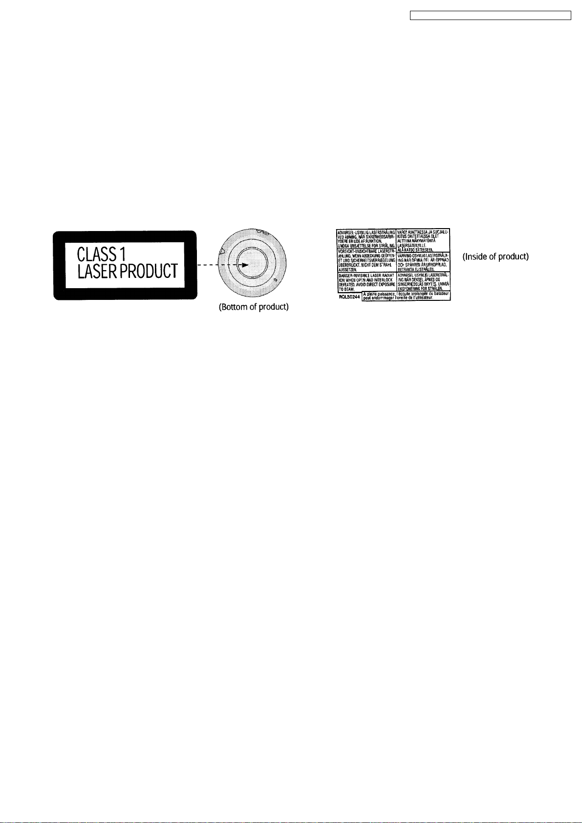
1 Precaution of Laser Diode
CAUTION:
This unit utilizes a class 1 laser. Invisible laser radiation is emitted from the pickup lens when the unit is turned on:
1. Do not look directly into the pickup lens.
2. Do not use optical instruments to look at the pickup lens.
3. Do not adjust the preset variable resistor on the optical pickup.
4. Do not disassemble the optical pickup unit.
5. If the optical pickup is replaced, use the manufactures specified replacement pickup only.
6. Use of control or adjustments or performance of procedures other than those specified herin may result in hazardous
radiation exposure.
CAUTION:
This product utilizes a liser diode with the unit turned “on”, invisible laser radiation is emitted from the pickup lens.
Wave length: 780nm
Maximum output wadiation power from pickup: 100 µW/VDE
Laserradiationfromthepickuplens is safety level, but be sure the followings:
1. Do not disassemble the optical pickup unit, since radiation from exposed laser diode is dangerous.
2
SL-CT350EB / SL-CT350EE / SL-CT350EG / SL-CT350GN
2. Do not adjust the variable resistor on the pickup unit. It was already adjusted.
3. Do not look at the focus lens using optical instruments.
4. Recommend not to look at pickup lens for a long time.
ACHTUNG:
Dieses Produkt enthalt eine Laserdiode. Im eingeschalteten Zustand Wird unsichtbare Leserstrahlung von der Lasereinheit
abgestrahlt.
Wellenlage: 780nm
Maximale Strahlungsleistung der Lasereinheit: 100 µW/VDE
Die StrahlungasderLasereinheitistungefahrlich, wenn folgende Punkte beachtet werden:
1. Die Lasereinheit nicht zeriegen, de die Strahlung an der freigelegten Laserdiode gefahrlich ist.
2. Denwerkseitig Justierten Einstellregler der Lasereinhit nicht verstellen.
3. Nicht mit optischen Instrumenten in die Fokussierlines blicken.
4. Nicht uber langere Zeit in die Fokussierlines blicken.
2 Accessories
· Stereo earphones..................................................1 pc.
(L0BAB0000185)
· AC adaptor...............................................................1 pc.
(EB: RFEA435B-S)
(EE, EG: RFEA431E-S)
(GN: RFEA436A-S)
EE/GN only
· External battery case..............................................1 pc.
(RFA2666-H)
3

SL-CT350EB / SL-CT350EE / SL-CT350EG / SL-CT350GN
3 Handling Precautions for Traverse Deck
The laser diode in the traverse deck (optical pickup) may break
down due to potential difference caused by static electricity of
clothes or human body.
So, be careful of electrostatic breakdown during repair of the
traverse deck (optical pickup).
3.1. Handling the traverse deck (optical pickup)
1. The traverse deck (optical pickup) is an extremely highprecision construction and must not be subjected to impact,
excessive vibration, or other types of rough handling.
2. To protect the laser diode against electrostatic breakdown,
be sure that the short land A and B of the flexible board
(FFC board) should be short-circuit by solder before pulling
out the FFC. Then inserting a short pin or similar object
intothetipoftheflexible board.
(Refer to Fig. 1 )
3. Handle the flexible circuit boards with care; excessive force
could cause them to be broken.
4. Do not turn the pre-set variable resistor (for adjustment of
the laser power); it has been adjusted at the factory.
(as shown in Fig. 1 )
3.2. Caution when replacing traverse deck
The new traverse deck short-circuits by the short pin, the foil
(C) and short lands to protect the laser diode against
electrostatic breakdown. Be sure to replace to new one
following procedures.
1. Remove the short pin from the FFC, and then connect it to
the connector.
2. Cut the foil (C). (Refer to Fig. 1 ) (Take care not to make
contact with cutting point each other.)
3. Unsolder the short lands. (Refer to Fig. 1 )
3.3. Grounding for electrostatic breakdown prevention
1. Human body grounding
Use the anti-static wrist strap to discharge the static
electricity from your body. (as shown in Fig. 2 )
2. Work table grounding
Put a conductive material (sheet) or steel sheet on the area
where the optical pickup is placed, and fround the sheet.
(as shown in Fig. 3 )
Caution
The static electricity of your clothes will not be grounded
through the wrist strap.
So, take care not to let your clothes touch the traverse deck
(optical pickup).
Fig. 1
Fig. 2
4

Fig. 3
SL-CT350EB / SL-CT350EE / SL-CT350EG / SL-CT350GN
5
SL-CT350EB / SL-CT350EE / SL-CT350EG / SL-CT350GN
4 Operation Checks and Component Replacement
Procedures
· This section describes procedures for checking the
operation of the major printed circuit boards and
replacing the main components.
· For reassembly after operation checks or replacement,
reverse the respective procedures. Special reassembly
procedures are described only when required.
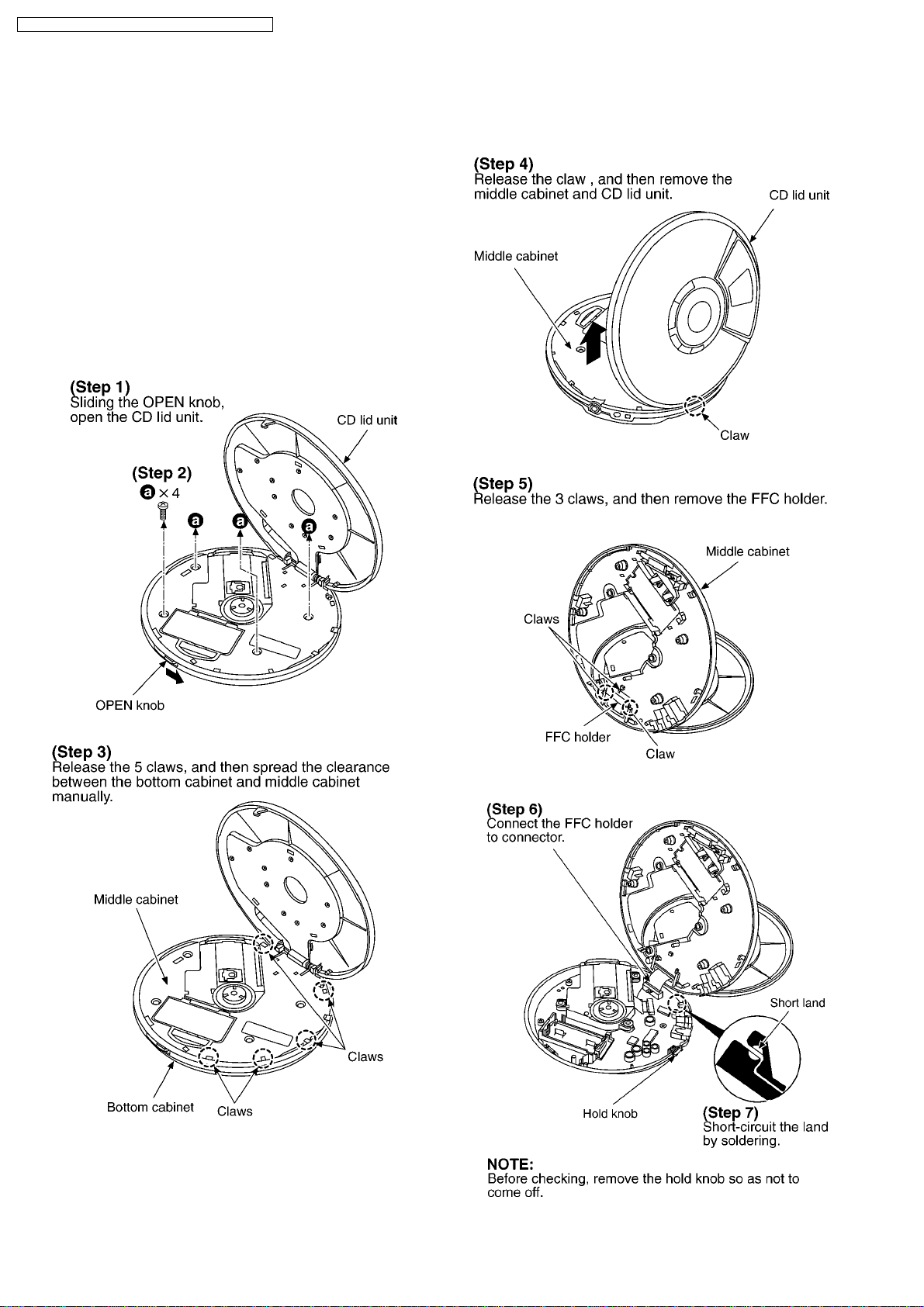
4.1. Checking for the P.C.B. ass’y
4.1.1. Checking for the P.C.B. ass’y
(A side)
6
SL-CT350EB / SL-CT350EE / SL-CT350EG / SL-CT350GN
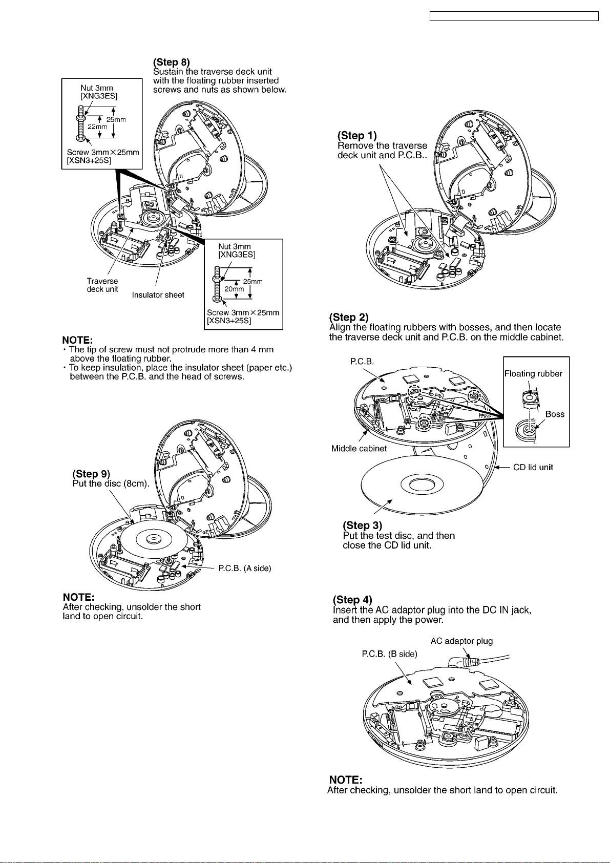
4.1.2. Checking for the P.C.B. ass’y
(B side)
· Follow the (Step1)-(Step7) of item 4.1.1.
· Check the P.C.B. ass’y (A side) as shown below.
· Check the P.C.B. ass’y (B side) as shown below.
7

SL-CT350EB / SL-CT350EE / SL-CT350EG / SL-CT350GN
4.2. Replacement for the CD lid
unit, retainer plate and open
spring
· Follow the (Step1)-(Step5) of item 4.1.1.
8
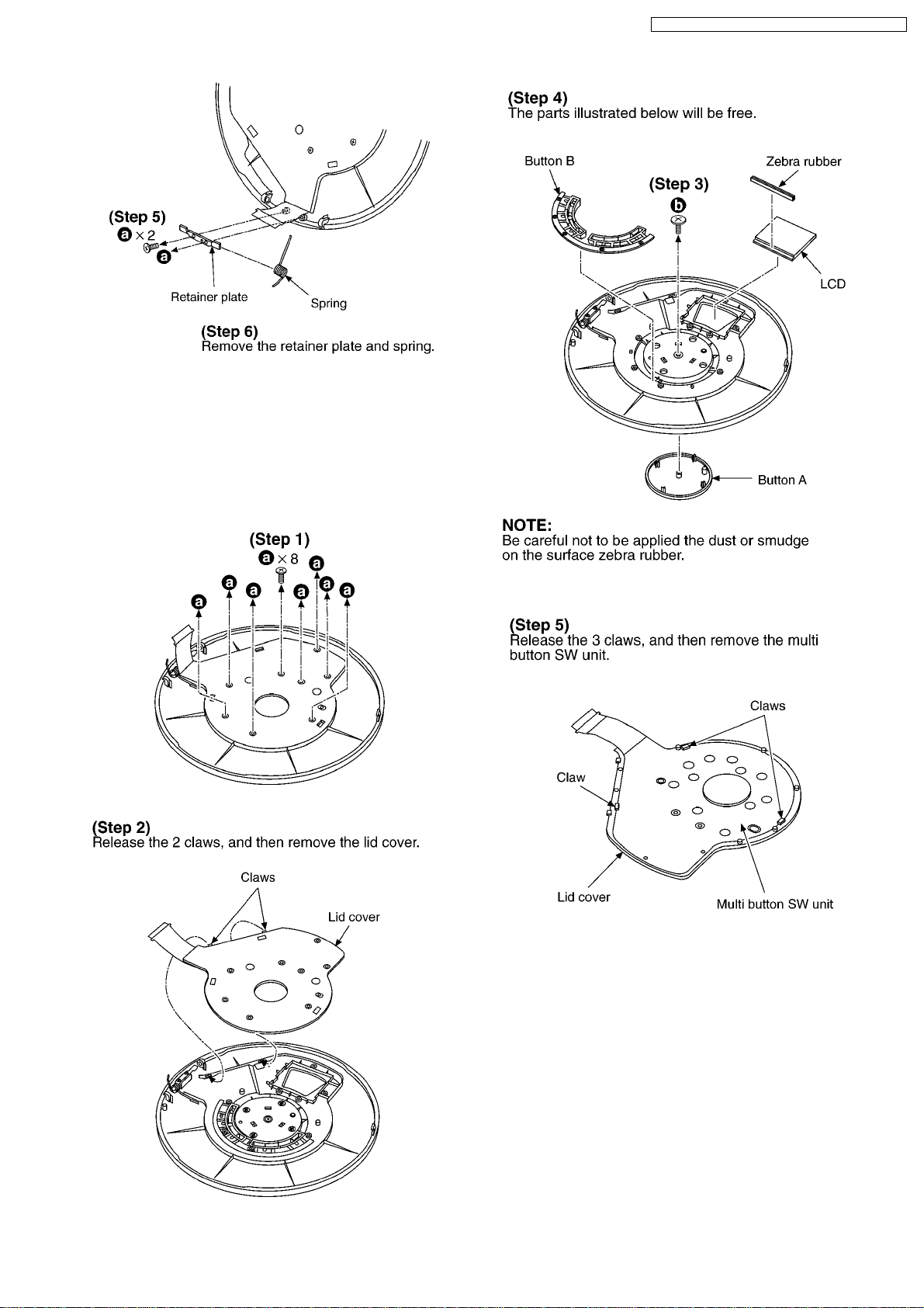
4.3. Replacement for the LCD,
button A, button B and multi
button SW unit
SL-CT350EB / SL-CT350EE / SL-CT350EG / SL-CT350GN
· Follow the (Step1)-(Step5) of item 4.1.1.
· Follow the (Step1)-(Step4) of item 4.2.
9
SL-CT350EB / SL-CT350EE / SL-CT350EG / SL-CT350GN
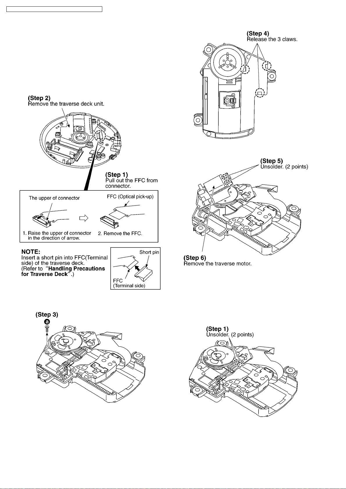
4.4. Replacement for the traverse
motor
· Follow the (Step1)-(Step4) of item 4.1.1.
NOTE:
Be sure to confirm the item 3 “Handling Precautions for
Traverse Deck” before removing the traverse deck unit.
4.5. Replacement for the optical
pick-up
· Follow the (Step1)-(Step4) of item 4.1.1.
· Follow the (Step1)-(Step3) of item 4.4.
10
 Loading...