

Panasonic SL70 User Manual [en, es, fr]

Operating
Instructions
Multi-Scan Color Monitor
Panasonic
These Operating Instructions are for units for sale and use in
the United States of America and Canada only.
Read these instructions completely before operating this display monitor.

IMPORTANT NOTICE CONCERNING POWER CORD SELECTION
The power cord for this unit has been packed separately and has been selected according to the country of destination and
must be used to prevent electric shock. Use the following guidelines If it Is necessary to replace the original cord set.
The female receptacle of the cord set must meet CEE-22 requirements and will look like Figure 1 :
WICHTIGE INFORMATION BEZÜGLICH DES ZU BENUTZENDEN NETZKABELS
Das Netzkabel für diese Geräteeinheit wird separat verpackt geliefert und entspricht jeweils den landesspezifischen
Anforderungen. Aus Gründen der Unfallverhütung ist die Benutzung dieses Netzkabels zwingend. Beachten Sie bitte folgende
Hinweise, wenn ein Austausch des Originalkabels erforderlich ist. Der geräteseitige Stecker des Netzkabels muß den CEE-22
Anforderungen sowie dem In Abb. 1 gezeigten Beispiel entsprechen.
AVISO IMPORTANTE RESPECTO A LA SELECCION DEL CABLE DE SUMINISTRO ELECTRICO
El cable de suministro eléctrico de esta unidad ha sido empacado en forma separada, ha sido seleccionado de acuerdo con el
país de destino y debe ser usado para prevenir sobrecargas eléctricas. Use las guías descritas a continuación, si es necesario
reemplazar el cable original. El receptáculo hembra del cable debe cumplir los requerimientos CEE-22 y se verá como aparece
en la Figura 1.
NOTICE IMPORTANTE CONCERNANT LE CHOIX DU CORDON D’ALIMENTATION
Le cordon d'alimentation conçu pour cette unité a été conditionné dans un emballage distinct et il a été choisi en fonction du
pays de destination. Son utilisation vise à vous prévenir de toute décharge éiectrique. Si vous devez remplacer le cordon initial,
veuillez suivre tes informations ci-dessous mentionnées. Le receptacle femelle du cordon doit satisfaire aux normes CEE-22 et
comporter les caractéristiques présentées au schéma 1.
For the United States and Canada
In the United States and Canada the male plug Is a NEMA 5-15 style (Figure 2) and is UL listed and CSA labelled. For units
which are mounted on a desk or table, type SVT or SJT cord sets may be used. For units which sit on the floor, only SJT type
cord sets may be used. The cord set must be selected according to the current rating for your unit. Please consult Table A for
the selection criteria for power cords used in the United States and Canada. (The cord set is marked with its Cord Type.)
U.S.A. und Kanada:
ln den U.S.A. und Kanada verfügt das Kabel netzseitig über einen Stecker des Typs NEMA 5-15 (Abb. 2), der den ULSicherheitsbestimmungen entspricht und die Markierung CSA trägt. Für Geräte, die auf einer Arbeitsfläche wie Tisch oder
Schreibtisch installiert sind, können Netzkabel des Typs SVT oder SJT benutzt werden. Die Auswahl des Netzkabels muß
gemäß dem für das Gerät zutreffenden Stromaufnahme-Nennwert erfolgen. Tabelle A enthält eine Aufstellung der Kriterien, die
bei der Wahl des Netzkabels in den U.S.A. und Kanada zu berücksichtigen sind. (Der Kabelsatz Ist mit dem Kapbeltyp
markiert.)
Para los Estados Unidos y Canadá
En los Estados Unidos y en Canadá el conector macho es estilo NEMA 5-15 (Figura 2), está listado UL y etiquetado CSA. Para
las unidades que están montadas sobre un escritorio o sobre una mesa, debe usarse el cable tipo SVT o SJT. Para unidades
que están sobre el piso, sólo se debe usar el cable tipo SJT. El cable debe ser seleccionado de acuerdo al tipo de voltaje de su
unidad. Consulte en la Tabla A los criterios de selección de los cables de suministro eléctrico usados en los Estados Unidos y
en Canadá.(EI juego de cables está marcados con su tipo de cables.)
Etas-Unis et Canada
Aux Etats-Unis ainsi qu’au Canada, la prise mâle est de type NEMA 5-15 (schéma 2): elle est mentionnée dans la liste UL et
porte la mention CSA. En ce qui concerne les unités qui sont placées sur une table ou sur un bureau, il est possible d'utiliser
des cordons de type SVT ou SJT. Quant aux unités qui sont placées à môme le sol, seuls des cordons de type SJT peuvent
être utilisés. Le choix du cordon doit s’effectuer en fonction de l'ampérage de votre unité. Veuillez consulter le tableau A suivant
les critères de selection des cordons d'alimentation utilisés aux Etats-Unis et au Canada.(Le jeu de cordon est marqué du type
du cordon.)

For European Countries:
In Europe you must use a cord set which Is appropriate for the receptacles in your country. The cord set is HARCertified, and the mark 4 HAR > will appear on the outer sheath, or on the insulation of one of the inner conductors.
If you have any questions concerning the proper power cord to use, please consult with the dealer from whom you purchased
your unit.
Europa:
In den europäischen Ländern ist das für den Anschluß an das jeweilige Netz erforderliche Kabel zu verwenden. Das
Kabel muß den HAR-Antorderungen entsprechen und auf der Außen Isolierung oder auf der Isolierung einer der
Kabeladern die Markierung
Sollten Sie hinsichtlich der Anwendung des richtigen Kabels Irgendwelche Fragen haben, so konsultieren Sie bitte Ihren
Händler, von dem Sie Ihr Gerät erworben haben.
4 HAR >■ aufweisen.
Para los países europeos;
En Europa debe usar el cable apropiado al receptáculo usado en su país. El cable es HAR certificado y la marca
4 HAR ^ aparecerá en el forro externo o en la cubierta aislante de uno de los conductores Internos.
Si tiene dudas acerca del cable apropiado que se debe usar, consulte la tienda donde adquirió su unidad.
Pays européens:
En Europe, vous devez utiiiser des cordon appropriés aux prises de votre pays. Les cordons doivent être de marque
4 HAR ^ et celle-ci doit apparaître sur ta gaine plastique externe ou sur la partie isolante d’un des conducteurs
internes.
Si vous avez des questions concernant le bon cordon à utiliser, vous êtes priés de consulter le concessionnaire chez qui vous
avez acheté votre appareil.
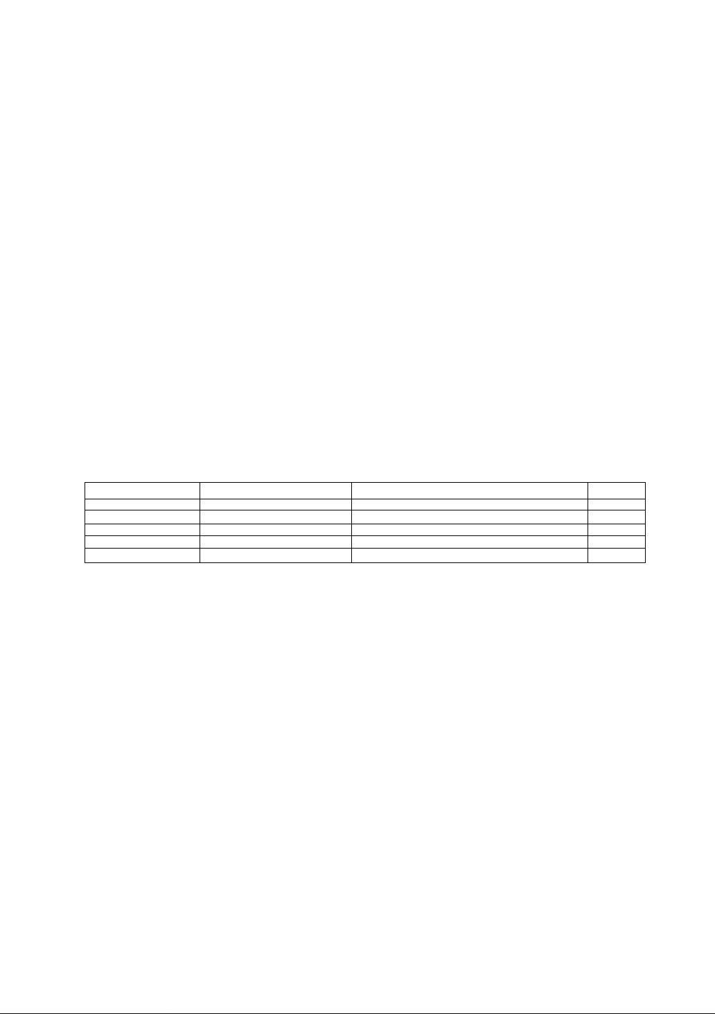
Table A Tabelle A Tabla A Tableau A
Cord Type Size of Conductors In Cord Maximum Current Rating of Unit
Kabeltyp Größe der Kabeladern Max. Stromaufnahme des Geräts
Tipo de cable Tamaño de los conductores del
Máximo voltaje de acuerdo a la
cable unidad
Type de cordon
Taille des conducteurs dans le
Ampérage maximum de l’unité
cordon
SJT
18AWG lOAmps
16AWG 12Amps
UAWG 12Amps
SVT 18AWG 10Amps
17AWG 12Amps
Figure 1 Abb. 1 Figura 1 Schéma 1
Figure 2 Abb. 2 Figura 2 Schéma 2

Federal Communications Commission Requirements
This equipment has been tested and found to comply with the iimits for Ciass B digital devices, pursuant
to Part 15 of the FCC Ruies. These limits are designed to provide reasonable protection against harmful
interference in a residential installation. This equipment generates, uses, and can radiate radio frequency
energy and, if not installed and used in accordance with the instructions, may cause harmful interference
to radio communications. However, there is no guarantee that interference will not occur in a particular
installation. If this equipment does cause harmful interference to radio or television reception, which can
be determined by turning the equipment off and on, the user is encouraged to try to correct the interfer
ence by one or more of the following measures:
- Reorient or relocate the receiving antenna.
- Increase the separation between the equipment and receiver.
- Connect the equipment into an outlet on a circuit different from that to which the receiver is
connected.
- Consult the dealer or an experienced radlo/TV technician for help.
FCC Warning:
To assure continued FCC compliance, the user must use the provided grounded power supply
cord and shielded interface cable with bonded ferrite cores. Also, any unauthorized changes or
modifications to this monitor would void the user’s authority to operate this device.
CE Conformity
This device complies with the requirements of the EEC directive 89/336/EEC as
amended by 92/31/EEC and 93/68/EEC Art. 5 with regard to “Electromagnetic
C€
Required item
EM l #1
ESD #2
RADIATED RF #1
TRANSIENT F/B
LINE HARMONICS #1
#1 : Satisfies standards with no problems in performance and reliability.
#2 : Effects may appear temporarily on the screen but there will be no problem in reliability.
#3 : There is fear of the product breaking down.
#4 : If a signal cable other than that specified is used, it may be the cause of electromagnetic
Handle correctly in accordance with the instruction manual.
EMI: Electromagnetic Interference ESD : Electrostatic Discharge
RF : Radio Frequency F/B : Fast Burst
compatibility, and 73/23/EEC as amended by 93/68/EEC Art. 13 with regard to “Safety”.
Relative to Standard ValueRelative to those Exceeding Standard ValueRemarks
#3
___
___________m___________
wave interruption of peripheral devices.
To assure continued CE compliance the user must use the provided 1.5 m shielded
video signal cable with bonded ferrite cores at both ends of the cable.
---------
#3
#3
-----
----------------------
#4
/ \
As an Energy Star* partner, Panasonic Computer Peripheral Company has determined that this product
meets the Energy Star* guidelines for energy efficiency.
— IV —

AA
To avoid the risk of severe electrical shock including death, do not remove
covers (or back) of monitor. No user serviceable parts are inside.
Refer servicing to qualified service personnel.
AA
To prevent risk of electric shock and possible fire:
Never place any object on the monitor, AC line cord, or cause the cords to make
sharp bends, or otherwise do anything that can affect the integrity of the cords.
Aiways remove the line cord from the socket by holding the piug, not the cord.
Do not place anything containing any iiquid (even a wet or damp cloth) on the
monitor as the introduction of fluids can create an electrical hazard. Do not
expose the monitor to rain or moisture.
Do not piace the monitor with less than the recommended clearance (see
Precautions, 1 Installation Page 2). Do not block the ventilation openings with
anything. Do not insert any objects Into the ventilation openings.
Customeir’s Recordl
The serial number of this product is printed on its back cover label.
Note this serial number in the space provided and retain this booklet as a permanent record of
your purchase to aid in identification of the unit in the event of theft or loss.
Model number : SL70
Serial number :
Table of Contents
Important Notice Concerning Power Cord Selection
Federal Communications Commission Requirements
CE Conformity.................................................................................iv
Danger.............................................................................................1
Warnings
Customer’s Record..........................................................................1
Table of Contents............................................................................1
Precautions 1)lnstallation.................................................................2
Precautions 2)Usage
Precautions 3)Product Care
Features ..........................................................................................3
Specifications...................................................................................4
Installation........................................................................................5
Pin Assignment................................................................................6
External View...................................................................................7
Pedestal removal.............................................................................8
On-Screen Adjustment.....................................................................9
Operation
Power Management System..........................................................14
Memories ......................................................................................14
Timing Specifications.....................................................................15
Trouble Shooting ...........................................................................18
Technical Support .........................................................................19
Index ............................................................................................. 19
Notice for Germany........................................................................20
Notice for Japan.............................................................................20
ALL PRODUCT/BRAND NAMES ARE TRADEMARKS OR REGISTERED TRADEMARKS OF THE RESPECTIVE HOLDERS.
© 1997 MATSUSHITA ELECTRIC INDUSTRIAL Co.. Ltd.
.........................................................................................
.......................................................................
............................................................
......................................................................................
-1 -
........................
....................
i
iv
1
2
2
10

1) Installation
® Install the monitor in a well ventilated place. Avoid exposing to direct sunlight, a
heater, or any other heat source. Heat will adversely affect the cabinets and the
parts inside.
»Position the display unit so that the holes in the cabinet will not be blocked during use.
• Keep the display unit away from the kitchen, bathroom, washing machine, or other
sources of exposed to water, steam or moisture.
* In order to use the display unit safely, use only the supplied AC line cord. The AC line
cord must be used with a properly grounded and polarized power supply socket. The
AC line cord supplied is for the USA (UL) and Canada (CSA) for use with the display
unit. For use in other countries, make sure the AC line cord meets the safety
standards of the country.
• Place the AC line cord where it will not be subject to stress.
* Use only Panasonic provided accessories or the exact equivalent.
2) Usage
• Pulling on the AC line cord or VGA Signal Cable can damage the display unit
(monitor) and can cause the unit to fall and possibly cause personal injury.
• Receiving trouble.
If there is a television set or other display unit nearby, keep your display unit as far
away from it as possible. Mutual interference can cause image distortion or noise.
• Long exposure to rubber or vinyl products can stains the cabinet.
• Keep the monitor from physical shock when moving. Be careful of the Cathode Ray
Tube (CRT).
* Do not place anything on the monitor.
«Also take good care of the power code:
Do not place any objects on the power cable. Do not attempt to extend, shorten or tie
it into a knot.
3) Product Care
* Prior to cleaning your display unit, disconnect the AC line cord and the VGA Signal
Cable from the display unit.
* Use a clean, soft, dry cloth to clean the outside of the monitor or the CRT surface.
If the monitor or CRT surface is very dirty, wet a clean, soft cloth with neutral
detergent (such as dishwashing detergent) and water, squeeze it tight until almost dry,
wipe the monitor or CRT surface with it, and finish by wiping with a clean dry cloth.
Do not use any solvents.
»Do not rub or strike the monitor with anything hard or harsh as this may scratch, mar
or damage the monitor permanently.
* Do not use a chemical duster or polish-cleaner because it can adversely affect the unit
and peel the paint coat.
-2-

Digital adjustment using the on-screen display
• The on-screen menu is available in 5 languages. English, French, German, Italian or Spanish can be
selected.
• Custom adjustments can be made quickly and easily through the on-screen menu utilizing four buttons on
the front panel.
• The on-screen main menu allows these adjustments to be made easily by scrolling through the icons to
select an adjustment menu. The choice bar is located at the bottom of the main menu and it shows the
currently selected adjustment menu’s name.
• Set the on-screen menus at any one of six location on the display screen.
2) The Plug & Play SL70 is a DDC 1/2B* compatible monitor that uses VESA* (Video Electronics Standards
Association) DDC ^(Display Data Channel) standard. This allows the SL70 to inform a compatible host of
its capabilities which meet the Microsoft* / Intel* Plug & Play Definition used by Windows*95.
3) Power Management
• A power management circuit conforming to the VESA DPMS standard is incorporated into the monitor.
Power consumption of the monitor can be lowered when using it in combination with a video board that
meets the DPMS standard.
• This product conforms to the Energy Star* program.
As an Energy Star* partner, Panasonic Computer Peripheral Company has determined that this product
meets the Energy Star* guidelines for energy efficiency.
4) Environmentally Friendly
• All the plastic parts are recyclable.
5) Low emissions and static prevention
• The display unit meets the strict Swedish (SWEDAC) MPR II guidelines lor lower ELF and VLF magnetic
fields and alternating electric fields
• The SL70 meets the requirements of Swedish confederation of professional employees TCO'92.
• Anti-static coating of the cathode ray tube (CRT) reduces electrostatic charge buildup. This prevents
electrostatic shocks when touching the CRT screen and reduces dust buildup.
6) Color adjusting function
• The white reference color temperature Is 9300K -t- 8 MPCD, 7500K, 6500K, 5000K, or a user color can be
selected. For example, the monitor colors can be adjusted to match the colors of output generated on a
color printer.
• The white balance of an image can be adjusted as desired by individual adjustment of the red(R) and
green(G) and blue(B) signals. This feature enables color matching.
7) PanaSync digital multi-scan
• Horizontal frequencies of 30 kHz to 70 kHz and vertical frequencies of 50 to 180 Hz can be automatically
tracked. The display unit is suited to VGA, SVGA, VESA, and high-resolution video boards of 1280(H)X
1024(V)/60 Hz.
• Eight timing (1 preset and 7 reservation) selections have been preset by the factory for image size and
position. In addition there are 13 user programmable selections of timing.
8) Self-test menu
• The display unit can be checked via the self-test menu displayed on the screen. This menu can be
accessed without a computer.
9) DQ-DAF Electron Gun with Hyperbolic focus compensation circuit
• The exclusive DQ-DAF electron gun with a hyperbolic focus compensation circuit that controls the electron
beam is combined with an invar mask to display fine images over the entire area on the 17 inch
(16.0inch/40.6cm viewable), 0.27mm dot pitch (0.235H X 0.136V), flat and square screen.
10) Other features
• Automatic selection of synchronized input signals (separate, composite or sync-on-green).
• An ergonomically designed tilt and swivel base to complement virtually any office design. The pan angle is
90 degrees at the right and left, and the tilt angle is 13 degrees up and 4 degrees down.
• The monitor stand can be removed and the monitor can be installed upon a desktop computer.
* VESA DDC
The SL70 is a VESA DDC 1/2B type of display. The SL70 is capable of continuously transmitting its EDID
(Extended Display Identification) using a uni-directional DDC1 communications channel. In addition, the
SL70 can respond to a request for EDID, or complete VDIF (Video Display Interface), to be transmitted using
DDC 2, Level B commands.
The EDID data contains the display identity and the basic display specifications. The VDIF data contains full
display specifications as defined in the VESA VDIF standard. If a DDC 2 capable host is detected by the
SL70, it will switch to a bi-directional DDC 2 communications channel.
As required by the VESA DDC standard, once the SL70 has switched from DDC 1 to DDC 2 it is incapable of
switching from DDC 2 back to DDC 1 unless the power is turned off.
-3 -
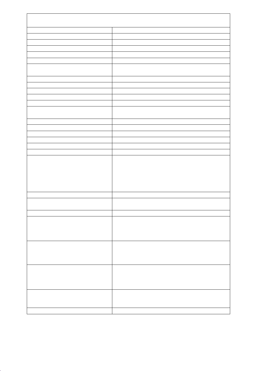
SpecIficaftioDHS
CRT Size
Dot-pitch
Phosphor
Surface treatment
Input signals Video signaling
Signal level
Sync signal
Horizontal Frequency Range
Vertical Frequency Range
Preset mode
Video MaximumPixel Clock
Resolution 1280 do1s(H) X 1024 lines (V) at 60 Hz*
Viewable Image Size Factory preset
(H X V, Diagonal) Full scan (Typical)
Display Color
Connectors Signal
Power supply
Input power
Power consumption
Controls Front Power ON/OFF, Q], a, B, H] keys
On screen display Contrast, Brightness, Size & Pos (H. Position, H. Size, V. Position,
Tilt/swivel
Dimensions (W x H x D)
Weight (monitor only)
Approvals
17" CRT (16.0740.6 cm Viewable Image Size) Flat Square
0.27 mm
RGB short persistence (Hi-EU RED)/Dark TINT
Advanced AGRAS(Anti-Glare, anti-Reflective and Anti-Static) Coat
RGB analog
0.7 Vp-p (without sync, signal), 1.0 Vp-p (with sync, signal)
HA/ separation (TTL level), H/V composition (TTL level),
Sync-on-green
Allowable Frequency Range: 30.0 kHz to 70.0 kHz
Allowable Frequency Range: 50.0 Hz to 180.0 Hz
1 preset and 7 reservation (See page 16)
108 MHz (typ.)
11.81" X 8.86", 14.8" Diagonal **
12.80" X 9.60", 16.0" Diagonal **
Analog input, unlimited number of colors ***
15-pin mini D-Sub connector (female pins)
CEE 22 type 3-pin connector
100 to 240V AC (50 or 60Hz)
110W typ. / < 15W stand-by, < 4W sleep mode (See page 14)
V. Size), Geometry (V. Pincushion, Side Pincushion Balance,
Trapezoid, Par^letogram), Rotation (Tilt), Color Temp, (9300K +
8 MPCD, 7500 K, 6500K, 5000K, User color adjustment). Recall,
Video Level select (0.7V/1,0V), Language select, OSD Position,
Degauss, Signal, Monitor Self Test
13® up, 4“ down, 90° each to right and left
(16.1" X 16.4" X 15.0")
410 mm X 416 mm x 382 mm
17.2 kg (37.9 lbs)
UL1950, CSA 22.2 No.950, TUV/GS, NORDIC, DHHS,
FCC Class B, CE / CISPR 22-B(EN55022), VCCI Class B,
MPR II, TCO ’92, / NUTEK, ISO 9241-3 (Ergonomics)
/ -e(Colors), VESA DPMS, Energy Star*
Standard
Environmental conditions
Operating Temperature
Humidity
Altitude
Storage Temperature
Humidity
Altitude
Windows*95 Plug & Play
Note:
*The on-screen image may flicker if the display is operated with the Vertical freq. under 60 Hz
“Section on signal timing used, see page 15 .
*** Number of colors depends on the Video Board used, memory installed, and RAMDAC
(Random Access Memory Digital to Analog Converter).
Specifications and design are subject to change without notice.
This product may be subject to export regulations.
1 detachable signal cable for VGA,SVGA.
1 detachable AC power supply cord.
Tilt & Swivel base attached.
Operating Instructions, Warranty card
5 to 35*0(41 to 95*F)
5 to 90% (no condensation)
10,000 ft
-20 to +60*C(-4to140°F)
5 to 90% (no condensation)
40,000 ft
VESA DDC1/2B meets Windows* 95 Plug & Play Requirements
_4 _
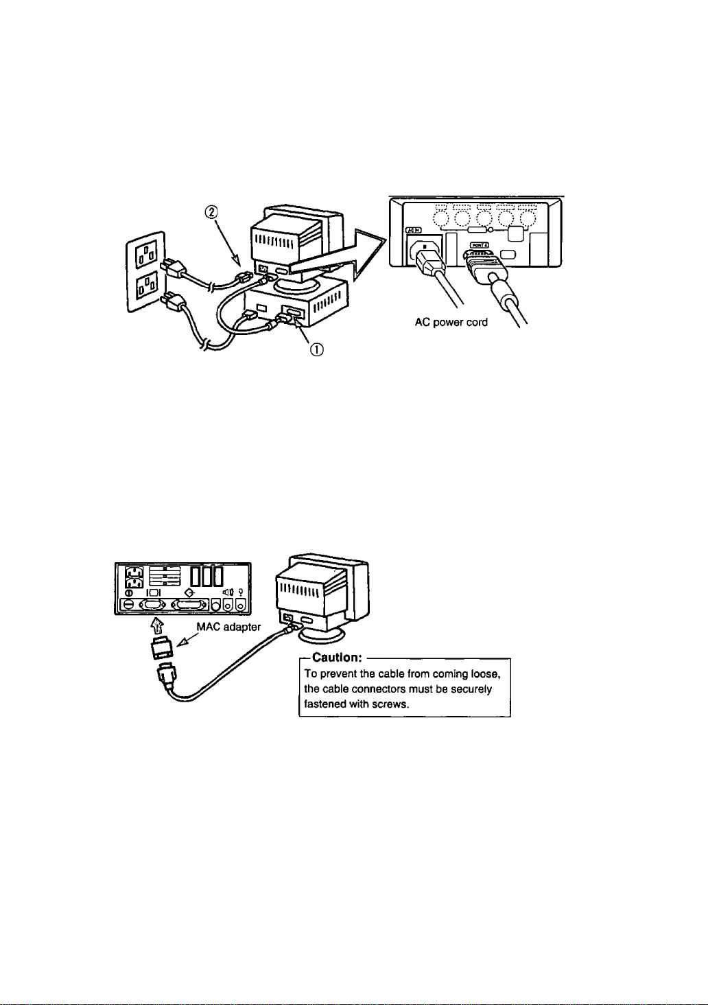
^Connecting Procedures
Turn off your computer.
Connect the signal connectors as shown below.
Turn the monitor on, then turn on the computer.
A. IBM PS/2 or compatible models
Rear view
0 Connect the supplied signal cable to the
monitor's port.
0 Connect the other end of the AC power cord
to a grounded power outlet.
B. Apple computer
Use a UNIMAC-82D MAC adapter.
Panasonic MAC adapter
If you need an adapter and one is not provided
by your dealer,
call 1-800 PANASYS (1-800-726-2797).
15-pin mini
D-Sub cable
^Connection of AC Power Suppiy
If the AC power supply voltage is in the range 100 to 240V, either 50Hz or 60Hz frequency can be
used.
There is no AC100V/240V selector switch as selection is automatic.
Precaution:
• In order to use the display unit safely, use a power cord that is properly grounded.
• AC plug cords for the following countries are supplied in the same package.
For use in other countries, make sure the AC cord meets the safety standards of each country.
U.S.A
Canada
.........
......
UL
CSA
— 5 —

Pin Assignmenit
Follow the instructions below to connect the SL70 to a computer.
A. Signal connector: 15-pin mini O-Sub (PS/2 or PC/AT compatible model)
Connect the signal cable to the 15-pin mini D-Sub connector on the display unit.
B. Signal connector: 15-pin D-Sub (Apple computer)
Convert a MAC 15-pin D-Sub connector to a 15-pin mini D-Sub connector using
a Panasonic MAC adapter, and connect it to the 15-pin mini D-Sub connector
on the display unit.
< REAR PANEL >
Pin assignments of 15-pin mini D-Sub connector
Pin number
1
2
3
4
5
6
7
8
9
10
11
Signal name
Red video signai
Green video signal
Blue video signal
Ground
Ground*
Ground for Red video signal
Ground for Green video signal
Ground for Blue video signal
Unused
Ground
Ground
12 SDA* (Bi-directional Data)
13
14
15
^ “VESA”s Display Data Channel (DDC) Standard.
Horizontal sync, signal
Vertical sync, signal
SCL* (Data Clock)
-6 -
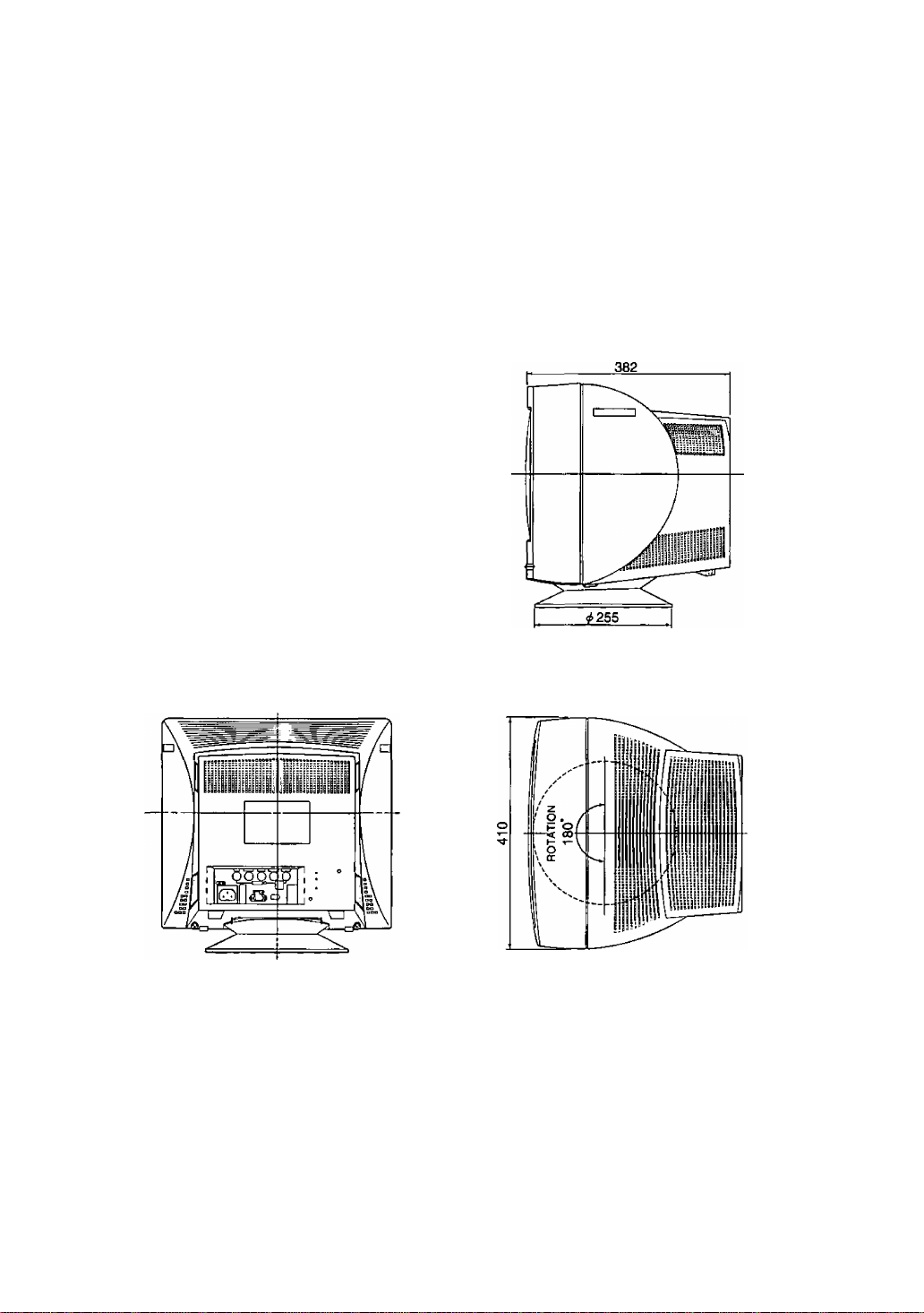
External View
Dimensions
Width : 410 mm (16.1")
Height: 416 mm (16.4")
Depth : 382 mm (15.0")
Base diameter; ^255 mm (^10.0")
Height without stand : 374 mm (14.7")
410
Pan/Tilt range
Up
Down
Left, right
13 degrees
4 degrees
90 degrees each
-7 -
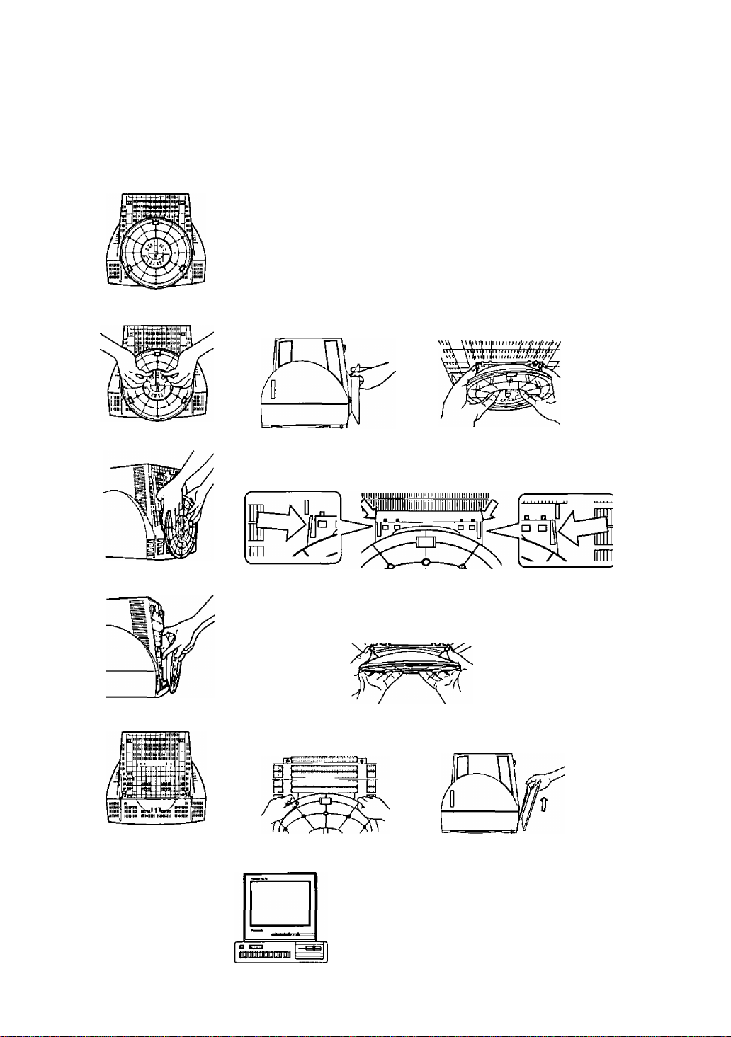
Observe the following instructions if the unit is to be used with the display
stand removed. Repeat this procedure in the reverse order if the display
stand is to be reattached.
1. Removing the monitor stand
Lay the screen down onto a soft object (cushion,etc.) to
avoid scratching.
[H Grasp the bottom of the display stand as indicated in the illustration.
I Apply pressure with your fingers to the area shown in the illustration
and lift the stand slightly in an upward direction.This will release the
lock.
Once the lock has been released,remove your fingers and
firmly lift upwards at an angle.
This will separate the stand from the main unit.
After the display stand has been removed, store It for future use.
2. Instailation
Place the unit on top of the computer to
be used or on a tabletop.
Store the display stand for future use.
-8 -
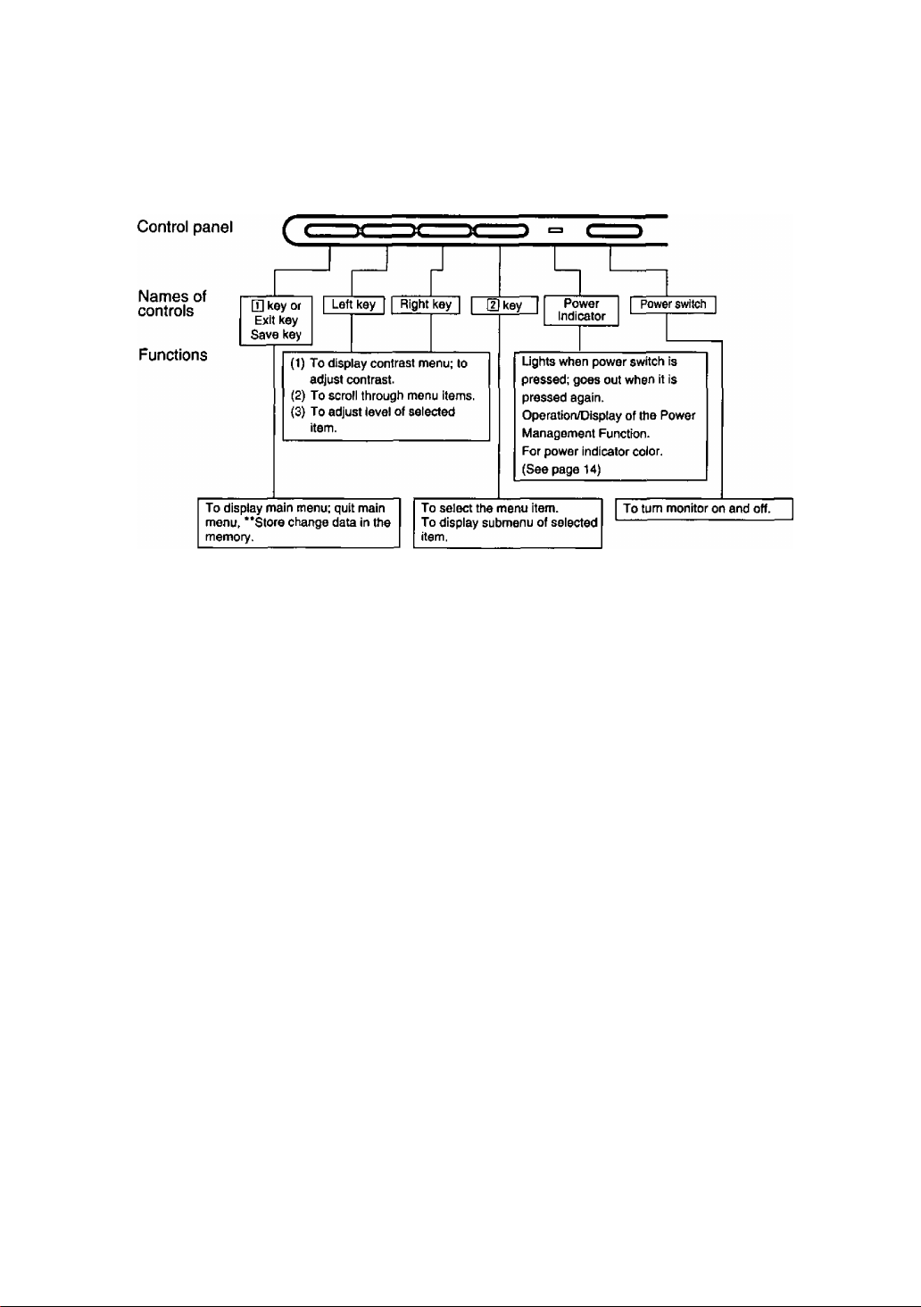
00“Scireeini AcSJusIlmeini
[Basic operation]
E <1 > [2]
For a detailed description of the functions of the D] key, left key, right key. and [2] key,
refer to page 10-13.
Since contrast is the most commonly adjusted parameter, we have provided direct
access to this menu item. By pressing the S or B key during normal operation the
contrast menu is displayed instantly.
O
- 9 -
Operation
< Onscreen Display>
Monitor Self Test
See figure A.
No S igna
fH —.—kHz
fV —Hz
See figure B.
Error
fH 74.9kHz
fV 60.0 Hz
Menu
The adjusted items are represented by
icons.
When the Q] key is pressed, the menu
screen appears.
Use the 3 • B keys to move the cursor
to the item to be adjusted, then press
the [U key to call the adjust menu.
E3 -Xi- E
O SI
111 JP\
Contrast
a
s
< Function and Operation>
This display indicates that the monitor is
operating normally. When one of the following
conditions occurs, press one of the 4 front
panel keys to call the appropriate display.
1) No Signal (The computer is not connected or
the mains power to the computer is
disconnected). See figure A.
2) The horizontal or vertical sync, signal are
outside of the permitted range (the value of
the horizontal sync, signal will be displayed in
red and the value of the vertical sync, signal
will be displayed in white). See figure B.
[D3
S
0
m
n
.a
Q
D
Contrast
Brightness
Size & Pos.
H. Position
H.Size
V. Position
V.Size
Geometry
V.Pincushion
Side Pin. Bai.
Trapezoid
Paraileiogram
Rotation
Coior Temp
Recali
Video Level
Language
OSD Position
Degauss
Signai
3
23
o
o
O
;©
?t
§!1
F\
a Contrast adjustment
Contrast
100
3 :[I]
^ Brightness adjustment
B ri g t n e s s
50
0 -.m
Adjust the screen contrast to match the
brightness level in the room. Press the B key to
make the image lighter, the H key to make it
darker.Pressing the H] key toggles between
brightness and contrast.
Direct operation: Even if the menu screen does
not appear, the contrast can be adjusted by
pressing the 3 or B key.
If the H and B keys are pressed at the same
time on the Contrast adjustment screen, the
maximum level (100) will be set.
Contrast adjusts the white level.
Adjust the brightness to match the brightness
level in the room. Press the 3 key to make the
background darker, the B key to make it lighter.
Pressing the H] key toggles between brightness
and contrast.
Brightness adjusts the black level.
* If the 3 and B keys are pressed at the same
time on the Brightness adjustment screen, the
standard level (50) will be set.
-10-

< Onscreen Display >
Size & Pos.
< Function and Operation >
Press the [2] key to select the Horizontj
Vertical Size adjustments.
FB] Horizontal Position
adjustment
H. Position
50
[D] B Q m :[2
Horizontal Size
adjustment
H. Size
CB] B @ cn :[5]
fB) Vertical Position
adjustment
V. Position
50
l~B3 @ @ cm :
il Position / Horizontal Size / Vertical Position /
The horizontal position of the image can be
adjusted. Press the 3 key to move it to the left,
the B key to move it to the right.
* Press the □ key to save the adjustment.
The horizontal size of the image can be adjusted.
Press the 3 key to make the image smaller, the
H key to make it larger. Then press the [L key to
save the adjustment.
* Setting the image in the center of the screen will
make the size adjustment easier.
The vertical position of the image can be
adjusted. Press the 3 key to move it downward,
the B key to move it upward.
* Press the Q] key to save the adjustment.
in Vertical Size adjustment
The vertical size of the image can be adjusted.
Press the 3 key to make the image smaller, the
B key to make it larger. Then press the Q] key to
save the adjustment.
* Setting the image in the center of the screen
O B B m :(2
will make the size adjustment easier.
FI Geometry
Press the [2] key to select the Vertical Pincushion / Side Pincushion Balance / Trapezoid
/ Parallelogram adjustments.
FT Vertical Pincushion adjustment
V. Pincushion
50
UCian -ÌÈ
The image can be corrected for barrel distortion.
Press the 3 key to decrease the barrel distortion
of the image, the B key to increase it.
-11
-

< Onscreen Display>
< Function and Operation>
Q Side Pincushion Balance
Side Pin. Bal.
50 iMiaiHflBa
TldCXD
r\ Trapezoid adjustment
Trapezoid
50 I'.aaiaiBF.ti.i'j
na Q/7 :d]
O Parallelogram adjustment
Parallelogram
50 liiaMBiiaiiH —I
YICLCXD :[2]
Oi Rotation (Image tilt)
adjustment
Rotation
50
The image can be corrected for barrel balance
distortion. Press the S key to expand to the left of
the image, the B key to expand to the right it.
The image can be corrected for trapezoidal
distortion.
Press the a key to make the top edge narrower,
the B key to make the bottom edge narrower.
The image can be corrected for parallelogram
distortion.
Press the a key to collapse the parallelogram to
the left, the B key to collapse it to the right.
Use this to adjust for tilt on the screen.
Press the a key to rotate the image slightly
counterclockwise, the B key to rotate the image
slightly clockwise.
‘Pressing the a and B keys simultaneously
adjusts rotation to its factory preset level.
01 Color Temp
Color Temp
511 2 3 4 5
9300K+8
User Color adjustment
R100 C
G 80 [SEIEü3»EEn
ww
R-B :m
Note:Record the initial values of R,G and B
here before making any adjustments:
R ( Red) __________________
G { Green ) __________________
B ( Blue )
_________________
The white in the image can be adjusted.
1) Use the
MPCD, 2: 7500 K, 3: 6500 K, 4: 5000 K or 5 :
the user’s preferred color.
2) If" 5 : user’s color" is selected, d] ” appears
in the lower right of the On-Screen Display.
Press the front [U key to call the User Color
adjustment screen.
The white in the video image can be adjusted to
the user’s preferred color.
1) Use the [H key to select R (red) or G (green)
or B (blue).
2) Use the a • B keys to adjust the color as
desired.
* Recall of the user’s color is not possible, so
make a note of the initial setting before
adjusting.
-12 -
a • B
keys to select 1: 9300 K + 8

< Onscreen Dìsplay> < Function and Operation>
<0 Recall
□]: Yes
Recall
OK ?
NO :[2]
To return to the initial settings (the settings at the
time of factory shipment).
1) When the Q] key (Yes) is pressed, the settings
are recalled and the menu screen returns.
(Recall = return to settings at time of factory
shipment.)
2) When the H] key (No) is pressed, the menu
screen returns without the settings being
recalled (the settings return to what they were
immediately before the recall).
* If no operations are performed for about 30
seconds, the screen goes off without recall.
i© Video Level
Vide Level
0.7 V
0.7/1V :[I]
7^ Language selection
Language
OEU FRA rana
ITA ESP
llg OSD Position
□ ^ I 1^1 I
The video input signal level can be matched to
the computer being used. Either 0.7V or 1 .OV
can be selected with the H] key.
Note : 0.7V is typical.
(If wrong level is selected image may be too dim
or too bright.)
The language used by the On-Screen Display
can be selected can be selected with the “S”
and “B" keys from among German, French,
English, Italian and Spanish.
DEU: German
FRA: French
ENG: English
ITA ; Italian
ESP: Spanish
It is possible to adjust the position that the on
screen panel is to be displayed.
The panel will rotate in a counter-clockwise
direction every time the [I] key is pressed.
f\ Degauss
Degaussing operation can be selected.
After this is selected, the degaussing action takes place for approximately 6 seconds.
Key operation is not possible while demagnetization is performed.
El Signal
1024 X 768
fH 60.2kHz
fV 74.0 Hz
Resolution (1024 X 768) will only appear if
timing is preset or reservation.
Signal displays the computer's approximate
horizontal sync frequency (fH) and vertical
sync frequency (fV).
If the fH or fV are outside the specified range
then the Monitor Self-Test function will auto
matically display the Signal Error menu (See
page 10).
-13 -
Power Mamiagemeinlí Sysíem
This monitor conforms to the VESA DPMS standard.
This function can suppress power consumption by the display unit.
The computer and video board being used must also conform to the VESA DPMS
standard.
* Consult the Operation Manuals for the hardware being used.
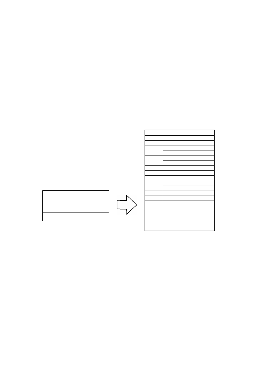
Modes change in response to input signals as indicated in the table below.
APM State Screen status
ON STATE with display green normal
STAND-BY without display
SUSPEND
OFF STATE
without display
without display yellow < 4 watts
Power
Indicator
color
yellow
yellow < 15 watts < 3 sec.
Power
consumption
< 15 watts
Return time
—
< 3 sec.
< 20 sec. OFF
video horizontal sync.
ON ON ON
OFF OFF
OFF
Input signals
ON OFF
OFF OFF
Caution
How to release the system from the power management function.
1) Read the Operation Manuals for the hardware you are using.
2) Press one of the □ - @ - B • [2] keys on the front panel.
The No Signal screen appears, and the monitor side power management function is
released (only in OFF STATE).
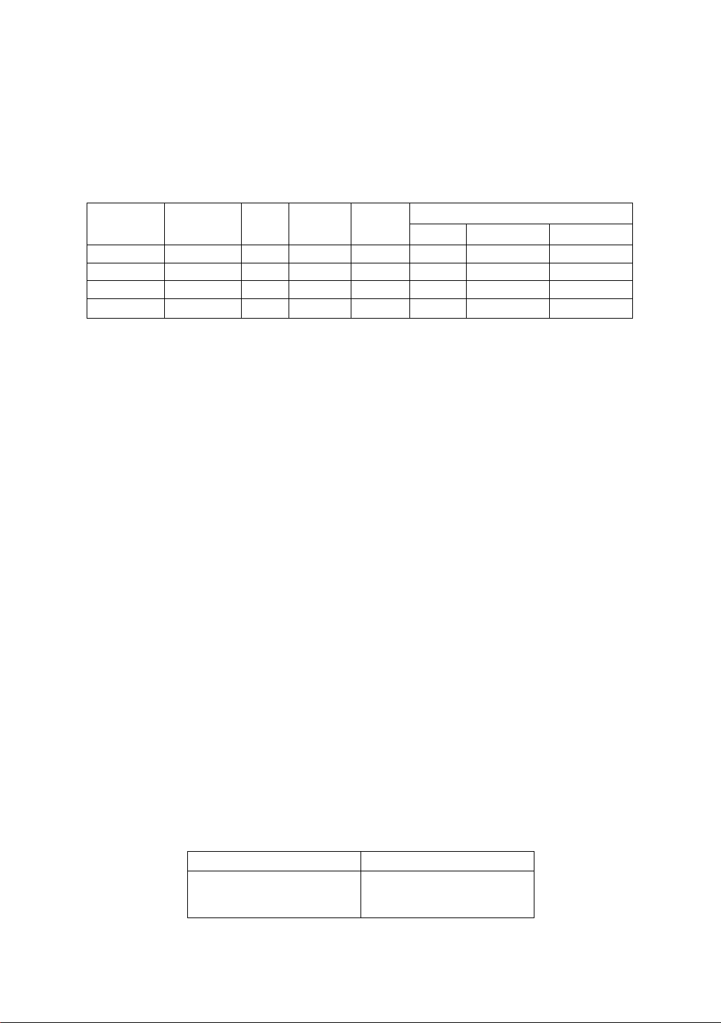
IVSemooes
vertical sync.
ON
This display has two types of memory to store the data sets that control the on-screen
image. The first type of memory is the Preset Memory which is set by the factory. The
second type is the User Memory which is set by the user. Both memories store the
Horizontal Size, Vertical Size, Horizontal Position, Vertical Position, Vertical Pincushion,
Side Pincushion Balance, Trapezoid and Parallelogram adjustments of the displayed
image.
Preset Memory
There are 1 preset (7 reservation) timings that are set by the factory. The preset timing will automatically size
and center the image with video boards which use these timings. Please see page 15 for Timing Specifications.
User Memory
• There are 13 memory locations that allow for user timing. The image size, position, geometric distortion are
adjusted by the user. Please see page 16 and 17 for recommended timings that the display supports.
• If the User Memory is completely full, and a new set of data is saved, the oldest data set in the User Memory
will be deleted.
• The User Memory has priority over the Preset Memory.
• When the user timing is input, the Vertical, Horizontal frequencies and sync polarities of the signal are
compared with the previous data stored in memory. The input signal will be stored as a new data set if one
of its parameters is different from the previous stored one.
• The new input signal must have a frequency difference greater than that shown in the table below or a
different sync, polarity from that already stored. If the new timing data includes frequency changes greater
than those shown in the table below or sync, polarity changes, a new user memory setting wilt be stored. If
the frequency difference is smaller than that of the chart and the sync, polarities are the same, the existing
settings will be retained.
Horizontal frequency
Low 30 kHz ± 0.4 kHz
to
Hi 70 kHz ±1.0 kHz
Vertical frequency
Low 50 Hz ± 0.6 Hz
to
Hi 180 Hz ±1.8 Hz
Please note if the timing does not meet the display specifications, the size and position adjustment may not
appear as desired. Be sure the horizontal and vertical timing are within the monitor specification range.
See page 15 for Timing Specifications. Pages 16 and 17 for preset, reservation and recommended timing.
-14 -

Separate Sync.
Horizontal
Vertical
H/V Composite Sync.
Horizontal
Vertical
—ij
B
“LIT
i£4-
~U—
innnna
I Video
Vlideo
S
Vlideo
HhM-—s >\^\
Jinrinr
L_a.
I* '' -|
^
K-^
D
...............
IT
Vlideo
U
:h
1nnri
Sync, on Green
Horizontal
Vertical
l-Tl
ilLn
____ _
JUS L O .I.R.I.
- 15 -
nnntt'"iH/lnnr&
-------------------s-----
Preset timing*
VESA 1024 x 768 @75 Hz
Dot clock
fH
_
A
H-Period
F H-Blanking
C
О
В
N
о
X
<5
u
0
>
_
C
О
N
О
I
О
a>
>
n
c
о
N
О
X
о
<D
>
Note: All modes are Non-Interlaced.
* Factory Presets have exact size & centering.
** Factory Reservation have approximate size & centering.
*** Requires the use of Optional Mac Adapter UNIMAC-82D.
H-Sync width
H-Back porch
c
D
H-Active
E H-Front porch
fV
P V-Period
U V-BIanking
V-Sync width
Q
V-Back porch
R
S V-Active
T V-Front porch
Sync polarity (H/V)
Dot clock
fH
A
H-Period
F H-Blanking
В H-Sync width
H-Back porch
c
D H-Active
H-Front porch
E
fV
P V-Period
U V-Blanking
V-Sync width
Q
V-Back porch
R
S V-Active
V-Front porch
T
Sync polarity (H/V)
Dot clock
fH
A H-Period
F H-Blanking
H-Sync width
В
H-Back porch
C
D H-Active
H-Front porch
E
fV
P V-Period
U V-Blanking
V-Sync width
Q
V-Back porch
R
S V-Active
V-Front porch
T
Sync polarity (H/V)
78.7500 MHz
60.023 kHz
16.660 us (1312 dots)
3.657 us ( 288 dots)
1.219 us ( 96 dots)
2.235 US ( 176 dots)
13.003 us (1024 dots)
0.203 us ( 16 dots)
75.029 Hz
13.328 ms (800lines)
0.533 ms ( 32lines)
0.050 ms ( 3lines)
0.466 ms ( 281ines)
12.795 ms(768lines)
0.017 ms ( nine)
Positive/Positive
VESA 800x600 @75 Hz
49.5000 MHz 57.2832 MHz 75.0000 MHz
46.875 kHz 49.725 kHz 56.476 kHz
21.333 us (1056 dots)
5.172 us (256 dots) 5.587 us ( 320dots) 4.053 us ( 304dots)
1.616 us ( 80 dots)
3.232 us (160 dots) 3.910 us ( 224dots)
16.162 us (800 dots)
0.323 us( 16 dots)
75.000 Hz 74.550 Hz
13.333 ms (625 lines)
0.533 ms ( 25 lines)
0.064 ms ( 3 lines)
0.448 ms ( 21 lines) 0.784 ms ( 391ines)
12.800 ms (600 lines)
0.021 ms ( nine ) 0.020 ms ( nine )
Positive/Positive Negative/Negative Negative/Negative
Reservation timing**
MAC(l9')lQ24x768 @ 75H;r**
80.0000 MHz
60.241 kHz
16.600 us (I328d0ts) 15.630 us (1688dots) 26.413 us ( 832dots)
3.800 us ( 304dots) 3.778 us ( 408dots) 6.095 us ( 192dots)
1.200 us ( 96dots)
2.200 us ( 176dots)
12.80CTus(l024doTs)
0.400 us ( 32dots) 0.444 us ( 48dots) 0.762 us ( 24dots)
74.926 Hz 60.020 Hz 84.135 Hz
13.346 ms ( 804lines) 16.661 ms (1066lines) 11.886 ms (450lines)
0.598 ms ( 36lines) 0.656 ms ( 42lines) 2.641 ms (lOOlines)
0.050 ms ( 3lines) 0.047 ms ( 3lines) 0.079 ms ( 3lines)
0.498 ms ( 30lines) 0.594 ms ( 38lines) 1.638 ms ( 621ines)
12.749 ms ( 7681ines)
0.050 ms { 3lines) 0.016 ms ( Itine ) 0.924 ms ( 35lines)
Negative/Negative Positive/Positive Positive/Negative
-16 -
Reservation timing**
VGA 640 x 480 @60 Hz
25.1750 MHz
31.469 kHz 37.500 kHz
31.778 us (800 dots)
6.356 us (160 dots)
3.813 us ( 96 dots)
1.907 us ( 48 dots)
25.422 us ( 640 dots) 20.317 us ( 640dots)
0.636 us ( 16 dots) 0.508 us ( 16dots)
59.940 Hz 75.000 Hz
16.683 ms (525 lines)
1.430 ms ( 45 lines) 0.533 ms ( 20lines)
0.064 ms ( 2 lines) 0.080 ms ( 3lines)
1.049 ms ( 33 lines)
15.253 ms (480 lines)
0.318 ms ( 10 lines) 0.027 ms ( nine)
Negative/Negative Negative/Negative
Reservation timing**
M/\C(16') 832 x624 @ 75 Hz*“
20.111 us (1152dots) 17.707 us (1328dots)
1.117 us ( 64dots) 1.813 us ( 136dots)
14.524 us ( 832dots)
0.559 us ( 32dots)
13.414 ms { 667lines)
0.865 ms ( 43lines)
0.060 ms ( 3lines) 0.106 ms { 6lines)
12.549 ms ( 6241ines) 13.599 ms (768lines)
VESA1280x1024 @60Hz
108.0000 MHz
63.981 kHz 37.861 kHz
1.037 us ( 112dots)
2.296 us ( 248dots)
11.852 us (1280dots)
16.005 ms (I024lines)
VESA 640x480 @75 Hz
31.5000 MHz
26.667 us ( 840dots)
6.349 us ( 200dots)
2.032 us ( 64dots)
3.810 us ( 120dots)
13.333 ms ( 500lines)
0.427 ms ( 16lines)
12.800 ms ( 480lines)
VESA1024x768 @70Hz
1.920 us { 144dots)
13.653 us(l024dots)
0.320 us ( 24dots)
70.069 Hz
14.272 ms(806lines)
0.673 ms ( 381ines)
0.513 ms ( 29lines)
0.053 ms ( 3lines)
Recommended timing
640x350® 84 Hz
31.500 MHz
1.270 us ( 40dots)
4.063 us ( 128dots)
20.317 us ( 640dots)
9.244 ms (350lines)
 Loading...