

Page 1
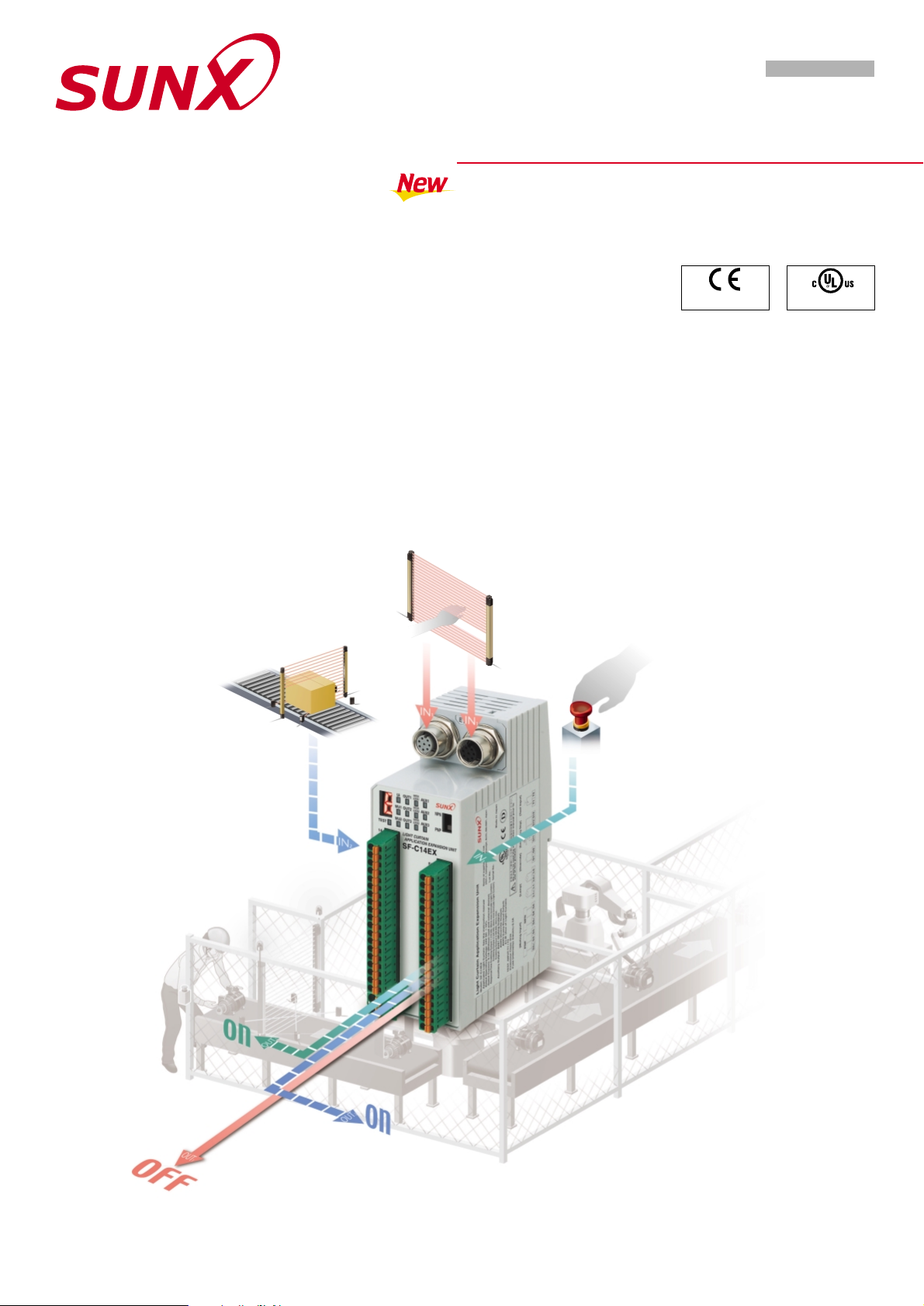
APPLICATION EXPANSION UNIT FOR SF4B SERIES
Expanding the possibilities
for light curtains
Muting & Emergency stop & Semi-conductor output
SF-C14EX SERIES
SENSOR OPTION
Light curtain
SF4B
Muting input
Conforming to
EMC Directive
Approved Listing
Emergency stop
input
Page 2
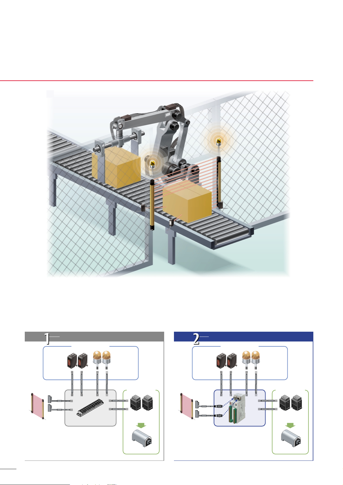
Building
method
Using SF4B series functions
1
Built-in muting control circuit. Light curtain and emergency stops can
be controlled independently to achieve partial equipment stoppages.
Building of muting control circuits is easy
The method used to build the safety circuit is selectable
When the SF4B series of light curtains is used, the muting control circuit can be built at low cost. The newly-released SF-C14EX application
expansion unit allows the light curtain, muting sensors and muting indicators to be connected together directly, so that muting control circuits
can be built very easily.
SF4B
series
Light curtain connector connection.
Terminal blocks for peripheral circuits available.
Motor, etc.
External device
(Force-guided relay, etc.)
Muting
sensor
Muting
indicator
Muting
sensor
Muting
indicator
Low cost!
Saves space!
No safety relay unit needed
Muting control
Safety output
Terminal blocks
Building
method
Using the SF-C14EX internal circuits
SF4B
series
Motor, etc.
External device
(Force-guided relay, etc.)
Less wiring!
Reduced maintenance!
Muting control
Safety output
SF-C14EX
Exclusive connection
cable for SF-C14EX
Page 3
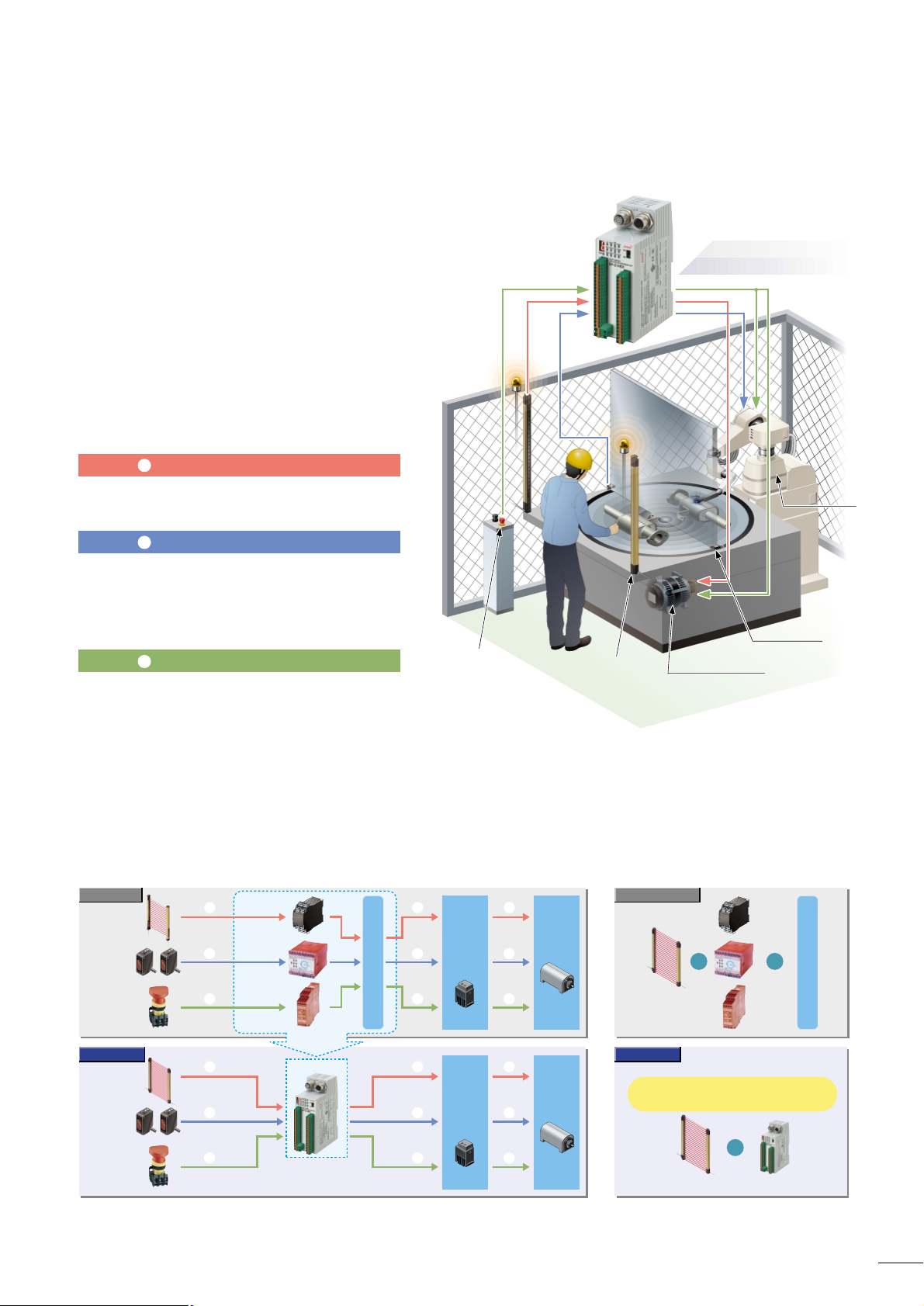
SF-C14EX
2
Three safety circuit systems packaged into a single unit!
Three safety circuit systems 1 Light curtain output circuit, 2 Muting control circuit, and
3 Emergency stop circuit are packaged into a single unit. Functions that require multiple
safety relay units and muting control units can be concentrated into a single unit, which
results in large space savings, less wiring and less installation work.
14 ms
10 ms
20 ms
20 ms
High-speed response 14 ms
(Including light curtain)
Avoids the response delays that occur when
using more than one safety relay unit, and
greatly reduces the light curtain safety
distance and improves ease of working.
Safety circuit: Linked to light curtain beam received / interrupted status (partial stop)
● When the light curtain is interrupted (when an workpiece enters
or a person intrudes), this circuit switches off (open) the safety
output and stops the turntable.
● ● If an workpiece enters when the turntable has stopped normally,
(muting conditions are achieved), this circuit allows the robot to
operate.
If an workpiece enters while the turntable is turning (muting
conditions are not achieved), this circuit switches off (open) the
safety output and stops the robot.
● When the emergency stop button is pressed, this circuit switches
off (open) the safety output and stops all equipment (turntable
and robot).
Safety circuit: Linked to emergency stop input (all stop)
Safety circuit
: Linked to muting control (partial stop)
Muting
sensor
Emergency
stop button
Light curtain
Previous model
SF-C14EX
Previous model
External
contactor
Force-
guided
relay, etc.
Motor
Muting
sensor
Emergency
stop button
SF4B series
Motor
Customer's logical connection circuit
Safety relay
unit
Muting unit
Safety relay
unit
SF-C14EX
Saves space!
Less wiring!
Reduced maintenance!
Saves space!
Less wiring!
Reduced maintenance!
1 Light curtain output circuit 2 Muting control circuit 3 Emergency stop circuit
3
2
1
3
2
1
3
2
1
3
2
1
3
2
1
3
2
1
External
contactor
Customer's logical connection circuit
Total 14 ms
Including light curtain response time
High response speed of 14 ms!
Greatly reduced safety distance!
High response speed of 14 ms!
Greatly reduced safety distance!
Applications expanded even further!
Three safety circuit systems can be controlled independently
so that equipment can be stopped all together or partially.
1 23
Emergency stop button
Turntable
Motor not using muting
SF4B
Limit switch
For muting input
Robot
Motor using m Motor using muting
Robot
Motor using muting
1
2
3
()
Force-
guided
relay, etc.
()
Motors that use muting control and those that
do not use it can be controlled independently!
Controls the motors that use muting control (robots) and
the motors that do not use muting control (turntables) with
a single unit.
When the workpiece comes in, the turntable can be stopped
and the robot can keep operating condition, to protect the
safety of the operator and to maintain productivity.
SF-C14EX controls three safety
output systems using only a single unit!
Page 4

For example, if muting control is set to be carried out in
accordance with the height of the workpiece, the machinery
stops when any of the beam channels are interrupted above
the workpiece.
During muting control (line moving)
Line stopped
NPN
PNP
NPN
PNP
Polarity selection
switch
NPN
PNP
NPN
PNP
Auxiliary output
Safety output
Lead wire
Flat-tipped
screwdriver
Release
button
Lead wire insertion hole
Ferrule (sleeve) terminal
(Please prepare separately.)
Uses a spring method
Internal
relay replacement
is unnecessary
Adoption of semiconductor output
Blown lamp
display
Removable!
Blown lamp!Blown lamp!
* A Handy-controller cannot be used with the
SF-C14EX-01.
Handy-controller
SFB-HC
Function Operation
Auxiliary
output 1
Auxiliary
output 2
Auxiliary
output 3
Auxiliary
output 4
Muting output
Override output
Blown lamp output
Light curtain
auxiliary output
ON when the muting
function is invalid
ON when the override
function is invalid
ON when the light curtain is
in light interrupted condition
ON when the muting
indicator is normal
Equipped with blown lamp
output for muting indicator
If a lamp in one of the two muting indicators
that are connected to the unit blows, a
warning is output. It is possible to replace
the lamp before both lamps blow and the
equipment stops. In addition, auxiliary
output that is linked to the muting function,
override function and light curtain control
output is also available.
Supports both PNP and NPN
polarities
A single model can be used for PNP / NPN
input switching, reducing the number of
parts that need to be registered.
Detailed functions that support easier ‘installation’ and ‘maintenance’
Compatible with a Handy-controller for easy setting
Removable terminal blocks reduce
maintenance time
Removable terminal
blocks are used.
This reduces the
work required for
reconnecting wiring
during maintenance.
Equipped with a digital indicator so that error details can
be understood at a glance!
If a problem should occur, the same output
(OFF signal) as when the object was
detected is maintained in order to ensure
safety, and the details of the error appear on
the digital display.
SF-C14EX only
A variety of other functions
can be selected
•
•
•
•
•
Semiconductor output
reduces running costs!
Semiconductor output is used for safety
output. This means there is no need to
periodically replace safety relays.
Easy setup requiring no
torque control
A spring method is
used for the terminal
blocks for connections
other than to the light
curtain. There is no
need to control
tightening torques for
these terminal blocks.
•
•
•
•
Emission intensity control function
Setting monitoring function
Protection function
Copy function
Muting indicator diagnosis setting
Can be used to set a wide variety
of functions together with the
SFB-HC Handy-controller
Separate muting control function for
each beam channel
The SFB-HC Handy-Controller (optional)
can be used to carry out muting control for
specified beam channels only.
Any valid beam channels can be selected!
The SF4B series incorporates a fixed
blanking function
The SF4B series is equipped with a fixed blanking function that allows specific beam
channels to be selectively blocked, without causing the control output (OSSD) to output the
OFF signal.
Non-specified beam channels can be deactivated !
The SF4B series incorporates a floating blanking function
1, 2 or 3 non-specified beam channels can be deactivated.
Auxiliary output has selectable output configuration
The output configuration of the auxiliary output can be changed.
3
Page 5

SF-C14EX
ORDER GUIDE
Appearance Model No.
Up to control category 4
Description
SF-C14EX
Application expansion unit
Light curtains connection cable
Environmental
resistance
Connectable light curtain
Applicable standard
Control category
Supply voltage
Current consumption
Muting indicator output
Material
Connection terminal
Weight
Protection
Ambient temperature / Ambient humidity
Dielectric strength voltage / Insulation resistance
Vibration resistance / Shock resistance
Safety output
Safety output 1
Safety output 2
Safety output 3
Auxiliary output
Auxiliary output 1
Auxiliary output 2
Auxiliary output 3
Auxiliary output 4 (Note 4)
Operation mode
(Output operation)
Operation mode
(Output operation)
Response time
Protection circuit (Short-circuit protection)
Protection circuit (Short-circuit protection)
SF4B series
IEC 61496-1, UL 61496-1, EN 61496-1, JIS B 9704-1
Applicable to Category 4 based on ISO 13849-1 (EN 954-1, JIS B 9705-1)
24 V DC 10 % Ripple P-P 10 % or less
0.2 A or less (Excluding light curtain and other external connecting device)
Incorporated
Protection circuit (Short-circuit protection)
Incorporated
Applicable muting indicator: 24 V DC, 3.6 to 30 W (per unit)
Incorporated
Enclosure: IP40, Terminal: IP20
10 to55 C 14 to131 F (No dew condensation or icing allowed), Storage: 25 to70 C13 to 158 F / 30 to 85 % RH, Storage: 30 to 95 % RH
1,000 V AC for one min. between all supply terminals connected together and enclosure / 20 MΩ, or more, with 500 V DC megger between all supply terminals connected together and enclosure
10 to 55 Hz frequency, 0.35 mm 0.014 in amplitude in X, Y and Z directions for two hours each (in power OFF state) / 30 G acceleration in X, Y and Z directions for three times each (in power OFF state)
Enclosure: ABS
Detachable spring gauge terminal
Net weight: 250 g approx.
SPECIFICATIONS
Item
SF-C14EX
Model No.
AppearanceType DescriptionModel No.
Used for connecting to the light curtain and to SF-C14EX control unit 8-core
extension cable with connectors on both ends (SFB-CCJ10E/CCJ10D)
Two cables per set for emitter and receiver,
Cable outer diameter: "6 mm "0.236 in
Max. outer connector diameter: "14 mm "0.551 in
Cable color: Gray (for emitter), Gray with black line (for receiver)
Min. bending radius: R6 mm R0.236 in
Exclusive
connection
cable for
SF-C14EX
Length: 10 m 32.808 ft
Net weight 1,200 g approx. (1 cable)
Length: 0.5 m 1.640 ft
Net weight 95 g approx. (2 cables)
Length: 5 m 16.404 ft
Net weight 620 g approx. (2 cables)
SFB-CB05-EX
SFB-CB5-EX
SFB-CB10-EX
Note:
If extending cables between light curtain units, be sure to use the SFB-CCJ10E (for emitter; cable length 10 m 32.808 ft) and the SFB-CCJ10D (for receiver;
cable length 10 m 32.808 ft). The cable can be extended within 30 m 98.425 ft (for emitter / receiver) when two light curtains are connected with series
connection, within 20 m 65.617 ft when three light curtains are connected with series connection. The cables cannot be extended when connecting in parallel.
()
PNP open collector transistor 2 outputs3 or NPN open collector transistor 2 outputs3 (selectable using a slider switch)
<When PNP output is selected>
• Maximum source current: 200 mA or less
• Applied voltage: same as supply voltage
(between the safety output and
V)
• Residual voltage: 2 V or less (at 200 mA source current)
<When NPN output is selected>
• Maximum sink current: 200 mA or less
• Applied voltage: same as supply voltage
(between the safety output and 0 V)
• Residual voltage: 2 V or less (at 200 mA sink current)
PNP open collector transistor
3 or NPN open collector transistor 3 (selectable using a slider switch)
<When PNP output is selected>
• Maximum source current: 60 mA or less
• Applied voltage: same as supply voltage
(between the auxiliary output and
V)
• Residual voltage: 2 V or less (at 60 mA source current)
<When NPN output is selected>
• Maximum sink current: 60 mA or less
• Applied voltage: same as supply voltage
(between the auxiliary output and 0 V)
• Residual voltage: 2 V or less (at 60 mA sink current)
Safety output 1:
ON when the light curtain is in light receiving condition, OFF when the light curtain is in light interrupted condition (Note 2)
Safety output 2: ON when the light curtain is in light receiving condition or the muting function is valid
OFF when the light curtain is in light interrupted condition and the muting function is invalid (Note 2)
Safety output 3: ON when the emergency stop is invalid, OFF when the emergency stop is valid
Auxiliary output 1: ON when the muting function is invalid, OFF when the muting function is valid
Auxiliary output 2: ON when the override function is invalid, OFF when the override function is valid
Auxiliary output 3: ON when the muting indicator is normal, OFF when the muting indicator is error
Auxiliary output 4:
ON when the light curtain is in light interrupted condition, OFF when the light curtain is in light receiving condition (Note 4)
OFF response: 14 ms or less (Safety output 1 and 2: including the response time of the light curtain)
ON response: 90 ms or less (auto-reset) / 140 ms or less (manual reset) (Note 3)
Notes: 1)
2)
3)
4)
Where measurement conditions have not been specified precisely, the conditions used were ambient temperature
20 C 68 F.
Both safety output 1 and 2 are OFF when the emergency stop is valid regardless of whether the light curtain is in the light receiving or light interrupted
condition.
The auto-reset cannot be used with safety output 3.
The auxiliary output incorporated in the SF4B is output.
A type that cannot have its functions (refer to p.3) set using the SFB-HC Handy-controller (optional) is also available.
Model No.: SF-C14EX-01
Handy-controller non-compatible type
4
Page 6

5
SF-C14EX
WIRING DIAGRAM
Terminal arrangement diagram
SF4B series wiring diagram
For PNP output (minus ground)
For NPN output (plus ground)
When this product is connected to the light
curtain, be sure to use the following
connecting cable.
SFB-CB05-EX (Cable length 0.5 m 1.640 ft)
SFB-CB5-EX (Cable length 5 m 16.404 ft)
SFB-CB10-EX (Cable length 10 m 32.808 ft)
If the NO (Normally Open) contact switch is
used as a muting sensor, wire it as shown in
the figure below.
If the emergency stop switch is not used,
short-circuit between the terminals S11 to S12
and S21 to S22 directly.
•
•
•
A1
S11 S21 X11S22 X12 X22 X23
AUX2AUX1
X32 IE+IE-IR-IR
+
X31
AUX3 AUX4
X21X13S12
A2
S3+S3-S4S4+S4
-
O1 O2
L2-L2+L1
-
34 44 6454
L1
+
14 24T2T1
S3
Receiver side
connector
Emitter side
connector
Emergency
stop switch
0V
PLC etc.
PNP
NPN
SF-C14EX control circuit
KFKDKB
KEKCKA
0 V
V
OUT
0 VVOUT
0 V
Muting sensor 1
(PNP output type)
Muting sensor 2
(NPN output type)
A1
S11 S21 X11S22 X12 X22 X23
AUX2AUX1
X32 IE+IE-IR-IR
+
X31
AUX3 AUX4
X21X13S12
A2
S3+S3-S4S4+S4
-
O1 O2
L2-L2+L1
-
34 44 6454
L1
+
14 24T2T1
S3
Receiver side
connector
Emitter side
connector
Emergency
stop switch
24 V DC
0 V
PNP
NPN
SF-C14EX control circuit
KFKDKB
KEKCKA
24 V
V
OUT
0 VVOUT
0 V
6
Emergency stop contact input
2 NC input
Between S11 and S12
Between S21 and S22
Safety output 1 reset input
X11 - X12: Manual reset
X11 - X13: Auto-reset
Terminal
Function
S11
S12
S21
S22
X11
X12
X13
X21
X22
X23
X31
X32
AUX1
AUX2
AUX3
AUX4
IE
+
Safety output 1, Light received / Light
interrupted output of the light curtain
Safety output 2, Light curtain output
including the muting function
Safety output 3
Emergency stop output
Terminal
Function
14
24
34
44
54
64
S3
+
S3
S3
-
S4
+
S4
S4
T1
T2
O1
O2
L1
+
Test input terminal
Open: Test mode, Short-circuit: Normal operation
Override input terminal
Open: Invalid, Short-circuit: Valid
24 V DC
0 V
Muting indicator output 1
Muting indicator output 2
L1
-
L2
+
L2
-
A1
A2
Muting sensor input 1
(PNP output type)
S3, S3: Power supply, S3: Sensor output
Muting sensor input 2
(NPN output type)
S4, S4:Power supply, S4: Sensor output
Safety output 2 reset input
X21 - X22: Manual reset
X21 - X23: Auto-reset
Safety output 3 reset input
X31 - X32: Manual reset
Auxiliary output 1, Muting output
Auxiliary output 2, Override output
Auxiliary output 3, Blown lamp output
Auxiliary output 4, Light curtain auxiliary output
Interference prevention terminal, Emitter side
Interference prevention terminal, Emitter side
Interference prevention terminal, Receiver side
Interference prevention terminal, Receiver side
IE
-
IR
+
IR
-
PLC etc.
Output polarity
selection switch
Output polarity
selection switch
F.G.
F.G.
Muting indicator
output 2
3.6 to 30 W
KA to KF: Force-guided relay or
magnet contactors.
KA to KF: Force-guided relay or
magnet contactors.
Override input
Muting indicator
output 1
3.6 to 30 W
Override input
Muting indicator
output 1
3.6 to 30 W
Muting indicator
output 2
3.6 to 30 W
Muting sensor 1
(PNP output type)
Muting sensor 2
(NPN output type)
24 V DC
S3+S3-S4S4+S4
-
S3
TEST
TEST
KE
KF
KC
KD
KA
KB
(Note 1)(Note 1)
RESET
(Note 2)
RESET
(Note 2)
RESET
(Note 2)
KE
KF
KC
KD
KA
KB
(Note 1)(Note 1)
RESET
(Note 2)
RESET
(Note 2)
RESET
(Note 2)
• Set the light curtain output polarity selection switch to the PNP side and
ground the 0 V line.
• Set the light curtain output polarity selection switch to the NPN side and
ground the
side of the power supply input.
Notes: 1)
2)
The above diagram is for manual reset. If using automatic reset, move X12 to
X13 and move X22 to X23 as shown by the dotted lines. In this case, the
RESET button is not required. Terminals X31 to X32 are for manual reset only.
Use a momentary-type switch for the RESET button.
Notes: 1)
2)
The left diagram is for manual reset. If using automatic reset,
move X12 to X13 and move X22 to X23 as shown by the
dotted lines. In this case, the RESET button is not required.
Terminals X31 to X32 are for manual reset only.
Use a momentary-type switch for the RESET button.
Page 7

6
SF-C14EX
PRECAUTIONS FOR PROPER USE
Wiring
• The following solid wire and twisted wires (lead wire) are
recommended.
Output waveform (Safety output ON)
• When safety output is ON, self-diagnosis of the output circuit is
carried out, so that the output transistor will periodically turn OFF.
(OFF pulse width: 100 !s or less)
When the OFF signal is fed back, the receiver judges the output
circuit as normal. When the OFF signal is not fed back, the
receiver judges either the output circuit or wiring as error, and the
safety output maintains OFF status.
•
•
•
•
•
•
•
•
•
•
•
•
•
•
•
•
1)
2)
3)
4)
5)
6)
7)
8)
Power supply unit authorized in the region where this device is
to be used.
Power supply unit conforming to EMC Directive and Lowvoltage Directive (In case CE conformity is required.)
Power supply unit confor ming to the Low-voltage Directive and
with an output of 100 VA or less.
The frame ground (F.G.) terminal must be connected to ground
when using a commercially available switching regulator.
Power supply unit with an output holding time of 20 ms or more.
Use an isolation transformer for the DC power supply unit.
If surges are likely to occur, take countermeasures such as
connecting a surge absorber to the origin of the surge.
Power supply unit corresponding to CLASS 2 (In case UL /
c UL conformity is required.)
<Additional information>
As provided in IEC 60536 (CLASS: Protection against Electric
Shook), this power supply should require no ground earth and
satisfy the insulation distance by double insulation or reinforced
insulation.
If the power supply conforms to Low-voltage Directive and has
an output of 100 VA or less, it can be used as a suitable product.
When connecting this product to a product other than the
connectable input device, the system does not conform to the control
category 4 based on ISO 13849-1 (EN 954-1, JIS B 9705-1).
Connect this product and the output line to the same power
supply.
The power supply unit of this equipment uses the electronic fuse
which does not require any replacement.
When the electronic fuse trips, turn off the power supply and
eliminate the cause for the overcurrent. After that, turn the power
back on.
The electronic fuse is not meant to be used for equipment that is
operated continuously. Note that the specification may not be
satisfied by continuous operation.
Make sure to carry out the wiring in the power supply off condition.
Wrong wiring will damage the product.
Verify that the supply voltage variation is within the rating. Note
that if a voltage exceeding the rated range is applied, or if an AC
power supply is directly connected, the unit may get burnt or
damaged.
The DC power supply unit must satisfy the conditions given
below:
Do not run the wires together with high-voltage lines or power
lines or put them in the same raceway. This can cause
malfunction due to induction.
This product is not dust-proof / splash proof. Be sure to put this
product into a control box having IP54 construction.
Avoid dust, dirt and steam.
Take care that the product does not come in direct contact with
oil, grease, or organic solvents, such as, thinner, etc.
Note that this equipment is applicable only in the control circuit
grounded in accordance with IEC 60204-1 and JIS B 9960-1, or in
the control circuit in which the insulation monitor unit (ground fault
detection unit) is included.
This unit is suitable for indoor use only.
The seal as shown in the drawing on the below is stuck to the
engagement point of unit. If the seal is peeled off or broken, this
equipment will not be certified as ‘Safety equipment’ and will not
be covered by our guarantee.
Power supply line connectors (A1 and A2): 0.2 to 2.5 mm
2
(AWG24 to AWG12)
Other connectors: 0.2 to 1.5 mm2 (AWG24 to AWG16)
3Digital indicator (Red)
1Emitter side connector
-Output polarity
selection switch
$
Interlock 3 indicator
(INTER LOCK3)(Yellow)
!
Auxiliary output 3
indicator (AUX3)(Orange)
#
Interlock 2 indicator
(INTER LOCK2)(Yellow)
~
Auxiliary output 2
indicator (AUX2)(Orange)
@
Interlock 1 indicator
(INTER LOCK1)(Yellow)
=
Auxiliary output 1
indicator (AUX1)(Orange)
2
Receiver side connector
5Test input indicator
(TEST)(Yellow)
7
Muting sensor 2
indicator (MU2)(Orange)
0
Safety output 3 indicator (OUT3)(Green)
6
Muting sensor 1
indicator (MU1)(Orange)
9
Safety output 2 indicator (OUT2)(Green)
4
Power indicator (Ui)(Green)
8Safety output 1 indicator
(OUT1)(Green)
Part description and function Others
Description FunctionNo.
1
2
3
4
Emitter side connector
Receiver side connector
Digital indicator (Red)
Power indicator (Ui) (Green)
5
Test input indicator (TEST) (Yellow)
6
Muting sensor 1 indicator (MU1) (Orange)
0
Safety output 3 indicator (OUT3) (Green)
=
Auxiliary output 1 indicator (AUX1) (Orange)
~
Auxiliary output 2 indicator (AUX2) (Orange)
!
Auxiliary output 3 indicator (AUX3) (Orange)
@
Interlock 1 indicator (INTER LOCK1) (Yellow)
#
Interlock 2 indicator (INTER LOCK2) (Yellow)
$
Interlock 3 indicator (INTER LOCK3) (Yellow)
7
Muting sensor 2 indicator (MU2) (Orange)
8
Safety output 1 indicator (OUT1) (Green)
9
Safety output 2 indicator (OUT2) (Green)
-
Output polarity selection switch
Since the OFF signal of this device might cause
malfunction, perform the connecting paying attention
to the input response time of the machine to be
connected to this device.
Do not open!
If this seal is removed or damaged,
the units are not recognized as safety product.
SUNX Ltd.
The emitter of SF4B series is connected.
The receiver of SF4B series is connected.
Lights up or blinks when there is a problem.
Lights up when blanking function is enabled.
Lights up when power is supplied.
Lights up when test input is enabled. Blinks while
communication with SFB-HC handy-controller is in progress.
Lights up when muting sensor 1 is ON.
Lights up when muting sensor 2 is ON.
Lights up when safety output 1 is ON.
Lights up when safety output 2 is ON.
Lights up when safety output 3 is ON.
PNP (minus ground) or NPN
(plus ground) can be selected. The
factory setting is PNP (minus ground).
Lights up when auxiliary output 1 is ON.
Lights up when auxiliary output 2 is ON.
Lights up when auxiliary output 3 is ON.
Lights up when interlock 1 is ON.
Lights up when interlock 2 is ON.
Lights up when interlock 3 is ON.
()
Page 8

No.CE-SFC14EX-5 September, 2005
2431-1 Ushiyama-cho, Kasugai-shi, Aichi,
486-0901, Japan
Phone: +81-(0)568-33-7211
FAX: +81-(0)568-33-2631
SUNX Limited
Phone: +81-(0)568-33-7861
FAX: +81-(0)568-33-8591
Overseas Sales Dept.
Printed on 100% recycled paper PRINTED IN JAPAN
http://www.sunx.co.jp/
All information is subject to change without prior notice.
10
0.394
54.1
2.130
40
1.575
4 0.157
25
0.984
Suitable for 35 mm 1.378 in width DIN rail
6.5
0.256
Emitter side
connector
Receiver
side
connector
11
0.433
18
0.709
46
1.811
38.4 1.512
18.4
0.724
23 0.906
PRECAUTIONS FOR PROPER USE
DIMENSIONS (Unit: mm in)
Time chart
Normal operation
Blown lamp output
Test input, Override input
The diagram shows operation with safety outputs 1
and 2 in manual-reset mode.
The diagram shows operation with safety outputs 1
and 2 in auto-reset mode.
The diagram shows operation with safety
outputs 1 and 2 in auto-reset mode.
The diagram above is the timing chart of this product in normal operation.
In normal operation, auxiliary output 2 (override output) is
maintained in the ON state.
In normal operation, auxiliary output 3 (muting indicator output) is
maintained in the ON state.
•
•
•
Safety outputs 1 and 2 are OFF during test input.
The override function becomes valid when all the conditions listed
below are satisfied:
If one of the three conditions above becomes invalid or the timing
exceeds 60 sec., the override function becomes invalid.
•
•
An incandescent lamp with 3.6 to 30 W is at least connected to
either muting indicator output 1 or 2.
The signal is input to either muting sensor A or B.
The override input terminal O1 and O2 is short-circuited and the test
input terminal T1 / T2 is opened within 1 sec. (3 sec. continuously)
•
•
•
Light received
Light interrupted
Light
curtain
Invalid
Valid
Emergency stop
ON
OFF
Muting sensor 1
ON
OFF
Muting sensor 2
ON
OFF
Reset input 1
ON
OFF
Reset input 2
ON
OFF
Reset input 3
ON
OFF
Safety output 1
(14, 24)
ON
OFF
Safety output 2
(34, 44)
ON
OFF
Safety output 3
(54, 64)
ON
OFF
ON
OFF
ON
OFF
Muting indicator
output 1 / 2
0 to 3 sec.
0 to 3 sec.
Auxiliary output 4
(Auxiliary output of light curtain)
Auxiliary output 1
(Muting output)
Light received
Light interrupted
Light
curtain
ON
OFF
Muting
sensor 1
ON
OFF
Muting
sensor 2
ON
OFF
Safety output 2
(34, 44)
ON
OFF
ON
OFF
ON
OFF
Muting indicator
output 1
ON
OFF
Muting indicator
output 2
Blown lamp
Blown lamp
Blown lamp
Auxiliary output 1
(Muting output)
Auxiliary output 3
(Blown lamp output)
Open
Short-circuited
Test input
Valid
Invalid
Override input
Light received
Light interrupted
Light
curtain
ON
OFF
Muting sensor
1 / 2
ON
OFF
Safety output 1
(14, 24)
ON
OFF
Safety output 2
(34, 44)
ON
OFF
ON
OFF
ON
OFF
Muting indicator
output 1 / 2
Override input time: Max. 60 sec.
0 to 1 sec.
Auxiliary output 1
(Muting output)
Auxiliary output
2
(Override output)
The lamps are monitored during muting state, and if either of
them breaks, auxiliary output 3 is turned OFF. If only one lamp
breaks, the muting state is maintained, however, if both lamps
break, the muting state is canceled immediately.
•
130
5.118
67.3
2.650
35
1.378
80
3.150
99
3.898
( )
34.1
1.343
13
0.512
31.1
1.224
3 sec.
 Loading...