

Panasonic SF-C13 Installation Manual
INSTRUCTION MANUAL
Sensor Option
Safety Control Unit for Light Curtain
SF-C13
Thank you very much for using SUNX products. Please read this Instruction
Manual carefully and thoroughly for the correct and optimum use of this product.
Kindly keep this manual in a convenient place for quick reference.
1
OUTLINE
٨ The SF-C13 is an exclusive control unit for SUNX light curtain conforming to
European / North American safety standards.
This product is conforming to up to the control category 4 specified in EN 954-1.
2
SPECIFICATIONS
Item
Connectable input device
Rated operation
voltage / current
Contact material / contacts
Contact resistance
(Initial value)
Electrical lifetime
Rated operation
voltage / current
Semiconductor auxiliary
output (AUX terminal)
Fuse
Response time
(Drop-out delay)
Excess voltage category
Indicators
Trailing edge switching function
Polarity selection function
Environmental resistance
Notes: 1)2)The lifetime of the switch of relay depends on type of the load, frequency of switching or
Model No.
IEC 61496-1, UL 61496-1, JIS B 9704-1Applicable standard
24V DCr10% Ripple P-P 10% or lessSupply voltage
30V DC/4A, 230V AC/4A, Resistance load (the contact protection for
inductive load), Minute current: 10mA or more (CV24V DC)
AgSnO, Self cleaning, positively driven
10,000,000 times or more (switching frequency 180 times/min.) (Note 1)Mechanical lifetime
(switching frequency 20 times/min. at 230V AC/3A, resistive load) (Note 1)
Safety relay contact (NC contact)1 (interlocked to safety output)Auxiliary output
24V DC/2A, Minute current: 10mA or more (at 24V DC)
PNP open-collector transistor
Maximum source current: 60mA
Applied voltage: same as supply voltage
Residual voltage: 2.3V or less (at 60mA source current)
Leak current: 2mA or less
Built-in electronic fuse, Breaking current: 0.5A or more, reset by power supply stop
80ms or less / 90ms or less (Auto reset / Manual reset)Pick-up delay
Green LED (Lights up when power is supplied)Power
Green LED (lights up when the safety output is 'close')Safety output
Fault
Ambient temperature
Vibration resistance
Pollution degree
environment etc.
For details, refer to ' TROUBLESHOOTING'.
Yellow LED (lights up when the safety output is 'open'Interlock
Yellow LED (blinks when an error occurs) (Note 2)
Incorporated (selectable either plus or minus grounding by wiring process)
Plus grounding: For NPN input type light curtain
Minus grounding: For PNP input type light curtain
-10 to +55(No dew condensation or icing allowed), Storage: -25 to +70
No malfunction when tested with 10 to 55Hz frequency, 0.35mm
amplitude in X, Y and Z directions for twenty times each
9
30 to 85% RH, Storage: 30 to 95% RHAmbient humidity
Light curtains manufactured by SUNX
100mA or less (without light curtain)Current consumption
AC-15, DC-13 (IEC 60947-5-1)Application category
Enclosure: IP40, Terminal: IP20Protection
SF-C13
NO contact3Safety output
4A (slow-blow)Fuse
100mǡ or less
100,000 times or more
2A (slow-blow)Fuse
(between semiconductor auxiliary output and +V)
Dark-ONOutput operation
10ms or less
Υ
Incorporated
2
Spring gauge terminalConnection terminal
Enclosure: ABSMaterial
200g approx.Weight
5
SHORT-CIRCUIT PROTECTION
٨
The power supply unit of this equipment adopts the electronic fuse which do
not require any replacement.
٨
When the electronic fuse is operated, turn off the power supply, and remove
the cause of overcurrent before restarting the power supply for resetting.
The electronic fuse is not suitable to use in which the equipment is operated
٨
continuously or daily. Note that operating the equipment continuously may
not be unable to satisfy the specifications.
6
CAUTIONS
٨
In case this unit is connected to a product other than the connectable input
devices, this unit doesn't meet the control category 4 specified in EN 954-1.
Connect this product and the light curtain to a common power supply.
٨
Make sure that the power is off while wiring.
٨
Take care that wrong wiring will damage the product.
٨
Verify that the supply voltage variation is within the rating. Take care that if a
٨
voltage exceeding the rated range is applied, or if an AC power supply is directly connected, the unit may get burnt or damaged.
The DC power supply unit must satisfy the conditions given below:
٨
1) Power supply unit authorized in the region where this device is to be used.
2) Power supply unit conforming to EMC Directive and Low-voltage Directive
(In case CE conformity is required.)
3) Power supply unit conforming to the Low-voltage Directive and with an output of 100VA or less.
4)
The frame ground (F.G.) terminal must be connected to ground when using
a commercially available switching regulator.
5) Power supply unit with an output holding time of 20ms or more.
6) Use an isolation transformer for the DC power supply unit.
7) In case a surge is generated, take countermeasures such as connecting a
surge absorber to the origin of the surge.
8)
Power supply unit corresponding to CLASS 2 (In case C-UL conformity is required.)
<Additional information>
As provided in IEC 60536 (CLASS: Protection against Electric Shook), this
power supply should require no ground earth and satisfy the insulation distance called double insulation or reinforced insulation.
In case the power supply conforms to Low-voltage Directive and has an
output of 100VA or less, it can be used as a suitable product.
Do not run the wires together with high-voltage lines or power lines or put
٨
them in the same raceway. This can cause malfunction due to induction.
Avoid dust, dirt, and steam.
٨
Take care that the product does not come in direct contact with water, oil,
٨
grease, or organic solvents, such as, thinner, etc.
The seal as shown in the drawing on the right is
٨
stuck to the engagement point of unit. When the
seal is peeled off or broken, this equipment will
not be certified as 'Safety equipment' and will not be covered by our guarantee.
٨
Note that this equipment is applicable only in the control circuit grounded in
accordance with IEC 60204-1 and JIS B 9960-1, or in the control circuit in
which the insulation monitor unit (ground fault detection unit) is arranged.
This unit is suitable for indoor use only.
٨
7
I/O CIRCUIT DIAGRAM
٨
The following cables are recommended for power supply / output line and
signal line.
Solid wire: Ǿ0.4 to Ǿ1.2mm (AWG 26 to 16)
Twisted wire: 0.3 to 1.25mm2(AWG 22 to 16)
Standard stripped wire length: 11mm
For wiring the light curtain, refer to the instruction manual enclosed with the
٨
light curtain.
When connecting a product other than this product with the light curtain,
٨
arrange a terminal block separately.
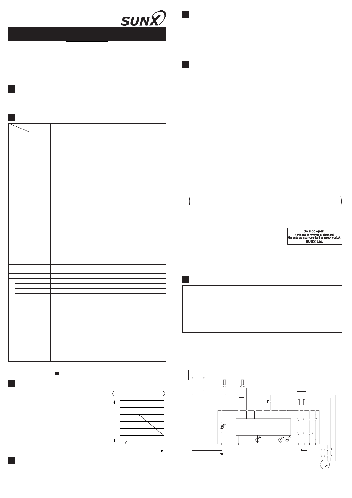
<Wiring for the minus grounding (PNP setting)>
٨ The figure shown below is the case that this product is connected to a type 4
PNP output type light curtain. Connect the control output OSSD 1 and OSSD
2 of the light curtain to S1 and S2 respectively.
Emitter Receiver
Power supply
0V 24V DC
3
INSTALLATION POSITION/DIRECTION/METHOD
٨
Use the 35mm width DIN rail to install the unit.
٨
The installation position/direction is not
basically limited.
Please fix this product with the optional DIN rail
٨
stopper (MS-DIN-E) after installing the product
on to the 35mm width DIN rail.
If two, or more, units are placed side by side,
٨
make sure to space them at least 5mm apart. In
case they are mounted close to each other,
lower the rated operation current of the safety
output depending on the ambient temperature,
refering the right graph.
4
FUNCTIONS
Derating for mounting the
units close to each other
6
5
4
3
2
1
Rated operation current (A)
0
35 40 45 50 55
Ambient temperature ()
ŪTrailing edge switching function
This function is to accept the input when the reset switch is pressed (contact
'close') and then released (contact 'open') at the manual start setting.
An unexpected start-up due to the welded reset switch can be avoided.
+V +V0V
0V
OSSD1
A1
F
Ui
A2 AUX
F.G.
KA, KB: Magnet contactor
OSSD2
RESET
X1 X2 X3S1 S4S2 S3
SF-C13 CONTROL-LOGIC
OUT
INTERLOCK
L1
FUSE 1 FUSE 2
13 23 33 41
K1
K2
FAULT
14 24 34 42
KB
KA
N
M
3
٨ In case of connecting a type 2 PNP output type light curtain, connect the
control output (OSSD) to S1, and also put a jumper between S2 and S3.
<Wiring for the plus grounding (NPN setting)>
٨ The figure shown below is the case that this product is connected to a type 4
NPN output type light curtain. Connect the control output OSSD 1 and OSSD
2 of the light curtain to S4 and S2 respectively.
Emitter Receiver
Power supply
0V 24V DC
8
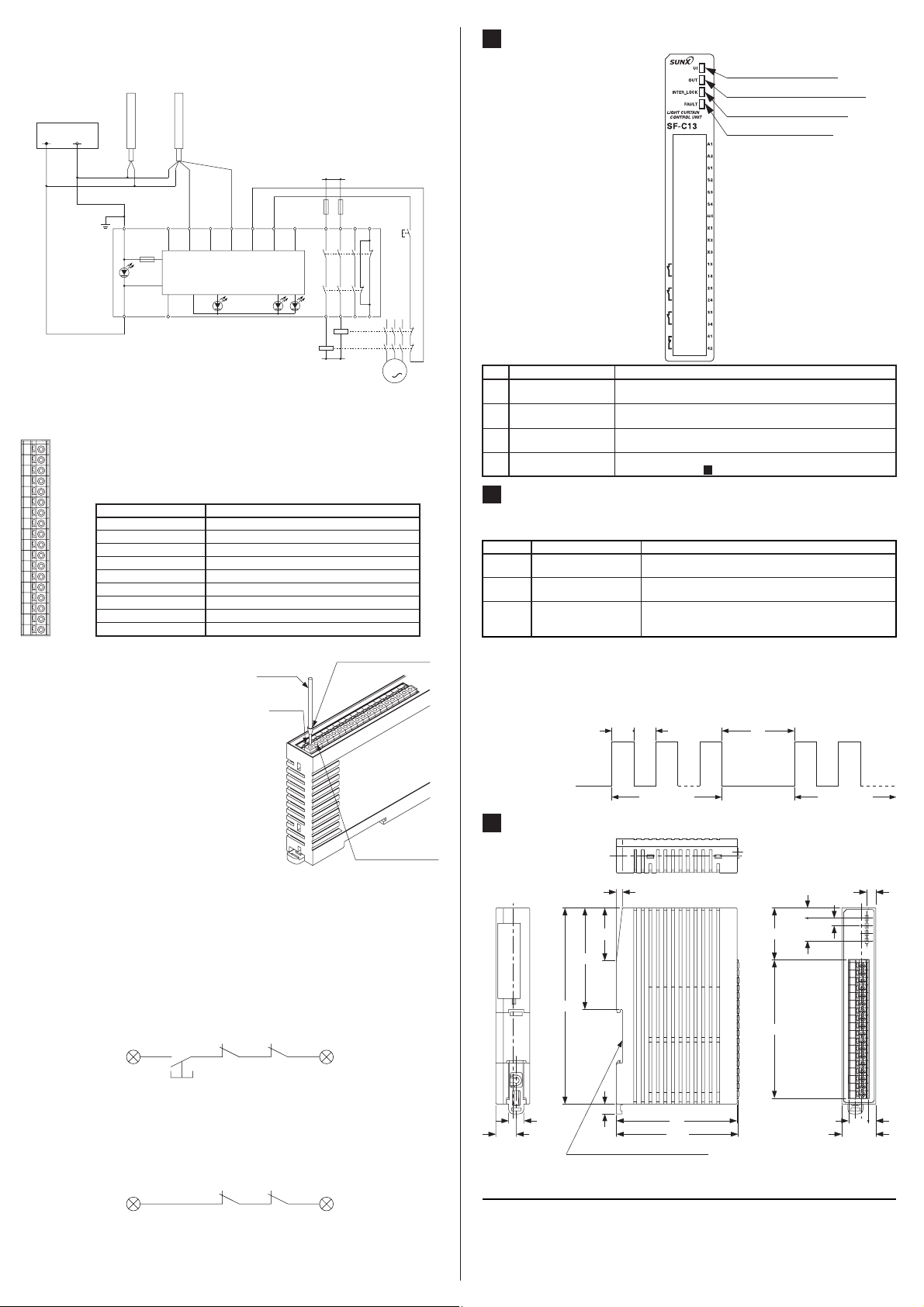
FUNCTIONAL DESCRIPTION
Ԙ Power indicator (Green)
ԙ Safety output indicator (Green)
Ԛ Interlock indicator (Yellow)
ԛ Fault indicator (Yellow)
+V +V0V
0V
OSSD2
A1
F.G.
F
Ui
A2 AUX
KA, KB: Magnet contactor
SF-C13 CONTROL-LOGIC
OUT
OSSD1
X1 X2 X3S1 S4S2 S3
INTERLOCK
L1
FUSE 1 FUSE 2
13 23 33 41
K1
K2
FAULT
14 24 34 42
KB
KA
N
RESET
M
3
٨ In case of connecting a type 2 NPN output type light curtain, connect the
control output (OSSD) to S4, and also put a jumper between S2 and S3.
٨ Terminal arrangement diagram
A1
A2
S1
S2
S3
S4
AUX
X1
X2
X3
13
14
23
24
33
34
41
42
When connecting to the terminal, insert
the solid wire or the twisted wire with a
ferrule (sleeve) terminal as shown in the
figure right (please arrange separately) to
the innermost of the connecting hole.
The wire is locked when it is properly in-
Terminal No. Description
A1
A2
S1 to S4 Light curtain control output (OSSD) input terminal
AUX Semiconductor auxiliary output
X1 Reset output terminal
X2 Reset input terminal (manual)
X3 Reset input terminal (automatic)
13-14, 23-24, 33-34 Safety output (NO contact 3)
41-42 Auxiliary output (NC contact 1)
24V DC
0V
Lead wire
Release
button
Ferrule (sleeve)
terminal
(Please arrange separately)
serted. However, do not to pull the wire
with excessive force, as this can cause a
cable break.
When connecting the twisted wire (lead
wire), without a ferrule (sleeve) terminal,
insert the wire to the innermost of the
connecting hole while pressing the release button.
When releasing the solid wire or the
twisted wire (lead wire), pull the wire
while pressing the release button.
The following solid wire and twisted wire
Solid wire or twisted
wire (lead wire) inlet
(lead wire) are recommended.
Solid wire: Ǿ0.4 to Ǿ1.2mm (AWG 26 to 16)
Twisted wire (lead wire): 0.3 to 1.25mm
2
(AWG 22 to 16)
Standard stripped wire length: 11mm
<Manual reset>
In case of the manual reset, configure the back check circuit between X1 and
X2. If KA and KB aren't needed to check, short-circuit KA and KB.
Do not connect anything to X3.
The control unit operates by the trailing operation of the external reset button.
Two, or more, units cannot be controlled by an external reset button. Prepare
the external reset button for unit by unit.
X1
RESET
KA KB
X2
<Auto reset>
In case of the auto reset, configure the back check circuit between X1 and
X3. If KA and KB aren't needed to check, short-circuit between X1 and X3.
Do not connect anything to X2.
Avoid auto-reset of the system after emergency stop by using the other
control circuit.(IEC/EN 60204-1 part 9.2.5.4.2 and 10.8.3)
X1
KA KB
X3
No.
Ԙ
ԙ
Ԛ
ԛ
9
Description Function
Power indicator
(Ui) (Green)
Safety output indicator
(OUT) (Green)
Interlock indicator
(INTER_LOCK) (Yellow)
Fault indicator
(FAULT) (Yellow)
Lights up when the power is supplied.
Lights up when the safety output is 'close'.
Lights up when the safety output is 'open'.
Blinks when an error occurs.
For details, refer to ' TROUBLESHOOTING'.
TROUBLESHOOTING
9
٨ The number of times the fault indicator (yellow) blinks indicates the type of
error state, as follows.
Blinking Description of error Cause/Measure
2 times
Internal relay contact is weld
3 times Reset mode error
Influence of noise /
4 times
power supply or internal
or more
circuit failure
٨
Make sure that this product and the light curtain a re connected to the
The contact was weld due to the lifetime of the relay.
Replace this product by new one.
Wiring of the terminal X1, X2 or X3 is not correct.
Check if the wiring has been correctly done.
Check the noise environment.
Check the wiring, power supply voltage and voltage
capacity.
common power supply.
٨
When the sensor doesn't operate properly even if the measures described
above are taken, contact our office.
The blinking cycle of the fault indicator (yellow) is as follows. Check the
٨
number of times the indicator blinks after 2 sec. of the indicator 'off' period.
Lights up
Blinking cycle of
fault indicator
Turns off
10
DIMENSIONS (Unit: mm)
67.3
130
10
13.5
Suitable for 35mm width DIN rail
No. of blinks No. of blinks
4
35
6.5
SUNX Limited
80
80.8
2s0.3s 0.3s
6.75
35㧩15
34.5
91.6
http://www.sunx.co.jp/
5
22.5
Head Office
2431-1 Ushiyama-cho, Kasugai-shi, Aichi, 486-0901, Japan
Phone: +81-(0)568-33-7211 FAX: +81-(0)568-33-2631
Overseas Sales Dept.
Phone: +81-(0)568-33-7861 FAX: +81-(0)568-33-8591
PRINTED IN JAPAN
6
513
 Loading...