

Panasonic SF-C12 Installation Manual
ԛ Light curtain input
polarity selection function
㪧㪥㪧
㪥㪧㪥
Ԛ
6.5
㪝㪞
㪘㪉
㪘㪈
㪈㪊
㪈㪋
㪉㪊
㪉㪋
㪊㪈
㪊㪉
㪝㪙㪋
㪝㪙㪊
㪝㪙㪉
㪝㪙㪈
㪩㪄
㪩㪂
㪜㪂
㪜㪄
㪫㪉
㪫㪈
㪯㪉
㪯㪈
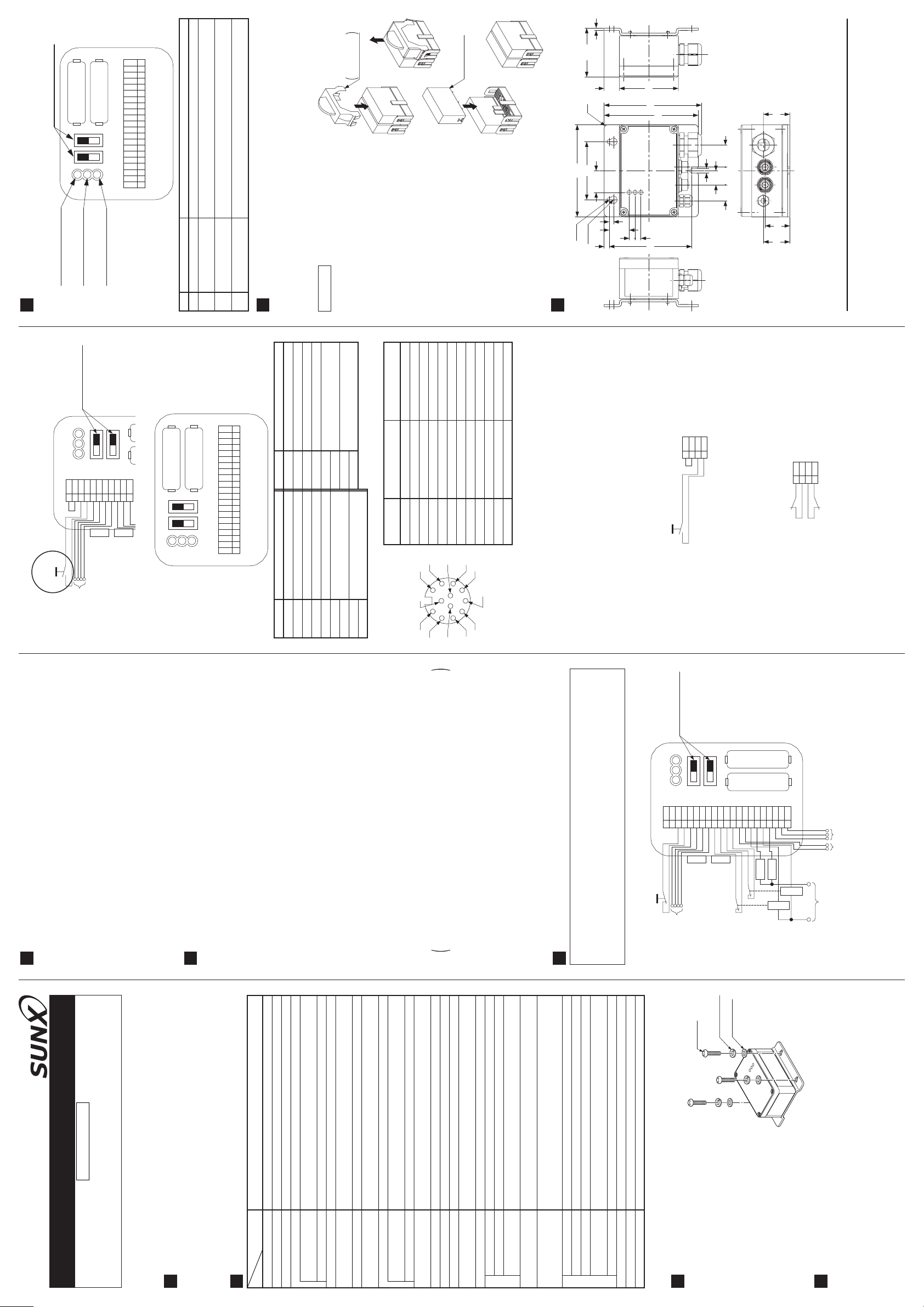
Function
Lights up when the power is supplied.
Lights up when the safety output is 'close'.
Lights up when the setting of the two light curtain input polarity
selection switches is different.
To select either PNP or NPN output of light curtain SF4B series
and plus or minus grounding .
Accessory for
Removing jig
ԙ
SF-C12-RY
Safety relay
(SF-C12-RY)
(optional)
ԛ
67.5
21
R5
80
127
30
6
2-Ǿ6
2-Ǿ10
7
81.4
(135)
130
6
19.5
22 24.5 30.5
28
8
8
114
36.536.5
34.2
http://www.sunx.co.jp/
PRINTED IN JAPAN
(Green)
ԙSafety output indicator
ԘPower indicator (Green)
ԚOperation error indicator
FUNCTIONAL DESCRIPTION
8
Light curtain input po-
larity selection switch
㪧㪥㪧
㪥㪧㪥
㪯㪈㪯㪉㪫㪈㪫㪉㪜㪄㪜㪂㪩㪄
Test input
switch
Emitter side connector
Interference
<Wiring for manual reset setting>
prevention wire
(Orange)
㪩㪂
㪝㪙㪈
㪝㪙㪉
㪝㪙㪊
Receiver side connector
㪧㪥㪧
٨ Terminal arrangement diagram
Description
Power indicator (Green)
Safety output indicator
Ԙ
ԙ
No.
㪥㪧㪥
Operation error indicator
(Green)
Ԛ
Light curtain input
(Orange)
ԛ
㪝㪞
㪘㪉
㪘㪈
㪈㪊
㪈㪋
㪉㪊
㪉㪋
㪊㪈
㪊㪉
㪝㪙㪋
㪝㪙㪊
㪝㪙㪉
㪝㪙㪈
㪩㪂
㪩㪄
㪜㪂
㪜㪄
㪫㪉
㪫㪈
㪯㪉
㪯㪈
polarity selection switch
MAINTENANCE
In case the relay in this product is broken, the safety relay for replacement
(SF-C12-RY) is available.
9
Be sure to replace the two relays at the same time.
٨
٨
Description
Interference prevention wire + (receiver side)
Interference prevention wire - (receiver side)
Interference prevention wire - (emitter side)
R+R-E+E-T2T1X2
Terminal No.
Description
Frame ground terminal
0V
Terminal No.
FG
A2
A1 24V DC
For replacing the safety relays, follow the procedure described below.
Procedure
٨
Interference prevention wire + (emitter side)
Safety output (NO contact 2)
31-32 Auxiliary output (NC contact 1)
13-14, 23-24
Remove the cover of the main body.
Ԙ
Test input terminal
Auto reset / Manual reset selection terminal
External relay monitor terminal 2
FB4
FB3
Fit the removing jig, which is enclosed with
ԙ
short-circuit between X1 and X2
Manual reset:
X1
FB2
the safety relay (SF-C12-RY), into the safe-
External relay monitor terminal 1
FB1
ty relay connected to the main body.
Holding the safety relay in the state the jig
Ԛ
Connector pin
٨ Connector pin position
function so that the pins of the relay bend. Thus, be
pendicularly. (Note)
24V DC
24V DC
ԙ
ԙ
ԡ
Ԙ
sure to fit the safety relay perpendicularly.
Note: Inserting the safety relay slantwise may cause mal-
OSSD 1
EDM (External relay monitor)
Emission halt
Auxiliary output
Ԛ
Ԡ
has been fit, pull out it upwards.
Insert the safety relay for replacement per-
ԛ
OSSD 2
Receiver side connector
Interlock
Emitter side connector
ԘԚԛԜԝԞԟ
No.
DIMENSIONS (Unit: mm)
10
0V
Shield
Synchronization -
Synchronization +
0V
Synchronization -
Synchronization +
Ԣԣ
ԛ
ԟ
Interference prevention wire +
Shield
Interference prevention wire +
ԠԡԢ
Ԝ
ԝ
Ԟ
Muting lamp input 1
Muting lamp input 2
Interference prevention wire -
X1X2T1
T2
FB1
FB2
FB3
Override input
Muting lamp output
Interference prevention wire -
ԣ
type) between T1 and T2. The product operates by trailing operation of the
RESET
reset button.
check circuit to monitor welding of the external contactor as shown in the
When connecting the external contactor KA and KB, configure the back-
<External device monitor>
If it is not necessary to check the external contactor KA and KB, short-circuit
figure below.
the contactor KA and KB.
Note: I/O of the terminal No. Ԣ and ԣ are not used.
Connect a press button switch (NC type) between T1 and T2. The button
<Auto reset>
switch is used for emitting halt.
Do not connect anything between X1 and X2.
Avoid auto-reset of the system after emergency stop by using the other
control circuit.(IEC/EN 60204-1 part 9.2.5.4.2 and 10.8.3)
Connect between X1 to X2. Furthermore, connect a press button switch (NO
<Manual reset>
FB4
KA
SUNX Limited
KB
Head Office
2431-1 Ushiyama-cho, Kasugai-shi, Aichi, 486-0901, Japan
Phone: +81-(0)568-33-7211 FAX: +81-(0)568-33-2631
Overseas Sales Dept.
Phone: +81-(0)568-33-7861 FAX: +81-(0)568-33-8591
FUNCTIONS
Polarity selection function
This is the function to switch either plus grounding or minus grounding with the
polarity selection switch. When the polarity selection switch is set to 'PNP'
side, minus grounding is selected and the connected light curtain SF4B series
is set as PNP output type. When the polarity selection switch is set to 'NPN'
5
Ū
side, plus grounding is selected and the connected light curtain SF4B series is
set as NPN output type.
Since two light curtain input polarity selection switches are equipped, be sure
to set them to the same side.
Trailing edge switching function
This function is to accept the input when the reset switch is pressed (contact
'close') and then released (contact 'open') at the manual start setting.
Ū
CAUTIONS
An unexpected start-up due to the welded reset switch can be avoided.
6
Make sure to carry out the wiring in the power supply off condition.
٨٨٨
Take care that wrong wiring will damage the product.
Verify that the supply voltage variation is within the rating. Take care that if a
voltage exceeding the rated range is applied, or if an AC power supply is di-
rectly connected, the unit may get burnt or damaged.
The DC power supply unit must satisfy the conditions given below:
1) Power supply unit authorized in the region where this device is to be used.
٨
(In case CE conformity is required.)
2) Power supply unit conforming to EMC Directive and Low-voltage Directive
3) Power supply unit conforming to the Low-voltage Directive and with an out-
put of 100VA or less.
a commercially available switching regulator.
The frame ground (F.G.) terminal must be connected to ground when using
4)
5) Power supply unit with an output holding time of 20ms or more.
6) Use an isolation transformer for the DC power supply unit.
7) In case a surge is generated, take countermeasures such as connecting a
surge absorber to the origin of the surge.
Power supply unit corresponding to CLASS 2 (In case C-UL conformity is required.)
8)
<Additional information>
As proved in IEC 60536 (CLASS: Protection against Electric Shook), this
power supply should require no ground earth and satisfy the insulation dis-
tance called double insulation or reinforced insulation.
In case the power supply conforms to Low-voltage Directive and has an
output of 100VA or less, it can be used as a suitable product.
Do not run the wires together with high-voltage lines or power lines or put
them in the same raceway. This can cause malfunction due to induction.
٨
Avoid dust, dirt, and steam.
Take care that the product does not come in direct contact with oil, grease, or
٨
٨
organic solvents, such as, thinner, etc.
Note that this equipment is applicable only in the control circuit grounded in
٨
accordance with IEC 60204-1 and JIS B 9960-1, or in the control circuit in
which the insulation monitor unit (ground fault detection unit) is arranged.
I/O CIRCUIT DIAGRAM
This unit is suitable for indoor use only.
7
٨
When this product is connected to the light curtain, be sure to use the following
connection cable.
SFB-CB05-MU (cable length 0.5m)
SFB-CCJ10E-MU (Extension cable for emitter, cable length 10m)
SFB-CCJ10D-MU (Extension cable for receiver, cable length 10m)
Test input
switch
<Wiring for auto-reset setting>
Light curtain input po-
larity selection switch
㪧㪥㪧
㪥㪧㪥
㪯㪈㪯㪉㪫㪈㪫㪉㪜㪄㪜㪂㪩㪄
Emitter side connector
Interference
prevention wire
M5 screw
㪩㪂
㪝㪙㪈
㪝㪙㪉
Receiver side connector
Spring washer
㪊㪉㪊㪈㪉㪋㪉㪊㪈㪋㪈㪊㪘㪈
㪝㪙㪊
㪝㪙㪋
Plain washer
FUSE
㪘㪉
FUSE
㪝㪞
Power supply input
24V DCr10%
Auxiliary
output
MPCE 2
MPCE 1
Safety output
30V DC / 3A
SF-C12
Sensor Option
Control Unit for SF4B Series
INSTRUCTION MANUAL
Thank you very much for using SUNX products. Please read this Instruction
Manual carefully and thoroughly for the correct and optimum use of this product.
Kindly keep this manual in a convenient place for quick reference.
OUTLINE
European / North American safety standards.
This product in combination with the light curtain SF4B is conforming to up
1
to the control category 4 specified in EN 954-1 (ISO 13849-1/JIS B 9705).
٨ The SF-C12 is a control unit for the light curtain SF4B series conforming to
SF-C12
SF4B series
24V DCr10% Ripple P-P 10% or lessSupply voltage
IEC 61496-1, UL 61496-1, JIS B 9704-1Applicable standard
Model No.
SPECIFICATIONS
Connectable input device
2
Item
NO contact2Safety output
30V DC / 3A, Resistance load (the contact protection for inductive
Rated operation
load), Min. applied load: 15mA or less (CV24V DC)
voltage / current
3A (slow-blow)Fuse
AgNiO+0.2Ǵm Au, Self cleaning, positively driven
Contact material / contacts
Contact resistance
50mǡ or less
(Initial value)
100,000 times or more
10,000,000 times or more (switching frequency 180 times/min.) (Note)Mechanical lifetime
(switching frequency 20 times/min. at rated resistive load) (Note)
Electrical lifetime
Safety relay contact (NC contact)1 (interlocked to safety output)Auxiliary output
30V DC / 3A, Min. applied load: 15mA or less (at 24V DC)
Rated operation
voltage / current
3A (slow-blow)Fuse
Built-in electronic fuse, Breaking current: 0.5A or more, reset by
power supply stop
Fuse (power supply)
AC-15, DC-13 (IEC 60947-5-1)Application category
100mA or less (without light curtain)Current consumption
30ms or less / 30ms or less (Auto reset / Manual reset)Pick-up delay
Response time
14ms or less
(Drop-out delay)
Υ
Green LED (Lights up when power is supplied)Power
Excess voltage category
Green LED (lights up when the safety output is 'close')Safety output
Orange LED (lights up when the setting of the two light curtain input
Incorporated
polarity selection switches is different)
Operation error
Indicators
Trailing edge switching
Incorporated (selectable either plus or minus grounding, selectable with slide switch)
function
Plus grounding: For NPN input type light curtain
Minus grounding: For PNP input type light curtain
Polarity selection function
IP65Protection
35 to 85% RH, Storage: 35 to 85% RHAmbient humidity
-10 to +55(No dew condensation or icing allowed), Storage: -25 to +70
Ambient temperature
10 to 55Hz frequency, 0.75mm amplitude in X, Y and Z directions for
two hours each (in power OFF state)
Vibration resistance
2
European style terminalConnection terminal
Pollution degree
Environmental resistance
2kg approx.Weight
Enclosure: Die-cast aluminumMaterial
environment etc.
INSTALLATION POSITION/DIRECTION/METHOD
Do not use this product in the state where
the protection enclosure is not fitted. Wa-
ter-proof capability can not be maintained.
Tighten connectors securely. Otherwise,
water-proofness can not be maintained.
The installation position/direction is
not basically limited.
The tightening torque for mounting the
main body should be 2N㨯morless.
Furthermore, the control unit should
be fixed at 3 points, as shown in the
3
٨
٨
٨
Note: The lifetime of the switch of relay depends on type of the load, frequency of switching or
٨
right figure.
SHORT-CIRCUIT PROTECTION
The power supply unit of this equipment adopts the electronic fuse which do
not require any replacement.
When the electronic fuse is operated, turn off the power supply, and remove
the cause of overcurrent before restarting the power supply for resetting.
The electronic fuse is not suitable to use in which the equipment is operated
4
٨
continuously or daily. Note that operating the equipment continuously may
٨
٨
not be unable to satisfy the specifications.
 Loading...