

Page 1
INSTRUCTION MANUAL
Light Curtain Type 4 / Heavy-duty / Heavy-dutyHeavy-duty
SF4B-□G<V2>
© Panasonic Electric Works SUNX Co., Ltd. 2010 MJE-SF4BGV2 No.0018-69V
Page 2

(MEMO)
1 © Panasonic Electric Works SUNX Co., Ltd. 2010 MJE-SF4BGV2 No.0018-69V
Page 3

Thank you for purchasing Panasonic Electric Works SUNX’s Light Curtain, SF4B-□G<V2> series.
Please read this instruction manual carefully and thoroughly for the correct and optimum use of
this device.
Kindly keep this manual in a convenient place for quick reference.
This device is a light curtain for protecting a person from dangerous parts of a machine which
can cause injury or accident.
This manual has been written for the following personnel who have undergone suitable training
and have knowledge of light curtains, as well as, safety systems and standards.
who are responsible for the introduction of this device
●
who design the system using this device
●
who install and connect this device
●
who manage and operate a plant using this device
●
Notes
1) All the contents of this instruction manual are the copyright of the publishers, and may
not be reproduced (even extracts) in any form by any electronic or mechanical means
(including photocopying, recording, or information storage and retrieval) without permission in writing from the publisher.
2) The contents of this instruction manual may be changed without prior notice for further
improvement of the device.
3) Though we have carefully drawn up the contents of this instruction manual, if there are
any aspects that are not clear, or any error that you may notice, please contact our local
Panasonic Electric Works SUNX ofce of the nearest distributor.
4) English and Japanese are original instructions.
2© Panasonic Electric Works SUNX Co., Ltd. 2010 MJE-SF4BGV2 No.0018-69V
Page 4

Contens
Chapter 1 Introduction ························································································5
1-1 Attention Marks ····························································································· 5
1-2 Safety Precautions ························································································ 5
1-3 Applicable Standards / Regulations ······························································ 8
1-4 Conrmation of Packed Contents ································································· 9
Chapter 2 Before Using This Device ································································ 10
2-1 Features ······································································································ 10
2-2 Part Description ·························································································· 10
2-3 Protection Area ··························································································· 13
2-3-1 Sensing Area ························································································ 13
2-3-2 Safety Distance ···················································································· 14
2-3-3 Inuence of Reective Surfaces ··························································· 18
2-3-4 Device Placement ················································································· 19
2-4 Mounting ····································································································· 20
2-4-1 Mounting of the Mounting Bracket ························································ 20
2-4-2 Mounting of the Bottom Cap Cable (Optional) ······································ 22
2-4-3 Extension and Dismantling of Sensor (Series Connection) ·················· 23
2-5 Wiring ·········································································································· 25
2-5-1 Power Supply Unit ················································································ 25
2-5-2 I/O Circuit Diagrams and Output Waveform ········································· 26
2-5-3 Wiring · Connecting Procedure and Connector Pin Arrangement ········ 28
2-5-4 Basic Wiring ·························································································· 30
2-5-5 Wiring for Manual Reset (Interlock is Valid) ·········································· 32
2-5-6 Series Connection ················································································ 34
2-5-7 Parallel Connection ·············································································· 36
2-5-8 Series and Parallel Mixed Connection ·················································· 40
2-5-9 Wiring for Auto-reset (Interlock is Invalid) ············································· 45
2-5-10 Wiring Conguration for Invalid External Device Monitor Function ···· 47
2-5-11 Wiring Conguration for Valid Muting Function ··································· 49
2-6 Adjustment ·································································································· 51
2-6-1 Beam-axis Alignment ············································································ 51
2-6-2 Operation Test ······················································································ 53
2-6-3 Operation ······························································································ 54
Chapter 3 Functions ························································································· 61
3-1 Self-diagnosis Function ·············································································· 61
3-2 Interlock Function ······················································································· 61
3-3 Emission Halt Function ··············································································· 62
3-4 Interference Prevention Function ································································ 62
3-5 Auxiliary Output (Non-safety Output) ·························································· 63
3-6 External Device Monitor Function ······························································· 63
3-7 Muting Function ·························································································· 65
3-8 Override Function ······················································································· 68
3-9 Functions Using Handy Controller (SFB-HC) (Optional) ···························· 69
3 © Panasonic Electric Works SUNX Co., Ltd. 2010 MJE-SF4BGV2 No.0018-69V
Page 5

Chapter 4 Maintenance ···················································································· 72
4-1 Daily Inspection ·························································································· 72
4-2 Periodic Inspection (Every Six Months) ······················································ 73
4-3 Inspection after Maintenance ······································································ 73
Chapter 5 Troubleshooting ···············································································74
5-1 Troubleshooting of Emitter ·········································································· 74
5-2 Troubleshooting of Receiver ······································································ 76
Chapter 6 Specications / Dimensions ····························································78
6-1 Specications ······························································································ 78
6-2 Options ······································································································· 83
6-3 Dimensions ································································································· 87
6-3-1
When Mounting on Rear with Standard Ell Mounting Bracket (MS-SF4BG-1)
6-3-2
When Mounting on Side with Standard Ell Mounting Bracket (MS-SF4BG-1)
6-3-5 Mounting Brackets ················································································ 89
·· 87
·· 88
Chapter 7 Others ······························································································90
7-1 Glossary ······································································································ 90
7-2 CE Marking Declaration of Conformity ······················································· 92
4© Panasonic Electric Works SUNX Co., Ltd. 2010 MJE-SF4BGV2 No.0018-69V
Page 6
Chapter 1 Introduction
1-1 Attention Marks
This instruction manual employs the following attentions marks
the degree of the danger to call operator’s attention to each particular action. Read the following
explanation of these marks thoroughly and observe these notices without fail.
If you ignore the advice with this mark, death or serious injury could result.
If you ignore the advice with this mark, injury or material damage could result.
<Reference>
It gives useful information for better use of this device.
,
depending on
1-2 Safety Precautions
Use this device as per its specications. Do not modify this device since its functions and ca-
■
pabilities may not be maintained and it may malfunction.
This device has been developed / produced for industrial use only.
■
This device is suitable for indoor use only.
■
Use of this device under the following conditions or environments is not presupposed. Please
■
consult us if there is no other choice but to use this device in such an environment.
1) Operating this device under conditions or environments not described in this manual.
2) Using this device in the following elds: nuclear power control, railroad, aircraft, auto
mobiles, combustion facilities, medical systems, aerospace development, etc.
When this device is to be used for enforcing protection of a person from any danger oc-
■
curring around an operating machine, the user should satisfy the regulations established by
national or regional security committees (Occupational Safety and Health Administration:
OSHA, the European Standardization Committee, etc.). Contact the relative organization(s)
for details.
In case of installing this device to a particular machine, follow the safety regulations in regard
■
to appropriate usage, mounting (installation), operation and maintenance. The users including the installation operator are responsible for the introduction of this device.
Use this device by installing suitable protection equipment as a countermeasure for failure,
■
damage, or malfunction of this device.
Before using this device, check whether the device performs properly with the functions and
■
capabilities as per the design specications.
In case of disposal, dispose this device as an industrial waste.
■
5 © Panasonic Electric Works SUNX Co., Ltd. 2010 MJE-SF4BGV2 No.0018-69V
Page 7

Machine designer, installer, employer and operator
♦
The machine designer, installer, employer and operator are solely responsible to en-
●
sure that all applicable legal requirements relating to the installation and the use in any
application are satised and all instructions for installation and maintenance contained in
the instruction manual are followed.
Whether this device functions as intended to and systems including this device comply
●
with safety regulations depends on the appropriateness of the application, installation,
maintenance and operation. The machine designer, installer, employer and operator are
solely responsible for these items.
Engineer
♦
The engineer would be a person who is appropriately educated, has widespread knowl-
●
edge and experience, and can solve various problems which may arise during work,
such as a machine designer, or a person in charge of installation or operation etc.
Operator
♦
The operator should read this instruction manual thoroughly, understand its contents,
●
and perform operations following the procedures described in this manual for the correct operation of this device.
In case this device does not perform properly, the operator should report this to the per-
●
son in charge and stop the machine operation immediately. The machine must not be
operated until correct performance of this device has been conrmed.
Environment
♦
Do not use a mobile phone or a radio phone near this device.
●
If there exists a reective surface in the place where this device is to be installed, make
●
sure to install this device so that reected light from the reective surface does not enter
into the receiver, or take countermeasures such as painting, masking, roughening, or
changing the material of the reective surface, etc. Failure to do so may cause the device not to detect, resulting in death or serious injury.
Do not install this device in the following environments.
●
1) Areas exposed to intense interference (extraneous) light such as high-frequency uo-
rescent lamp (inverter type), rapid starter uorescent lamp, stroboscopic lights or direct
sunlight.
2) Areas with high humidity where condensation is likely to occur
3) Areas exposed to corrosive or explosive gases
4) Areas exposed to vibration or shock of levels higher than that specied
5) Areas exposed to contact with water
6) Areas exposed to too much steam or dust
Installation
♦
Always keep the correctly calculated safety distance between this device and the dan-
●
gerous parts of the machine.
Install extra protection structure around the machine so that the operator must pass
●
through the sensing area of this device to reach the dangerous parts of the machine.
Install this device such that some part of the operator ’s body always remains in the
●
sensing area when operator is done with the dangerous parts of the machine.
Do not install this device at a location where it can be affected by wall reection.
●
When installing multiple sets of this device, connect the sets and, if necessary, install
●
some barriers such that mutual interference does not occur. For details, refer to “2-3-4
Device Placement” and “3-4 Interference Prevention Function.”
Do not use this device in a reective conguration.
●
The corresponding emitter and receiver must have the same serial No. and be correctly
●
oriented.
6© Panasonic Electric Works SUNX Co., Ltd. 2010 MJE-SF4BGV2 No.0018-69V
Page 8

Machine in which this device is installed
♦
When this device is used in the “PSDI Mode,” an appropriate control circuit must be con-
●
gured between this device and the machinery. For details, be sure to refer to the stan-
dards or regulations applicable in each region or country.
In Japan and Korea, do not use this device as safety equipment for a press machine.
●
Do not install this device with a machine whose operation cannot be stopped immedi-
●
ately in the middle of an operation cycle by an emergency stop equipment.
This device starts the performance after 2 seconds from the power ON. Have the control
●
system started to function with this timing.
Wiring
♦
Be sure to carry out the wiring in the power supply OFF condition.
●
All electrical wiring should conform to the regional electrical regulations and laws. The
●
wiring should be done by engineer(s) having the special electrical knowledge.
Do not run the wires together with high-voltage lines or power lines or put them in the
●
same raceway. This can cause malfunction due to induction.
In case of extending the cable of the emitter or the receiver, each can be extended up
●
to 50m by using the exclusive cable. Furthermore, if the cable is extended in the state
that the device is in series connection, or the muting lamp is used, the total extendable
length of the cable depends on the number of the devices in series connection. For
details, refer to “2-5-3 Wiring · Connecting Procedure and Connector Pin Arrange-
ment.”
Do not control the device only at one control output (OSSD 1 / 2).
●
In order that the output is not turned to ON due to earth fault of the control output (OSSD
●
1 / 2) wires, be sure to ground to 0V side (PNP output) / +24V side (NPN output).
Maintenance
♦
When replacement parts are required, always use only genuine supplied replacement
●
parts. If substitute parts from another manufacturer are used, the device may not come
to detect, result in death or serious injury.
The periodical inspection of this device must be performed by an engineer having the
●
special knowledge.
After maintenance or adjustment, and before starting operation, test this device fol-
●
lowing the procedure specied in “Chapter 4 Maintenance.”
Clean this device with a clean cloth. Do not use any volatile chemicals.
●
Others
♦
Never modify this device. Modication may cause the device not to detect, resulting in
●
death or serious injury.
Do not use this device to detect objects ying over the sensing area.
●
Do not use this device to detect transparent objects, translucent objects or objects
●
smaller than the specied minimum sensing objects.
7 © Panasonic Electric Works SUNX Co., Ltd. 2010 MJE-SF4BGV2 No.0018-69V
Page 9
1-3 Applicable Standards / Regulations
This device complies with the following standards / regulations.
<EU Directives>
EU Machinery Directive 2006/42/EC
EMC Directive 2004/108/EC
<European Standards>
EN 61496-1 (Type 4), EN 55011, EN 61000-6-2, EN 50178
EN ISO 13849-1: 2008 (Category 4, PLe)
<International Standards>
IEC 61496-1/2 (Type 4), ISO 13849-1: 2006 (Category 4, PLe), IEC 61508-1~7 (SIL3)
<Japanese Industrial Standards (JIS)>
JIS B 9704-1/2 (Type 4), JIS B 9705-1 (Category 4), JIS C 0508 (SIL3)
<Standards in US / Canada>
ANSI/UL 61496-1/2 (Type 4), ANSI/UL 508, UL 1998 (Class 2)
CAN/CSA C22.2 No.14, CAN/CSA C22.2 No.0.8
<Regulations in US>
OSHA 1910.212, OSHA 1910.217(C), ANSI B11.1 to B11.19, ANSI/RIA 15.06
Regarding EU Machinery Directive, a Notied Body, TUV SUD, has certied with the type examination certicate.
With regard to the standards in US / Canada, a NRTL, UL (Underwriters Laboratories Inc.) has
certied for C-UL US Listing Mark.
<Reference>
The conformity to JIS, OSHA and ANSI for this device has been evaluated by ourselves.
The C-UL US Listing Mark indicates compliance with both Canadian and US requirements.
This device conforms to the EMC Directive and the Machinery Directive. The mark on the main body
indicates that this device conforms to the EMC Directive.
In Japan, never use this device as a safety equipment for any press machine or
●
shearing machine.
When this device is used in a place other than the places shown above, be sure
●
to conrm the standards or regulations applicable in each region or country be-
fore use
8© Panasonic Electric Works SUNX Co., Ltd. 2010 MJE-SF4BGV2 No.0018-69V
Page 10

1-4 Conrmation of Packed Contents
Sensor: Emitter, Receiver 1 pc. each
□
□
Test Rod 1 pc.
SF4B-F□G<V2>: SF4B-TR14 (ø14 × 220mm)
SF4B-H□G<V2>: SF4B-TR25 (ø25 × 220mm)
Intermediate Supporting Bracket (MS-SF4BG-2) 0 to 3 sets
□
Note: The intermediate support bracket (MS-SF4BG-2) is enclosed with the following devices. The quantity differs
depending on the device as shown below:
1 set: SF4B-F□G<V2> … 79 to 127 beam channels
SF4B-H□G<V2> … 40 to 64 beam channels
SF4B-A□G<V2> … 20 to 32 beam channels
2 sets: SF4B-H□G<V2> … 72 to 96 beam channels
SF4B-A□G<V2> … 36 to 48 beam channels
Instruction Manual (this manual) 1 pc.
□
9 © Panasonic Electric Works SUNX Co., Ltd. 2010 MJE-SF4BGV2 No.0018-69V
Page 11
Chapter 2 Before Using This Device
2-1 Features
This device is the light curtain with the following features.
No special controller is required.
●
The control output (OSSD 1 / 2) is PNP / NPN output switching type.
●
Beam-axis alignment indicators which make beam-axis alignment easy are incorporated.
●
Each function setting is available by using the handy controller (SFB-HC) (optional). Refer to
●
“3-9 Functions Using Handy Controller (SFB-HC) (Optional)” for details.
Refer to “6-2 Options” for details of options.
●
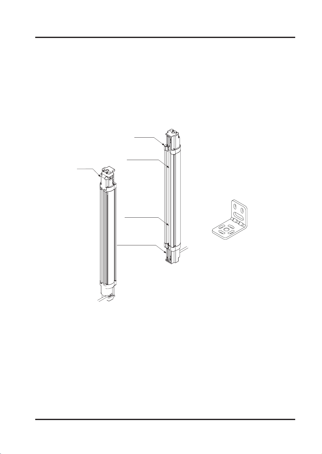
2-2 Part Description
Receiver
Beam channel
Emitter
<Standard ell mounting bracket (Optional)>
Display section
Bottom cap cable
(Optional)
10© Panasonic Electric Works SUNX Co., Ltd. 2010 MJE-SF4BGV2 No.0018-69V
Page 12

<Emitter>
It emits light to the receiver facing it. Furthermore, the status of the emitter and the receiver is
indicated on its display section.
<Receiver>
It receives light from the emitter facing it. Simultaneously, it turns ON the control output (OSSD
1 / 2) when the all beam channels receive light from emitter, and it turns OFF the control output
(OSSD 1 / 2) when one or more beam channels are blocked light.
[Exclude when using the muting function (Note 1) or the blanking function (Note 2).]
Besides, the receiver displays its status on the display section.
Notes: 1)
SFB-CCB□-MU) (optional), muting sensor and muting lamp are required. Please purchase 12-core bot-
2) The blanking function is set by using the handy controller (SFB-HC) (optional). Please purchase the
In case of using the muting function, the following items, 12-core bottom cap cable (SFB-CB05-MU,
tom cap cable, muting sensor, and muting lamp separately.
handy controller separately.
<Beam channel>
The light emitting elements of the emitter and the light receiving elements of the receiver are
placed at the following intervals, 10mm (SF4B-F□G<V2>), 20mm (SF4B-H□G<V2>), and 40mm
(SF4B-A□G<V2>).
<Sensor mounting bracket (optional)>
This bracket is to be used when mounting the emitter or the receiver on back or side.
<Intermediate supporting bracket>
This bracket is to be used for mounting the device having 79 beam channels or more for
SF4B-F□G<V2>, 40 beam channels or more for SF4B-H□G<V2>, 20 beam channels or more
for SF4B-A□G<V2>.
11 © Panasonic Electric Works SUNX Co., Ltd. 2010 MJE-SF4BGV2 No.0018-69V
Page 13
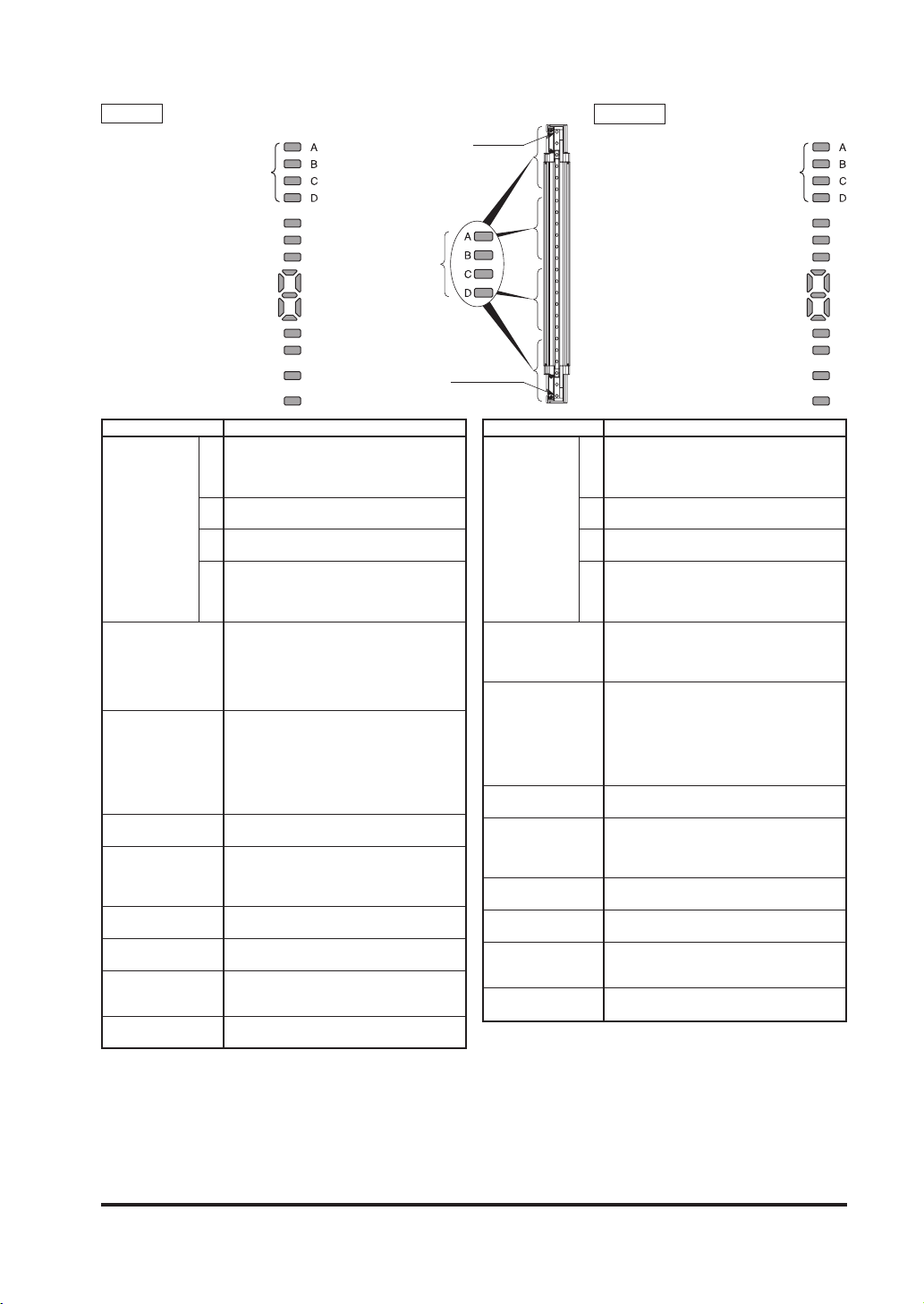
<Display section>
Emitter
Beam-axis alignment indicator
[RECEPTION]
Receiver
Top end
Beam-axis alignment indicator
[RECEPTION]
Operation indicator [OSSD]
Incident light intensity indicator [STB.]
Fault indicator [FAULT]
Beam-axis
alignment
OSSD indicator [OSSD]
Incident light intensity indicator [STB.]
Fault indicator [FAULT]
indicator
Digital error indicator
PNP indicator [PNP]
NPN indicator[NPN]
Emission intensity control indicator
[CTRL]
Emission halt indicator [HALT]
Description Function
Beam-axis
alignment indicator
(Red / Green)
[RECEPTION]
Operator indicator
(Red / Green) [OSSD]
(Note 1)
Incident light intensity
indicator
(Orange / Green)
[STB.]
Fault indicator (Yellow)
[FAULT]
Digital error indicator
(Red)
PNP indicator (Orange)
[PNP]
NPN indicator (Orange)
[NPN]
Em is si on inten si ty
control indicator
(Orange) [CTRL]
Emission halt indicator
(Orange) [HALT]
When device top receives light: lights up in red
When device top end receives light: blinks in red
A
When control output (OSSD 1 / 2) is ON:
When device upper middle receives light: lights up in red
B
When control output (OSSD 1 / 2) is ON: lights up in green
When device lower middle receives light: lights up in red
C
When control output (OSSD 1 / 2) is ON: lights up in green
When device bottom receives light: lights up in red
When device bottom end receives light: blinks in red
D
When control output (OSSD 1 / 2) is ON:
Lights up while device operation is as follows
[sequential operation control output (OSSD1 / 2)]
When control output (OSSD 1 / 2) is OFF:
When control output (OSSD 1 / 2) is ON:
When sufcient light is received
(Incident light: 130% or more) (Note 2): lights up in green
When stable light is received
(Incident light: 115 to 130%) (Note 2): OFF
When unstable light is received
(Incident light : 100 to 115%) (Note 2): lights up in orange
When light is blocked: OFF (Note 3)
When fault occurs in the device:
When device is lockout, error contents are indicated.
When the sensors are connected in parallel, the bottom of the digital error indicator
on the slave side sensors lights up in red.
When PNP output is set: lights up
When NPN output is set: lights up
When light is emitted under short mode:
When light is emitted under normal mode: OFF
When light emission is halt: lights up
When light is emitted: OFF
[RECEPTION]
lights up in green
lights up in green
lights up in red
lights up in green
lights up or blinks
lights up
Bottom end
Description Function
Beam-axis
alignment indicator
(Red / Green)
[RECEPTION]
OSSD indicator
(Red / Green) [OSSD]
Incident light intensity
indicator
(Orange / Green)
[STB.]
Fault indicator (Yellow)
[FAULT]
Digital error indicator
(Red)
PNP ind ic a t or (O r ange )
[PNP]
NPN indicator (Orange)
[NPN]
Function setting indicator
(orange) [FUNCTION]
Interlock indicator
(Yellow) [INTERLOCK]
Digital error indicator
PNP indicator [PNP]
NPN indicator [NPN]
Function setting indicator
[FUNCTION]
Interlock indicator [INTERLOCK]
When device top receives light: lights up in red
When device top end receives light: blinks in red
A
When control output (OSSD 1 / 2) is ON:
When device upper middle receives light: lights up in red
B
When control output (OSSD 1 / 2) is ON: light up in green
When device lower middle receives light: lights up in red
C
When control output (OSSD 1 / 2) is ON: lights up in green
When device bottom receives light: lights up in red
When device bottom end receives light: blinks in red
D
When control output (OSSD 1 / 2) is ON:
When control output (OSSD 1 / 2) is OFF:
When control output (OSSD 1 / 2) is ON:
When sufcient light is received
(Incident light: 130% or more) (Note 2): lights up in green
When stable light is received
(Incident light: 115 to 130%) (Note 2): OFF
When unstable light is received
(Incident light : 100 to 115%) (Note 2): lights up in orange
When light is blocked: OFF (Note 3)
When fault occurs in the device:
When device is lockout, error contents are indicated.
When the sensors are connected in parallel, the bottom of the digital error indicator
on the slave side sensors lights up in red.
When PNP output is set: light up
When NPN output is set: lights up
When blanking function is used:
When connecting the handy controller: brinks
When device is interlocked: lights up
lights up in green
lights up in green
lights up in red
lights up in green
light up or blinks
lights up (Note 4)
Other cases: OFF
Notes: 1) Since the color of the operation indicator changes according to ON / OFF status of the control output
(OSSD 1 / 2), the operation indicator is marked as “OSSD” on the device.
2) The threshold where the control output (OSSD 1 / 2) changes from OFF to ON is applied as “100%
incident light intensity”.
3) “When light is blocked” refers to the status that there exists any object blocking light in the sensing area.
4) The blanking function is set by using the handy controller (SFB-HC) (optional). Please purchase the handy
controller separately.
5) The description given in [ ] is marked on the device.
12© Panasonic Electric Works SUNX Co., Ltd. 2010 MJE-SF4BGV2 No.0018-69V
Page 14
2-3 Protection Area
2-3-1 Sensing Area
Be sure to install protection structure around the machine so that the operator
●
must pass through the sensing area of this device to reach the dangerous parts
of the machine. Furthermore, ensure that some part of the operator’s body always remains in the sensing area when operation is done with the dangerous
parts of the machine. Failure to do so can result in death or serious injury.
Do not use any reection type or recursive reection type arrangement.
●
Furthermore, facing several receivers towards one emitter, or vice versa, could
●
produce a non-sensing area or cause mutual interference, which may result in
death or serious injury.
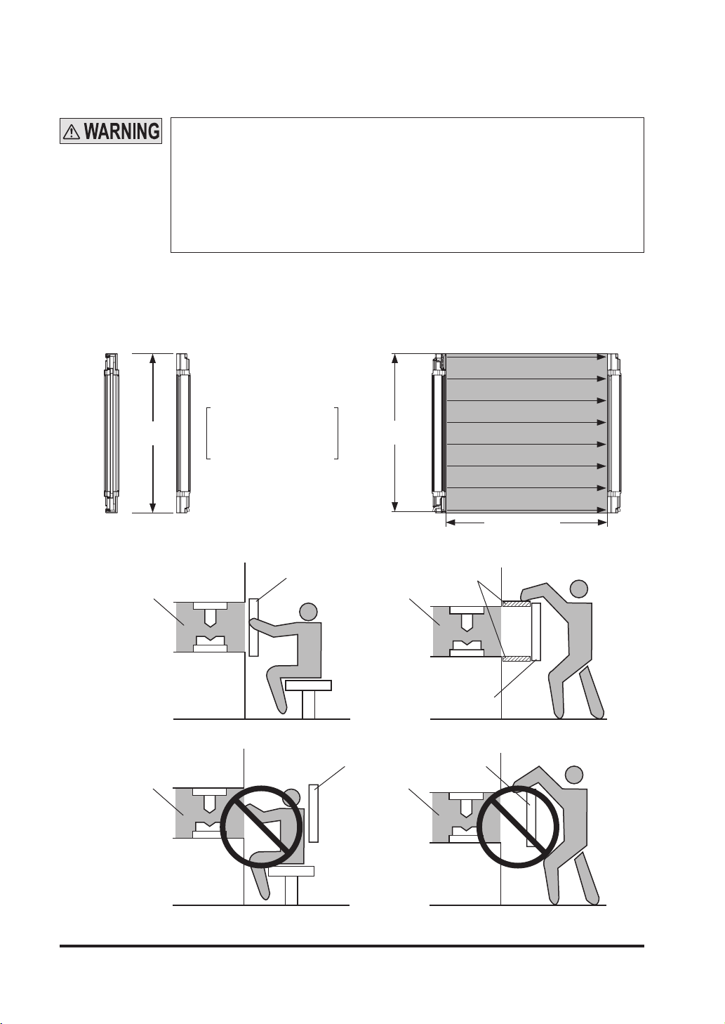
The sensing area is the zone formed by the sensing height of the device and the sensing range
between the emitter and the receiver. The sensing height is determined by the number of beam
channels. Furthermore, the sensing range can be 0.3 to 9m for SF4B-H□G<V2> (12 to 64 beam
channels) and SF4B-A□G<V2> (6 to 32 beam channels), 0.3 to 7m for SF4B-F□G<V2> and
SF4B-H□G<V2> (72 to 96 beam channels) and SF4B-A□G<V2> (36 to 48 beam channels).
Top
Emitter Receiver
Sensing
height
Bottom
The s en si ng height is the
area between the line indicated in the top part and line
indicated in the bottom part.
<Example of Correct Installation>
Dangerous
part
<Example of Incorrect Installation>
Dangerous
part
Sensing
area
Sensing
height
Protective structure
Dangerous
part
Sensing
area
Dangerous
part
Sensing area
Sensing range
Sensing
area
Sensing
area
13 © Panasonic Electric Works SUNX Co., Ltd. 2010 MJE-SF4BGV2 No.0018-69V
Page 15
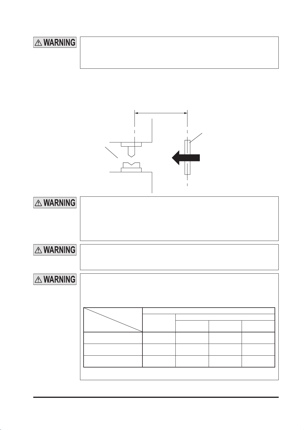
2-3-2 Safety Distance
Calculate the safety distance correctly, and always maintain the distance which
is equal to or greater than the safety distance, between the sensing area of this
device and the dangerous parts of the machine. If the safety distance is miscal-
culated or if sufcient distance is not maintained, the machine will not stop quickly
before reaching to the dangerous parts, which can result in death or serious injury.
The safety distance is the minimum distance that must be maintained between the device and
the dangerous parts of the machine so that the machine can be stopped before a human body
or an object can reach the dangerous parts.
The safety distance is calculated based on the equation described in the next page when a person moves perpendicular (normal intrusion) to the sensing area of the device.
Safety distance S
Sensing area
Dangerous
part
Intrusion direction
Before designing the system, refer to the relevant standards of the region where
this device is to be used, and then install this device.
Furthermore, the equation described in the next pages is to be used only in case
the intrusion direction is perpendicular to the sensing area. In case the intrusion
direction is not perpendicular to the sensing area, be sure to refer to the relevant
standard (regional standard, specication of the machine, etc.) for details of the
calculation.
The max. response time of the machine is from the point that the machine receives the halt signal from this device to the point that the dangerous parts of the
machine stops. The max. response time of the machine should be timed with the
machine to be actually used.
The size of the minimum sensing object for this device varies depending on the
case whether the oating blanking function is applied or not. Calculate the safety
distance with the proper size of the minimum sensing object and appropriate
equation.
<Size of minimum sensing object when applying oating blanking function>
Floating blanking function
Invalid
SF4B-F□G<V2>
(10mm-beam channel pitch type)
SF4B-H□G<V2>
(20mm-beam channel pitch type)
SF4B-A□G<V2>
(40mm-beam channel pitch type)
Note: Refer to “3-9 Functions Using Handy Controller (SFB-HC) (Optional)” for details of
the oating blanking function.
ø14mm ø24mm ø34mm ø44mm
ø25mm ø45mm ø65mm ø85mm
ø45mm ø85mm ø125mm ø165mm
1 beam
channel
Setting (Note)
2 beam
channels
3 beam
channels
14© Panasonic Electric Works SUNX Co., Ltd. 2010 MJE-SF4BGV2 No.0018-69V
Page 16

[For use in Europe (EU) (as EN 999)] (Also applicable to ISO 13855)
(For intrusion direction perpendicular to the sensing area)
<In case that the minimum sensing object is ø40mm or less>
Equation 1 S = K × T + C
●
S : Safety distance (mm)
Minimum required distance between the sensing area surface and the danger-
ous parts of the machine
K : Intrusion velocity of operator’s body or object (mm/sec.)
Taken as 2,000 (mm/sec.) for calculation
T : Response time of total equipment (sec.)
T = Tm + T
SF4B
Tm: Maximum halting time of machine (sec.)
T
SF4B
: Response time of this device (sec.)
C : Additional distance calculated from the size of the minimum sensing object of
the device (mm)
However, the value of C cannot be under 0.
C = 8 × (d - 14)
d: Minimum sensing object diameter (mm)
<Reference>
For calculating the safety distance S, there are the following ve cases.
●
First calculate by substituting the value K = 2,000 (mm/sec.) in the equation above. Then, classify the ob-
tained value of S into three cases, 1) S < 100, 2) 100 ≤ S ≤ 500, and 3) S > 500.
For Case 3) S > 500, recalculate by substituting the value K = 1,600 (mm/sec.). After that, classify the
calculation result into two cases, 4) S ≤ 500 and 5) S > 500. For details, refer to “Calculation Example 1
For use in Europe.”
When this device is used in the “PSDI Mode,” an appropriate safety distance S must be calculated. For
●
details, be sure to refer to the standards or regulations applicable in each region or country.
<In case that the minimum sensing object is over ø40mm>
Equation S = K × T + C
●
S : Safety distance (mm)
Minimum required distance between the sensing area surface and the danger-
ous parts of the machine
K : Intrusion velocity of operator’s body or object (mm/sec.)
Taken as 1,600 (mm/sec.) for calculation
T : Response time of total equipment (sec.)
T = Tm + T
SF4B
Tm: Maximum halting time of machine (sec.)
SF4B
T
: Response time of this device (sec.)
C : Additional distance calculated from the size of the minimum sensing object of
the device (mm)
C = 850 (mm)
15 © Panasonic Electric Works SUNX Co., Ltd. 2010 MJE-SF4BGV2 No.0018-69V
Page 17

<Calculation Example>
●
Calculation Example 1: For use in Europe
(OFF response time: 14ms or less, minimum sensing object diameter: 14mm)
First, calculate with K = 2,000.
S = K × T + C
= K × (Tm + T
SF4B
) + 8 × (d - 14)
= 2,000 × (Tm + 0.014) + 8 × (14 - 14)
= 2,000 × Tm + 2,000 × 0.014
= 2,000 × Tm + 28
If the result is:
1) In case S < 100 (mm)
Safety distance S is taken as 100 (mm)
2) In case 100 ≤ S ≤ 500 (mm)
Safety distance S is taken as 2,000 × Tm + 28 (mm)
3) In case S > 500 (mm)
SF4B
S = K’ × (Tm + T
) + 8 × (d - 14)
= 1,600 × (Tm + 0.014) + 8 × (14 - 14)
= 1,600 × Tm + 1,600 × 0.014
= 1,600 × Tm + 22.4
then, calculate again.
If the result is:
4) In case S ≤ 500 (mm)
Safety distance S is taken as 500 (mm)
5) In case S > 500 (mm)
Safety distance S is taken as 1,600 × Tm + 22.4 (mm)
In case this device is installed in a system with a maximum halting time of 0.1 (sec.)
S = 2,000 × Tm + 28
= 2,000 × 0.1 + 28
= 228
Since this value matches with Case 2) above, S is 228 (mm).
In case this device is installed in a system with a maximum halting time of 0.4 (sec.)
S = 2,000 × Tm + 28
= 2,000 × 0.4 + 28
= 828
Since this value matches with Case 3) above,
S = 1,600 × Tm + 22.4
= 1,600 × 0.4 + 22.4
= 662.4
Since this value matches with Case 5) above, S is 662.4 (mm).
16© Panasonic Electric Works SUNX Co., Ltd. 2010 MJE-SF4BGV2 No.0018-69V
Page 18

[For use in the United States of America (as per ANSI B11.19)]
Equation 2 Ds = K × (Ts + Tc + T
●
: Safety distance (mm)
Ds
SF4B
+ Tbm) + D
pf
Minimum required distance between the sensing area surface and the danger-
ous parts of the machine
K :
Intrusion speed {Recommended value in OSHA is 63 (inch/sec.) [≈ 1,600 (mm/sec.)] }
ANSI B11.19 does not dene the intrusion speed “K”. When determining K, con-
sider possible factors including physical ability of operators.
Ts :
Tc :
T
Halting time calculated from the operation time of the control element (air valve, etc.) (sec.)
Maximum response time of the control circuit required for functioning the brake (sec.)
: Response time of this device (sec.)
SF4B
Tbm : Additional halting time tolerance for the brake monitor (sec.)
The following equation holds when the machine is equipped with a brake monitor.
Tbm = Ta - (Ts + Tc)
Ta: Setting time of brake monitor (sec.)
When the machine is not equipped with a brake monitor, it is recommended that
20% or more of (Ts + Tc) is taken as additional halting time.
pf
: Additional distance calculated from the size of the minimum sensing object of
D
the device (mm)
SF4B-F□G<V2> Dpf = 23.8mm
SF4B-H□G<V2>
SF4B-A□G<V2>
Dpf = 61.2mm
Dpf = 129.2mm
Dpf = 3.4 × (d - 0.276) (inch)
≈ 3.4 × (d - 7) (mm)
d: Minimum sensing object diameter 0.552 (inch) ≈ 14 (mm) SF4B-F□G<V2>
Minimum sensing object diameter 0.985 (inch) ≈ 25 (mm) SF4B-H□G<V2>
Minimum sensing object diameter 1.772 (inch) ≈ 45 (mm) SF4B-A□G<V2>
<Reference>
When the oating blanking function is applied, the minimum sensing object becomes large. According to
ANSI B11.1, Dpf = 900mm (3ft) when d > 64mm (2.5 inches).
<Reference>
Since the calculation above is performed by taking 1 (inch) = 25.4 (mm), there is a slight difference between the representation in (mm) and that in (inch). Refer to the relevant standard for the details.
<Calculation Example>
Calculation Example 2 For use in the United States of America
●
[OFF response time: 14ms or less, minimum sensing object diameter: 0.552 (inch) ≈ 14 (mm)]
= K × (Ts + Tc + T
Ds
SF4B
+
bm
T
) + D
pf
= 63 × (Ta + 0.014) + 3.4 × (d - 0.276) (inch)
= 63 × (Ta + 0.014) + 3.4 × (0.552 - 0.276)
= 63 × Ta + 63 x 0.014 + 3.4 × 0.276
= 63 × Ta + 1.8204
≈ 63 × Ta + 1.82 (inch)
In case this device is installed in a system with a maximum halting time 0.1 (sec.)
Ds = 63 × Ta + 1.82
= 63 × 0.1 + 1.82
= 8.12 (inch)
≈ 206.248 (mm)
Hence, as per the calculations Ds is 206.2 (mm).
<Reference>
Since the calculation above is performed by taking 1 (inch) = 25.4 (mm), there is a slight difference between the representation in (mm) and that in (inch). Refer to the relevant standard for the details.
17 © Panasonic Electric Works SUNX Co., Ltd. 2010 MJE-SF4BGV2 No.0018-69V
Page 19
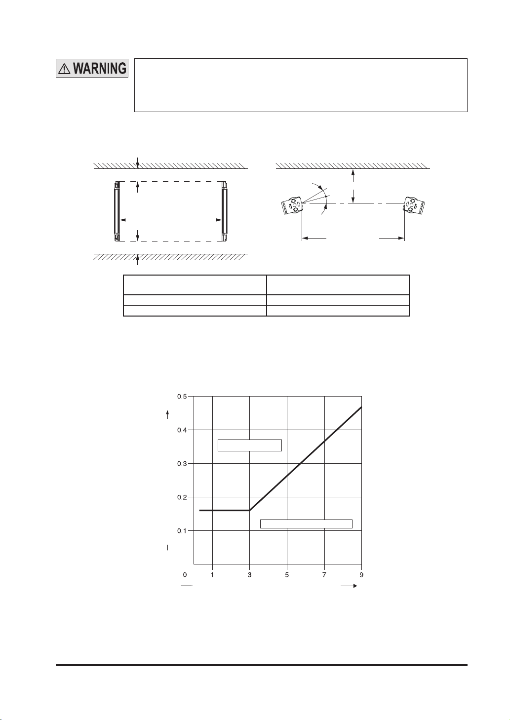
2-3-3 Inuence of Reective Surfaces
If there exists a reective surface in the place where this device is to be installed,
make sure to install this device so that reected light from the reective surface
does not enter into the receiver, or take countermeasures such as painting, mask-
ing, roughening, or changing the material of the reective surface, etc. Failure to
do so may cause the device not to detect, resulting in death or serious injury.
Install this device at a distance of at least A (m) (given below) away from reective surfaces such as metal walls, oors, ceilings, workpieces, covers, panels or glass surfaces.
<Side View>
Reective ceiling
<Top View>
Reective surface
Emitter Receiver
Notes: 1)
2) The effective aperture angle for this device is ±2.5° or less (when L > 3m) as required by IEC
A
A
Emitter Receiver
Sensing range
L
A
Reective oor
Distance between emitter and receiver
(Sensing range L)
0.3 to 3m 0.16m
3 to 9m (Note 1) L/2 × tan 2θ = L/2 × 0.105 (m) (θ = 3°)
The sensing range L is applicable to SF4B-H□G<V2> (12 to 64 beam channels) and SF4B-A□G<V2>
(6 to 32 beam channels). For SF4B-F□<V2> and SF4B-H□<V2> (72 to 96 beam channels) and
SF4B-A□G<V2> (36 to 48 beam channels), the distance between emitter and receiver is 3 to 7m.
61496-2, ANSI/UL 61496-2. However, install this device away from reective surfaces considering
an effective aperture angle of ±3° to take care of beam misalignment, etc. during installation.
Allowable installation distance A
θ
θ
Sensing range
L
Allowable Distance from This Device to Reective Surface
Install in this area
Do not install in this area
Allowable installation distance A (m) installation distance A (m)
Distance between emitter and receiver L (m)
18© Panasonic Electric Works SUNX Co., Ltd. 2010 MJE-SF4BGV2 No.0018-69V
Page 20
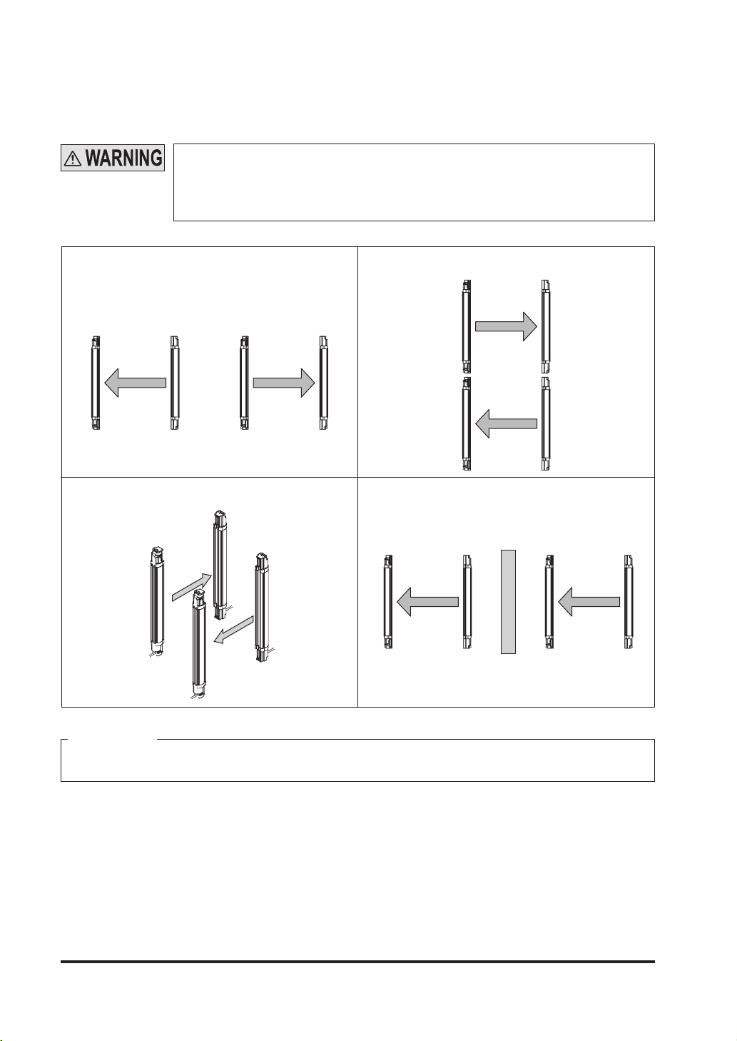
2-3-4 Device Placement
This is the conguration when two or more sets of emitter and receiver facing each other are placed
without series or parallel connection between them. It is used for the case that there is a problem in
wiring or for system evaluation in case of addition of equipment. Perform an operation test by referring to “2-6-2 Operation Test.”
Refer to the examples of device placement given below and understand them
●
thoroughly before installing the devices. Improper sensor placement could
cause device malfunction, which can result in death or serious injury.
If this device is used in multiple sets, arrange them to avoid mutual interference.
●
If mutual interference occurs, it can result in death or serious injury.
<Example of device placement>
1) Install emitter and the receiver back to back 2) Arrange the emitter and the receiver vertically on
opposite sides.
Receiver Emitter Emitter Receiver
3) Arrange the emitter and the receiver horizontally on
opposite sides.
Receiver
Emitter
Receiver
Emitter
4) Install a barrier
Receiver
Emitter
Receiver
Emitter Receiver Emitter
Barrier
Receiver
Emitter
<Reference>
The above gures are just examples of device placement. If there are any questions or problems, please
contact our ofce.
19 © Panasonic Electric Works SUNX Co., Ltd. 2010 MJE-SF4BGV2 No.0018-69V
Page 21
2-4 Mounting
2-4-1 Mounting of the Mounting Bracket
For selecting the appropriate mounting bracket matched to the installation nvi-
●
ronment, the mounting bracket is not incorporated in this device. Please pur-
chase the optional mounting bracket to t on the mounting environment.
Do not apply the load such as forced bending to the cable of this device. Apply-
●
ing improper load could cause the wire breakage.
The minimum bending radius of the cable is R6mm. Mount the device consider-
●
ing the cable bending radius.
<Reference>
Mount the emitter and the receiver at the same level and parallel to each other. The effective aperture
●
angle of this device is ±2.5° or less for a sensing distance of 3m or more.
Unless otherwise specied, the following mounting procedure is common for both emitter and receiver. For the
●
preparation of the mounting, prepare the mounting holes on the mounting surface by referring to “6-3 Dimensions.”
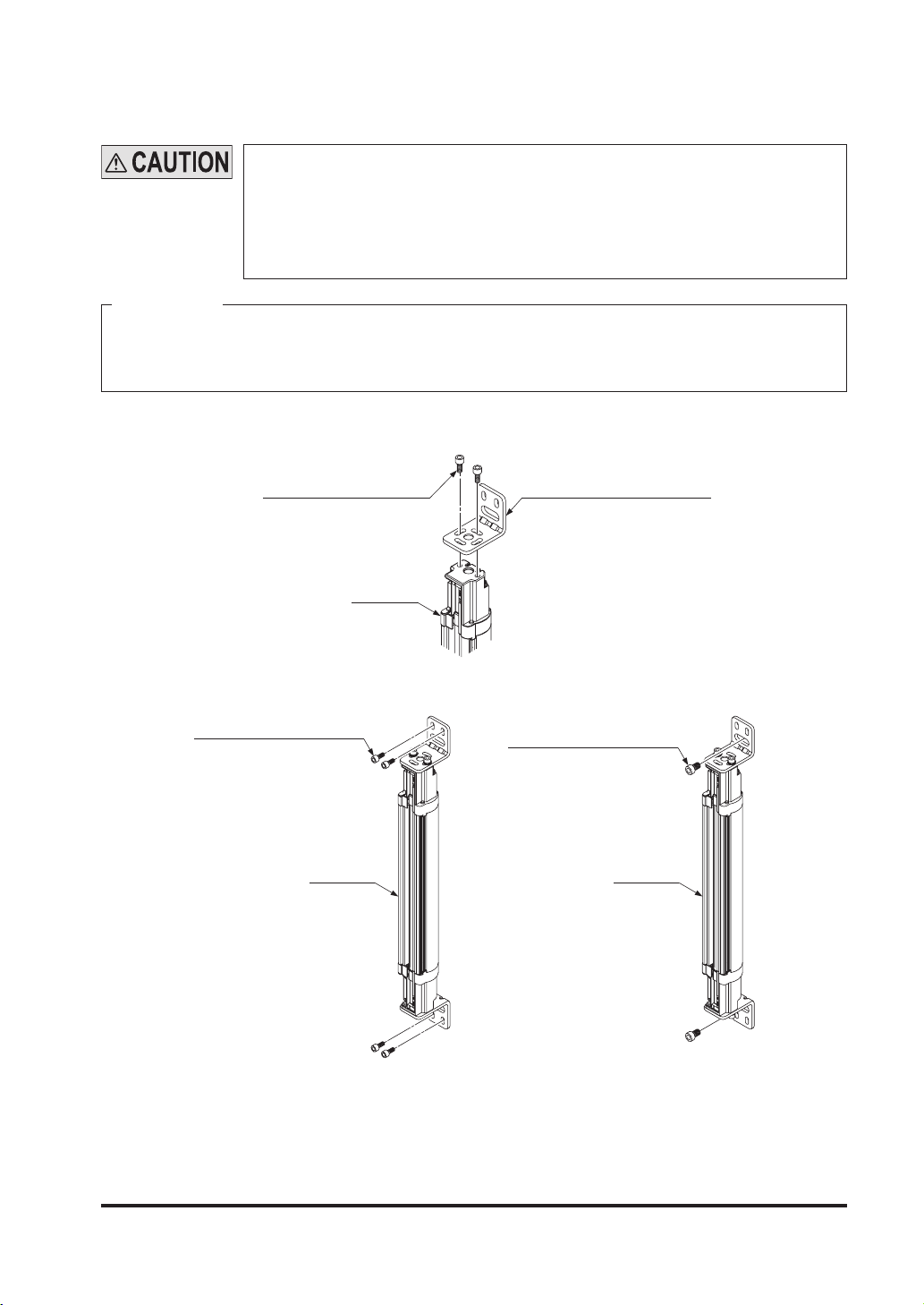
<In case of using standard ell mounting bracket (MS-SF4BG-1) (optional)>
1.
Temporary joint with two of hexagon-socket head bolts for horizontal angle adjustment [M5 (length: 10mm)]
Hexagon-socket head bolt
[M5 (length: 10mm)]
Main body
standard ell mounting bracket
(MS-SF4BG-1) (Optional)
2. Mount the standard ell mounting bracket on mounting surface with two of hexagon-socket
head bolts [M5 (purchase separately)] or one of [M8 (purchase separately)].
Hexagon-socket head bolt
[M5 (purchase separately)]
Main body
Hexagon-socket head bolt
[M8 (purchase separately)]
Main body
3. After light axis adjustment, tighten two of hexagon-socket head bolts for horizontal angle
adjustment [M5 (length: 10mm)]
The tightening torque should be 3N・m or less.
Note: For the models that the intermediate supporting bracket (MS-SF4BG-2) is enclosed with, be sure to use the
intermediate supporting bracket (MS-SF4BG-2). For details, refer to <In case of using intermediate
supporting bracket (MS-SF4BG-2) (accessory)>.
20© Panasonic Electric Works SUNX Co., Ltd. 2010 MJE-SF4BGV2 No.0018-69V
Page 22
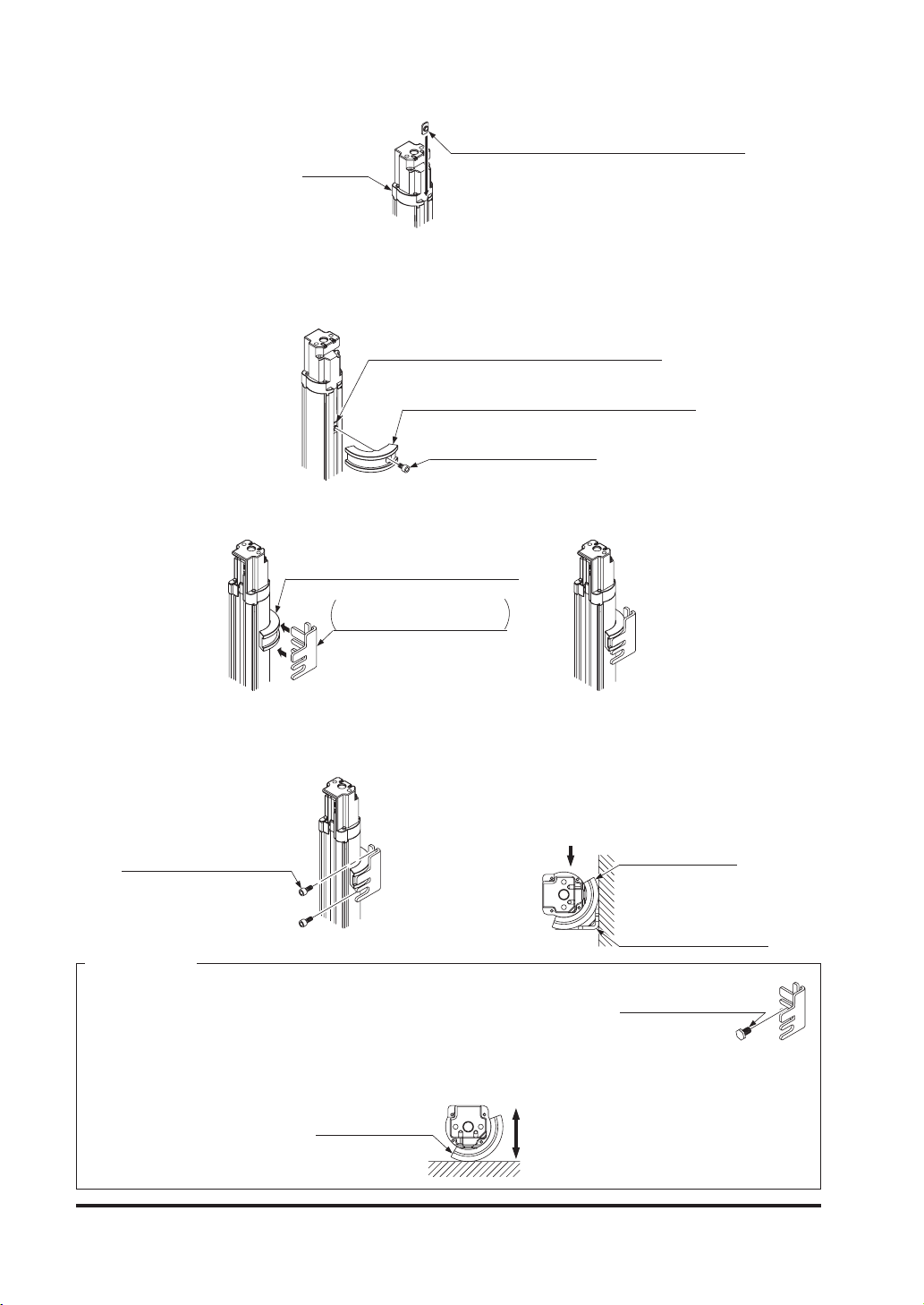
<In case of using intermediate supporting bracket (MS-SF4BG-2) (accessory)>
1. Insert a slot nut (accessory of intermediate supporting bracket) to back side of this product.
Slot nut
(Accesorry of intermediate supporting bracket)
Main body
2. Fix the slot nut inserted on back side of this product and the intermediate supporting bracket
with a hexagon-socket head bolt [M5 (length: 8mm)].
The tightening torque should be 3N·m or less.
About mounting position of intermediate supporting bracket, refer to “6-3 DIMENSIONS”.
Slot nut
(Accesorry of intermediate supporting bracket)
Intermediate supporting bracket
(Accesorry of intermediate supporting bracket)
Hexagon-socket head bolt
[M5 (length: 8mm)]
3. Insert and t the intermediate ell mounting bracket to concave portion of intermediate sup-
porting bracket.
Intermediate supporting bracket
(Accesorry of intermediate supporting bracket)
Intermediate ell bracket
Accesorry of intermediate
supporting bracket
Slide
<Inseted state>
4. Mount the intermediate ell bracket on the mounting surface with two of hexagon-socket head
bolts [M5 (purchase separately)] or one of [M8 (purchase separately)].
<Example>
In case the wight is on side of this product shown below,
mount the intermediate ell bracket to hold this product.
Hexagon-socket head bolt
[M5] (purchase separately)
Load
Beam-axis side
Intermediate
supporting bracket
Mounting surface
Intermediate ell bracket
<Reference>
In case using hexagon-socket head bolts [M8] to mount the Intermediate
●
ell bracket. Temporary joint the Intermediate ell bracket before conduct
Hexagon-socket bolt [M8]
(purchase separately)
step 3.
In case the wight is on the mounting surface vertically or vibrated vertically, the mounting of the interme-
●
diate ell bracket is not required.
Beam-axis side
Intermediate
supporting bracket
Vibration
and load
Mounting
surface
21 © Panasonic Electric Works SUNX Co., Ltd. 2010 MJE-SF4BGV2 No.0018-69V
Page 23
2-4-2 Mounting of the Bottom Cap Cable (Optional)
The cable is not enclosed with this device.
Mount the bottom cap cable (optional) in accordance with the following procedure.
Do not lose any screws during extension / dismantling.
●
The bottom cap cables are distinguished with the color of the connectors, the
●
color of the connector for emitter is gray and that of the receiver is black. Connect the cable to emitter and receiver without fail using their colors as the guide.
<Reference>
There are two types of the bottom cap cable, 8-core type and 12-core type, and in addition to these types,
two more types are available for the bottom cap cable, discrete wire type and connector type. Select the
bottom cap cable as usage.
The length of the bottom cap cable differs depending on the model No.
Type Model No. Cable length (m)
SFB-CCB3 3
Discrete wire type
8-core
Connector type
12-core
Discrete wire type
Connector type SFB-CB05-MU 0.5
<Mounting method>
1. Insert the connector of the bottom cap cable (optional) into the connector of this device.
When inserting the connector, t the cable to the groove of this device.
SFB-CCB7 7
SFB-CCB10 10
SFB-CCB15 15
SFB-CB05 0.5
SFB-CB5 5
SFB-CB10 10
SFB-CCB3-MU 3
SFB-CCB7-MU 7
Bottom cap cable
(Optional)
Connector
Connector
Cable
Main body
Groove
2. Tighten the two M2.6 screws. The tightening torque should be 0.3N·m or less.
M2.6 screw
Enclosed with the
bottom cap cable
22© Panasonic Electric Works SUNX Co., Ltd. 2010 MJE-SF4BGV2 No.0018-69V
Page 24

2-4-3 Extension and Dismantling of Sensor (Series Connection)
This section describes the extension method of the series connection using the options.
For constructing the series connection, the following procedure is required.
Do not lose any screws during extension / dismantling work.
Furthermore, do not mix emitters and receivers to mount in series connection.
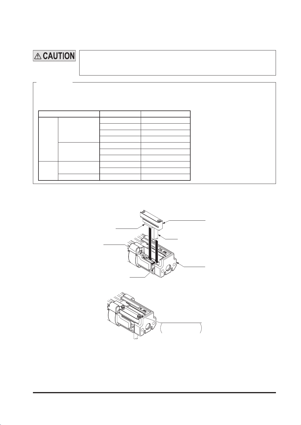
<Mounting method of cable for series connection>
Replace the cable for series connection (SFB-CSL□).
1. Loosen the two M2.6 screws of the end cap on the main sensor (emitter and receiver to
which the synchronization line has been connected), and then remove the end cap from the
device.
End cap
Main sensor
M2.6 screw
2. Insert the connector of the cable for series connection (SFB-CSL□) (optional) into the con-
nector. When inserting the connector, t the cable into the groove of this device.
Cable for serial connection
(SFB-CSL□) (Optional)
Connector
Connector
Groove
Cable
Sub sensor
(Bottom side)
Cable
Groove
Main sensor
(Upper side)
Connector
Connector
3. Tighten each two M2.6 screws. The tightening torque should be 0.3N·m or less.
M2.6 screw
Enclosed with the cable
for sires connection
Sub sensor
(Bottom side)
Main sensor
(Upper side)
23 © Panasonic Electric Works SUNX Co., Ltd. 2010 MJE-SF4BGV2 No.0018-69V
Page 25
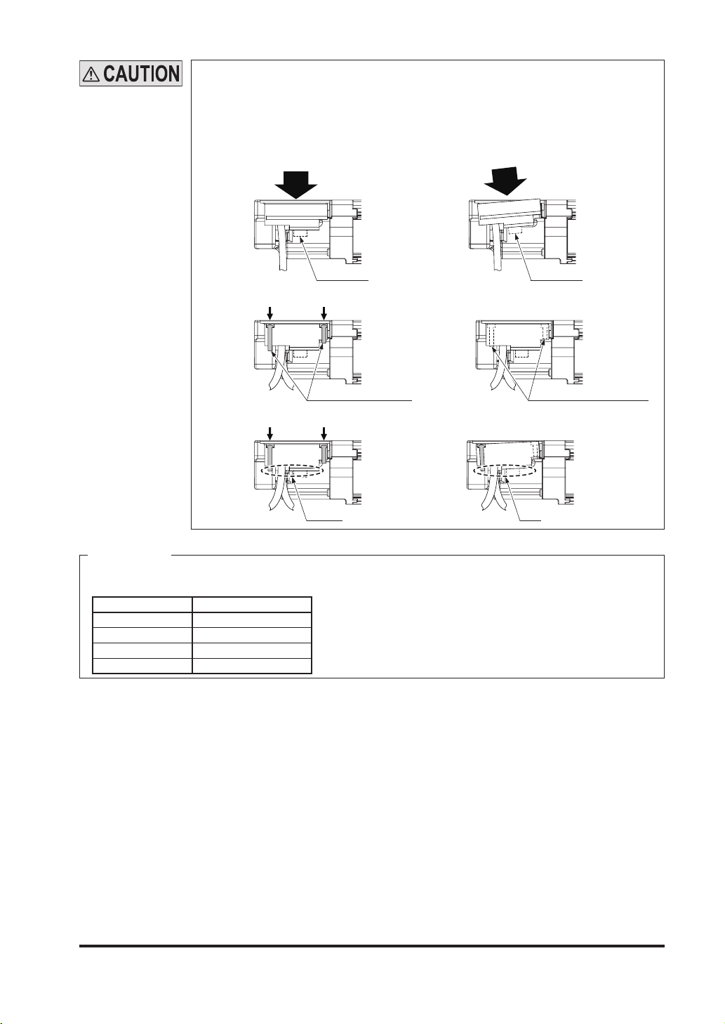
Take care that the shape of the connectors for the bottom side and for the end
●
cap side on the cable for series connection (SFB-CSL□) is different.
The cable for series connection (SFB-CSL□) cannot be extended.
●
When the cable for series connection (SFB-CSL□) is inserted to the main sen-
●
sor, take care of the following. If inserted without care, the connector pins may
bend.
1) Do not insert the connector part aslant.
Good
2) Do not pull the cables before tightening the M2.6 screws.
Good
Fixed with M2.6 screws Not xed with M2.6 screws
3) Do not insert the connector incorrectly and tighten the M2.6 screws.
Good
No gap Gap
<Reference>
There is no difference in the cable for series connection for the emitter and the receiver.
The length of the cable for series connection differs depending on the model No.
Model No. Cable Length (mm)
SFB-CSL01 100
SFB-CSL05 500
SFB-CSL1 1,000
SFB-CSL5 5,000
Not good
ConnectorConnector
Not good
Not good
<Dismantling the cable for series connection>
1. For dismantling the cable for series connection, follow the above procedure of <Mounting
method of cable for series connection> in reverse.
24© Panasonic Electric Works SUNX Co., Ltd. 2010 MJE-SF4BGV2 No.0018-69V
Page 26
2-5 Wiring
Earth the machine or the support where the device is mounted on to frame
●
ground (F.G.). Failure to do so could cause the malfunction of the device by
noise, resulting in death or serious injury.
Furthermore, the wiring should be done in a metal box connected to the frame
ground (F.G.).
Take countermeasure against the system to be applied for this device so as not
●
to carry out the dangerous performance caused by the earth failure. Failure to
do so could cause invalid for the system stop, resulting in death or serious injury.
In order that the output is not turned ON due to earth fault of control output
●
(OSSD 1 / 2) wires, be sure to ground to 0V side (PNP output) / +24V side (NPN
output).
Make sure to insulate the ends of the unused lead wires.
<Reference>
Use a safety relay unit or an equivalent control circuit in safety for FSD.
2-5-1 Power Supply Unit
Wire correctly using a power supply unit which conforms to the laws and standards of the region where this device is to be used. If the power supply unit is
non-conforming or the wiring is improper, it can cause damage or malfunction of
this device.
<Reference>
A specialist who has the required electrical knowledge should perform the wiring.
The power supply unit must satisfy the conditions given below.
1) Power supply unit authorized in the region where this device is to be used.
2) Power supply unit SELV (safety extra low voltage) / PELV (protected extra low voltage) conforming to EMC Directive and Low-voltage Directive (only for requiring CE marking conformation).
3) Power supply unit conforming to the Low-voltage Directive and with an output of 100VA or less.
4) The frame ground (F.G.) terminal must be connected to ground when using a commercially
available switching regulator.
5) Power supply unit with an output holding time of 20ms or more.
6) In case a surge is generated, take countermeasures such as connecting a surge absorber to
the origin of the surge.
7) Power supply unit corresponding to CLASS 2 (only for requiring UL Listing Mark / C-UL US Listing Mark conformation).
25 © Panasonic Electric Works SUNX Co., Ltd. 2010 MJE-SF4BGV2 No.0018-69V
Page 27
2-5-2 I/O Circuit Diagrams and Output Waveform
<In case of using I/O circuit for PNP output>
Emitter
Connector pin No.
Color code
(Brown) +V
(Red) Muting lamp output
*S1
(Yellow-green / Black) Auxiliary output
*S1 *S1
0.22μF
Main circuit
0.22μF
0.22μF
Receiver
Main circuit
470Ω
470Ω
470Ω
0.047μF
0.047μF
0.22μF
1kΩ
1kΩ
470Ω
(Gray) Interference prevention +
(Gray / Black) Interference prevention -
(Yellow) Override input
(Pale purple) Interlock setting input
(Pink) Emission halt input / Reset input
(Shield) Output polarity setting wire
(Blue) 0V
(Orange) Synchronization +
(Orange / black) Synchronization -
Users’ circuitInternal circuit
(Orange / Black)
Synchronization -
(Orange) Synchronization +
(Brown) +V
(Gray) Interference prevention +
(Gray / Black) Interference prevention -
(Sky-bule / White) Muting input A
(Sky-bule / Black) Muting input B
(Yellow-green) External device monitor input
(Black) Control output 1 (OSSD 1)
(White) Control output 2 (OSSD 2)
(Shield) Output polarity setting wire
(Blue) 0V
*S1
*S1
K1
K2
Load
K2
K1
+
-
24V DC
±10%
Users’ circuitInternal circuit
*S1
Switch S1
Emission halt input / Reset input
●
For manual reset: Vs to Vs - 2.5V (sink current 5mA or less) : Emission halt (Note 1), Open: Emission
For auto-reset: Vs to Vs - 2.5V (sink current 5mA or less) : Emission (Note 1), Open: Emission halt
Interlock setting input, Override input, Muting input A / B, External device monitor input
●
Vs to Vs - 2.5V (sink current 5mA or less): Valid (Note 1), Open: Invalid
Notes: 1) Vs is the applying supply voltage.
2) The circuit diagram shown above is for 12-core cable to be used. For 8-core cable, red, yellow, gray,
gray / black, sky-blue / white, sky-blue / black, there is no lead wire.
<Reference>
K1, K2: External device (Forced guided relay or magnetic contactor)
26© Panasonic Electric Works SUNX Co., Ltd. 2010 MJE-SF4BGV2 No.0018-69V
Page 28
<In case of using I/O circuit for NPN output>
Emitter
Main circuit
Receiver
Connector pin No.
0.22μF
0.22μF
0.22μF
470Ω
470Ω
470Ω
Color code
(Brown) +V
(Shield) Output polarity setting wire
(Yellow) Override input
(Pale purple) Interlock setting input
(Pink) Emission halt input / Reset input
(Gray) Interference prevention +
(Gray / Black) Interference prevention -
(Yellow-green / Black) Auxiliary output
(Red) Muting lamp output
(Blue) 0V
(Orange) Synchronization +
(Orange / black) Synchronization -
Users’ circuitInternal circuit
(Orange / Black) Synchronization -
(
Orange) Synchronization +
(Brown) +V
(Shield) Output polarity setting wire
(Black) Control output 1 (OSSD 1)
*S1
*S1 *S1
Load
K1
K2
+
-
24V DC
±10%
(White) Control output 2 (OSSD 2)
Main circuit
0.22μF
0.047μF
0.047μF
*S1
Switch S1
Emission halt input / Reset input
●
For manual reset: 0 to +1.5V (source current 5mA or less): Emission halt, Open: Emission
For auto-reset: 0 to +1.5V (source current 5mA or less): Emission, Open: Emission halt
Interlock setting input, Override input, Muting input A / B, External device monitor input
●
0 to + 1.5V (source current: 5mA or less): Valid, Open: Invalid
Note: The circuit diagram shown above is for 12-core cable to be used. For 8-core cable, red, yellow, gray, gray /
black, sky-blue / white, sky-blue / black, there is no lead wire.
470Ω
1kΩ
1kΩ
(Gray) Interference prevention +
(Gray / Black) Interference prevention -
(Yellow-green) External device monitor input
(Sky-bule / White) Muting input A
(Sky-bule / Black) Muting input B
(Blue) 0V
Users’ circuitInternal circuit
*S1
*S1
K1
K2
<Reference>
K1, K2: External device (Forced guided relay or magnetic contactor)
27 © Panasonic Electric Works SUNX Co., Ltd. 2010 MJE-SF4BGV2 No.0018-69V
Page 29
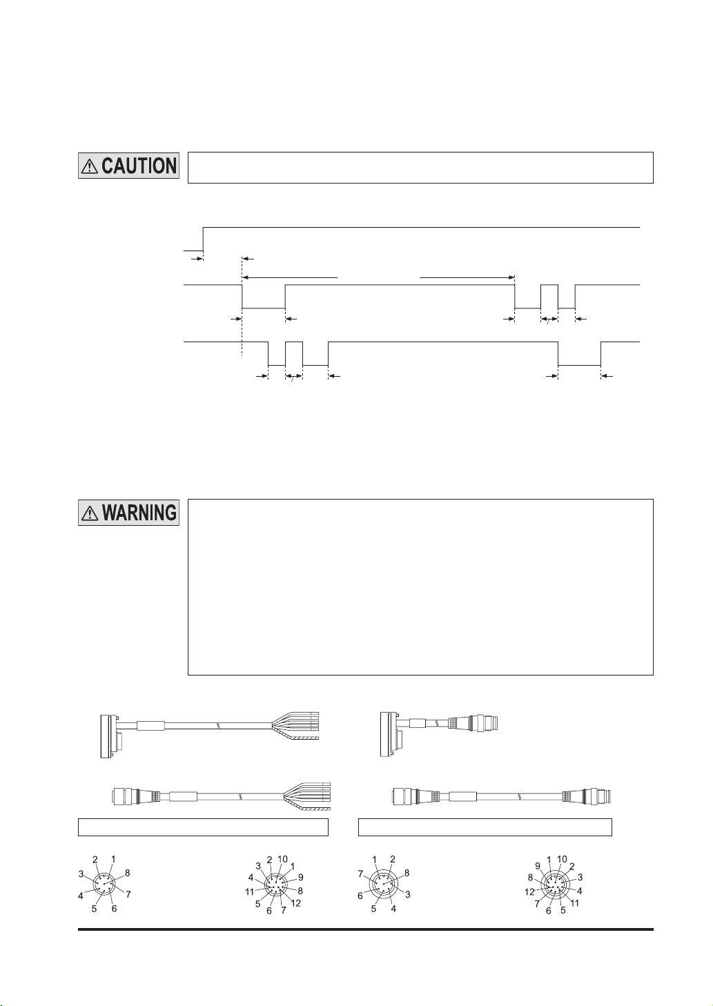
<Output waveform [control output (OSSD 1 / 2) ON]>
Since the receiver performs the self-diagnosis of the output circuit when the device is in light receiving
status (ON status), the output transistor becomes OFF status periodically. (Refer to the gure below.)
When the OFF signal is fed back, the receiver judges the output circuit as normal. When the
OFF signal is not fed back, the receiver judges either the output circuit or wiring as error, and
the control output (OSSD 1 / 2) maintains OFF status.
Perform the wiring with paying attention to the input response time of the machine to be
connected to this device, since the OFF signal of this device might cause malfunction.
<Timing chart>
Light received
status
Control output 1
(OSSD 1)
Control output 2
(OSSD 2)
Beam
received
Beam
blocked
ON
OFF
ON
OFF
Approx. 40μs
80 to 90 ms
Approx. 100μs
Approx. 40μs
Approx. 5.4ms
Approx. 60μs
Approx. 60μs Approx. 40μs
Approx. 40μs
Approx. 100μs
2-5-3 Wiring · Connecting Procedure and Connector Pin Arrangement
Connect the mating cable (with connector on one end or connector on both ends) to the connector of the bottom cap cable which is mounted on this device (emitter and receiver).
Wire the other side of the mating cable according to the customer’s application referring to the
connector pin arrangement given below.
When extending the cable, use the exclusive cable up to the total length of 50m (for
●
each emitter / receiver). Extending the cable longer than 50m may cause malfunction, which can result in death or serious injury. Besides, if two sets of the devices are
connected in series, up to total length of 30m (for each emitter / receiver) is allowed
for use, and if three sets of the devices are connected, up to total length of 20m (for
each emitter / receiver) is allowed for use. Extending the cable longer than the length
specied may cause malfunction, which can result in death or serious injury.
In case the muting lamp is used, a total length should be 40m or less (for each
●
emitter / receiver).
When the synchronization + wire (orange) and synchronization - wire (orange
●
/ black) is extended with a cable other than exclusive cable, use a 0.2mm2 or
more shielded twisted pair cable.
Bottom cap cable / discrete wire Bottom cap cable / connector
A side
Extension cable with connector on one end Extension cable with connector on both ends
B side
Connector at A side (for emitter / receiver) Connector at B side (for emitter / receiver)
<8-core> <12-core> <8-core> <12-core>
A sideB side
28© Panasonic Electric Works SUNX Co., Ltd. 2010 MJE-SF4BGV2 No.0018-69V
Page 30

<8-core cable (SFB-CC□ )>
Cable / connector color
Emitter Gray / Gray
Receiver
Gray (with black stripe)
/Black
<12-core cable (SFB-CC□-MU )>
Cable / connector color
Emitter Gray / Gray
Receiver
Gray (with black stripe)
/ Black
Connector
Pin No.
1 Pale purple Interlock setting input
2 Brown +V
3 Pink Emission halt input / Reset input
4 Yellow-green / Black Auxiliary output
5 Orange Synchronization +
6 Orange / Black Synchronization 7 Blue 0V
8 (Shield) Output polarity setting wire
1 White Control output 2 (OSSD 2)
2 Brown +V
3 Black Control output 1 (OSSD 1)
4 Yellow-green External device monitor input
5 Orange Synchronization +
6 Orange / Black Synchronization 7 Blue 0V
8 (Shield) Output polarity setting wire
Connector
Pin No..
1 Pale purple Interlock setting input
2 Brown +V
3 Pink Emission halt input / Reset input
4 Yellow-green / Black Auxiliary output
5 Orange Synchronization +
6 Orange / Black Synchronization 7 Blue 0V
8 (Shield) Output polarity setting wire
9 Gray Interference prevention +
10 Gray / Black Interference prevention -
11 Yellow Override input
12 Red Muting lamp output
1 White Control output 2 (OSSD 2)
2 Brown +V
3 Black Control output 1 (OSSD 1)
4 Yellow-green External device monitor input
5 Orange Synchronization +
6 Orange / Black Synchronization 7 Blue 0V
8 (Shield) Output polarity setting wire
9 Gray Interference prevention +
10 Gray / Black Interference prevention -
11 Sky-blue / White Muting input A
12 Sky-blue / Black Muting input B
Color code Description
Color code Description
<Reference>
The connectors can be distinguished from their colors as follows:
●
Connector for emitter: gray, connector for receiver: black
For details of the bottom cap cable, the cable with connector on one end, and the cable with connector
●
on both ends, refer to “6-2 Options.”
29 © Panasonic Electric Works SUNX Co., Ltd. 2010 MJE-SF4BGV2 No.0018-69V
Page 31

2-5-4 Basic Wiring
This is the general conguration using one set of the emitter and receiver facing each other.
The control output (OSSD 1 / 2) turns OFF if the light is blocked, while it automatically turns ON
if receives the light.
The auxiliary output is used to invalid the external device monitor function. At this time, set the
auxiliary output with “negative logic of the control output” (factory setting). The auxiliary output
cannot be connected to external devices.
<For PNP output>
(Gray) Interference prevention +
(Gray / Black) Interference prevention -
(Red) Muting lamp output
(Yellow) Override input
(Pale purple) Interlock setting input
(Brown) +V
Receiver
Gray cable
Gray cable
with black line
Emitter
(Pink) Emission halt input / Reset input
(Shield) Output polarity setting wire
(Blue) 0V
(Yellow-green / Black) Auxiliary output
(Orange) Synchronization +
(Orange / Black) Synchronization (Orange / Black) Synchronization (Orange) Synchronization +
(Yellow-green) External device monitor input
(Brown) +V
(Black) Control output 1 (OSSD 1)
(White) Control output 2 (OSSD 2)
(Shield) Output polarity setting wire
(Blue) 0V
(Sky-bule / White) Muting input A
(Sky-bule / Black) Muting input B
(Gray / Black) Interference prevention (Gray) Interference prevention +
K1
K2
+
-
24V DC
±10
%
Interlock function Invalid (Auto-reset)
External device monitor function Invalid
Auxiliary output Cannot be used
Note: The circuit diagram shown above is for 12-core cable to be used. For 8-core cable, red, yellow, gray, gray /
black, sky-blue / white, sky-blue / black, there is no lead wire.
30© Panasonic Electric Works SUNX Co., Ltd. 2010 MJE-SF4BGV2 No.0018-69V
Page 32

<For NPN output>
Emitter
Receiver
Gray cable
Gray cable
with black line
(Gray) Interference prevention +
(Gray / Black) Interference prevention -
(Red) Muting lamp output
(Yellow) Override input
(Pale purple) Interlock setting input
(Brown) +V
(Shield) Output polarity setting wire
(Pink) Emission halt input / Reset input
(Blue) 0V
(Yellow-green / Black) Auxiliary output
(Orange) Synchronization +
(Orange / Black) Synchronization (Orange / Black) Synchronization -
(Orange) Synchronization +
(Yellow-green) External device monitor input
(Brown) +V
(Black) Control output 1 (OSSD 1)
(White) Control output 2 (OSSD 2)
(Shield) Output polarity setting wire
(Blue) 0V
(Sky-bule / White) Muting input A
(Sky-bule / Black) Muting input B
(Gray / Black) Interference prevention (Gray) Interference prevention +
K1
K2
+
-
24V DC
±10
%
Interlock function Invalid (Auto-reset)
External device monitor function Invalid
Auxiliary output Cannot be used
Note: The circuit diagram shown above is for 12-core cable to be used. For 8-core cable, red, yellow, gray, gray /
black, sky-blue / white, sky-blue / black, there is no lead wire.
31 © Panasonic Electric Works SUNX Co., Ltd. 2010 MJE-SF4BGV2 No.0018-69V
Page 33

2-5-5 Wiring for Manual Reset (Interlock is Valid)
(Wiring Example of the Control Category 4)
This is the general conguration using one set of the emitter and receiver facing each other.
The control output (OSSD 1 / 2) turns OFF if the light is blocked.
<For PNP output>
(Gray) Interference prevention +
(Gray / Black) Interference prevention -
(Red) Muting lamp output
(Yellow) Override input
(Brown) +V
Receiver
Gray cable
Gray cable
with black line
Emitter
(Pale purple) Interlock setting input
(Pink) Emission halt input / Reset input
(Yellow-green / Black) Auxiliary output
(Shield) Output polarity setting wire
(Blue) 0V
(Orange) Synchronization +
(Orange / Black) Synchronization (Orange / Black) Synchronization -
(Orange) Synchronization +
(Yellow-green) External device monitor input
(Brown) +V
(Black) Control output 1 (OSSD 1)
(White) Control output 2 (OSSD 2)
(Shield) Output polarity setting wire
(Blue) 0V
(Sky-bule / White) Muting input A
(Sky-bule / Black) Muting input B
(Gray / Black) Interference prevention (Gray) Interference prevention +
Load
K1 K2
K1
K2
*S1
+
-
24V DC
±10
%
Interlock function Valid (Manual reset)
External device monitor function Valid
Auxiliary output Can be used
The device output is selected depending on the connecting state of the output polarity setting wire
(shield). Incorrect wiring may cause the lockout state.
* Symbols
Switch S1
Vs to Vs - 2.5V (sink current 5mA or less): Emission halt (Note 1), Open: Emission
K1, K2: External device (Forced guided relay or magnetic contactor)
Notes: 1) Vs is the applying supply voltage.
2) The circuit diagram shown above is for 12-core cable to be used. For 8-core cable, red, yellow, gray, gray /
black, sky-blue / white, sky-blue / black, there is no lead wire.
3) For resetting, refer to “3-2 Interlock Function.”
32© Panasonic Electric Works SUNX Co., Ltd. 2010 MJE-SF4BGV2 No.0018-69V
Page 34

<For NPN output>
Emitter
Receiver
Gray cable
Gray cable
with black line
(Gray) Interference prevention +
(Gray / Black) Interference prevention (Red) Muting lamp output
(Yellow) Override input
(Brown) +V
(Yellow-green / Black) Auxiliary output
(Shield) Output polarity setting wire
(Pink) Emission halt input / Reset input
(Pale purple) Interlock setting input
(Blue) 0V
(Orange) Synchronization +
(Orange / Black) Synchronization (Orange / Black) Synchronization (Orange) Synchronization +
(Yellow-green) External device monitor input
(Brown) +V
(Black) Control output 1 (OSSD 1)
(White) Control output 2 (OSSD 2)
(Shield) Output polarity setting wire
(Blue) 0V
(Sky-bule / White) Muting input A
(Sky-bule / Black) Muting input B
(Gray / Black) Interference prevention (Gray) Interference prevention +
Load
K1
K2
*S1
K1 K2
+
-
24V DC
±10
%
Interlock function Valid (Manual reset)
External device monitor function Valid
Auxiliary output Can be used
The device output is selected depending on the connecting state of the output polarity setting wire
(shield). Incorrect wiring may cause the lockout state.
* Symbols
Switch S1
0 to +1.5V (source current 5mA or less): Emission halt, Open: Emission
K1, K2: External device (Forced guided relay or magnetic contactor)
Notes: 1) The circuit diagram shown above is for 12-core cable to be used. For 8-core cable, red, yellow, gray, gray /
2) For resetting, refer to “3-2 Interlock Function.”
black, sky-blue / white, sky-blue / black, there is no lead wire.
33 © Panasonic Electric Works SUNX Co., Ltd. 2010 MJE-SF4BGV2 No.0018-69V
Page 35

2-5-6 Series Connection
(Wiring Example of the Control Category 4)
[Connectable up to 3 sets of the devices (however, 192 beam channels max.)]
This is the conguration for connecting multiple sets of emitters and receivers facing each other
in series. It is used when the dangerous part can be entered from two or more directions. If any
of the sets is in light blocked status, the control output (OSSD 1 / 2) turns OFF.
For series connection, connect the emitter and emitter, receiver and receiver respectively using the exclusive cable (SFB-CSL□) for series connection. Wrong
connection could generate the non-sensing area, resulting in death or serious injury.
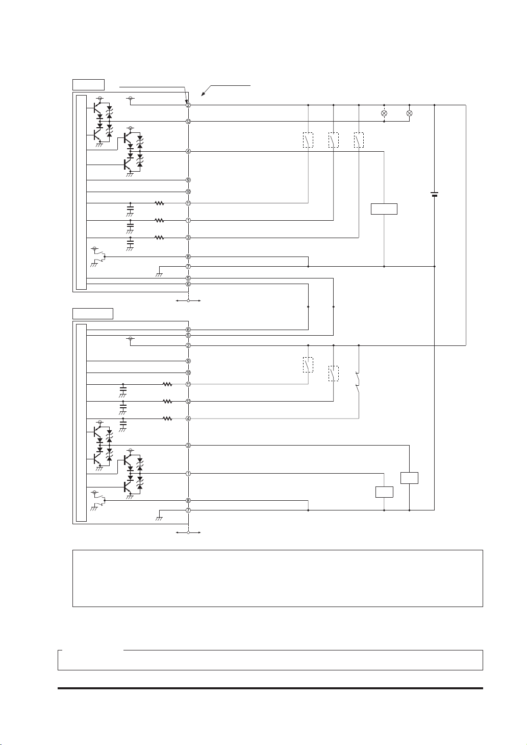
<For PNP output>
(Gray) Interference prevention +
(Gray / Black) Interference prevention -
Gray
cable
Receiver 2 sub sensor
Emitter 2 sub sensor
Receiver 1 main sensor
Emitter 1 main sensor
Gray cable
with black line
Interlock function Valid (Manual reset)
External device monitor function Valid
Auxiliary output Can be used
(Red) Muting lamp output
(Yellow) Override input
(Brown) +V
(Pale purple) Interlock setting input
(Pink) Emission halt input / Reset input
(Yellow-green / Black) Auxiliary output
(Shield) Output polarity setting wire
(Blue) 0V
(Orange) Synchronization +
(
Orange / Black) Synchronization (Orange / Black) Synchronization (Orange) Synchronization +
(Yellow-green) External device monitor input
(Brown) +V
(Black) Control output 1 (OSSD 1)
(White) Control output 2 (OSSD 2)
(Shield) Output polarity setting wire
(Blue) 0V
(Sky-bule / White) Muting input A
(Sky-bule / Black) Muting input B
(Gray / Black) Interference prevention (Gray) Interference prevention +
Load
K1
K2
*S1
K1 K2
+
-
24V DC
±10
%
The device output is selected depending on the connecting state of the output polarity setting wire
(shield). Incorrect wiring may cause the lockout state.
* Symbols
Switch S1
Vs to Vs - 2.5V (sink current 5mA or less): Emission halt (Note 1), Open: Emission
K1, K2: External device (Forced guided relay or magnetic contactor)
Notes: 1) Vs is the applying supply voltage.
2) The circuit diagram shown above is for 12-core cable to be used. For 8-core cable, red, yellow, gray, gray /
black, sky-blue / white, sky-blue / black, there is no lead wire.
3) For resetting, refer to “3-2 Interlock Function.”
34© Panasonic Electric Works SUNX Co., Ltd. 2010 MJE-SF4BGV2 No.0018-69V
Page 36

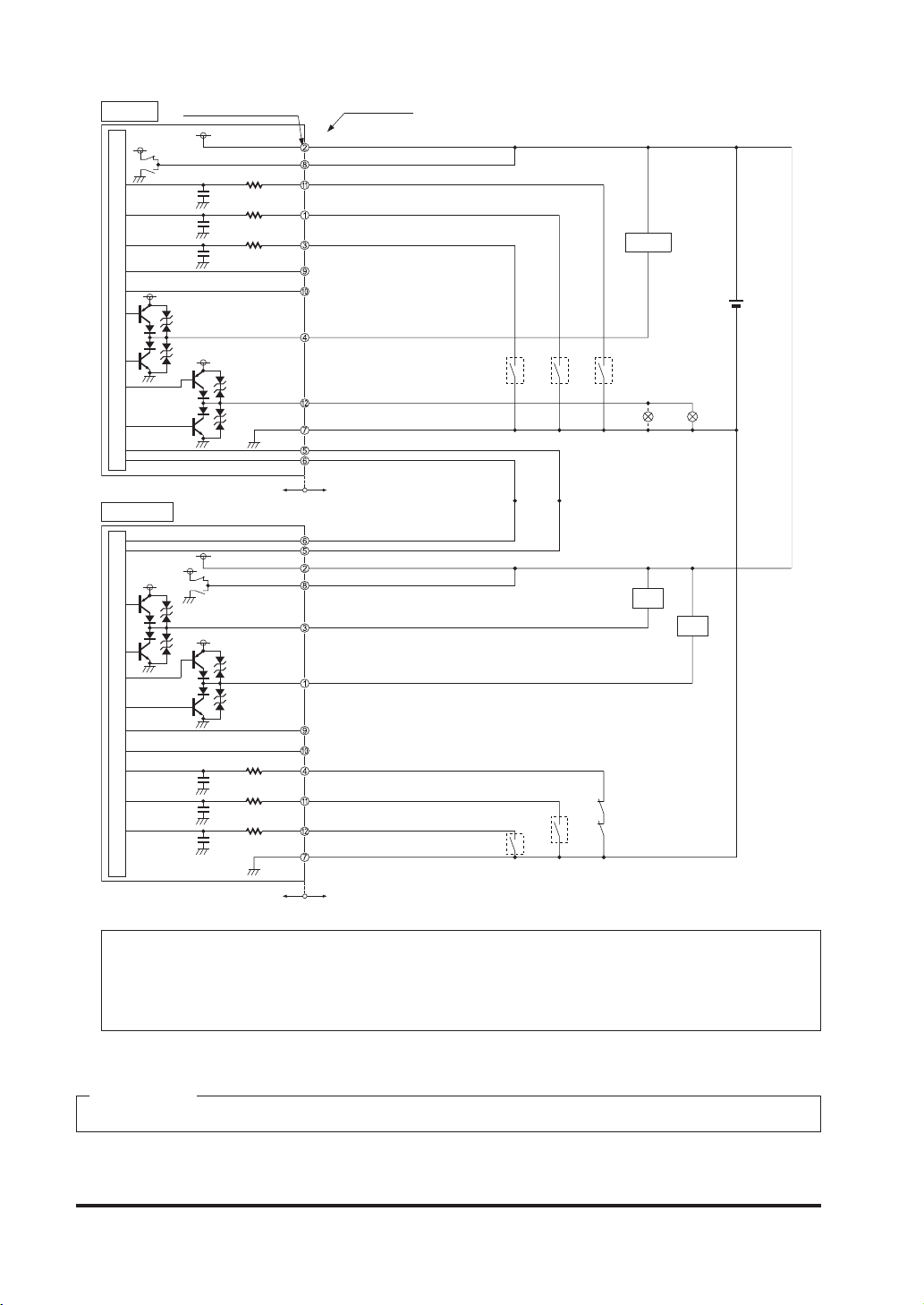
<For NPN output>
Gray
cable
Receiver 2 sub sensor
Emitter 2 sub sensor
Receiver 1 main sensor
Emitter 1 main sensor
Gray cable
with black line
(Gray) Interference prevention +
(Gray / Black) Interference prevention (Red) Muting lamp output
(Yellow) Override input
(Brown) +V
(Yellow-green / Black) Auxiliary output
(Shield) Output polarity setting wire
(Pink) Emission halt input / Reset input
(Pale purple) Interlock setting input
(Blue) 0V
(Orange) Synchronization +
(Orange / Black) Synchronization (Orange / Black) Synchronization (Orange) Synchronization +
(Yellow-green) External device monitor input
(Brown) +V
(Black) Control output 1 (OSSD 1)
(White) Control output 2 (OSSD 2)
(Shield) Output polarity setting wire
(Blue) 0V
(Sky-bule / White) Muting input A
(Sky-bule / Black) Muting input B
(Gray / Black) Interference prevention (Gray) Interference prevention +
Load
K1
K2
*S1
K1 K2
+
-
24V DC
±10
%
Interlock function Valid (Manual reset)
External device monitor function Valid
Auxiliary output Can be used
The device output is selected depending on the connecting state of the output polarity setting wire
(shield) wire. Incorrect wiring may cause the lockout state.
* Symbols
Switch S1
0 to +1.5V (source current 5mA or less): Emission halt, Open: Emission
K1, K2: External device (Forced guided relay or magnetic contactor)
Notes: 1) The circuit diagram shown above is for 12-core cable to be used. For 8-core cable, red, yellow, gray, gray /
black, sky-blue / white, sky-blue / black, there is no lead wire.
2) For resetting, refer to “3-2 Interlock Function.”
35 © Panasonic Electric Works SUNX Co., Ltd. 2010 MJE-SF4BGV2 No.0018-69V
Page 37

2-5-7 Parallel Connection
(Wiring Example of the Control Category 4)
This is the conguration for connecting multiple sets of emitter and receiver facing each other
in parallel. It is used when there are two dangerous parts and each dangerous part can be entered from only one direction. By connecting the interference prevention line, up to three sets of
the devices can be connected. For the control output (OSSD 1 / 2), only the set of which light is
blocked turns OFF.
For parallel connection, connect the one receiver to the other connection using the
interference prevention line as shown in the gure on the next page. Wrong connection could generate the non-sensing area, resulting in death or serious injury.
36© Panasonic Electric Works SUNX Co., Ltd. 2010 MJE-SF4BGV2 No.0018-69V
Page 38

<For PNP output>
Master side
Emitter
Receiver
Gray cable
Gray cable
with black line
Slave side
Emitter
Receiver
Gray cable
Gray cable
with black line
(Gray) Interference prevention +
(Gray / Black) Interference prevention (Red) Muting lamp output
(Yellow) Override input
(Brown) +V
(Pale purple) Interlock setting input
(Pink) Emission halt input / Reset input
(Yellow-green / Black) Auxiliary output
(Shield) Output polarity setting wire
(Blue) 0V
(Orange) Synchronization +
(Orange / Black) Synchronization (Orange / Black) Synchronization (Orange) Synchronization +
(Yellow-green) External device monitor input
(Brown) +V
(Black) Control output 1 (OSSD 1)
(White) Control output 2 (OSSD 2)
(Shield) Output polarity setting wire
(Blue) 0V
(Sky-bule / White) Muting input A
(Sky-bule / Black) Muting input B
(Gray / Black) Interference prevention (Gray) Interference prevention +
(Note 1)
*S1
Load
K1
K2
*S1
Load
K1
K2
K1 K2
K1 K2
+
-
+
-
24V DC
±10
%
24V DC
±10
%
37 © Panasonic Electric Works SUNX Co., Ltd. 2010 MJE-SF4BGV2 No.0018-69V
Page 39

Interlock function Valid (Manual reset)
External device monitor function Valid
Auxiliary output Can be used
The device output is selected depending on the connecting state of the output polarity setting wire
(shield).
Incorrect wiring may cause the lockout state.
* Symbols
Switch S1
Vs to Vs - 2.5V (sink current 5mA or less): Emission halt (Note 2), Open: Emission
K1, K2: External device (Forced guided relay or magnetic contactor)
Notes: 1) If the interference prevention wire is extended, use a 0.2mm2 or more, shielded twisted pair cable.
2) Vs is the applying supply voltage.
3) For resetting, refer to “3-2 Interlock Function.”
38© Panasonic Electric Works SUNX Co., Ltd. 2010 MJE-SF4BGV2 No.0018-69V
Page 40

<For NPN output>
Master side
Emitter
Receiver
Gray cable
Gray cable
with black line
Slave side
Emitter
Receiver
Gray cable
Gray cable
with black line
(Gray) Interference prevention +
(Gray / Black) Interference prevention (Red) Muting lamp output
(Yellow) Override input
(Brown) +V
(Yellow-green / Black) Auxiliary output
(Shield) Output polarity setting wire
(Pink) Emission halt input / Reset input
(Pale purple) Interlock setting input
(Blue) 0V
(Orange) Synchronization +
(Orange / Black) Synchronization (Orange / Black) Synchronization (Orange) Synchronization +
(Yellow-green) External device monitor input
(Brown) +V
(Black) Control output 1 (OSSD 1)
(White) Control output 2 (OSSD 2)
(Shield) Output polarity setting wire
(Blue) 0V
(Sky-bule / White) Muting input A
(Sky-bule / Black) Muting input B
(Gray / Black) Interference prevention (Gray) Interference prevention +
(Note 1)
Load
K1
K2
Load
K1
K2
*S1
K1 K2
*S1
K1 K2
+
-
+
-
24V DC
±10
%
24V DC
±10
%
39 © Panasonic Electric Works SUNX Co., Ltd. 2010 MJE-SF4BGV2 No.0018-69V
Page 41

Interlock function Valid (Manual reset)
External device monitor function Valid
Auxiliary output Can be used
The device output is selected depending on the connecting state of the output polarity setting wire
(shield).
Incorrect wiring may cause the lockout state.
* Symbols
Switch S1
0 to +1.5V (source current 5mA or less): Emission halt, Open: Emission
K1, K2: External device (Forced guided relay or magnetic contactor)
Notes: 1) If the interference prevention wire is extended, use a 0.2mm2 or more, shielded twisted pair cable.
2) For resetting, refer to “3-2 Interlock Function.”
2-5-8 Series and Parallel Mixed Connection
(Wiring Example of the Control Category 4)
This is the conguration for connecting multiple sets of emitter and receiver facing each other in
mixed series and parallel combination. It is used when there are two or more dangerous parts
that can be entered from two or more directions. Up to three sets of the devices in total of the
series connection and parallel connection can be connected in combination. However, the total
number of beam channels available is 192. In case of series connection, if any of the sets is in
light blocked status, the control output (OSSD 1 / 2) turns OFF. In case of parallel connection,
for the control output (OSSD 1 / 2), only the set of which light is blocked turns OFF.
For series connection, connect the emitter and emitter, receiver and receiver
●
respectively using the exclusive cable (SFB-CSL□) for series connection as
shown in the figure on the next page. Wrong connection could generate the
non-sensing area, resulting in death or serious injury.
For parallel connection, connect the one receiver to the other connection using
●
the interference prevention line as shown in the gure on the next page. Wrong
connection could generate the non-sensing area, resulting in death or serious
injury
40© Panasonic Electric Works SUNX Co., Ltd. 2010 MJE-SF4BGV2 No.0018-69V
Page 42

<For PNP output>
Master side
Gray
cable
Receiver 2 sub sensor
Emitter 2 sub sensor
Receiver 1 main sensor
Emitter 1 main sensor
Gray cable
with black line
Slave side
Emitter
Receiver
Gray cable
Gray cable
with black line
(Gray) Interference prevention +
(Gray / Black) Interference prevention (Red) Muting lamp output
(Yellow) Override input
(Brown) +V
(Pale purple) Interlock setting input
(Pink) Emission halt input / Reset input
(Yellow-green / Black) Auxiliary output
(Shield) Output polarity setting wire
(Blue) 0V
(Orange) Synchronization +
(Orange / Black) Synchronization (Orange / Black) Synchronization (Orange) Synchronization +
(Yellow-green) External device monitor input
(Brown) +V
(Black) Control output 1 (OSSD 1)
(White) Control output 2 (OSSD 2)
(Shield) Output polarity setting wire
(Blue) 0V
(Sky-bule / White) Muting input A
(Sky-bule / Black) Muting input B
(Gray / Black) Interference prevention (Gray) Interference prevention +
(Note 1)
*S1
Load
K1
K2
*S1
Load
K1
K2
K1 K2
K1 K2
+
-
+
-
24V DC
±10
%
24V DC
±10
%
41 © Panasonic Electric Works SUNX Co., Ltd. 2010 MJE-SF4BGV2 No.0018-69V
Page 43

Interlock function Valid (Manual reset)
External device monitor function Valid
Auxiliary output Can be used
The device output is selected depending on the connecting state of the output polarity setting wire
(shield).
Incorrect wiring may cause the lockout state.
* Symbols
Switch S1
Vs to Vs - 2.5V (sink current 5mA or less): Emission halt (Note 2), Open: Emission
K1, K2: External device (Forced guided relay or magnetic contactor)
Notes: 1) If the interference prevention wire is extended, use a 0.2mm2 or more, shielded twisted pair cable.
2) Vs is the applying supply voltage.
3) For resetting, refer to “3-2 Interlock Function.”
42© Panasonic Electric Works SUNX Co., Ltd. 2010 MJE-SF4BGV2 No.0018-69V
Page 44

<For NPN output>
Master side
Gray
cable
Receiver 2 sub sensor
Emitter 2 sub sensor
Receiver 1 main sensor
Emitter 1 main sensor
Gray cable
with black line
Slave side
Emitter
Receiver
Gray cable
Gray cable
with black line
(Gray) Interference prevention +
(Gray / Black) Interference prevention (Red) Muting lamp output
(Yellow) Override input
(Brown) +V
(Yellow-green / Black) Auxiliary output
(Shield) Output polarity setting wire
(Pink) Emission halt input / Reset input
(Pale purple) Interlock setting input
(Blue) 0V
(Orange) Synchronization +
(Orange / Black) Synchronization (Orange / Black) Synchronization (Orange) Synchronization +
(Yellow-green) External device monitor input
(Brown) +V
(Black) Control output 1 (OSSD 1)
(White) Control output 2 (OSSD 2)
(Shield) Output polarity setting wire
(Blue) 0V
(Sky-bule / White) Muting input A
(Sky-bule / Black) Muting input B
(Gray / Black) Interference prevention (Gray) Interference prevention +
(Note 1)
Load
K1
K2
Load
K1
K2
:S1
K1 K2
*S1
K1 K2
+
-
+
-
24V DC
±10
%
24V DC
±10
%
43 © Panasonic Electric Works SUNX Co., Ltd. 2010 MJE-SF4BGV2 No.0018-69V
Page 45

Interlock function Valid (Manual reset)
External device monitor function Valid
Auxiliary output Can be used
The device output is selected depending on the connecting state of the output polarity setting wire
(shield).
Incorrect wiring may cause the lockout state.
* Symbols
Switch S1
0 to +1.5V (source current 5mA or less): Emission halt, Open: Emission
K1, K2: External device (Forced guided relay or magnetic contactor)
Notes: 1) If the interference prevention wire is extended, use a 0.2mm2 or more, shielded twisted pair cable.
2) For resetting, refer to “3-2 Interlock Function.”
44© Panasonic Electric Works SUNX Co., Ltd. 2010 MJE-SF4BGV2 No.0018-69V
Page 46

2-5-9 Wiring for Auto-reset (Interlock is Invalid)
(Wiring Example of the Control Category 4)
<For PNP output>
(Gray) Interference prevention +
(Gray / Black) Interference prevention (Red) Muting lamp output
(Yellow) Override input
(Pale purple) Interlock setting input
(Brown) +V
Emitter
Receiver
Gray cable
Gray cable
with black line
(Pink) Emission halt input / Reset input
(Yellow-green / Black) Auxiliary output
(Shield) Output polarity setting wire
(Blue) 0V
(Orange) Synchronization +
(Orange / Black) Synchronization (Orange / Black) Synchronization (Orange) Synchronization +
(Yellow-green) External device monitor input
(Brown) +V
(Black) Control output 1 (OSSD 1)
(White) Control output 2 (OSSD 2)
(Shield) Output polarity setting wire
(Blue) 0V
(Sky-bule / White) Muting input A
(Sky-bule / Black) Muting input B
(Gray / Black) Interference prevention (Gray) Interference prevention +
Load
K1
K2
*S1
K1 K2
+
-
24V DC
±10
%
Interlock function Invalid (Auto-reset)
External device monitor function Valid
Auxiliary output Can be used
The device output is selected depending on the connecting state of the output polarity setting wire
(shield). Incorrect wiring may cause the lockout state.
* Symbols
Switch S1
Vs to Vs - 2.5V (sink current 5mA or less): Emission (Note 1), Open: Emission halt
K1, K2: External device (Forced guided relay or magnetic contactor)
Notes: 1) Vs is the applying supply voltage.
2) The circuit diagram shown above is for 12-core cable to be used. For 8-core cable, red, yellow, gray, gray /
black, sky-blue / white, sky-blue / black, there is no lead wire.
3) For resetting, refer to “3-2 Interlock Function.”
45 © Panasonic Electric Works SUNX Co., Ltd. 2010 MJE-SF4BGV2 No.0018-69V
Page 47

<For NPN output>
Emitter
Receiver
Gray cable
Gray cable
with black line
(Gray) Interference prevention +
(Gray / Black) Interference prevention (Red) Muting lamp output
(Yellow) Override input
(Pale purple) Interlock setting input
(Brown) +V
(Yellow-green / Black) Auxiliary output
(Shield) Output polarity setting wire
(Pink) Emission halt input / Reset input
(Blue) 0V
(Orange) Synchronization +
(Orange / Black) Synchronization (Orange / Black) Synchronization (Orange) Synchronization +
(Yellow-green) External device monitor input
(Brown) +V
(Black) Control output 1 (OSSD 1)
(White) Control output 2 (OSSD 2)
(Shield) Output polarity setting wire
(Blue) 0V
(Sky-bule / White) Muting input A
(Sky-bule / Black) Muting input B
(Gray / Black) Interference prevention (Gray) Interference prevention +
Load
K1
K2
*S1
K1 K2
+
-
24V DC
±10
%
Interlock function Invalid (Auto-reset)
External device monitor function Valid
Auxiliary output Can be used
The device output is selected depending on the connecting state of the output polarity setting wire
(shield). Incorrect wiring may cause the lockout state.
* Symbols
Switch S1
0 to +1.5V (source current 5mA or less): Emission, Open: Emission halt
K1, K2: External device (Forced guided relay or magnetic contactor)
Notes: 1) The circuit diagram shown above is for 12-core cable to be used. For 8-core cable, red, yellow, gray, gray /
black, sky-blue / white, sky-blue / black, there is no lead wire.
2) For resetting, refer to “3-2 Interlock Function.”
46© Panasonic Electric Works SUNX Co., Ltd. 2010 MJE-SF4BGV2 No.0018-69V
Page 48

2-5-10 Wiring Conguration for Invalid External Device Monitor Function
(Wiring Example of the Control Category 4)
This is the conguration for connecting auxiliary output and external device monitor input. At
this time, set the auxiliary output with “negative logic of the control output (OSSD 1 / 2)” (factory
setting). [Set through the handy controller (SFB-HC) (optional).] The auxiliary output cannot be
connected to external devices.
It also enables the external device monitor function to be set at invalid by using the handy controller (SFB-HC) (optional).
<For PNP output>
(Gray) Interference prevention +
(Gray / Black) Interference prevention -
(Red) Muting lamp output
(Yellow) Override input
(Pale purple) Interlock setting input
(Brown) +V
Emitter
Receiver
Gray cable
Gray cable
with black line
Interlock function Invalid (Auto-reset)
External device monitor function Invalid
Auxiliary output Cannot be used
(Pink) Emission halt input / Reset input
(Shield) Output polarity setting wire
(Blue) 0V
(Yellow-green / Black) Auxiliary output
(Orange) Synchronization +
(Orange / Black) Synchronization (Orange / Black) Synchronization (Orange) Synchronization +
(Yellow-green) External device monitor input
(Brown) +V
(Black) Control output 1 (OSSD 1)
(White) Control output 2 (OSSD 2)
(Shield) Output polarity setting wire
(Blue) 0V
(Sky-bule / White) Muting input A
(Sky-bule / Black) Muting input B
(Gray / Black) Interference prevention (Gray) Interference prevention +
*S1
K1
K2
+
-
24V DC
±10
%
The device output is selected depending on the connecting state of the output polarity setting wire
(shield). Incorrect wiring may cause the lockout state.
* Symbols
Switch S1
Vs to Vs - 2.5V (sink current 5mA or less): Emission (Note 1), Open: Emission halt
K1, K2: External device (Forced guided relay or magnetic contactor)
Notes: 1) Vs is the applying supply voltage.
2) The circuit diagram shown above is for 12-core cable to be used. For 8-core cable, red, yellow, gray, gray /
black, sky-blue / white, sky-blue / black, there is no lead wire.
47 © Panasonic Electric Works SUNX Co., Ltd. 2010 MJE-SF4BGV2 No.0018-69V
Page 49

<For NPN output>
Emitter
Receiver
Gray cable
Gray cable
with black line
(Gray) Interference prevention +
(Gray / Black) Interference prevention -
(Red) Muting lamp output
(Yellow) Override input
(Pale purple) Interlock setting input
(Brown) +V
(Shield) Output polarity setting wire
(Pink) Emission halt input / Reset input
(Blue) 0V
(Yellow-green / Black) Auxiliary output
(Orange) Synchronization +
(Orange / Black) Synchronization (Orange / Black) Synchronization (Orange) Synchronization +
(Yellow-green) External device monitor input
(Brown) +V
(Black) Control output 1 (OSSD 1)
(White) Control output 2 (OSSD 2)
(Shield) Output polarity setting wire
(Blue) 0V
(Sky-bule / White) Muting input A
(Sky-bule / Black) Muting input B
(Gray / Black) Interference prevention (Gray) Interference prevention +
K1
K2
*S1
+
-
24V DC
±10
%
Interlock function Invalid (Auto-reset)
External device monitor function Invalid
Auxiliary output Cannot be used
The device output is selected depending on the connecting state of the output polarity setting wire
(shield). Incorrect wiring may cause the lockout state.
* Symbols
Switch S1
0 to +1.5V (source current 5mA or less): Emission, Open: Emission halt
K1, K2: External device (Forced guided relay or magnetic contactor)
Note: The circuit diagram shown above is for 12-core cable to be used. For 8-core cable, red, yellow, gray, gray /
black, sky-blue / white, sky-blue / black, there is no lead wire.
48© Panasonic Electric Works SUNX Co., Ltd. 2010 MJE-SF4BGV2 No.0018-69V
Page 50

2-5-11 Wiring Conguration for Valid Muting Function
(Wiring Example of the Control Category 4)
<For PNP output>
(Gray) Interference prevention +
(Gray / Black) Interference prevention (Pale purple) Interlock setting input
(Brown) +V
(Red) Muting lamp output
(Note 1)
Emitter
Receiver
Gray cable
Gray cable
with black line
(Pink) Emission halt input / Reset input
(Yellow) Override input
(Yellow-green / Black) Auxiliary output
(Shield) Output polarity setting wire
(Blue) 0V
(Orange) Synchronization +
(Orange / Black) Synchronization (Orange / Black) Synchronization (Orange) Synchronization +
(Yellow-green) External device monitor input
(Brown) +V
(Sky-bule / White) Muting input A
(Sky-bule / Black) Muting input B
(Black) Control output 1 (OSSD 1)
(White) Control output 2 (OSSD 2)
(Shield) Output polarity setting wire
(Blue) 0V
(Gray / Black) Interference prevention (Gray) Interference prevention +
*S1
Load
*S2
K1
K2
*S2
K1 K2
*S2
+
-
24V DC
±10
%
Interlock function Invalid (Auto-reset)
External device monitor function Valid
Auxiliary output Can be used
The device output is selected depending on the connecting state of the output polarity setting wire
(shield). Incorrect wiring may cause the lockout state.
* Symbols
Switch S1
Vs to Vs - 2.5V (sink current 5mA or less): Emission (Note 2), Open: Emission halt
Switch S2
The muting input, the override input
Vs to Vs - 2.5V (sink current 5mA or less): Valid (Note 2), Open: Invalid
K1, K2: External device ( Forced guided relay or magnetic contactor)
Notes: 1) The incandescent lamp with 3 to 10W shall be connected to the muting lamp output. If the muting lamp is
not connected, the muting function does not operate.
2) Vs is the applying supply voltage.
49 © Panasonic Electric Works SUNX Co., Ltd. 2010 MJE-SF4BGV2 No.0018-69V
Page 51

<For NPN output>
Emitter
Receiver
Gray cable
Gray cable
with black line
(Gray) Interference prevention +
(Gray / Black) Interference prevention (Pale purple) Interlock setting input
(Brown) +V
(Yellow-green / Black) Auxiliary output
(Shield) Output polarity setting wire
(Yellow) Override input
(Pink) Emission halt input / Reset input
(Red) Muting lamp output
(Blue) 0V
(Orange) Synchronization +
(Orange / Black) Synchronization (Orange / Black) Synchronization (Orange) Synchronization +
(Yellow-green) External device monitor input
(Brown) +V
(Black) Control output 1 (OSSD 1)
(White) Control output 2 (OSSD 2)
(Shield) Output polarity setting wire
(Sky-bule / White) Muting input A
(Sky-bule / Black) Muting input B
(Blue) 0V
(Gray / Black) Interference prevention (Gray) Interference prevention +
(Note 1)
Load
*S1
K1
K2
*S2
*S2
K1 K2
*S2
+
-
24V DC
±10
%
Interlock function Invalid (Auto-reset)
External device monitor function Valid
Auxiliary output Can be used
The device output is selected depending on the connecting state of the output polarity setting wire
(shield). Incorrect wiring may cause the lockout state.
* Symbols
Switch S1
0 to +1.5V (source current 5mA or less): Emission, Open: Emission halt
Switch S2
The muting input, the override input
0 to +1.5V (source current 5mA or less): Valid, Open: Invalid
K1, K2: External device ( Forced guided relay or magnetic contactor)
Note: The incandescent lamp with 3 to 10W shall be connected to the muting lamp output. If the muting lamp is not
connected, the muting function does not operate.
50© Panasonic Electric Works SUNX Co., Ltd. 2010 MJE-SF4BGV2 No.0018-69V
Page 52

2-6 Adjustment
2-6-1 Beam-axis Alignment
1. Turn ON the power supply unit of this device.
2. Check that the digital error indicator (red) and the fault indicator (yellow) of the emitter and
receiver are OFF respectively.
If the digital error indicator (red) or the fault indicator (yellow) lights up or blinks, refer to
“Chapter 5 Troubleshooting,” and report the symptoms to the maintenance in charge.
3. Loosen the hexagon-socket head bolt for beam axis alignment of the mounting bracket, and
adjust the emitter / receiver so that the beam-axis alignment indicators in the display of the
emitter and receiver light up.
The emitter and the receiver can be ne-adjusted by ±15 degrees.
Hexagon-socket head bolt
for beam-axis alignment
15° 15°
51 © Panasonic Electric Works SUNX Co., Ltd. 2010 MJE-SF4BGV2 No.0018-69V
Page 53

<Reference>
The beam-axis alignment indicator indicates the reception status for each section of the device which is
divided into 4 sections.
Also, the A (D) of the beam-axis alignment indicates the light-receiving status of the device top end (bottom
end).
For example, when using a 24-beam channel device, there are 6 beam channels per section (i.e., 24/4=6).
When the top end (bottom end) beam channel is received, the A (D) of the beam-axis alignment indicator
blinks in red.
(Example) 24 beam channels
Only top end beam
channel is received
5 beam channels including the top end b ea m
channel are received
Light received
Light blocked
6 beam channels in top
section are received
5 beam channels excludin g the top end bea m
channel are received
A
B
C
D
Beam-axis alignment indicator
A: Blinks
B to D: Turns OFF
A
B
C
D
Beam-axis alignment indicator
A: Blinks
B to D: Turns OFF
A
B
C
D
Beam-axis alignment indicator
A: Lights up
B to D: Turns OFF
A
B
C
D
Beam-axis alignment indicator
All: Turns OFF
All the 6 beam channels divided into each section are received, the beam-axis alignment indicator lights
up in red.
The indicators corresponding to the different sections light up in red, one by one, when the beam channels
of the respective sections are received. When all the beam channels are received and the control output
(OSSD 1 / 2) turns ON, all the four indicators of the beam-axis alignment indicator turn into green.
Refer to “2-6-2 Operation Test” for details.
5. After the adjustment, tighten the hexagon-socket head bolt for beam-axis alignment of the
mounting bracket. The tightening torque should be 2N·m or less.
6. Tighten the two intermediate supporting brackets [M5 (purchase separately)].
Check, once again, that the beam-axis alignment indicators in the display of the emitter and
receiver do light up.
After the beam-axis alignment is nished, make sure to conrm that all the bolts
are tightened by the specied torque. For the tightening torque of each bolt, refer
to “2-4 Mounting.”
52© Panasonic Electric Works SUNX Co., Ltd. 2010 MJE-SF4BGV2 No.0018-69V
Page 54

2-6-2 Operation Test
1. Turn ON the power supply unit of this device.
2. Check that the digital error indicator (red) and the fault indicator (yellow) of the emitter and
the receiver are OFF respectively.
If the digital error indicator (red) or the fault indicator (yellow) lights up or blinks, refer to
“Chapter 5 Troubleshooting,” and report the symptoms to the maintenance in charge.
3. Move the test rod (ø14mm for SF4B-F□G<V2>, ø25mm for SF4B-H□G<V2>, ø45mm for
SF4B-A□G<V2>) up and down less than 1,600mm/sec. at three positions, just in front of the
emitter (A), between the emitter and receiver (B), and just in front of the receiver (C).
(A) (B) (C)
Test rod
Emitter
Receiver
4. During Step 3 above, check that the control output (OSSD 1 / 2) is in OFF state, and both
the OSSD indicator (red) of the receiver and the operation indicator (red) of the emitter light
up as long as the test rod is present within the sensing area.
● If the behavior of the control output (OSSD 1 / 2) and the turning ON / OFF of the emitter /
receiver indicators do not correspond to the movement of the test rod, refer to “Chapter 5
Troubleshooting,” and report the symptoms to the maintenance in charge.
<Reference>
If the indicators show reception of the light even though the test rod blocks the light, check whether there
is any reective object or extraneous light source near this device or not.
53 © Panasonic Electric Works SUNX Co., Ltd. 2010 MJE-SF4BGV2 No.0018-69V
Page 55

2-6-3 Operation
1) Normal Operation
The status of the emitter / receiver indicators during normal operation is as described below.
Device status
: Blinks
in red
: Lights up
in red
Indicators Control output
Emitter Receiver OSSD 1 OSSD 2
: Lights up
in green
: Lights up
in orange
: Turns
OFF
Light received status
(all beams received)
One or m or e lights
blocked
Light blocked status
Beam-axis alignment
indicator (Green)
Operation indicator
(Green) (Note 1)
Incident light intensity indicator
(Green)
Fault indicator
Digital error indicator
PNP indicator (Orange) (Note 2)
NPN indicator
Emission intensity control indicator
Emission halt indicator
Beam-axis alignment
indicator (Red)
Operation indicator
(Red) (Note 1)
Incident light intensity indicator
Fault indicator
Digital error indicator
PNP indicator (Orange) (Note 2)
NPN indicator
Emission intensity control indicator
Emission halt indicator
Beam-axis alignment
indicator (Green)
OSSD indicator (Green)
Incident light intensity indicator
(Green)
Fault indicator
Digital error indicator
PNP indicator (Orange) (Note 2)
NPN indicator
Function setting indicator
Interlock indicator
Beam-axis alignment
indicator (Red)
OSSD Indicator (Red)
Incident light intensity indicator
Fault indicator
Digital error indicator
PNP indicator (Orange) (Note 2)
NPN indicator
Function setting indicator
Interlock indicator
ON
OFF
Notes: 1) Since the color of the operation indicator changes according to the ON / OFF state of the control output
(OSSD 1 / 2), the operation indicator is marked as OSSD on the device.
2) The status of the emitter / receiver indicators during operation above shows the case in PNP output
setting mode. In case of NPN output setting mode, the NPN indicator (orange) lights up.
54© Panasonic Electric Works SUNX Co., Ltd. 2010 MJE-SF4BGV2 No.0018-69V
Page 56

Device status
: Blinks
in red
: Lights up
in red
: Lights up
in green
: Lights up
in orange
: Turns
OFF
Indicators Control output
Emitter Receiver OSSD 1 OSSD 2
Beam-axis alignment
indicator (Red)
OSSD indicator (Red)
Incident light intensity indicator
Fault indicator
OFF
Digital error indicator
PNP indicator (Orange) (Note 2)
NPN indicator
Function setting indicator
Interlock indicator
Beam-axis alignment
indicator (Red)
OSSD indicator (Red) (Note 1)
Incident light intensity indicator
Fault indicator
OFF
Digital error indicator
PNP indicator (Orange) (Note 2)
NPN indicator
Function setting indicator
Interlock indicator
Lights other than the
top end blocked
Light blocked status
Lights other than the
bottom end blocked
Beam-axis alignment
indicator (Red)
Operation indicator
(Red) (Note 1)
Incident light intensity indicator
Fault indicator
Digital error indicator
PNP indicator (Orange) (Note 2)
NPN indicator
Emission intensity control indicator
Emission halt indicator
Beam-axis alignment
indicator (Red)
Operation indicator
(Red) (Note 1)
Incident light intensity indicator
Fault indicator
Digital error indicator
PNP indicator (Orange) (Note 2)
NPN indicator
Emission intensity control indicator
Emission halt indicator
ON
Power supply
Time chart
Emission
Reception
status
Emission
hault
Light
received
Light
blocked
Control output
(OSSD 1 / 2)
Emission
OFF
ON
OFF
2 sec. or less
90ms
or less
14ms
or less
90ms
or less
Notes: 1) Since the color of the operation indicator changes according to the ON / OFF state of the control output
(OSSD 1 / 2), the operation indicator is marked as “OSSD” on the device.
2) The status of the emitter / receiver indicators during operation above shows the case in PNP output
setting mode. In case of NPN output setting mode, the NPN indicator (orange) lights up.
55 © Panasonic Electric Works SUNX Co., Ltd. 2010 MJE-SF4BGV2 No.0018-69V
Page 57

<For series connection>
In case of series connection, if any of the sets is in light blocked status, the control output (OSSD
1 / 2) turns OFF.
<Reference>
The emitter / receiver indicators indicates the output status.
The following gure shows the status of the indicators with Sub sensor 2 in light blocked status.
Sub sensor 3
: Lights up in red
Sub sensor 3: Light received status
<Emitter>
: Lights up in orange : Turns OFF
<Received>
Emitter
Sub sensor 2
Emitter
Main sensor 1
Beam-axis alignment
indicator (Red)
Operation indicator (Red) (Note 1)
Receiver
Incident light intensity indicator
Fault indicator
Digital error indicator
PNP indicator (Orange) (Note 2)
NPN indicator
Emission intensity control indicator
Emission halt indicator
Sub sensor 2: Light blocked status
<Emitter>
Beam-axis alignment
indicator (Red)
Operation indicator (Red) (Note 1)
Incident light intensity indicator
Receiver
Fault indicator
Digital error indicator
PNP indicator (Orange) (Note 2)
NPN indicator
Emission intensity control indicator
Emission halt indicator
Main sensor 1: Light received status
<Emitter> <Received>
Beam-axis alignment
indicator (Red)
Beam-axis alignment
indicator (Red)
OSSD indicator (Red)
Incident light intensity indicator
Fault indicator
Digital error indicator
PNP indicator (Orange) (Note 2)
NPN indicator
Function setting indicator
Interlock indicator
<Received>
Beam-axis alignment
indicator (Red)
OSSD indicator (Red)
Incident light intensity indicator
Fault indicator
Digital error indicator
PNP indicator (Orange) (Note 2)
NPN indicator
Function setting indicator
Interlock indicator
Beam-axis alignment
indicator (Red)
Emitter
Synchronization wire
Receiver
Operation indicator (Red) (Note 1)
Incident light intensity indicator
Fault indicator
Digital error indicator
PNP indicator (Orange) (Note 2)
NPN indicator
Emission intensity control indicator
Emission halt indicator
OSSD indicator (Red)
Incident light intensity indicator
Fault indicator
Digital error indicator
PNP indicator (Orange) (Note 2)
NPN indicator
Function setting indicator
Interlock indicator
Notes: 1) Since the color of the operation indicator changes according to the ON / OFF state of the control output
(OSSD 1 / 2), the operation indicator is marked as “OSSD” on the device.
2) The status of the emitter / receiver indicators during operation above shows the case in PNP output
setting mode. In case of NPN output setting mode, the NPN indicator (orange) lights up.
56© Panasonic Electric Works SUNX Co., Ltd. 2010 MJE-SF4BGV2 No.0018-69V
Page 58

<For parallel connection>
In case of parallel connection, for the control output (OSSD 1 / 2), only the set of which light is
blocked turns OFF.
<Reference>
The emitter / receiver indicators indicate the output status.
The following gure shows the status of the indicators with Slave side 1 in light blocked status.
Master side
Synchronization wire Synchronization wire Synchronization wire
Interference prevention wire
Interference prevention wire
: Lights up in red : Lights up in green : Lights up in orange : Turns OFF
Slave side 2Slave side 1
Master side: Light received status
<Emitter>
Beam-axis alignment
indicator (Green)
Operation indicator (Green) (Note 1)
Incident light intensity indicator
(Green)
Fault indicator
Digital error indicator
PNP indicator (Orange) (Note 3)
NPN indicator
Emission intensity control indicator
Emission halt indicator
<Receiver>
Beam-axis alignment
indicator (Green)
OSSD indicator (Green)
Incident light intensity indicator
Fault indicator
Digital error indicator
PNP indicator (Orange) (Note 3)
NPN indicator
Function setting indicator
Interlock indicator
Slave side 1: Light blocked status Slave side 2: Light received status
<Emitter>
Beam-axis alignment
indicator (Red)
Operation indicator (Red) (Note 1)
Incident light intensity indicator
Fault indicator
Digital error indicator (Red)
(Note 2)
PNP indicator (Orange) (Note 3)
NPN indicator
Emission intensity control indicator
Emission halt indicator
<Receiver>
Beam-axis alignment
indicator (Red)
OSSD indicator (Red)
Incident light intensity indicator
Fault indicator
Digital error indicator (Red)
(Note 2)
PNP indicator (Orange) (Note 3)
NPN indicator
Function setting indicator
Interlock indicator
<Emitter>
Beam-axis alignment
indicator (Red)
Operation indicator (Green) (Note 1)
Incident light intensity indicator
(Green)
Fault indicator
Digital error indicator (Red)
(Note 2)
PNP indicator (Orange) (Note 3)
NPN indicator
Emission intensity control indicator
Emission halt indicator
<Receiver>
Beam-axis alignment
indicator (Red)
OSSD indicator (Green)
Incident light intensity indicator
Fault indicator
Digital error indicator (Red)
(Note2)
PNP indicator (Orange) (Note 3)
NPN indicator
Function setting indicator
Interlock indicator
Notes: 1) Since the color of the operation indicator changes according to the ON / OFF state of the control output
(OSSD 1 / 2), the operation indicator is marked as “OSSD” on the device.
2) When the devices are connected in parallel, the bottom of the digital error indicator on the slave side
lights up in red. However, when the slave side is connected in series, only the indicator of the main sensor lights up.
3) The status of the emitter / receiver indicators during operation above shows the case in PNP output
setting mode. In case of NPN output setting mode, the NPN indicator (orange) lights up.
57 © Panasonic Electric Works SUNX Co., Ltd. 2010 MJE-SF4BGV2 No.0018-69V
Page 59

2) When using emission halt function
This device incorporates the emission halt function. Using this function, it is possible to simulate
the light blocked status.
<Reference>
When the emission halt input is kept open (for manual reset: connected to 0V, +V), the emitter stops emitting light. In this condition, if this device operates properly, the control output (OSSD 1 / 2) of the receiver
turns OFF.
Se t tin g p r oce dur e an d
check items
: Blinks
in orange
: Lights up
in red
: Lights up
in green
Indicators Control output
Emitter Receiver OSSD 1 OSSD 2
: Lights up
in orange
: Turns
OFF
Beam-axis alignment
indicator
OSSD indicator
Incident light intensity indicator
Fault indicator
OFF
Digital error indicator
Before power is ON,
Connect the emis-
1
sion halt input / reset
input to Vs.
Beam-axis alignment
indicator
Operation indicator (Note 1)
Incident light intensity indicator
Fault indicator
Digital error indicator
(Note 3)
Afte r pow er i s ON,
Re c eive r ’s c ont r ol
2
output (OSSD 1 / 2)
is ON.
PNP indicator
NPN indicator
Emission intensity control indicator
Emission halt indicator
Beam-axis alignment
indicator (Green)
Operation indicator (Green) (Note 1)
Incident light intensity indicator
(Green)
Fault indicator
Digital error indicator
PNP indicator
NPN indicator
Function setting indicator
Interlock indicator
Beam-axis alignment
indicator (Green)
OSSD indicator (Green)
Incident light intensity indicator
(Green)
Fault indicator
Digital error indicator
ON
(Normal operation)
PNP indicator (Orange) (Note 2)
NPN indicator
Emission intensity control indicator
Emission halt indicator
PNP indicator (Orange) (Note 2)
NPN indicator
Function setting indicator
Interlock indicator
Notes: 1) Since the color of the operation indicator changes according to the ON / OFF state of the control output
(OSSD 1 / 2), the operation indicator is marked as “OSSD” on the device.
2) The status of the emitter / receiver indicators during operation above shows the case in PNP output
setting mode. In case of NPN output setting mode, the NPN indicator (orange) lights up.
3) Vs is the applying supply voltage.
58© Panasonic Electric Works SUNX Co., Ltd. 2010 MJE-SF4BGV2 No.0018-69V
Page 60

: Blinks in
orange
: Lights up
in red
: Lights up
in green
: Lights up
in orange
: Turns
OFF
Se t tin g p r oce dur e an d
check items
Open the emission
halt input / Reset
output.
Receiver’s control
3
output (OSSD 1 / 2)
is OFF.
Emitter Receiver OSSD 1 OSSD 2
Beam-axis alignment
indicator
Operation indicator (Red) (Note 1)
Incident light intensity indicator
Fault indicator
Digital error indicator
Indicators Control output
Beam-axis alignment
indicator
OSSD indicator (Red)
Incident light intensity indicator
Fault indicator
OFF
Digital error indicator
(Emission halt)
(Normal operation)
Connect the emission halt input to Vs.
(Note 3)
Receiver’s control
4
output (OSSD 1 / 2)
is ON.
(Normal operation)
PNP indicator (Orange) (Note 2)
NPN indicator
Emission intensity control indicator
Emission halt indicator (Orange)
Beam-axis alignment
indicator (Green)
Operation indicator
(Green) (Note 1)
Incident light intensity indicator
(Green)
Fault indicator
Digital error indicator
PNP indicator (Orange) (Note 2)
NPN indicator
Emission intensity control indicator
Emission halt indicator
PNP indicator (Orange) (Note 2)
NPN indicator
Function setting indicator
Interlock indicator
Beam-axis alignment
indicator (Green)
OSSD indicator (Green)
Incident light intensity indicator
(Green)
Fault indicator
Digital error indicator
PNP indicator (Orange) (Note 2)
NPN indicator
Function setting indicator
Interlock indicator
ON
Notes: 1) Since the color of the operation indicator changes according to the ON / OFF state of the control output
(OSSD 1 / 2), the operation indicator is marked as “OSSD” on the device.
2) The status of the emitter / receiver indicators during operation above shows the case in PNP output
setting mode. In case of NPN output setting mode, the NPN indicator (orange) lights up.
3) Vs is the applying supply voltage.
59 © Panasonic Electric Works SUNX Co., Ltd. 2010 MJE-SF4BGV2 No.0018-69V
Page 61

3) When an error occurs
If a device error is detected, the device will turn the control output (OSSD 1 / 2) OFF. Then the
digital error indicator (red) on the receiver lights up and the fault indicators (yellow) on the emitter and receiver light up or blink.
If an emitter error is detected, the emitter will be locked out, stopping its emission, and the
●
control output (OSSD 1 / 2) will be turned OFF.
If a receiver error is detected, the receiver will be locked out, and the control output (OSSD 1
●
/ 2) will go into OFF state. Also, the emission halt indicator (orange) of the emitter lights up.
: Blinks in
yellow
<Emitter> <Receiver>
: Lights up
in red
: Lights up
in orange
: Turns
OFF
Beam-axis alignment
indicator
Operation indicator (Note 1)
Incident light intensity indicator
Fault indicator (Yellow)
Digital error indicator
(Red) (Note 2)
PNP indicator (Orange) (Note 3)
NPN indicator
Emission intensity control
indicator
Emission halt indicator (Orange)
Notes: 1) Since the color of the operation indicator changes according to the ON / OFF state of the control
output (OSSD 1 / 2), the operation indicator is marked as “OSSD” on the device.
2) Refer to “Chapter 5 Troubleshooting” for details of the digital error indicator.
3) The status of the emitter / receiver indicators during operation above shows the case in PNP output
setting mode. In case of NPN output setting mode, the NPN indicator (orange) lights up.
Beam-axis alignment
indicator
OSSD indicator
Incident light intensity indicator
Fault indicator (Yellow)
Digital error indicator
(Red) (Note 2)
PNP indicator (Orange) (Note 3)
NPN indicator
Function setting indicator
Interlock indicator
Since this device will not return to normal operation automatically after the removal of the
source of error, it is necessary to turn the power OFF and ON again.
(Source of error): The control output (OSSD 1 / 2) short-circuit, extraneous light detection,
sensor failure, etc.
Refer to “Chapter 5 Troubleshooting” and remove the source of error.
60© Panasonic Electric Works SUNX Co., Ltd. 2010 MJE-SF4BGV2 No.0018-69V
Page 62

Chapter 3 Functions
3-1 Self-diagnosis Function
This device incorporates the self-diagnosis function.
The self-diagnosis is carried out when the power is turned ON and while the operation periodically.
In case an abnormality is detected during self-diagnosis, the device is put in the lockout state at
that instant, and the control output (OSSD 1 / 2) is xed at the OFF state. Refer to “Chapter 5
Troubleshooting” and remove the cause of the abnormality.
3-2 Interlock Function
The selection of manual reset / auto reset is available by applying the interlock input wiring.
The interlock becomes available by selecting manual reset.
Interlock setting input wire (pale purple) Setting for interlock function
In case of selecting PNP output: connect to +V
In case of selecting NPN output: connect to 0V
Open Auto reset
In case of using the interlock function, be sure there exists no operator inside of
the dangerous area. it causes death or serious injury without the conrmation.
Manual reset: The control output (OSSD 1 / 2) is not turned ON automatically even though this
device is received the light. When this device is reset in light received state [open
the emission halt input / reset input → short-circuit the device to 0V or +V →
open], the control output (OSSD 1 / 2) is turned ON.
<Timing chart>
Emission halt
input / Reset
input
Light received
status
Control output
(OSSD 1 / 2)
Open (OFF)
Short circuit
(ON)
Light
received
Light
blocked
ON
OFF
14ms or less
Manual reset
20ms or more
150ms or less
The reset switch shall be placed in area where all over the dangerous zone shall
be comprehend and out side of the dangerous zone.
Auto-reset: The control output (OSSD 1 / 2) is turned ON automatically when this device re-
ceives the light.
If this device is used with the auto-reset, avoid an auto-restart after the safety output stop of the system by using a safety relay unit, etc. (EN 60204-1)
<Reference>
It is possible to change the conditions for interlocking by using the handy controller (SFB-HC) (optional).
61 © Panasonic Electric Works SUNX Co., Ltd. 2010 MJE-SF4BGV2 No.0018-69V
Page 63

3-3 Emission Halt Function
This function stops the emission process of the emitter.
With the emission halt input line state, it enables to select either emission or emission halt.
Setting status of
interlock function
Manual reset
Auto reset
Emission halt input / Reset input
Open Invalid ON
When selecting PNP output: connect to +V
When selecting NPN output: connect to 0V
Open Valid OFF
When selecting PNP output: connect to +V
When selecting NPN output: connect to 0V
During emission halt, the control output (OSSD 1 / 2) becomes OFF state.
By using this function, malfunction due to extraneous noise or abnormality in the control output
(OSSD 1 / 2) and the auxiliary output can be determined even from the equipment side.
Normal operation is restored when the emission halt input / reset input is connected to 0V or +V
(for manual reset: open).
Emission halt
input /
Reset
input
Open
Short circuit
20ms or less
Emission
halt input
Valid OFF
Invalid ON
Control output (OSSD 1 / 2) status
20ms or less
Emission status
(Note 1)
Control output
(OSSD 1 / 2)
Note: This timing chart shows the operation in auto-reset mode. In manual reset mode, the device performs emis-
Emission
Emission
halt
14ms or less
ON
OFF
sion under open status and performs emission halt under short-circuit status.
90ms or less
Do not use the emission halt function for the purpose of stopping the machine in
which the SF4B-□G<V2> is installed. Failure to do so could result in death or serious injury.
3-4 Interference Prevention Function
It is possible to construct the system to prevent malfunction due to
interference of the light between SF4B-□G<V2> devices.
The interference prevention system can construct max. three sets
of series and parallel mixed connection.
The max. number of the beam channels in series and parallel
mixed connection is 192.
Refer to “2-5 Wiring” for details of the connecting method.
62© Panasonic Electric Works SUNX Co., Ltd. 2010 MJE-SF4BGV2 No.0018-69V
Page 64

3-5 Auxiliary Output (Non-safety Output)
This device incorporates the auxiliary output for the non-safety output.
The auxiliary output is incorporated in the emitter.
Auxiliary output
setting
Negative logic of OSSD
(Factory setting)
<Timing chart>
Light received
status
Light
received
Light
blocked
Emission halt input
ON OFF ON ON
14ms or less
Normal mode
Control output (OSSD 1 / 2) status
Light received Light blocked
Lockout
90ms or less
Control output
(OSSD 1 / 2)
Auxiliary output
Negative logic of
OSSD
ON
OFF
ON
OFF
20ms or less
20ms or less
Do not use the auxiliary output for the purpose of stopping the machine in which
the SF4B-□G<V2> is installed. Failure to do so could result in death or serious
injury.
<Reference>
It is possible to switch the output operation for auxiliary output by using the handy controller (SFB-HC)
(optional).
3-6 External Device Monitor Function
This is the function for checking whether the external safety relay connected to the control output (OSSD 1 / 2) performs normally in accordance with the control output (OSSD 1 / 2) or not.
Monitor the contacting point “b” of the external safety relay, and if any abnormality such as deposit of the contacting point, etc. is detected, change the status of the device into lockout one,
and turn OFF the control output (OSSD 1 / 2).
When the external device monitor function is set to be valid:
●
Connect the external device monitor input wire (yellow-green) to the external safety relay
which is connected to the control output 1 (OSSD 1) wire (black) and the control output 2
(OSSD 2) wire (white).
When the external device monitor function is set to be invalid:
●
Connect the external device monitor input wire (yellow-green) to the auxiliary output wire
(yellow-green / black). At this time, the auxiliary output is set as [negative logic of control In
case the external device monitor input function is invalid, output (OSSD 1 / 2)] (factory setting) [Set through the handy controller (SFB-HC) (optional)]. The auxiliary output cannot be
connected to external devices.
<Reference>
It is also possible to set the external device monitor function into “invalid” by using the handy controller
(SFB-HC) (optional).
63 © Panasonic Electric Works SUNX Co., Ltd. 2010 MJE-SF4BGV2 No.0018-69V
Page 65

<Timing chart (Normal)>
90ms or less
300ms or less
Light received
status
Control output
(OSSD 1 / 2)
External device
monitor input
Light
received
Light
blocked
ON
OFF
ON
OFF
14ms or less
300ms or less
The setting time of the device monitor is 300ms or less. Exceeding 300ms turns the device
into lockout status. It can be set within 100 to 600ms (unit: 10ms) by using the handy controller
(SFB-HC) (optional).
<Timing chart (Error 1)>
14ms or less
300ms
Lockout state
Light received
status
Control output
(OSSD 1 / 2)
External device
monitor input
Light
received
Light
blocked
ON
OFF
ON
OFF
<Timing chart (Error 2)>
90ms or less
300ms
Lockout state
Light received
status
Control output
(OSSD 1 / 2)
External device
monitor input
Light
received
Light
blocked
ON
OFF
ON
OFF
64© Panasonic Electric Works SUNX Co., Ltd. 2010 MJE-SF4BGV2 No.0018-69V
Page 66

3-7 Muting Function
Incorrect using of the muting control may cause any accident. Please under-
●
stand the muting control fully, and use it. As for the muting control, the following
international standards dene the requirements
ISO 13849-1 (EN ISO 13849-1 / JIS B 9705-1):
“Safety of machinery - Safety-related parts of control systems - Part 1: General
principles for design, Article 5.9 Muting”
IEC 61496-1 (ANSI/UL 61496, JIS B 9704-1):
“Safety of machinery - Electro sensitive protective equipment - Part 1: General
requirements and tests, Annex A, A.7 Muting”
IEC 60204-1 (JIS B 9960-1):
“Safety of machinery - Electrical equipment of machines - Part 1: General re-
quirements, 9.2.4 Overriding safeguards”
EN 415-4:
“Safety of packaging machines - Part 4: Palletizers and depalletizers, Annex A,
A2.2 Muting”
ANSI B11.19-1990:
“for Machine Tools-Safeguarding When Referenced by the Other B11 Machine
Tool Safety Standards-Performance Criteria for the Design, Construction, Care,
and Operation” 4.2.3 Presence-Sensing Devices: Electro-Optical and Radio
Frequency (R.F.)
ANSI/RIA R15.06-1999:
“For Industrial Robots and Robot Systems - Safety Requirements, 10.4.5 Muting”
Use the muting control while the machine cycle is not in danger mode. Maintain
●
safety with the other measure while the muting control is activated.
For the application that the muting control is activated when a workpiece pass-
●
es through the sensor, place the muting sensor so that the conditions for the
muting control cannot be satised by intrusion of personnel when the workpiece
is passing through the sensor or the workpiece is not passing through it.
The muting lamp should be installed in a position where it can always be seen
●
by operators who set or adjust the machine.
Be sure to check the operation of the muting function before its use. Further-
●
more, check the state of the muting lamp (cleanliness or brightness, etc.)
This function turns the safety function into invalid temporarily.
When the control output (OSSD 1 / 2) is ON, this function is available for passing the workpiece
through the sensing area of the device without stopping the device.
The muting function becomes valid when all the conditions listed below are satised:
The control output (OSSD 1 / 2) shall be ON.
●
The incandescent lamp with 3 to 10W shall be connected to the muting lamp output. (Note 1)
●
Muting input A and B shall be changed from OFF (open) to ON. At this time, the time differ-
●
ence occurred by changing the muting input A and B into ON status shall be 0.03 to 3 sec.
(Note 2)
The following devices, photoelectric sensor with semiconductor output, inductive proximity sensor, position switch on NO (Normally Open) contacting point, etc. are available for applying to
the muting sensor.
Notes: 1)
If the muting lamp diagnosis function is set to be invalid, the muting function is maintained even if a
2) 0 to 3 sec. is allowable by using the handy controller Ver. 2.1 (SFB-HC) (optional) and connecting NO
65 © Panasonic Electric Works SUNX Co., Ltd. 2010 MJE-SF4BGV2 No.0018-69V
The muting lamp diagnosis function can be set with the handy controller Ver. 2 or later (SFB-HC) (optional).
lamp blows or a lamp is not connected.
(Normally Open) type muting sensor to the input A, as well as connecting NC (Normally Closed) type
muting sensor to the input B.
Page 67

<Output operation of muting sensors>
Operation at ON state Operation at OFF state
NO (Normally Open) type
ON with l ig ht non-received s ta tu s
(photoelectric sensor, etc.)
ON with object approaching status
(inductive proximity sensor, etc.)
ON with object contacted status
(position switch, etc.)
Output 0V or +V Open
Be sure to use a muting sensor that satises the <Output operation of muting
sensors> above. If the other muting sensor not satisfying the specication above,
the muting function might become valid with the timing that the machine designer
cannot expect and could result in death or serious injury.
<Installation condition example of muting sensors>
Muting sensor C
Muting sensor D
Guard
Muting sensor B
Muting sensor A
Light curtain
Sensing object
Guard
Safety zone Dangerous zone
1)
Shorten the distances between muting sensors A to C and between B to D than the whole length of the sensing object.
2) The time of the sensing object to be passed through the muting sensors A to B shall be 0.03 to under 3 sec.
Distance between A and B (m) < S (m/sec.) × 3 (sec.)
S: The moving speed (m/sec.) of the sensing object
3) The time of the sensing object to be passed through the muting sensors C to D shall be under 3 sec.
Distance between C and D (m) < S (m/sec.) × 3 (sec.)
S: The moving speed (m/sec.) of the sensing object.
<For PNP output>
Muting
sensor A
+V
Muting input A
S (m/sec)
Muting
sensor C
1
1
2 3
Muting
sensor B
+V
Muting input B
Muting
sensor D
<For NPN output>
Muting
sensor A
0V
Muting input A
Muting
sensor C
0V
Muting
sensor B
0V
Muting input B
Muting
sensor D
0V
66© Panasonic Electric Works SUNX Co., Ltd. 2010 MJE-SF4BGV2 No.0018-69V
Page 68

<Timing chart>
Muting
sensor A
Muting
sensor B
ON
OFF
ON
OFF
0.03 to under 3 sec.
Muting
sensor C
Muting
sensor D
Muting function
Light
received
status
Control output
(OSSD 1 / 2)
Note: This is when the muting lamp diagnosis function is valid. If the muting lamp does not light up even if 1 sec.
is passed, the muting function becomes invalid. When the muting lamp diagnosis function is invalid, the
muting function becomes valid 0.05 sec. after the input conditions of the muting sensor A (C) and B (D)
were satised.
ON
OFF
ON
OFF
ON
OFF
Light
received
Light
blocked
ON
OFF
0.05 to 1 sec. (Note) 14ms or less
<Reference>
It is possible to set the muting function into invalid per beam channel respectively and to specify the
●
input order of the muting input A and B to be set into valid by using the handy controller (SFB-HC) (optional).
It is recommended that two muting lamps should be connected in parallel. In this case, take care not to
●
exceed 10W.
67 © Panasonic Electric Works SUNX Co., Ltd. 2010 MJE-SF4BGV2 No.0018-69V
Page 69

3-8 Override Function
Incorrect using of the muting control may cause any accident. Please under-
●
stand the muting control fully, and use it. As for the muting control, the following
international standards dene the requirements
ISO 13849-1 (EN ISO 13849-1, JIS B 9705-1):
“Safety of machinery - Safety-related parts of control systems - Part 1: General
principles for design, Article 5.9 Muting”
IEC 61496-1 (ANSI/UL 61496, JIS B 9704-1):
“Safety of machinery - Electro sensitive protective equipment - Part 1: General
requirements and tests, Annex A, A.7 Muting”
IEC 60204-1 (JIS B 9960-1):
“Safety of machinery - Electrical equipment of machines - Part 1: General re-
quirements, 9.2.4 Overriding safeguards”
EN 415-4:
“Safety of packaging machines - Part 4: Palletizers and depalletizers, Annex A,
A2.2 Muting”
ANSI B11.19-1990:
“for Machine Tools-Safeguarding When Referenced by the Other B11 Machine
Tool Safety Standards-Performance Criteria for the Design, Construction, Care,
and Operation” 4.2.3 Presence-Sensing Devices: Electro-Optical and Radio
Frequency (R.F.)
ANSI/RIA R15.06-1999:
“For Industrial Robots and Robot Systems - Safety Requirements, 10.4.5 Muting”
Use the muting control while the machine cycle is not in danger mode. Maintain
●
safety with the other measure while the muting control is activated.
For the application that the muting control is activated when a workpiece pass-
●
es through the sensor, place the muting sensor so that the conditions for the
muting control cannot be satised by intrusion of personnel when the workpiece
is passing through the sensor or the workpiece is not passing through it.
The muting lamp should be installed in a position where it can always be seen
●
by operators who set or adjust the machine.
Be sure to check the operation of the muting function before its use. Further-
●
more, check the state of the muting lamp (cleanliness or brightness, etc.)
The override function forcibly turns the safety function into invalid. This function is used for the
following cases: when the customer who uses the muting function needs to start the device with
the control output (OSSD 1 / 2) be OFF status, when the device is required to continue operating even though the muting sensor becomes valid after the muting sensor is turned ON at the
starting of line.
The override function becomes valid when all the conditions listed below are satised:
The incandescent lamp with 3 to 10W shall be connected to the muting lamp output. (Note 1)
●
The signal shall be input to either muting input A or B, or to both of the inputs.
●
The override input shall be short-circuited to 0V or +V, and the emission halt input / reset in-
●
put shall be opened. (3 sec. continuously)
If one of the three conditions above becomes invalid or timing exceeds 60 sec. (Note 2), the
override function becomes invalid.
Notes: 1)
If the muting lamp diagnosis function is set to be invalid, the muting function is maintained even if a
2) By using the handy controller Ver. 2.1 (SFB-HC) (optional), the timing can be changed in the range of
3) The override function operates only when the auto-reset is ON (the interlock is invalid).
The muting lamp diagnosis function can be set with the handy controller Ver. 2 or later (SFB-HC) (optional).
lamp blows or a lamp is not connected.
60 to 600 sec. in units of 10 sec.
Make sure manually to operate system for starting override function. Further-
●
more, the system shall be placed in area where all over the dangerous zone
shall be comprehend and out side of the dangerous zone.
Using override function, make sure that there exist no operator in the danger-
●
ous zone, which may result in death or serious injury.
68© Panasonic Electric Works SUNX Co., Ltd. 2010 MJE-SF4BGV2 No.0018-69V
Page 70

Timing chart
Emission halt
input / Reset
input
Override
input
Muting sensor
A / C
Open
1 sec.
Shortcircuit
Open
Shortcircuit
ON
OFF
Muting sensor
B / D
Override
function
Sensing object
Within the
protection
area
Control output
(OSSD 1 / 2)
Note: This is when the muting lamp diagnosis function is valid. If the muting lamp does not light up even if 1 sec. is
passed, the override function becomes invalid. When the muting lamp diagnosis function is invalid, the muting
function becomes valid 3 sec. after the input conditions of the muting sensor A (C) and B (D) were satised.
ON
OFF
ON
OFF
Absent
Present
ON
OFF
3 to 4 sec. (Note)
Override input time: Max. 60 sec.
14 ms or less
90 ms or less
3-9 Functions Using Handy Controller (SFB-HC) (Optional)
This device enables to set each function using the handy controller (SFB-HC) (optional). The
settable functions and the factory setting of each function are as follows.
For details, refer to the instruction manual enclosed with the handy controller.
Among the functions, the contents related to the safety distance such as the size of
the minimum sensing object are varied depending on the setting condition. When
setting each function, re-calculate the safety distance, and make enough space larger than the calculated safety distance. Failure to do so might cause the accident that
the device cannot stop quickly before reaching the dangerous area of the device,
resulting in the death or serious injury.
Fixed blanking function
●
This function enables to protect the control output (OSSD 1 / 2) from turning into OFF even
though the specic beam channel is blocked.
The factory setting is set to be invalid for the xed blanking function.
Floating blanking function
●
This function enables to protect the control output (OSSD 1 / 2) from turning into OFF even
though the number of the blocked beam channels are lower than that of the setting beam
channels. 1, 2 or 3 beam channels are settable as the blocking beam channels.
The factory setting is set to be invalid for the oating blanking function.
Both xed blanking function and oating blanking function are settable simultaneously.
Emission amount control function
●
The two modes, normal mode and short mode, can be set / changed by controlling the emission amount. The factory setting is set to the normal mode for the emission amount control
function.
69 © Panasonic Electric Works SUNX Co., Ltd. 2010 MJE-SF4BGV2 No.0018-69V
Page 71

Auxiliary output switching function (non-safety output)
●
The following outputs are switchable as the auxiliary output.
0. Negative logic of the control output (OSSD 1 / 2) (factory setting)
1. Positive logic of the control output (OSSD 1 / 2)
2. For emission: output ON, For non-emission: output OFF
3. For emission: output OFF, For non-emission: output ON
4. For unstable incident light: OFF (Note 1)
5. For unstable incident light: ON (Note 1)
6. For muting: ON
7. For muting: OFF
8. For light reception: ON, For light blocked: OFF (Note 2)
9. For light reception: OFF, For light blocked: ON (Note 2)
Notes: 1) The output cannot be used while the x blanking function, oating blanking function or the muting func-
2) This device outputs the light received / blocked state under activating the auxiliary output switching
<e.g.>
In case of activating the xed blanking function, the control output (OSSD 1 / 2) becomes ON with the
If the auxiliary output switching function activates in No. 8 output, this device becomes OFF because
●
tion is activated.
function using the handy controller irrespective of activating other functions: xed blanking function,
oating blanking function and muting function.
shielded object existed in the setting range and other ranges are in light receiving status.
the sensor itself detects the object.
Interlock setting changing function
It is selectable one interlock state among the following three interlock settings
Start / Restart interlock
•
The device goes into the interlock state after the power is turned ON, or when the light is
blocked.
The factory setting is start / restart interlock.
Start interlock
•
The device goes into the interlock state when the power supply is turned ON. Once this
interlock is reset, the device does not go into the interlock state.
Restart interlock
•
The device does not go into the interlock state when turning ON the power supply. Only
when the control output (OSSD 1 / 2) becomes ON and the light is blocked after the power
is turned ON and this device receives the light, the device goes into the interlock state.
External device monitor setting changing function
●
The setting of the external device monitor is changeable.
1. Allowable time for response time: 100 to 600ms (Unit: 10ms)
Factory setting is 300ms.
2. The external device monitor function can be selected to valid or invalid.
The factory setting is set to valid for the external device monitor function.
70© Panasonic Electric Works SUNX Co., Ltd. 2010 MJE-SF4BGV2 No.0018-69V
Page 72

Muting setting changing function
●
The setting of the muting function is changeable.
1. Input order of the muting input A and B can be specied so that the muting function will be
valid.
The muting function will be valid either the muting input A or B comes rst to input at the
time of factory setting.
2. Select either to validate or invalidate the muting function per beam channel. (Note 1)
The muting function is valid in all beam channels at the time of factory setting.
3. Select either to validate or invalidate the muting lamp diagnosis function. (Note 2)
The muting lamp diagnosis function is valid at the time of factory setting.
4. Output operation of a muting sensor which is to be connected to the muting input of this
device can be set with the handy controller (SFB-HC) (optional). (Note 3, 4)
NONO (Normally Open, Normally Open)
•
It is at the time of factory setting.
NONC (Normally Open, Normally Closed)
•
Connect a sensor or switch whose output operation is NO (Normally Open) type to the
muting input A and connect a sensor or switch whose output operation is NC (Normally
Closed) type to the muting input B.
To make the muting function valid, time difference between the time during muting input
A becomes ON from OFF (Open) and the time during muting input B becomes OFF
(Open) from ON should be within 3 sec.
<Output operations of muting sensors (when setting to NONC)>
Muting input
NO (Normally Open) type
ON with light non-received status
(photoelectric sensor, etc.)
ON with object approaching status
(inductive proximity sensor, etc.)
ON with object contacted status
(position switch, etc.)
NC (Normally Closed) type
ON with light received status
(photoelectric sensor, etc.)
ON with object non-approaching status
(inductive proximity sensor, etc.)
ON with object non-contacted status
(position switch, etc.)
Notes: 1) If a beam channel whose muting function is set to be invalid is blocked during the muting, the control
2) Selectable with the handy controller Ver. 2 or later (SFB-HC) (optional). If the muting lamp diagnosis
3) Selectable with the handy controller Ver. 2.1 (SFB-HC) (optional).
4) The muting function will be invalid if the muting sensor which is connected to the muting input of this
●
output (OSSD 1 / 2) will be turned OFF and the muting function will be released.
function is set to be invalid, the muting function is maintained even if a lamp blows or a lamp is not connected.
device differs from the output operation which is set with the handy controller (SFB-HC) (optional).
Override setting changing function (Note)
A
B
Operation at ON
state
0V or +V Open
Operation at OFF
state
Maximum continuous effective time set at the override function can be changed.
The maximum continuous effective time can be set in the range of 60 to 600 sec. (in units of
10 sec.).
Note: Selectable with the handy controller Ver.2.1 (SFB-HC) (optional).
Protective function
●
Unless the password is inputted, any change in setting of the device is not allowed.
The factory setting is set to be invalid for the protective function.
71 © Panasonic Electric Works SUNX Co., Ltd. 2010 MJE-SF4BGV2 No.0018-69V
Page 73

Chapter 4 Maintenance
<Reference>
When any errors are found, refer to “Chapter 5 Troubleshooting” and report the symptoms to the main-
tenance in charge. If the rectication method is not clear, please contact our ofce.
Please make a copy of this checklist, check each inspection item in the respective square, and le the list
for record.
4-1 Daily Inspection
Be sure to inspect the following items prior to operation and conrm that there is
no error.
Operating this device without inspection or in an error condition can result in
death or serious injury.
Check list (Daily inspection)
Check
column
Dangerous parts of the machine cannot be reached without passing through the sensing area of
□
this device.
Some part of operator’s body remains in the sensing area when operation is done with dangerous
□
parts of the machine.
□ The calculated safety distance has been maintained or exceeded during installation.
□ There is no damage to the safety guard or protective structure.
□ There is no defect, fold, or damage in the wiring.
□ The corresponding connectors have been connected securely.
□ No dirt or scratches exist on the light emitting surface.
□ The test rod is not deformed or defective.
The operation indicator (green) of the emitter and the OSSD indicator (green) of the receiver light
up when no object is present in the sensing area. The control output (OSSD 1 / 2) is in ON status.
□
At this time, the effect of external noise can be inspected. In case external noise affects the operation, remove its cause and reinspect.
The test rod (ø14mm for SF4B-F□G<V2>, ø25mm for SF4B-H□G<V2>, ø45mm for SF4B-A□G<V2>)
can be detected less than 1,600mm/sec. at three positions, directly in front of the emitter (A), midway
between the emitter and the receiver (B), and directly in front of the receiver (C).
The OSSD indicator (red) of the receiver and the operation indicator (red) of the emitter continue
to light up as long as the test rod is present in the sensing area from (A) to (C).
(A) (B) (C)
□
Inspection item
Test rod
Emitter
With the machine in the operating condition, the dangerous parts operate normally when no object
□
is present in the sensing area.
With the machine in the operating condition, the dangerous parts stop immediately when the test
□
rod is inserted into the sensing area at any of the three positions, directly in front of the emitter (A),
midway between the emitter and the receiver (B), and directly in front of the receiver (C).
□ The dangerous parts remain stopped as long as the test rod is present in the sensing area.
□ The dangerous parts stop immediately when the power supply of this device is turned OFF.
The control output (OSSD 1 / 2) must turn OFF when the emission halt input / reset input wire (pink)
□
is open (for manual reset: connected to 0V, +V). At this time, the effect of external noise can be
inspected. In case external noise affects the operation, remove its cause and reinspect.
Be sure to check the operation of the muting function before its use. Furthermore, check the state
□
of the muting lamp (cleanliness or brightness etc.).
Receiver
72© Panasonic Electric Works SUNX Co., Ltd. 2010 MJE-SF4BGV2 No.0018-69V
Page 74

4-2 Periodic Inspection (Every Six Months)
Be sure to inspect the following items every six months and conrm that there is
no error. Operating this device without inspection or in an error condition can result in death or serious injury.
Check list (Periodic inspection)
Check
column
The structure of the machine does not obstruct any safety mechanism for stopping operation.
□
□ No modication has been made in the machine controls which obstructs the safety mechanisms.
□ The output of this device is correctly detected.
□ The wiring from this device is correct.
□ The overall response time of the complete machine is equal or less than the calculated value.
The actual number of operation cycle (time) of the limited lifetime parts (relay, etc.) is less than
□
their rated operation cycles (time).
□ No screws or connectors of this device are loose.
□ No extraneous light source or reective object has been added near this device.
Inspection item
4-3 Inspection after Maintenance
Under the following situations, perform all the inspection items mentioned in “4-1 Daily Inspection” and “4-2 Periodic Inspection (Every Six Months).”
1) When any parts of this device are replaced.
2) When some abnormality is felt during operation.
3) When beam-axis alignment of the emitter and receiver is done.
4) When the device installation place or environment is changed.
5) When the wiring method or wiring layout is changed.
6) When FSD (Final Switching Device) parts are replaced.
7) When FSD (Final Switching Device) setting is changed.
73 © Panasonic Electric Works SUNX Co., Ltd. 2010 MJE-SF4BGV2 No.0018-69V
Page 75

Chapter 5 Troubleshooting
<Reference>
Check the wiring.
●
Check the power supply voltage and the power supply capacity.
●
5-1 Troubleshooting of Emitter
<All indicators are OFF>
Cause Remedy
Power is not being supplied
Supply voltage is out of the specied range. Set the supply voltage correctly.
Connector is not connected securely. Connect the connector securely.
<Fault indicator (yellow) lights or blinks>
Cause Remedy
Ser i e s co n n e ction is in correct.
[Digital error indicator: ]
Setting data error of this device
[Digital error indicator: ]
System error between emitter
and receiver
[Digital error indicator: ]
Series connection error
[Digital error indicator: ]
No. of total units / No. of total
beam channels error
[Digital error indicator: ]
Interlock setting error
[Digital error indicator: , ]
Muting lamp error
Noise is out of the specified
range.
Internal error Contact our ofce.
Sy ste ms are differ ent between emitter and receiver.
The serial signal short-circuits
or comes down.
Any of the main / sub sensor
is in error.
No. of total units / No. of total
beam channels is out of the
specied range.
Voltage level of interlock setting input wire (pale purple),
or emission halt input / reset
input wire (pink) is unstable.
Muting lamp output wire (red)
short-circuits with 0V or +V.
Muting lamp output wire (red)
short-circuits with other I/O
wires.
Excessive incoming current
ows in the muting lamp output.
Output polarity setting wire
(s h i eld ) and mu ting lamp
output wire (red) are not correctly wired.
Output circuit error Output circuit is damaged. Replace this device.
Check that the power supply capacity is sufcient.
Connect the power supply correctly.
Check that the cable for series connection does
not short-circuit, or is connected to the correct position (emitter for emitter, receiver for receivers).
Incase the handy controller (SFB-HC) (optional)
is applied, reset the function.
Check the noise status around this device.
In case the handy controller (SFB-HC) (optional)
is applied, reset the function.
Set the same value to the numbers of emitter and
receiver and that of beam channel, and the shield
wires.
Check if the end cap has been tted properly.
Check that the cable for series connection does
not short-circuit, or is connected to the correct
position (emitter for emitter, receiver for receiver).
Check the error contents of the device connected
by the cable for series connection.
Set the condition of the series connection within
the specication.
Refer to “2-5-6 Series Connection.”
Wire the interlock setting input wire (pale purple)
and emission halt input / reset input wire (pink)
correctly.
Wire the muting lamp output wires (red) correctly.
Refer to “2-5 Wiring.”
Current value should be within the specied muting lamp output.
Wire the output polarity setting wire (shield) cor-
rectly. (0V: PNP output, +V: NPN output).
Wire the muting lamp output wire (red) correctly.
Refer to “2-5 Wiring.”
74© Panasonic Electric Works SUNX Co., Ltd. 2010 MJE-SF4BGV2 No.0018-69V
Page 76

Cause Remedy
Output polarity setting wire
[Digital error indicator: ]
Output polarity setting wire
(shield) error
[Digital error indicator: ]
Ef fec t f rom no ise / pow er
supply or failure of internal
circuit
(shield) comes down or shortcircuits with other I/O wires.
Output polarity setting wire
(shield) connection of emitter
/ receiver is incorrect.
Affe cte d by noi se / pow er
supply.
Int e r n a l ci r c u it i s br o ken
down.
Wire the output polarity setting wire (shield) cor-
rectly. (0V: PNP output, +V: NPN output)
Wire the output polarity setting wire (shield) of
the receiver correctly.
Check the noise status around this device.
Check the w iring status, supply voltage, and
power supply capacity.
When the synchronization + wire (orange) and
synchronization - wire (orange / black) is extended with a cable other than exclusive cable, use a
2
or more shielded twisted pair cable.
0.2mm
If this device still does not work, conrm number
of blinks of the error indicator and call to our local
ofce.
<Digital error indicator “ ” lights up>
Cause Remedy
Synchronization + wire (orange) or synchronization - wire
(orange / black) error.
Synchronization + wire (orange) or synchronization - wire
(orange / black) comes down or short-circuits.
Receiver error Check the operation of the receiver side.
Connect synchronization + wire (orange) or synchronization + wire (orange / black) properly.
Refer to “2-5 Wiring.”
<Emission halt indicator (orange) lights up>
Cause Remedy
Emission is in halt condition
(Device error or interlock setting error)
Error indicator (yellow) lights
or blinks.
Emission halt input / reset input wire (pink) is open when
selecting auto-reset.
Emission ha lt input / reset
input wire (pink) is connected
to 0V or +V when selecting
manual reset.
Check the contents of the digital error indicator.
Wire the emission halt input / reset input (pink)
wire to 0V or +V.
Refer to “2-5 Wiring.”
Open the emission halt input / reset input (pink)
wire. Refer to “2-5 Wiring.”
<All beam-axis adjustment indicators (red) light up>
Cause Remedy
The beam channel with its fixed blanking function set into
valid receives light.
Turn ON the power supply after checking the installation status.
<Operation indicator remains lit in red (light is not received) (Note)>
Cause Remedy
Align the beam channels.
The beam channels are not correctly aligned.
Sensing range is shortened because of the emission amount
control function.
Note: Since the color of the operation indicator changes according to ON / OFF status of the control output (OSSD
1 / 2), the operation indicator is marked as “OSSD” on the device.
Refer to “2-6 Adjustment.”
Align the top / bottom direction of the beam channel between emitter and receiver.
Reset to factory default (CLR) by the handy controller (SFB-HC) (optional).
If the device does not work normally after checking the items above, please consult Panasonic
Electric Works SUNX.
<Reference>
About counting blinks of the error indicator, count blinks from 2 seconds of no blinking.
75 © Panasonic Electric Works SUNX Co., Ltd. 2010 MJE-SF4BGV2 No.0018-69V
Page 77

5-2 Troubleshooting of Receiver
<All indicators are OFF>
Cause Remedy
Power is not being supplied.
Supply voltage is out of the specied range. Set the supply voltage correctly.
Connector is not connected securely. Connect the connector securely.
<Fault indicator (yellow) lights or blinks>
Cause Remedy
Ser i e s co n n e ction is in correct.
[Digital error indicator: ]
Setting data error of this device
[Digital error indicator: ]
System error between emitter
and receiver
[Digital error indicator: ]
Series connection error
[Digital error indicator: ]
No. of total units / No. of total
beam channels error
[Digital error indicator: ]
Extraneous light error
[Digital error indicator: , ]
Control output (OSSD 1 / 2)
error
[Digital error indicator: ]
Output polarity setting wire
(shield) error
Noise is out of the specified
range.
Internal error Replace this device.
Sy ste ms are differ ent between emitter and receiver.
The serial signal short-circuits
or comes down.
Any of the main / sub sensor
is in error.
No. of total units / No. of total
beam channels is out of the
specied range.
Extraneous light is entering
or light from other model is
entering.
Control outpu t 1 (OS SD 1)
wire (black) and control output 2 (OSSD 2) wire (white)
short-circuits with 0V or +V.
Control output 1 ( OS SD 1 )
wire (black) or control output
2 (OSSD 2) wire (white) shortcircuit respectively, or shortcircuits with other I/O wires.
Excessive incoming current
ows in the Control output 1
(OSSD 1) wire (black) and (b lack) and
control outp ut 2 (OSSD 2)
wire (white)
Output polarity set ti ng w ir e
(shield) and control output 1
(O SS D 1) wir e (blac k) and
control output 2 (OSSD 2) wire
(white) are not correctly wired.
Output circuit error Output circuit is damaged. Replace this device.
Output polarity setting wire
(shield) comes down or shortcircuits with other I/O wires.
Output polarity setting wire
(shield) connection of emitter
/ receiver is incorrect.
.
Check that the power supply capacity is sufcient.
Connect the power supply correctly.
Check that the cable for series connection does
not short-circuit, or is connected to the correct
position (emitter for emitter, receiver for receiver).
In case the handy controller (SFB-HC) (optional)
is applied, reset the function.
Check the noise status around this device.
In case the handy controller (SFB-HC) (optional)
is applied, reset the function.
Set the same value to the numbers of emitter and
receiver and that of beam channel, and the shield
wires.
Check if the end cap has been tted properly.
Check that the cable for series connection does
not short-circuit, or is connected to the correct
position (emitter for emitter, receiver for receiver).
Check the error contents of the device connected
by the cable for series connection.
Set the condition of the series connection within
the specication.
Refer to “2-5-6 Series Connection.”
When the power is ON, prevent any extraneous
light from entering the receiver.
If the extraneous light is coming from this device,
conduct “2-3-4 Device Placement” or “3-4 Inter-
ference Prevention Function.”
Wire the control output 1 (OSSD 1) wire (black) or
control output 2 (OSSD 2) wire (white) correctly.
Refer to “2-5 Wiring.”
Curre nt value sho uld b e within the spe cified
control output 1 (OSSD 1) wire (black) or control
output 2 (OSSD 2) wire (white).
Refer to “6-1 Specications.”
Wire the output polarity setting wire (shield) cor-
rectly. (0V: PNP output, +V: NPN output)
Wire the control output 1 (OSSD 1) wire (black) or
control output 2 (OSSD 2) wire (white) correctly.
Refer to “2-5 Wiring.”
Wire the output polarity setting wire (shield) cor-
rectly. (0V: PNP output, +V: NPN output)
Wire the output polarity setting wire (shield) of
the receiver correctly.
76© Panasonic Electric Works SUNX Co., Ltd. 2010 MJE-SF4BGV2 No.0018-69V
Page 78

Cause Remedy
[Digital error indicator: ]
External device error
[Digital error indicator: ]
Ef fec t f rom no ise / pow er
supply or failure of internal
circuit
Relay contact
is welded.
R e s p o n s e
Whe n us i n g
safety relay
When setting
th e exte r nal
dev ice moni tor function to
“invalid.”
Botto m cap cables a re adversely connected between
emitter and receiver.
Affe cte d by noi se / pow er
supply.
Int e r n a l ci r c u it i s br o ken
down.
t i m e o f t h e
relay is slow.
C o nt a ct i n g
po i n t “b” of
the re l a y is
not wired.
Auxiliary output
wir e (y e llowgreen / black)
and ex t e r n a l
dev i c e monito r inp ut wire
(yellow-green)
are not wired.
A u x i l i a r y
output is n ot
correctly operated.
Replace the relay.
Replace the relay with proper response time.
Setting by the handy controller (SFB-HC) (optional) is also possible.
Refer to “3-6 External Device Monitor Func-
tion.”
Wire correctly to the relay.
Connect the auxiliary output wire (yellow-green /
black) and the external device monitor input wire
(yellow-green).
Set the external device monitor function to “invalid” using the handy controller (SFB-HC) (optional).
Check if the auxiliary output wire (yellow-green /
black) is disconnected or short-circuited.
Reset to factory default (mode 0) by the handy
controller (SFB-HC) (optional).
Check the connecting locations of the bottom cap
cables.
Check the noise status around this device.
Check the w iring status, supply voltage, and
power supply capacity.
When the synchronization + wire (orange) and
synchronization - wire (orange / black) is extended with a cable other than exclusive cable, use a
0.2mm2 or more shielded twisted pair cable.
If this device still does not work, conrm number
of blinks of the error indicator and call to our local
ofce.
<Digital error indicator “ ” lights up>
Cause Remedy
Synchronization + wire (orange) or synchronization - wire
(orange / black) error.
Synchronization + wire (orange) or synchronization - wire
(orange / black) comes down or short-circuits.
Emitter error Check the operation of the emitter side.
Connect synchronization + wire (orange) or synchronization - wire (orange / black) properly.
Refer to “2-5 Wiring.”
<All beam-axis adjustment indicators (red) light up>
Cause Remedy
The beam channel with its fixed blanking function set into
valid receives light.
Turn ON the power supply after checking the installation status.
<OSSD indicator remains lit in red (light is not received)>
Cause Remedy
Align the beam channels.
The beam channels are not correctly aligned.
Refer to “2-6 Adjustment.”
Align the top / bottom direction of the beam channel between emitter and receiver.
If the device does not work normally after checking the items above, please consult Panasonic
Electric Works SUNX.
<Reference>
About counting blinks of the error indicator, count blinks from 2 seconds of no blinking.
77 © Panasonic Electric Works SUNX Co., Ltd. 2010 MJE-SF4BGV2 No.0018-69V
Page 79

Chapter 6 Specications / Dimensions
6-1 Specications
Model
SF4B - □ □□ G<V2>
Number of beam channels
F: Beam pitch 10mm
H: Beam pitch 20mm
A: Beam pitch 40mm
Example: SF4B-F55G<V2>
Beam pitch: 10mm
Number of beam channels: 55 channels
Model-wise specications
<10mm pitch type>
Type 10mm pitch type
Model No.
No. of beam channels 23 31 39 47 55 63
Sensing range 0.3 to 7m
Beam pitch 10mm
Protective hight 244mm 324mm 404mm 484mm 564mm 644mm
Current consumption Emitter: 80mA or less, Receiver: 120mA or less Emitter: 100mA or less, Receiver: 160mA or less
PFHd 2.56×10
MTTFd More than 100 years
SFF 99%
HFT 3
Sub-system time Type B(IEC 61508-2)
Mission time 20 years
Weight (total of emitter
and receiver)
Type 10mm pitch type
Model No.
No. of beam channels 71 79 95 111 127
Sensing range) 0.3 to 7m
Beam pitch 10mm
Protective hight 724mm 804mm 964mm 1,124mm 1,284mm
Current consumption
PFHd 4.95×10
MTTFd More than 100 years
SFF 99%
HFT 3
Sub-system time Type B(IEC 61508-2)
Mission time 20 years
Weight (total of emitter
and receiver)
PFHd: Probability of dangerous failure per hour, MTTFd: Mean time to dangerous failure,
SFF: Safe failure fraction, HFT: Hardware failure tolerance.
SF4B-F23G<V2> SF4B-F31G<V2> SF4B-F39G<V2> SF4B-F47G<V2> SF4B-F55G<V2> SF4B-F63G<V2>
-9
Approx. 490g Approx. 670g Approx. 850g Approx. 1,000g Approx. 1,200g Approx. 1,400g
SF4B-F71G<V2> SF4B-F79G<V2> SF4B-F95G<V2>
Emitter: 100mA or less
Receiver: 160mA or less
Approx. 1,600g Approx. 1,700g Approx. 2,100g Approx. 2,500g Approx.2,800g
-9
-9
2.96×10
Emitter: 115mA or less
Receiver: 190mA or less
5.35×10
3.36×10
-9
6.15×10
-9
SF4B-F111G<V2> SF4B-F127G<V2>
-9
-9
3.75×10
Emitter: 135mA or less
Receiver: 230mA or less
6.94×10
4.15×10
-9
7.74×10
-9
-9
4.55×10
-9
78© Panasonic Electric Works SUNX Co., Ltd. 2010 MJE-SF4BGV2 No.0018-69V
Page 80

<20mm pitch type>
Type 20mm pitch type
Model No.
No. of beam channels 12 16 20 24 28 32
Sensing range 0.3 to 9m
Beam pitch 20mm
Protective hight 244mm 324mm 404mm 484mm 564mm 644mm
Current consumption Emitter: 70mA or less, Receiver: 95mA or less Emitter: 80mA or less, Receiver: 115mA or less
PFHd 2.01×10
MTTFd More than 100 years
SFF 99%
HFT 3
Sub-system time Type B(IEC 61508-2)
Mission time 20 years
Weight (total of emitter
and receiver)
Type 20mm pitch type
Model No.
No. of beam channels 36 40 48 56 64 72
Sensing range 0.3 to 9m 0.3 to 7m
Beam pitch 20mm
Protective hight
Current consumption
PFHd 3.21×10
MTTFd More than 100 years
SFF 99%
HFT 3
Sub-system time Type B(IEC 61508-2)
Mission time 20 years
Weight (total of emitter
and receiver)
Type 20mm pitch type
Model No.
No. of beam channels 80 88 96
Sensing range 0.3 to 7m
Beam pitch 20mm
Protective hight 1,604mm 1,764mm 1,924mm
Current consumption
PFHd 5.40×10
MTTFd More than 100 years
SFF 99%
HFT 3
Sub-system time Type B(IEC 61508-2)
Mission time 20 years
Weight (total of emitter
and receiver)
SF4B-H12G<V2> SF4B-H16G<V2> SF4B-H20G<V2> SF4B-H24G<V2> SF4B-H28G<V2> SF4B-H32G<V2>
-9
2.21×10
-9
2.41×10
-9
2.61×10
-9
2.81×10
-9
3.01×10
Approx. 490g Approx. 670g Approx. 850g Approx. 1,000g Approx. 1,200g Approx. 1,400g
SF4B-H36G<V2> SF4B-H40G<V2> SF4B-H48G<V2> SF4B-H56G<V2> SF4B-H64G<V2> SF4B-H72G<V2>
724mm 804mm
Emitter: 80mA or less
Receiver: 115mA or less
-9
Emitter: 90mA or less
964mm 1,124mm
Receiver: 140mA or less
-9
3.41×10
3.80×10
Emitter: 100mA or less
1,284mm
-9
Receiver: 160mA or less
-9
4.20×10
4.60×10
Emitter: 110mA or less
Receiver: 180mA or less
-9
1,444mm
5.00×10
Approx. 1,600g Approx. 1,700g Approx. 2,100g Approx. 2,500g Approx. 2,800g Approx. 3,200g
SF4B-H80G<V2> SF4B-H88G<V2> SF4B-H96G<V2>
Emitter: 110mA or less
Receiver: 180mA or less
-9
Emitter: 120mA or less
Receiver: 200mA or less
-9
5.80×10
6.20×10
-9
Approx. 3,500g Approx. 3,900g Approx. 4,200g
-9
-9
PFHd: Probability of dangerous failure per hour, MTTFd: Mean time to dangerous failure,
SFF: Safe failure fraction, HFT: Hardware failure tolerance.
79 © Panasonic Electric Works SUNX Co., Ltd. 2010 MJE-SF4BGV2 No.0018-69V
Page 81

<40mm pitch type>
Type 40mm pitch type
Model No. SF4B-A6G<V2> SF4B-A8G<V2>
SF4B-A10G<V2> SF4B-A12G<V2> SF4B-A14G<V2> SF4B-A16G<V2>
No. of beam channels 6 8 10 12 14 16
Sensing range 0.3 to 9m
Beam pitch 40mm
Protective hight 244mm 324mm 404mm 484mm 564mm 644mm
Current consumption Emitter: 65mA or less, Receiver: 85mA or less Emitter: 70mA or less, Receiver: 95mA or less
PFHd 1.71×10
-9
1.81×10
-9
1.91×10
-9
2.01×10
-9
2.11×10
-9
2.21×10
MTTFd More than 100 years
SFF 99%
HFT 3
Sub-system time Type B(IEC 61508-2)
Mission time 20 years
Weight (total of emitter
and receiver)
Approx. 490g Approx. 670g Approx. 850g Approx. 1,000g Approx. 1,200g Approx. 1,400g
Type 40mm pitch type
Model No.
SF4B-A18G<V2> SF4B-A20G<V2> SF4B-A24G<V2> SF4B-A28G<V2> SF4B-A32G<V2> SF4B-A36G<V2>
No. of beam channels 18 20 24 28 32 36
Sensing range 0.3 to 9m 0.3 to 7m
Beam pitch 40mm
Protective hight
Current consumption
724mm 804mm
Emitter: 70mA or less
Receiver: 95mA or less
PFHd 2.31×10
Emitter: 75mA or less
-9
Receiver: 105mA or less
-9
2.41×10
2.61×10
-9
Emitter: 80mA or less
Receiver: 120mA or less
2.81×10
964mm 1,124mm
1,284mm
-9
3.01×10
1,444mm
Emitter: 85mA or less
Receiver: 130mA or less
-9
3.21×10
MTTFd More than 100 years
SFF 99%
HFT 3
Sub-system time Type B(IEC 61508-2)
Mission time 20 years
Weight (total of emitter
and receiver)
Approx. 1,600g Approx. 1,700g Approx. 2,100g Approx. 2,500g Approx. 2,800g Approx. 3,200g
Type 40mm pitch type
Model No.
SF4B-A40G<V2> SF4B-A44G<V2> SF4B-A48G<V2>
No. of beam channels 40 44 48
Sensing range 0.3 to 7m
Beam pitch 40mm
Protective hight 1,604mm 1,764mm 1,924mm
Current consumption
Emitter: 85mA or less
Receiver: 130mA or less
PFHd 3.41×10
-9
Emitter: 90mA or less
Receiver: 140mA or less
-9
3.61×10
3.80×10
-9
MTTFd More than 100 years
SFF 99%
HFT 3
Sub-system time Type B(IEC 61508-2)
Mission time 20 years
Weight (total of emitter
and receiver)
Approx. 3,500g Approx. 3,900g Approx. 4,200g
PFHd: Probability of dangerous failure per hour, MTTFd: Mean time to dangerous failure,
SFF: Safe failure fraction, HFT: Hardware failure tolerance.
-9
-9
80© Panasonic Electric Works SUNX Co., Ltd. 2010 MJE-SF4BGV2 No.0018-69V
Page 82

Common specications
Type
Model No.
Detecting capability
(Min. sensing object)
Effective aperture
angle (EAA)
Supply voltage 24V DC±10% Ripple P-P10% or less
Control output
(OSSD 1 / 2)
Operation mode
(Output operation)
Protection circuit
(Short-circuit)
Response time In normal operation...ON response: 14ms or less, OFF response: 80 to 90ms
Auxiliary output
(Non-safety output)
Operation mode
(Output operation)
Protection circuit
(Short-circuit)
Protection IP65 and IP67(IEC)
Degree of pollution
Ambient temperature
Ambient humidity
Ambient illuminance
Altitude for use 2000m or less above sea level (Note 3)
Voltage withstandability
Insulation resistance
Vibration resistance
Shock resistance 300m/s2 acceleration (Approx. 30G) in X, Y and Z directions for three times each
Emitting element Infrared LED (Peak emission wavelength: 870nm)
Connection method
Cable extension
Material
Accessory
Applicable standard
Notes: 1) The beam channel is not turned OFF during muting even if it is blocked.
2) In case the blanking function is valid, the operation mode is changed.
3) Do not use or storage in environment of atmospheric pressure or more.
4) The cable can be extended within 30m (for emitter / receiver) when two devices are connected in series
connection, within 20m when three devices are connected in series connection. Furthermore, when the
muting lamp is used, the cable can be extended within 40m (for emitter / receiver).
10mm pitch type 20mm pitch type 40mm pitch type
SF4B-F□G<V2> SF4B-H□G<V2> SF4B-A□G<V2>
ø14mm opaque object ø25mm opaque object ø45mm opaque object
±2.5 degree or less [for sensing range exceeding 3m (Required by IEC 61496-2, ANSI/UL 61496-2)]
PNP open-collector / NPN open-collector transistor (switching type)
<For PNP output>
Maximum source current: 200mA
•
Applied voltage: Same as supply voltage
•
Residual voltage: 2.5V or less (source current 200mA,
•
Leakage current: 0.1mA or less
•
Maximum load capacity:
•
Load wiring resistance: 3Ω or less
•
ON when all beams are received, OFF when one or more beams are interrupted (Note 1, 2)
<For PNP output>
Maximum source current: 60mA
•
Applied voltage: Same as supply voltage
•
Residual voltage: 2.5V or less (source current 60mA,
•
1,000V AC for one min. (between all supply terminals connected together and enclosure)
20MΩ or more with 500V DC mega (between all supply terminals connected together and enclosure)
10 to 55Hz frequency, 0.75mm amplitude in X, Y, and Z directions for two hours each
Extension up to total 50m is possible for both emitter and receiver connecting cable (optional) (Note 4)
Enclosure: Aluminum, Upper / lower case: Aluminum, Sensing surface: PC / Polyester resin, Cap: PBT
MS-SFB-2 (Intermediate sup-
porting bracket): (Note 5)
SF4B-TR14 (Test rod): 1 pc.
EN 61496-1 (Type 4), EN 55011, EN 61000-6-2, EN 50178, EN ISO 13849-1 (Category 4,PLe) 55011, EN 61000-6-2, EN 50178, EN ISO 13849-1 (Category 4,PLe), EN 61000-6-2, EN 50178, EN ISO 13849-1 (Category 4,PLe) 61000-6-2, EN 50178, EN ISO 13849-1 (Category 4,PLe), EN 50178, EN ISO 13849-1 (Category 4,PLe) 50178, EN ISO 13849-1 (Category 4,PLe)
IEC 61496-1/2 (Type 4) ISO 13849-1 (Category 4, PLe), IEC 61508-1 to 7 (SIL3)
JIS B 9704-1/2 (Type 4), JIS B 9705-1 (Category 4), JIS C 0508 (SIL3)
ANSI/UL 61496-1/2 (Type 4), UL 1998 (Class 2)
(between the control output and +V)
when using 20m length cable)
(Including power supply OFF condition)
0.22µF(No load to maximum
output current)
(OFF when fault occurs in the sensor to the synchronization single error, too)
PNP open-collector transistor / NPN open-collector transistor (switching type)
(between the auxiliary output and +V)
when using 20m length cable)
When OSSDs are ON: OFF, when OSSDs are OFF: ON (factory setting)
[Changeable by using the handy controller (SFB-HC) (optional).]
-10 to +55°C(No dew condensation ot icing allowed), Storage:-25 to +70°C
30 to 85%RH, Strage: 30 to 95%RH
Incadescent lamp: 3,500ℓx or less at the light-receiving surface
Connection with connectors
MS-SFB-2 (Intermediate sup-
porting bracket): (Note 5)
SF4B-TR25 (Test rod): 1
<For NPN output>
Maximum sink current: 200mA
•
Applied voltage: Same as supply voltage
•
Residual voltage: 2.5V or less (sink current 200mA,
•
Leakage current: 0.1mA or less
•
Maximum load capacity:
•
Load wiring resistance: 3Ω or less
•
Incorporated
<For NPN output>
Maximum sink current: 60mA
•
Applied voltage: Same as supply voltage
•
Residual voltage: 2.5V or less (sink current 60mA,
•
Incorporated
3
(between the control output and 0V)
when using 20m length cable)
(Including power supply OFF condition)
0.22µF(No load to maximum
output current)
(between the auxiliary output and 0V)
when using 20m length cable)
MS-SFB-2 (Intermediate
supporting bracket): (Note 5)
81 © Panasonic Electric Works SUNX Co., Ltd. 2010 MJE-SF4BGV2 No.0018-69V
Page 83

5) The intermediate supporting bracket (MS-SF4BG-2) is enclosed with the following devices. The quantity
1 set: SF4B-F□G<V2> … 79 to 127 beam channels
SF4B-H□G<V2> … 40 to 64 beam channels
SF4B-A□G<V2> … 20 to 32 beam channels
2 sets: SF4B-H□G<V2> … 72 to 96 beam channels
SF4B-A□G<V2> … 36 to 48 beam channels
of the enclosed bracket differs depending on the device as follows:
This device enables to set each function by using the handy controller (SFB-HC)
(optional). Among the functions, the contents related to the safety distance such
as the size of the minimum sensing object are varied depending on the setting
condition. When setting each function, re-calculate the safety distance, and make
enough space larger than the calculated safety distance. Failure to do so might
cause the accident that the device cannot stop quickly before reaching the dangerous area of the device, resulting in the death or serious injury.
<Reference>
Refer to “3-9 Functions Using Handy Controller (SFB-HC) (Optional)” for details related to the function
setting, or to the instruction manual attached to handy.
Both emitter and receiver are adjusted before shipment, please apply both emitter
and receiver with the same serial No. The serial No. is indicated on the plates of
both emitter and receiver. (Under the model represents the serial No.)
82© Panasonic Electric Works SUNX Co., Ltd. 2010 MJE-SF4BGV2 No.0018-69V
Page 84

6-2 Options
8-core bottom cap cable: 2 pcs./set
●
<Discrete wire>
Type Model No. Cable length Remarks
SFB-CCB3 3m
Discrete
wire
Connector
12-core bottom cap cable: 2 pcs./set
●
<Discrete wire>
Type Model No. Cable length Remarks
Discrete
wire
Connector SFB-CB05-MU 0.5m
SFB-CCB7 7m
SFB-CCB10 10m
SFB-CCB15 15m
SFB-CB05 0.5m
SFB-CB5 5m
SFB-CB10 10m
SFB-CCB3-MU 3m This 12-core bottom cap cable is used when the muting
SFB-CCB7-MU 7m
8-core extension cable with connector on one end: 2 pcs./set
<Connector>
This cable is used for normal operation.
For emitter: Gray connector, 8-core shielded cable
For receiver: Black connector, 8-core shielded cable
<Connector>
function is applied.
For emitter: Gray connector, 12-core shielded cable
For receiver: Black connector, 12-core shielded cable
Type Model No. Cable length Remarks
Discrete
wire
12-core extension cable with connector on one end: 2 pcs./set
●
Type Model No. Cable length Remarks
Discrete
wire
8-core extension cable with connectors on both ends: 1 pc.
●
Type Model No. Cable length Remarks
For
emitter
For
receiver
12-core extension cable with connectors on both ends: 1 pc.
●
SFB-CC3 3m
SFB-CC10 10m
SFB-CC3-MU 3m
SFB-CC10-MU 10m
SFB-CCJ10E
10m
SFB-CCJ10D
This cable is used for extending the normal cable.
For emitter: Gray connector, 8-core shielded cable
For receiver: Black connector, 8-core shielded cable
In case of using the muting function, this cable is used for
extending the cable.
For emitter: Gray connector, 12-core shielded cable
For receiver: Black connector, 12-core shielded cable
This cable is used for extending the normal cable.
The connector is attached on both ends of the cable.
For emitter:
For receiver:
Gray connector,
Black connector,
8-core shielded cable
8-core shielded cable
83 © Panasonic Electric Works SUNX Co., Ltd. 2010 MJE-SF4BGV2 No.0018-69V
Page 85

Type Model No. Cable length Remarks
For
emitter
For
receiver
Cable for series connection: 2 pcs./set
●
SFB-CCJ10E-MU
10m
SFB-CCJ10D-MU
Model No. Cable length Remarks
SFB-CSL01 0.1m
SFB-CSL05 0.5m
SFB-CSL1 1m
SFB-CSL5 5m
This cable is used for connecting the devices in series.
Common for emitter and receiver.
In case of using the muting function, this cable is used for
extending the cable.
The connector is attached on both ends of the cable.
For emitter: Gray connector, 12-core shielded cable
For receiver: Black connector, 12-core shielded cable
Connecting cable exclusive for the application expansion unit SF-C14EX: 2 pcs./set
Type Model No. Cable length Remarks
Connector
SFB-CB05-EX 0.5m This cable is used for connecting the device to the applica-
SFB-CB5-EX 5m
SFB-CB10-EX 10m
tion expansion unit SF-C14EX (optional).
For emitter: Gray connector, 8-core shielded cable
For receiver: Black connector, 8-core shielded cable
Compatible cable: 2 pcs./set
●
Type Model No. Cable length Remarks
SFB-CB05-A-P
Connector
Standard ell mounting bracket: 4 pcs./set
●
Model No. Remarks
MS-SF4BG-1
SFB-CB05-A-N This cable is compatible with, NPN output of SF4-AH series.
SFB-CB05-B-P This cable is compatible with, PNP output of SF2-EH series.
SFB-CB05-B-N This cable is compatible with, NPN output of SF2-EH series.
For two hexagon-socket head bolts [M5]
or one hexagon-socket head bolt [M 8].
0.5m
This cable is compatible with, PNP output of SF4-AH series.
84© Panasonic Electric Works SUNX Co., Ltd. 2010 MJE-SF4BGV2 No.0018-69V
Page 86

●
Handy controller: 1 pc.
●
Laser alignment tool for light curtain: 1 pc.
Model No. Remarks
SFB-HC
●
Connector connection type control unit: 1 pc.
Model No. Remarks
SF-C11
Thin type control unit: 1 pc.
●
Han d y co ntrol l e r that e n a bles
set ting each function.
This is the control unit c onformin g to Eur opean / North Ame rican safety s tandards. Applicable
to 8-core cable with connector.
Model No. Remarks
SF-LAT-4BG
Solid type control unit: 1 pc.
●
Model No. Remarks
SF-C12
Application expansion unit: 1 pc.
●
Conven ient for align ing the beam
cha nnels.
Th is is t he con trol u nit con for ming to Eur opean / Nort h Amer ican
safety standards (IP65). Applicable
to 12-core cable with connector
.
Model No. Remarks
SF-C13
Thi s is the controller co nforming
to Eu rope a n / N o r th Am e r ican
saf ety standards.
Model No. Remarks
SF-C14EX
SF-C14EX-01
(Note)
Note: SF-C14EX-01 cannot be used in combination
with the handy controller (SFB-HC) (optional).
Thi s is the controller co nforming
to Eu rope a n / N o r th Am e r ican
saf ety standards.
Th e mut ing c ont ro l f un cti on and
the emerg ency stop input etc., a re
in c orp ora t ed, whi ch expan d t he
app lications of the light curtain.
85 © Panasonic Electric Works SUNX Co., Ltd. 2010 MJE-SF4BGV2 No.0018-69V
Page 87

Test rod: 1 pc.
●
Model No. Remarks
SF4B-TR24
SF4B-TR34
SF4B-TR45
Test rod for SF4B-F□G<V 2> type 1 be am channel floating .
ø2 4mm
Tes t ro d for SF 4 B-F□G<V2 > type 2 beam ch anne l s
flo ating.
ø3 4mm
Test rod fo r SF4B-A□G<V2 >. ø45mm
It can be also used for SF4B -H□G<V2> type 1 beam
cha nnel floating.
86© Panasonic Electric Works SUNX Co., Ltd. 2010 MJE-SF4BGV2 No.0018-69V
Page 88

6-3 Dimensions
6-3-1 When Using Standard Ell Mounting Bracket (MS-SF4BG-1)
34.5
36
18
15
55.5
42
5
10
10
5
55.5
42
(Unit: mm)
34.5
36
18
15
Protective
height
B A
D CE
45
57
5.4
6
46
9
6
6.5
9
6.5
5.4
8
5.4
6
G
46
J
6
F
M
5.4
H
9
L
6.5
8
K
9
L
6.5
K
N
Beam
5.5
5.5
pitch
5.4
6
46
6
5.4
8
BA
DC E
5.4
6
G
46
J
6
5.4
8
F
H
M
N
45
57
<Emitter> <Receiver>
SF4B-F23G<V2>
SF4B-F31G<V2>
SF4B-F39G<V2>
SF4B-F47G<V2>
SF4B-F55G<V2>
SF4B-F63G<V2>
SF4B-F71G<V2>
SF4B-F79G<V2>
SF4B-F95G<V2>
SF4B-F111G<V2>
SF4B-F127G<V2>
SF4B-H12G<V2>
SF4B-H16G<V2>
SF4B-H20G<V2> SF4B-A10G<V2>
SF4B-H24G<V2> SF4B-A12G<V2>
SF4B-H28G<V2> SF4B-A14G<V2>
SF4B-H32G<V2> SF4B-A16G<V2>
SF4B-H36G<V2> SF4B-A18G<V2>
SF4B-H40G<V2> SF4B-A20G<V2>
SF4B-H48G<V2> SF4B-A24G<V2>
SF4B-H56G<V2> SF4B-A28G<V2>
SF4B-H64G<V2> SF4B-A32G<V2>
-
SF4B-H72G<V2> SF4B-A36G<V2>
-
SF4B-H80G<V2> SF4B-A40G<V2>
-
SF4B-H88G<V2> SF4B-A44G<V2>
-
SF4B-H96G<V2> SF4B-A48G<V2>
Model No.
SF4B-F□G<V2>
SF4B-H□G<V2>
SF4B-A□G<V2>
Model No.
M N
10 11.8
20 11.8
40 21.8
SF4B-A6G<V2>
SF4B-A8G<V2>
A
SF4B-F□G<V2>
SF4B-H□G<V2>
SF4B-A□G<V2>
200 220 244 279 313 334
280 300 324 359 393 414
360 380 404 439 473 494
440 460 484 519 553 574
520 540 564 599 633 654
600 620 644 679 713 734
680 700 724 759 793 814
760 780 804 839 873 894 441
920 940 964 999 1,033 1,054 521
1,080 1,100 1,124 1,159 1,193 1,214 601
1,240 1,260 1,284 1,319 1,353 1,374 681
1,400 1,420 1,444 1,479 1,513 1,534 520 1,001 493 974 498 979
1,560 1,580 1,604 1,639 1,673 1,694 573 1,108 546 1,081 551 1,086
1,720 1,740 1,764 1,799 1,833 1,854 627 1,215 600 1,188 605 1,193
1,880 1,900 1,924 1,959 1,993 2,014 680 1,321 653 1,294 658 1,289
B C D E F G H J K L
- - - - - -
- - - - - -
- - - - - -
- - - - - -
- - - - - -
- - - - - -
- - - - - -
414
-
494
-
574
-
654
-
419
-
499
-
579
-
659
-
-
-
-
-
Note: The intermediate supporting bracket (MS-SF4BG-2) is enclosed with the devises. The number of the brackets
varies depending on the device.
87 © Panasonic Electric Works SUNX Co., Ltd. 2010 MJE-SF4BGV2 No.0018-69V
Page 89

6-3-2 When Mounting on Side with Standard Ell Mounting Bracket (MS-SF4BG-1)
(Unit: mm)
10
10
34.5
36
5
57
55.5
18
15
34.5
36
15
18
57
55.5
5
46
5.4
6
5.4
9
6
6.5
8
A
Protective
height
C DB
E
E
CD B
A
9
6.5
5.4
6
G
9
6.5
5.5
L
F
K
Beam
pitch
M
N
45
57
45
57
M
N
46
J
6
5.4
8
H
24
G
9
L
6.5
F
K
5.5
24
5.4
6
6
5.4
8
5.4
6
46
6
5.4
8
H
<Emitter> <Receiver>
SF4B-F23G<V2>
SF4B-F31G<V2>
SF4B-F39G<V2>
SF4B-F47G<V2>
SF4B-F55G<V2>
SF4B-F63G<V2>
SF4B-F71G<V2>
SF4B-F79G<V2>
SF4B-F95G<V2>
SF4B-F111G<V2>
SF4B-F127G<V2>
SF4B-H12G<V2>
SF4B-H16G<V2>
SF4B-H20G<V2> SF4B-A10G<V2>
SF4B-H24G<V2> SF4B-A12G<V2>
SF4B-H28G<V2> SF4B-A14G<V2>
SF4B-H32G<V2> SF4B-A16G<V2>
SF4B-H36G<V2> SF4B-A18G<V2>
SF4B-H40G<V2> SF4B-A20G<V2>
SF4B-H48G<V2> SF4B-A24G<V2>
SF4B-H56G<V2> SF4B-A28G<V2>
SF4B-H64G<V2> SF4B-A32G<V2>
-
SF4B-H72G<V2> SF4B-A36G<V2>
-
SF4B-H80G<V2> SF4B-A40G<V2>
-
SF4B-H88G<V2> SF4B-A44G<V2>
-
SF4B-H96G<V2> SF4B-A48G<V2>
Model No.
SF4B-F□G<V2>
SF4B-H□G<V2>
SF4B-A□G<V2>
Model No.
M N
10 11.8
20 11.8
40 21.8
SF4B-A6G<V2>
SF4B-A8G<V2>
A
SF4B-F□G<V2>
SF4B-H□G<V2>
SF4B-A□G<V2>
200 220 244 279 313 334
280 300 324 359 393 414
360 380 404 439 473 494
440 460 484 519 553 574
520 540 564 599 633 654
600 620 644 679 713 734
680 700 724 759 793 814
760 780 804 839 873 894 441
920 940 964 999 1,033 1,054 521
1,080 1,100 1,124 1,159 1,193 1,214 601
1,240 1,260 1,284 1,319 1,353 1,374 681
1,400 1,420 1,444 1,479 1,513 1,534 520 1,001 493 974 498 979
1,560 1,580 1,604 1,639 1,673 1,694 573 1,108 546 1,081 551 1,086
1,720 1,740 1,764 1,799 1,833 1,854 627 1,215 600 1,188 605 1,193
1,880 1,900 1,924 1,959 1,993 2,014 680 1,321 653 1,294 658 1,289
B C D E F G H J K L
- - - - - -
- - - - - -
- - - - - -
- - - - - -
- - - - - -
- - - - - -
- - - - - -
414
-
494
-
574
-
654
-
419
-
499
-
579
-
659
-
-
-
-
-
Note: The intermediate supporting bracket (MS-SF4BG-2) is enclosed with the devises. The number of the brackets
varies depending on the device.
46
J
88© Panasonic Electric Works SUNX Co., Ltd. 2010 MJE-SF4BGV2 No.0018-69V
Page 90

6-3-5 Mounting Brackets
1) Standard ell bracket / MS-SF4BG-1
34.5
17.5 5
10
15
2
5.5
18 36
40°
(Unit: mm)
ø2.5
55.5
ø9.8
45
34.5
t4
40°
5.2
Material: Iron steel (trivalent chromate coating)
2) Intermediate supporting bracket / MS-SF4BG-2 (Mounting on rear)
18
5.4
ø5.4
26.5
34.5
43
8
8
10.5
34.5
32
56
43
9
10
(46.1)
18
23
10
9
t3.2
5.4
(51.5)
Material: Intermediate ell bracket ... Iron steel (trivalent chromate coating), Intermediate supporting bracket ... PPS
3) Intermediate supporting bracket / MS-SF4BG-2 (Mounting on side)
18
5.4
ø5.4
23
8
56
8
32
9
10
18
5.4
9
10
t3.2
(46.1)
26.5
34.5
43
10.5
34.5
43
(51.5)
Material: Intermediate ell bracket ... Iron steel (trivalent chromate coating), Intermediate supporting bracket ... PPS
89 © Panasonic Electric Works SUNX Co., Ltd. 2010 MJE-SF4BGV2 No.0018-69V
Page 91

Chapter 7 Others
7-1 Glossary
Machinery Directive
EMC Directive
EN 61496-1
IEC 61496-1/2
ANSI/UL 61496-1/2
JIS B 9704-1/2
EN 55011
EN ISO 13849-1
ISO 13849-1
JIS B 9705-1
UL 1998
ESPE
Control output (OSSD)
FSD
Test rod
Main sensor /
Sub sensor
Master side / Slave side
Lockout
Safety distance
Sensing height
(Protective height)
This directive is for an assembly of linked parts or components, energized by an electricity, compressed air or oil pressure, etc. and at
least one of which moves, and a component which fullls a safety
function and is released into the market by itself.
The directives is to any electric or electronic devices which will create more
than a limited amount of RF interference, or will withstand a certain amount
of Electro Magnetic elds while operating as intended within specications
The standards that pertain to machine safety, especially electrosensitive protective equipment (ESPE).
EN 61496-1, IEC 61496-1, ANSI/UL 61496-1 or JIS B 9704-1 gives general rules or failure mode and effect analysis, EMC requirements, etc.
IEC 61496-2,
aperture angle, protection against extraneous light sources, etc, for
Active Opto-electronic Protective Devices (AOPDs).
Species the limits and methods of measurement of radio disturbance characteristics of industrial, scientific and medical (ISM)
radio-frequency equipment.
ANSI/
UL 61496-2 or JIS B 9704-2 species effective
.
The standard that specifies the safety-related matters of machine safety / control system. They give roles for level (category)
of structure and fault detection reliability, and for level of safety
future performance capability (PL: Performance Level).
UL standard for safety-related software in programmable components.
The abbreviation for Electro-Sensitive Protective Equipment.
The abbreviation for Output Signal Switching Device.
A component of the light curtain that turns OFF when light of the light
curtain is blocked.
The abbreviation for Final Switching Device.
The component of the machine’s safety related control system that
open-circuits the MPCE circuit when the OSSD operates due to the
light from the light curtain being blocked.
This is a rod for checking the detection capability of this device. It has dimensions corresponding to the minimum sensing object for this device.
For series connection, the sensor to which the power supply or the output
is connected is called main sensor, and the others are called sub sensor.
For parallel connection, the side where the emission / reception process timings are controlled is called master side, and the others are called slave side.
It is one of the safe status of this device. Operation is stopped if the
self-diagnosis function determines that an irrecoverable failure (OSSDs do not operate normally, etc.) has occurred. If an emitter is in
lockout condition, it will stop emitting light. If a receiver is in lockout
condition, OSSDs are turned OFF.
It is the minimum distance that must be maintained between the light curtain and the dangerous parts of a machine so that the machine can be
stopped before a human body or an object can reach the dangerous parts.
The length of the beam-axis direction that the min. sensing object can be de-
tected. The length from the center of the rst beam channel to the center of the
last beam channel in addition to +10mm (+5mm upward, +5mm downward).
90© Panasonic Electric Works SUNX Co., Ltd. 2010 MJE-SF4BGV2 No.0018-69V
Page 92

Sensing range It is the range between the facing emitter and receiver.
It is the area over which intrusion by people or objects can be de-
Sensing area
tected by one set of the device. It is given by multiplying the sensing height (protective height) by the sensing range.
This function enables checking of the receiver operation by turning
Emission halt function
OFF light emission. It is possible to halt emission by keeping the terminal open, and to have normal emission by connecting it to 0V (+V
for NPN output).
The abbreviation for the Presence Sensing Device Initiation.
PSDI
The safety device that restarts automatically without any operation
by the operator after the device detects danger status and halts for
a while.
91 © Panasonic Electric Works SUNX Co., Ltd. 2010 MJE-SF4BGV2 No.0018-69V
Page 93

7-2 CE Marking Declaration of Conformity
Itemized Essentials of EC Declaration of Conformity
Manufacturer’s Name: Panasonic Electric Works SUNX Co., Ltd.
Manufacturer’s Address: 2431-1, Ushiyama-cho, Kasugai, Aichi 486-0901, Japan
EC Representative’s Name: Panasonic Electric Works Europe AG
EC Representative’s Address: Rudolf-Diesel-Ring 2, 83607 Holzkirchen, Germany
Product: Active Opto-electronic Protective Device (Light Curtain)
Model Name: SF4B Series
Trade Name: Panasonic
Application of Council Directive:
2006/42/EC Machinery Directive
2004/108/EC EMC Directive
-
Tested according to:
EN 61496-1: 2004
-
IEC 61496-2: 2006
-
IEC 61508-1: 1998
-
IEC 61508-2: 2000
-
IEC 61508-3: 1998
-
IEC 61508-4: 1998
-
EN ISO 13849-1: 2008
-
EN 50178: 1997
-
EN 55011: 2007 +A2: 2007
-
EN 61000-6-2: 2005
-
Type Examination:
Certied by TÜV SÜD Product Service GmbH Ridlerstrasse
65 80339 München Germany
92© Panasonic Electric Works SUNX Co., Ltd. 2010 MJE-SF4BGV2 No.0018-69V
Page 94

Revision History
First edition: November 15, 2010
Second edition: November 25, 2010
93 © Panasonic Electric Works SUNX Co., Ltd. 2010 MJE-SF4BGV2 No.0018-69V
Page 95

1. WARRANTIES:
(1) Subject to the exclusions stated in 2 (EXCLUSIONS) herein below, Panasonic Electric Works SUNX warrants
the Products to be free of defects in material and workmanship for a period of one (1) year from the date of
shipment under normal usage in environments commonly found in manufacturing industry.
(2) Any Products found to be defective must be shipped to Panasonic Electric Works SUNX with all shipping
costs paid by Purchaser or offered to Panasonic Electric Works SUNX for inspection and examination. Upon
examination by Panasonic Electric Works SUNX, Panasonic Electric Works SUNX will, at its sole discretion,
repair or replace at no charge, or refund the purchase price of, any Products found to be defective.
2. EXCLUSIONS:
(1) This warranty does not apply to defects resulting from any cause:
(i) which was due to abuse, misuse, mishandling, improper installation, improper interfacing, or improper
repair by Purchaser;
(ii) which was due to unauthorized modication by Purchaser, in part or in whole, whether in structure, per-
formance or specication;
(iii) which was not discoverable by a person with the state-of-the-art scientic and technical knowledge at the
time of manufacture;
(iv) which was due to an operation or use by Purchaser outside of the limits of operation or environment
specied by Panasonic Electric Works SUNX;
(v) which was due to normal wear and tear;
(vi) which was due to Force Majeure; and
(vii) which was due to any use or application expressly discouraged by Panasonic Electric Works SUNX in 4
(2) This warranty extends only to the rst purchaser for application, and is not transferable to any person or entity
3. DISCLAIMERS
(1)
(2) THE REPAIR, REPLACEMENT, OR REFUND IS THE EXCLUSIVE REMEDY OF THE PURCHASER, AND
(CAUTIONS FOR SAFE USE) hereunder.
which purchased from such purchaser for application.
Panasonic Electric Works SUNX's sole obligation and liability under this warranty is limited to the repair or replacement, or refund of the purchase price, of a defective Product, at Panasonic Electric Works SUNX's option.
ALL OTHER WARRANTIES, EXPRESS OR IMPLIED, INCLUDING, WITHOUT LIMITATION, THE WARRANTIES OF MERCHANTABILITY, FITNESS FOR A PARTICULAR PURPOSE, AND NON-INFRINGEMENT OF
PROPRIETARY RIGHTS, ARE HEREBY EXPRESSLY DISCLAIMED. IN NO EVENT SHALL PANASONIC
ELECTRIC WORKS SUNX AND ITS AFFILIATED ENTITIES BE LIABLE FOR DAMAGES IN EXCESS OF
THE PURCHASE PRICE OF THE PRODUCTS, OR FOR ANY INDIRECT, INCIDENTAL, SPECIAL OR
CONSEQUENTIAL DAMAGES OF ANY KIND, GENERAL TERMS AND CONDITIONS 4 OR ANY DAMAGES RESULTING FROM LOSS OF USE, BUSINESS INTERRUPTION, LOSS OF INFORMATION, LOSS
OR INACCURACY OF DATA, LOSS OF PROFITS, LOSS OF SAVINGS, THE COST OF PROCUREMENT
OF SUBSTITUTED GOODS, SERVICES OR TECHNOLOGIES, OR FOR ANY MATTER ARISING OUT OF
OR IN CONNECTION WITH THE USE OR INABILITY TO USE THE PRODUCTS.
4. CAUTIONS FOR SAFE USE
(1) The applications shown in the catalogue are only suggestions, and it is Purchaser's sole responsibility to
ascertain the tness and suitability of the Products for any particular application, as well as to abide by Purchaser's applicable local laws and regulations, if any.
(2)
Never use the Products NOT rated or designated as “SAFETY SENSOR” in any application involving risk to life
or property. When such a use is made by Purchaser, such Purchaser shall indemnify and hold harmless Panasonic Electric Works SUNX from any liability or damage whatsoever arising out of or in relation to such use.
(3) In incorporating the Products to any equipment, facilities or systems, it is highly recommended to employ fail-
safe designs, including but not limited to a redundant +++design, ame propagation prevention design, and
malfunction prevention design so as not to cause any risk of bodily injury, re accident, or social damage due
to any failure of such equipment, facilities or systems.
(4) The Products are each intended for use only in environments commonly found in manufacturing industry,
and, unless expressly allowed in the catalogue, specication or otherwise, shall not be used in, or incorporated into, any equipment, facilities or systems, such as those:
(a) which are used for the protection of human life or body parts;
(b) which are used outdoors or in environments subject to any likelihood of chemical contamination or elec-
tromagnetic inuence;
(c) which are likely to be used beyond the limits of operations or environments specied by Panasonic Elec-
tric Works SUNX in the catalogue or otherwise;
(d) which may cause risk to life or property, such as nuclear energy control equipment, transportation equip-
ment (whether on rail or land, or in air or at sea), and medical equipment;
(e) which are operated continuously each day for 24 hours; and
(f) which otherwise require a high level of safety performance similar to that required in those equipment,
facilities or systems as listed in (a) through (e) above.
5. EXPORT CONTROL LAWS
In some jurisdictions, the Products may be subject to local export laws and regulations. If any diversion or re-export is
to be made, Purchaser is advised to abide by such local export laws and regulations, if any, at its own responsibility.
94© Panasonic Electric Works SUNX Co., Ltd. 2010 MJE-SF4BGV2 No.0018-69V
Page 96

http://panasonic-electric-works.net/sunx
Overseas Sales Division (Head Ofce)
2431-1 Ushiyama-cho, Kasugai-shi, Aichi, 486-0901, Japan
Phone: +81-568-33-7861 FAX: +81-568-33-8591
Europe Headquarter: Panasonic Electric Works Europe AG
Rudolf-Diesel-Ring 2, D-83607 Holzkirchen, Germany
Phone: +49-8024-648-0
US Headquarter: Panasonic Electric Works Corporation of America
629 Central Avenue New Providence, New Jersey 07974 USA
Phone: +1-908-464-3550
MJE-SF4BGV2 No.0018-69V © Panasonic Electric Works SUNX Co., Ltd. 2010
 Loading...