

Page 1
Operating Instructions
SD Video Camera
Model No. SDR-S100
Before connecting, operating or adjusting this product, please
read the instructions completely.
For USA assistance , please call: 1-800-272-7033 or, contact us via the web at:
http://www.panasonic.com/contactinfo
For Canadian assi stance, please cal l: 1-800-561-5505 or visit us at w ww.panasonic.ca
PP
VQT0T50
Page 2

Before opening the CD-ROM package, please read the following.
End User License Agreement
You (“Licensee”) are granted a license for the
Software defined in this End User License
Agreement (“Agreement”) on condition that you
agree to the terms and conditions of this
Agreement. If Licensee does not agree to the
terms and conditions of this Agreement,
promptly return the Software to Matsushita
Electric Industrial Co., Ltd. (“Matsushita”), its
distributors or dealers from which you made the
purchase.
Article 1 License
Licensee is granted the right to use the
Software, including the information recorded or
described on the CD-ROM, instruction
manuals, and any other media provided to
Licensee (collectively “Software”), but all
applicable rights to patents, copyrights,
trademarks and trade secrets in the Software
are not transferred to Licensee.
Article 2 Use by a Third Party
Licensee may not use, copy, modify, transfer or
allow any third party, whether free of charge or
not, to use, copy or modify the Software, except
as expressly provided for in this Agreement.
Article 3
Restrictions on Copying the Software
Licensee may make a single copy of the
Software in whole or in part solely for back-up
purpose.
Article 4 Computer
Licensee may use the Software only on one
computer, and may not use it on more than one
computer.
Article 5
Reverse Engineering, Decompiling or
Disassembly
Licensee may not reverse engineer, decompile,
or disassemble the Software, except to the
extent either of them is permitted under law or
regulation of the country where Licensee
resides. Matsushita, or its distributors will not
be responsible for any defects in the Software
or damage to Licensee caused by Licensee’s
reverse engineering, decompiling, or
disassembly of the Software.
Article 6 Indemnification
The Software is provided “AS-IS” without
warranty of any kind, either expressed or
implied, including, but not limited to, warranties
of non-infringement, merchantability and/or
fitness for a particular purpose. Further,
Matsushita does not warrant that the operation
of the Software will be uninterrupted or error
free. Matsushita or any of its distributors will not
be liable for any damage suffered by Licensee
arising from or in connection with Licensee’s
use of the Software.
Article 7 Export Control
Licensee agrees not to export or re-export to
any country the Software in any form without
the appropriate export licenses under
regulations of the country where Licensee
resides, if necessary.
Article 8
The right granted to Licensee hereunder will be
automatically terminated if Licensee
contravenes any of the terms and conditions of
this Agreement. Upon termination hereof,
Licensee must destroy the Software and
related documentation together with all the
copies thereof at Licensee’s own expense.
Termination of License
2
VQT0T50
Page 3

Contents
End User License Agreement ............2
Preparation
Information for your safety ................5
Introduction .........................................7
Accessories .........................................9
Parts identification and handling ....10
Inserting/Removing an SD card.......14
Inserting/Removing the Battery....... 16
Charging the Battery.........................17
Turning the unit on/off......................18
Selecting a mode...............................20
Using the LCD monitor.....................21
Using the cursor button ...................22
One-touch navigation
Using the menu screen..................... 26
Setting date and time........................28
Adjusting LCD monitor.....................29
Recording
Check before recording....................31
Motion picture recording
(MPEG2 motion pictures)...............33
Zoom in/out function ........................36
This is for moving the zoom lever to
adjust the magnification.
Tele-macro function..........................37
This is for bringing only what you want
to record into focus to take close-ups.
Soft skin mode ..................................38
This makes skin colors appear softer
for a more attractive appearance.
Backlight compensation function ... 39
This is for protecting a backlit subject
from being darkened.
Wind noise reduction function ........ 40
This is for reducing the wind noise
coming into the microphone when
recording.
Wide mode.........................................40
This is for selecting the screen’s
aspect ratio when recording motion
pictures.
Image stabilizer function..................41
This is for reducing image shakes
during recording.
MagicPix functions ...........................42
This allows recording in dark locations.
Scene mode.......................................43
This is for recording in various
situations.
Manual focus adjustment................. 45
This allows subjects to be focused
manually.
White balance....................................46
This is for recording in natural colours.
Manual shutter speed/aperture
adjustment ...................................... 48
Still picture recording
(JPEG still pictures) ....................... 50
Built-in flash ......................................54
Self-timer recording .......................... 56
This is for recording using the timer.
Playback
Motion picture playback
(MPEG2 motion pictures)............... 57
Still picture playback
(JPEG still pictures) ....................... 60
Deleting scenes................................. 62
This is for deleting scenes recorded on
SD cards.
Locking scenes ................................. 64
This is for preventing scenes from
being deleted by mistake.
Formatting an SD card ..................... 65
This is for initializing (formatting)
cards.
DPOF setting .....................................66
This is for writing the printing data on
an SD card.
PictBridge ..........................................67
This is for printing pictures by directly
connecting to the printer.
Playback on TV .................................70
Using this unit’s recorded data on
other devices ..................................72
This is for copying recordings from a
DVD recorder’s SD card slot onto its
hard disk.
3
VQT0T50
Page 4

Contents (continued)
PC
With a PC............................................73
Installing MotionSD STUDIO ............77
Installing the Web Camera Driver ....78
Connection and recognition
procedures ......................................80
Using MotionSD STUDIO ..................82
Reading the MotionSD STUDIO
operating instructions....................83
Using the unit as a Web Camera......83
To disconnect USB cable safely ......84
Software application
uninstallation ..................................85
Verifying the driver............................86
Details
Approximate Number of
Recordable Pictures
on an SD Card.................................88
Menu list.............................................89
Setup menu........................................91
Indications .........................................92
Functions that cannot be used
simultaneously................................97
Troubleshooting................................98
Others
About condensation........................102
Explanation of terms.......................103
Cautions for Use..............................105
Specifications ..................................108
Limited Warranty
(For USA Only)..............................110
Customer Services Directory
(For USA Only)..............................112
Warranty (For Canadian
Customers)....................................114
Index.................................................115
Spanish Quick Use Guide/
Guía rápida para el usuario en
español ..........................................116
4
VQT0T50
Page 5

Preparation
Information for your safety
WARNING
TO REDUCE THE RISK OF FIRE OR SHOCK HAZARD AND ANNOYING
INTERFERENCE, USE ONLY THE RECOMMENDED ACCESSORIES AND DO
NOT EXPOSE THIS EQUIPMENT TO RAIN OR MOISTURE. DO NOT REMOVE
THE COVER (OR BACK); THERE ARE NO USER SERVICEABLE PARTS INSIDE.
REFER SERVICING TO QUALIFIED SERVICE PERSONNEL.
THE SOCKET OUTLET SHALL BE INSTALLED NEAR THE EQUIPMENT AND
SHALL BE EASILY ACCESSIBLE.
CAUTION
Danger of explosion if battery is incorrectly replaced.
Replace only with the same or equivalent type recommended by the
manufacturer.
Dispose of used batteries according to the manufacturer’s instructions.
IMPORTANT
∫ Carefully observe copyright laws
Whatever you have recorded and created can be used for your personal
entertainment only. Under copyright laws, other materials cannot be used
without obtaining permission from the holders of the copyrights.
Injury or material damage resulting from any kind of use that is not in accordance with
≥
the operating instructions are the sole responsibility of the user.
≥ If the SD Video Camera is used continuously for a long time or used at a high
ambient temperature, red, blue, green or white dots may appear on the screen and
be recorded on a still picture. This is due to the temperature of the SD Video Camera
increasing. This is not a malfunction. Under this condition, turn the SD Video Camera
off and leave it for a while.
≥ The manufacturer shall in no event be liable for the loss of recordings due to
malfunction or defect of this SD Video Camera, its accessories or Memory Card.
≥ Note that the SD Video Camera may not play the data recorded or created on
another product and another product may not play the data recorded on the SD
Video Camera.
≥ The nameplate of the SD Video Camera is fixed on the bottom of the battery
compartment.
5
VQT0T50
Page 6
Information for your safety (continued)
FCC Note: (U.S. only)
This equipment has been tested and found to comply with the limits for a Class B
digital device, pursuant to Part 15 of the FCC Rules. These limits are designed to
provide reasonable protection against harmful interference in a residential
installation. This equipment generates, uses, and can radiate radio frequency
energy and, if not installed and used in accordance with the instructions, may cause
harmful interference to radio communications. However, there is no guarantee that
interference will not occur in a particular installation. If this equipment does cause
harmful interference to radio or television reception, which can be determined by
turning the equipment off and on, the user is encouraged to try to correct the
interference by one or more of the following measures:
≥ Reorient or relocate the receiving antenna.
≥ Increase the separation between the equipment and receiver.
≥ Connect the equipment into an outlet on a circuit different from that to which the
receiver is connected.
≥ Consult the dealer or an experienced radio/TV technician for help.
FCC Caution:To assure continued compliance, follow the attached installation
Trade Name: Panasonic
Model No.: SDR-S100
Responsible party:
Support Contact:
instructions and use only shielded interface cables with ferrite core
when connecting to computer or peripheral devices.
Any changes or modifications not expressly approved by the party
responsible for compliance could void the user’s authority to operate
this equipment.
Panasonic Corporation of North America
One Panasonic Way, Secaucus, NJ 07094
Panasonic Consumer Electronics Company
1-800-272-7033 This device complies with Part 15 of the FCC Rules.
Operation is subject to the following two conditions: (1) This device
may not cause harmful interference, and (2) this device must accept
any interference received, including interference that may cause
undesired operation.
6
VQT0T50
SDR-S100
This Class B digital apparatus complies with Canadian ICES-003.
A lithium ion/polymer battery that is recyclable powers the product
you have purchased. Please call 1-800-8-BATTERY for information
on how to recycle this battery.
Page 7
U.S. Patent Nos. 4,631,603, 4,577,216, 4,819,098, and 4,907,093.
This product incorporates copyright protection technology that is protected by U.S.
patents and other intellectual property rights. Use of this copyright protection
technology must be authorized by Macrovision, and is intended for home and other
limited consumer uses only unless otherwise authorized by Macrovision. Reverse
engineering or disassembly is prohibited.
-If you see this symbol-
Information on Disposal in other Countries outside the
European Union
This symbol is only valid in the European Union.
If you wish to discard this product, please contact your local
authorities or dealer and ask for the correct method of
disposal.
Introduction
Dear Customer,
We would like to take this opportunity to thank you for purchasing this Panasonic SD
Video Camera. Please read these Operating Instructions carefully and keep them
handy for future reference.
∫ Try out the SD Video Camera
Be sure to try out the SD Video Camera before recording your first important event and
check that it records properly and functions correctly.
∫
About the photographs and illustrations in these operating instructions
Please note that the actual controls and components, menu items, etc. of your SD
Video Camera may look somewhat different from those shown in the illustrations in
these Operating Instructions.
∫ Pages for reference
Pages that you should refer to are shown as (P00) .
∫ Use only the recommended accessories.
≥ Do not use any other multi cables and USB cables except the supplied one.
≥ When you use headphones which are sold separately, please make sure the total
length of the headphones including the headphone adaptor is less than 3 m
(9.9 feet).
7
VQT0T50
Page 8

Introduction (continued)
∫ Cards that you can use with this unit
On this unit, you can use SD Memory Cards of the following capacity (from 8 MB to
2GB).
8 MB, 16 MB, 32 MB, 64 MB, 128 MB, 256 MB, 512 MB,
1 GB, 2 GB (Maximum)
Please confirm the latest information on the following
website. (This website is in English only.)
http://panasonic.co.jp/pavc/global/cs/e_cam
≥ Refer to page 34 for information about the kinds of SD Memory Cards that can
be used for motion picture recording.
≥ If the SD Memory Card is formatted on other equipment, the time spent for recording
may become longer or the SD Memory Card may not be recognized.
Format the SD Memory Card on this unit, in this case. (Do not format it by Explorer
on the PC.)
≥ This unit supports SD Memory Cards formatted in FAT12 system and FAT16 system
based on SD Memory Card Specifications.
≥ You are not allowed to reproduce (copy),
or transfer to a network, any part of the
software applications supplied with this
product for commercial purposes without
written authorization.
≥ Panasonic will in no way be liable for any
damages sustained directly or indirectly
from the use of this product or from any
trouble occurring therein.
≥ Panasonic will also in no way be liable for
any losses of data caused by this
product.
≥ For the purposes of these operating
instructions, the battery pack is referred
to as “the battery” and the SD Memory
Card as “the SD card.”
≥ SD Logo is a trademark.
≥ Microsoft and Windows are either
registered trademarks or trademarks of
Microsoft Corporation in the United
States and/or other countries.
≥ Leica is a registered trademark of Leica
microsystems IR GmbH and Dicomar is a
registered trademark of Leica Camera
AG.
≥ Screen shot(s) reprinted with permission
from Microsoft Corporation.
≥ Other names of systems and products
mentioned in these instructions are
usually the registered trademarks or
trademarks of the manufacturers who
developed the system or product
concerned.
8
VQT0T50
Page 9
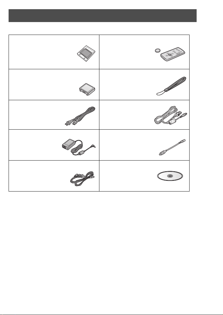
Accessories
Check the accessories before using this unit.
SD Memory Card
(2 GB)
RP-SDQ02G
Battery pack
CGA-S303
AC cable
K2CA2CA00025
AC adaptor
VSK0681
Multi cable
K2KZ9CB00001
Optional Accessory Battery Pack CGA-S303
Wireless remote
control
N2QACC000008
Button-type battery
CR2025
Hand strap
VFC4127
USB cable
VFA0454
Headphone cable
K2KZ99Z00001
CD-ROM
9
VQT0T50
Page 10
Parts identification and handling
2
4
3
5
6
7
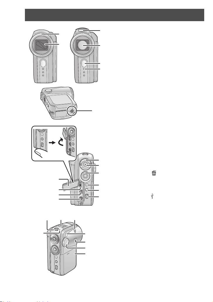
1 Lens hood (P11)
1
14
15
16
17
212019
18
22
23
24
25
2 Lens cover
3 Built-in flash (P54)
4 Lens (LEICA DICOMAR)
5 Remote Control Sensor (P13)
6 Indication lamp (P32)
7 Tripod mount (P11)
8 Zoom lever [W/T] (P36)
Volume lever [rVOLs] (P58)
9 Record button (P33, 50)
10 Cursor button (P22)
≥Press up, down, left or right to select items.
≥Press the button in the center to enter the
8
9
10
11
12
13
selection.
11 Menu button [MENU] (P26)
12 Delete button [ ] (P62)
13 Mode select switch [AUTO/MANUAL/
FOCUS] (P32, 43 to 48)
14 Terminal cover (P67, 70, 80)
15 USB terminal [ ] (P67, 80)
16 Multi-connector [MULTI] (P12, 70)
17 DC input terminal [DC IN 9.3V] (P17)
18 Status indicator (P17 to 19)
19 Power switch [ON/OFF] (P18)
20 Microphone (built-in, stereo)
21 Flash lever [OPENß] (P54)
22 White balance sensor (P47)
23 Speaker (P58)
24 Mode dial (P20)
25 Battery cover (P16)
10
VQT0T50
Page 11
26
29
30
31
32
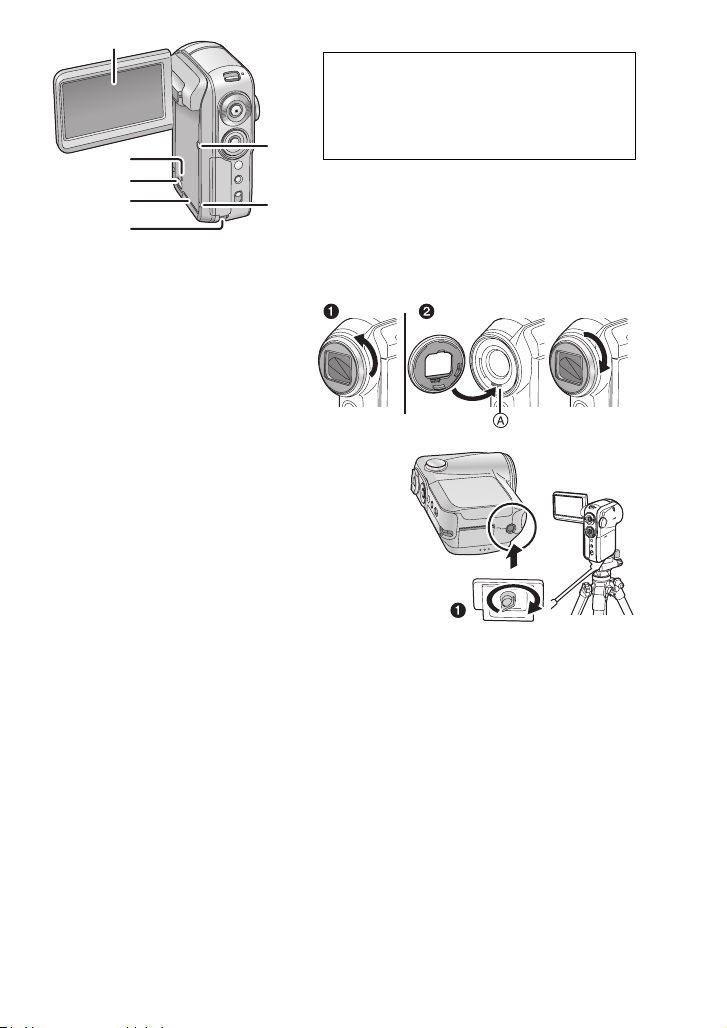
26 LCD monitor (P21, 107)
Due to limitations in LCD production
technology, there may be some tiny bright or
dark spots on the LCD monitor screen.
However, this is not a malfunction and does
not affect the recorded picture.
27
27 Power LCD button [POWER LCD] (P30)
28 Reset button [RESET] (P101)
28
29 Card access lamp [ACCESS] (P15)
30 Card slot open lever (P14)
31 Card slot cover (P14)
32 Strap fixture (P12)
Lens hood
1In order to remove the lens
hood, rotate it
counter-clockwise.
2In order to fit it, put into slot A,
and then rotate it clockwise.
Tripod mount
This is a hole for attaching this unit to a tripod
(optional). (Please carefully read the operating
instructions for how to attach the tripod to the unit.)
This unit does not have a hole for a tripod pin so
attach it to a tripod without a tripod pin. If you try to
forcibly attach this unit to a tripod with a fixed tripod
pin, this unit may get scratched or damaged.
≥ When a tripod is used, you can perform
operations easily using the remote control.
≥ When the tripod is used, the card slot cover and
battery cover cannot be opened. Insert an SD card or the battery before attaching
this unit to the tripod. (P14, 16)
1 Camera base
11
VQT0T50
Page 12
Parts identification and handling (continued)
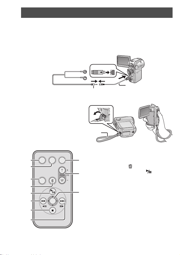
Multi-connector [MULTI]
Only connect the supplied multi cable and supplied headphone cable to this connector
as the sound may not be output correctly if you connect other cords.
∫ Connecting headphones 1 (optional: ‰ 3.5 mm stereo mini plug)
using the headphone cable (supplied) 2
MULTI
Hand strap fixture
We recommend using the hand
strap (supplied) to prevent the unit
from dropping.
Hand strap
1
Remote control
1
TIME
DATE/
OSD
2
3
MENU
4
5
6
ENTER
7
8
12
VQT0T50
START/
STOP
1
1
1 On-screen display button [OSD] (P71)
2 Date/time button [DATE/TIME] (P29)
9
3 Menu button [MENU] (P26)
4 Delete button
10
5 Playback/Pause button [ ]
(P13, 57, 60)
6 Fast-rewind button [:]
(P13, 57, 60)
11
7 Stop button [∫] (P13, 57, 60)
8 Fast-forward button [9]
(P13, 57, 60)
9 Recording start/stop button
[START/STOP]
10 Zoom/volume button [T]/[W]
11 Enter button [ENTER] (P13)
Recording operations, playback operations
¢
and volume adjustment
These buttons work in the same way as the
corresponding buttons on this unit.
2
[] (P63)
¢
¢
¢
¢
¢
¢
Page 13
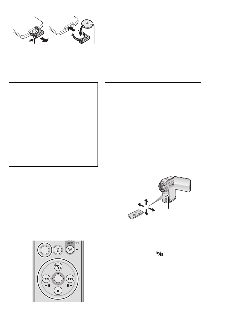
∫ Install a button-type battery (supplied) in the remote control
1) While pressing the stopper 1, pull out
the battery holder.
2) Set the button-type battery with its (i)
mark facing upward 2 and get the
12
battery holder back in place.
∫ About the button-type battery
≥ When the button-type battery runs down, replace it with a new battery (CR2025).
The battery typically lasts about one year; the actual life may be less with heavy use.
≥ Keep the button-type battery out of the reach of children.
Warning
Danger of explosion if battery is
incorrectly replaced.
Replace only with the same or
equivalent type recommended by the
equipment manufacturer. Discard used
batteries according to manufacturer’s
instructions.
Risk of fire, explosion and burns. Do not
recharge, disassemble, heat above
Replace battery with Panasonic PART
NO. CR2025 only. Use of another battery
may present a risk of fire or explosion.
Caution: Battery may explode if
mistreated.
Dispose of used battery promptly. Keep
away from children.
Do not recharge, disassemble or dispose
of in fire.
100 °C (212 °F) or incinerate. Keep the
Button-Type battery out of the reach of
children. Never put Button-Type battery
in mouth. If swallowed, call your doctor.
∫ Remote control usable range
The distance between the remote control and the
unit: Within approx. 5 m (15 feet)
Angle: Approx. 10o up and 15o down, left, and right
1 Remote control sensor
≥ The remote control is intended for indoor
operation. Outdoors or under strong light, this
unit may not operate properly even within the
1
usable ranges.
∫ Operating with remote control (P26)
The menu screen transition is the same as when the buttons on the main unit are used.
1) Press the [MENU] button.
MENU
ENTER
2) Select a menu item.
≥The play/pause button [ ], stop button [∫],
Fast-rewind button [:], Fast-forward
button [9] and [ENTER] button can be
used in place of pressing the cursor button
up, down, left, right and the button in the
center on this unit.
3) Press the [ENTER] button to exit the
menu screen.
13
VQT0T50
Page 14
Inserting/Removing an SD card
Before inserting/removing an SD card, be sure to turn the power [OFF]. (P18)
If the SD card is inserted or removed with the power turned on, this unit may
malfunction or the data recorded on the SD card may be lost.
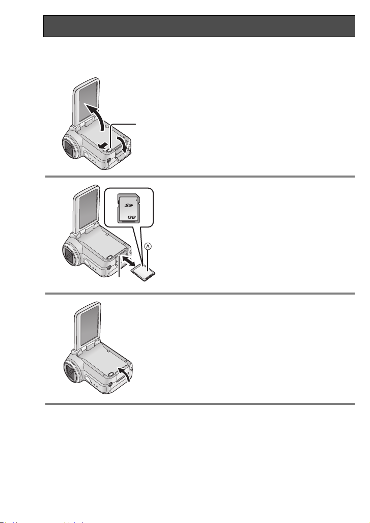
1 Open the LCD monitor and then slide
the card slot open lever 1 to open the
card slot cover.
1
2 Insert/remove the SD card into/from
the card slot 2.
2
2
3 Securely close the card slot cover.
A Label side
≥ When inserting an SD card, face the label side
towards you and press it straight in with one
stroke as far as it goes.
≥ When removing the SD card, open the card
slot cover and press the center of the SD card
and then pull it straight out.
14
VQT0T50
Page 15
∫ About the SD Memory Cards that you can use
SD card capacity
Recording mode
Motion picture
recording mode
8MB, 16MB
Cannot be
used.
32 MB, 64 MB,
128 MB
Cannot be
guaranteed in
operation
¢
256 MB, 512 MB, 1 GB,
(Maximum)
2GB
Refer to page 34.
Still picture
recording mode
¢
The recording may suddenly stop during motion picture recording.
Can be used.
(P35)
∫ About the SD card
≥ Do not touch the terminals on the back of the SD card.
≥ Electrical noise, static electricity, or failure of this unit or the SD card may damage or
erase the data stored on the SD card. We recommend saving important data on a
PC by using the USB cable (supplied) or MotionSD STUDIO. (P73) (When saving
images recorded using this unit to a PC, you must use MotionSD STUDIO. )
≥ When using an SD card on which data has been written many times, the remaining
time left for recording may be reduced. (P35)
∫ About the card access lamp
≥ When this unit accesses the SD card (reading, recording, playback, erasing, etc.),
the access lamp lights up.
≥ If the following operations are performed when the access lamp is lit, then the SD
card or the recorded data may be damaged or this unit may malfunction.
– Opening the card slot cover and inserting or removing the SD card.
– Operating the [ON/OFF] switch or the mode dial.
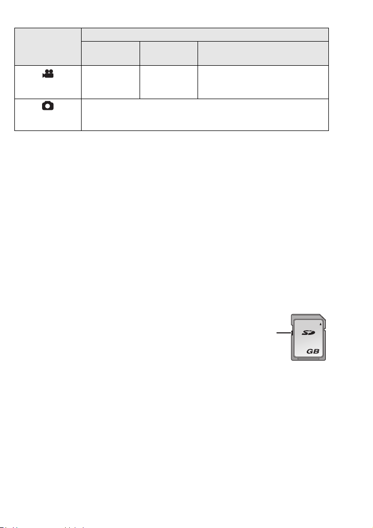
∫ About the write protection switch on the SD Memory Card
≥ The SD Memory Card has a write protection switch 1 on it. If the
switch is moved to [LOCK], you cannot write to the SD card,
delete the data on it or format it. If it is moved back, you can.
1
2
15
VQT0T50
Page 16
Inserting/Removing the Battery
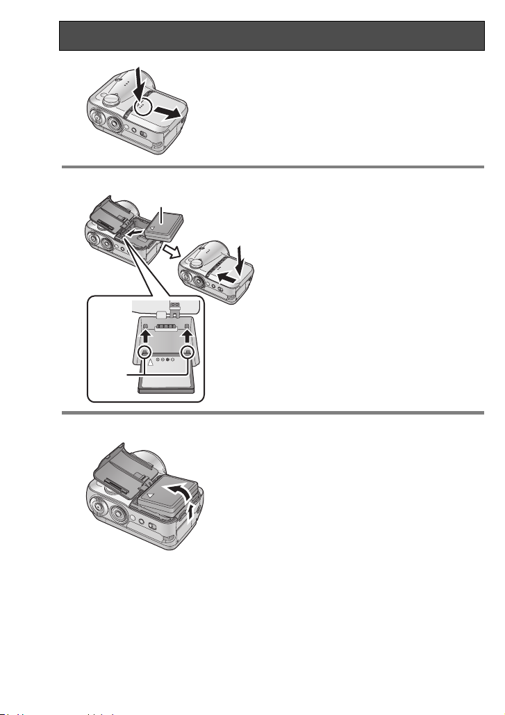
1 Remove the battery cover.
11
22
2 Insert the battery.
2
1
A
B
1 While pushing the battery cover,
2 slide it in the direction of the arrow.
1 Place the battery label side up.
2 Insert the projecting parts of the battery
in the holes on the unit.
3
3 Put the battery cover back in its
original place.
A Label
B Projecting parts
Removing the battery
Remove the battery cover, then
remove the battery.
≥ After removing the battery, put the battery
cover back in its original place.
16
VQT0T50
Page 17
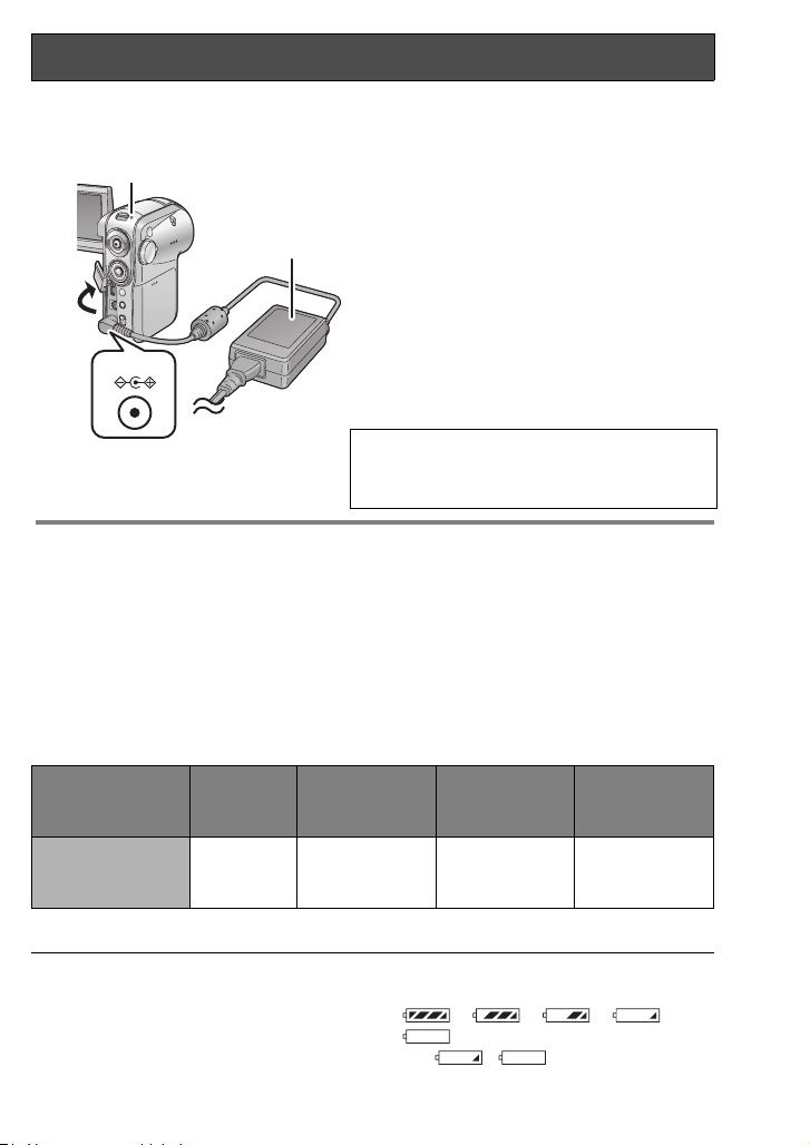
Charging the Battery
When this unit is purchased, the battery is not charged. Charge the battery before using this unit.
¬Set the power switch to [OFF]. (P18)
Connect the AC adaptor (supplied) A
B
A
1
2
DC IN 9.3V
3
∫ Connecting to the AC outlet
If you turn on this unit while charging the battery using the AC adaptor, you can use the
power supplied from the AC outlet to power the unit for use. (While it is in use, the
battery will not be charged.)
∫ Charging time and recordable time
The times shown in the table below show the times at a temperature of 25 oC (77 oF)
and a humidity of 60%. This is just a guide. If the temperature is higher or lower than
the specified value, the charging time will become longer.
≥ The intermittent recordable time refers to recordable time when the recording and
stopping operations are repeated. In reality, it may be shorter than this.
Battery model
number
Supplied battery/
CGA-S303
(optional)
≥ “1h 30 min” indicates 1 hour 30 minutes.
Vol ta ge /
capacity
7.4 V/
760 mAh
to this unit and the AC outlet.
1 Open this unit’s terminal cover.
2 Connect the AC adaptor to this unit’s DC
input terminal [DC IN 9.3V].
3 Connect the AC mains lead to the AC
adaptor, then the AC outlet.
The status indicator B starts blinking in red at
intervals of about 2 seconds to signal that
charging has commenced. Charging is
completed when the lamp goes off.
≥ If the status indicator blinks faster or slower,
refer to page 106.
The
AC Cable
not use it with other devices or use the
Cable
Charging time
Approx.
1h30min
is for use with this unit only. Do
for other devices with this unit.
Maximum
continuously
recordable time
Approx.
1h20min
Intermittent
recordable time
AC
Approx.
45 min
≥
The recordable time will become shorter
when you use this unit with the LCD monitor lit
up by pressing the [POWER LCD] button.
≥
The batteries heat up after use or charging.
The unit and the SD card also heat up during
use. This is not a malfunction.
≥ Along with the reduction of the battery
capacity, the display will change:
####
. If the battery discharges,
then ( ) will flash.
17
VQT0T50
Page 18
Turning the unit on/off
1
How to turn on the power
Set the power switch to [ON].
The status indicator 1 lights red and, in motion
picture recording mode or still picture recording
ON
OFF
ON
OFF
mode (P20), the lens cover opens.
How to turn off the power
Set the power switch to [OFF].
The status indicator goes out and the lens cover
closes.
≥ If the LCD monitor is closed in motion picture
recording mode or still picture recording mode
(P20), the power turns off.
Quick start
If quick start is set and then the LCD monitor is closed while the unit’s power is still on,
the unit will be ready for recording about 1.5 seconds after the LCD monitor is next
opened.
Use the quick start function when stopping recording for a few moments.
≥ The quick start function can be set in the following cases.
– In motion picture recording mode, when the SD card is inside this unit
– In still picture recording mode, when the SD card is inside this unit
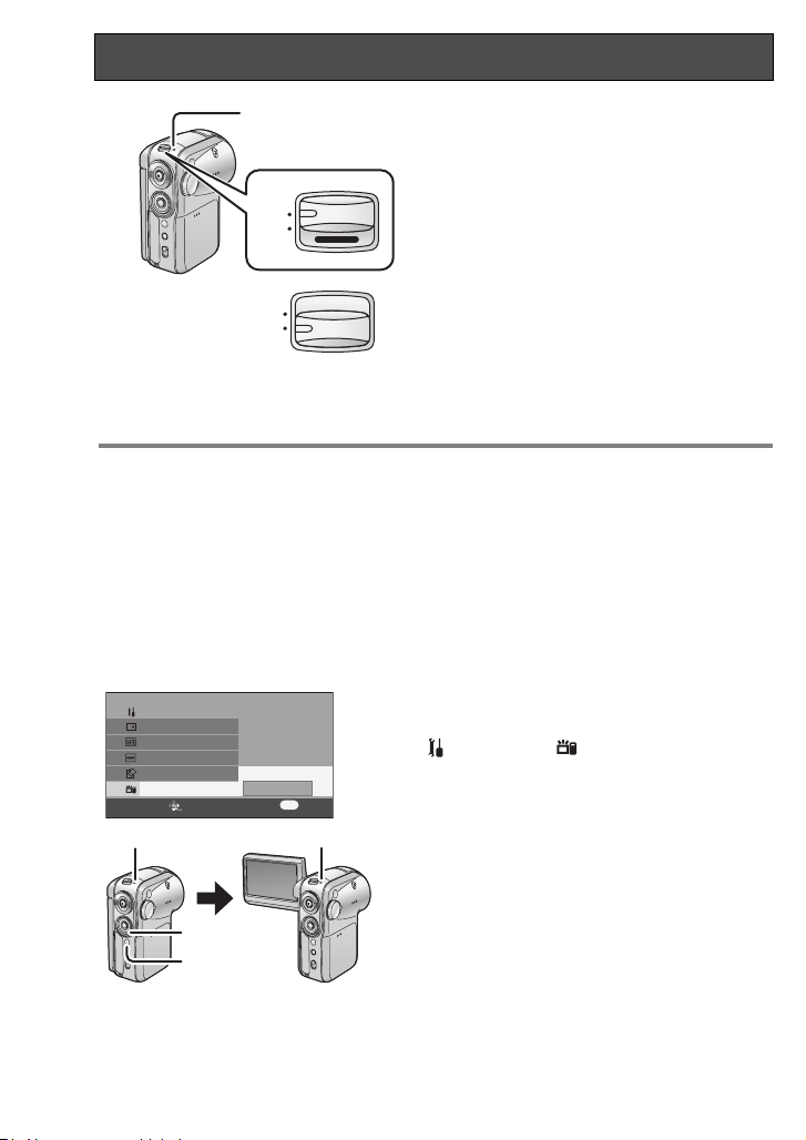
To set quick start function
SETUP
DISPLAY
DATE/TIME
DATE FORMAT
FORMAT CARD
QUICK START
SETUP ENTER
EXIT
OFF
1/3
ON
MENU
12
A
B
Press the menu button B, use the
cursor button A to select
[ SETUP]#[ QUICK START], and
then set the function to [ON]. (P26)
When the LCD monitor is closed, the quick start
standby mode is established.
1 The status indicator lights green.
≥ If quick start is set, the lens cover does not
close.
If the quick start function is set
When the LCD monitor is opened, the unit
goes into recording standby.
2 When the LCD monitor is opened, the status
indicator lights red.
18
VQT0T50
Page 19

To cancel quick start
Press the menu button, use the cursor button to select [ SETUP]#
[ QUICK START]#[OFF]. (P26)
≥ To cancel quick start standby, turn off the
power.
≥ Quick start standby is canceled after
5 minutes have elapsed.
In this case, the unit cannot be
quick-started and it takes longer for it to
start operating.
≥ Quick start standby is canceled if the
mode dial is switched to a mode other
than motion picture recording mode or
still picture recording mode.
≥ Since about half the power of normal
recording is used in quick start standby,
using quick start reduces the recordable
time.
≥ If quick start is not set, it takes longer for
this unit to start operating, but the
amount of power consumed when the
LCD monitor is closed is reduced.
≥ When the LCD monitor is opened in
quick start standby status, the zoom
magnification is set to the 1k
(approximately). This may cause the size
of the image to be different from the size
before standby status was established.
≥ When this unit is quick-started with the
white balance on automatic, it may take
some time until the white balance is
adjusted if the scene being recorded has
a light source different from the scene
last recorded. (When the MagicPix
function is used, however, the white
balance of the scene last recorded is
retained.)
19
VQT0T50
Page 20
Selecting a mode
;
0h00m00s
15:42
DEC 15 2005
R 0h03m
3/24
15:42
DEC 15 2005
R 1
3/24
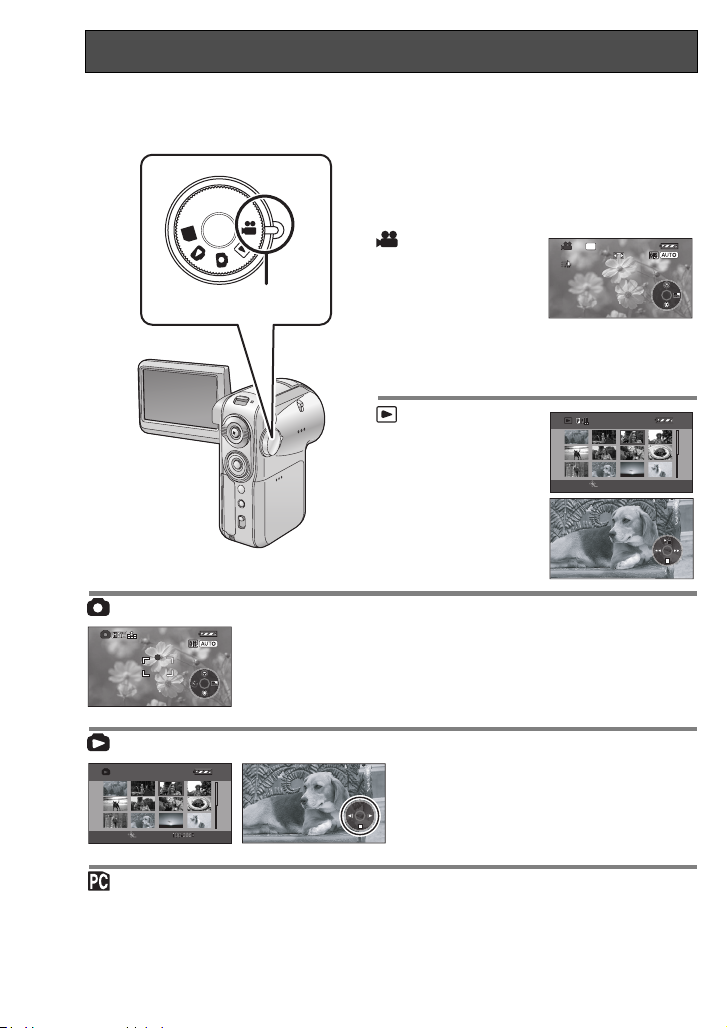
The Mode Dial is used to switch between recording and playback modes.
Rotate the mode dial slowly but surely.
Set the desired mode 1.
Rotate the mode dial, and set the
desired mode pictograph to the
position shown in the illustration.
PC
1
Motion picture
recording mode
R 0h03m
(P33)
Use this to record
motion pictures
15:42
DEC 15 2005
(MPEG2).
The unit can be used as a Web camera when
it is connected to a PC.
SP
0h00m00s
;
VQT0T50
Motion picture
playback mode
(P57)
Use this to play back
motion pictures
SETUP PLAY
recorded with this
unit.
Still picture recording mode (P50)
R 1
15:42
DEC 15 2005
;
Use this to record still pictures (JPEG).
The unit can be used as a Web camera
when it is connected to a PC.
Still picture playback mode (P60)
3/24
SETUP PLAY
Use this to play back still pictures
recorded with this unit.
PC Connection mode (P73)
Use MotionSD STUDIO (This can be installed from the supplied CD-ROM.) to view an
SD card’s pictures on a PC or to import them to a PC.
20
3/24
Page 21
Using the LCD monitor
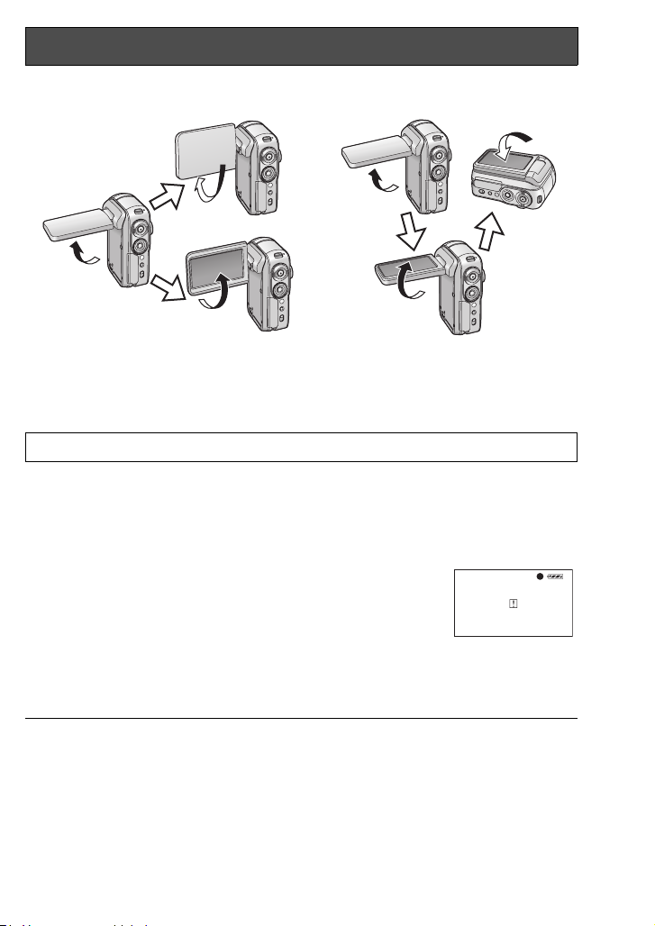
Adjusting the monitor’s angle
AB
90o
1
90o
90o
2
180o
A When recording
1 Face-to-face
2 Normal
B When playing back
Rotating the LCD monitor beyond the angles given above may damage it.
180o
90o
∫ About face-to-face recording
Turning the LCD monitor in direction 1 is convenient for recording shots of yourself
while viewing the monitor or allowing the person or persons whose shots are being
recorded to watch what is being recorded.
≥ When using this unit for face-to-face recording, the left and
right sides of the images appearing on the LCD monitor during
recording are reversed.
Only some screen indications will appear on the LCD monitor.
°
When [
check the warning/alarm indications. (P94)
≥ When using this unit for face-to-face recording, you cannot operate the operation
icons using the One-touch navigation (P22).
] appears, turn the LCD monitor in direction 2, and
≥ The brightness and color level of the LCD
monitor can be adjusted from the menu.
(P29)
≥ If it is forcibly opened or rotated, this unit
may be damaged or fail.
≥ Check that the card slot is closed, and
then close the LCD monitor firmly.
21
VQT0T50
Page 22
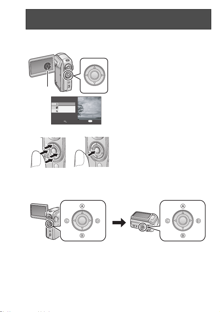
Using the cursor button
One-touch navigation
This unit has a cursor button for selecting recording functions, performing playback
operations, etc. so it is easy to operate this unit with one hand.
Press the cursor button while simultaneously viewing the screen.
Press the cursor button to operate the
operation icons 1 and menu screen
2 appearing on the LCD monitor.
1
2
BASIC
ADVANCE
SETUP
MENU
2
EXIT
Press the cursor button
or right
to select items or files 1, and
up, down, left
then press the button in the center to
enter the selection 2.
≥ Menu screen operations (P26)
≥ File playback selection (P57, 60)
SETUP ENTER
Basic cursor button operations
1
In viewer style
When the LCD monitor is put back into place with its back facing out, the up, down, left
and right positions of the cursor button change as shown in the illustration.
22
VQT0T50
A Up
B Down
C Left
D Right
Page 23
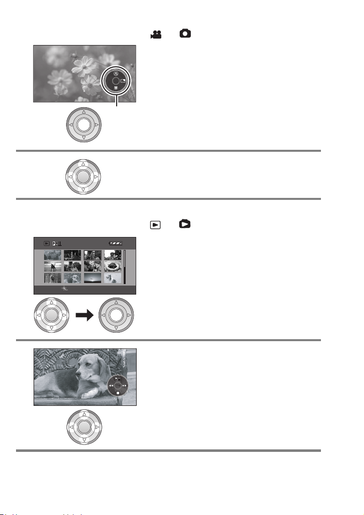
Using the recording function
3/24
¬When the mode dial is at the or position
1 Press the button in the center.
1 An operation icon appears on the LCD
monitor.
While an operation icon is displayed, a blue
border appears around the outside of the button
in the centre of the cursor button.
1
≥ Each time the button in the center is pressed,
the indication changes.
2 Press the cursor button up, down, left
or right to make a selection.
Playback
¬When the mode dial is at the or position
1 Press the cursor button up, down, left
SETUP PLAY
3/24
or right to select the file, and then
press the button in the center.
All the scenes are displayed and an operation
icon automatically appears.
2 Press the cursor button up, down, left
or right to proceed with the operation.
23
VQT0T50
Page 24
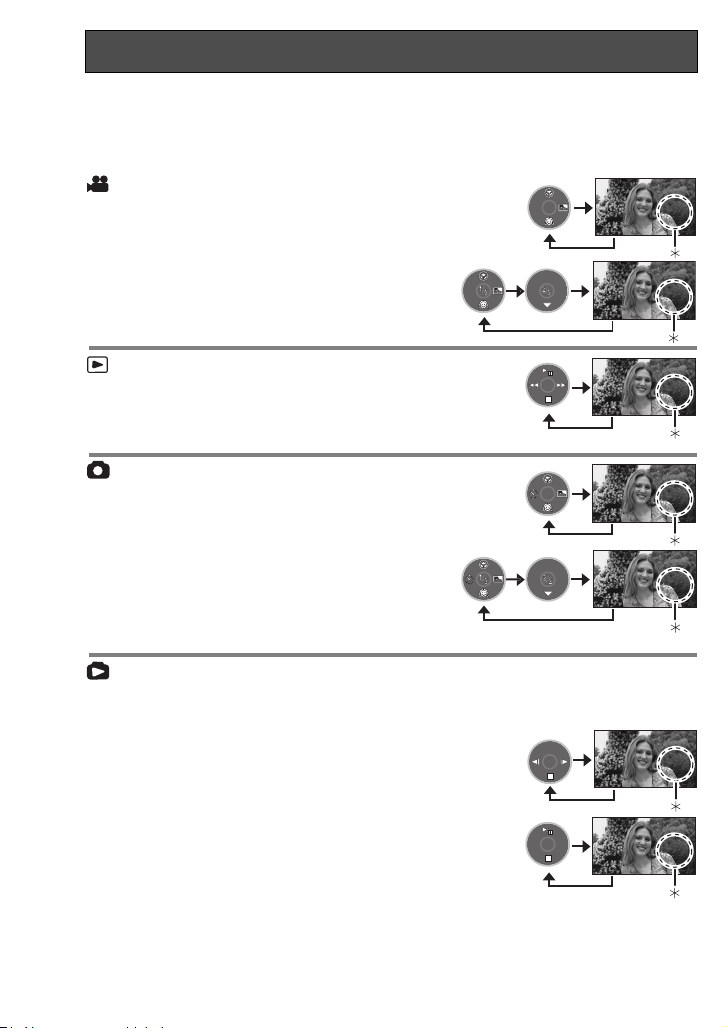
Using the cursor button (continued)
About the operation icons which are displayed
Each time the button in the center is pressed while an operation icon is displayed, the
indication changes as shown below.
¢ The operation icon is off.
Motion picture recording mode
([AUTO/MANUAL/FOCUS]
switch is set to [AUTO])
([AUTO/MANUAL/FOCUS] switch is set
to [MANUAL])
Motion picture playback mode
≥ The indication can also be changed during
playback.
Still picture recording mode
([AUTO/MANUAL/FOCUS]
switch is set to [AUTO])
([AUTO/MANUAL/FOCUS]
switch is set to [MANUAL])
Still picture playback mode
≥ The indication can also be changed during
playback.
(When [PICTURE] is selected)
(When [SLIDE SHOW] is selected)
24
VQT0T50
Page 25
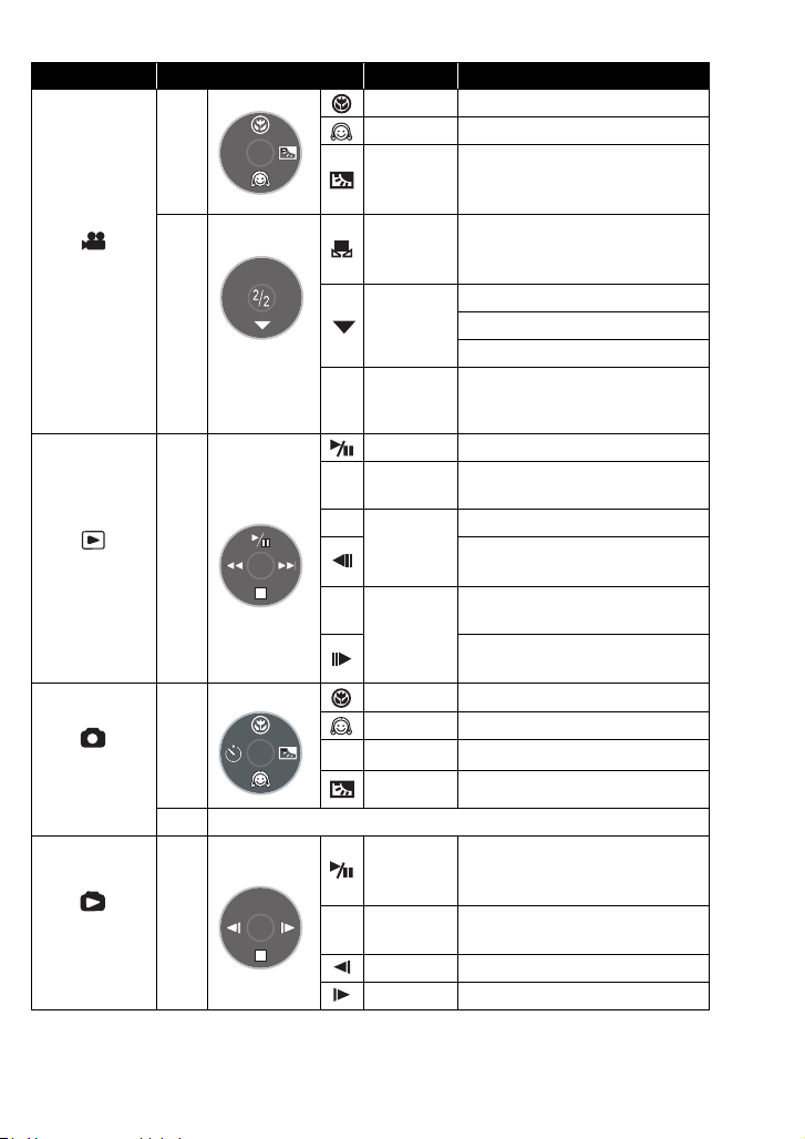
List of operation icons for each mode
Mode Icon Direction Function
3 Tele-macro (P37)
4 Soft skin mode (P38)
1 Backlight compensation (P39)
Manual adjustment mode (P47)
(Only in manual white balance
3
adjustment)
White balance (P46)
4
Shutter speed (P48)
Iris or gain value (P48)
21
White balance mode selection,
manual adjustments (P45, 46, 48)
3 Playback/pause (P57)
Stop playback and show
thumbnails (P57)
Rewind, skip (during playback) (P57)
2
Reverse slow/frame playback
(during pause) (P58)
Fast forward, skip (during
playback) (P57)
1
Forward slow/frame playback
(during pause) (P58)
3 Tele-macro (P37)
4 Soft skin mode (P38)
2 Self timer (P56)
1 Backlight compensation (P39)
Slide show start/pause (P60)
3
(Only when [SLIDE SHOW] has been
selected.)
Stop playback and show
thumbnails (P60)
2
Playback previous picture (P60)
1 Playback next picture (P60)
Motion picture
recording mode
Motion picture
playback mode
Still picture
recording mode
Still picture
playback mode
—
(1/2)
(2/2)
(Only in
[MANUAL] )
—
r
s
∫4
:
9
—
(1/2)
(2/2)
Same as motion picture recording mode (2/2)
—
Ø
∫ 4
25
VQT0T50
Page 26
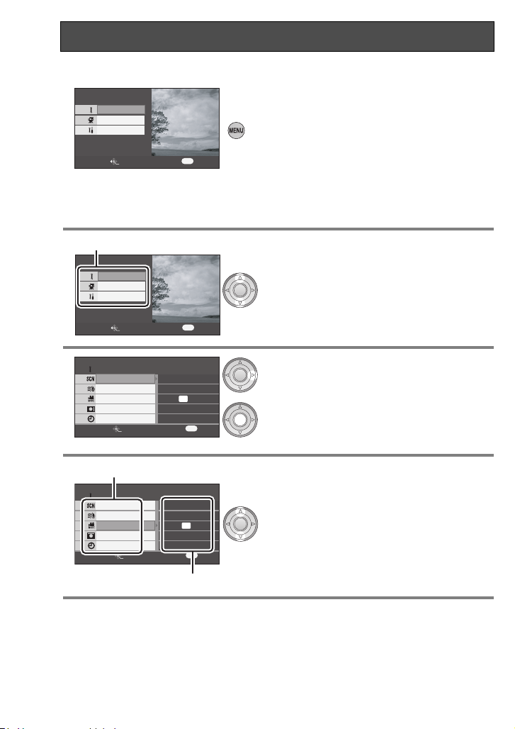
Using the menu screen
Refer to the “Menu list” (P89) for information about the menus.
1 Press the [MENU] button.
BASIC
ADVANCE
SETUP
MENU
SETUP ENTER
2 Press the cursor button up or down in
1
BASIC
ADVANCE
SETUP
SETUP ENTER
3 Press the cursor button right or press
BASIC
SCENE MODE
WIND CUT
REC MODE
WIDE
CLOCK SET
SETUP ENTER
EXIT
EXIT
EXIT
OFF
ON
ON
NO
MENU
SP
MENU
The menu setting screen is displayed.
(The menu displayed differs depending on the
position of the mode dial.)
≥ Do not switch the mode dial when the menu is
displayed.
≥ The menu screen is not displayed during
recording and playback. You also cannot
record or play back while the menu screen is
displayed.
order to select the desired top menu
1.
the button in the center.
4 Press the cursor button up or down in
1
BASIC
SCENE MODE
WIND CUT
REC MODE
WIDE
CLOCK SET
SETUP ENTER
EXIT
OFF
order to select the submenu item.
1 Submenu
ON
SP
ON
NO
MENU
2 Current settings on menus
2
26
VQT0T50
Page 27
5 Press the cursor button right or press
BASIC
SCENE MODE
WIND CUT
REC MODE
WIDE
CLOCK SET
SETUP ENTER
6 Press the cursor button up or down in
BASIC
SCENE MODE
WIND CUT
REC MODE
WIDE
CLOCK SET
SETUP ENTER
EXIT
EXIT
XP
SP
LP
MENU
XP
SP
LP
MENU
the button in the center.
order to select the desired item.
7 Press the button in the center to enter
or
the selection or press the cursor
button left to get back to the previous
screen.
To exit the menu screen
Press the [MENU] button.
To get back to the previous screen
Press the cursor button left.
≥ If you change the settings for [WIDE] (P40), [PICTURE SIZE] (P52) or [TVASPECT]
(P71), the screen size changes. (If you change [PICTURE SIZE] to or from [HDTV], the
size changes.)
27
VQT0T50
Page 28
Setting date and time
If the screen shows the incorrect date/time, then adjust it.
¬Rotate the mode dial to select or .
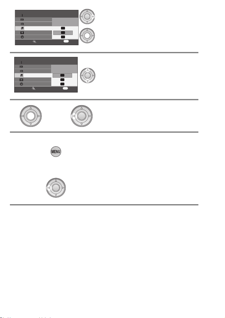
1 Press the menu button, then use the
BASIC
SCENE MODE
WIND CUT
REC MODE
ワイド
WIDE
CLOCK SET
SETUP ENTER
EXIT
YES
NO
cursor button to select
[BASIC]#[ CLOCK SET]#
[YES]. (P26)
MENU
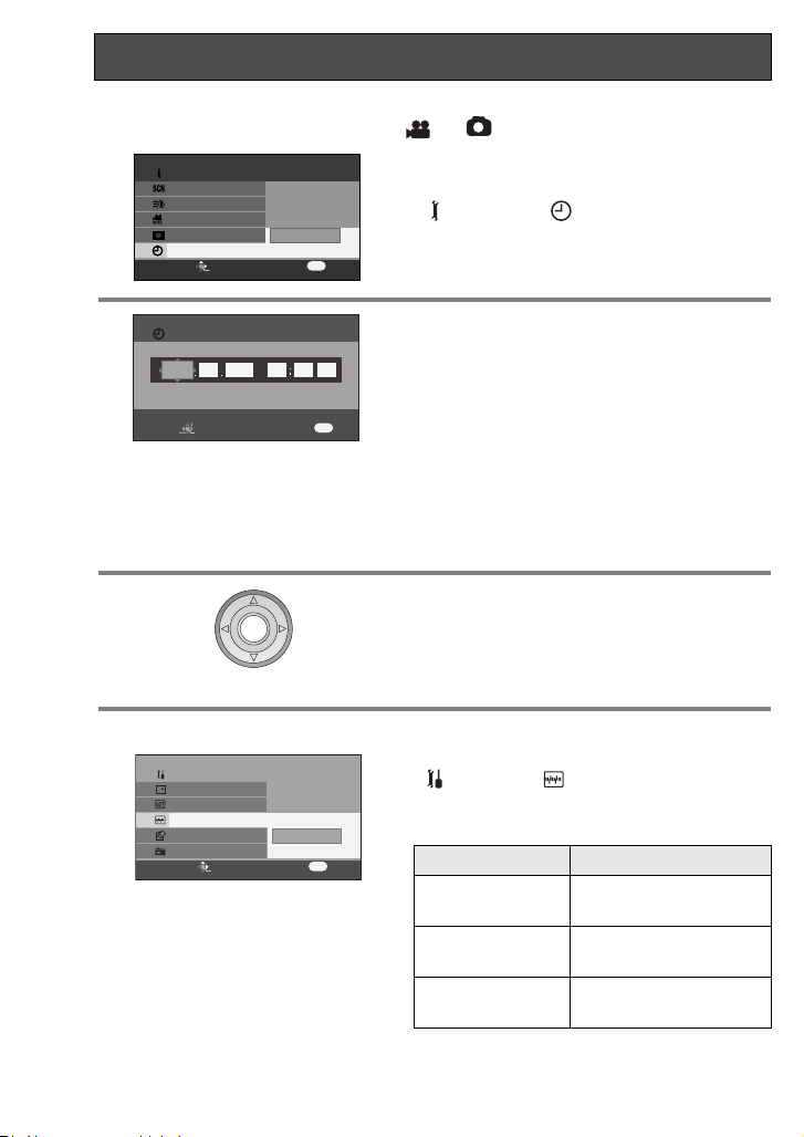
2 Press the cursor button
CLOCK SET
2005
DEC 15 03 42 PM
select the item (year/month/day/
hours/minutes) to be set. Then, press
the cursor button
SETUP
SET ENTER
EXIT
MENU
the desired value.
≥ The year will change as follows:
left or right
up or down
to
to set
2000, 2001, ..., 2099, 2000, ...
≥ When [Y/M/D] or [D/M/Y] has been set for
[DATE FORMAT], the 24-hour system is used
to display the time. When [M/D/Y] has been
set, the 12-hour system is used.
3 Press the button in the center to enter
the selection.
≥ After pressing the Menu button to finish the
setting, check the date and time display.
≥ The clock function starts at [00] seconds.
Changing the display style
SETUP
DISPLAY
DATE/TIME
DATE FORMAT
FORMAT CARD
QUICK START
SETUP ENTER
EXIT
Y/M/D
M/D/Y
D/M/Y
1/3
MENU
Press the menu button, select
[SETUP]#[ DATE FORMAT], then
use the cursor button to select the desired
display style. (P26)
Display style Screen display
Y/M/D
M/D/Y
D/M/Y
15:42
2005.12.15
3:42 PM
DEC 15 2005
15:42
15.12.2005
28
VQT0T50
Page 29
Changing the date and time display style
SETUP
DISPLAY
DATE/TIME
DATE FORMAT
FORMAT CARD
QUICK START
SETUP ENTER
EXIT
OFF
D/T
DATE
1/3
MENU
Press the menu button, select
[SETUP]#[ DATE/TIME], then use
the cursor button to select the desired
display style. (P26)
≥ The date and time display can also be
changed by pressing the [DATE/TIME] button
on the remote control.
[DATE]
[D/T]
[OFF]
3:42 PM
DEC 15 2005
DEC 15 2005
∫ About date/time
≥ The date and time function are driven by a built-in lithium battery.
Make sure to check the time before recording because the built-in clock is not very accurate.
≥
≥ If [0] or [– –] is indicated when this unit is turned on, then the built-in lithium battery
runs down. After charging the battery using the steps below, set the clock.
∫ Charging the built-in battery for the date
≥ Connect the AC adaptor to this unit or place the battery on this unit, and the built-in
lithium battery will be recharged. Leave this unit as is for approx. 24 hours, and the
battery will save the date and time for approx. 6 months. (Even if the [ON/OFF]
switch is set to [OFF], the battery is still being recharged.)
Adjusting LCD monitor
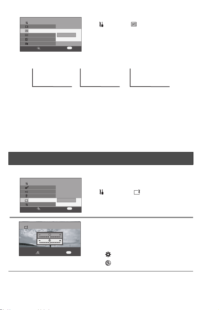
Adjusting the brightness and color level of the LCD monitor
1 Press the menu button, then use the
2 Press the cursor button
SETUP
POWER SAVE
BEEP SOUND
LCD AI
LCD SET
INITIAL SET
SETUP ENTER
LCD SET
SET
SETUP ENTER
EXIT
EXIT
YES
NO
MENU
MENU
2/3
cursor button to set
[SETUP]#[ LCD SET]#[YES].
(P26)
up or down
to
select the item to be adjusted. Then,
press the cursor button left or right to
make the adjustment.
The bar display moves.
– : Brightness of the LCD monitor
– : Color level of the LCD monitor
≥ These settings will not affect the images actually recorded.
29
VQT0T50
Page 30
Adjusting LCD monitor (continued)
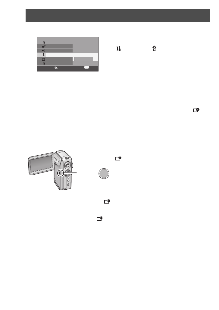
Changing the picture quality on the LCD monitor (LCD AI)
Press the menu button, then use the
SETUP
POWER SAVE
BEEP SOUND
LCD AI
LCD SET
INITIAL SET
SETUP ENTER
NORMAL
DYNAMIC
MENU
EXIT
2/3
cursor button to select
[ SETUP]#[ LCD AI]#
[DYNAMIC] or [NORMAL]. (P26)
– [DYNAMIC]:
The image on the LCD monitor becomes
clear and vivid.
– [NORMAL]:
Switches to the standard picture quality.
≥ When [DYNAMIC] is set, the LCD
monitor is set to the
color level and
brightness optimally suited for the
particular scenes to be recorded. Crisp
and bright images will be displayed.
≥ The effect will vary depending on the
scene recorded.
≥ This function is automatically set to
[DYNAMIC] when the brightness of the
LCD monitor is increased (when [ ] is
displayed) and cannot be set to
[NORMAL] independently.
≥ This will not affect the images to be
recorded.
In order to increase the brightness of the entire LCD monitor
Press the [POWER LCD] button.
[ ] appears on the LCD monitor.
≥ If the [POWER LCD] button is pressed, the
POWER LCD
≥ When the button is pressed again, [ ] goes off, and the original brightness is restored
to the LCD monitor.
≥ This will not affect the images to be recorded.
≥ When the AC adaptor is used, [ ] appears automatically and the monitor becomes
brighter when the power is turned on.
entire LCD monitor will become approx. twice
as bright as the normal.
≥ LCD stands for Liquid Crystal Display, and in
this context refers to the LCD monitor.
30
VQT0T50
Page 31

Recording
3:42 PM
DEC 15 2005
3:42 PM
DEC 15 2005
Check before recording
First, format the SD card if one which has been used on another device is going to be used
for the first time on this unit. (P65) When the SD card is formatted, all of the recorded data
(files) is deleted. Once the data is deleted, it cannot be restored. Copy valuable data onto a
PC or other device before proceeding with the formatting. When copying images recorded
using this unit to a PC, you must use MotionSD STUDIO. (P73)
Depending on the TV connected,
the sides of the images (the part
outside the dotted line) being
played may not appear. We
recommend widening the recording
range of the objects you want to
record beforehand.
116:9 screen
24:3 screen
This unit is compatible with wide-screen TVs (16:9) and set to wide mode at the time of
purchase. To watch images on normal TVs (4:3), change the wide mode setting before
recording (P40) or when playing back the images on the TV screen (P71).
12
3:42 PM
DEC 15 2005
3:42 PM
DEC 15 2005
16:9 4:3
∫ Basic camera holding
≥ Open the LCD monitor.
Recording cannot start when the LCD monitor
1
2
is closed. However, even if the LCD monitor is
closed during recording, the power does not
turn off until recording is ended.
3
≥ The angle of the LCD monitor can be adjusted
to suit what you want to record.
≥ We recommend attaching the hand strap 4
(supplied) to prevent the camera from dropping.
≥ Do not cover the White balance sensor 3 with
4
your fingers, etc.
≥ Do not cover the lens, the front of the flash 1 or the built-in stereo microphone 2
with your fingers.
31
VQT0T50
Page 32

Check before recording (continued)
∫ About the indication lamp 1
The indication lamp flashes when signals from the remote control
are sensed and during self-timer operation.
When [ REC LAMP] in [ ADVANCE] is set to [ON], the
lamp lights during recording. You can therefore confirm recording
when this unit is attached to a tripod or when using the remote
control.
∫ About the auto mode
≥ Set the [AUTO/MANUAL/FOCUS] switch to [AUTO],
and color balance (white balance) and focusing will
be adjusted automatically.
(The [ ] indication appears on the screen.)
AUTO
– Automatic white balance:P103
Auto focus: P104
–
AUTO
MANUAL
FOCUS
32
VQT0T50
Page 33

Motion picture recording (MPEG2 motion pictures)
R 0h02m
0h00m10s
Record motion pictures onto an SD card.
1 Rotate the mode dial to select .
The lens cover now opens automatically.
PC
2 Press the record button to start
recording.
Ending the recording
Press the record button again.
1 [¥] and [;] are red during recording.
2 Do not move this unit until [;] is green.
∫ About the screen indications in the motion picture recording mode
1 Recording time elapsed
R 0h02m
R 0h02m
SP
0h00m10s
0h00m10s
1
2 Quality of motion picture
2
3 Remaining time left for recording
(When the remaining time on the SD card
3
is less than 1 minute, [R 0h00m] flashes
red.)
33
VQT0T50
Page 34

Motion picture recording (MPEG2 motion pictures) (continued)
Changing the recording mode of the motion picture
1
BASIC
SCENE MODE
WIND CUT
REC MODE
WIDE
CLOCK SET
SETUP ENTER
EXIT
XP
SP
LP
MENU
∫ About the kinds of SD cards that can be used
We recommend using the following SD Memory Cards made by Panasonic for motion
picture recording.
SD card memory
256 MB — RP-SDH256 —
512 MB RP-SDK512 RP-SDH512¢ —
1GB RP-SDK01G RP-SDH01G¢ RP-SDQ01G
2GB RP-SDK02G —
¢ No longer made.
Operation in motion picture recording is not guaranteed with an SD card memory from 32 MB to
≥
2 GB except the cards above. (The recording may suddenly stop during motion picture recording.)
Please confirm the latest information about SD cards that can be used for motion
picture recording on the following website.
http://panasonic.co.jp/pavc/global/cs/e_cam
(This website is in English only.)
Approximate recording times of motion pictures per SD card made by Panasonic
SD card memory
256 MB Approx. 3 min Approx. 6 min Approx. 12 min
512 MB Approx. 6 min Approx. 12 min Approx. 25 min
1GB Approx. 12 min Approx. 25 min Approx. 50 min
2GB Approx. 25 min Approx. 50 min Approx. 1 h 40 min
≥ “1h 40 min” indicates 1 hour 40 minutes.
This unit records in VBR. VBR is an abbreviation for Variable Bit Rate. VBR recording
automatically varies the bit rate (amount of data in a fixed time) depending on the
subject being recorded. This means if a subject with sharp movements is recorded, the
recording time per SD card is reduced.
34
VQT0T50
Pro High Speed
SD Memory Card
XP
Press the menu button, then use the
cursor button to select the desired
recording mode by selecting
[BASIC]#[ REC MODE]. (P26)
– :
XP
Motion pictures can be recorded with the
highest picture quality.
–:
SP
Motion pictures can be recorded with normal
picture quality.
–:
LP
Motion pictures can be recorded for longer.
Super High Speed
SD Memory Card
SD Memory Card
Supplied SD card
SP LP
High Speed
/
RP-SDQ02G
Page 35

∫ When recording stops suddenly during motion picture recording
When using an SD card on which data has been written many times and the data
writing speed has reduced, the recording may suddenly stop during motion picture
recording. At this time, the following message will appear:
REC STOPPED.
NOW WRITING.
CARD MAY NOT BE
SUITABLE.
CHECK CARD.
When using an SD card (P34) that can be used for motion picture recording
When this kind of message appears, it is recommended that you format the SD card
being used. (P65) When an SD card is formatted, all the data recorded on it will be
deleted so copy valuable data to the PC prior to formatting. (P80) (When copying data
recorded using this unit, you must use MotionSD STUDIO. (P73))
When using any other card
When motion pictures are to be recorded, use a Panasonic SD card or another SD card
which can be used to record motion pictures. (P34)
≥ Recordable time using the battery
(P17)
≥ 8 MB and 16 MB SD cards cannot be
used for motion picture recording.
≥ If the write protection switch on the SD
card is set to [LOCK], it cannot be
used for recording. (P15)
≥ Even if there is available memory for
recording on the SD card, it may not be
possible to record.
≥ The sound is recorded in stereo.
≥ The recorded scenes are recorded on
the SD card as one motion picture scene.
≥ When recording is resumed after it was
stopped, the scenes will be saved in a
different scene.
≥ When recording motion pictures, do not
remove the battery or disconnect the AC
adaptor. Also do not remove the SD card
while the [ACCESS] lamp is lit. If you do
either of the above, a restore motion
picture scene message is displayed
when the SD card is next inserted or the
power is turned back on. Be sure to
restore the motion picture scene. (P96)
≥ Mosaic-pattern noise may appear on a
playback image in the following cases.
– When there is a complicated pattern in
the background
– When the unit is moved too much or too
fast
– When a subject with sharp movements
has been recorded
(Particularly if [ REC MODE] was set
to [ ] during recording.)
LP
35
VQT0T50
Page 36

Zoom in/out function
This is for moving the zoom lever to adjust the magnification.
You can make people and objects appear closer and landscapes can be recorded in
wide angle. You can zoom in up to 10k optically.
¬Rotate the mode dial to select or .
1 Move the zoom lever.
TW
T
W
r
s
V
L
O
– T side: To bring distant people or objects
appear closer for recording
(zoom in)
– W side: To make sights appear more distant
for recording (zoom out)
1t W T1t WT
5t5t W TWT
1010t10t W TWT
≥ When zooming in and taking a picture
while holding this unit by hand, we
recommend using the image stabilizer
function. (P41)
≥ When distant subjects are brought closer,
they are focused at about 1 m (3.3 feet)
or more.
≥ When the zoom magnification is 1k, this
unit can focus on a subject approx. 4 cm
(1.6 inch) distant from the lens. (Macro
function)
≥ The zoom speed varies depending on the
range over which the zoom lever is
moved.
≥ When the zoom speed is high, the
subject may not be focused easily.
This brings distant subjects even closer for recording
(digital zoom)
If the zoom magnification exceeds 10k, then the digital zoom function will be activated.
The maximum magnification provided by the digital zoom can be switched.
¬Rotate the mode dial to select .
ADVANCE
D.ZOOM
O.I.S.
MAGICPIX
REC LAMP
ZOOM MIC
SETUP ENTER
EXIT
OFF
700x
25x
MENU
≥ The larger the digital zoom magnification, the more the image quality is degraded.
≥ This function cannot be used in still picture recording mode.
Press the menu button, use the cursor
button to select [ ADVANCE]>
[ D.ZOOM], then set the desired
magnification. (P26)
– OFF: Optical zoom only (Up to 10k)
–[25k]: Up to 25k
–[700k]: Up to 700k
36
VQT0T50
Page 37

∫ To use the zoom microphone function
Interlocked with the zooming operation, the microphone will collect sounds clearly far
away with the tele-shot or those in the vicinity with the wide-angle shot.
¬Rotate the mode dial to select .
ADVANCE
D.ZOOM
O.I.S.
MAGICPIX
REC LAMP
ZOOM MIC
SETUP ENTER
EXIT
OFF
ON
MENU
Press the menu button, then use the
cursor button to select
[ ADVANCE]>[ ZOOM MIC]>[ON].
(P26)
Tele-macro function
This is for
By focusing only on the subject and blurring the background, the image can be
impressive. This unit can focus on the subject at a distance of approx. 50 cm (20 inch).
¬
Rotate the mode dial to select or .
1 Press the button in the center of the
bringing only what you want to record into focus to take close-ups.
cursor button to display the icon
shown in the illustration.
2 Press the cursor button
up,
select the [ ] tele-macro icon.
≥ If the magnification is 10k or less, then it is
automatically set to 10k.
[] icon flashes orange, then lights
≥ The
white.
To cancel the tele-macro function
Select the [ ] icon again.
≥ If a sharper focus cannot be achieved, adjust the focus manually. (P45)
≥ In the following cases, the tele-macro function is canceled automatically.
– The zoom magnification becomes lower than 10k.
– The power is turned off or the mode dial is set to a mode other than motion picture
recording mode or still picture recording mode.
then
37
VQT0T50
Page 38

Soft skin mode
This makes skin colors appear softer for a more attractive
appearance.
This is more effective if you record the bust image of a person.
¬
Rotate the mode dial to select or .
1 Press the button in the center of the
cursor button to display the icon
shown in the illustration.
2 Press the cursor button
down,
then
select the [ ] soft skin icon.
≥ The [] icon flashes orange, then lights
white.
To cancel the soft skin mode
Select the [ ] icon again.
≥ If the background or anything else in the scene has colors similar to the skin color, they
will also be smoothed.
≥ If the brightness is insufficient, the effect may not be clear.
38
VQT0T50
Page 39

Backlight compensation function
This is for protecting a backlit subject from being darkened.
Use this function when the light is emanating from behind the subject and the subject
appears dark.
¬Rotate the mode dial to select or .
1 Press the button in the center of the
cursor button to display the icon
shown in the illustration.
2 Press the cursor button
select the [
ª] backlight
right,
compensation icon.
≥ The [ª] icon flashes orange, then lights
white.
≥ The image on the screen will become brighter.
To return to normal recording
Select the [ª] icon again.
≥ In the following case, the backlight compensation is canceled automatically.
– The power is turned off or the mode dial is set to a mode other than motion picture
recording mode or still picture recording mode.
then
39
VQT0T50
Page 40

Wind noise reduction function
This is for
¬Rotate the mode dial to select .
To cancel the wind noise reduction function
Press the menu button, then use the cursor button to select
[ BASIC]>[ WIND CUT]>[OFF]. (P26)
≥ This function’s default setting is [ON].
≥ Reduces the wind noise depending on the wind strength. (If this function is activated in
strong winds, the stereo effect may be reduced. When the wind weakens, the stereo
effect will be restored.)
reducing the wind noise coming into the microphone when recording.
BASIC
SCENE MODE
WIND CUT
REC MODE
WIDE
CLOCK SET
SETUP ENTER
EXIT
OFF
ON
MENU
Press the menu button, then use the
cursor button to select
[BASIC]>[ WIND CUT]>[ON].
(P26)
Wide mode
This is for
This allows you to record images compatible with wide-screen TVs (16:9) and regular TVs (4:3).
∫ Recording images with a 16:9 aspect ratio
¬Rotate the mode dial to select .
selecting the screen’s aspect ratio when recording motion pictures.
BASIC
SCENE MODE
WIND CUT
REC MODE
WIDE
CLOCK SET
SETUP ENTER
EXIT
OFF
ON
MENU
Press the menu button, then use the
cursor button to select
[BASIC]>[WIDE]>[ON]. (P26)
∫ Recording images with a 4:3 aspect ratio
¬Rotate the mode dial to select .
BASIC
SCENE MODE
WIND CUT
REC MODE
WIDE
CLOCK SET
SETUP ENTER
OFF
ON
EXIT
MENU
40
VQT0T50
Press the menu button, then use the
cursor button to select
[BASIC]>[WIDE]>[OFF].
(P26)
Page 41

Image stabilizer function
This is for reducing image shakes during recording.
Reduces the image shaking due to hand movement when recording.
¬Rotate the mode dial to select or .
ADVANCE
D.ZOOM
O.I.S.
MAGICPIX
REC LAMP
ZOOM MIC
SETUP ENTER
EXIT
OFF
ON
MENU
To cancel the image stabilizer function
Press the menu button, then use the cursor button to select
[ ADVANCE]>[ O.I.S.]>[OFF]. (P26)
Press the menu button, then use the
cursor button to select
[ ADVANCE]>[ O.I.S.]>[ON].
(P26)
≥ In still picture recording mode, pressing
the record button halfway increases the
effect of the image stabilizer function.
(MEGA OIS)
≥ When a tripod is used, we recommend
that you turn the image stabilizer off.
≥ It may not be possible to compensate for
image shake when the unit is shaken
greatly or the person recording is chasing
a fast-moving subject to record it.
≥ In the following case, the image stabilizer
function may not work effectively.
– When the digital zoom is used
41
VQT0T50
Page 42

MagicPix functions
This allows recording in dark locations.
This function allows you to record color subjects in dark locations to stand out against
the background.
Attach this unit to a tripod, and you can record images free from vibration.
≥ Recorded scene is seen as if frames were missed.
¬Rotate the mode dial to select .
ADVANCE
D.ZOOM
O.I.S.
MAGICPIX
REC LAMP
ZOOM MIC
SETUP ENTER
OFF
EXIT
ON
MENU
To cancel the MagicPix function
Press the menu button, then use the cursor button to select
[ ADVANCE]>[MAGICPIX]>[OFF]. (P26)
Press the menu button, then use the
cursor button to select
[ ADVANCE]>[MAGICPIX]>
[ON]. (P26)
After exiting the menu screen, the unit is in
manual focus mode. Press the cursor button left
or right to bring the subject into focus manually.
(P45)
In the following cases, press the button in the
center of the cursor button twice to display the
manual focus indication and then focus the
subject.
≥ If MagicPix is set to [ON] when it has
already been set to [ON].
≥ If the mode is changed when MagicPix is
set to [ON].
42
VQT0T50
≥ If set in a bright place, the screen may become whitish for a while.
≥ The MagicPix function makes the signal charging time of CCD up to approximately 30k
longer than usual, so that dark scenes invisible to the naked eye can be recorded
brightly. For this reason, bright dots that are usually invisible may be seen, but this is not
a malfunction.
≥ If you turn off the power, the MagicPix function is canceled.
Page 43

Scene mode
This is for recording in various situations.
When you record images in different situations, this mode automatically sets optimum
shutter speeds and apertures.
¬Rotate the mode dial to select or .
1 Set the [AUTO/MANUAL/FOCUS]
AUTO
MANUAL
FOCUS
switch to [MANUAL].
2 Press the menu button, use the
BASIC
SCENE MODE
WIND CUT
REC MODE
WIDE
CLOCK SET
SETUP ENTER
EXIT
OFF
cursor button to select
[BASIC]>[ SCENE MODE],
then select the desired mode. (P26)
MENU
Indication Mode Recording conditions
5
Sports
Portrait
To record sports scenes or scenes where there are
quick motions
To make persons stand out against the background
Low light To make the scene lighter at dusk or other dark times
Spotlight
Surf & snow
To make the subject under a spotlight look more
attractive
To record images at dazzling places such as ski slopes
and beaches
To cancel the scene mode function
Press the menu button, then use the cursor button to select
[BASIC]>[ SCENE MODE]>[OFF]. (P26)
≥ You can also cancel the scene mode function by setting the [AUTO/MANUAL/
FOCUS] switch to [AUTO].
43
VQT0T50
Page 44

Scene mode (continued)
Sports mode
≥ For slow-motion playback or playback
pause of recorded scenes, this mode
prevents camera shakes.
≥ During normal playback, the scene
movement may not look smooth.
≥ Avoid recording under fluorescent light,
mercury light or sodium light because the
color and brightness of the playback
scene may change.
≥ If you record a subject illuminated with
strong light or a highly reflective subject,
vertical lines of light may appear.
≥ If the brightness is insufficient, the sports
mode does not function. The [5]
indication flashes.
≥ If this mode is used indoors, the screen
may flicker.
Portrait mode
≥ If this mode is used indoors, the screen
may flicker. If this happens, change the
scene mode setting to [OFF].
Low light mode
≥ Extremely dark scenes may not be able
to be recorded finely.
Spotlight mode
≥ If the recording subject is extremely
bright, the recorded scene may become
whitish and the periphery of the recorded
scene extremely dark.
Surf & snow mode
≥ If the recording subject is extremely
bright, the recorded scene may become
whitish.
44
VQT0T50
Page 45

Manual focus adjustment
This allows subjects to be focused manually.
If auto focusing is difficult due to the conditions, then manual focusing is available.
¬Rotate the mode dial to select or .
1 Set the [AUTO/MANUAL/FOCUS]
AUTO
MANUAL
FOCUS
switch to [MANUAL].
2 Move the switch down and set it to
MNL
3 Press the cursor button
MNL
the [FOCUS] position.
≥ The manual focus indication [1MF] will be
displayed.
left or right
bring the subject into focus.
≥ When focused with a wide angle, the subject
may not be in focus when zoomed in. First,
zoom in on the subject, and then focus on it.
To restore to the automatic adjustment
Move the [AUTO/MANUAL/FOCUS] switch down again to the [FOCUS] position.
≥ You can also restore the auto focusing by setting the [AUTO/MANUAL/FOCUS]
switch to [AUTO].
to
45
VQT0T50
Page 46

White balance
This is for recording in natural colours.
The automatic white balance function may not reproduce natural colours depending on
the scenes or lighting conditions. If so, you can adjust the white balance manually.
¬Rotate the mode dial to select or .
1 Set the [AUTO/MANUAL/FOCUS]
MNL
switch to [MANUAL].
The icon shown in the illustration is displayed
automatically.
2 Press the cursor button
MNL
select the white balance indication
(such as ).
AWB
3 Press the cursor button
MNL
Indication Mode Recording conditions
AWB
Auto white balance adjustment
Indoor mode (for recording
under incandescent lamps)
Outdoor mode Outdoors under a clear sky
Manual adjustment mode
select the white balance mode.
Incandescent lights, halogen lamps
Mercury-vapor lamps, sodium lamps,
some fluorescent lights
Lights used for wedding receptions at
hotels, stage spotlights in theatres,
sunrise, sunset, etc.
down
to
left or right
to
To restore to the automatic adjustment
Set the white balance mode to [ ].
≥ You can also restore the automatic adjustment by [AUTO/MANUAL/FOCUS] switch
to [AUTO].
AWB
46
VQT0T50
Page 47

To set the white balance manually
MNL
Select [ ] mode, fill the screen with a
white subject and then press the cursor
button
up
to select the [ ] indication.
≥
When the [ ] display changes from flashing to
on, setting is complete.
About flashing of the [ ] indication
When the manual adjustment mode is selected
≥ Flashing indicates that the white balance previously adjusted is stored. This setting is
stored until the white balance is adjusted again.
When white balance cannot be set in the manual adjustment mode
≥ White balance may not be adjusted properly in the manual adjustment mode in dark
places. If so, use the auto white balance mode.
During setting in the manual adjustment mode
≥ The [ ] indication flashes while settings are being performed in set mode. Upon
completion of the settings, it stops flashing and lights instead.
∫ About the white balance sensor
Do not cover the white balance sensor 1 during recording, or it
may not function properly.
∫ About the black balance adjustment
This is one of the 3CCD system functions that
automatically adjusts the black when the white
balance is set in the manual adjustment mode.
When the black balance is adjusted, the screen
will temporarily be black. (The black balance
cannot be adjusted manually.)
1 Black balance adjustment in progress (flashes)
2 White balance adjustment in progress (flashes)
3 Adjustment completed (lights)
123
≥ When setting both the white balance and
the iris/gain, set the white balance first.
≥ Whenever recording conditions change,
re-set the white balance for correct
adjustment.
47
VQT0T50
Page 48

Manual shutter speed/aperture adjustment
/60F2.0
Shutter Speed
Adjust it when recording fast-moving subjects.
Aperture
Adjust it when the screen is too bright or too dark.
¬Rotate the mode dial to select or .
1 Set the [AUTO/MANUAL/FOCUS]
MNL
switch to [MANUAL].
The icon shown in the illustration is displayed
automatically.
2 Press the cursor button
MNL
times and select the shutter speed
indication (such as 1/60) or iris/gain
indication (such as F2.0, 0dB).
3 Press the cursor button
make the adjustment.
1 Shutter speed:
1/60 to 1/8000
1/30 to 1/2000
≥The shutter speed closer to 1/8000 (1/2000)
is faster.
2 Iris value:
CLOSE>(F16 to F2.0)>OPEN
≥The closer to “OPEN” the value selected,
the brighter the iris value becomes.
3 Gain value: 0dB>18dB
≥If the value does not become “OPEN”, you
cannot adjust the gain value.
To restore to automatic adjustment
Set the [AUTO/MANUAL/FOCUS] switch to [AUTO].
down
several
left or right
to
48
VQT0T50
Page 49

∫ When recording fast-moving objects, then playing them back as still
pictures for viewing
General guidelines for the shutter speed
≥ For recording golf swings or tennis shots: 1/500 to 1/2000
≥ For recording volleyball matches: 1/100 to 1/350
≥ For recording jet coaster rides: 1/500 to 1/1000
<Manual shutter speed adjustment>
≥ Avoid recording under fluorescent light,
mercury light or sodium light because the
colour and brightness of the playback
image may change.
≥ If you increase the shutter speed
manually, the sensitivity lowers and
accordingly the gain value increases
automatically, which may increase the
noises on the screen.
≥ You may see vertical lines of light in the
playback image of a brightly shining
subject or highly reflective subject, but
this is not a malfunction.
≥ During normal playback, image
movement may not look smooth.
≥ When recording in an extremely bright
place, the screen may change color or
flicker. If so adjust the shutter speed
manually to
1/60 or 1/100.
<Manual iris/gain adjustment>
≥ If the gain value is increased, the noise
on the screen increases.
≥ Depending on the zoom magnification,
there are iris values that are not
displayed.
≥ When setting both the shutter speed and
the iris/gain value, set the shutter speed
and then set the iris/gain value.
49
VQT0T50
Page 50

Still picture recording (JPEG still pictures)
For the number of still pictures to be recorded on an SD card, refer to P88.
1
PC
2 Press the record button halfway (not
1/60
F2.0
0dB
Rotate the mode dial to select .
The lens cover opens automatically.
all the way down) to bring the subject
into focus.
1 Shutter chance mark
2 Focus area
3 Shutter speed
4 Iris/gain
The shutter speed and the iris/gain value are
fixed and the unit focuses on the subject
automatically.
When the record button is pressed halfway, the
≥
shutter chance mark is indicated as follows.
– ± (The white lamp flashes.):
Focusing
– ¥ (The green lamp lights up.):
When in focus (Beeps twice)
– No mark: When focusing is unsuccessful
(2 beeps 4 times)
≥ If you set [O.I.S.] to [ON] (P41), then the
image stabilizer function will be more effective.
([ ] will be indicated.)
≥ The shutter chance mark is indicated as
follows when the record button is not pressed
halfway. Please use it as a guide for recording.
– ¥ (The green lamp lights up.):
When in focus and a good picture can be
recorded
– ± (The white lamp lights up.):
Almost in focus
(In auto focusing mode only)
MEGA
50
VQT0T50
Page 51

3
R 3
Press the record button all the way
down (as far as it will go) to record.
To record still pictures clearly
≥ When zooming in on the subject with a magnification of 4k to 10k, it is difficult to
reduce the slight shaking from holding this unit by hand. We recommend decreasing
the zoom magnification and approaching the subject when recording.
≥ You can record stable pictures without shaking by using a tripod and the remote
control.
≥ The sound cannot be recorded.
≥ When the access lamp is lit, do not
operate the mode dial.
≥ When the access lamp is lit, do not insert
or remove an SD card.
≥ If the write protection switch on the SD
card is set to [LOCK], it cannot be
used for recording. (P15)
≥ Another product may degrade or not play
back still pictures recorded on this unit.
≥ If set [PICT. QUALITY] to [ ],
mosaic-pattern noise may appear on a
playback image depending on the picture
content.
≥ When the [PICTURE SIZE] is set to other
than [640], the mega pixel recording
mode is set.
∫ Screen indications in still picture recording mode
1 Quality of still pictures
2 Size of still pictures
1
3 Remaining number of still pictures
(Flashes red when [R 0] appears.)
2
3
R 3
R 3
51
VQT0T50
Page 52

Still picture recording (JPEG still pictures) (continued)
∫ Number of pixels and picture quality for still picture recording
PICTURE SIZE
Changing the recording size
1 Press the menu button, use the
BASIC
SCENE MODE
PICTURE SIZE
PICT.QUALITY
CLOCK SET
SETUP ENTER
EXIT
2048
1280
640
HDTV
MENU
cursor button to select
[BASIC]>[ PICTURE SIZE],
then set the desired size. (P26)
– 2048:2048k1512 pixels
:
1280k960 pixels
– 1280
:
640k480 pixels
– 640
:
1920k1080 pixels
– HDTV
(still pictures recorded at 16:9 aspect ratio)
PICT. QUALITY
Selecting the picture quality
1 Press the menu button, use the
BASIC
SCENE MODE
PICTURE SIZE
PICT.QUALITY
CLOCK SET
SETUP ENTER
EXIT
MENU
cursor button to select
[BASIC]>[ PICT. QUALITY],
then set the desired picture quality.
(P26)
– : Still pictures with a high picture quality
are recorded.
– : Priority is given to the number of still
pictures recorded. Still pictures are
recorded in normal picture quality.
≥ When you purchase this unit, [PICTURE SIZE] is set to [HDTV]. The sides of pictures
recorded when [HDTV] is set may be cut at printing. Check before printing.
When using the printer with a trimming feature or other feature which cuts out both edges
of the pictures, cancel the feature for printing. (Refer to the operating instructions of the
printer for details.)
Recording with a shutter operation effect
You can add a shutter operation simulating sound.
ADVANCE
SHTR EFFECT
OFF
ON
2/2
Press the menu button, then use the
cursor button to select
[ ADVANCE]>[ SHTR EFFECT]>
[ON]. (P26)
MENU
SETUP ENTER
EXIT
52
VQT0T50
Page 53

∫ About the shutter chance mark
≥ The shutter chance mark does not appear in manual focus mode.
≥ When the subject is not easily focused, focus on the subject manually. (P45)
≥ You can record still pictures on the SD card even if the shutter chance mark does not
appear, but pictures may be recorded without being focused.
≥ The shutter chance mark does not appear or is difficult to display in the following
cases.
– When the zoom magnification is high.
– When this unit is shaken.
– When the subject is moving.
– When the subject stands against the
light source.
– When close subjects and far subjects
are included in the same scene.
– When the scene is dark.
– When there is a bright part in the scene.
– When the scene is filled with only
horizontal lines.
– When the scene lacks contrast.
∫ About the focus area
When there is a contrasting object ahead or behind the subject in the focus area, the
subject may not be focused. If so, move the contrasting object out of the focus area.
53
VQT0T50
Page 54

Built-in flash
Use the built-in flash in order to record still pictures in dark places.
¬Rotate the mode dial to select .
1 Slide the [OPENß] flash lever.
The flash rises.
≥ The flash will flash when the record button is
pressed.
Setting the flash mode
ADVANCE
FLASH
RED EYE
FLASH LEVEL
O.I.S.
REC LAMP
SETUP ENTER
EXIT
1/2
MENU
When the flash is not used
Close the flash by pressing it with your fingers until it clicks back into place.
Press the menu button, then use the
cursor button to select
[ ADVANCE]>[
ß FLASH] and then
select the desired setting. (P26)
–[ß]: Forced flash
ßA]: Auto
–[
≥ When [
ßA] is set, the ambient brightness is
automatically detected, and only when the
flash is judged necessary will it flash.
Red eye reduction function
ADVANCE
FLASH
RED EYE
FLASH LEVEL
O.I.S.
REC LAMP
SETUP ENTER
54
VQT0T50
EXIT
OFF
the menu button, then use the
1/2
ON
MENU
Press
cursor button to select
[ ADVANCE]>[ RED EYE]>[ON].
(P26)
The [ ] indication appears.
≥ Red eye phenomenon may appear depending
on the recording conditions.
Page 55

To adjust the brightness of the flash
ADVANCE
FLASH
RED EYE
FLASH LEVEL
O.I.S.
REC LAMP
SETUP ENTER
EXIT
1/2
MENU
Press the menu button, use the cursor
button to select
[ ADVANCE]>[ FLASH LEVEL],
then set the desired brightness level. (P26)
–[ßj]: If the brightness is too high
–[ßd0]: In normal recording
–[ßi]: If the brightness is insufficient
([ßj] or [ßAj] indication will appear.)
([ß] or [ßA] indication will appear.)
([ßi] or [ßAi] indication will appear.)
≥ Do not accidentally press or cover the
flash with your fingers when holding the
camera.
≥ Store the flash when it is not being used.
≥ The unit, even when its flash has been
closed, automatically determines if the
flash is necessary by detecting the
ambient brightness. (If it determines that
the flash is necessary, the [ß] indication
flashes yellow.)
≥ When the [ß] ([ßi]/[ßj]) indication or
the [ßA] ([ßAi]/[ßAj]) indication is
displayed, the flash can be lit. If the
indication is flashing or not displayed, the
flash cannot be lit.
≥ The available range of the flash is
approx. 1 m to 2 m (3.3 feet to 6.6 feet) in
a dark place. Pictures will appear dark or
reddish when they are recorded by using
the flash at distances greater than 2 m
(6.6 feet).
≥ When setting the flash to [ßA] and
adjusting the shutter speed or iris/gain at
the same time, the indication [ßA] etc.
may disappear and the flash may not
flash.
≥ Using the flash fixes the shutter speed of
1/750 or faster to 1/500.
≥ The picture may become out of focus in a
dark place. If so, adjust the focus
manually. (P45)
≥ The picture may appear dark if flash is lit
in front of a white background.
≥ Keep the flash stored in locations where
using a flash is prohibited.
55
VQT0T50
Page 56

Self-timer recording
This is for recording using the timer.
You can record still pictures on an SD card using the timer.
¬Rotate the mode dial to select .
1 Press the button in the center to
display the icon shown in the figure.
2 Press the cursor button
the [Ø] self-timer icon.
The [Ø
white.
≥ Each time the left cursor button is pressed, the
] icon flashes orange, then lights
10
indication changes by one setting in the
following order: [
cancelled.
Ø
: Starts recording after 10 seconds
–
10
Ø
: Starts recording after 2 seconds
–
2
3 Press the record button.
After the indication lamp and the [Ø
Ø
] indication flash for the time which has
[
2
been set, recording will start. After recording,
the self-timer is cancelled.
1 Indication lamp
≥ When the record button is pressed halfway
and then all the way, the subject will be
brought into focus when the record button was
pressed halfway.
≥ When the record button is pressed all the way
1
at once, the subject will be focused just before
the recording.
To stop the timer midway through
Press the [MENU] button. (The self-timer setting is cancelled.)
56
VQT0T50
≥ By operating the [ON/OFF] switch or
mode dial, the self-timer standby mode is
canceled.
≥ Depending on the time taken to bring the
subject into focus, the recording may take
longer than set to start.
≥ Setting the self-timer to [Ø2] is a good
way to prevent image shake when the
record button is pressed while using a
tripod etc.
Ø
]>[Ø2]>setting
10
left
to select
] or
10
Page 57

Playback
3/24
3:42 PM
DEC 15 2005
Motion picture playback (MPEG2 motion pictures)
1 Rotate the mode dial to select .
The lens cover closes automatically.
PC
The motion pictures (up to 12 scenes) recorded
on the SD card are displayed as thumbnails.
2 Press the cursor button up, down, left
SETUP PLAY
≥If you press and hold the cursor button up or down, you can advance 12 scenes at a
time. The screen will not change at this time, but the scene numbers and bar graph
display will change so release the button when you have arrived at the page with the
scene you want to playback.
3/24
1
or right to select the scene to be
played back.
1 Scene number
2 Bar graph display
The selected scene will be encircled by a red
frame.
≥ When 13 or more scenes have been recorded,
2
the next (or previous) page is displayed by
pressing the cursor button.
3 Press the button in the center of the
cursor button.
The selected scene is played back on the full
screen.
3:42 PM
DEC 15 2005
1
4 Press the cursor button
≥When the : or 9 button is pressed briefly, you can review or cue to the
beginning of scenes (skip playback).
≥No sound will be heard during review playback or cue playback.
The operation icon is automatically displayed on
the LCD monitor.
1 The date/time display reflects the recording
start date and time so it will remain
unchanged during recording.
up, down, left
or right
to operate.
Playback/Pause: Press .
Review playback: Continue to press :.
Cue playback: Continue to press 9.
Stop the playback, and show the thumbnails:
Press
■ .
≥ When the amount of time recorded on the scene is short, playback may not be possible.
57
VQT0T50
Page 58

Motion picture playback (MPEG2 motion pictures) (continued)
Slow-motion playback
The motion pictures will be played back at a speed approx. 1/5 the normal speed.
1) Press the cursor button up during
motion picture playback to pause the
playback.
2) Keep pressing the cursor button right.
(Slow-motion pictures will be played
back in reverse when you keep pressing
the cursor button left.)
≥Normal playback is restored when the cursor
button up is pressed.
≥ The sound is muted during
playback
.
slow-motion
Frame-by-frame playback
The motion picture is advanced one frame at a time.
1) Press the cursor button up during
motion picture playback to pause the
playback.
2) Press the cursor button right. (The
frames will be advanced one at a time in
the reverse direction when you press
the cursor button left.)
≥Normal playback is restored when the cursor
button up is pressed.
To adjust volume
Adjusting the speaker volume, or the headphone volume when using headphones
(optional), during playback.
W
r
V
O
s
L
volume level.
– Towards [r]: increases the volume
– Towards [s]: decreases the volume
Move the volume lever to change the
T
≥ The further the [ ] indication moves to the
right (towards the “_” end), the higher the
volume level becomes.
≥ When the adjustment is completed, the
volume indication will disappear.
58
VQT0T50
Page 59

Playing back motion pictures by date
PLAY SETUP
PLAY MODE
REPEAT PLAY
RESUME PLAY
LOCK
SETUP ENTER
VIEW BY DATE
01 DEC. 15. 2005
02 DEC. 16. 2005
ENTER
SETUP
VIEW ALL
BY DATE
MENU
EXIT
EXIT
MENU
1) Press the menu button, then use the
cursor button to select
[PLAYSETUP]#[PLAYMODE]#
[BY DATE]. (P26)
≥When [PLAY MODE] is set to [VIEW ALL], all
recorded motion pictures will be played back
in succession. (
[ ALL] is displayed.)
2) Press the cursor button up or down to
select the date for playback, then press
the button in the
center.
≥Once the playback of one motion picture is
started, any other motion pictures recorded
on the same day will then be played back in
succession. (
[ 01] etc. is displayed.)
Repeat playback
PLAY SETUP
PLAY MODE
REPEAT PLAY
RESUME PLAY
LOCK
SETUP ENTER
EXIT
OFF
ON
MENU
Press the menu button, then use the
cursor button to select
[PLAYSETUP]#[ REPEAT PLAY]#
[ON]. (P26)
The [ ] indication appears on the thumbnail
and full screen views.
≥ In order to cancel the repeat playback mode,
set [REPEAT PLAY] to [OFF].
Resuming the previous playback
PLAY SETUP
PLAY MODE
REPEAT PLAY
RESUME PLAY
LOCK
SETUP ENTER
EXIT
OFF
ON
MENU
≥ If playback is stopped at any point during a motion picture while [RESUME PLAY] is set to
[OFF], the next time the motion picture is played back, it will be from the beginning.
≥ [RESUME PLAY] is set to [OFF] if an SD card with the write protection switch at the
[LOCK] position is inserted. (P15)
Press the menu button, then use the
cursor button to select
[PLAYSETUP]#[RESUMEPLAY]
#[ON]. (P26)
≥ If playback of a motion picture is stopped, [R]
appears on the thumbnail view of the stopped
scene.
∫ About motion picture mode compatibility
≥ This unit can play back MPEG2 formatted files.
≥ This unit is based on the SD-Video standard.
This unit may degrade or not play back motion pictures recorded or created on another product
≥
and another product may degrade or not play back motion pictures recorded on this unit.
≥ Motion pictures less than approximately 2 seconds cannot be played back.
≥ The thumbnails of motion pictures that cannot be played back are displayed in shades of
blue and white. (P101)
59
VQT0T50
Page 60

Still picture playback (JPEG still pictures)
3/24
1 Rotate the mode dial to select .
The lens cover closes automatically.
The still pictures (up to 12 scenes) recorded on
PC
the SD card are displayed as thumbnails.
2 Press the cursor button
SETUP PLAY
≥If you press and hold the cursor button up or down, you can advance 12 scenes at a
time. The screen will not change at this time, but the scene numbers and bar graph
display will change so release the button when you have arrived at the page with the
scene you want to display.
3/24
1
or right
to select the scene to be
played back.
1 Scene number
2 Bar graph
The selected scene will be encircled by a red
frame.
≥ When 13 or more scenes have been recorded,
2
the next (or previous) page is displayed by
pressing the cursor button.
up, down, left
3 Press the button in the center of the
cursor button.
The selected scene is played back on the full
screen.
The operation icon is automatically displayed on
the LCD monitor.
4 Press the cursor button
or right
∫: Stops the playback, and shows the
¢
to operate.
: Slide show (playback of the still pictures
on the SD card in numerical order) start/
¢
pause.
: Plays back the previous picture.
: Plays back the next picture.
thumbnails.
Only when SLIDE SHOW has been selected.
(P61)
up, down, left
60
VQT0T50
Page 61

Playing back still pictures as a slide show
PLAY SETUP
PLAY MODE
LOCK
DPOF SET
SETUP ENTER
PICTURE
SLIDE SHOW
MENU
EXIT
∫ About still picture compatibility
≥ This unit is compliant with the unified standard DCF (Design rule for Camera File
system) established by JEITA (Japan Electronics and Information Technology
Industries Association).
≥ The file format supported by this unit is JPEG. (Not all JPEG formatted files will be
played back.)
≥ If an out-of-specs
displayed.
≥ This unit may degrade or not play back
product and another product may degrade or not play back data recorded on this
unit.
still picture is played back, the folder/file name may not be
Press the menu button, then use the
cursor button to select
[PLAYSETUP]#[PLAYMODE]#
[SLIDE SHOW]. (P26)
≥ Still pictures will not be played as a slide show
when [PICTURE] is selected.
still picture recorded or created on another
≥ Do not operate the mode dial during the
slide show.
≥ When the access lamp is lit, do not insert
or remove an SD card.
≥ It takes time to display the still picture
depending on the number of pixels of the
still picture.
≥ If you attempt to play back still pictures
recorded in a different format or still
picture data is defective, the whole
display becomes grayish and the
“UNPLAYABLE CARD.’’ indication may
appear as warning.
≥ When playing back a still picture
recorded on other equipment, the date
and time display is different from when it
was recorded.
≥ When playing back a still picture
recorded on other equipment, its size and
that of this unit may appear differently.
(P93)
61
VQT0T50
Page 62

Deleting scenes
This is for deleting scenes recorded on SD cards.
The deleted scenes cannot be restored.
∫ Deleting multiple files from the thumbnail display.
¬Rotate the mode dial to select or .
1 Press the menu button, then use the
DELETE
SELECT
ALL
SETUP ENTER
EXIT
MENU
cursor button to select
[ DELETE]#[ SELECT] or
[ ALL]. (P26)
When [SELECT] is selected, the motion picture
or still picture scenes will be displayed as
thumbnails.
≥ When [ALL] is selected, proceed to step 4.
2 (Only when [SELECT] is selected in step 1)
DELETE SCENES
1/24
Use the cursor button to select the
scene to be deleted, then press the
button in the center.
SETUP ENTER
EXIT
MENU
The selected scene will be encircled by a yellow
frame.
≥ When the button in the center is pressed
again, the selected scene will be canceled.
≥ Up to 12 scenes displayed on a page can be
set in succession.
3 (Only when [SELECT] is selected in step 1)
DELETE SCENES
DELETE SCENE?
YES
SETUP ENTER
4 When the confirmation message
SETUP ENTER
NO
DELETE SCENES
DELETE SCENE?
YES
NO
EXIT
EXIT
MENU
MENU
Press the [ ] button.
≥ If no file is selected in step 2 and the []
button is pressed, the scene encircled by a red
frame is deleted.
appears, use the cursor button to
select [YES], then press the button in
the center.
≥ To stop deleting, select [NO].
62
VQT0T50
Page 63

∫ Deleting scenes one at a time
¬Rotate the mode dial to select or .
1 Press the [ ] button during
playback.
DELETE SCENE?
YES
SETUP ENTER
NO
2 When the confirmation message
appears, use the cursor button to
DELETE SCENE?
YES
SETUP ENTER
NO
∫ Deleting still picture files recorded on an SD card by other equipment
A still picture file (other than JPEG) that cannot be played back on this unit may be
erased.
select [YES], then press the button in
the center.
≥ To stop deleting, select [NO].
≥ Do not open the card slot cover while
deleting. The deletion will stop.
≥ Scenes displayed as thumbnails in
shades of blue and white cannot be
deleted. (P101)
≥ Scenes that are locked cannot be
deleted.
≥ If the write protection switch on an SD
card is set to [LOCK], the scenes on the
card cannot be deleted. (P15)
≥ When “CARD FULL.” is shown during
recording, delete unnecessary scenes. If
there are no scenes to be deleted, it
means that the memory is full so insert a
new SD card.
≥ In case of [ALL], the deletion may take
time if there are many scenes on the SD
card.
≥ Do not turn off this unit while deleting.
≥ When you delete scenes, use a battery
with sufficient battery power or use the
AC adaptor.
≥ If scenes conforming to DCF standard
are deleted, all the data related to the
scenes will be deleted.
63
VQT0T50
Page 64

Locking scenes
This is for preventing scenes from being deleted by mistake.
Scenes recorded on an SD card can be locked so that they may not be deleted by
mistake. (However even if you lock some scenes on an SD card, formatting the card will
delete all the scenes.)
¬Rotate the mode dial to select or .
1 Press the menu button, then use the
PLAY SETUP
PLAY MODE
LOCK
DPOF SET
SETUP ENTER
EXIT
YES
NO
MENU
cursor button to select
[ PLAY SETUP]
#
[ LOCK]#[YES]. (P26)
2 Press the cursor button up, down, left
LOCK
1/24
or right to select the scene to be
protected, then press the button in
the center.
SETUP ENTER
EXIT
MENU
[ ] indication appears and the selected scene
is locked.
≥ Press the button in the center again to release
the lock setting.
To complete the settings
Press the [MENU] button.
≥ Scenes displayed as thumbnails in shades of blue and white cannot be locked. (P101)
≥ If the write protection switch on an SD card is set to [LOCK], the scenes on the card cannot
be locked. (P15)
64
VQT0T50
Page 65

Formatting an SD card
This is for initializing (formatting) cards.
Please be aware that if an SD card is formatted, then all the data recorded on the
card will be erased. Store important data on a PC, etc. When saving
recorded using this unit to a PC, you must use MotionSD STUDIO. (P73)
¬Rotate the mode dial to select , , or .
1 Press the menu button, then use the
SETUP
DISPLAY
DATE/TIME
DATE FORMAT
FORMAT CARD
POWER SAVE
SETUP ENTER
EXIT
YES
NO
1/2
cursor button to select
[SETUP]
#[ FORMAT CARD]#
[YES]. (P26)
MENU
scenes
2 When the confirmation message
FORMAT CARD
ALL DATA WILL BE
DELETED.
FORMAT THE CARD NOW?
SETUP ENTER
YES
NO
EXIT
MENU
appears, use the cursor button to
select [YES], then press the button in
the center.
≥ To cancel formatting, select [NO].
≥ Use this unit to format SD cards. If an SD card is formatted on other equipment (such as
a PC), the time spent for recording may become longer and you may not be able to use
the SD card.
≥ During formatting, do not turn this unit off.
≥ When you format the SD card, use a battery with sufficient battery power or the AC
adaptor.
≥ Depending on the type of SD card being used, it may take time to format.
≥ Do not remove the SD card while formatting.
≥ If the write protection switch on an SD card is set to [LOCK], it cannot be formatted.
(P15)
65
VQT0T50
Page 66

DPOF setting
This is for writing the printing data on an SD card.
You can write the data of pictures to be printed, number of copies, and other
information (DPOF data) onto the SD card.
¬Rotate the mode dial to select .
1 Press the menu button, then use the
PLAY SETUP
PLAY MODE
LOCK
DPOF SET
SETUP ENTER
NO
SET
CANCEL ALL
MENU
EXIT
cursor button to select
[ PLAY SETUP]#[ DPOF SET]#
[SET]. (P26)
2 Press the cursor button up, down, left
DPOF SET
0
or right to select a scene to be set,
then press the button in the center.
The number of prints set to be in DPOF is
SETUP ENTER
3 Press the cursor button up or down to
DPOF SET
2
displayed.
select the number of prints, then
press the button in the center.
≥ You can select from 0 to 999. (Selected
SETUP ENTER
number of pictures can be printed as you set
the number of prints with the printer
supporting DPOF.)
≥ The function can be cancelled by setting the
number of pictures to [0].
To complete the settings
Press the [MENU] button.
To return the total number of pictures to [0]
PLAY SETUP
PLAY MODE
LOCK
DPOF SET
SETUP ENTER
NO
SET
CANCEL ALL
MENU
EXIT
Press the menu button, then use the
cursor button to select
[PLAYSETUP]#[DPOFSET]#
[CANCEL ALL]. (P26)
≥ When the confirmation message appears, use
the cursor button to select [YES], then press
the button in the center.
66
VQT0T50
Page 67

∫ What is DPOF?
1/24
DPOF stands for Digital Print Order Format. This enables picture printing information to
be written onto an SD card so that it can be used on a system supporting DPOF.
≥ The DPOF setting can be established for up to 999 scenes.
DPOF setting made on another camera may not be recognized by this unit. Please
≥
perform the
≥ You cannot add the recording date to pictures to be printed with the DPOF settings.
≥ If the write protection switch on an SD card is set to [LOCK], the DPOF setting cannot
be set. (P15)
DPOF settings on this unit.
PictBridge
This is for printing pictures by directly connecting to the printer.
To print pictures by directly connecting this unit to the printer, use a printer compatible
with PictBridge. (Read the operating instructions for the printer.)
¬Connect this unit to the AC adaptor.
¬Rotate the mode dial to select .
1 Open the terminal cover, then firmly
plug one end of the USB cable 1
(supplied) into the unit’s USB terminal
and the other end into the terminal on
the printer.
1
PictBridge
SETUP ENTER
1/24
Insert the plugs as far as they will go.
The images recorded on the SD card are
displayed as thumbnails.
≥ When no SD card is inserted in this unit, the
[ ] indication does not appear. (You
PictBridge
cannot print any pictures.)
≥ When this unit and the printer are not
connected properly, the [ ] indication
keeps blinking. (It will blink for over
approx. 1 minute.) Connect the cable or check
the printer.
≥ Do not use any other USB cables except the
supplied one. (Operation is not guaranteed
with any other USB cables.)
PictBridge
67
VQT0T50
Page 68

PictBridge (continued)
3/24
3/24
2 Press the cursor button up, down, left
PictBridge
0
3/24
or right to select a scene to be
printed, then press the button in the
center.
SETUP ENTER
3 Press the cursor button up or down to
PictBridge
22
3/24
The number of pictures set is displayed.
select the desired number of prints,
then press the button in the center.
≥ You can set up to 9 prints.
MENU
SETUP ENTER
4 Press the menu button to display the
5 Use the cursor button to select
PictBridge
DATE PRINT
PAPER SIZE
PAGE LAYOUT
PRINT
SETUP ENTER
PictBridge
DATE PRINT
PAPER SIZE
PAGE LAYOUT
PRINT
SETUP ENTER
PRINT
NO
STANDARD
STANDARD
NO
RETURN
OFF
ON
MENU
≥ The function can be canceled by setting the
number of pictures to [0].
≥ Up to 12 scenes displayed on a page can be
set in succession by repeating steps 2 and 3.
menus screen.
[ DATE PRINT], then press the
cursor button right to enter the date
print setting.
≥ If the printer is not capable of date printing,
this setting is unavailable.
6 Use the cursor button to select
PictBridge
DATE PRINT
PAPER SIZE
PAGE LAYOUT
PRINT
SETUP ENTER
STANDARD
4k5 INCH
5k7 INCH
4k6 INCH
A4
[ PAPER SIZE], then press the
cursor button right to enter the paper
size setting.
– STANDARD:Size specific to the printer
– 4k5 INCH: L size
– 5k7 INCH: 2L size
– 4k6 INCH: Postcard size
– A4: A4 size
≥ You cannot set paper sizes not supported on
the printer.
68
VQT0T50
Page 69

7 Use the cursor button to select
PictBridge
DATE PRINT
PAPER SIZE
PAGE LAYOUT
PRINT
SETUP ENTER
STANDARD
[ PAGE LAYOUT], then press the
cursor button right to enter the layout
setting.
– STANDARD: Layout specific to the printer
– : No frame print
– : Frame print
≥ You cannot set page layouts not supported on
the printer.
8 Use the cursor button to select
PictBridge
DATE PRINT
PAPER SIZE
PAGE LAYOUT
PRINT
SETUP ENTER
YES
[ PRINT], then press the cursor
button right to select [YES]. The
pictures are printed.
NO
≥ Exit PictBridge by disconnecting the USB
cable (supplied) after the pictures have been
printed.
When you stop printing halfway
Press the cursor button down.
≥ A confirmation message appears. If [YES] is selected, the settings are cancelled and
the screen returns to the thumbnails. If [NO] is selected, the settings made in steps 5
to 7 are kept and the screen returns to the thumbnails.
≥ Avoid the following operations during
printing. These operations disable proper
printing.
– Disconnecting the USB cable
– Removing the SD card
– Switching the mode dial
– Turning off the power
≥ Check the settings for the paper size,
quality of print, etc. on the printer.
≥ You cannot print pictures that cannot be
played on this unit.
≥ When the unit is connected directly to the
printer, the DPOF settings cannot be
used.
69
VQT0T50
Page 70

Playback on TV
Images recorded by this unit can be played back on a TV.
¬Insert an SD card with recordings into the unit.
1 Open the terminal cover and then
connect the multi cable (supplied) to
the multi-connector terminal [MULTI]
and the TV.
[VIDEO IN]
[AUDIO IN]
[S-VIDEO IN]
1
2 Turn on this unit, then set the mode to
PC
PC
3 Change the input channel on the TV.
<TV setting>
Example: Set the channel to “VCR2” etc. (The channel set will differ depending on the
terminal to which the cable is connected.)
1 Multi cable (supplied)
Insert the plugs as far as they will go.
≥ If the TV has an S-Video terminal, then also
MULTI
connect an S-Video plug. It allows you to
enjoy more beautiful images.
(You must also connect the Video/Audio input
terminals.)
≥ Use the AC adaptor to free you from worrying
about the battery running down.
[] or [ ].
4 Start playback on this unit. (P57, 60)
The image and audio are output on the TV.
∫ If the image or audio from this unit is not output on the TV
≥ Check that the plugs are inserted as far as they go.
≥ Check the connected terminal.
≥ You cannot playback motion pictures recorded to SD card on this unit by inserting the
SD card into a TV with a built-in SD card slot.
≥ Check the TV’s input setting (input switch). (For more information, please read
the operating instructions for the TV.)
70
VQT0T50
Page 71

Connecting to a TV with a 4:3 TV aspect ratio
3:42 PM
DEC 15 2005
3:42 PM
DEC 15 2005
When motion pictures recorded with a 16:9 aspect ratio (the motion picture recording
menu’s [WIDE] setting is [ON]) or still pictures recorded with the same aspect ratio (the
still picture recording menu’s [PICTURE SIZE] setting is [HDTV]) are played back on a
TV with a 4:3 aspect ratio, the images shown on the LCD monitor may be elongated
vertically. In this case, you can play them back with their original aspect ratio by
changing the menu setting. (Depending on the settings of the TV, the images may not
be shown correctly. Refer to the operating instructions of the TV.)
SETUP
BEEP SOUND
LCD AI
LCD SET
TV ASPECT
SETUP ENTER
16:9
4:3
EXIT
2/2
MENU
Examples showing images with a 16:9 aspect ratio displayed on the TV screen
Aspect ratio of TV screen
4:3 16:9
131The images are elongated
16:9
[
TV ASPECT]
24
4:3
Press the menu button, then use the
cursor button to select
[SETUP]#[ TV ASPECT]#[4:3].
(P26)
vertically.
2 Black bands appear at the
top and bottom of the
screen.
3 The regular images are
displayed.
4 Black bands appear at the
top, bottom, left and right of
the screen.
∫ When watching the recorded motion pictures on TV
Depending on the TV connected, the
sides of the images (the part outside
the dotted line) being played may not
appear. We recommend widening
the recording range of the objects
you want to record beforehand.
1 16:9 screen
2 4:3 screen
12
3:42 PM
DEC 15 2005
3:42 PM
DEC 15 2005
16:9 4:3
To display the on-screen information on the TV
The information displayed on the LCD monitor (operation icon and mode indication,
etc.), date and time (P28) can be displayed on the TV.
Press the [OSD] button on the remote
control.
≥ Press the button again to erase the OSD
information.
≥ The LCD monitor display does not change.
OSD
DATE/
TIME
START/
STOP
71
VQT0T50
Page 72

Using this unit’s recorded data on other devices
This is for copying recordings from a DVD recorder’s SD card slot
onto its hard disk.
To prevent accidental deleting of images recorded, or when the SD card is full, record
the files on the SD card to the DVD recorder’s hard disk or DVD-RAM.
Depending on the type of DVD recorder used, it may not be possible to copy motion
pictures (MPEG2) recorded with this unit onto a hard disk, etc.
≥ For further details, refer to the operating instructions of the DVD recorder.
1 Remove the SD card with the
recorded images from this unit. (P14)
≥ Set this unit’s power switch to [OFF] then
remove the SD card from it.
2 Insert the SD card into the DVD
recorder’s SD card slot.
≥ For details on how to record the images onto
the hard disk, refer to the operating
instructions of the DVD recorder.
≥ The images recorded on the hard disk or DVD-RAM are converted to the DVD video
recording format. Once converted, you cannot copy them at high speed onto a DVD-R
or copy them onto an SD card using the MPEG2 format.
72
VQT0T50
Page 73

PC
With a PC
When the CD-ROM (supplied) is inserted into the PC, the CD launcher starts.
Video editing software
MotionSD STUDIO 1.0E
This software allows pictures to be acquired from this
unit, edited and output.
You can also send a picture acquired from this unit by
e-mail, and edited pictures can be written to the DVD
drive.
For information about how to use MotionSD STUDIO
1.0E, read the PDF operating instructions.
Web Camera Driver
When the unit is connected to a PC, you can send pictures and audio from the unit over
the Internet to the person you are communicating with. Alternatively, you can use the
PC’s speakers to configure a kind of Internet TV phone for communicating.
Acrobat Reader
To view the installed operating instructions of MotionSD STUDIO, Adobe Acrobat
Reader 5.0 or later is required.
If Adobe Acrobat Reader is not installed in the PC used, click the desired language in
the setup screen (or open a folder of which name is the name of the desired language
in [Adobe] folder and then double-click [AR505XXX.exe] or [AR500XXX.exe] file. “XXX”
(the last 3 characters in the name of the file) varies depending on the language folder
you selected) and follow the message on the screen to install Adobe Acrobat Reader.
DirectX
You will need Microsoft DirectX 9.0b in order to use MotionSD STUDIO or the Web
camera functions. (It can also be installed when you install the MotionSD STUDIO or
Web camera driver.) If DirectX is not installed on your PC because you cancelled its
installation when installing the software, click [DirectX] in the CD launcher, and follow
the on-screen messages to install it.
Depending on the operating environment, software applications supporting the old version
≥
of DirectX may not run properly after DirectX 9.0b has been installed. If this happens,
contact the manufacturer of these applications.
(Your PC must support DirectX 9.0)
73
VQT0T50
Page 74

With a PC (continued)
≥ Even if the system requirements mentioned in these operating instructions are
fulfilled, some personal computers cannot be used.
≥ This software is not Macintosh compatible.
≥ This software is not compatible with Microsoft Windows 3.1, Windows 95,
Windows 98, Windows Me and Windows NT.
≥ Operation is not guaranteed on an upgraded OS.
≥ Operation on an OS other than the one pre-installed is not guaranteed.
≥ When 2 or more USB devices are connected to a PC, or when devices are
connected through USB hubs or by using extension cables, proper operation is not
guaranteed.
≥ Use the supplied USB cable when connecting to the PC. (Operation is not
guaranteed with any other USB cables.)
– IBM and PC/AT are registered trademarks of International Business Machines
Corporation of the U.S.
®
– Intel
, Pentium® and Celeron® are registered trademarks or trademarks of Intel
Corporation in the United States and other countries.
≥ To upgrade the Windows Service Pack(SP1, SP4 etc.), select [start] (>[All
Programs (Programs)])>[Windows Update]. (Internet connection is required for
this.)
74
VQT0T50
Page 75

Operating environment for MotionSD STUDIO 1.0E
(Video Editing Software)
Personal computer IBM PC/AT compatible personal computer
OS
CPU
RAM 256 MB or more (512 MB or more recommended)
Display
Free hard disk
space
Necessary software
Sound
Drive
Interface USB port (USB 2.0 High Speed recommended)
Other requirements
Microsoft Windows 2000 Professional SP4/Microsoft Windows XP
Home Edition SP2/Microsoft Windows XP Professional SP2
Intel Pentium III 800 MHz or higher (including compatible CPU)
(Intel Pentium 4 1.6 GHz or higher recommended)
High Color (16 bit) or more (32 bit recommended)
Desktop resolution of 1024k768 pixels or more (1280k1024 pixels
or more recommended)
Graphics card complying with DirectX 9.0b or 9.0c, and DirectDraw
overlay
Ultra DMA—33 or more (100 or more is recommended)
640 MB or more
When writing to DVD, the same amount of free space as the disc is
necessary.
DirectX 9.0b or 9.0c
(If you install the software in a personal computer that is not
compatible with DirectX 9.0b or 9.0c, the personal computer may
stop operating properly. If you are unsure if your personal computer
is compatible, contact the maker.)
Windows Media Player 6.4 to 10
DirectSound Support
CD-ROM drive—required to install this program
(When writing to DVD, a compatible drive and media are necessary.)
Mouse or equivalent pointing device
MotionSD STUDIO
≥ This software is not compatible with a multi-boot environment.
≥ This software is not compatible with a multi-CPU environment.
≥ Operation is not guaranteed on Microsoft Windows XP Media Center Edition, Tablet
PC Edition and not compatible with 64-bit computers.
75
VQT0T50
Page 76

With a PC (continued)
Operating environment for using the unit as a Web camera
Personal computer IBM PC/AT compatible personal computer
OS
CPU
RAM 128 MB or more (256 MB or more recommended)
Display
Free hard disk
space
Necessary software
Drive
Interface USB port
Other requirements
Microsoft Windows 2000 Professional SP4/Microsoft Windows XP
Home Edition SP1 or SP2/Microsoft Windows XP Professional SP1
or SP2 (The standard driver of OS is used after Windows XP SP2.)
Intel Pentium III 450 MHz or higher or Intel Celeron 400 MHz or
higher
High Color (16 bit) or more
Desktop resolution of 800k600 pixels or more
250 MB or more
DirectX 9.0b or 9.0c
Windows Messenger 5.0 or 5.1/MSN Messenger 7.0
CD-ROM drive
Mouse or equivalent pointing device
To use this unit as a Web Camera, the following conditions
must be met.
≥ For information about how to use Windows Messenger/MSN Messenger, read the help
file.
≥ The other parties also need to use the same software
≥ Depending on the PC’s security settings, proper communication may not be possible.
during the communication.
76
VQT0T50
Page 77

Installing MotionSD STUDIO
≥ Before attempting to start up the CD launcher, close all other software applications
which are running.
≥ Do not perform any other operations on your PC while MotionSD STUDIO is being
installed.
1 Insert the CD-ROM into the PC.
The CD launcher starts.
(Refer to page 79 if the CD launcher fails to
start automatically after the CD-ROM has been
inserted into the PC.)
2 Click [MotionSD STUDIO 1.0E].
≥ The software application may not run properly
if you cancel the installation at any point e.g.
by pressing [Cancel].
3 Click [Next].
≥ Continue to follow the on-screen messages to
install it.
4 Click [Finish].
≥ After the application has been installed, the
PC will reboot automatically.
≥ Depending on the operating environment, you
may be required to install DirectX 9.0b. If so,
click [Yes], and install it.
≥ If you install the software in a PC that is not compatible with DirectX 9.0b or 9.0c, the PC
may stop operating properly. If you are unsure whether or not your PC is compatible,
contact the maker.
≥ If you are unsure whether or not your PC is compatible, contact the maker of your PC.
77
VQT0T50
Page 78

Installing the Web Camera Driver
≥ Before attempting to start up the CD launcher, close all other software applications
which are running.
≥ Install the driver if you are using Windows XP SP1 or Windows 2000 SP4. (With
Windows XP SP2, the driver does not need to be installed because the Web camera
is run using the operating system’s standard driver.)
≥ If you are using Windows XP, installation may take some time depending on the
environment.
Before proceeding with the installation, do not connect the USB cable. If you
connect the USB cable, you will not be able to install the Web camera driver
properly.
1 Insert the CD-ROM into the PC.
The CD launcher starts.
(Refer to page 79 if the CD launcher fails to
start automatically after the CD-ROM has been
inserted into the PC.)
2 Click [Web Camera Driver].
≥ The software application may not run properly
if you cancel the installation at any point e.g.
by pressing [Cancel].
3 Click [Next].
78
VQT0T50
Page 79

4 Read carefully through the terms and
conditions shown on the screen for
the [License Agreement], then click
[Yes].
≥ You cannot install the application if you click
[No].
≥ After the application has been installed, the
PC will reboot automatically.
≥ Depending on the operating environment, you
may be required to install DirectX 9.0b. If so,
click [Yes], and install it.
≥ After the PC has rebooted, the installation of the Web camera driver starts from
step 3.
5 Click [Finish].
The PC must be rebooted for the driver to
work.
∫ If the CD launcher fails to start automatically after the CD-ROM has
been inserted into the PC
Select [start]>[My Computer] (or double-click [My Computer] on the desktop), and
double-click [PANASONIC]. (The CD launcher can also be started up by opening
[PANASONIC] and double-clicking [autorun (.exe)]).
79
VQT0T50
Page 80

Connection and recognition procedures
After the driver and software applications are installed, the unit must be connected to
the PC and be correctly recognized by the PC.
Connect after installing the driver and software applications.
≥
If you connect this unit to a PC before installation, this unit may not be properly recognized.
≥ If a CD-ROM is inserted in the PC, remove it. (If the CD launcher is running, wait
until it finishes, then remove the CD-ROM.)
≥ If the recognition procedure is not accomplished properly, operation will not be
possible after connecting the unit to the PC.
≥ If the unit fails to operate normally, it may mean that you have not conducted the
installation or recognition procedure properly.
≥ Use AC adaptors as the power supply for the unit and the equipment connected to it.
¬Connect this unit to the AC adaptor.
1 Select this unit’s operation mode.
PC
Motion picture recording Web camera (P78)
Motion picture playback Unavailable
Still picture recording Web camera (P78)
Still picture playback Unavailable
PC Connection mode
≥ When this unit is in still picture playback mode, connect it to a printer supporting
PictBridge. (P67)
MotionSD STUDIO (P82)
Card reader/writer function
2
Open this unit’s terminal cover, then
firmly plug one end of the USB cable
(supplied) into the USB terminal and the
other end into the terminal on the PC.
≥ Insert the plugs as far as they will go. The unit
and PC will not operate properly if they are not
inserted fully.
≥ Do not use any other USB cables except the
supplied one. (Operation is not guaranteed
with any other USB cables.)
≥ When the unit is set to PC Connection mode and connected to a PC, the
operation mode cannot be changed and its power cannot be turned off.
In this case, unplug the USB cable (P84), change the operation mode and then turn
off its power.
80
VQT0T50
1
Page 81

When this unit is in motion picture recording mode or still
picture recording mode, verify the driver. (P86)
≥ If you are running Windows 2000, the message
shown on the right may appear the first time you
connect this unit to the PC (the first time you use
motion picture recording mode or motion picture
playback mode). This has no affect on operation
so click [Yes].
– [Panasonic SD Video Camera Web Camera Device]
is displayed.
– The recognition procedure is completed
automatically, and there may be no need to conduct
any further steps. (You may proceed straight away to using this unit and PC.)
In PC Connection mode
[Removable disk] is displayed on [My Computer].
∫ Folder structure of a removable disk
2
≥ The scenes recorded by this unit are stored in the following folders.
Folder (example) Scene (example)
Motion pictures PRG001 MOV001.MOD
Still pictures 100CDPFP IMGA0001.JPG
≥ Do not use the PC to delete the SD card’s folders. Otherwise, it may no longer be
possible for this unit to read the SD card.
≥ Always use this unit to format SD cards.
≥ When data not supported by this unit has been recorded on a PC, it will not be
recognized by this unit.
≥ Up to 999 scenes can be recorded in the [100CDPFP] or other such folder.
≥ Up to 99 scenes can be recorded in the [PRG001] or other such folder.
≥ The DPOF setting scenes are recorded in the [MISC] folder.
Do not acquire the files recorded on this unit by Internet Explorer etc.
Use MotionSD STUDIO to acquire them. (P82)
81
VQT0T50
Page 82

Using MotionSD STUDIO
≥ Before initial use, select the software’s [Read this first] from the start menu, then
read through the additional instructions or updated information.
≥ The End User Licence Agreement is displayed when the software is first started so
read carefully through its terms and conditions, then click [I agree].
∫ Starting MotionSD STUDIO
1 Select [start]>
[All Programs (Programs)]>
[Panasonic]>
[MotionSD STUDIO 1.0E]>
[MotionSD STUDIO].
[Let’s Try MotionSD STUDIO] is displayed on the
screen.
∫ Closing MotionSD STUDIO
1 Click [ ] at the very bottom of
[TOOL BOX].
≥ MotionSD STUDIO can be closed by selecting
[File]>[Exit] on the MotionSD STUDIO menu.
≥ If you use MotionSD STUDIO to edit images and then output them to an SD card, use an
SD card made by Panasonic or one that allows motion picture recording. (P34)
≥ If you use MotionSD STUDIO to output a large number of scenes to an SD card, DVD R/
RW or DVD-RAM, the scenes may be displayed as thumbnails or it may take time to
output.
82
VQT0T50
Page 83

Reading the MotionSD STUDIO operating
instructions
For details on how to use MotionSD STUDIO, read the PDF instructions or the help
files.
1 Select [start]>
[All Programs (Programs)]>
[Panasonic]>
[MotionSD STUDIO 1.0E]>
[Manual (PDF format)].
≥ After starting the software, on the menu select
[Help]>[Help] to display the help files.
≥ You will need Adobe Acrobat Reader 5.0 or
later to read the PDF operating instructions.
(P73)
Using the unit as a Web Camera
When the unit is connected to a PC, you can send pictures and audio from the unit over
the Internet to the person you are communicating with. Alternatively, you can use the
PC’s speakers to configure a kind of Internet TV phone for communicating.
<Outline view of equipment configuration when using the unit as a Web camera>
1
2
1 Unit used as a Web Camera
2 Computers connected via the Internet
≥ You must use AC adaptors as the power supply for all the equipment.
≥ You can use the PC’s microphone instead of the unit’s microphone.
(Set it using PC.)
≥ Depending on the communication environment and the performance of the PC, the
pictures and/or audio may break up during communication.
1
83
VQT0T50
Page 84

Using the unit as a Web Camera (continued)
∫ Software that can be used when using the unit as a Web Camera
(±: Available, —: Not available)
2
Windows XP Windows 2000
Windows
Messenger
Windows
Windows XP
1
Windows 2000 MSN Messenger — ±±
Refer to page 76 for information about the operating environment.
1 Your ow n P C
2 Other person’s PC
Messenger
MSN Messenger
± ——
— ±±
MSN
Messenger
MSN
Messenger
∫ Connections
Before connecting the unit to the PC, you must install [Web Camera Driver]. (P78)
1)Turn on the unit’s power, then set it to motion picture recording mode
or still picture recording mode.
2)Connect the unit to the PC via the USB cable. (P80)
≥Do not use any other USB cables except the supplied one. (Operation is not guaranteed
with any other USB cables.)
3)Select [start]>[All Programs (Programs)]>[Windows Messenger] or
[MSN Messenger].
To disconnect USB cable safely
1)Double click the icon in task tray.
Hardware disconnect dialogue appears.
≥Depending on your PC’s settings, this icon may not be displayed.
2)Select [USB Mass Storage Device] and click [Stop].
3)Verify [MATSHITA SD Video Camera USB Device] is selected and click
[OK].
≥Click [OK], and you can safely disconnect the cable.
84
VQT0T50
Page 85

Software application uninstallation
Follow the steps below to uninstall any software applications that you no longer require.
1 Click [start]>([Settings]>) [Add or
Remove Programs (Applications)] in
[Control Panel].
2 Click here. Select the software
application to be deleted, then click
[Change/Remove] ([Change or
Remove] or [Add/Remove]).
≥ Proceed with the uninstallation by following
the on-screen instructions.
≥ Select [Panasonic SD Video Camera Web
Driver] to uninstall the Web camera driver.
≥ To remove the Web camera driver from the
PC’s device manager, verify the driver by
referring to
delete the driver manually.
“Verifying the driver” (P86), then
85
VQT0T50
Page 86

Verifying the driver
If the driver does not work properly, follow the steps below to verify if it has been
recognized properly. Select the unit’s mode, connect the unit to the PC via the USB
cable, then verify the driver. (P80)
≥ With some PCs including those made by NEC, the Device Manager may not be
displayed if a mode that places restrictions on the functions has been established.
Consult the manufacturer or follow the steps in your PC’s operating instructions to
establish a mode in which all the functions can be used, then proceed with
operation.
1 Select [start]>([Settings]>)
[Control Panel]>([Performance and
Maintenance]>) [System].
2 Display [Device Manager], and check
whether the driver has been installed
properly.
≥ Click the [Hardware] tab, then click [Device
Manager].
∫ If the driver has been recognized properly
(When the unit is in the motion picture recording or still picture recording mode)
Windows XP:
[USB compound device] is displayed at [USB
controller] and [USB video device] at [Imaging device].
≥ If two, three or more SD video cameras are
connected, [USB video device #X (X: number)] may
appear.
Windows 2000:
[Panasonic SD Video Camera Web Camera Device]
appears at [Imaging device].
(When the unit is in PC Connection mode)
[USB Mass Storage Device] appears at [USB (Universal Serial Bus) controller].
86
VQT0T50
Page 87

]
∫ If the driver has not been recognized properly
[!] or [Unknown device] appears at [USB (Universal Serial Bus) controller] or [Other
devices], etc.
(Where the display will appear depends on the type of PC you are using.)
Disconnect the USB cable, uninstall then re-install the [Web Camera Driver] (P78) and
connect the USB cable again.
In the following cases, the Web camera driver has not been installed properly.
≥ When an exclamation [!] mark appears at [USB compound device] under [USB (Universal
Serial Bus) controller] or at [USB video device] under [Imaging device]
≥ When [Web Camera] is displayed at [Other devices]
Remove the driver from Device Manager, uninstall it (P85), re-install [Web Camera
Driver] (P78), then conduct the connection procedure once more.
87
VQT0T50
Page 88

Details
Approximate Number of Recordable Pictures on
an SD Card
Number of recordable pictures
∫ Picture quality and number of recordable pictures
(using SD Memory Cards)
Picture size (2048t1512) (1280t960)
Picture quality
8MB
16 MB
32 MB
64 MB
128 MB
256 MB
512 MB
1GB
2GB
Picture size (640t480) (1920t1080)
Picture quality
8MB 37 75 3 6
16 MB 92 185 10 16
32 MB 200 410 23 37
64 MB 430 850 50 80
128 MB 820 1640 98 155
256 MB 1710 3410 210 320
512 MB 3390 6780 410 640
1GB 6790 13580 820 1290
2GB 13820 27640 1670 2630
24 712
712 2032
18 28 45 73
38 61 96 155
75 120 185 300
155 250 390 620
310 490 770 1230
630 990 1550 2470
1280 2010 3160 5030
≥ The number of recordable pictures depends on whether [ ] and [ ] are used
together and on the subject being recorded.
≥ The numbers shown in the table are approximations.
88
VQT0T50
Page 89

Menu list
Motion picture recording
menus
∫ [ BASIC]
BASIC
SCENE MODE
WIND CUT
REC MODE
WIDE
CLOCK SET
SETUP ENTER
[ SCENE MODE] (P43)
[ WIND CUT] (P40)
[ REC MODE] (P34)
[ WIDE] (P40)
[CLOCKSET
∫ [ ADVANCE]
ADVANCE
D.ZOOM
O.I.S.
MAGICPIX
REC LAMP
ZOOM MIC
SETUP ENTER
[ D.ZOOM] (P36)
[ O.I.S.] (P41)
[MAGICPIX] (P42)
[ REC LAMP] (P32)
[ ZOOM MIC] (P37)
∫ [ SETUP]
SETUP
DISPLAY
DATE/TIME
DATE FORMAT
FORMAT CARD
QUICK START
SETUP ENTER
[ DISPLAY] (P91)
[ DATE/TIME] (P29)
[DATEFORMAT] (P28)
[ FORMAT CARD] (P65)
OFF
EXIT
] (P28)
25x
ON
OFF
OFF
OFF
EXIT
M/D/Y
EXIT
ON
SP
ON
NO
OFF
MENU
MENU
1/3
ON
D/T
NO
MENU
[ QUICK START] (P18)
[ POWER SAVE] (P91)
[ BEEP SOUND] (P91)
[ LCD AI] (P30)
[ LCD SET] (P29)
[ INITIAL SET] (P91)
DEMO
[DEMOMODE
] (P91)
Still picture recording
menu
≥ For [ SETUP] items, refer to the
motion picture recording menus.
∫ [ BASIC]
BASIC
SCENE MODE
PICTURE SIZE
PICT.QUALITY
CLOCK SET
SETUP ENTER
[ SCENE MODE] (P43)
[ PICTURE SIZE] (P52)
[ PICT.QUALITY] (P52)
[CLOCKSET
∫
[
ADVANCE]
ADVANCE
FLASH
RED EYE
FLASH LEVEL
O.I.S.
REC LAMP
SETUP ENTER
[ FLASH] (P54)
[ RED EYE] (P54)
[ FLASH LEVEL] (P55)
[ O.I.S.] (P41)
[ REC LAMP] (P32)
[SHTREFFECT
OFF
HDTV
EXIT
] (P28)
OFF
OFF
EXIT
] (P52)
NO
MENU
1/2
ON
MENU
89
VQT0T50
Page 90

Menu list (continued)
Motion picture playback
menus
∫ [ DELETE]
DELETE
SELECT
ALL
MENU
SETUP ENTER
[ SELECT] (P62)
[ALL] (P62)
∫
[
PLAY SETUP]
PLAY SETUP
PLAY MODE
REPEAT PLAY
RESUME PLAY
LOCK
SETUP ENTER
[ PLAY MODE] (P59)
[ REPEAT PLAY] (P59)
[ RESUME PLAY] (P59)
[ LOCK] (P64)
EXIT
VIEW ALL
OFF
OFF
NO
MENU
EXIT
∫ [ SETUP]
SETUP
DISPLAY
DATE/TIME
DATE FORMAT
FORMAT CARD
POWER SAVE
SETUP ENTER
[ DISPLAY] (P91)
[ DATE/TIME] (P29)
[ DATE FORMAT] (P28)
[ FORMAT CARD] (P65)
[ POWER SAVE] (P91)
[ BEEP SOUND] (P91)
[ LCD AI] (P30)
[ LCD SET] (P29)
[ TV ASPECT] (P71)
1/2
ON
D/T
M/D/Y
NO
5 MINUTES
MENU
EXIT
Still picture playback
menus
≥ For [DELETE] and [ SETUP]
items, refer to the motion picture
playback menus.
∫
[
PLAY SETUP]
PLAY SETUP
PLAY MODE
LOCK
DPOF SET
PICTURE
NO
NO
90
VQT0T50
SETUP ENTER
[
PLAY MODE] (P59)
[
LOCK] (P64)
[
DPOF SET] (P66)
EXIT
MENU
Page 91

Setup menu
∫ [ DISPLAY]
≥OFF ≥ON
The screen indications are selected as
shown in the illustration below.
0h00m00s
;
;
OFF
ON
3:42 PM
DEC 15 2005
SP
R 0h00m
3:42 PM
DEC 15 2005
∫ [ BEEP SOUND]
≥OFF ≥ON
This allows operations such as starting
and ending recording to be signalled by a
beep.
When [OFF] is set, no beep is heard
when an operation such as recording is
started or ended.
1 Beep
When you start recording or turn on the
power. Also when deleting files, when the
confirmation message appears while
formatting and when this unit is
recognized by the PC or the printer.
2 Beeps
When you pause recording or turn off the
power.
2 Beeps 4 times
If you insert an SD card with the write
protection switch set to
recording mode has been selected. If you
select a recording mode when an SD
card with the write protection switch set
to
[LOCK] has been inserted. Check the
sentence displayed on the screen. (P94)
[LOCK] when a
∫ [ POWER SAVE]
≥OFF ≥5 MINUTES
[OFF]: The power saving function is not
activated.
[5 MINUTES]:
When about 5 minutes passed without
any operation, this unit automatically
turns off to prevent the battery from
running down. When you use this unit,
turn it on again.
≥ In the following cases, the power may
not turn off even when set
[POWER SAVE]>[5 MINUTES].
– When connecting to the AC outlet
(When using the AC adaptor)
– When connecting the unit to a PC or
printer via the USB cable
∫ [ INITIAL SET]
≥YES ≥NO
When there is a menu that cannot be
selected depending on a combination of
functions, set to [YES] for changing the
menu settings back to the initial shipping
condition.
DEMO
∫ [DEMOMODE]
≥OFF ≥ON
This item is used to start the unit
demonstration.
(Only when the mode dial is at the
or position)
≥ If you set to [DEMO MODE]>[ON]
without inserting an SD card, this unit
is automatically set to the
demonstration mode for introducing its
functions. If any button is pressed or
operated, the demonstration mode is
canceled. If no operations take place
for approx. 10 minutes, the
demonstration mode automatically
starts. To terminate the demonstration
mode, insert an SD card, or set to
[DEMO MODE]>[OFF]. For normal
use, set this function to [OFF].
91
VQT0T50
Page 92

Indications
Recording indications
1 Motion picture recording 2 Still picture recording
12
R 0h00m
0h00m00s Time code
12:30 PM
DEC 15 2005
● /; (Red)
; (Green) Recording pause
AUTO
MNL
MF Manual focus
2t
O.I.S.
1/60 Shutter speed
OPEN/F2.4 F number
6dB Gain value
WEB
ZOOM
SP
R 0h00m
3:42 PM
DEC 15 2005
0h00m00s
O.I.S .
;
Remaining battery power
Remaining time left for
recording
Date/Time indication
Recording
Digital zoom
Auto mode
Manual mode
Zoom magnification
indication
Back light mode
Image stabilizer
Powe r LCD
WEB CAMERA mode
Soft skin mode
Tele macro
MagicPix function
Zoom microphone
AUTO
R1700
A
3:42 PM
DEC 15 2005
Sports mode
Portrait mode
Low light mode
Spotlight mode
Surf & snow mode
AWB
Auto white balance
Indoor mode (recording
under incandescent lamp)
Outdoor mode
Manual adjustment mode
ß, ß
s, ß
r
ß
A, ßAr,
,
Video flash
ßAs
Red eye reduction
○ (White)
● (Green)
Ø
,
10
MEGA
, Still picture quality
R18
Shutter chance mark
Ø2Self-Timer recording
MEGA OIS
Number of recording pixels
for still pictures
2048k1512
1280k960
640k480
1920k1080
Remaining number of still
pictures (Flashes in red
when [R 0] appears.)
O.I.S.
;
AUTO
Wind noise reduction
, ,
SP LP
XP
Motion picture recording
mode
92
VQT0T50
Page 93

Playback indications
2
1/24
1/24
1 Motion picture playback 2 Still picture playback
12
1/24
1/24
R
SETUP PLAY
1 Playback
; Pause
5/6
7/8
9/:
Cue/Review playback
Last/first file paused
Skip playback
D/E Slow motion playback
/ Frame-by-frame playback
0h00m00s
Motion picture playback time
Select playback
Volume adjustment
Slide show playback
100-0001
Still picture folder/Scene
number display
No. 10 File number
PictBridge
When a printer compatible with
PictBridge is connected
000 Number of DPOF Setting
1
DPOF already set (to more
than 1)
Lock setting
R Resume playback
Repeat playback
Number of recording pixels for
still pictures
2048k1512
1280k960
640k480
1920k1080
2
SETUP
PLAY
QXGA
UXGA
SXGA
2048 pixels or more
1600 or more, less than
2048 pixels
1280 or more, less than
1600 pixels
XGA
1024 or more, less than
1280 pixels
SVGA
800 or more, less than
1024 pixels
640 or more, less than
800 pixels
(The size is not displayed at
under 640 pixels.)
For pictures not recorded with this unit, the
size display is determined as follows
according to the number of horizontal
pixels. If this number is 2048, 1280 or 640,
then [ ], [ ] or [ ] will be
displayed respectively regardless of the
number of vertical pixels.
Confirmatory indications
0 or
——
°
The built-in battery is low.
(P29)
≥ The warning/alarm indication
appears in face-to-face
recording style. Return the
direction of the LCD monitor
in normal position and check
the warning/alarm indication.
(P21)
≥ The warning/alarm indication
appears during Web camera
operations. For details of the
warning, refer to the
Troubleshooting. (P101)
No SD card is inserted/
unusable card.
93
VQT0T50
Page 94

Indications (continued)
Confirmatory indications
CANNOT RECORD. Data writing to the SD card has failed.
CHECK CARD.
THIS CARD CANNOT
RECORD IN VIDEO MODE.
CARD LOCKED.
SCENE NUMBER IS FULL. The number of still pictures or motion picture scenes
PROGRAM NUMBER IS
FULL.
NO CARD. No SD card is inserted. (P14)
CARD DOOR OPENED. The unit is being operated with the card slot open.
CARD FULL.
UNPLAYABLE CARD. The data on the SD card cannot be played back.
FILE LOCKED. You are attempting to erase protected files. (P15)
NOW ACCESSING.
PLEASE DO NOT REMOVE
CARD.
NO DATA.
CARD ERROR.
PLEASE REFORMAT.
CANNOT SET DPOF. Writing of the DPOF setting to the SD card has failed.
CONTROL INFORMATION
DIFFER.
CANNOT USE THIS CARD IN
VIDEO MODE.
SCENE IN PROTECTED
PROGRAM OR PLAYLIST.
LOW BATTERY. The battery is low. Recharge it. (P17)
PUSH THE RESET SWITCH.
This card is not compatible or it cannot be recognized by
the unit.
An 8 MB or 16 MB SD card has been inserted in motion
picture recording mode.
The write protection switch on the SD Memory Card is set
to [LOCK]. (P15)
(program) that can be recorded on 1 card is exceeded.
Delete unnecessary scenes or insert a new SD card.
(P14, 62)
The SD card is full. No further data can be recorded.
Delete motion picture files or insert a new SD card.
(P14, 62)
Data processing is now underway. Close the card slot and
wait a few moments.
There are not any still pictures and motion pictures
recorded on the SD card.
SD card formatting has failed.
The data on the card differs from the Video Mode
standard. Save the data on a PC and then format the card
before use.
You are attempting to erase a protected scene or a scene
in a play list created on another device.
An irregularity in the equipment has been detected.
Remove the SD card then press the reset switch to restart
the unit. (P101)
94
VQT0T50
Page 95

CHANGE TO MANUAL
MODE.
CANCEL MAGICPIX MODE.
TURN OFF POWER LCD.
NO INK IN PRINTER.
NO PAPER IN PRINTER.
PRINTER ERROR.
PLEASE CONNECT AC
ADAPTOR AND BATTERY.
CHANGE MODE TO USE
USB.
DISCONNECT USB CABLE.
You have set the [AUTO/MANUAL/FOCUS] switch to
[AUTO] and are attempting to set [SCENE MODE] from
the menu screen.
You are attempting to set [SCENE MODE] from the menu
screen while MAGICPIX is set. (P42)
You are attempting to set [LCD AI] from the menu screen
when the [POWER LCD] button has been pressed to
brighten the LCD monitor.
Check the connected printer.
The AC adaptor has not been connected or the battery
has not been inserted while the unit is connected to the
PC in PC Connection mode.
The USB cable is connected in the motion picture
playback mode.
Another mode has been selected from the PC Connection
mode while the USB cable was still connected.
Disconnect the USB cable and ensure that the battery has
been inserted in the unit. Then connect the AC adaptor
and the USB cable.
This indication appears if the USB cable remains
connected for more than 5 minutes when a printer or the
PC is connected.
The unit’s power cannot be turned off which the unit is
connected to the PC.
95
VQT0T50
Page 96

Indications (continued)
∫ About recovery
When the SD card was accessed, you tried to playback a file displayed as a thumbnail in
shades of blue and white (P101) or faulty control information or a play list created on another
device was read, a control information recovery message or play list delete message such as
those shown below may be displayed. (After recovery starts, it may take time depending on
the error.)
REPAIRING CONTROL DATA. PLEASE
CONNECT AC ADAPTOR.
;
DATA ERROR OCCURRED. REPAIR SD
DATA NOW?
;
YES/NO
YES
When connecting to AC adaptor or the
remaining capacity of the battery is
enough:
[FINISHED]
When the remaining capacity of the
battery is low:
[PLEASE CONNECT AC ADAPTOR OR
CHANGE BATTERY.]
NO
[CANNOT USE THIS CARD IN VIDEO
MODE WITHOUT REPAIRING DATA
ERROR.]
≥ When you recover files or delete play lists, you can record or play motion pictures again.
Therefore, be sure to follow the instruction.
≥ When data recorded on another device is recovered, it may not be possible to play back
the data on this unit or the other device. Always use this unit to recover data recorded on it.
≥ In the case that recovery fails, format the SD card with this unit (in still picture recording
mode or still picture playback mode) or MotionSD STUDIO (P73).
PLAYLIST ERROR. DELETE THIS
PLAYLIST?/PLAYLIST ERROR. DELETE
ALL PLAYLISTS?
;
YES/NO
YES
When connecting to AC adaptor or the
remaining capacity of the battery is
enough:
[FINISHED]
When the remaining capacity of the
battery is low:
[PLEASE CONNECT AC ADAPTOR OR
CHANGE BATTERY.]
NO
[CANNOT USE THIS CARD IN VIDEO
MODE WITHOUT REPAIRING DATA
ERROR.]
96
VQT0T50
Page 97

Functions that cannot be used simultaneously
Some functions in this unit are disabled or cannot be selected due to the unit’s
specifications. The table below shows examples of functions restricted by
various conditions.
Functions
Digital zoom
MagicPix
Backlight
compensation
Flash
Scene mode
Zoom
Conditions which
disable the
functions
≥ In still picture
recording mode
≥ When the MagicPix
function is used
≥ When the iris/gain is
set
≥ In motion picture
recording mode
≥ During demo mode
≥ When setting the
[AUTO/MANUAL/
FOCUS] switch to
[AUTO]
≥ When the MagicPix
function is used
≥ When the record
button is pressed
halfway in still
picture recording
Functions
disable the
functions
≥ When digital zoom
Conditions which
Change of white
balance
Adjusting the
shutter speed,
iris/gain
Deleting files
Formatting ≥ When the write
DPOF setting
LOCK setting
(10k or higher) is
used
≥ When the MagicPix
function is used
≥ When the MagicPix
function is used
≥ When the scene
mode is used
≥ When the write
protection switch on
the SD card is set to
[LOCK] (P15)
≥ When the file is
protected
protection switch on
the SD card is set to
[LOCK] (P15)
97
VQT0T50
Page 98

Troubleshooting
Problem Check points
This unit cannot be
turned on.
This unit is turned off
automatically.
This unit does not stay
on long enough.
Battery runs down
quickly.
This unit cannot be
operated though
powered up.
This unit does not
operate normally.
The remote control does
not function.
The screen has changed
suddenly.
≥ Is the battery fully charged?
> Charge the battery using the AC adaptor. (P17)
≥ If you do not use the unit for approximately 5 minutes,
the power is automatically turned off to conserve the
battery charge. (P91) To resume recording, turn the
power back on.
The power will not turn off automatically when the
power save function (P91) is set to [OFF].
≥ Is the battery low?
> If the remaining battery power indication is flashing or
the message “LOW BATTERY.” is displayed, the
battery has run down. Charge the battery.
≥ Is the battery fully charged?
>
Charge it with the AC adaptor. (P17)
≥ Are you using the battery in an extremely cold place?
> The battery is affected by ambient temperature. In cold
places, the operating time of the battery becomes
shorter.
≥ Has the battery worn out?
> The battery has a limited life. If the operating time is still
too short even after the battery is fully charged,
depending on the usage, the battery has worn out and
can no longer be used.
≥ Press the [RESET] button. (P101) If normal conditions
are not restored yet, remove the battery or disconnect
the AC adaptor, wait about 1 minute and then reinsert
the battery or reconnect the AC adaptor. Then, about
1 minute later, turn on the power again. (Conducting the
above operation when the access lamp is on may
destroy the data on the SD card.)
≥ Has the button-type battery of the remote control run
out?
>
Replace it with a new button-type battery. (P13)
≥ Has the demonstration started?
> If you set [DEMO MODE] to [ON] without inserting an SD
card in motion picture recording mode or still picture
recording mode, the unit is automatically set to the
demonstration mode for introducing its functions.
Normally this should be set to [OFF]. (P91)
(P17)
98
VQT0T50
Page 99

Problem Check points
≥ Has the SD card’s write protect switch been set to
[LOCK]?
> No recording is possible while the write protect switch is
set to [LOCK]. (P15)
Recording does not
start although power is
supplied to this unit and
the SD card is correctly
inserted.
≥ Is the SD card’s memory full?
> If the card has no more available memory, free up some
memory by copying some scenes to a PC (P80) and then
deleting unnecessary scenes. (P62)
≥ Is the unit set to the motion picture recording mode or
still picture recording mode?
> No recording is possible unless the mode dial is at
or . (P20)
≥ Is the card cover open?
If the cover is open, this unit may not operate
>
normally. Close the card cover.
Motion picture
recording stops
suddenly.
Auto focus function
does not work.
A sentence is displayed
in the screen center.
A function indication
such as mode
indication, remaining
time indication, or time
code indication is not
shown.
Sound is not played
back from the built-in
speaker of this unit.
≥ Can the SD card be used for motion picture recording?
> Use an SD card that can be used for motion picture
recording. (P34, 35)
≥ Is manual focus mode selected?
> If auto mode is selected, focus is automatically adjusted.
(P32)
≥ Are you trying to record a scene which is hard to bring
into focus in auto focus mode?
> There are some recording subjects and surroundings for
which the auto focus does not operate correctly. (P104) If
so, use the manual focus mode to adjust the focus. (P45)
≥ Is the MagicPix set?
> When the MagicPix is working, focusing shifts into the
manual mode. (P45)
≥ Read the contents and respond to them. (P93)
≥ If you set [SETUP]>[DISPLAY]>[OFF], indications
other than warnings and date indications disappear.
≥ Is the volume too low?
> During playback, move the volume lever to display the
volume indication and adjust it. (P58)
(P14)
99
VQT0T50
Page 100

Troubleshooting (continued)
Problem Check points
Although this unit is
correctly connected to a
TV, playback images
cannot be seen.
Playback image is not
clear.
Sound breaks up or
noise affects the picture
and/or sound.
Images played back on
TV are cut.
Recorded pictures are
not clear.
A scene recorded on an
SD card cannot be
deleted.
The images on the SD
card do not look normal.
During playback,
[UNPLAYABLE CARD.] is
displayed.
The indication
disappears.
The screen is frozen.
No operation can be
performed.
Even if an SD card is
formatted, it cannot be
used.
≥ Have you selected video input on the TV?
> Please read the operating instructions of your TV and
≥ Noise may interfere with the picture and/or sound when
the multi cable terminal becomes dirty. Wipe off any dirt
with a soft cloth, then connect to the multi-connector.
≥ Depending on the TV connected, the sides of the images
being played may not appear. We recommend widening
the recording range of the objects you want to record
beforehand.
≥ Are you trying to record small or finely detailed objects
with [PICT.QUALITY] set at [ ]?
> If you try to record small or finely detailed objects with
≥ Is the scene locked?
> Locked scenes cannot be deleted. (P64)
≥ For the SD Memory Card, if its write protect switch is set
to [LOCK], then deletion is disabled. (P15)
≥ The data may be destroyed. It may have been destroyed
by static or electromagnetic waves. Record important
data on a PC or other equipment as well. (P80)
≥ Data with different formats or destroyed data is being
played back.
≥ Turn off the power to this unit. If the power cannot be
turned off, press the [RESET] button. You can also
remove the battery and then reinsert it or disconnect the
AC adaptor and then reconnect it. After that, turn on the
power again. If normal operation is still not restored,
detach the power connected, and consult the dealer who
you purchased this unit from.
≥ Either this unit or the SD card may be damaged. Please
consult a dealer.
select the channel that matches the input used for the
connection.
[PICT.QUALITY] set at [ ], the images may break up
into a mosaic-like pattern. Record with [PICT.QUALITY]
set at [ ] instead. (P52)
100
VQT0T50
 Loading...