

Page 1
T
Specification
ORDER NO. MD0707025CE
Speaker System
SB-PS960GCP
Colour
(K)... Black Type
ype 2 way, 2 speaker system (Bass reflex)
Speaker unit(s) Impedance 8 Ω
1. Woofer 12 cm cone type
2. Tweeter 6 cm cone type
Input power (IEC) 125 W* (Max)
Output sound pressure 85 dB/W (1.0 m)
Cross over frequency 4kHz
Frequencyrange 60 Hz to 26 kHz (-16 dB)
71 Hz to 23 kHz (-10 dB)
Dimensions (W x H x D) 196 mm x 341 mm x 226 mm
Mass 2.6 kg
Notes :
1. Specifications are subject to change without notice.
Mass and dimensions are approximate.
2. Total harmonic distortion is measured by the digital spectrum
analyzer.
* Rating with low-cut filter equipped amplifier
© 2007 Matsushita Electric Industrial Co. Ltd.. All
rights reserved. Unauthorized copying and
distribution is a violation of law.
Page 2

SB-PS960GCP
1 System Combination
1.1. System Breakdown
Note :
The tables below show the breakdown for speaker combinations used in main unit systems.
System SF-AK960GCPK
Music center SA-AK960GCPK
Front speakers
Speaker system SB-AK960GCPK
Surround speakers SB-PS960GCPK
Subwoofer SB-WAK960GCPK
Active subwoofer SB-WAK860GCPK
SB-PF960GCPK
2
Page 3
2 Assembling and Disassembling
“ATTENTION SERVICER”
Some chassis components may have sharp edges. Be careful when disassembling and servicing.
1. This section describes procedures for checking the operation and replacing the main components.
2. For reassembly after operation checks or replacement, reverse the respective procedures.
Special reassembly procedures are described only when required.
3. Select items from the following index when checks or replacement are required.
4. Refer to the Parts No. on the page of “Parts Locatio n and Replacement Parts List” (Section 5), if necessary.
Below is the list of disassembly sections
• Disassembly of Front panel
• Disassembly of Tweeter (SP1)
• Disassembly of Woofer (SP2)
SB-PS960GCP
3
Page 4
SB-PS960GCP
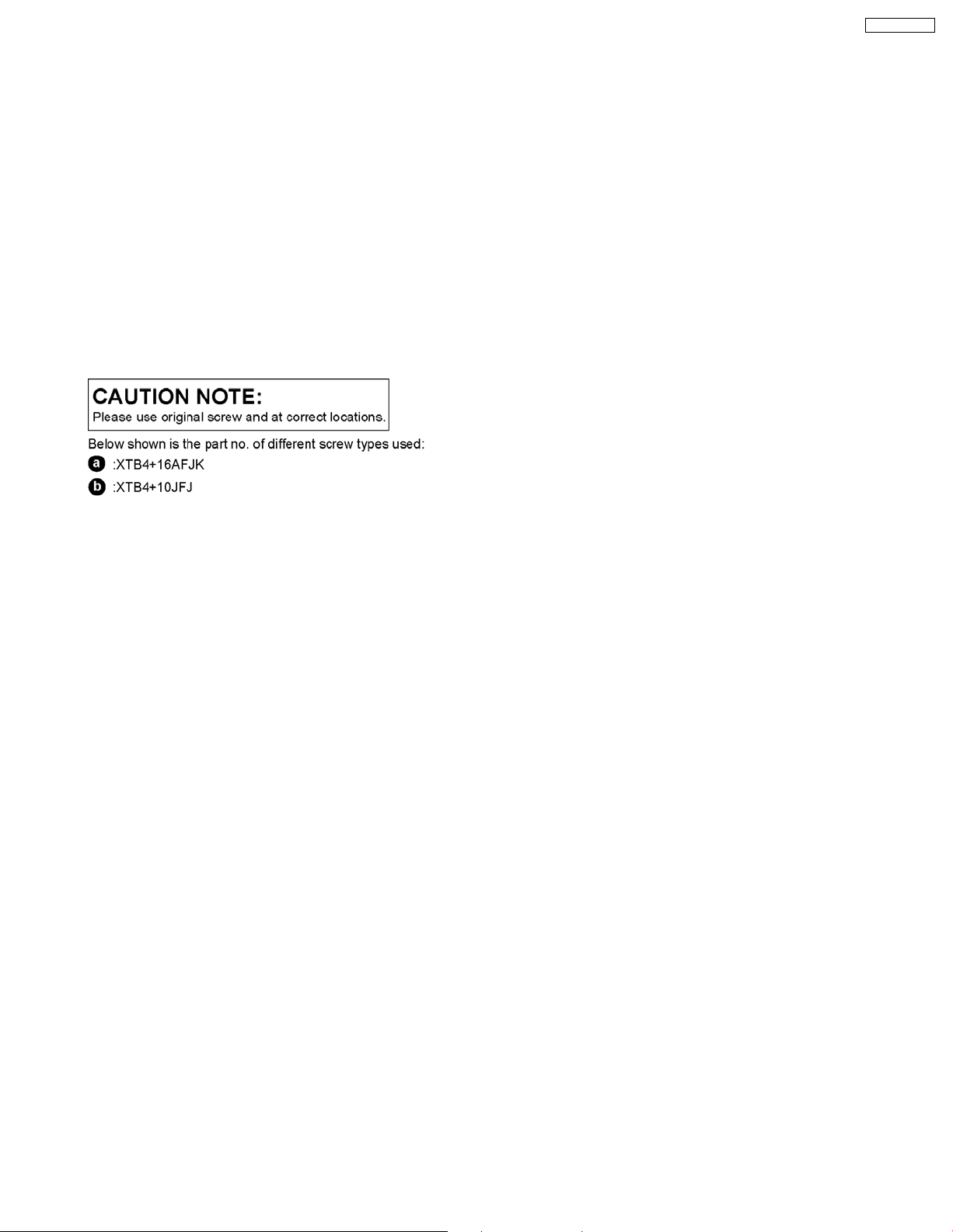
2.1. Disassembly of Front panel
Step 3: Take out the front panel as arrow shown.
Step 1: Remove 4 screws.
Step 4: Detach the yellow (+) and black (-) wires.
Step 2: Insert flathead screwdriver into the grooves to push the
front panel as arrow shown.
4
Page 5

Step 5: Detach the gray (+) and blue (-) wires.
Step 6: Remove front panel as arrow shown.
SB-PS960GCP
2.2. Disassembly of Tweeter (SP1)
Step 1: Remove front panel (Follow step 1 to step 4 in section
2.1).
Step 2: Remove 4 screws.
Step 3: Remove tweeter (SP1) as arrow shown.
5
Page 6

SB-PS960GCP
2.3. Disassembly of Woofer (SP2)
Step 1: Remove front panel (Follow step 1 to step 3 and step
5 in section 2.1).
Step 2: Remove 4 screws.
Step 3: Remove woofer (SP2) as arrow shown.
6
Page 7

3 Connection of the Speaker Cables
SB-PS960GCP
7
Page 8

SB-PS960GCP
8
Page 9

4 Exploded view
4.1. Cabinet Parts Location
SB-PS960GCP
9
Page 10

SB-PS960GCP
4.2. Packaging (SB-PS960GCPK)
10
Page 11

4.3. Packaging (SB-AK960GCPK)
Note: The diagram shows the packaging for speakers in SB-AK960GCPK.
SB-PS960GCP
11
Page 12

SB-PS960GCP
12
Page 13

5 Replacement Parts List
Notes :
• Important safety notice :
When replacing any of these components, be sure to use
only manufacturer’s specified parts shown in the parts list.
• [M] markings in the Remarks columns indicates parts
supplied by PAVCSG .
Ref.
No.
1 RYPX0245-K FRONT PANEL ASS’Y [M]
2 RYKX0371-K SPEAKER CAB. ASS’Y [M]
3 RKA0072-K LEG CUSHION [M]
4 RGNX0565-K SPEC SHEET [M]
5 XTB4+10JFJ SCREW [M]
6 XTB4+16AFJK SCREW [M]
C1 JFN22501015H CAPACITOR [M]
P1 RPGX1814 PACKING CASE [M]
P2 RPNX0501 POLYFOAM [M]
P3 RPFX0227 MIRAMAT BAG [M]
Part No. Part Name & Description Remarks
CABINET AND CHASSIS
CAPACITORS
PACKING MATERIALS
SB-PS960GCP
SPEAKERS
SP1 L0AA06A00060 TWEETER [M]
SP2 L0AA12A00021 WOOFER [M]
13
FLE0707
 Loading...