

Panasonic SBPS-960-GC Service manual
T
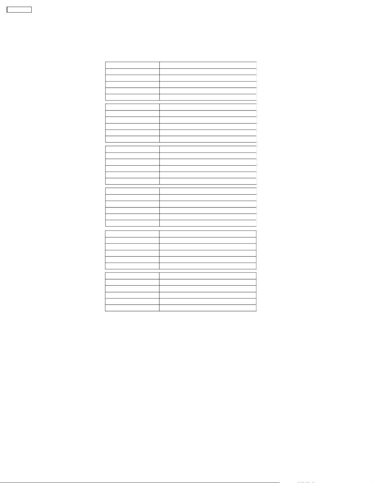
Specification
ORDER NO. MD0707012CE
Speaker System
SB-PS960GC
SB-PT960GC
Colour
(K)... Black Type
ype 2 way, 3 speaker system (Bass reflex)
Speaker unit(s) Impedance 3 Ω
1. Full range 8cmConetype
2. Full range 8cmConetype
3. Super tweeter Piezo type
Input power (IEC) 110 W* (Max)
Output sound pressure 82 dB/W (1.0 m)
Cross over frequency 10 kHz
Frequencyrange 100 Hz to 24 kHz (-16 dB)
110 Hz to 22 kHz (-10 dB)
Dimensions (W x H x D) 140 mm x 331 mm x 146.5 mm
Mass 1.6 kg
Notes :
1. Specifications are subject to change without notice.
Mass and dimensions are approximate.
2. Total harmonic distortion is measured by the digital spectrum
analyzer.
* Rating with low-cut filter equipped amplifier.
© 2007 Matsushita Electric Industrial Co. Ltd.. All
rights reserved. Unauthorized copying and
distribution is a violation of law.
SB-PS960GC
1 System Combination
1.1. System Breakdown
Note :
The tables below show the breakdown for speaker combinations used in main unit systems.
System SC-VK960GC-K
Music center SA-VK960GC-K
Front speakers
Surround speakers
Center speaker
Subwoofer
System SC-VK960EE-K
Music center SA-VK960EE-K
Front speakers
Surround speakers
Center speaker
Subwoofer
System SC-VK960GCSK
Music center SA-VK960GCSK
Front speakers
Surround speakers
Center speaker
Subwoofer
System SC-VK960GCTK
Music center SA-VK960GCTK
Front speakers
Surround speakers
Center speaker
Subwoofer
SB-PF960GC-K
SB-PS960GC-K
SB-PC960GC-K
SB-WVK960GC-K
SB-PF960GC-K
SB-PS960GC-K
SB-PC960GC-K
SB-WVK960GC-K
SB-PF960GC-K
SB-PS960GC-K
SB-PC960GC-K
SB-WVK960GC-K
SB-PF960GC-K
SB-PS960GC-K
SB-PC960GC-K
SB-WVK960GC-K
System SC-VK960GS-K
Music center SA-VK960GS-K
Front speakers
Surround speakers
Center speaker
Subwoofer
System SC-VK960GCPK
Music center SA-VK960GCPK
Front speakers
Surround speakers
Center speaker
Subwoofer
SB-PF960GC-K
SB-PS960GC-K
SB-PC960GC-K
SB-WVK960GC-K
SB-PF960GC-K
SB-PS960GC-K
SB-PC960GC-K
SB-WVK960GC-K
2
2 Assembling and Disassembling
“ATTENTION SERVICER”
Some chassis components may have sharp edges. Be careful when disassembling and servicing.
1. This section describes procedures for checking the operation and replacing the main components.
2. For reassembly after operation checks or replacement, reverse the respective procedures.
Special reassembly procedures are described only when required.
3. Select items from the following index when checks or replacement are required.
4. Refer to the Parts No. on the page of “Parts Locatio n and Replacement Parts List” (Section 5), if necessary.
Below is the list of disassembly sections
• Disassembly of Rear cabinet assembly
• Disassembly of Woofer 1 (SP1)
• Disassembly of Piezzo wire assembly
• Disassembly of Woofer 2 (SP1)
SB-PS960GC
3
SB-PS960GC
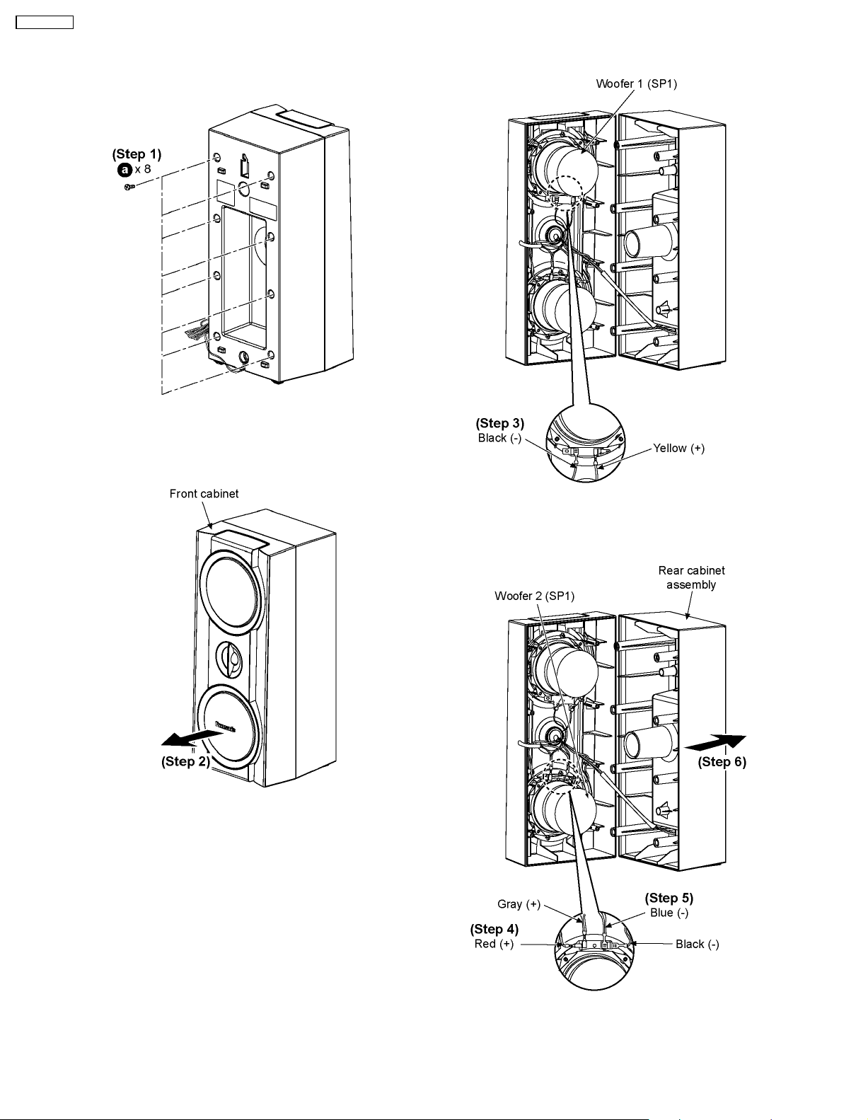
2.1. Disassembly of Rear cabinet assembly
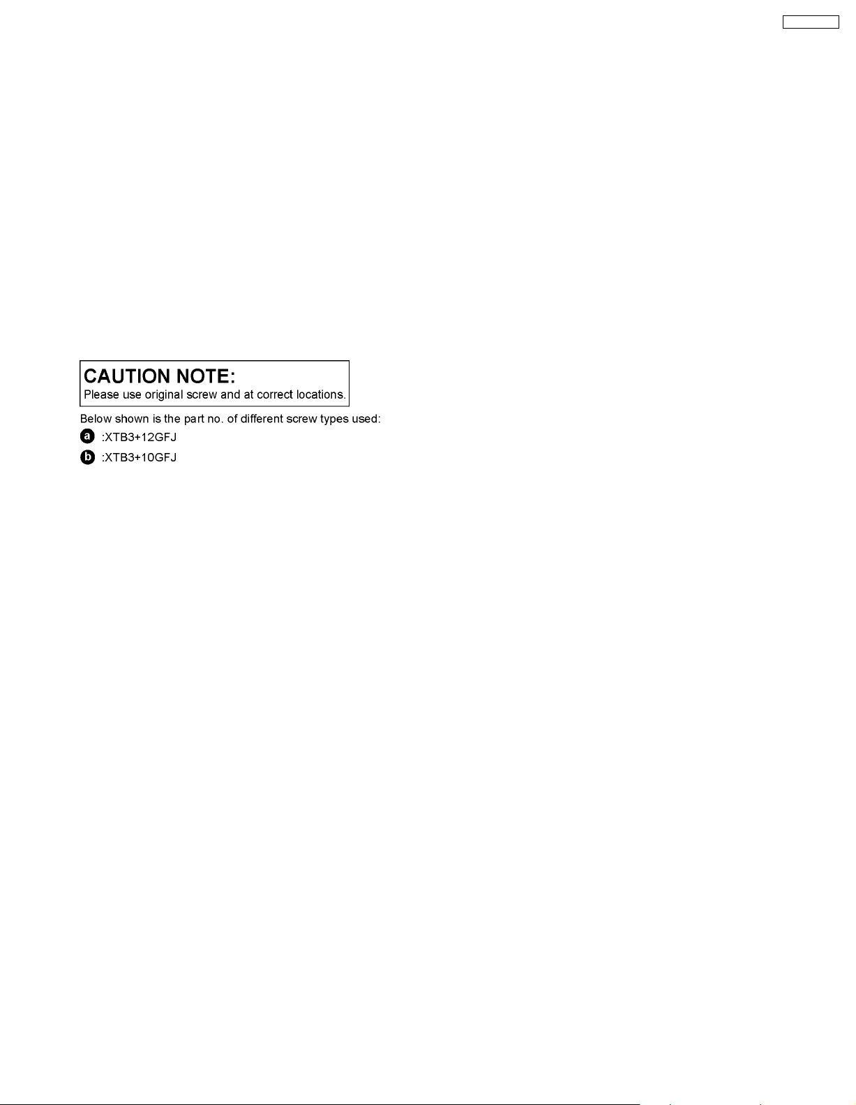
Step 1: Remove 8 screws.
Step 3: Detach the yellow (+) and black (-) wires.
Step 2: Detach the front cabinet as arrow shown.
Step 4: Detach the red (+) and black (-) wires.
Step 5: Detach the gray (+) and blue (-) wires.
Step 6: Remove the rear cabinet assembly as arrow shown.
4
 Loading...