

Specification
Type 3 way, 3 speaker system
Speaker (s)
Woofer 10 cm cone type (6 Ω)
Tweeter 6 cm cone type (6 Ω )
Super tweeter 2.5 cm piezo type
Impedance 6 Ω
Input power (IEC)
High 90 W (Max)
Low 90 W (Max)
Output sound pressure 80 dB/W (1.0 m)
Crossover frequency 2.2 kHz
Frequency range 45 Hz to 35 kHz (-16 dB)
ORDER NO. MD0702005CE
Speaker System
SB-PM54GN
Colour
(M)... Wood Type
50 Hz to 31 kHz (-10 dB)
Dimensions (W x H x D) 144 x 249 x 200 mm
Mass 2.0 kg
Notes :
1. Specifications are subject to change without notice.
Mass and dimensions are approximate.
2. Total harmonic distortion is measured by the digital spectrum
analyzer.
3. The labels “HIGH” and “LOW” on the rear or the speakers refer to
High frequency and Low speakers refer to High frequency and Low
frequency.
CONTENTS
Page Page
1 System Combination 3
1.1. System Breakdown
2 Assembling and Disassembling
2.1. Disassembly flow chart
2.2. Disassembly of Net frame assembly
2.3. Disassembly of Front Panel
2.4. Disassembly of Piezzo ornament
2.5. Disassembly of Tweeter
3
4
4
5
5
6
7
2.6. Disassembly of Woofer
2.7. Assembly of Speaker Unit
3 Connection of the Speaker Cables
4 Connection of the Wiring Diagram
5 Exploded view
5.1. Cabinet Parts Location
5.2. Packaging
© 2007 Matsushita Electric Industrial Co. Ltd.. All
rights reserved. Unauthorized copying and
distribution is a violation of law.
10
11
12
12
13
8
9

SB-PM54GN
6 Replacement Parts List 14
2

1 System Combination
1.1. System Breakdown
Note :
The table below show the breakdown for speaker combinations used in main unit systems.
System SC-PM54GN-K
Music center SA-PM54GN-K
Speaker system SB-PM54GN-M
SB-PM54GN
3
SB-PM54GN
2 Assembling and Disassembling
“ATTENTION SERVICER”
Some chassis components may have sharp edges. Be careful when disassembling and servicing.
1. This section describes procedures for checking the operation of the major printed circuit boards and replacing the main
components.
2. For reassembly after operation checks or replacement, reverse the respective procedures.
Special reassembly procedures are described only when required.
3. Select items from the following index when checks or replacement are required.
4. Refer to the Parts No. on the page of “Parts Location and Replacement Parts List” (Section 6), if necessary.
Below is the list of disassembly sections
· Disasse mbly of Net frame assembly
· Disasse mbly of Front panel
· Disasse mbly of Piezzo ornament
· Disasse mbly of Tweeter
· Disasse mbly of Woofer
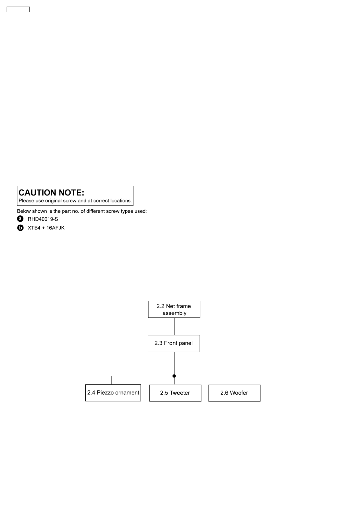
2.1. Disassembly flow chart
The following chart is the procedure for disassembling the casing and inside parts for internal inspection when carrying out the
servicing.
To assemble the unit, reverse the steps shown in the chart as below.
4
SB-PM54GN
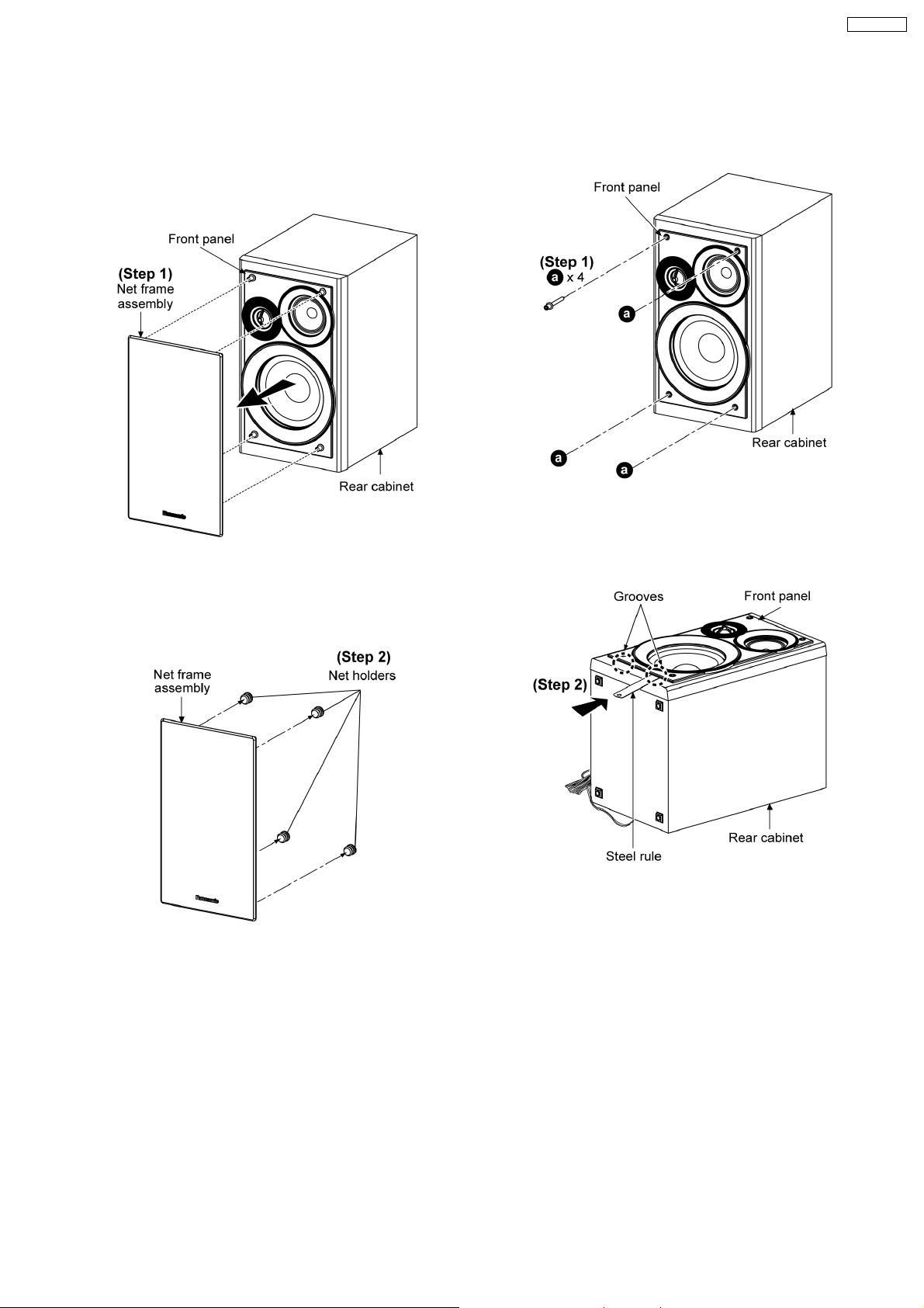
2.2. Disassembly of Net frame
assembly
Note: The disassembly process illustrates left speaker only. For
right speake r, the disassembly process is the same.
2.3. Disassembly of Front Panel
Follow (step 1) in item 2.2.
Step 1: Remove 4 screws.
Step 1: Remove net frame assembly as arrow shown.
Step 2: Remove 4 net holders.
Step 2: Insert a small steel rule into the grooves of the front
panel and lift up to make a gap allowance between the front
panel and rear cabinet as arrow shown.
5
 Loading...