

Page 1
Specification
Type 1 way, 1 speaker system
Speaker(s)
Full range 10 cm (4”) cone type 6 Ω
Impedance 6 Ω
Input power (IEC) 5W(Max)
Output sound pressure 83 dB/W (1.0 m)
Frequency range 61 Hz to 17 kHz (-16 dB)
95 Hz to 15 kHz (-10 dB)
Dimensions (W x H x D) 139 x 227 x 136 mm
(5-15/32” x 8-15/16” x 5-11/32”)
Mass 1.3 kg (2.9lb.)
ORDER NO. MD0606209CE
Speaker System
SB-PM3P
Colour
(M)... Wood Type
Notes :
1. Specifications are subject to change without notice.
Mass and dimensions are approximate.
2. Total harmonic distortion is measured by the digital spectrum
analyzer.
nSystem : SC-PM321P-S
Music Center : SA-PM321P-S
Front Speaker : SB-PM3P-M
A6
CONTENTS
Page Page
1 Assembling and Disassembling 2
1.1. Disassembly flow chart
1.2. Disassembly of Net frame assembly
1.3. Disassembly of Woofer
1.4. Assembly of Speaker unit
2 Connection of the Speaker Cables
3 Connection of the Wiring Diagram 7
2
4 Exploded view
3
4
5
6
4.1. Cabinet Parts Location
4.2. Packaging
5 Replacement Parts List
© 2006 Matsushita Electric Industrial Co. Ltd.. All
rights reserved. Unauthorized copying and
distribution is a violation of law.
7
7
8
8
Page 2
SB-PM3P
1 Assembling and Disassembling
“ATTENTION SERVICER”
Some chassis components may have sharp edges. Be careful when disassembling and servicing.
1. This section describes procedures for checking the operation of the major printed circuit boards and replacing the main
components.
2. For reassembly after operation checks or replacement, reverse the respective procedures.
Special reassembly procedures are described only when required.
3. Select items from the following index when checks or replacement are required.
4. Refer to the Parts No. on the page of “Parts Location and Replacement Parts List” (Section 5), if necessary.
Below is the list of disassembly sections
· Disasse mbly of Net Frame Assembly
· Disasse mbly of Woofer
· Disasse mbly of Speaker Cabinet Assembly
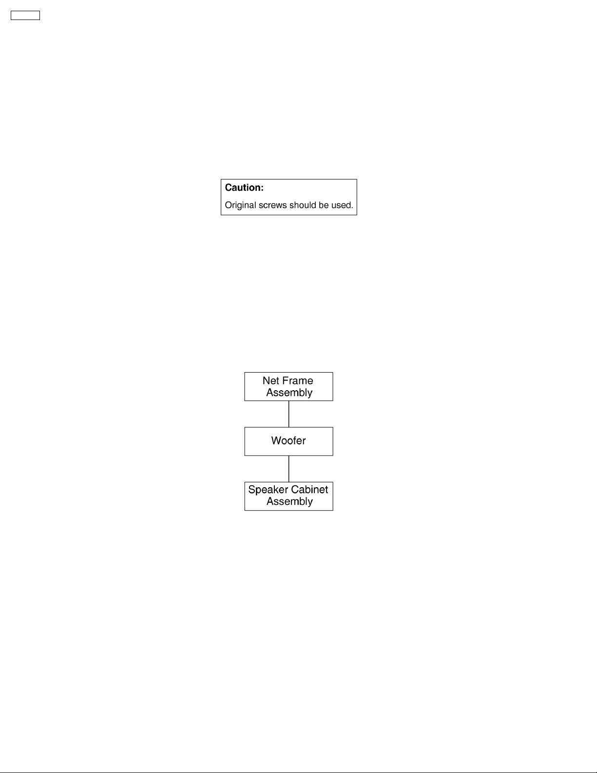
1.1. Disassembly flow chart
The following chart is the procedure for disassembling the casing and inside parts for internal inspection when carrying out the
servicing.
To assemble the unit, reverse the steps shown in the chart as below.
2
Page 3

1.2. Disassembly of Net frame
assembly
SB-PM3P
Step 1: Upset the speaker unit as shown above.
Step 2: Insert a steel rule into the grooves of speaker cabinet
assembly. Push the steel rule foward and backward as arrow
shown.
Caution:
Do not exert strong force as it may damage the net frame
assembly.
Step 5: Apply light force around the sides of speaker cabinet
assembly to push up the net frame assembly.
Caution:
Do not exert strong force as it may damage the net frame
assembly.
Step 3: Upset the speaker unit as shown above.
Step 4: Insert a flathead screwdriver above the steel rule as
shown.
3
Page 4

SB-PM3P
1.3. Disassembly of Woofer
Follow (step 1) to (step 5) in item 1.2.
Step 3: Remove the woofer by detaching the (+) red and (-)
black wires.
Step 1: Remove 4 screws from woofer.
Step 2: Insert a steel rule between the woofer and speaker
cabinet assembly to push out the woofer.
· Disasse mbly of Speak er cabinet assembly
4
Page 5

1.4. Assembly of Speaker unit
Step 1: Scrape off using the scriber and clean up the remaining
glue at the 6 bosses and 6 holes and replace with new glue.
SB-PM3P
Step 2: Replace the net frame assembly firmly back to the
speaker cabinet assembly.
5
Page 6

SB-PM3P
2 Connection of the Speaker Cables
· Be sure to connect speaker cables before connecting the
AC power supply cord.
· The load impedance of any speaker used with this unit must
be 6 Ω.
· Be sure to connect the cable from the right speaker to the
right terminal and the cable from the left speake r to the left
terminal.
1. Twist and pull off the vinyl tip of the speaker cords. If the
speaker cords do not have vinyl tips, connect them directly
to the terminals. Make sure the bare ends of the wires are
not unravelled.
2. Insert the wire to the rear panel of the unit and close the
lever.
Notes :
· To prevent damage to circuitry, never short-circuit positive
(+) and negative (-) speaker wires.
· Be sure to connect only positive (red) wires to positive (+)
terminals and negative (black) wires to negative (-)
terminals.
Placement
Speakers are designed identically so that no left or right
channel orientation is necessary.
Use only the supplied speakers
The combination of the main unit and speakers provide the
best sound. Using other speakers can damage the unit and
sound quality will be negatively affecte d.
Note
· Keep your speakers at least 10 mm away from the system
for proper ventilation.
· These speakers do not have magnetic shielding. Do not
place them near televisions, personal computers or other
devices easily influenced by magnetism.
· You cannot take the front net off the speakers.
Connection
6
Page 7

3 Connection of the Wiring Diagram
4 Exploded view
4.1. Cabinet Parts Location
SB-PM3P
7
Page 8

SB-PM3P
4.2. Packaging
5 Replacement Parts List
Notes :
· Important safety notice :
When replacing any of these components, be sure to use
only manufacturer’s specified parts shown in the parts list.
· [M] markings in the Remarks columns indicates parts
supplied by PAVCSG.
Ref.
No.
1 RFKGBPM3EG-M NET FRAME ASS’Y [M]
2 RFKHBPM3EG-M SPEAKER CAB. ASS’Y [M]
3 RMQ0819 EVA PACKING [M]
4 XTB4+16AFJ SCREW [M]
5 RGNV0208-K SPEC LABEL [M]
6 RKA0072-KJ LEG CUSHION [M]
P1 RPNV0094-J POLYFOAM [M]
P2 RPFV0056 MIRAMAT [M]
SP1 L0AA09A00007 WOOFER [M]
Part No. Part Name & Description Remarks
CABINET AND CHASSIS
PACKING MATERIALS
SPEAKER
8
FLE0606W/S
 Loading...